

Page 1
®
We’d like to take a moment to thank you for purchasing the Roland Percussion
Sound Module TD-10.
Before using this unit, carefully read the sections entitled: “IMPORTANT SAFETY
INSTRUCTIONS” (p. 2), “USING THE UNIT SAFELY” (p. 3, 4), and “IMPORTANT
NOTES” (p. 17). These sections provide important information concerning the
proper operation of the unit. Additionally, in order to feel assured that you have
gained a good grasp of every feature provided by your new unit, this manual should
be read in its entirety. The manual should be saved and kept on hand as a
convenient reference.
Copyright © 1997 ROLAND CORPORATION
All rights reserved. No part of this publication may be reproduced in
any form without the written permission of ROLAND CORPORATION.
Page 2
CAUTION
RISK OF ELECTRIC SHOCK
DO NOT OPEN
ATTENTION: RISQUE DE CHOC ELECTRIQUE NE PAS OUVRIR
CAUTION: TO REDUCE THE RISK OF ELECTRIC SHOCK,
DO NOT REMOVE COVER (OR BACK).
NO USER-SERVICEABLE PARTS INSIDE.
REFER SERVICING TO QUALIFIED SERVICE PERSONNEL.
The lightning flash with arrowhead symbol, within an
equilateral triangle, is intended to alert the user to the
presence of uninsulated “dangerous voltage” within the
product’s enclosure that may be of sufficient magnitude to
constitute a risk of electric shock to persons.
The exclamation point within an equilateral triangle is
intended to alert the user to the presence of important
operating and maintenance (servicing) instructions in the
literature accompanying the product.
INSTRUCTIONS PERTAINING TO A RISK OF FIRE, ELECTRIC SHOCK, OR INJURY TO PERSONS.
IMPORTANT SAFETY INSTRUCTIONS
SAVE THESE INSTRUCTIONS
WARNING - When using electric products, basic precautions should always be followed, including the following:
Read all the instructions before using the product.
Do not use this product near water — for example, near a
bathtub, washbowl, kitchen sink, in a wet basement, or near
a swimming pool, or the like.
This product should be used only with a cart or stand that is
recommended by the manufacturer.
This product, either alone or in combination with an amplifier
and headphones or speakers, may be capable of producing
sound levels that could cause permanent hearing loss. Do
not operate for a long period of time at a high volume level
or at a level that is uncomfortable. If you experience any
hearing loss or ringing in the ears, you should consult an
audiologist.
The product should be located so that its location or position
does not interfere with its proper ventilation.
The product should be located away from heat sources such
as radiators, heat registers, or other products that produce
heat.
The product should be connected to a power supply only of
the type described in the operating instructions or as marked
on the product.
1.
2.
3.
4.
5.
6.
7.
8.
9.
10.
11.
A.
B.
C.
D.
E.
The power-supply cord of the product should be unplugged
from the outlet when left unused for a long period of time.
Care should be taken so that objects do not fall and liquids
are not spilled into the enclosure through openings.
The product should be serviced by qualified service
personnel when:
The power-supply cord or the plug has been damaged; or
Objects have fallen, or liquid has been spilled into the
product; or
The product has been exposed to rain; or
The product does not appear to operate normally or
exhibits a marked change in performance; or
The product has been dropped, or the enclosure
damaged.
Do not attempt to service the product beyond that described
in the user-maintenance instructions. All other servicing
should be referred to qualified service personnel.
GROUNDING INSTRUCTIONS
This product must be grounded. If it should malfunction or breakdown, grounding provides a path of least resistance for
electric current to reduce the risk of electric shock.
This product is equipped with a cord having an equipment-grounding conductor and a grounding plug. The plug must be
plugged into an appropriate outlet that is properly installed and grounded in accordance with all local codes and ordinances.
DANGER: Improper connection of the equipment-grounding conductor can result in a risk of electric shock. Check with a
qualified electrician or serviceman if you are in doubt as to whether the product is properly grounded.
Do not modify the plug provided with the product — if it will not fit the outlet, have a proper outlet installed by a qualified
electrician.
For the USA
The product which is equipped with a THREE WIRE GROUNDING TYPE LINE PLUG must be grounded.
WARNING:
IMPORTANT:
As the colours of the wires in the mains lead of this apparatus may not correspond with the coloured markings identifying
the terminals in your plug, proceed as follows:
The wire which is coloured GREEN-AND-YELLOW must be connected to the terminal in the plug which is marked by the
letter E or by the safety earth symbol or coloured GREEN or GREEN-AND-YELLOW.
The wire which is coloured BLUE must be connected to the terminal which is marked with the letter N or coloured BLACK.
The wire which is coloured BROWN must be connected to the terminal which is marked with the letter L or coloured RED.
THIS APPARATUS MUST BE EARTHED
THE WIRES IN THIS MAINS LEAD ARE COLOURED IN ACCORDANCE WITH THE FOLLOWING CODE.
GREEN-AND-YELLOW: EARTH, BLUE: NEUTRAL, BROWN: LIVE
For the U.K.
2
Page 3

•Before using this unit, make sure to read the instructions below, and the Owner’s Manual.
...........................................................................................................
•Do not open or perform any internal modifications
on the unit. (The only exception would be where
this manual provides specific instructions which
should be followed in order to put in place userinstallable options; see p. 43.)
...........................................................................................................
•When using the unit with a rack or stand recommended by Roland, the rack or stand must be carefully placed so it is level and sure to remain stable. If
not using a rack or stand, you still need to make
sure that any location you choose for placing the
unit provides a level surface that will properly support the unit, and keep it from wobbling.
...........................................................................................................
•Use only the attached power-supply cord.
...........................................................................................................
• Avoid damaging the power cord. Do not bend it
excessively, step on it, place heavy objects on it, etc.
A damaged cord can easily become a shock or fire
hazard. Never use a power cord after it has been
damaged.
...........................................................................................................
•In households with small children, an adult should
provide supervision until the child is capable of following all the rules essential for the safe operation
of the unit.
...........................................................................................................
• Protect the unit from strong impact.
(Do not drop it!)
...........................................................................................................
• Do not force the unit’s power-supply cord to share
an outlet with an unreasonable number of other
devices. Be especially careful when using extension
cords—the total power used by all devices you have
connected to the extension cord’s outlet must never
exceed the power rating (watts/amperes) for the
extension cord. Excessive loads can cause the insulation on the cord to heat up and eventually melt
through.
...........................................................................................................
• Before using the unit in a foreign country, consult
with your dealer, or qualified Roland service personnel.
...........................................................................................................
•Always turn the unit off and unplug the power cord
before attempting installation of the circuit board
(WAVE & SYSTEM EXPANSION BOARD TDW series; p.
43).
...........................................................................................................
• Do not put anything that contains water (e.g., flower
vases) on this unit. Also, avoid the use of insecticides, perfumes, alcohol, nail polish, spray cans, etc.,
near the unit. Swiftly wipe away any liquid that
spills on the unit using a dry, soft cloth.
...........................................................................................................
USING THE UNIT SAFELY
3
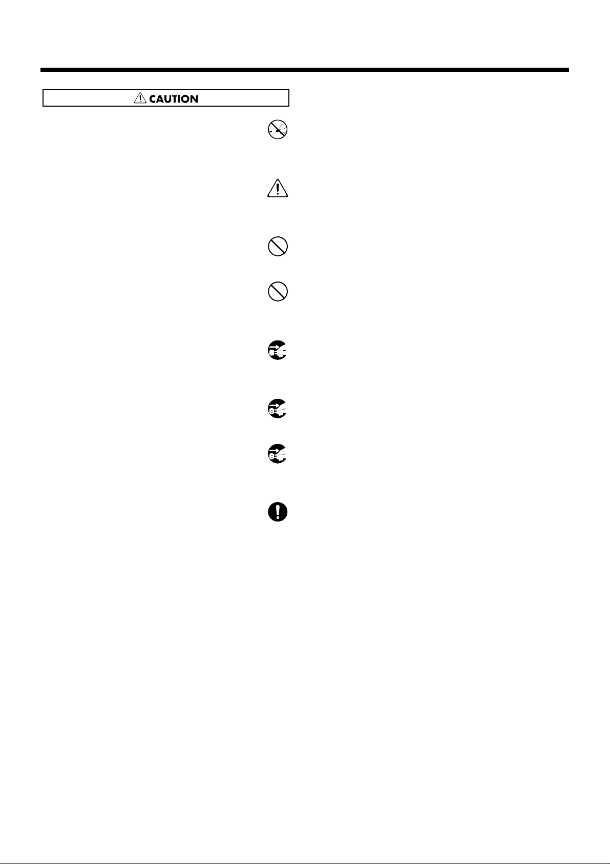
Used for instructions intended to alert
the user to the risk of injury or material
damage should the unit be used
improperly.
* Material damage refers to damage or
other adverse effects caused with
respect to the home and all its
furnishings, as well to domestic
animals or pets.
Used for instructions intended to alert
the user to the risk of death or severe
injury should the unit be used
improperly.
The ● symbol alerts the user to things that must be
carried out. The specific thing that must be done is
indicated by the design contained within the circle. In
the case of the symbol at left, it means that the powercord plug must be unplugged from the outlet.
The symbol alerts the user to important instructions
or warnings.The specific meaning of the symbol is
determined by the design contained within the
triangle. In the case of the symbol at left, it is used for
general cautions, warnings, or alerts to danger.
The symbol alerts the user to items that must never
be carried out (are forbidden). The specific thing that
must not be done is indicated by the design contained
within the circle. In the case of the symbol at left, it
means that the unit must never be disassembled.
Page 4
• Always grasp only the plug on the power-supply
cord when plugging into, or unplugging from, an
outlet or this unit.
...........................................................................................................
• Try to prevent cords and cables from becoming
entangled. Also, all cords and cables should be
placed so they are out of the reach of children.
...........................................................................................................
• Never climb on top of, nor place heavy objects on
the unit.
...........................................................................................................
• Never handle the power cord or its plugs with wet
hands when plugging into, or unplugging from, an
outlet or this unit.
...........................................................................................................
• Before moving the unit, disconnect the power plug
from the outlet, and pull out all cords from external
devices.
...........................................................................................................
• Before cleaning the unit, turn off the power and
unplug the power cord from the outlet (p. 27).
...........................................................................................................
• Whenever you suspect the possibility of lightning in
your area, pull the plug on the power cord out of
the outlet.
...........................................................................................................
• Install only the specified circuit board(s) (WAVE &
SYSTEM EXPANSION BOARD TDW series).
Remove only the specified screws (p. 43).
...........................................................................................................
USING THE UNIT SAFELY
4
Page 5

This owner’s manual is organized as follows.
Quick Start
This section is intended for those using the TD-10 for the first time, and explains how to use various
functions in a simple way. Please read Quick Start and follow along by actually operating the TD-
10. This will help you understand most of what you need to know for basic operations. If you find
unfamiliar words or terms, refer to the “Glossary” on p. 169. More advanced ways of using the TD10, or details of other operations are explained the Reference section.
Advanced Use
This section explains all functions of the TD-10 in detail and is divided into specific parts. Basic
panel operations and displays are covered in the Quick Start. The Advanced Use section assumes
you already understand basic procedures, so if anything’s unclear, refer to the “Quick Start.”
Chapter 1. Overview of the TD-10 V-drums
This chapter explains the concept of the TD-10 and how it is organized. Read this chapter in order to
understand what the TD-10 is.
Chapters 2–5. Functions for creating sound
If you wish to learn more about the sound creation possibilities introduced in the “Quick Start,”
refer to chapters 2–5.
Chapter 6. Using a sequencer and related functions
This chapter explains sequencer functions such as performance, recording, click settings, and pattern
editing.
Chapter 7. Settings for the entire TD-10
This chapter explains settings that affect the entire TD-10, such as adjusting the overall sound, saving data to a memory card etc.
Chapters 8 and 9. Convenient functions and how to use them
These chapters explain how to use pads or pedals for pattern play back, and other functions, and
about time-saving operations such as copy and help.
Chapter 10. Functions using MIDI
This chapter explains how to use MIDI—whether it be for saving data to an external device, or for
using the TD-10 as a sound module.
Appendices
If you run into problems, refer to “Troubleshooting” to make sure that the settings are correct. If an
error message appears during operation, refer to “Message/Error Message List” and take appropriate action. This section also provides information related to sound editing, MIDI, various lists, and
the MIDI implementation charts.
* The display screens printed in this owner’s manual are based on the factory settings. However, please be aware
that in some cases they may differ from the actual factory settings.
How to read this owner’s manual
5
Page 6

IMPORTANT SAFETY INSTRUCTIONS............................................................................2
USING THE UNIT SAFELY.................................................................................................3
How to read this owner’s manual........................................................................................5
Features............................................................................................................................12
Front and rear panel..........................................................................................................14
Important notes .................................................................................................................17
About button operations and the screen displays .............................................................18
Quick Start ..............................21
Before you begin playing..........................22
Mounting the TD-10 to the stand.......................................................................................22
Connect your audio system or amp...................................................................................23
Connecting pads and pedals.............................................................................................24
Turning on the power ........................................................................................................26
To turn the power off ........................................................................................................................27
Listening to the internal demo playback............................................................................28
Specify the pads that the TD-10 will use...........................................................................29
If you have purchased the “V-Basic Kit” or “V-Standard Kit”....................................................29
If you have purchased the PD-5, PD-7, PD-9, PD-100 or PD-120 individually .........................30
Using triggers on an acoustic drum to play the TD-10 .................................................................33
Check the settings.............................................................................................................34
For a better performance ..........................35
Concerning the performance & expressiveness of the pads.............................................35
Rim shots..............................................................................................................................................35
Choking................................................................................................................................................35
Positional sensing ...............................................................................................................................36
Playing with brushes..........................................................................................................................36
Hi-hat control pedal ...........................................................................................................................36
TD-10 operating procedure...............................................................................................37
Adjusting the volume.........................................................................................................................37
Selecting a drum kit............................................................................................................................38
Adjusting the sensitivity of a pad.....................................................................................................39
Master equalizer..................................................................................................................................40
Effect on/off ........................................................................................................................................41
Help function.......................................................................................................................................42
About expansion boards....................................................................................................43
À propos des cartes d’extension.......................................................................................44
(French language for Canadian Safety Standard)
Troubleshooting connections and settings........................................................................45
Features of the preset drum kits................47
How sounds are created on the V-drums..........................................................................47
No.36: 70’s Rock drum kit.................................................................................................48
No.37: Brush Kit................................................................................................................50
No.38: Electronic drum kit.................................................................................................52
Contents
6
Page 7

Modifying a drum kit................................54
[INST]: Creating drum sounds ..........................................................................................55
Selecting an instrument......................................................................................................................55
Modify the material and depth of the body....................................................................................56
Change the material and tuning of the head..................................................................................58
Adjust the muffling (muting) and snare strainer tension.............................................................60
[STUDIO]: Adjusting the acoustics of the room.................................................................62
Decide “where” the drums are played............................................................................................63
Change the size of the room..............................................................................................................64
[CONTROL ROOM]: Adding finishing touches to the sound.............................................65
Using the equalizer to modify the sound........................................................................................65
Adjusting the volume balance of the instruments.........................................................................67
Examples and convenient tips...................68
Perform with the on-board sequencer...............................................................................68
Playing back a preset pattern............................................................................................................68
Play the pads along with a preset pattern.......................................................................................69
Drum Kit Chain—Selecting drum kits in the desired order................................................70
Using a foot switch to select kits .......................................................................................72
Using a pad to playback patterns......................................................................................72
Using headphones to hear the click sound .......................................................................73
Using the TD-10 as a MIDI sound module........................................................................74
Advanced Use .........................75
Chapter 1. Overview of the TD-10 V-drums.......76
How the V-drums system is organized..............................................................................76
How to select pads............................................................................................................77
Using pads to select the pad/sound for editing ............................................................................77
Using the TD-10 to select the pad/sound for editing....................................................................77
Chapter 2. Settings for the entire drum kit ....78
Selecting a kit....................................................................................................................78
Selecting kits from the list display .....................................................................................78
Naming a kit ......................................................................................................................78
Making settings for brush performance.............................................................................79
Effect switches for the entire kit.........................................................................................79
Contents
7
Page 8

Chapter 3. Instrument settings ..................80
Selecting an instrument.....................................................................................................80
Selecting instruments from the list display........................................................................80
Editing an acoustic drum kit (V-EDIT) ..............................................................................81
Selecting the shell material................................................................................................................81
Changing the shell depth...................................................................................................................82
Selecting the head material................................................................................................................82
Tuning the head..................................................................................................................................82
Muffling settings (muting) ................................................................................................................83
Adjusting the snare strainer tension................................................................................................83
Editing an electronic drum kit (V-EDIT).............................................................................84
Editing a TR-808/909 (V-EDIT).........................................................................................85
Editing hi-hat, cymbals and percussion.............................................................................86
Chapter 4. Studio settings .........................87
Settings for the entire drum kit ..........................................................................................87
Selecting the studio/room.................................................................................................................87
Changing the size of the room..........................................................................................................87
Changing the wall material...............................................................................................................87
Selecting the ambience mike location..............................................................................................87
Adjusting the volume and output assignments of the ambience................................................88
Settings for each instrument..............................................................................................88
Adjusting the amount of ambience..................................................................................................88
Selecting the type of mike and its location......................................................................................88
Settings for each group.....................................................................................................89
Adjusting the amount of ambience send level for each group ....................................................89
Chapter 5. Control room settings...............90
Settings for each instrument..............................................................................................90
Adjusting volume (level)...................................................................................................................90
Adjusting pan (stereo location).........................................................................................................90
Adjusting effect send level ................................................................................................................90
Selecting output assignments............................................................................................................91
Controlling variations in volume (Compressor)............................................................................91
Customizing the tone (Equalizer).....................................................................................................92
Settings for the entire drum kit ..........................................................................................93
Adjusting effect Return level ............................................................................................................93
Selecting the type of effect.................................................................................................................93
Editing the effects ...............................................................................................................................94
Settings for an entire group...............................................................................................96
Adjusting effect send level for an entire group..............................................................................96
Adjusting the volume by group .......................................................................................................96
Contents
8
Page 9

Chapter 6. Sequencer................................97
Basic sequencer operation................................................................................................97
Using Preset Patterns .........................................................................................................................97
Setting the tempo..............................................................................................................97
Setting the tempo for each pattern...................................................................................................97
Temporarily changing the tempo of the currently-playing pattern............................................97
Playback functions ............................................................................................................98
Selecting a pattern...............................................................................................................................98
Selecting patterns from the list .........................................................................................................98
Selecting how a pattern will playback.............................................................................................98
Click settings.....................................................................................................................99
Click on/off and volume settings ....................................................................................................99
Setting the tempo................................................................................................................................99
Setting the time signature and click interval ..................................................................................99
Selecting the click sound..................................................................................................................100
Using ambience.................................................................................................................................100
Using effects ......................................................................................................................................100
Adjusting the pan (stereo location)................................................................................................100
Selecting the output destination.....................................................................................................100
Recording........................................................................................................................101
Basic recording procedure...............................................................................................................101
The Rehearsal function ....................................................................................................................102
Using a count-in................................................................................................................................102
Start recording the moment that you strike a pad.......................................................................102
Correcting timing as you record (Quantize).................................................................................103
Importing data from another sequencer into the TD-10.............................................................103
Editing a pattern..............................................................................................................103
Naming a pattern..............................................................................................................................103
Erasing a pattern...............................................................................................................................104
Erasing selected measures of a pattern..........................................................................................104
Copying a pattern.............................................................................................................................104
Copying selected measures of a pattern........................................................................................105
Clearing a pattern .............................................................................................................................105
Clearing selected measures of a pattern........................................................................................105
Connecting two patterns..................................................................................................................106
Settings for part instruments ...........................................................................................106
Adjusting the master tuning ...........................................................................................................106
Instrument selection and settings for each part ...........................................................................106
Mixer settings for each part.............................................................................................................107
Muting a specific part.......................................................................................................................107
Contents
9
Page 10

Chapter 7. Settings for the entire TD-10...108
Changing output assignment for audio received by the MIX IN jack...............................108
Specifying the type of pad...............................................................................................108
Basic settings for the trigger parameters (BASIC) ..........................................................109
Detailed settings for the trigger parameters (ADVNCD)..................................................111
The order in which trigger parameters should be set when using drum triggers.............112
Adjusting the brightness of the display............................................................................113
Setting the master equalizer............................................................................................113
Saving data to a memory card ........................................................................................114
Loading data from a memory card ..................................................................................115
Automatically switching the display (Note Chase)...........................................................115
Chapter 8. Convenient functions..............116
Selecting kits in the desired order (Drum Kit Chain) .......................................................116
Specifying a Drum Kit Chain..........................................................................................................116
Naming a Drum Kit Chain..............................................................................................................116
Copying...........................................................................................................................117
The UNDO function.........................................................................................................117
Getting help.....................................................................................................................118
Specifying how the Preview button functions..................................................................118
Chapter 9. Operations using pads and
foot switches ..........................................119
Using pads to play patterns (Pad Pattern) ......................................................................119
Using pads to perform button operations (Pad Switch) ..................................................119
Using foot switches to perform button operations (Foot Switch).....................................120
Chapter 10. Functions using MIDI ............121
Saving/Loading data to/from an external device (Bulk Dump)........................................121
Saving data ........................................................................................................................................121
Loading saved data to the TD-10....................................................................................................121
Setting the Device ID—Transmitting saved data to two or more TD-10 units........................122
Using pads to play an external MIDI sound module........................................................122
Selecting the note number transmitted by each pad ...................................................................122
Setting the Gate Time.......................................................................................................................123
Setting the MIDI channel.................................................................................................................123
Using the TD-10 with the Roland SPD-11.......................................................................123
MIDI settings for the entire TD-10...................................................................................124
Setting the MIDI channels for each Part........................................................................................124
Turning off Local Control................................................................................................................124
Disabling reception or transmission of Program Changes.........................................................124
Reducing the amount of data transmitted by the FD-7 (Pedal Data Thin) ..............................124
Using the TD-10 as a sound module...............................................................................125
Setting the instrument for each part ..............................................................................................125
Adjusting the mixer settings for each part....................................................................................125
Regarding note numbers for the drum kit sounds ......................................................................125
Using the percussion group ............................................................................................................126
Changing the kit number that is selected by a program change...............................................128
Contents
10
Page 11

MIDI messages for detailed performance expressions...................................................128
Messages for hi-hat control .............................................................................................................128
Messages for positional sensing (snare drum and ride cymbal only).......................................129
Synchronization with external MIDI devices....................................................................129
Appendices............................131
Troubleshooting...............................................................................................................132
Instruments that can be used with each trigger...............................................................136
Restoring the factory settings (INITIALIZE).....................................................................137
Message / error message list..........................................................................................138
About MIDI ......................................................................................................................140
Using drum triggers.........................................................................................................142
Preset list.........................................................................................................................143
MIDI implementation .......................................................................................................154
MIDI implementation chart ..............................................................................................165
Specifications..................................................................................................................168
Glossary..........................................................................................................................169
Index of screen displays..................................................................................................173
Index................................................................................................................................176
* PinStripe is a registered trademark of Remo Inc. U.S.A.
Contents
11
Page 12

●Enhanced tonal quality and expressiveness that rivals acoustic
drums
The TD-10 features a newly developed modeling sound module that relies on COSM technology.
The force and position of the hit are detected, providing sensitive and dynamic expression that is
extremely close to that of acoustic drums. In addition, when PD-100 or PD-120 (optional) pads are
used, you can enjoy excellent response when playing rolls.
* COSM (Composite Object Sound Modeling) is a Roland technology which combines multiple sound model-
ing processes to create new sounds.
* Positional detection is possible on snare drums and ride cymbals.
●With 600 drum sounds and 54 backing instrument provided
A rich array of instrumental sounds are provided, sufficient to cover all styles of music.
●A user interface comfortable for drummers
You can create sounds much in the same way that you would using acoustic drums when you select
a preferred drum head, tune it, and attach muffling (muting) material. With the large display, the
use of graphics and icons to portray parameters being set and their meanings, operation is intuitive
and easily understood.
●High-speed trigger response
The triggering time (time delay from hitting the pad until you hear the sound) is faster than ever,
allowing expressiveness and dynamics to be reproduced accurately.
●Twelve pads can be used simultaneously
Since up to twelve pads can be used simultaneously, you can create large-scale setups bigger than
ever before. This also gives you flexibility for extended applications, such as using pads as switches
(Pad Switch) or for pattern playback (Pad Pattern).
●Simulate the entire process of actual recording
By being able to choose drum materials, sizes, studio location, mike types and their settings, effects
and mixer parameters, the TD-10 allows total flexibility for recording or live applications. All of
these settings can be stored as part of a drum kit,for instant recall at any time.
●Perform using brushes
If you use the PD-100 or PD-120 pads, you can play with brushes, something not possible with any
previous electronic drum system. (Nylon brush only please!).
●Sound processing specially selected for drums
For each instrument assigned to trigger inputs 1–10, individual two-band equalizers and compressors are provided. In addition,(in the control room) —there are digital effects: reverbs, flanger, chorus, delays, pitch shift delay, and phaser. A three-band equalizer is also provided for processing the
sound at the MASTER OUT. Ambience(in the Studio) lets you choose WHERE the drums are being
played. You can change the sound of that space by changing the material of the walls, size of the
room and the position of the ambient mikes. There are individual ambience send levels for all
instruments.
Features
12
Page 13

●Functions and operations perfect for live performances
The group faders on the front panel let you make quick changes as needed during performance. You
can play drum kits in any desired order (Drum Kit Chain). The INC/DEC buttons are large enough
to be pressed with a drum stick. (Don’t HIT them!) Another very useful function allows you to send
the click sound ONLY to the headphones if desired. An audio input (stereo) for custom monitoring
(MIX IN jack) is also provided.
●Easy-operation sequencer is built-in
With easy, tape recorder-like operations, you can record or play back patterns. In addition to the
drums, three backing parts can be added for ensemble practice or for creating backing patterns via
MIDI keyboard, external sequencer etc.
* Brush swish/sweeping and choke cannot be recorded.
●Previous models of pads can be used
Previous pad models (PD-5, PD-7, PD-9), kick trigger units (KD-5, KD-7) and the hi-hat control
pedal (FD-7) are all compatible. Also, the PD-7 and PD-9 allow positional sensing for the snare drum
and ride cymbal.
●User Installable Expansion boards allow extended functionality
WAVE & SYSTEM EXPANSION BOARD TDW series will bring more instruments and drum kits to
the TD-10, and allows the system to be upgraded through Flash ROM. A memory card (M-512E) can
be used to store all kits and patterns for the TD-10.
●Usable as a MIDI sound module
Percussion groups are provided so these sounds can be accessed via MIDI as with a dedicated module, so in addition to sounds assigned to the 12 trigger inputs, a special note map for percussion
allows 72 types of instruments to be accessed simultaneously.
Features
13
Page 14
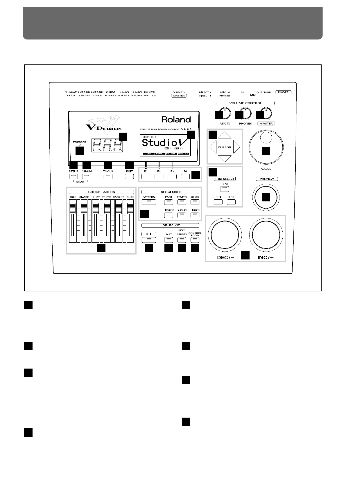
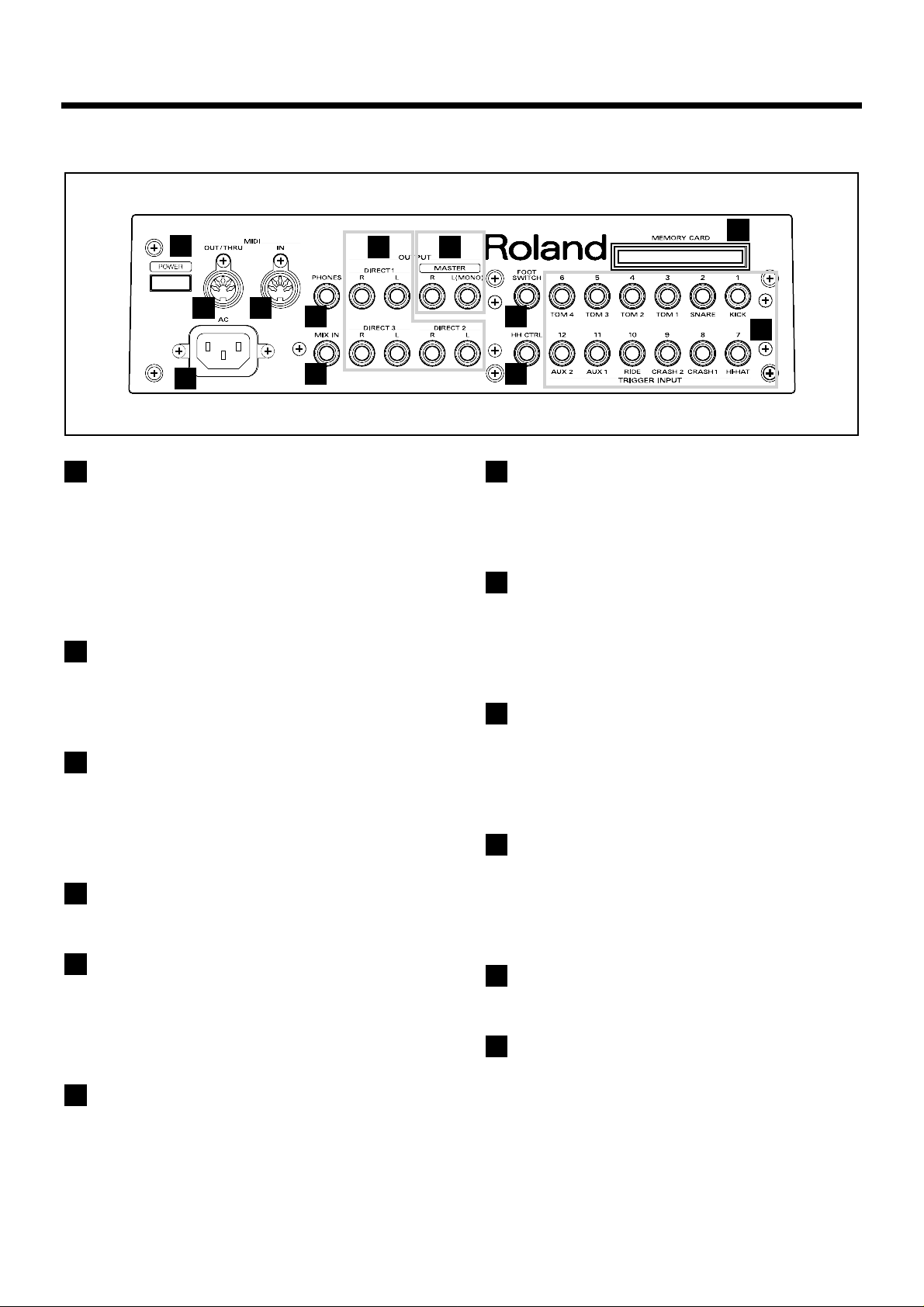
Front Panel
1
2
3
4
5678
9
10
11 12 13 14
15 16 17
18
20
19
21
22
Front and rear panel
14
Trigger Indicator
This will light when a trigger signal (signal produced when
pad is struck) is received from a pad. It allows you to check
whether the pad has been connected correctly.
LED Display
Displays the number of the currently selected drum kit.
Graphic Display
During performance, this indicates the drum kit name and
other important information. During editing, various graphics and text relative to the editing process is indicated.
* In this owner’s manual, this will be referred to simply as
“the display.”
F1-F4 Buttons
These buttons change their function depending on the contents of the display. The lower part of the display will indicate the function of each button (p. 18).
EXIT Button
Press this button and you will return to the screen one level
higher in the hierarchy. Repeated pressing takes you back to
the “DRUM KIT” page.
TOOLS Button
Provides access to functions such as Copy, Undo, and Help.
(p. 42, 117)
CHAIN Button
Lets you make Drum Kit Chain settings (a function that
arranges drum kits in a desired order for successive selection) (p. 70, 116).
SETUP Button
Here you can make settings that affect the entire TD-10, such
as trigger parameters and MIDI settings (p. 108).
1
2
3
4
5
6
7
8
Page 15

GROUP FADERS
These allow you to adjust the volume of the kick, snare, hihat, other percussion instruments, backing instruments, and
the click sound (p. 37).
SEQUENCER
Here are the buttons that control sequencer functions (playback/recording of performance patterns) (p. 68, 97).
KIT Button
Provides access to the basic display page used when playing
the TD-10.
INST (Instrument) Button
Provides access to the display page in which you can edit
instruments (p. 55, 80).
STUDIO Button
Provides access to the display page where you can choose
mike types, their positions, ambience types and ambient
mike positions (p. 62, 87).
CONTROL ROOM Button
Allows you to edit mixer, EQ, compressor and effect parameters (p. 65, 90).
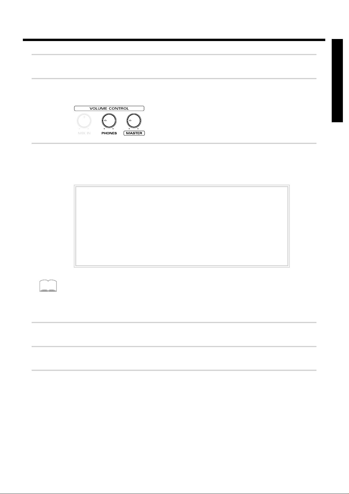
MIX IN Knob
This adjusts the volume of the device connected to the MIX
IN jack. The sound from the MIX IN will be output from the
MASTER out and/or the PHONES jack.
PHONES Knob
Adjusts the headphone volume. Even when headphones are
connected, sound will still be output from the various output jacks.
MASTER Knob
Adjusts the volume of the MASTER OUT jacks. The volume
of the PHONES jack is adjusted by the PHONES knob.
CURSOR Buttons
Used to move the cursor in the display, or to access the next
display page (p. 18).
VALUE Dial
This dial has the same function as the INC and DEC buttons.
Use this dial when you wish to make large changes in drum
kit settings or edited values (p. 19).
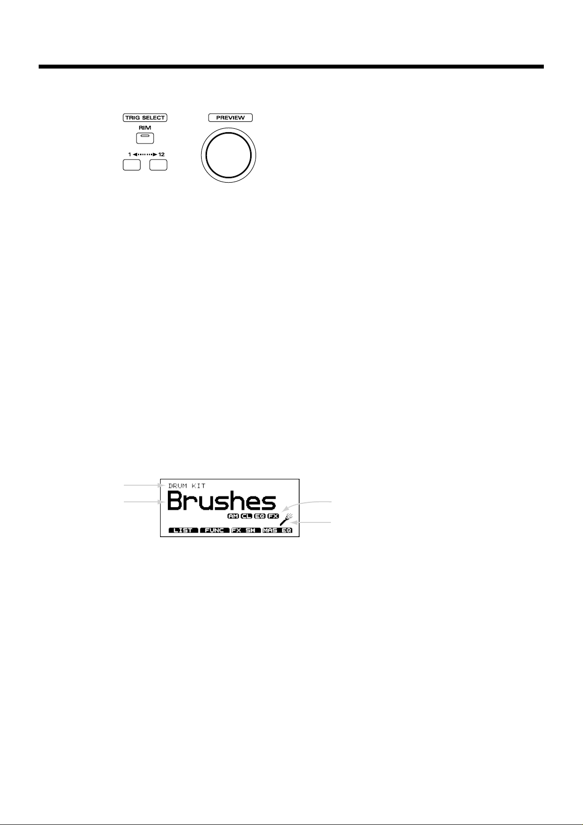
TRIG SELECT
Use the lower two buttons to select the pad (trigger number)
for which you wish to make settings. To select the rim of a
pad, press the RIM button, then the RIM indicator is lit. If
pads are connected to the TD-10, you can also select a pad
by striking it. The PREVIEW button lets you audition the
instrument that is assigned to the selected pad or the sound
appearing in the display when editing a percussion group
(p. 20).
PREVIEW Button
Used to audition an instrument. By using TRIG SELECT buttons to select a pad, you can play and edit sound even if no
pads are connected to the TD-10. The button is velocity sensitive (p. 20).
INC Button, DEC Button
These buttons are used to switch drum kits or to modify values. Pressing the INC button increases the value, and pressing the DEC button decreases it. Since these buttons are
large, you can also use the tip of your drum stick to press
them (p. 19).
* Please be aware that hitting the buttons with a stick can
cause malfunctions.
9
10
11
12
13
14
15
16
17
18
19
20
21
22
Front and rear panel
15
Page 16
Rear Panel
23
24
2529
30
3132
33
34
26
2728
Front and rear panel
16
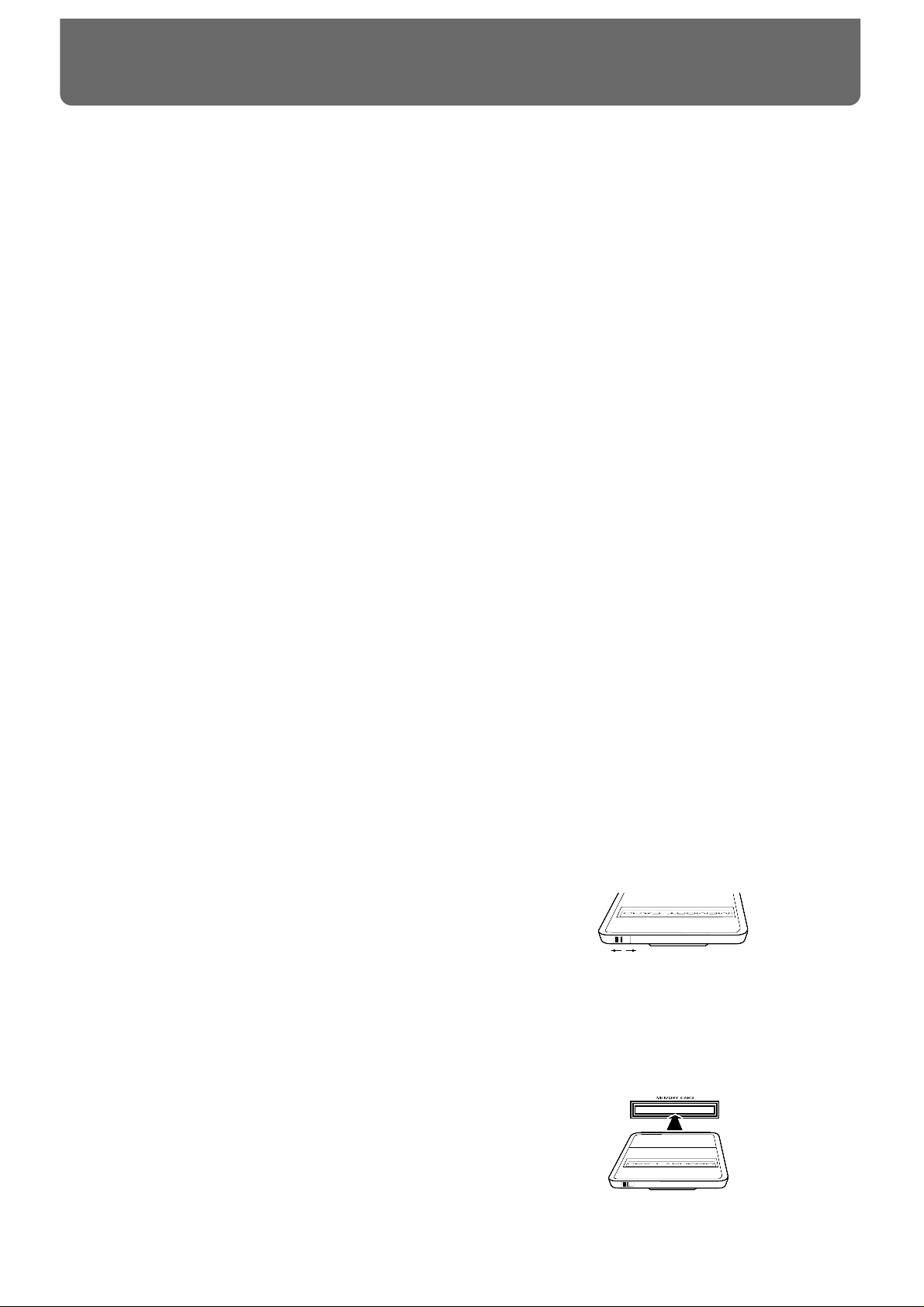
MEMORY CARD Slot
An M-512E memory card (optional) can be inserted into this
slot. Each memory card can store all settings of the TD-10,
such as drum kits and sequencer performance data, etc (p.
114).
* The M-512E is the only memory card that can be used by
the TD-10.
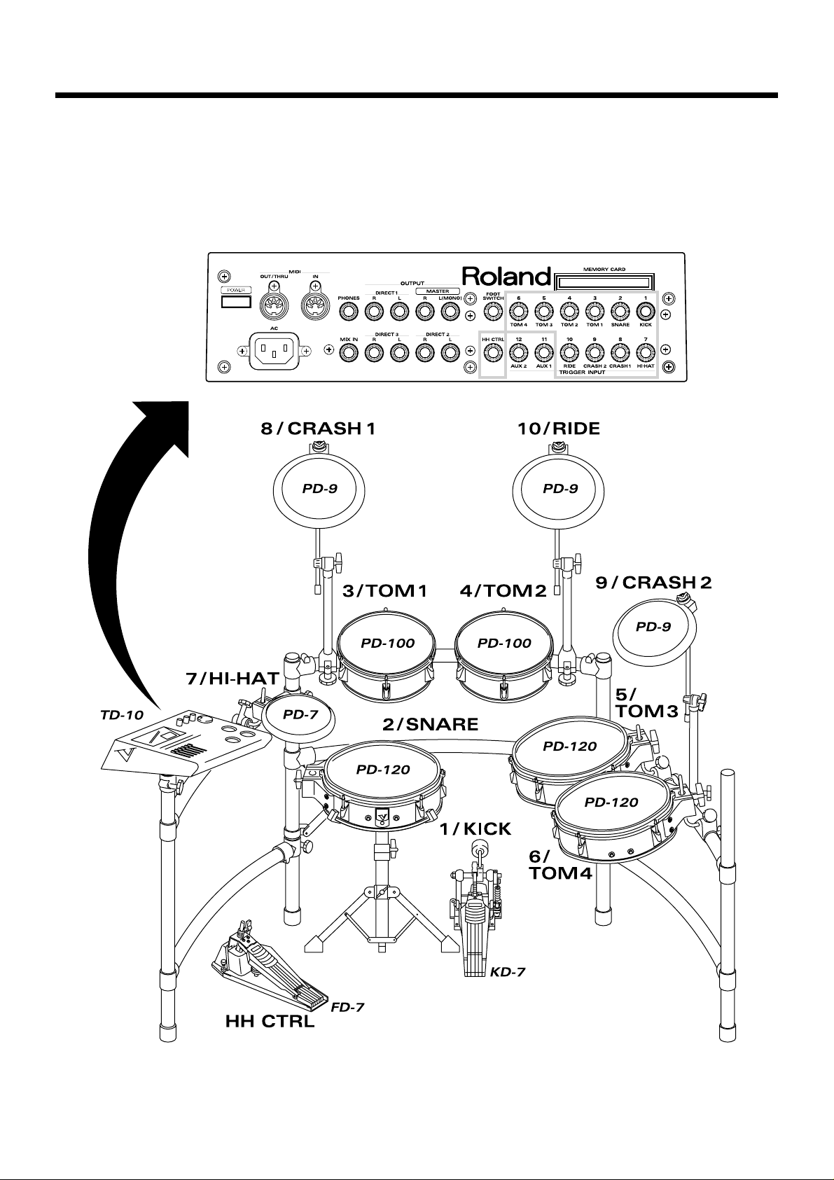
TRIGGER INPUT Jacks
Accept the pads or kick trigger units you want to connect to
the TD-10. To connect a dual trigger type pad (PD-7, PD-9,
PD-120), use a stereo cable (p. 24).
FOOT SWITCH Jack
Accepts connection of an optional foot switch (FS-5U). A
foot switch can be used to select kits and start/stop the
sequencer, etc. Use a special PCS-31 cable (optional) (p. 72,
120).
HH CTRL Jack
Accepts connection of a hi-hat control pedal (FD-7) (p. 36).
OUTPUT (MASTER) Jacks
These jacks output the instrumental sounds of the TD-10,
and are for connection to external audio devices or amps. If
you are listening in mono, connect to only the MASTER L
(MONO) jack (p. 23).
OUTPUT (DIRECT 1, 2, 3) Jacks
The direct outs allow you to have more “separation,” over
the total kit, and can be used for external effects etc.
Ambience may also be sent from these outputs, but NOT the
digital effects. Output assignments DIRECT 1, 2 or 3 jacks
are found in the Control Room (p. 91).
PHONES Jack
A pair of stereo headphones can be connected to this jack.
Even if headphones are connected, sound will still be output
from the OUTPUT jacks (p. 23).
MIX IN Jack
This jack is used to connect a CD or cassette player, or as a
custom monitoring input for live/recording performances.
The sound that is input to this jack will be output from the
MASTER out jacks and/or the PHONES jack (p. 108).
MIDI IN Connector
Use this connector when you wish to use an external MIDI
sequencer to play the sounds of the TD-10, or when loading
TD-10 settings (bulk data) that were saved on an external
device (p. 121).
MIDI OUT/THRU Connector
Use this connector when you wish to use play sounds in an
external MIDI sound module/sampler from the pads, or
when you wish to transmit TD-10 settings (bulk data) to
another MIDI device (p. 121).
POWER Switch
This switch turns the power on/off (p. 26).
AC Inlet
Connect the included AC power cable to this inlet (p. 23).
23
24
25
26
27
28
29
30
31
32
33
34
Page 17
Power Supply
● Do not use this unit on the same power circuit with any
device that will generate line noise (such as an electric
motor or variable lighting system).
● Before connecting this unit to other devices, turn off the
power to all units. This will help prevent malfunctions
and/or damage to speakers or other devices.
Placement
● Using the unit near power amplifiers (or other equipment
containing large power transformers) may induce hum. To
alleviate the problem, change the orientation of this unit;
or move it farther away from the source of interference.
● This device may interfere with radio and television recep-
tion. Do not use this device in the vicinity of such
receivers.
● Do not expose the unit to direct sunlight, place it near
devices that radiate heat, leave it inside an enclosed vehicle, or otherwise subject it to temperature extremes.
Excessive heat can deform or discolor the unit.
Maintenance
● For everyday cleaning wipe the unit with a soft, dry cloth
or one that has been slightly dampened with water. To
remove stubborn dirt, use a cloth impregnated with a
mild, non-abrasive detergent. Afterwards, be sure to wipe
the unit thoroughly with a soft, dry cloth.
● Never use benzene, thinners, alcohol or solvents of any
kind, to avoid the possibility of discoloration and/or
deformation.
Repairs and Data
● Please be aware that all data contained in the unit’s mem-
ory may be lost when the unit is sent for repairs.
Important data should always be backed up on a RAM
card/DATA card, in another MIDI device (e.g., a
sequencer), or written down on paper (when possible).
During repairs, due care is taken to avoid the loss of data.
However, in certain cases (such as when circuitry related
to memory itself is out of order), we regret that it may not
be possible to restore the data, and Roland assumes no
liability concerning such loss of data.
Memory Backup
● This unit contains a battery which powers the unit’s
memory circuits while the main power is off. When this
battery becomes weak, the message shown below will
appear in the display. Once you see this message, have
the battery replaced with a fresh one as soon as possible
to avoid the loss of all data in memory. To have the battery replaced, consult with your dealer, or qualified
Roland service personnel.
“Backup Battery Low !”
Additional Precautions
● Please be aware that the contents of memory can be irre-
trievably lost as a result of a malfunction, or the improper
operation of the unit. To protect yourself against the risk
of loosing important data, we recommend that you periodically save a backup copy of important data you have
stored in the unit’s memory on a RAM card/DATA card,
in another MIDI device (e.g., a sequencer).
● Unfortunately, it may be impossible to restore the con-
tents of data that was stored on a RAM card/DATA card,
in another MIDI device (e.g., a sequencer), in the unit’s
memory once it has been lost. Roland Corporation
assumes no liability concerning such loss of data.
● Use a reasonable amount of care when using the unit’s
buttons, sliders, or other controls; and when using its jacks
and connectors. Rough handling can lead to malfunctions.
● Never strike or apply strong pressure to the display.
● When connecting / disconnecting all cables, grasp the
connector itself—never pull on the cable. This way you
will avoid causing shorts, or damage to the cable’s internal elements.
● A small amount of heat will radiate from the unit during
normal operation.
● To avoid disturbing your neighbors, try to keep the unit’s
volume at reasonable levels. You may prefer to use headphones, so you do not need to be concerned about those
around you (especially when it is late at night).
● Since sound vibrations can be transmitted through floors
and walls to a greater degree than expected, take care not
to allow such sound to become a nuisance to neighbors,
especially at night and when using headphones.
Although the drum pads and pedals are designed so
there is a minimal amount of extraneous sound produced
when they're struck, rubber heads tend to produce louder
sounds compared to mesh heads. You can effectively
reduce much of the unwanted sound from the pads by
switching to mesh heads.
● When you need to transport the unit, package it in the box
(including padding) that it came in, if possible. Otherwise,
you will need to use equivalent packaging materials.
● Use a cable from Roland to make the connection. If using
some other make of connection cable, please note the following precautions.
❍ Some connection cables contain resistors. Do not use
cables that incorporate resistors for connecting to this
unit. The use of such cables can cause the sound level
to be extremely low, or impossible to hear. For information on cable specifications, contact the manufacturer of the cable.
Before Using Cards
Using DATA Cards
● New M-512E DATA cards do not yet have their battery
installed. Before a DATA card can be used, you first need
to insert the battery (refer to the instructions supplied
with the DATA card).
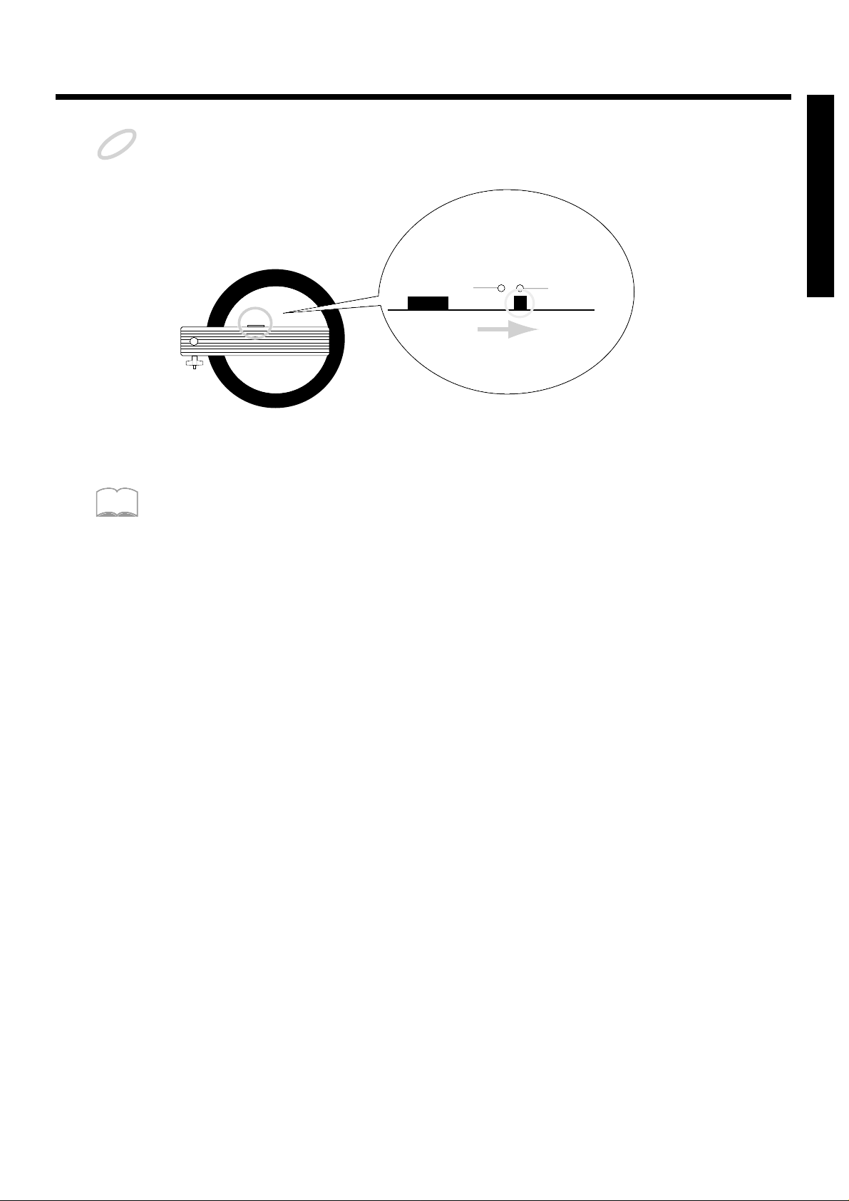
● M-512E DATA cards are equipped with a PROTECT
switch, which when turned on protects your data from
accidental erasure. It is recommended that the switch be
kept at the ON position, and switched to OFF only at the
times you wish to write new data onto the card.
● When the battery in an M-512E DATA card is nearly
worn out, the message below will be shown in the display. Refer to the instructions supplied with the DATA
card and promptly replace the battery to avoid the loss of
the data on it.
“MEMORY CARD Battery Low ! Please Change !”
● Carefully insert the DATA card all the way in—until it is
firmly in place.
● Never touch the terminals of the DATA card. Also, avoid
getting the terminals dirty.
OffOn
Important notes
17
In addition to the items listed under “IMPORTANT SAFETY INSTRUCTIONS” and
“USING THE UNIT SAFELY” on pages 2–4, please read and observe the following:
Page 18
Operations common to all aspects of operating the TD-10 are covered below.
■ Saving your settings
For operations within the TD-10, there is no procedure for “saving settings.” When you modify the
value of a setting, the new value is automatically saved as soon as you make the change.
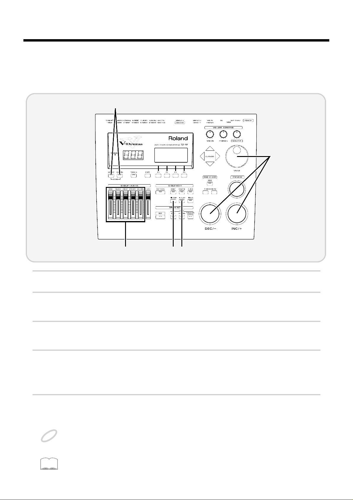
■ Buttons, sliders and knobs
Buttons, sliders and knobs on the front panel will be printed in square brackets [ ]; e.g., [SETUP].
■ Cursor
fig.00-003e
Cursor refers to the highlighted characters indicating an on-screen item that can be set. If the screen
contains more than one item that can be set, use the [CURSOR] buttons to move it to the item that
you wish to set.
fig.00-003a
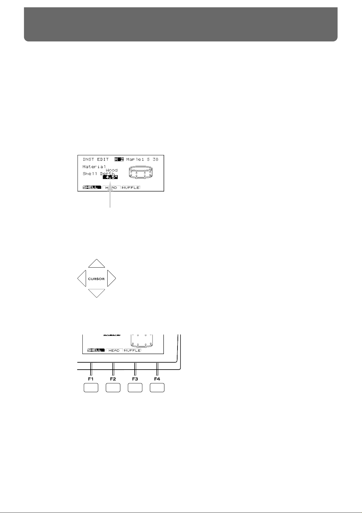
■ Function buttons ([F1]–[F4])
fig.00-004
The [F1]–[F4] buttons are called the “function buttons.” The bottom part of the display will show the
names of the functions available for [F1]–[F4]. For example, if this owner’s manual makes reference
to [INST]-[F1 (SHELL)], press [INST] , and then press [F1] (in this case, “SHELL” is displayed above
[F1]).
Cursor
About button operations and the screen displays
18
Page 19
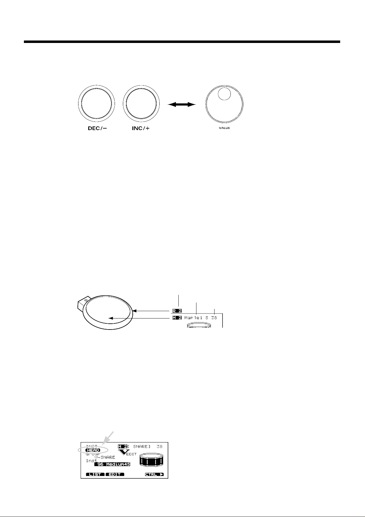
■ How to modify settings
fig.00-005e
[INC] and [DEC] (referred to in this manual as [INC/DEC]) and the VALUE dial are both used to
modify the values of settings. The two methods have the following advantages.
[INC/DEC]
• Each time [INC] is pressed, the value increases. Each time [DEC] is pressed, the value decreases.
This is convenient for fine adjustments.
• When making an on/off setting, [INC] will turn the setting on and [DEC] will turn it off.
• If you hold down [INC] and press [DEC], the value will increase rapidly. If you hold down [DEC]
and press [INC] the value will decrease rapidly.
VALUE dial
Since the dial allows you to make major changes to the value at once, it’s a convenient way to make
broad adjustments to a parameter quickly.
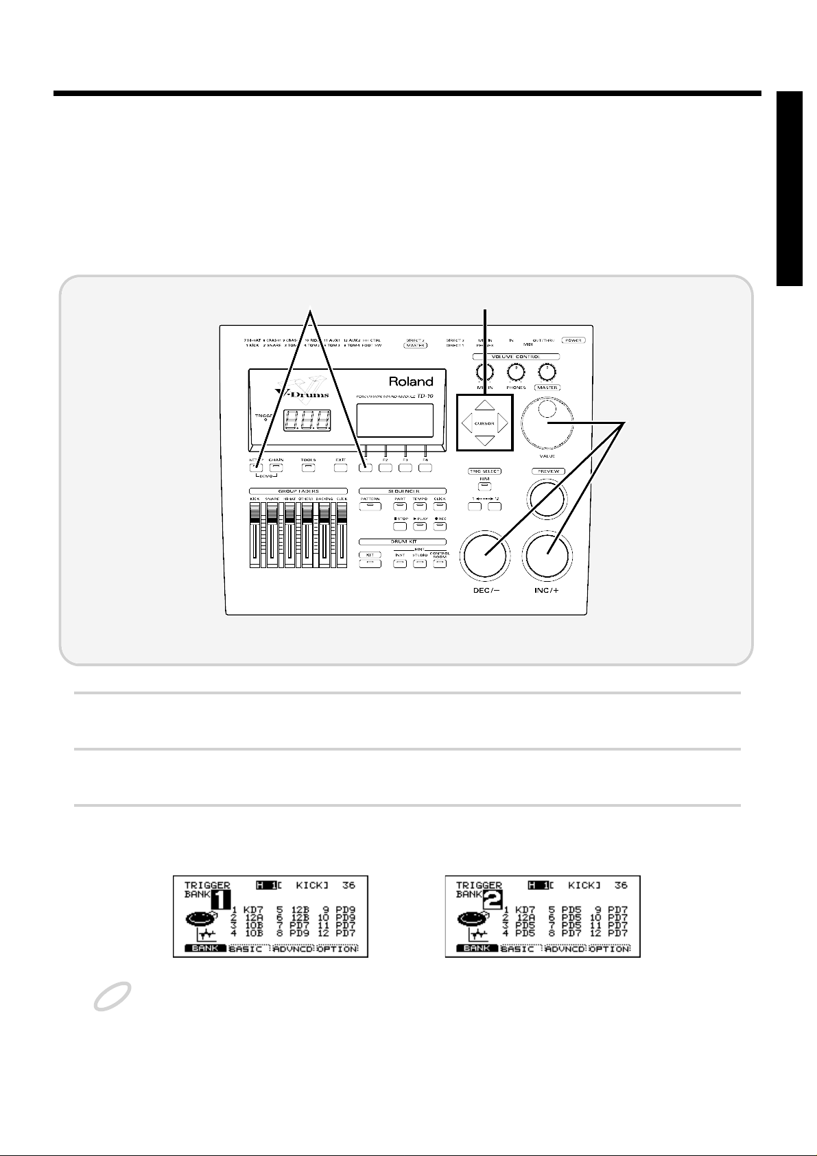
■ About the upper right of the screen display
fig.00-006e
In pages that allow you to make settings for each pad, you can strike the desired pad to see the setting page for that pad. At this time, the upper right of the display will show the number of the trigger jack to which the selected pad is connected, the instrument that it is using, and the MIDI note
number. The first character (“H” or “R”) indicates whether the head or the rim of the pad is selected.
The numerals at the right are the MIDI note number. You will need to know the MIDI note number
when using the TD-10 as a MIDI sound module.
The “H” or “R” display will indicate whether the head or rim will sound when you press the
Preview button. In cases where settings for the head and rim can be edited separately, the following
characters will also be displayed, letting you know the page in which you are.
fig.00-007
INC/DEC button VALUE dial
Trigger number
Instrument name (or Trigger name)
Rim
Head
MIDI note number
About button operations and the screen displays
19
Page 20
■ Selecting pads from the TD-10 front panel
fig.00-008
The trigger select buttons ([TRIG SELECT]) are used when you wish to select a sound for editing
from the front panel of the TD-10, rather than by striking a pad as explained above. You can use
these buttons to select a trigger number and edit the settings.
When you press the button marked “1,” the next lower-numbered trigger will be selected. When
you press the button marked “12,” the next higher-numbered trigger will be selected.
When using a PD-7, PD-9 or PD-120, the rim button ([RIM]) lets you specify whether you are making settings for the head or the rim. When the [RIM] indicator is lit, the rim is selected.
By using these buttons in conjunction with the preview button, you can edit without pads connected
to the TD-10.
* Depending on the instrument selection, there will be no distinction between head and rim in some cases. For
details refer to p. 136.
■ About the Preset Drum Kits
When the instrument is shipped from the factory, drum kits 1–50 are already pre-loaded. Even if
you modify the settings of these drum kits, you can restore them to their factory settings at any time.
These drum kits are referred to as the Preset Drum Kits. For details, refer to p. 137.
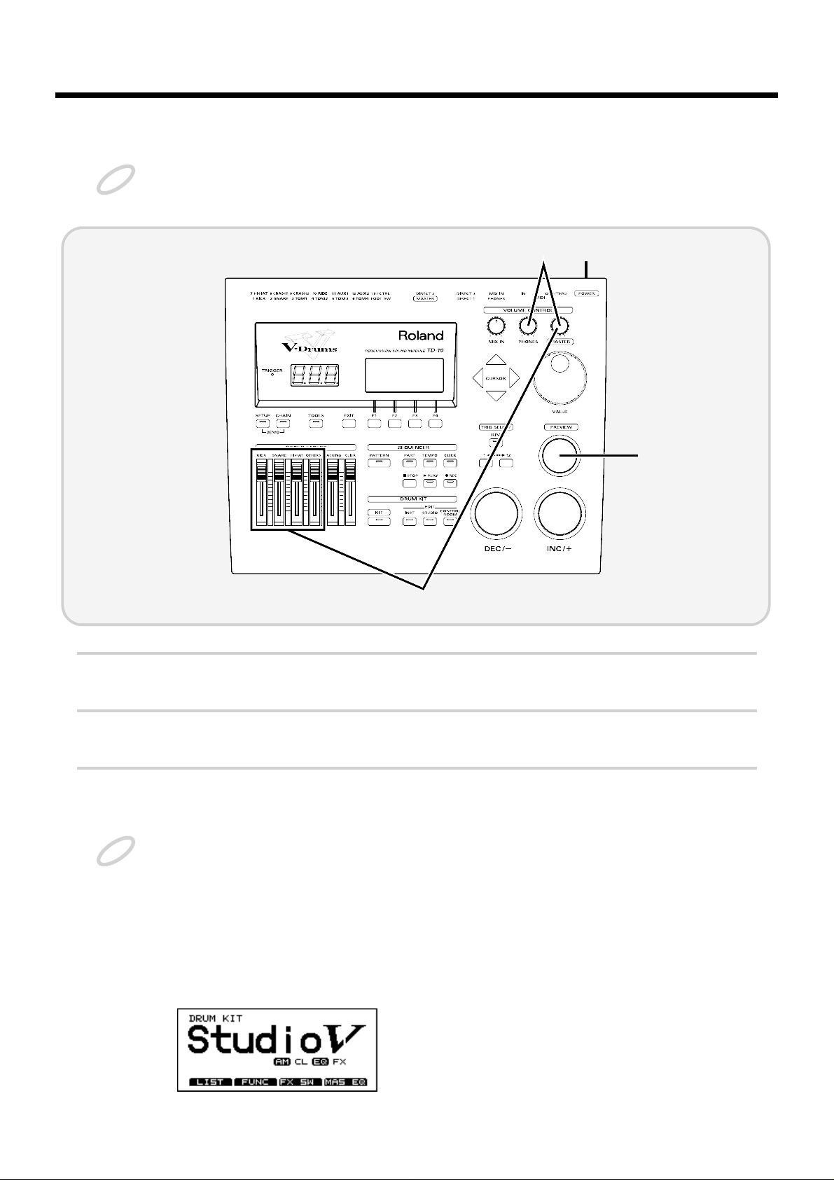
■ About the basic screen
fig.00-008ae
This screen is the TD-10’s basic screen, which will appear when you press [KIT].
In addition to the kit name, it displays the status of the memory card (p. 78), the effect on/off setting
(p. 79), and whether or not the kit is for brushes (p. 79) etc.
Screen
name
Drum kit
name
Effect on/off
Settings for brushes
About button operations and the screen displays
20
Page 21
Quick Start
Quick Start
21
Page 22
This section explains the connections and settings that you must make before playing. The explanations here are given, assuming that the TD-10 has its factory settings.
The TD-10 provides a function for restoring the factory settings. Refer to “Restoring the factory settings (INITIALIZE)” on p. 137.
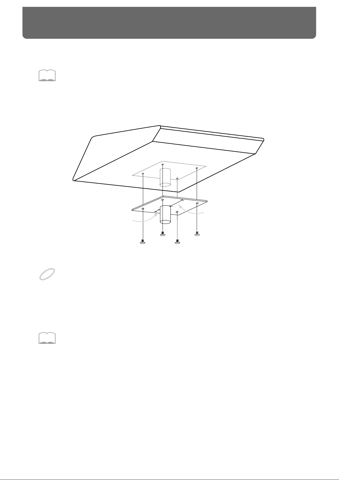
Mounting the TD-10 to the stand
Attach the stand holder (included with the optional MDS-7U/10) to the TD-10.
fig.00-009e
Using the included screws, attach it so that the unit is oriented as shown in the above diagram.
Use the included screws. Using other screws can cause damage.
Next, attach the TD-10 to the drum stand (MDS-7U/10).
For details on assembling the drum stand and attaching the TD-10, refer to the owner’s manual for
the drum stand (MDS-7U/10).
To attach the TD-10 to a cymbal stand (or the like), you may want to make use of the separately available
APC-33 All Purpose Clamp.
Make sure, though, that the cymbal stand you intend to use has pipes with a diameter of between 10.5 and 30
millimeters.
MEMO
Narrow
Wide
NOTE
MEMO
Before you begin playing
22
Page 23
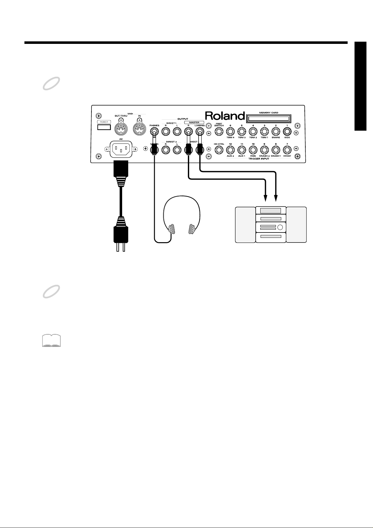
Connect your audio system or amp
To prevent malfunction and/or damage to speakers or other devices, always turn down the volume, and turn
off the power on all devices before making any connections.
fig.00-010e
Connect the rear panel MASTER L(MONO) and R jacks to your audio system or amps. If you will be
using headphones, connect them to the PHONES jack.
Be sure that the TD-10’s MASTER L and R jacks are connected respectively to the L and R of your audio system or amps.
In consideration of live performance situations, the headphone output is designed to produce a higher volume
than other electronic musical instruments. Extended listening at high volumes will damage your hearing, so
please pay attention to the volume adjustment.
At the factory settings, no sound will be output from the DIRECT 1, DIRECT 2 or DIRECT 3 jacks.
NOTE
to AC
power outlet
Stereo headphones
Power cord
Audio cable
Audio set, etc.
RL
NOTE
MEMO
Before you begin playing
23
Quick Start
Page 24
Connecting pads and pedals
Using the cables provided, connect your pads, hi-hat control pedals and kick trigger units as shown
in the above diagram. Special jacks are provided for the kick (KICK) and snare (SNARE), so make
the correct connections to these jacks.
fig.00-011e
Roland
Roland
TD-10 Rear panel
Before you begin playing
24
Page 25
If you are using a PD-7 or PD-9, move the polarity switch located on the back of the pad to the “-(Roland)”
position. When using a KD-7, either position will do.
fig.00-012
To have the most expressive performance, we recommend the use of the Roland pads (PD-5, PD-7, PD-9, PD100, PD-120) and kick trigger units (KD-7).
NOTE
PD-7, PD-9
OUTPUT POLARITY
+ - (Roland)
MEMO
Before you begin playing
25
Quick Start
Page 26
Turning on the power
Once the connections have been completed (p. 23, 24), turn on power to your various devices in the order specified. By turning on devices in the wrong order, you risk causing malfunction and/or damage to speakers and
other devices.
fig.00-013
1
Rotate [MASTER] and [PHONES] all the way to the left to turn down the volume.
2
Turn down the volume of the connected amp or audio system.
3
Turn on the POWER switch located on the rear panel of the TD-10.
Caution when turning on the power
● After turning on the power, do not press the hi-hat control pedal (FD-7) until the drum kit
name (see the following illustration) appears in the display.
If the pedal was pressed while the power was being turned on, hi-hat open/close operations cannot be performed correctly.
● After turning on the power, do not strike a pad until the drum kit name appears in the dis-
play.
Striking a pad while the power is being turned on will cause poor response when the pad is struck softly.
fig.00-037
NOTE
5
3
6
1
NOTE
Before you begin playing
26
Page 27
4
Turn on the power of the connected amp or audio system.
5
Raise the [GROUP FADERS] sliders to the maximum position, and adjust [MASTER] ([PHONES])
to the position shown in the diagram.
fig.00-014a
6
While striking [PREVIEW] with your finger, adjust the volume of the connected amp or audio system. If you are using headphones, gradually raise [PHONES] to adjust the volume.
The TD-10 will produce sound. The volume will depend on the force with which you struck [PRE-
VIEW].
You can use [TRIG SELECT] to select and audition the instrument for each pad.
■ To turn the power off ...
1
Make sure that the TD-10 volume controls and the connected external devices are turned to the
minimum position.
2
Turn off the power of the external devices.
3
Turn off the power of the TD-10.
If there is no sound when you strike [PREVIEW] ...
Check the following points.
· If you are using headphones, are they connected to the PHONES jack?
· If you are using an external amp, is it connected to the MASTER jacks? Are the
audio cables connected correctly to the input jacks of the external amp, etc.?
· Could there be a problem with the cables connected to the external amp?
· Are the input select settings of the external amp correct?
· Are the [GROUP FADERS] sliders lowered?
· Could the [PHONES] volume be too low?
· Could the [MASTER] volume be too low?
MEMO
Before you begin playing
27
Quick Start
Page 28
Listening to the internal demo playback
The TD-10 contains demo songs that demonstrate its sounds and expressive capabilities. The demo
song is a “rainbow” of 4 short songs, arranged as a medley. It plays back in “loop” (repeating)
mode, yet you can also listen, starting from any of 4 positions, accessed as follows:
fig.00-015
1
Set each of the [GROUP FADERS] sliders [KICK][SNARE][HI-HAT][OTHERS][BACKING] to the
same volume.
2
Hold down [SETUP] and press [CHAIN].
In this display, the cursor defaults to “Rock.”
3
Use [INC/DEC] or the VALUE dial to select the “section” number.
You can start listening from the beginning of any of the four sections.
4
Press [PLAY].
You can listen to the medley and it will continue to loop.
During playback, the [GROUP FADERS] function normally allowing you to mix the demo song as
you wish. (for more info on the [GROUP FADERS], see page 37.)
5
Press [STOP] to stop playback.
Once you are through listening to the demos, press [EXIT] to return to the “DRUM KIT” page.
All rights reserved. Unauthorized use of this material for purposes other than private, personal enjoyment is a
violation of applicable laws.
No data for the music that is played will be output from MIDI OUT/THRU.
Drum kit 39–42 are used in the Demo Song.
For details of the Demo Song, refer to page 179.
2
5 4
1
3
NOTE
MEMO
Before you begin playing
28
Page 29
Specify the pads that the TD-10 will use
In order for the TD-10 to accurately receive trigger signals from each pad, you must specify the type of
pad that is connected to each TRIGGER INPUT jack.
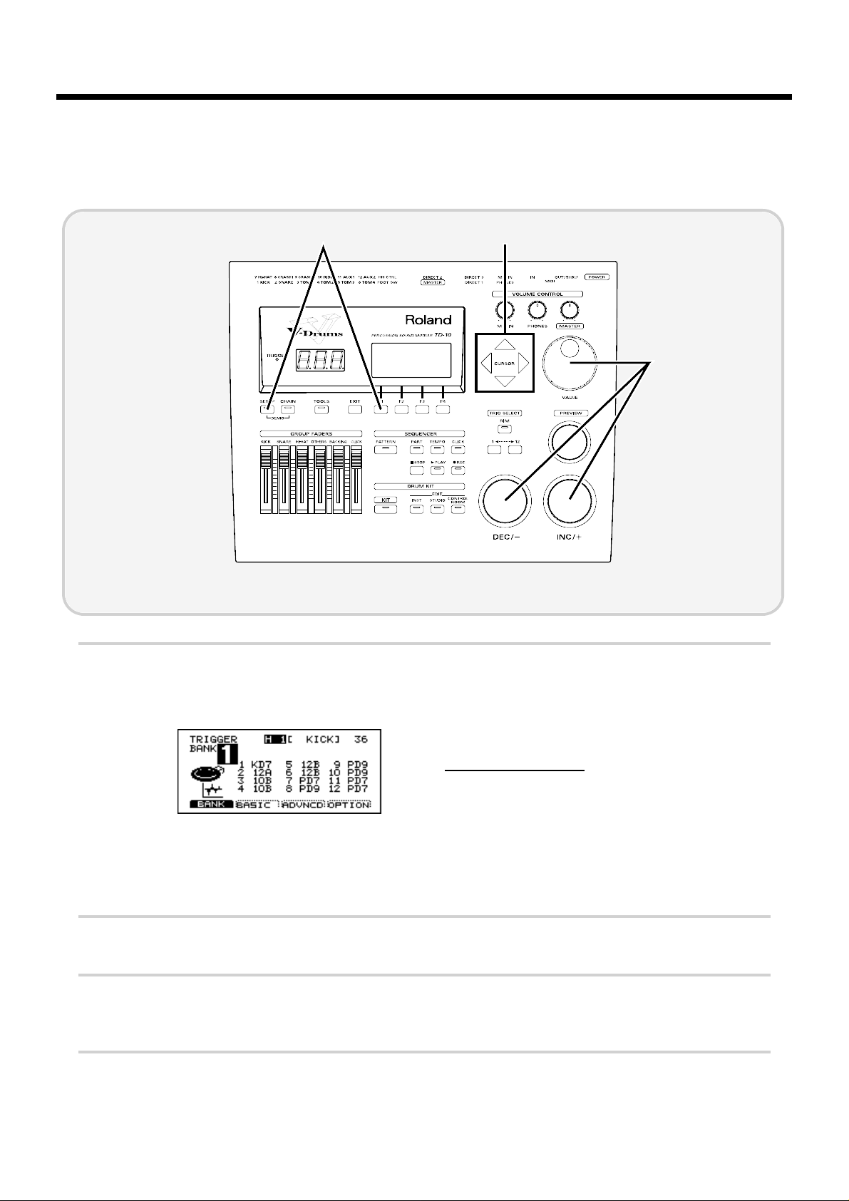
■ If you have purchased the “V-Basic Kit” or “V-Standard Kit”
Trigger settings for the V-Basic Kit or the V-Standard Kit are provided, so you can call up and select
them.
fig.00-016
1
Press [SETUP], press [F1 (TRIG)], and then press [F1 (BANK)].
2
Use [CURSOR] to move the cursor to the “BANK” number.
3
Use [INC/DEC] or the VALUE dial to make the setting.
V-Basic Kit: BANK 1 V-Standard Kit: BANK 2
If the settings have been modified and are different than the settings in the above diagram, use the Copy function to restore the factory settings (p. 137).
This completes settings for all pads of the V-Basic Kit or V-Standard Kit. If you are using a PD-100 or
PD-120, make settings for the head tension as explained on p. 31.
Once you have completed your settings, press [EXIT] enough times to get back to the “DRUM KIT” page.
1 2
3
NOTE
Before you begin playing
29
Quick Start
Page 30
■ If you have purchased the PD-5, PD-7, PD-9, PD-100 or PD-120
individually
Make the following settings for each pad.
fig.00-023
1
Press [SETUP], press [F1 (TRIG)], and then press [F1 (BANK)].
The following screen will appear:
fig.00-017
This screen shows a list of pad models that are specified
for each TRIGGER INPUT jack.
Display Pad name
PD5 PD-5
PD7 PD-7
PD9 PD-9
10A PD-100
12A PD-120
KD7 KD-7/KD-5
* For details on 10B and 12B, refer to p. 108.
2
Use [CURSOR] to move the cursor to a location other than “BANK.”
3
Strike the pad for which you wish to make settings.
The cursor will move to the edited value of the pad that you struck.
4
Use [INC/DEC] or the VALUE dial to select the model name of the pad.
This completes pad settings. If you are using a PD-100 or PD-120, make settings for the head tension
as explained in the following section.
1 2
4
Before you begin playing
30
Page 31

●Adjusting the head tension
For these pads, adjustments are required in order to regularize the tension of the head. Also, the ten-
sion of the head may change when the pad has been used for a long period. If this occurs, use the
following procedure to make adjustments as necessary.
fig.00-025
1
Make sure that the Trigger Type (pad model name) is set either to “10A” (PD-100) or to “12A” (PD-
120).
2
Press [SETUP], then press [F1 (TRIG)], and then press [F4 (OPTION)].
3
Strike the PD-100 or PD-120 for which you wish to make settings.
The setting page for the pad that you struck will appear.
fig.00-026
4
Use [CURSOR] to move the cursor to “Head Tension Adjustment.”
5
Use [INC/DEC] or the VALUE dial to make the setting.
With a setting of “Loose” it will be adjusted at a weaker tension, and with a setting of “Tight” it will
be adjusted at a stronger tension.
For now, set this to the medium value of “Normal.”
5
2 4
Before you begin playing
31
Quick Start
Page 32

6
On the head of the PD-100 or PD-120, accurately strike a location approximately 1 inch (3 cm) from
the tuning bolt.
fig.00-027e
The indicator in the lower right of the display will indicate how far off the adjustment is.
7
Use a tuning key (optional) to turn the all tuning bolt so that the indicator reaches the position shown
in the diagram.
fig.00-027ae
If the indicator is toward the right, turn the tuning key toward the left to loosen the tension. If the
indicator is toward the left, turn the tuning key toward the right to tighten the tension.
If the indicator moves greatly to the left or right, adjust the tension of the entire head before making this setting.
The head tension adjustment does not work correctly when the
“
SCAN TIME” (p. 111) setting is excessively
low. The “SCAN TIME” setting is automatically set to the most efficient values for each pad when you select
the “TRIGGER TYPE” (P.108). If you have changed the “SCAN TIME” setting, select the “TRIGGER
TYPE” again.
For details on adjusting the head tension, refer to the PD-100/120 owner’s manual.
Once you have completed your settings, press [EXIT] enough times to get back to the “DRUM KIT”
page.
1 inch (3 cm)
Strike here
Tuning bolt
Indicator
NOTE
MEMO
Before you begin playing
32
Page 33

■ Using triggers on an acoustic drum to play the TD-10
Set the trigger type to the drum trigger setting, and if notes are not sounded accurately, you’ll need
to make changes in the “advanced” mode of this section. For details, refer to “Detailed settings for
the trigger parameters (ADVNCD)” (p. 111) in the “Advanced Use.”
First refer to p. 142 and attach the drum trigger. When you have done so, make the following settings for each trigger.
fig.00-023
1
Press [SETUP], then press [F1 (TRIG)], and then press [F1 (BANK)].
The following screen will appear:
fig.00-017
This screen shows a list of the trigger types that are specified for each TRIGGER INPUT jack.
2
Use [CURSOR] to move the cursor to a location other than “BANK.”
3
Strike the drum (or press the kick pedal) for which you wish to make settings.
The cursor will move to the trigger number of the drum that you struck.
4
Use [INC/DEC] or the VALUE dial to specify the trigger type. Make the following settings for each
trigger.
“KIK”: Kick drum “TOM”: Tom
“SNR”: Snare drum “FLR”: Floor tom
Once you have completed your settings, press [EXIT] enough times to get back to the “DRUM KIT”
page.
1 2
4
Before you begin playing
33
Quick Start
Page 34

Check the settings
This completes the settings. Strike the pads/drums and verify that the appropriate instrument
sounds correctly. If not, check the settings once again, and refer to “Troubleshooting connections
and settings” on p. 45.
Before you begin playing
34
Page 35

Concerning the performance & expressiveness of
the pads
This section introduces various performance functions that will help you perform more expressively
on the pads.
Some of these playing techniques and functions are unique to the TD-10, so please be sure to read
this section in order take full advantage of the TD-10’s capabilities.
■ Rim shots
By using the rim, you can play two types of sound from one pad. This can be done with a PD-7, PD9 and PD-120.
fig.00-030e
To play a rim shot, you must strike both the head (center area) and the rim (outer edge) of the pad
simultaneously. There will be no sound if you strike only the rim. When you play a rim shot, the
instrument assigned to the rim will sound.
When specifying the rim during editing, you will also need to strike the head and rim simultaneously.
Important: The rim function of the PD-120 ONLY works when connected to trigger input 2 (SNARE). If
you desire rim sounds for the toms etc., please use a PD-7 or PD-9.
■ Choking
This function simulates the muting of a cymbal and can be done with a PD-7 or PD-9.
fig.00-031
By striking a pad and then squeeze the rim portion of the pad while the note is still sounding, you
can mute the sounding note; a performance technique known as choking.
Pad
Rim of the pad
Rim shotNormal shot
Pad
NOTE
For a better performance
35
Quick Start
Page 36

■ Positional sensing
This function simulates movement across the snare drum head or ride cymbal surface. A PD-7, PD9, PD-100 or PD-120 can be used when connected to trigger jacks number 2 or 10.
fig.00-032e
For the snare drum and ride cymbals, differences in striking position between the center of the head
and the rim area will produce a natural change in tone. When the PD-120 is used as a snare, changes
in tone and response will produce playability rivaling that of an acoustic drum.
■ Playing with brushes
The TD-10 allows you to play using brushes when using a PD-100 or PD-120 only . You can use techniques such as swishing or sweeping to trigger that type of sound, as with an acoustic drum. When
using brushes, you must select a drum kit that is intended for brush playing. Press [KIT], and select
a kit that has a symbol like the following at the lower right of the kit name.
fig.00-033
ONLY use nylon/plastic brushes. Metal brushes will damage the head and/or could pierce the fine mesh of the
head itself.
Of the preset drum kits, numbers 7 and 37 are for brush playing.
■ Hi-hat control pedal
A hi-hat control pedal can be used for the following performance techniques, giving you continuous
control from open to closed positions. This can be done with an FD-7.
fig.00-033a
Open hi-hat: Strike the pad without pressing the pedal.
Closed hi-hat: Strike the pad while pressing the pedal.
Pedalled closed: Step on the pedal to trigger the “foot close” hi-hat.
Pedalled open: Step on, and quickly release pedal to trigger the “foot open” hi-hat sound.
Tonal differences by strike location
NOTE
MEMO
FD-7
For a better performance
36
Page 37

TD-10 operating procedure
This section explains basic operation of the TD-10. Please try out each of these procedures.
■ Adjusting the volume
Adjusting the volume balance
For the kick drum, snare drum and hi-hat, use the [GROUP FADERS] sliders to adjust the volume.
Tom and cymbal, etc. are all adjusted as a group by [OTHERS].
Volume adjustments for each pad of the kit are made by the Control Room settings (p. 90).
fig.00-034
Adjusting the overall volume
Use [VOLUME CONTROL] to adjust the volume of the TD-10’s MASTER output jacks. Rotating it
clockwise increases volume, and rotating it counterclockwise decreases volume.
fig.00-035
[MASTER]: Adjusts the volume output from the MASTER OUT jacks.
[PHONES]: Adjusts the volume output from the headphone jack.
[MIX IN]: Adjusts the volume that is input from the MIX IN jack.
The input from MIX IN is output from the MASTER jacks and the PHONES jack (alternatively, only from the PHONES jack).
For a better performance
37
Quick Start
Page 38

■ Selecting a drum kit
fig.00-036
1
Press [KIT].
The following screen will appear:
fig.00-037
Each drum kit of the TD-10 is a collection of settings for the instrument assigned to each pad, settings for the room and microphones, mixer, effects and other parameters.
2
Use [INC/DEC] or the VALUE dial to select a kit.
The List display makes it easier to select a drum kit. In the above display, press [F1 (LIST)], and ten kit names
will appear in one screen, allowing you to select the desired kit. Press [F1 (PAGE <)] to move to the previous
page, or [F2 (PAGE >)] to move to the next page. In this display, you can select kits using [INC/DEC], the
VALUE dial, or [CURSOR].
fig.00-038
Press [EXIT] to return to the display page of step 1.
2
1
MEMO
For a better performance
38
Page 39

■ Adjusting the sensitivity of a pad
You may wish to adjust the sensitivity of the pads to accommodate your personal taste. In this sec-
tion we will explain the easiest way to adjust the TD-10’s sensitivity in order to get the best correla-
tion between your playing velocity (strength) and the response and volume of the sound.
fig.00-047
1
Press [SETUP], then press [F1 (TRIG)], and then press [F2 (BASIC)].
The following screen will appear:
2
Use [CURSOR] to move the cursor to “Sensitivity.”
3
Strike a pad to select the one needing sensitivity adjustment.
4
Use [INC/DEC] or the VALUE dial to adjust the sensitivity.
The numeric value at the cursor will change (within the range from 1 to 16). Lower sensitivity (lower
values) will mean that stronger strikes will not increase the volume very much. Conversely, higher sen-
sitivity will mean that loud volumes will be reached quickly as you play more strongly. In general, it is
best to set the sensitivity so that the indicator reaches the maximum position when you play with your
maximum dynamics.
Overall volume is an important element in adjusting the sensitivity of an electronic drum kit. In particular, if
you are listening at a low volume you may feel that there is too little change in volume, so you might raise the
sensitivity excessively without really needing to. Try playing at different volume levels (through amps or headphones) in order to fine tune the sensitivity. In order to make settings correctly, adjust the volume to an appropriate level.
21
4
Trigger indicator
NOTE
For a better performance
39
Quick Start
Page 40

■ Master equalizer
This is the master equalizer that is applied to the sound output from the MASTER OUT jacks. It
adjusts the balance of the low, mid, and high frequency ranges. Let’s try adjusting the GAIN (the
amount of boost).
fig.00-043
1
Press [KIT], and then press [F4 (MAS EQ)].
The following screen will appear:
fig.00-044
2
Use [F2]–[F4] or [CURSOR] to select the “GAIN” column.
[F2]: Low range (LOW)
[F3]: Middle range (MID)
[F4]: High range (HIGH)
[F1] functions as an equalizer on/off switch.
3
Use the VALUE dial to modify the value, and hear how the sound changes.
Press [EXIT] to return to the “DRUM KIT” display page.
2
3
1
MEMO
For a better performance
40
Page 41

■ Effect on/off
If you wish to compare your sounds “with” or “without” ambiance, individual compressors &
equalizers, or digital effects, here they can each be turned on/off for the entire kit.
fig.00-040
1
Press [KIT], and then press [F3 (FX SW)].
The following screen will appear:
fig.00-041
In this page, [F1]–[F4] act as on/off switches. For example, pressing [F1] will turn ambiance on/off.
AMBNCE (Ambience):The size of the room and the type of walls can be adjusted to modify the
sound.
COMP (Compressor): This is used to smooth volume peaks, preventing overload.
EQ (Equalizer): This adjusts the balance of the high, mid and low ranges.
EFFECT (Effect): This adds effects such as reverb or delay.
When these switches are turned off, effects will not apply, regardless of any other settings. Before using ambience or effects, make sure that these switches are turned on.
These settings can be made for each drum kit.
Press [EXIT] to return to the “DRUM KIT” display page.
1
NOTE
MEMO
For a better performance
41
Quick Start
Page 42

■ Help function
You can select a keyword for a specific operation and instantly view an explanation or the relative
setting page. For example if you wish to make settings for a function using a foot switch, select the
“FOOT SWITCH” keyword and press the button to access the appropriate setting page.
fig.00-045a
1
Press [TOOLS], and then press [F4 (HELP)].
The following screen (keyword list) will appear:
fig.00-046
2
Use [INC/DEC] or the VALUE dial to select a keyword.
3
Press [F4 (SELECT)], and an explanation of the function will appear.
4
If you wish to go to the setting page for that function, press [F4 (GO NOW)].
Once you have completed your settings, press [EXIT] enough times to get back to the “DRUM KIT” page.
2
1 3,4
For a better performance
42
Page 43

About expansion boards
Expansion boards (optional) are cards that allow you to upgrade the system and add new instruments and drum kits.
* Sound expansion boards for the Roland JV/XP series cannot be used.
For a better performance
43
Quick Start
The bottom panel of the TD-10 has a slot that allows expansion boards to be installed.
Install only the specified circuit board(s) (WAVE & SYSTEM
EXPANSION BOARD TDW series).
1. Always turn the TD-10 off and unplug the power cord
before attempting installation of the circuit board (WAVE
& SYSTEM EXPANSION BOARD TDW series).
2. Remove only the four screws as indicated below, and
open the cover located on the bottom of the TD-10.
fig.00-049ae
3. Check that the plastic board holders are positioned as
shown figure. Rotate them if necessary.
fig.00-049be
4. While positioning the holes on the board over the board
holders, carefully insert the connector on the board into
the socket on the TD-10. Make sure the connector is
securely connected, and that all three board holders project through the holes.
* Do not touch any of the printed circuit pathways or connection
terminals.
* Never use excessive force when installing a Expansion Board. If
it doesn’t fit properly on the first attempt, remove the board and
try again.
5. Use the Installation Tool supplied with the Expansion
board to turn the holders in the LOCK direction, so the
board will be fastened in place.
fig.00-049c
* When Expansion Board installation is complete, double-check
your work.
(To remove the Expansion board, turn the board holders in
the UNLOCK direction, and lift up the board using the provided tool. Remove the board and secure the cover plate.)
6. Secure the cover plate using the four screws removed in
step 2.
● Immediately turn the power off, and request servicing by your dealer or qualified Roland service personnel when:
• Objects (such as screws) have fallen into, or liquid has
been spilled on to the TD-10; or
• The TD-10 has been exposed to rain (or otherwise has
become wet); or
• The TD-10 does not appear to operate normally or
exhibits a marked change in performance.
Never open the bottom cover of the TD-10 by yourself.
● To avoid the risk of damage to internal components that
can be caused by static electricity, please carefully observe
the following whenever you handle the board.
• Before you touch the board, always first grasp a metal
object (such as a water pipe), so you are sure that any
static electricity you might have been carrying has been
discharged.
• When handling the board, grasp it only by its edges.
Avoid touching any of the electronic components or
connectors.
Removal screws
Board holder
Connector
Expansion board
LOCK
Page 44

À propos des cartes d’extension
(French language for Canadian Safety Standard)
Les cartes d’extension (optionnelles) sont des cartes qui vous permettent d’augmenter la puissance
de votre système et d’ajouter de nouveaux instruments ainsi que des batteries.
* Les cartes d’extension de son pour les séries JV/XP de Roland ne peuvent être utilisées.
For a better performance
44
N’installez que la ou les carte(s) de circuits imprimés spécifiée(s). (WAVE & SYSTEM EXPANSION BOARD série TDW)
Le panneau du dessous du TD-10 a un créneau permettant
l’installation des cartes d’extension.
1. Éteignez toujours le TD-10 et débranchez le câble élec-
trique avant toute tentative d’installation de carte de circuits imprimés (WAVE & SYSTEM EXPANSION BOARD
série TDW).
2. Enlevez seulement les quatre vis et ouvrez la plaque
située sous le TD-10.
fig.00-049ae
3. Veillez à ce que les supports en plastique pour la carte
soient positionnés tel qu’indiqué. Faites-les pivoter si
nécessaire.
fig.00-049bf
4. Pendant que vous alignez les trous de la carte au-dessus
des supports, insérez délicatement le connecteur sur la
carte dans la prise du TD-10. Assurez-vous que le connecteur est raccordé correctement et que les trois supports s’emboîtent bien dans les trous.
* Ne touchez pas à la carte de circuits imprimés ni à aucun des
terminaux de connexion.
* Ne forcez jamais excessivement lors de l’installation d’une carte
d’extension. Si elle ne s’ajuste pas correctement au premier
essai, enlevez-la et recommencez.
5. Pour tourner les supports en position LOCK (verrouillé),
utilisez l’outil d’installation de la carte d’extension fournie
à cet effet. De cette façon, la carte sera bien fixée à sa
place.
fig.00-049c
* Lorsque votre installation de la carte d’extension est terminée,
revérifiez-la.
(Pour enlever la carte d’extension, faites tourner les supports
dans la direction UNLOCK (déverrouillé) et soulevez la
carte en utilisant l’outil à cet effet. Retirez la carte et remettez
la plaque .)
6. Refermez la plaque en utilisant les quatre vis enlevées à
l’étape 2.
● Eteignez immédiatement l’unité, et contactez le
SAV de votre revendeur ou un service de maintenance Roland qualifié lorsque :
• Des objets (vis) sont tombés dans l’unité ou du liquide
s’est répandu à l’intérieur
• L’unité a été exposée à la pluie (ou d’ une façon ou
d’une autre a été mouillée)
• L’unité ne semble pas fanctionner normalement ou
montre une altération de ses performances.
N’ouvrez jamais vous-même le capot du dessous du TD-10.
● Pour éviter d’endommager les composants internes par
de l’électricité statique, suivez attentivement les régles cidessous lorsque vous maniez la carte.
• Avant de toucher la carte, saisissez toujours un objet
métallique (tel qu’un tuyau d’arrivée d’eau) pour être
sûr de vous décharger de toute électricité statique.
• Quand vous saisissez la carte, ne la prenez que par ses
côtés. Evitez de toucher ses composants électroniques
ou connecteures.
Vis
Support pour la carte
Prise
Carte d’extension
LOCK
Page 45

Troubleshooting connections and settings
This section will discuss points to check if you experience problems while making basic settings, and
how to solve those that occur easily when you are using electronic drums for the first time.
Before checking or modifying connections, be sure to turn off the power of all devices.
For troubleshooting of problems that occurred as a result of editing operations, etc., you will need to check your
editing, so please refer to “Troubleshooting” (p. 132) in the “Appendices.” Also refer to that section if you are
using acoustic drums to trigger the TD-10, or if you are using pads made by a manufacturer other than Roland.
NOTE
MEMO
For a better performance
45
Quick Start
■ No sound
First, make sure that connections have been made according
to the setup on p. 23–25, and then check the following
points.
●No sound when you strike [PREVIEW]
Make sure that the [GROUP FADERS] sliders are not lowered.
fig.00-034
●[PREVIEW] produces sound, but
striking the pads does not.
Check whether the trigger indicator (TRIGGER) lights when
you strike a pad. If it doesn’t light, check the connections of
the pad and TRIGGER INPUT jack.
fig.00-051
●You hear sound in the headphones
but not from the external amp, etc.
Check the connections with the external equipment,its volume, and make sure that the TD-10’s [MASTER] knob is not
turned down.
fig.00-052
■ The wrong pad sounds, or
other pads sound inadvertently
• Are you using the wrong TRIGGER INPUT jacks?
• Are the pads fixed firmly in place?
If the attachment of a pad has loosened, it may receive
vibrations when a different pad is struck, and trigger
sounds unintentionally.
• Is a high-volume speaker sounding nearby the pad?
Try changing the orientation of the speaker or the pad.
■ When a pad is struck softly, it
does not sound
• Did you touch a pad or press a pedal from the time that
the TD-10 was powered on until the kit name display
appeared?
When the power is turned on, the TD-10 checks the pads.
If pads are struck during this time, the check cannot be
performed correctly.
■ The volume is too small for the
force with which the pads are
struck
• Are you listening at an appropriate volume?
In the case of electronic drums, listening at low volumes
may give you the impression that the pad sensitivity is
low. If raising the volume (p. 37) does not correct this, then
try adjusting the sensitivity (p. 39).
If you are using a PD-5, PD-7, PD-9,
PD-100 or PD-120
You can make adjustments for the volume produced relative
to the playing velocity (striking force) on the pad. Refer to p.
39 and try making this adjustment.
Page 46

If you are using pads made by another manufacturer
If when using pads made by another manufacturer, they do
not perform satisfactorily, you will need to adjust the trigger
parameters. Refer to “Basic settings for the trigger parameters (BASIC)” (p. 109) in the “Advanced Use,” and make the
needed changes or settings.
■ Specific pads are too loud or
too soft
• If you are listening in monaural, use the MASTER L
(MONO) jack ONLY, and do not insert a plug into the R
jack.
• Are each of the [GROUP FADERS] sliders in an appropriate position?
Move all the faders to the same volume,then re-adjust for
the desired balance.
■ Rim shots do not sound
• Are you using a PD-7, PD-9 or PD-120 pad?
Rim shots cannot be played on other pads.
• Are you using a monaural cable to connect the pad with
the TD-10?
If so, only the head portion will trigger sound. Use the
stereo cable included with the PD-7, PD-9 or PD-120.
• Are the trigger type settings correct?
■ Rim shots do not sound cor-
rectly
• When playing on the PD-7 or PD-9, strike the rim and
head simultaneously. Simply striking the rim alone will
not produce sound.
• Are the trigger type settings correct?
• If you are using a PD-120 as the snare, check the “Rim
Sensitivity” setting (p.110).
■ Volume is low when you play
using brushes
• Since the impact of a brush is lower than the impact of a
stick, you need to use a drum kit that has trigger settings
geared for brushes, one displaying a symbol such as the
following in the lower right of the KIT display page.
fig.00-053
■ Strike location is not detected.
• Are the trigger type settings correct?
• When using a PD-100 or PD-120, is the head tension
adjusted correctly?
• When using a PD-7 or PD-9, is the Polarity Switch set to “(Roland)”?
• Strike location can be detected only for trigger number 2
(SNARE) and trigger number 10 (RIDE).
For a better performance
46
Page 47

How sounds are created on the V-drums
The TD-10 uses a completely new method for generating sounds called Variable Drum Modeling.
The concept of this method is to “model” the important parts or “character” that makes a drum
sound the way it does. This allows editing of parameters that were never available before, thus creating new and personalized sounds.
fig.00-054e
1. Instrument (INST)
The materials that make up the drums, their shape, and other elements.
2. Studio (STUDIO)
The type, size and construction material of the room in which the drums are played, positions of the
ambient mikes, and the type and position of the microphones used to pick up the instruments.
3. Control room (CONTROL ROOM)
Here, the finishing touches are made by changing mixer settings such as volume/pan/effect send
level/output assignment/EQ/Compressors and digital effects.
The V-drums concept focuses on these three major areas and three dedicated buttons [INST], [STUDIO] and [CONTROL ROOM] are provided for quick access so your creative aspirations can be
immediately translated into reality. As an interface concept for the user, this is also completely new.
Before you actually begin creating sounds, please read the following explanations of some of the
preset drum kits. They will lead you through some easy steps to become familiar with the features
of an acoustic kit, a kit for brushes, and an electronic kit.
Mixer
Compressor
Equalizer
Effect
Room ambience
Room, Microphone
Room type
Mike setting
Instrument
Drum shell
Drum head
Snares
Tuning
Muffling
Mixing
Features of the preset drum kits
47
Quick Start
Page 48

No.36: 70’s Rock drum kit
This is a rock drum kit with a deep and “fat” sound. Until now, this type of “fatness” could never be
created or edited in drum modules or samplers. However, since the TD-10 uses a model of an
acoustic drum that can be adjusted using the Variable Drum Modeling technology, you can create a
sound of your own and one that responds to your natural dynamics.
Let’s take a look at the instrument parameters of this kit. One of the parameters that creates the richness of the sound is “Shell Depth” (which adjusts the depth of the drum shell). Let’s experiment by
changing the shell depth of the snare drum.
fig.00-056
1
Press [KIT].
The “DRUM KIT” page will appear.
2
Use [INC/DEC] or the VALUE dial to select kit number 36.
fig.00-057
53
2,6
1
Features of the preset drum kits
48
Page 49

3
Press [INST], then [F2 (EDIT)], and then press [F1 (SHELL)].
The following screen will appear:
fig.00-058
4
Strike the pad that you are using as the snare.
The snare settings display page will appear. In this page you can select the materials and depth of
the drum shell.
fig.00-059
5
Use [CURSOR] to move the cursor to “Shell Depth.”
fig.00-060
6
Use [INC/DEC] or the VALUE dial to change the depth of the shell.
In order to produce a powerful sound, this preset has a setting of 8.0 inches, but let’s try changing
this to 3.5 inches.
fig.00-061
How does it sound? The character has changed considerably, and is much lighter. Strike a tom pad,
and try the same adjustment for it.
In order to make the same comparison on acoustic drums, you would two separate drums.
Furthermore, previous models of electronic drums had no way to make this adjustment. However
on the TD-10, such changes are made with simple front panel operations,letting you create the
desired sound in an instant.
Features of the preset drum kits
49
Quick Start
Page 50

No.37: Brush Kit
This is a kit for playing with brushes, something that was also not possible with any previous electronic drum system. Compared with stick playing, brush playing uses an extremely delicate trigger
signal, so we have provided a kit with special trigger settings. The studio and control room settings
are set to take advantage of this delicate character, and emphasize a natural feeling as if the kit were
being played right in front of the listener. Listen to what the effect settings are doing. To avoid
destroying the nuances of the original sound, effects are being used subtly, and do create a significant impact on the resonance and tone of the delicate sounds.
fig.00-064
1
Press [KIT].
The “DRUM KIT” display page will appear.
2
Use [INC/DEC] or the VALUE dial to select kit number 37.
fig.00-065
3
2
1
4
Features of the preset drum kits
50
Page 51

3
Press [F3 (FX SW)].
The following screen will appear:
fig.00-066
An indication of “ON” appears above each button [F1]–[F4], indicating that all effects are being
used.
4
Press [F1] and [F4].
Ambiance and Effect will be turned off.
fig.00-067
How does it sound? You will notice that the sound has suddenly lost its sense of depth.
Sounds that have a pronounced delicate character respond very sensitively to ambience and reverberation. In more advanced applications of these settings, you can control the character of ambiance
and reverb to simulate the exact acoustic space that you have in mind; for example, a “live” and
“spatial” character, while at the same muting some of the resonance.
Features of the preset drum kits
51
Quick Start
Page 52

No.38: Electronic drum kit
With this kit we can reproduce the electronic drums that were popular in the early 1980’s. Previous
drum sound modules did not provide for the creation and editing of the unique parameters of an
electronic drum. Since the TD-10 provides these parameters and also reproduces tonal changes
resulting from changes in velocity (striking force), it gives us powerful electronic sounds with great
potentials in today’s dance, hip-hop and rap music scenes.
Let’s experiment by changing the amount of pitch bend,a function that modifies pitch during the
decay (duration) of the sound, and is one feature that characterizes an electronic drum. The pitch
bend parameter specifies the amount of pitch change.
fig.00-070
1
Press [KIT].
The “DRUM KIT” page will appear.
2
Use [INC/DEC] or the VALUE dial to select kit number 38.
fig.00-071
5
2, 6
1 3
Features of the preset drum kits
52
Page 53

3
Press [INST], and then press [F2 (EDIT)].
The following screen will appear:
fig.00-072
4
Strike the pad that is being used as the tom.
The tom setting screen will appear.
5
Press [CURSOR] to move the cursor to “Bend.”
fig.00-073
6
While using [INC/DEC] or the VALUE dial to increase the pitch bend setting, strike the tom pad.
The pitch at the beginning of the note will become higher, and the effect will gradually become more
intense.
fig.00-074e
Time
Bend
0
127
amount of pitch change
Features of the preset drum kits
53
Quick Start
Page 54

In this section we will start with drum kit number 36, and take you through the process of creating
an entirely different kit. Kit number 36 is a distinctive kit intended for rock, but we will turn this
into a sharper and more natural-sounding drum kit that might be suitable for fusion, etc. When
effects are being used, it will be difficult to hear how the instruments really sound, so let’s begin by
turning off all the effects.
fig.00-075
1
Press [KIT].
The “DRUM KIT” page will appear.
2
Use [INC/DEC] or the VALUE dial to select kit number 36.
fig.00-076
3
Press [F3 (FX SW)].
The following screen will appear:
fig.00-077
4
Where there is an indication of “ON” above the [F1]–[F4] buttons, press the button to turn the indication “OFF.”
2
1
34
Modifying a drum kit
54
Page 55

[INST]: Creating drum sounds
The settings in this section are for the drums themselves, and they are concerned with the fundamental elements that determine the character of the sound. Via easy operations you can proceed
through the process of selecting an instrument, deciding its material and shape, and adjust the tuning, etc.
During the procedures described here, you can use [TRIG SELECT] to select triggers/sounds even if pads are
not connected, and use [PREVIEW] to audition the sound.
■ Selecting an instrument
fig.00-080
1
Press [INST].
The following screen will appear:
fig.00-081
2
Strike the pad whose instrument you wish to change.
The instrument select page for the specified pad will appear.
3
Use [INC/DEC] or the VALUE dial to select a different instrument. Strike the pad as you select different instruments to hear how they sound.
In this example, let’s use “106 Maple1 S” as the snare, and edit this to create our sound.
MEMO
3
1
Modifying a drum kit
55
Quick Start
Page 56

■ Modify the material and depth of the body
By changing the material of the instrument body and listening to the difference, you can find the
sound that you want. This is an editing method that is only possible on the TD-10. It’s just like
choosing between a variety of real snare drums.
Here, let’s modify the material and depth of the snare drum body.
fig.00-082
1
Press [INST], then press [F2 (EDIT)], and then [F1 (SHELL)].
2
Strike the pad being used for the snare.
The snare setting display page appears. Here, you can choose the material and depth of the body.
fig.00-083
3
Use [CURSOR] to move the cursor to “Material.”
3,5
1
4, 6
Modifying a drum kit
56
Page 57

4
Use [INC/DEC] or the VALUE dial to change the material of the body.
In this example, let’s change the setting from “Steel” to “Wood.” Of the three types, this will pro-
duce the warmest sound.
fig.00-084
This completes our selection of the body material. Next we will specify the depth of the body.
5
Use [CURSOR] to move the cursor to “Shell Depth.”
fig.00-085
6
Use [INC/DEC] or the VALUE dial to modify the depth of the body.
Since the current setting is a bit deep, let’s change this to “3.5".” Notice how the body resonance
decreases.
fig.00-086
Modifying a drum kit
57
Quick Start
Page 58

■ Change the material and tuning of the head
Here, let’s modify the type and tuning of the snare drum head.
fig.00-088
1
Press [INST], then press [F2 (EDIT)], and then press [F2 (HEAD)].
2
Strike the pad being used for the snare.
The snare setting page appears. Here, you can type and tuning of the head.
fig.00-089
3
Use [CURSOR] to move the cursor to “Head Type.”
4
Use [INC/DEC] or the VALUE dial to change the type of head.
In this example, let’s change the type from “Coated” to “PinStripe®.” The sound will become thicker,
with fewer overtones.
fig.00-090
* PinStripe is a registered trademark of Remo Inc. U.S.A.
3,5
4,6
1
Modifying a drum kit
58
Page 59

This completes the head material choice. Next we’ll tune of the head.
5
Use [CURSOR] to move the cursor to “Head Tuning.”
fig.00-091
6
Use [INC/DEC] or the VALUE dial to modify the tuning.
Here we will change the setting from “-30” to “0.”
Modifying a drum kit
59
Quick Start
Page 60

■ Adjust the muffling (muting) and snare strainer tension
You can add muffling to the snare drum or adjust the tension of the snare strainer to reduce unwanted overtones or resonances, creating a tighter sound. You can even turn the snares off!
fig.00-093
1
Press [INST], then press [F2 (EDIT)], and then press [F3 (MUFFLE)].
2
Strike the pad being used for the snare.
The snare setting page appear. Here, you can choose the muffling method and snare strainer tension.
fig.00-094
3
Use [CURSOR] to move the cursor to “Muffling.”
3,5
4,6
1
Modifying a drum kit
60
Page 61

4
Use [INC/DEC] or the VALUE dial to modify the setting.
For this example, select “Dougnuts1.” The sound will become somewhat more muted.
fig.00-095
This completes the muffling settings. Next we will adjust the tension of the strainer.
5
Use [CURSOR] to move the cursor to “Strainer Adj.”
fig.00-096
6
Use [INC/DEC] or the VALUE dial to modify the setting.
For this example, try “Loose.” Listen to the difference.
fig.00-097
Modifying a drum kit
61
Quick Start
Page 62
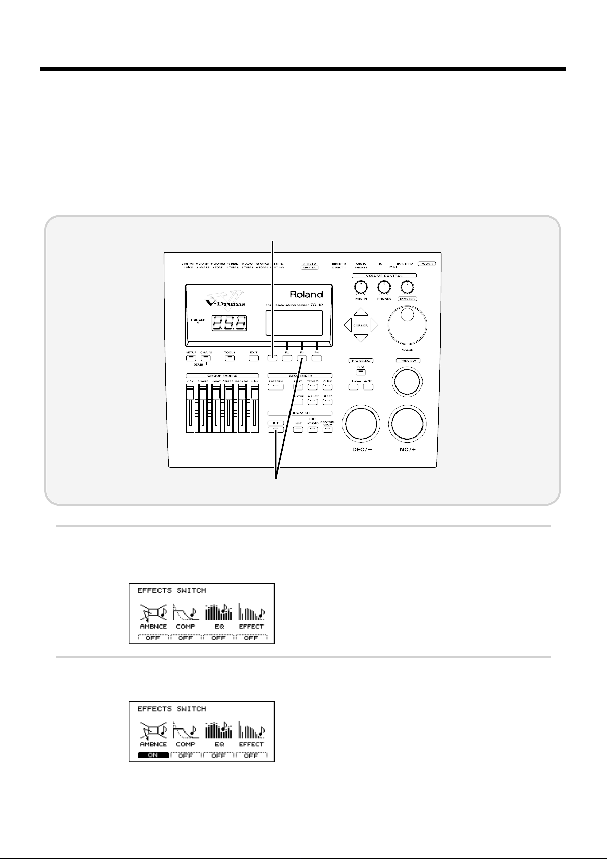
[STUDIO]: Adjusting the acoustics of the room
One very important element that affects the overall sound of a drum kit is the environment in which
the drums are placed. The same drums are capable of producing a very different sound, depending
on whether they are played in a conventional studio, or in a glass-walled room. Here you can make
such variations in room characteristics with the simple touch of a few buttons.
Here we will try editing Ambience, which is part of the “Studio” settings. First, turn on the
Ambiance that you turned off before selecting the instruments.
fig.00-098
1
Press [KIT], and then press [F3 (FX SW)].
The following screen will appear:
fig.00-099
2
Press [F1] to turn Ambiance “ON.”
fig.00-100
2
1
Modifying a drum kit
62
Page 63

■ Decide “where” the drums are played
You can choose locations for your drums from different types of rooms, a cave, a bathroom or even
the beach. You make this selection by “seeing” the icon that represents the actual acoustical environ-
ment.
The factory preset will be “Gymnasium.” Let’s change this to “Studio.” The resonance will change to
that of a more muted room.
fig.00-102
1
Press [STUDIO].
The currently selected studio settings will be displayed.
2
Use [INC/DEC] or the VALUE dial to select “Studio.”
fig.00-102a
2
1
Modifying a drum kit
63
Quick Start
Page 64

■ Change the size of the room
You can modify the “ambience” space by selecting one of five different room sizes.
fig.00-103a
1
Press [STUDIO], and then press [F2 (ROOM)].
The following screen will appear:
fig.00-103
2
Use [CURSOR] to move the cursor to “Room Size.”
3
Use [INC/DEC] or the VALUE dial to modify the setting.
Small sizes will produce a slight impression of ambient presence, and it will sound as though the
drums are being played right in front of your eyes. Larger sizes will produce a more “live” ambience. Adjust this setting as desired.
3
1
2
Modifying a drum kit
64
Page 65

[CONTROL ROOM]: Adding finishing touches to the sound
■ Using the equalizer to modify the sound
If you want the selected instrument to sound a little different, such as “a bit brighter” or “a bit
lighter,” etc., you can use the equalizer to make adjustments. The TD-10 has a 2-band (high and low)
equalizer for each instrument, and this can be used to fine tune each sound for the total blend of the
kit. This way, you can customize the contrast between individual sounds such as snare and kick for
example.
First, turn on the Equalizer that you turned off before selecting the instruments.
fig.00-104
1
Press [KIT], and then press [F3 (FX SW)].
The following screen will appear:
fig.00-105
2
Press [F3] to turn the equalizer “ON.”
fig.00-106
2
1
Modifying a drum kit
65
Quick Start
Page 66

In this example, let’s assume that we want to make the sound of the snare stand out.
fig.00-107
1
Press [CONTROL ROOM], press [F3 (EQ)], and then press [F4 (HIGH)]
The following screen will appear:
fig.00-108
2
Strike the pad being used for the snare.
The snare setting screen will appear.
3
Use [INC/DEC] or the VALUE dial to modify the value. For this example, adjust the setting to “+5.”
fig.00-108
3
1
Modifying a drum kit
66
Page 67

■ Adjusting the volume balance of the instruments
Now that we’ve used the equalizer to boost the high range, the snare sounds brighter. With this
change, however,the snare might stand out a bit too much. Let’s lower the volume to correct the balance.
fig.00-110
1
Set each of the [GROUP FADERS] sliders [KICK][SNARE][HI-HAT][OTHERS] to the same volume.
2
Press [CONTROL ROOM], press [F1 (MIXER)], and then press [F1 (VOLUME)].
The following screen will appear:
fig.00-111
3
Strike the pad that is being used for the snare.
The snare slider will be selected.
4
Use [INC/DEC] or the VALUE dial to lower the volume slightly.
When setting the volume, make sure that the group faders ([GROUP FADERS]) are all at the same level, and
use on-screen editing to adjust the volume balance. If you use this method, the same balance will be reproduced
each time you select that kit. It is best to use the group faders when you need to make temporary adjustments to
the volume. (they will NOT overwrite settings in the mixer page)
By using the simple procedures that have been introduced above, you can see how the simple and
friendly interface allows you to create a wide variety of drum kits, easily accessed by just pushing a
button.
4
1 2
MEMO
Modifying a drum kit
67
Quick Start
Page 68

This section will highlight things that are possible only with electronic musical instruments such as
the TD-10.
Perform with the on-board sequencer
The TD-10 contains a sequencer that can record and play back accompaniment tracks and/or drum
performances.
The sequencer contains built-in pattern performances (preset patterns). These patterns can be used
as a very helpful practice tool.
■ Playing back a preset pattern
Preset patterns 1–36 will playback several measures repeatedly until [STOP] is pressed. These patterns are convenient for drum practicing.
fig.00-114
1
Press [PATTERN].
The number of the currently selected pattern will be displayed.
fig.00-115
2
Use [INC/DEC] or the VALUE dial to select a pattern.
3
Press [PLAY].
The pattern will begin playing back. Press [STOP] to stop playback, and press it again to return to
the beginning of the pattern.
2
1 3
Examples and convenient tips
68
Page 69

■ Play the pads along with a preset pattern
When you have found a preset pattern that you like, you can play along with that pattern. While
sounding the click, adjust the volume balance of the drums, backing parts, and the click.
fig.00-117
1
Adjust the [BACKING] and [CLICK] [GROUP FADERS] lower than the other sliders.
2
Press [CLICK].
The click will begin sounding.
3
As described in “Playing back a preset pattern” (p. 68), play back the pattern.
4
Gradually raise the [BACKING] and [CLICK] GROUP FADER sliders to adjust the volume balance
with the drum kit.
21,4
Examples and convenient tips
69
Quick Start
Page 70

Drum Kit Chain—Selecting drum kits in the desired order
You can choose the order in which drum kits will be selected.
fig.00-120
1
Press [CHAIN], and then press [F1 (C.EDIT)].
The following screen will appear:
fig.00-121
In this screen, you can create a list to specify the order in which the drum kits will be selected.
2
Use [CURSOR] to move the cursor to the sequence order in which the drum kits will be selected—
the step number “1” located in the right of the screen.
fig.00-121a
3
Use [INC/DEC] or the VALUE dial to select the kit that will be selected first.
4
Use [CURSOR] to move the cursor to “2.”
3,5
7
2,41
Examples and convenient tips
70
Page 71

5
Use [INC/DEC] or the VALUE dial to select the kit that will be selected second.
6
In the same way, make settings for the third and subsequent kits.
fig.00-122
To delete an unwanted kit from a step, use [CURSOR] in the “CHAIN” page to select the kit, and then press
[F2 (DELETE)].
If you wish to add a kit between steps, press [F1 (INSERT)].
7
When you finish making the settings, press [EXIT].
You will return to the “DRUM KIT CHAIN” page.
fig.00-122a
In this page you can use [INC/DEC] to select drum kits in the specified order.
To turn off the Drum Kit Chain function, press [CHAIN] to make the button indicator go dark.
In addition, you can specify pads or foot switches that can be used to select drum kits easily, even while you
continue playing. For details refer to “Chapter 9. Operations using pads and foot switches” (p. 119) in the
“Advanced Use.”
MEMO
MEMO
Examples and convenient tips
71
Quick Start
Page 72

Using a foot switch to select kits
When an FS-5U foot switch (optional) is connected to the FOOT SWITCH jack, you can use it to
select kits, patterns, or as a play/stop button for patterns (p. 120).
fig.00-123e
The function that the foot switch will have can be selected by the “Mode” setting in the “FOOT SWITCH”
display (p. 120).
fig.00-123a
Using a pad to playback patterns
In addition to using pads to play drum sounds, it is also possible to make settings so that striking a
pad will start playback of a pattern.(with various possibilities) When this function is used, you can
(for example) strike a pad to start playback of a pattern, and then continue playing along with that
pattern. This is only possible with electronic drums!
Some of the preset drum kits use this function.
For details on the settings, refer to p. 119.
Foot switches
FS-5U
FS-5U
FS-5U
Foot switch cable PCS-31
MEMO
MEMO
Examples and convenient tips
72
Page 73

Using headphones to hear the click sound
If you want to listen to a click sound while you play (for example during practice or a live performance), you can make settings so that the click is heard only in the headphones, and is not output
from the OUTPUT jacks (MASTER).
fig.00-124
1
Press [CLICK], and then press [F2 (INST)].
The following screen will appear:
fig.00-125
2
Use [CURSOR] to move the cursor to “Output.”
3
Use [INC/DEC] or the VALUE dial to select “Phones Only.”
fig.00-126
21
3
Examples and convenient tips
73
Quick Start
Page 74

Using the TD-10 as a MIDI sound module
The TD-10 can also be used as a sound module for MIDI keyboards or sequencer. When used as a
MIDI sound module, the percussion group (p. 126) can be used so that 72 types of instrument can be
accessed simultaneously in addition to the sounds that are assigned to the 12 trigger inputs (pads).
In addition, three backing parts can be used as sound sources (each with its own individual MIDI
channel) as well as the drums. This means that a single TD-10 can be used as a four-part multi part
multi-timbral sound source with 56 voices of polyphony! For details refer to “Using the TD-10 as a
sound module” (p. 125).
Examples and convenient tips
74
Page 75

Advanced Use
75
Chapter 1
Chapter 2
Chapter 3
Chapter 4
Chapter 5
Chapter 6
Chapter 7
Chapter 8
Chapter 9
Chapter 10
Page 76

The TD-10 is a drum trigger interface and sound module, providing virtual reproduction of an actual drum set, allowing total control over all aspects of drum sound creation.
When electronic drums were first developed, the technology available was not as advanced as it is
today, so sounds were not really comparable with acoustic drums. However, many people appreciated electronic drums in their own right for their unique sound quality and character. The early electronic drum systems were fairly expensive, and not that easy to use in a wide musical context. Later,
the appearance of “samplers” (instruments using digital recording technology) brought great
advances in the quality of acoustic instrument simulations and editing potential of those sounds.
Although this technology was developed mostly for synthesizers, it was also applied to rhythm
machines and electronic drums though the operating procedures and the sound creating/editing
processes were simply carried over from synthesizers.
For many drummers, it became necessary to learn new and unfamiliar technical terms and methods
for processing sound, meaning that the “user friendliness” was considerably diminished.
The TD-10 V-drums offers access to the whole family of percussion sounds, including acoustic and
electronic drums, and percussion, and provides a control environment that is specially designed for
the drummer. This includes choosing your instrument, (out of over 600 sounds!) editing the sounds,
and a way to make sure they respond to your style of playing through the advanced and accurate
triggering response. You also have control of “where” the drums are played, the acoustics of that
environment, the types of microphones used on the drums and their positions and all details of the
final mixing process in the “control room.” In other words, the TD-10 alone is a complete drum production concept with a studio, effect units and a mixing console. There are 50 preset drum kits that
have been created in this manner, so you can get a feel of the TD-10’s potential once you have completed the basic setup.
How the V-drums system is organized
The V-drums system can be divided into the following two parts.
● Controllers such as pads and pedals on which you perform
● The sound module that produces sounds in response to your per-
formance on the pads or pedals
fig.01-02e
In this system, the TD-10 is the sound module.
When the TD-10 receives signals (trigger signals) received after pads are hit (or via MIDI) it plays
the corresponding instrumental sounds.
* The term “trigger signal” will appear frequently in this manual, so become familiar with the term as it will
will help you understand the explanations that follow (p. 172).
Sound module (TD-10)Controller
TRIGGER
INPUT Jacks
Instrument (instrumental sound)
Pad
OUTPUT jacks
PHONES jack
Chapter 1. Overview of the TD-10 V-drums
76
Page 77

How to select pads
When making settings, you can specify the pad in one of the following two ways.
■ Using pads to select the pad/sound for editing
Strike the head (the head and rim simultaneously) of the pad. The setting display for the pad you
struck will appear. Listen to the sound as you strike the head (the head and rim simultaneously),
and use [INC/DEC] or the VALUE dial to modify the setting.
■ Using the TD-10 to select the pad/sound for editing
Use the “1” button or “12” button located below [TRIG SELECT] to select a trigger signal(corresponds to the 12 trigger inputs). To edit the rim settings, press [RIM] to make the indicator light.
When using [PREVIEW] to audition a sound, use [INC/DEC] or the VALUE dial to modify the setting.
* When separate settings can be made for the head and the rim, a display such as the following will appear.
For details refer to p. 136.
fig.01-03
In this owner’s manual, a symbol such as the following will mark functions that can be set independently for
head and rim.
fig.(H)(R)
Head settings Rim settings
Chapter 1. Overview of the TD-10 V-drums
77
Chapter 1
Chapter 2
Chapter 3
Chapter 4
Chapter 5
Chapter 6
Chapter 7
Chapter 8
Chapter 9
Chapter 10
Page 78

Selecting a kit
Press [KIT], and the basic display page will appear. In this
page, you can use [INC/DEC],the VALUE dial or a foot
switch (optional) to select drum kits (p. 120).
fig.02-01
Area 1 in the above figure indicates whether the selected kit
contains settings for performance with sticks or for brushes.
To change this setting see “Making settings for brush performance” (p. 79). Area 2 indicates effect on/off settings for the
entire kit. Please refer to “Effect switches for the entire kit”
(p. 79). Area 3 will appear if a card is inserted into the TD-10.
If the card’s protect switch is on, a lock symbol will appear.
* To prevent data from being accidentally modified while you
play, it is a good idea to select this display page once you have
finished making settings.
Selecting kits from the list
display
Here you can select drum kits by accessing the full list of
available kits.
fig.02-02
Procedure
1. Press [KIT]-[F1 (LIST)].
The “DRUM KIT LIST” page will appear.
2. Use the VALUE dial, [INC/DEC], or [CURSOR] to select a
kit.
Function buttons
[F1 (PAGE <)]: The previous page of the list will appear.
[F2 (PAGE >)]: The next page of the list will appear.
Naming a kit
Each kit can be given a name of up to 8 characters.
fig.03-01
Procedure
1. Press [KIT]-[F2 (FUNC)]-[F4 (NAME)].
The “DRUM KIT NAME” page will appear.
2. Use the left/right [CURSOR] buttons to select the character that you wish to change.
The character at the blinking location is the one that can be
changed.
3. Use the VALUE dial, [INC/DEC], or [CURSOR] (up/down)
to change the character.
Characters can be selected in the order of the small characters displayed in the bottom of the screen.
Function buttons
In this page the [F1]–[F4] buttons can be used to perform the
following convenient functions for entering characters.
[F1 (INSERT)]: All characters to the right of the cursor will
be moved to the right.
[F2 (DELETE)]: The character at the cursor location will be
deleted, and all characters to the right of the
cursor will be moved to the left.
[F3 (SPACE)]: A blank space will be inserted at the cursor
location.
[F4 (CHAR)]: Cycle between uppercase/lowercase/sym-
bols.
2
1
3
Chapter 2. Settings for the entire drum kit
78
Page 79

Making settings for brush
performance
For each kit you can specify whether sticks or brushes will
be used. When the trigger setting is set to “brush,” pad sensitivity will be higher. Each kit has settings for sticks and for
brushes, and the brush settings can be selected as follows.
fig.03-02
Procedure
1. Press [KIT]-[F2 (FUNC)]-[F3 (SELECT)].
The “SELECT” page will appear.
2. Use [INC/DEC] or the VALUE dial to select “Brushes.”
The settings for brush performance will be selected.
* Preset drum kits for brushes are already set for brush perfor-
mance. The setting discussed here is necessary when you wish to
modify a kit that was created for stick performance in order to
play with brushes. If you wish to create a new brush kit, it’s simpler to copy an existing one and then edit it as you wish.
* The setting you make here can also be viewed in the drum kit
name page (“DRUM KIT”).
* When performing brush swish/sweeping, the following condi-
tions must also be met in addition to the above setting.
Trigger jack 2 must be used. (for the snare drum)
PD-120 or PD-100 pads must be used.
Make sure that you are using instrument number 113 “Brush1
S,” number 114 “Brush2 S” or 115 “BrushTmbS.”
Effect switches for the
entire kit
Ambience, compressors, equalizers, and digital effects can
be turned on/off for the entire kit. This gives you a great
way to “compare” your sounds with or without those functions.
Procedure
1. Press [KIT]-[F3 (FX SW)].
The “EFFECTS SWITCH” page will appear.
2. Each time you press a function button [F1]–[F4], the corresponding effect will be switched on/off.
Function buttons
[F1 (AMBNCE)]: Ambience on/off switch
[F2 (COMP)]: Compressor on/off switch
[F3 (EQ)]: Equalizers on/off switch
[F4 (EFFECT)]: Effect on/off switch
* The settings made here can also be seen in the drum kit name
page (“DRUM KIT”).
fig.03-02ae
On Off
Chapter 2. Settings for the entire drum kit
79
Chapter 1
Chapter 2
Chapter 3
Chapter 4
Chapter 5
Chapter 6
Chapter 7
Chapter 8
Chapter 9
Chapter 10
Page 80

Here you can edit the instruments.(i.e. snare drum kick etc.)
The TD-10 provides separate parameters for editing acoustic
or electronic drum sounds.
Selecting an instrument
On the TD-10, each sound,is referred to as an “instrument”
(INST). You’ll begin the sound-creating procedure by selecting the desired instruments.
fig.04-01
Procedure
(Example) Changing the snare
1. Press [INST].
The “INST” page will appear.
2. Strike the snare pad.
The name of the instrument being triggered by the snare pad
will appear at “Inst.” The “type” of the currently selected
instrument will appear at “Group.”
3. Use [INC/DEC] or the VALUE dial to select an instrument.
* There are instruments that cannot be selected There are some
instrument combinations that cannot be selected within the
same kit, or with certain trigger inputs. The V-EDIT process is
not available for all instruments (p. 136).
Selecting instruments
from the list display
Here you can choose the sound from the list of all instruments.
fig.04-02
Procedure
1. Press [INST]-[F1 (LIST)].
The “INST LIST” page will appear.
2. Strike the pad whose instrument you wish to change.
The setting page for the pad you struck will appear. The cursor will be at the name of the currently selected instrument.
3. Use the VALUE dial, [INC/DEC] or [CURSOR] to select
an instrument.
4. After you have selected an instrument, press [EXIT].
You will return to the “INST” page.
Function buttons
[F1 (PAGE <)]: The previous page of the list will appear.
[F2 (PAGE >)]: The next page of the list will appear.
You can also use the Function Key to scroll through the
instrument list at a higher speed.
To advance quickly Hold down [F2 (PAGE >)] and
press [F1 (PAGE <)]
To move in reverse quickly Hold down [F1 (PAGE <)] and
press [F2 (PAGE >)]
* Instruments which cannot be selected for specific triggers are
indicated by a horizontal line as in the following diagram.
fig.04-03e
Instruments which cannot be selected
Chapter 3. Instrument settings
80
Page 81

Editing an acoustic drum kit (V-EDIT)
● V-EDIT and EDIT
Editing procedure for an acoustic snare, kick and tom drums will differ depending on the type of
instrument and the TRIGGER INPUT jack that you are using.
1.V-EDIT lets you use all the editing capability of the TD-10
2.EDIT lets you edit only the two parameters Pitch and Decay
● VERY IMPORTANT!! When V-EDIT can be used
“V-EDIT” will appear ONLY when using trigger inputs 1–6 and an instrument from instrument
groups “V-KICK”, “V-SNARE”, or “V-TOM.” (A “V-EDIT” symbol will appear in the setting page.)
When an instrument from another instrument group is assigned, only Pitch and Decay can be edited. So if you assign a “V” type sound to an input other than 1-6, you cannot use the V-Edit parameters.
For details on assigning instruments, refer to p. 136.
The parameters available in V-EDIT will differ depending on the trigger input and instrument
selected. The following parameters can be edited.
Trigger Shell Material Shell Depth Head Type Head Tuning Muffling Strainer Adj.
1 (KICK) - o o o o 2 (SNARE) o o o o o o
3–6 (TOM) - o o o o -
o: Can be set - : Cannot be set
■ Selecting the shell material
Changing the material of the snare drum shell produces a different tone. You can select one of three
materials: wood, steel and brass.
fig.04-04
Instruments that can be edited
Snare only
Procedure
1. Press [INST]-[F2 (EDIT)]-[F1 (SHELL)].
The “INST EDIT” page will appear.
2. Strike the snare pad.
The snare setting page will appear.
3. Use [CURSOR] to move the cursor to “Material.”
4. Use [INC/DEC] or the VALUE dial to make the setting.
Parameters
Material: Wood, Steel, Brass
Wood: Wood body. This produces a natural and mellow sound.
Steel: Steel body. This produces a sound with metallic resonance.
Brass: Brass body. This produces the unique resonance of brass.
Chapter 3. Instrument settings
81
Chapter 1
Chapter 2
Chapter 3
Chapter 4
Chapter 5
Chapter 6
Chapter 7
Chapter 8
Chapter 9
Chapter 10
Page 82

■ Changing the shell depth
Changing the depth of the drum shell will change the tone.
With the snare drum, the depth can be changed over 39
steps, from 1 to 20 inches! Making the shell deeper will
increase the richness of the low range, and make the sound
more “fat”.
fig.04-05
Instruments that can be edited
Kick, Snare, Tom
Procedure
1. Press [INST]-[F2 (EDIT)]-[F1 (SHELL)].
The “INST EDIT” page will appear.
2. Strike the pad that you wish to edit.
The setting page for the pad you struck will appear.
3. Use [CURSOR] to move the cursor to “Shell Depth.”
4. Use [INC/DEC] or the VALUE dial to make the setting.
Parameters
Shell Depth: Normal, Deep (Kick)
1–20 inch (39 steps) (Snare)
Normal, Deep (Tom)
■ Selecting the head material
Changing the “type” of drum head will affect aspects of
attack and tone. You can choose from three type of heads:
Clear, Coated, and PinStripe
®
fig.04-06
Instruments that can be edited
Kick, Snare, Tom
Procedure
1. Press [INST]-[F2 (EDIT)]-[HEAD(F2)].
The “INST EDIT” page will appear.
2. Strike the pad that you wish to edit.
The setting page for the pad you struck will appear.
3. Use [CURSOR] to move the cursor to “Head Type.”
4. Use [INC/DEC] or the VALUE dial to make the setting.
Parameters
Head Type: Clear, Coated, PinStripe
Clear: A single transparent head.
Coated: The most commonly used type of head.
PinStripe
®
: Characterized by a rich medium and low range
“color.”
* PinStripe is a registered trademark of Remo Inc. U.S.A.
■ Tuning the head
Here you can tune the drum head very accurately.
fig.04-07
Instruments that can be edited
Kick, Snare, Tom
Procedure
1. Press [INST]-[F2 (EDIT)]-[F2 (HEAD)].
The “INST EDIT” page will appear.
2. Strike the pad that you wish to edit.
The setting page for the pad you struck will appear.
3. Use [CURSOR] to move the cursor to “Head Tuning.”
4. Use [INC/DEC] or the VALUE dial to make the setting.
Parameters
Head Tuning: -480–+480 (-4–+4 octaves)
* For some instruments, raising or lowering the value beyond a
certain point may not produce further change.
Chapter 3. Instrument settings
82
Page 83

■ Muffling settings (muting)
You can literally apply tape or “rings” to dampen the overtones.
fig.04-08
Instruments that can be edited
Snare, Kick, Tom
Procedure
1. Press [INST]-[F2 (EDIT)]-[F3 (MUFFLE)].
The “INST EDIT” page will appear.
2. Strike the pad that you wish to edit.
The setting page for the pad you struck will appear.
3. Use [CURSOR] to move the cursor to “Muffling.”
4. Use [INC/DEC] or the VALUE dial to make the setting.
Parameters
Muffling: OFF, Tape 1, Tape 2, Blanket, Weight (Kick)
OFF, Tape 1, Tape 2, Doughnuts 1, Doughnuts 2
(Snare)
OFF, Tape 1, Tape 2, Felt 1, Felt 2 (Tom)
OFF: No muffling.
Tape 1: one piece of tape.
Tape 2: two pieces of tape.
Blanket: Muffled by placing a blanket inside the kick
drum.
Weight: Blanket with a weight on top.
Doughnuts 1: common “ring” type mute.
Doughnuts 2: common “ring” type mute with stronger muf-
fling of overtones.
Felt 1: Conventional felt type mute.
Felt 2: Conventional felt type mute with more pres-
sure on the head.
■ Adjusting the Snare strainer
tension
The amount of contact between the bottom head and the
snares themselves can be adjusted to change the tone just
like with a real acoustic drum. You have a choice between
one of three tensions: Loose, Medium or Tight or you can
turn the snares OFF.
fig.04-09
Instruments that can be edited
Snare only
Procedure
1. Press [INST]-[F2 (EDIT)]-[F3 (MUFFLE)].
The “INST EDIT” page will appear.
2. Strike the snare pad.
The snare setting page will appear.
3. Use [CURSOR] to move the cursor to “Strainer Adj.”
4. Use [INC/DEC] or the VALUE dial to make the setting.
Parameters
Strainer Adj.: OFF, Loose, Medium, Tight
OFF: The sound with no snares.
Loose, Medium, Tight:
The strainer tension becomes progressively stronger.
Chapter 3. Instrument settings
83
Chapter 1
Chapter 2
Chapter 3
Chapter 4
Chapter 5
Chapter 6
Chapter 7
Chapter 8
Chapter 9
Chapter 10
Page 84

Editing an electronic
drum kit (V-EDIT)
Electronic drum sounds consist of “tone” and “noise.” These
instruments can be assigned only to specific trigger inputs.
For details on instrument assignments, refer to p. 136.
* With electronic drums, selecting an instrument for the head will
assign the same instrument to the rim. It is not possible to
change the rim to a different instrument.
fig.04-10
IMPORTANT: Instruments that can be used for specific trigger inputs Instruments from the “ELEC” instrument group
can be used ONLY with trigger inputs 1–6. Example: An
Electronic Kick can only be used with the trigger input (1)
dedicated for the Kick.
Procedure
1. Press [INST].
The “INST” page will appear.
2. Strike a pad that is connected to a TRIGGER INPUT jack
(1-6).
The setting page for the pad you struck will appear.
3. Use [INC/DEC] or the VALUE dial to select an instruments from the “ELEC” instrument group.
4. Press [F2 (EDIT)].
The setting page for the selected instrument will appear.
5. Use [CURSOR] to move the cursor to the parameter that
you wish to set.
* You can also use the [F1]–[F4] buttons to select parameters.
[F1]: Atk
[F2]: Each time the button is pressed, Tone or Noi will be
selected.
[F3]: Each time the button is pressed, Dcy or Bal will be
selected.
[F4]: Bend
6. Use [INC/DEC] or the VALUE dial to make the setting.
Parameters
Instruments from the “ELECTRONIC” instrument group
provide the following parameters.
Atk (Attack Level ): 0–127
Adjusts the volume of the attack (the beginning of the
sound).
Tone (Tone Pitch ): 0–127
Adjusts the pitch of the “tone” component.
Noi (Noise Pitch): 0–127
Adjusts the pitch of the “noise” component.
Dcy (Decay): 0–127
Adjusts the decay time of the sound.
Bal (Noise Tone Balance): 0–127
Adjusts the volume balance between the “noise” and “tone”
components.
Bend (Pitch Bend): 0–127
Adjusts the extent of the pitch change that occurs during the
sound. This setting adjusts the pitch at which the sound
begins.
fig.00-074e
Time
Bend
0
127
amount of pitch change
Chapter 3. Instrument settings
84
Page 85

Editing a TR-808/909 (V-EDIT)
This simulates a Roland “TR-808” or “TR-909” Rhythm Composer. Only instruments specified for
each trigger input can be selected. For details on instrument assignments, refer to p. 136.
* For instruments in the TR-808/909 groups, selecting an instrument for the head will assigns the same
instrument for the rim. It’s not possible to change the rim to a different instrument.
fig.04-12
Instruments and parameters usable for each trigger input
Instruments in the “TR-808” or “TR-909” instrument group can be used only for trigger inputs 1–6.
Specific trigger jacks are used for specific instruments, such as “a kick instrument for the kick jack.”
The following parameters can be edited.
* The [F2]–[F4] buttons can be used to select parameters.
TR-808
Trigger [F2] [F3] [F4]
1 (KICK) Tune Decay Tone
2 (SNARE) Tune Snappy Tone
3–6 (TOM1–4) Tune Decay -
TR-909
Trigger [F2] [F3] [F4]
1 (KICK) Tune Decay Attack
2 (SNARE) Tune Snappy Tone
3–6 (TOM1–4) Tune Decay -
Procedure
1. Press [INST].
The “INST” page will appear.
2. Strike a pad connected to a TRIGGER INPUT jack 1–6.
The setting page for the pad you struck will appear.
3. Use [INC/DEC] or the VALUE dial to select the TR-808/909 instrument.
4. Press [F2 (EDIT)].
The setting page for the selected instrument will appear.
5. Use [CURSOR] to move the cursor to the parameter that you wish to set.
6. Use [INC/DEC] or the VALUE dial to make the setting.
Parameters
Attack (Attack Level): 0–127
Adjusts the volume of the attack (the beginning of the sound).
Tone (Tone Pitch): 0–127
On the TR-808/909, this parameter simulated the brightness of the drum.
Snappy: 0–127
This is the TR-808/909 parameter that simulates snare strainer tension.
Decay (Decay Time): 0–127
Adjusts the decay time of the sound.
Tune: 0–127
On the TR-808/909, this parameter simulated the tension of the drum head. The pitch and thickness
of the sound will change.
Chapter 3. Instrument settings
85
Chapter 1
Chapter 2
Chapter 3
Chapter 4
Chapter 5
Chapter 6
Chapter 7
Chapter 8
Chapter 9
Chapter 10
Page 86

Editing hi-hat, cymbals
and percussion
Only pitch and decay can be edited for instruments that are
assigned to trigger inputs 7–12. Even for trigger inputs 1-6,
only pitch and decay can be edited if the assigned instrument is not V-EDIT capable.
fig.04-14
Procedure
1. Press [INST].
The “INST” page will appear.
2. Strike a pad connected to a TRIGGER INPUT jack 7–12.
The setting page for the pad you struck will appear.
3. Use [INC/DEC] or the VALUE dial to select a hi-hat, cymbal or percussion instrument.
4. Press [F2 (EDIT)].
The setting page for the selected instrument will appear.
5. Use [CURSOR] to move the cursor to the parameter that
you wish to set.
6. Use [INC/DEC] or the VALUE dial to make the setting.
Parameters
Pich: -480–+480
Adjusts the pitch of the sound.
Decay: -31–+31
Adjusts the decay time of the sound.
* For some instruments, raising/lowering the value beyond a cer-
tain level will not produce any further change in Decay.
Chapter 3. Instrument settings
86
Page 87

Here is where you can virtually change the acoustics of the
room in which you are playing the drums. The parameters
available here let you select actual room sizes and wall materials to easily get your desired sound. You can also change
the positions of the “room” microphones.
An easy way to understand this is to change the type of studio as explained below in “Selecting the studio/room” in
“Settings for the entire drum kit.”
Settings for the entire
drum kit
■ Selecting the studio/room
You can select one of 10 types of “ambiences” built into the
TD-10. Before you make detailed settings, use this setting to
select the basic type of acoustic environment in which you
will be playing.
fig.00-102a
Procedure
1. Press [STUDIO].
The “STUDIO” page will appear.
2. Use [INC/DEC] or the VALUE dial to make the setting.
Parameters
Studio Select: Beach, Living Room, Bath Room, Studio,
Garage, Locker Room, Theater, Cave,
Gymnasium, Dome Stadium
■ Changing the size of the room
You have five sizes to choose from.
fig.05-02
Procedure
1. Press [STUDIO]-[F2 (ROOM)].
The “ROOM” page will appear.
2. Use [CURSOR] to move the cursor to “Room Size.”
3. Use [INC/DEC] or the VALUE dial to make the setting.
Parameters
Room Sizes: Tiny, Small, Medium, Large, Huge
■ Changing the wall material
You can choose from Wood, Plaster or Glass covered walls
for the room where the drums are being played.
fig.05-03
Procedure
1. Press [STUDIO]-[F2 (ROOM)].
The “ROOM” page will appear.
2. Use [CURSOR] to move the cursor to “Wall Type.”
3. Use [INC/DEC] or the VALUE dial to make the setting.
Parameters
Wall Type: Wood, Plaster, Glass
Wood: Simulates the sound of a wood-walled room pro-
ducing a warm sound.
Plaster: Simulates a plaster-walled room producing a more
“naturally live” sound.
Glass: Simulates a glass-walled room producing a very
bright ambience.
■ Selecting the ambience mike
location
Ambience microphones are placed at a distance from the
instrument in order to pick up the natural acoustics of the
room. Adjusting the height of these mikes allows you to capture different characteristics of that room.
fig.05-04
Procedure
1. Press [STUDIO]-[F3 (AMBMIC)].
The “AMBIENCE MIC” page will appear.
2. Use [INC/DEC] or the VALUE dial to make the setting.
Chapter 4. Studio settings
87
Chapter 1
Chapter 2
Chapter 3
Chapter 4
Chapter 5
Chapter 6
Chapter 7
Chapter 8
Chapter 9
Chapter 10
Page 88

Parameters
Ambience Mic Positions: Low, High
Low: Of ten refe rred to as “floor mikes,” picking up low
frequencies of the room, producing a warmer character.
High: Often referred to as “overhead mikes” capturing the
high frequencies and accenting the brightness of the
room.
■
Adjusting the volume and output
assignments of the ambience
fig.05-05
Procedure
1. Press [STUDIO]-[F4 (AMBNCE)]-[F3 (AMBLVL)].
The “AMBIENCE” page will appear.
2. Use [CURSOR] to move the cursor to the output destination that you wish to set (“MASTER”, “DIR1”, “DIR2”,
“DIR3” ).
3. Use [INC/DEC] or the VALUE dial to make the setting.
If you want the ambience to be output ONLY from a specific
output, raise the value for that output and set a value of “0”
for the others.
Parameters
Ambience Output Level: 0–127
MASTER: Adjusts the level of ambience output from the
MASTER jacks.
DIR1: Adjusts the level of ambience output from the
DIRECT 1 jacks.
DIR2: Adjusts the level of ambience output from the
DIRECT 2 jacks.
DIR3: Adjusts the level of ambience output from the
DIRECT 3 jacks.
* Consider that Ambience is like an effect used with a mixing con-
sole and that these parameters correspond to the “Return Level”
(the amount that is sent from an effect back to the mixer).
Settings for each instrument
About the basic procedure
In each page,when you hit the pad for which you wish to
make settings, the setting page for that pad will appear. You
can also make a selection by pressing [TRIG SELECT] on the
TD-10 itself.
■
Adjusting the amount of ambience
fig.05-06
Procedure
1. Press [STUDIO]-[F4 (AMBNCE)]-[F1 (AMBSND)].
The “AMBIENCE” page will appear.
2. Strike the pad that you wish to edit.
The cursor will move to the slider of the pad that you struck.
3. Use the VALUE dial, [INC/DEC] or [CURSOR] to make
the setting.
Parameters
Ambience Send Level: 0-127
* If you consider Ambience as a type of “effect” used with a mix-
ing console, this parameter corresponds to the Send Level (the
amount that is sent from the mixer to the effect or in this
case,the room you’ve selected).
■ Selecting the type of mike and
its location
Here you can choose the type of mike used on certain instruments and its relative position to that instrument.
fig.05-07
* This parameter’s not available for electronic drums, TR-808/909
kits, cymbals or percussion.
Microphone settings can be made for the following trigger
inputs.
Trigger number Mic type Mic location
1, 2 (KICK, SNARE) o o
3–6 (TOM1–4) - o
7–12 - -
o: Can be set - : Cannot be set
Chapter 4. Studio settings
88
Page 89

● Selecting the type of mike
Procedure
1. Press [STUDIO]-[F1 (MIC)].
The “MIC” page will appear.
2. Strike the pad that you wish to edit.
The setting page for the pad you struck appears.
3. Use [CURSOR] to move the cursor to “Mic Type.”
4. Use [INC/DEC] or the VALUE dial to make the setting.
Parameters
Mic Type: Condenser, Dynamic 1, Dynamic 2 (KICK)
Condenser, Dynamic, Lo-Fi (SNARE)
(KICK)
Condenser: Produces the sound of a condenser mike.
Dynamic 1: Produces the sound of a standard dynamic
mike.
Dynamic 2: Produces the sound of a dynamic mike that has
the mid-to-high-range content emphasized
somewhat.
(SNARE)
Condenser: Produces the sound of a condenser mike.
Dynamic: Produces the sound of a dynamic mike.
Lo-Fi: Emphasizes low range and is a bit “dirty.”
● Specifying the mike placement
Procedure
1. Press [STUDIO]-[F1 (MIC)].
The “MIC” page will appear.
2. Strike the pad that you wish to edit.
The setting page for the pad you struck appears.
3. Use [CURSOR] to move the cursor to “Mic Position.”
4. Use [INC/DEC] or the VALUE dial to make the setting.
Parameters
Mic Position: Outside, Standard, Inside
Outside: Placed to capture more “attack.”
Standard: Standard mike location for a natural sound.
Inside: Produces less attack and a bit more “body” of the
drum.
Settings for each group
Settings can be made for the three main instrument groups:
the drum kit,the percussion group, and the backing parts.
* The percussion group is a sound map that can be accessed when
the TD-10 is being used as a MIDI sound module. For details
refer to “Using the percussion group” (p. 126). Of course, individual percussion sounds CAN be assigned to the pads.
■ Adjusting the amount of ambi-
ence send level for each group
The ambience can be adjusted by groups: the drum kit, the
percussion group (p. 126), and the backing part group. It’s a
convenient way to raise or lower the overall amount of
ambience without adjusting individual ambience send levels
for the instruments.
Procedure
1. Press [STUDIO]-[F4 (AMBNCE)]-[F2 (GRPSND)].
The “AMBIENCE” page will appear.
2. Use [CURSOR] to move the cursor to the group for which
you wish to make settings (“DRUMS”, “PERC”, “PART” ).
3. Use [INC/DEC] or the VALUE dial to make the setting.
Parameters
Ambience Group Send: 0–127
DRUMS:Adjusts ambience send level for the entire drum
kit.
PERC: Adjusts ambience send level for the entire percus-
sion group.
PART: Adjusts ambience send level for the sequencer
parts (Part 1, Part 2, and Bass part).
Chapter 4. Studio settings
89
Chapter 1
Chapter 2
Chapter 3
Chapter 4
Chapter 5
Chapter 6
Chapter 7
Chapter 8
Chapter 9
Chapter 10
Page 90

The most important aspect of finalizing the sound in recording or live performances depends on the mixing console. In
the Control Room, you’ll find a complete 12-channel mixer
with 10 individual compressors and EQ’s and digital effects,
finalizing your sound in a CD-quality state.
Abbreviations in the display screen
TRIGGER INPUT jacks
K=Kick
Sn=Snare
T1=Tom 1
T2=Tom 2
T3=Tom 3
T4=Tom 4
HH=Hi-hat
C1=Crash 1
C2=Crash 2
Rd=Ride cymbal
A1=AUX1
A2=AUX2
Settings for each instrument
The basic procedure
In each page, strike the pad for which you wish to make settings, and the setting page for that pad will appear. You can
also use [TRIG SELECT] to make your selection by.
■ Adjusting volume (level)
This adjusts the volume of each pad.
fig.06-01
Procedure
1. Press [CONTROL ROOM]-[F1 (MIXER)]-[F1 (VOLUME)].
The “VOLUME” page will appear.
2. Strike the pad that you wish to edit.
The cursor will move to the slider of the pad that you struck.
3. Use the VALUE dial, [INC/DEC] or [CURSOR] to make
the setting.
Parameters
Volume: 0–127
■
Adjusting pan (stereo location)
This adjusts the stereo location of each pad.
fig.06-02
Procedure
1. Press [CONTROL ROOM]-[F1 (MIXER)]-[F2 (PAN)].
The “PAN” page will appear.
2. Strike the pad that you wish to edit.
The cursor will move to the slider of the pad that you struck.
3. Use the VALUE dial, [INC/DEC] or [CURSOR] to make
the setting.
Raising the slider (pressing [INC]) will move the sound
toward the right, and lowering it (pressing [DEC]) will move
the sound toward the left.
Parameters
Pan: L15–Center–R15
■
Adjusting effect send level
This sets the effect Send Level for each pad/sound.
fig.06-03
Procedure
1. Press [CONTROL ROOM]-[F4 (EFFECT)]-[F1 (FXSEND)].
The “EFFECT” page will appear.
2. Strike the pad that you wish to edit.
The cursor will move to the slider of the pad that you struck.
3. Use the VALUE dial, [INC/DEC] or [CURSOR] to make
the setting.
Parameters
Send Level: 0–127
Chapter 5. Control room settings
90
Page 91

■ Selecting output assignments
To change the output destination for the sound of each pad
note that the vertical lines indicate the TRIGGER INPUT
number, and the horizontal lines indicate the OUTPUT
choices. The black dots indicate the OUTPUT assignment
corresponding to each sound.
fig.06-04
Procedure
1. Press [CONTROL ROOM]-[F1 (MIXER)]-[F3 (OUTPUT)].
The “OUTPUT” page will appear.
2. Strike the pad that you wish to edit.
The cursor will move to the vertical line (TRIGGER INPUT
jack) of the pad that you struck.
3. Use the VALUE dial, [INC/DEC] or [CURSOR] to make
the setting.
Abbreviations in the display screen
OUTPUT jacks
M=MASTER
1=DIRECT 1
2=DIRECT 2
3=DIRECT 3
* The volume of the DIRECT 1, DIRECT 2 and DIRECT 3 jacks
is not affected by the master volume control located in the upper
right of the front panel ([MASTER]).
Applications
You can also use the DIRECT outputs (6) in mono by selecting (for example) DIRECT 1, and then panning the chosen
sound hard right or left (R15/L15) (stereo location; p. 90). If
you are processing all sounds externally, you can also use
the MASTER out in this way, giving you 8 individual mono
outs.
Output Separation: 76 dB (min.)
(MASTER L -> DIRECT L, MASTER R -> DIRECT R): 45 dB (min.)
(DIRECT L -> Other DIRECT L, DIRECT R -> Other DIRECT R): 45 dB (min.)
■
Controlling variations in volume
(Compressor)
10 compressors are provided (Triggers 1-10 only)
Compression is used to “smooth” volume peaks, preventing
“overloads” and as it will also change the character and tone
of the sound in response to the playing dynamics, it’s another useful tool in creating YOUR sound.
fig.06-05
Procedure
1. Press [CONTROL ROOM]-[F2 (COMP)].
The “COMPRESSOR/LIMITER” page will appear.
2. Strike the pad that you wish to edit.
The setting page for the pad you struck will appear.
3. Use [CURSOR] to move the cursor to the parameter that
you wish to set.
4. Use [INC/DEC] or the VALUE dial to make the setting.
In this page, [F1] will turn the compressor on/off. Also,
pressing the [F2][F3][F4] buttons will move the cursor directly to “Attack,” “Release,” or “Output.”
Parameters
ATTACK (Attack time): 0.05–50 msec
Adjusts the volume of the attack (the beginning of the
sound).
RELEAS (Release time): 0.05–2000 msec
Adjusts the release time of the sound.
OUTPUT (Output Level): -60– +12 dB
Adjusts the volume of the sound processed by the compressor. Ideally the volume should be about the same whether
the compressor is on or off.
Threshold (Threshold): -
∞, -99–0
When the input exceeds the level that you specify here, the
compressor will begin to hold down the volume.
Ratio (Compression Ratio): 1:1–90:1,
∞:1
This decides the degree of volume compression, expressed
as a ratio relative to the original (input) sound.
Chapter 5. Control room settings
91
Chapter 1
Chapter 2
Chapter 3
Chapter 4
Chapter 5
Chapter 6
Chapter 7
Chapter 8
Chapter 9
Chapter 10
Page 92

■ Customizing the tone (Equalizer)
Here you can adjust the high and low frequencies balance
for the instrument assigned to each pad. (TRIGGERS 1-10
only)
* This setting is not available for the AUX1,2 trigger inputs.
fig.06-06
Procedure
1. Press [CONTROL ROOM]-[F3 (EQ)].
The “EQ” page will appear.
2. Strike the pad that you wish to edit.
The setting page for the pad you struck will appear.
3. Use [CURSOR] to move the cursor to the parameter that
you wish to set.
4. Use [INC/DEC] or the VALUE dial to make the setting.
In this page, [F1] will turn the equalizer on/off. Pressing [F3]
or [F4] will move the cursor directly to the low range (LOW)
or high range (HIGH) settings.
Parameters
TYPE: Peak, L shelv, H shelv
Peak: The vicinity of the specified frequency range will be
boosted/cut.
L shelv: The entire range below the specified frequency will
be boosted/cut.
H shelv: The entire range above the specified frequency will
be boosted/cut.
Q: 0.5, 1.0–20, 1.0 steps
Adjusts the width of the frequency range that will be boosted/cut. For example, when the “Q” value is small, raising or
lowering the low range “GAIN” will affect a broad area
extending close to the high range.
FREQ (Frequency): 20–20 kHz
Adjusts the point at which the boost/cut will occur.If you
wish to boost/cut a range that is higher than the current
range, you would adjust this setting.
GAIN: -15–0–+15 dB
Adjusts the amount of the boost/cut. Negative (-) settings
produce a cut.
GAIN
Frequence
FREQ
HShelvLShelv
Peak
Q
0
0
Chapter 5. Control room settings
92
Page 93

Settings for the entire
drum kit
■
Adjusting effect Return level
You can adjust the effect Return level for the drum kit, percussion group, and backing parts.
Procedure
1. Press [CONTROL ROOM]-[F4 (EFFECT)]-[F2 (SNDRTN)].
The “EFFECT GROUP” page will appear.
2. Use [CURSOR] to move the cursor to “Return Level”
3. Use [INC/DEC] or the VALUE dial to make the setting.
Parameters
Return Level: 0–127
■ Selecting the type of effect
The TD-10 provides 30 different types of digital effects that
are easy to select with the simple push of a button. You can
also edit these effects. Refer to “Editing the effects” (p. 94).
fig.06-08
Procedure
1. Press [CONTROL ROOM]-[F4 (EFFECT)]-[F3 (FXTYPE)].
The “EFFECT TYPE” page will appear.
2. Use [CURSOR] to move the cursor to where the effect
name is displayed.
3. Use [INC/DEC] or the VALUE dial to make the setting.
Hall Reverb 1, 2, 3
Room Reverb 1, 2, 3
Plate Reverb 1, 2, 3
These are high quality digital reverbs similar to what you
find in dedicated effects modules. Hall and Room Reverbs
are more conventional types while Plate simulates the predecessors of digital effects, where a metal plate was actually
used. Try them to hear the differences.
Gate Reverb 1, 2, 3
Non Linear 1, 2
These effects cut off the reverberation before its natural
decay, and have broad applications as the sound will change
in different ways over time for Gate Reverb and Non Linear.
fig.06-09e
Delay 1, 2
A repeating-type effect is produced. By changing the time
difference between the left and right delays, you can “spread
out” the left/right width of the delayed sound.
Beat Delay 1, 2
This produces a delay that is synchronized to the tempo of
the sequencer. This differs from “Delay 1, 2” in that the
delay time can be specified in terms of note values. For
example with a setting of “16” (16th note), the delay time
will always be a 16th note length even if you change the
tempo of the sequencer.
Chorus ➝ Delay 1, 2
Delay is combined with a chorused sound.
Chorus: An effect that adds smoothness and spaciousness
to the sound
Delay: A repeating-type effect
Flanger ➝ Delay 1, 2
Delay is combined to a flanged sound.
Flanger:An effect that adds a “jet airplane” nuance
Delay: A repeating-type effect
Phaser ➝ Delay 1, 2
Delay is applied to a phased sound.
Phaser: An effect that gives a twisting character to the
sound
Delay: A repeating-type effect
Pitch Shift Delay 1, 2
These are delays with pitch change.
3D-Delay 1, 2, Flying 3D-Delay 1, 2
3D-Delay adds a sense of spaciousness to the delay sound.
Flanging 3D-Delay produces an effect in which the delay
sound appears to rotate front/rear and left/right.
* Listen in a stereo environment to appreciate this 3D-Delay or
Flying 3D-Dealy effect. For the speaker placement locations,
refer to p. 95.
Gate Non Linear
Time
Level
Chapter 5. Control room settings
93
Chapter 1
Chapter 2
Chapter 3
Chapter 4
Chapter 5
Chapter 6
Chapter 7
Chapter 8
Chapter 9
Chapter 10
Page 94

■ Editing the effects
Here’s how to set the parameters for each effect type. It’s best
to use Ambience to create the basic overall sound of the drum
kit, and then use the digital effects to enhance specific sounds.
To adjust the depth for each instrument, refer to p. 90.
fig.06-10
Procedure
1. Press [CONTROL ROOM]-[F4 (EFFECT)].
The “EFFECT TYPE” page will appear.
2. Use [CURSOR] to move the cursor to the parameter that
you wish to set.
3. Use [INC/DEC] or the VALUE dial to make the setting.
Parameters for Hall Reverb 1, 2, 3 / Room
Reverb 1, 2, 3 / Plate Reverb 1, 2, 3
Reverb Time: 0.1–25 (sec)
The length of reverberation.
Pre Delay: 0–200 (ms)
Adjust the time until the reverb begins to sound. This is a
small and precise adjustment and will appear to affect the
fatness of the reverb, rather than being felt as a change in the
reverb decay time.
High Cut Freq: 500–20k (Hz)
Adjust the tone of the reverb to make it brighter/darker.
Lowering this frequency will cut more of the high range,
making the sound darker.
Spread: 0–15
Adjust the left/right spread of the reverb. Higher settings
will create a more obvious “spread” in the sound.
Parameters for Gate Reverb 1, 2, 3 / Non
Linear 1, 2
Gate Time: 10–400 (ms)
Adjust the length of the reverb.
Pre Delay: 0–200 (ms)
Adjust the time until the reverb begins to sound. This is a
small and precise adjustment and will appear to affect the
fatness of the reverb, rather than being felt as a change in the
reverb decay time.
High Cut Freq: 500–20k (Hz)
Adjust the tone of the reverb to make it brighter/darker.
Lowering this frequency will cut more of the high range,
making the sound darker.
Density: 0–127
Adjust the “fatness” of the reverb. Higher settings produce a
fatter (denser) reverb.
Parameters for Delay 1, 2
Delay Time: 0–1200 (ms)
Adjust the time from the original sound until the delay is
heard.
Shift: L1200–0–R1200 (ms)
Adjust the time difference between the left and right delays.
For example: if Delay Time is set to 400ms, setting Shift to
L100ms will cause the right channel delay to remain at
400ms and the left channel delay will sound at
400+100=500ms. You can not make settings that would cause
the sum of Delay Time and Shift to be greater than 1200ms.
Feedback Level: 0–127
Adjust the number of times that the delay effect repeats.
High Damp Freq: 500–20k (Hz)
Adjust the tone of the delay to make it brighter/darker.
Lowering this frequency will cut more of the high range,
making the sound darker.
Parameters for Beat Delay 1, 2
Delay Time: 16, 8T, 16F, 8, 4T, 8F, 4, 2T, 4F, 2
Specify the note value at which the delay will repeat.
Delay Time values
16: 16th notes
8T: 8th note triplets
16F: dotted 16th notes
8: 8th notes
4T: quarter note triplets
8F: dotted 8th notes
4: quarter note
2T: half-note triplets
4F: dotted quarter note
2: half note
Shift: L2, L4F, L2T, L4, L8F, L4T, L8, L16F, L8T, L16, 0,
R16, R8T, R16F, R8, R4T, R8F, R4, R2T, R4F, R2
Specify how much the right or left channel delay will be
later than the Delay Time.
For example if Delay Time is set to “16 (16th note)” and Shift
is set to “L16” (left channel delayed by a 16th note), the right
channel delay will be heard at 16th note timing, and the left
channel will be heard one 16th note later than this. You can
not make settings that would cause the sum of Delay Time
and Shift to be greater than 1200ms.
Feedback Level: 0–127
Adjust the number of times that the delay repeates.
High Damp Freq: 500–20k (Hz)
Adjust the tone of the delay to make it brighter/darker.
Lowering this frequency will cut more of the high range,
making the sound darker.
Chapter 5. Control room settings
94
Page 95

Parameters for Chorus ➝ Delay 1, 2
Rate: 0.1–10.0(Hz)
Adjust the modulation frequency of the chorus. Higher settings produce faster modulation.
Depth: 0–127
Adjust the modulation depth of the chorus. Higher settings
produce a stronger effect.
Delay Time: 0–500 (ms)
Adjust the time from the original sound until when the
delay is heard.
Delay Feedback: 0–127
Adjust the number of times that the delay repeats.
* If you wish to use only the chorus, set Delay Time and Delay
Feedback to 0(off).
Parameters for Flanger ➝ Delay 1, 2
Rate: 0.1–10.0 (Hz)
Adjust the modulation frequency of the flanger. Higher settings produce faster modulation.
Depth: 0–127
Adjust the depth of the flanger. Higher settings increase the
effect.
Delay Time: 0–500 (ms)
Adjust the time difference from the original sound until the
delay is heard.
Delay Feedback: 0–127
Adjust the number of times that the delay repeats.
* If you want to just use the flanger, set Delay Time & Delay
Feedback to 0.(off)
Parameters for Phaser ➝ Delay 1, 2
Rate: 0.1–10.0 (Hz)
Adjust the modulation frequency of the phaser. Higher settings produce faster modulation.
Depth: 0–127
Adjust the modulation depth of the phaser. Higher settings
produce a stronger effect.
Delay Time: 0–500 (ms)
Adjust the time from the original sound until the delay is
heard.
Delay Feedback: 0–127
Adjust the number of times that the delay effect repeats.
* If you wish to use just the phaser effect, set Delay Time & Delay
Feedback to 0.
Parameters for Pitch Shift Delay 1, 2
Pitch Shift: -12–0–+12 (semitones)
Specify the amount of pitch change. A setting of +1 raises the
pitch a semitone, and +12 raises the pitch one octave.
Delay Time: 0–500 (ms)
Adjust the time from the original sound until the delay is
heard.
Feedback Level: 0–127
Adjust the number of times that the delay repeats. With settings of 2 or more times, the pitch-shifted sound will be
pitch-shifted again, meaning that the pitch will rise (or fall)
by the specified Pitch Shift amount each time the delay
repeats.
High Cut Freq: 500–20k (Hz)
Adjust the tone of the delay to make it brighter/darker.
Lowering this frequency will cut more of the high range,
making the sound darker.
Parameters for 3D-Delay 1, 2
Delay Time: 0–1200 (ms)
Adjust the time from the original sound until the delay is
heard.
Shift: L1200–0–R1200 (ms)
Relative to the Delay Time, you can lengthen the time until
the right or left channel delay is heard.
For example if Delay Time is set to 400ms, setting Shift to
L100ms will cause the right channel delay to remain at
400ms and the left channel delay will sound 100 ms later.
You can not make settings causing the sum of Delay Time
and Shift to be greater than 1200ms.
Feedback Level: 0–127
Adjust the number of times that the delay effect repeats.
Speaker Angle: 0–90
Leaving the actual speaker locations as they are, you can
adjust “Angle” in the following diagram to change the direction from which the sound is heard.
fig.06-11e
30˚ 30˚
Angle
Angle
Direction from which the sound is heard
Actual speaker locations
Chapter 5. Control room settings
95
Chapter 1
Chapter 2
Chapter 3
Chapter 4
Chapter 5
Chapter 6
Chapter 7
Chapter 8
Chapter 9
Chapter 10
Page 96

Parameters for Flying 3D-Delay 1, 2
Delay Time: 10–1200 (ms)
Adjust the time from the original sound until the delay is
heard.
Feedback Level: 0–127
Adjust the number of times that the delay repeateds.
Rotation: -150–0– +150 (R.P.M) (steps of 3)
Specify the number of rotations per minute. Positive (+) settings rotate toward the right, negative (-) settings rotate
toward the left.
High EQ Gain: 0– +10
This is an equalizer that is applied only to the delay sound.
Settings for an entire group
Broad Settings can be made for the entire drum kit, backing
parts, or percussion group.
* The percussion group is a sound map that can be accessed when
the TD-10 is being used as a MIDI sound module. For details
refer to “Using the percussion group” (p. 126). Of course, individual percussion sounds CAN be assigned to the pads.
■ Adjusting effect send level for
an entire group
You can adjust the overall amount of effect send level for the
drum kit, percussion group (p. 126), and backing parts.
Procedure
1. Press [CONTROL ROOM]-[F4 (EFFECT)]-[F2 (SNDRTN)].
The “EFFECT GROUP” page will appear.
2. Use [CURSOR] to move the cursor to the group (“Drums,”
“Perc,” or “Part”) for which you wish to make settings.
3. Use [INC/DEC] or the VALUE dial to make the setting.
Parameters
Group FX Send: 0–127
Drums: The amount of effect send level for the entire drum
kit.
Perc: The amount of effect send level for the entire per-
cussion group.
Part: The amount of effect send level for the sequencer
parts (part 1, part 2, bass part).
■ Adjusting the volume by group
You can adjust the overall volume of the drum kit and percussion group.
Procedure
1. Press [CONTROL ROOM]-[F1 (MIXER)]-[F4 (GRPVOL)].
The “GROUP VOLUME” page will appear.
2. Use [CURSOR] to move the cursor to the group for which
you wish to make settings (“DRUMS” or “PERC” ).
3. Use [INC/DEC] or the VALUE dial to make the setting.
Parameters
Group Volume: 0–127
DRUMS:Adjusts the volume of the entire drum kit.
PERC: Adjusts the volume of the entire percussion group.
Chapter 5. Control room settings
96
Page 97

The TD-10’s sequencer consists of four parts (like 4 tracks).
The Drum part is used to record/ play back performance
from the pads or an external MIDI controller. There are three
other parts for melodic instruments: Part 1, Part 2 and the
Bass part.
A set of performances for each of these four parameters is
collectively referred to as a pattern.
The Preset patterns (1–50) contain pre-recorded performances for each part and can be used for listening, or as a
practice/performance tool. Preset patterns cannot be erased
(p. 104) or recorded over. The User patterns (51–100) can be
used for recording. In order to record melodic instruments
on Part 1, Part 2 and the Bass part, you will need to use an
external MIDI keyboard. Recording the Drum part can be
done from the pads or an external MIDI controller.
Basic sequencer operation
The “SEQENCER” buttons located on the front panel are
used to perform basic operations and access the setting
pages. Pressing [PATTERN] will call up the basic display
page of the sequencer.
fig.07-01
[PATTERN]: Select patterns. This is the basic display page
for the sequencer.
[PART]: Make settings for each Part.
[TEMPO]: Set the Tempo.
[CLICK]: Turn the click sound on/off.
[STOP]: Pressing this will stop playback. Pressing it
once again returns you to the beginning of the
song.
[PLAY]: Start sequencer playback.
[REC]: Access the recording setting page, and enter
record-standby mode.
fig.07-01ae
[CURSOR]: Press the left button to rewind, and the right
button to fast-forward. Press the up button to
move to the beginning of the pattern, and the
down button to move to the end.
For details on the operation of each button, refer to the
explanations that follow.
■ Using Preset Patterns
It is not possible to modify the settings of a preset pattern. If
you attempt to modify the settings when a preset pattern is
selected, the following display will appear.
fig.07-01a
Although the settings can be modified temporarily, the original settings will return when you select another pattern. If
you wish to modify the settings of a preset pattern, you must
first copy the preset pattern to a User pattern (p. 104).
Setting the tempo
■
Setting the tempo for each pattern
When a pattern is selected, the tempo you specify here will
be set automatically.
Procedure
1. Press [PATTERN]-[F2 (FUNC)]-[F2 (SETUP)].
The “PATTERN SETUP” page will appear.
2. Use [CURSOR] to move the cursor to “Pattern Tempo.”
3. Use [INC/DEC] or the VALUE dial to set the tempo.
Parameters
Pattern Tempo: 20–260
■
Temporarily changing the tempo
of the currently-playing pattern
You can change the tempo of the pattern that is currently
being played back. When you select a different pattern, this
tempo change will be canceled.
Procedure
1. Press [TEMPO].
The “TEMPO” page will appear.
2. Use [INC/DEC] or the VALUE dial to set the tempo.
Parameters
TEMPO: 20–260
Beginning of pattern
Ending of pattern
Go forward one measureGo back one measure
Chapter 6. Sequencer
97
Chapter 1
Chapter 2
Chapter 3
Chapter 4
Chapter 5
Chapter 6
Chapter 7
Chapter 8
Chapter 9
Chapter 10
Page 98

Playback functions
■ Selecting a pattern
Procedure
1. Press [PATTERN].
2. Use [INC/DEC] or the VALUE dial to select a pattern.
About the screen display
fig.07-02
1. Currently selected pattern number
2. Currently playing measure number.
3. Indicates the beat.
4, 5 show the status of settings that were made in other setting displays.
4. Indicates the playback method setting.
5. Indicates the part mute status (p. 107).
* Function buttons [F1]–[F4] are used for various functions as
explained below.
■ Selecting patterns from the list
Like the “PATTERN” page, here you can select patterns
from a list of names.
From the left, this indicates pattern name (Name), time signature (Beat), measure length (Len), and pattern type (Type).
fig.07-03
Procedure
1. Press [PATTERN]-[F1 (LIST)].
The “PATTERN LIST” page will appear.
2. Use the VALUE dial, [INC/DEC] or [CURSOR] to select a
pattern.
Function buttons
[F1 (PAGE ▲)]: The previous page of the list will appear.
[F2 (PAGE ▼)]: The next page of the list will appear.
[F3 (MEMORY)]: This indicates the remaining amount of
memory and the number of patterns.
[F4 (NEW)]: The empty pattern will be selected.
■ Selecting how a pattern will
playback
There are three different ways to make a pattern play back.
Loop: The pattern will playback, repeating until you
press [STOP].
One Shot: The pattern will playback once and then stop.
Tap: See (p. 119), This allows you to play back a pat-
tern note by note (step by step) (You can press
[PLAY] to audition this.)
Procedure
1. Press [PATTERN]-[F2 (FUNC)]-[F3 (TYPE)].
The “PATTERN TYPE” page will appear.
2. Use [CURSOR] to move the cursor to “Play Type.”
3. Use [INC/DEC] or the VALUE dial to make the setting.
Parameters
Play Type: Loop, One Shot, Tap
Ways to use this function
Loop: Loop is useful for practicing and live perfor -
mance.
One Shot: One Shot is also a great live performance fea -
ture.
With Loop and One Shot-each time you hit the
pad to which the pattern is assigned, it will
automatically start from the beginning of the
pattern. It’s a good idea to actually try this out
to see for yourself.
You can use an empty pattern assigned to a pad
to function as a “stop” switch for a pattern triggered from another pad.
* QuickPlay is a supplementary function for Loop and One Shot.
QuickPlay starts playback of the pattern from the first note (first
event) even if when you recorded the pattern, you left a pause at
the beginning. For example if you had just played/recorded
freely,ignoring the tempo clock.
1
2
3
45
Chapter 6. Sequencer
98
Page 99

Tap: This function is a great performance tool! For
example if you specify “Tap” for a pattern
which contains a melody line and assign this
pattern to a pad, you can play the notes of the
melody in order each time you strike the pad.
You can set the “Reset Time” so that the pattern
will automatically return to the beginning if that
time interval elapses without that pad being hit
again. For example, you can play a bass line
with your kick drum and the two sounds will be
perfectly “tight.”
* Reset Time (Off, 0.1–4.0 seconds)
This is the time interval that resets the pattern being used. If it
is set to “Off,” this function will be disabled.
Click settings
■
Click on/off and volume settings
When you press [CLICK], the click will be turned on/off. To
adjust the volume, move the [GROUP FADERS] slider
[CLICK].
■ Setting the tempo
While pattern playback is halted, you can use the click as a
metronome. But if a different pattern is selected, the tempo
will change to the tempo specified for that pattern.
Procedure
1. Press [TEMPO].
The “TEMPO” page will appear.
2. Use [INC/DEC] or the VALUE dial to set the tempo.
Parameters
TEMPO: 20–260
■ Setting the time signature and
click interval
Procedure
1. Press [CLICK]-[F1 (INTRVL)].
The “CLICK” page will appear.
2. Use [CURSOR] to move the cursor to the parameter that
you wish to set.
3. Use [INC/DEC] or the VALUE dial to make the setting.
* It is not possible to change the time signature of the click while a
pattern is playing back. The click corresponds to the time signature of the pattern.
Parameters
Time Signature: Numerator = 0–13 (number of beats per
measure), Denominator = 2, 4, 8, 16 (basic
note value)
Interval: 1/2 (half note), 3/8 (dotted quarter note), 1/4 (quar-
ter note), 1/8 (eighth note), 1/12 (12th note), 1/16
(16th note)
Chapter 6. Sequencer
99
Chapter 1
Chapter 2
Chapter 3
Chapter 4
Chapter 5
Chapter 6
Chapter 7
Chapter 8
Chapter 9
Chapter 10
Page 100

■ Selecting the click sound
You have a choice of sixteen sounds including a human
voice!
Procedure
1. Press [CLICK]-[F2 (INST)].
The “CLICK” page will appear.
2. Use [CURSOR] to move the cursor to “Inst.”
3. Use [INC/DEC] or the VALUE dial to make the setting.
Parameters
Inst: Voice, Click, Claves, Wood Block, Triangle, Cowbell,
Conga, Talking Drum, Maracas, Cabasa, Cuica,
Agogo, Tambourine, Snaps, 909 Snare, 808 Cowbell
■ Using ambience
You can also send the click sound to the ambience used in
the current kit.
Procedure
1. Press [CLICK]-[F2 (INST)].
The “CLICK” page will appear.
2. Use [CURSOR] to move the cursor to “Ambience Level.”
3. Use [INC/DEC] or the VALUE dial to make the setting.
Parameters
Ambience Level: 0–127
■ Using effects
You can also “send” the click sound to the effect in use, and
sometimes this makes it more comfortable to listen to.
When using this, make sure that the master effect switch is
ON (p. 41).
Procedure
1. Press [CLICK]-[F2 (INST)].
The “CLICK” page will appear.
2. Use [CURSOR] to move the cursor to “FX Send Level.”
3. Use [INC/DEC] or the VALUE dial to make the setting.
Parameters
FX Send Level: 0–127
* The effect is the one assigned to the kit ([CONTROL ROOM]-
[F4 (EFFECT)]).
■ Adjusting the pan
(stereo location)
You can set the pan position of the click. But if you have chosen headphones (Phones Only) as the output destination, the
click will be located in the center regardless of this setting.
Procedure
1. Press [CLICK]-[F2 (INST)].
The “CLICK” page will appear.
2. Use [CURSOR] to move the cursor to “Pan.”
3. Use [INC/DEC] or the VALUE dial to make the setting.
“L15” is far left, “Center” is center, and “R15” is far right.
Parameters
Pan: L15–Center–R15
■ Selecting the output destination
You can select the output for the click. (Master and/or
Headphones only)
Procedure
1. Press [CLICK]-[F2 (INST)].
The “CLICK” page will appear.
2. Use [CURSOR] to move the cursor to “Output.”
3. Use [INC/DEC] or the VALUE dial to make the setting.
Parameters
Output: Master, Phones Only
Master: Output from the MASTER OUT and PHONES
jacks.
Phones Only: Output only from the PHONES jacks.
Chapter 6. Sequencer
100
 Loading...