

Page 1
Contents
Panel Descriptions . . . . . . . . . . . . . . . . . . . . . . . . . . . . . . . . . . . . . . . 2
Editing a Patch . . . . . . . . . . . . . . . . . . . . . . . . . . . . . . . . . . . . . . . . . . . 9
Editing a Patch’s Bender Settings or Patch Name (PATCH
EDIT) . . . . . . . . . . . . . . . . . . . . . . . . . . . . . . . . . . . . . . . . . . . . . . . . . 9
Simulating Aging (CONDITION) . . . . . . . . . . . . . . . . . . . . . . . . . 9
Initializing a Patch (Patch Init) . . . . . . . . . . . . . . . . . . . . . . . . . . 10
Saving a Patch (WRITE) . . . . . . . . . . . . . . . . . . . . . . . . . . . . . . . . . 10
Editing a Performance . . . . . . . . . . . . . . . . . . . . . . . . . . . . . . . . . . . 11
Making Settings for the Entire Performance (PERFORM
EDIT)
. . . . . . . . . . . . . . . . . . . . . . . . . . . . . . . . . . . . . . . . . . . . . . . . . 11
Making Settings for Each Part (PART EDIT) . . . . . . . . . 13
Initializing a Performance (Perform Init) . . . . . . . . . . . . . . . . . 15
Saving a Performance (WRITE) . . . . . . . . . . . . . . . . . . . . . . . . . . 15
Accessing the MENU Screens . . . . . . . . . . . . . . . . . . . . . . . . . . . . 17
Making System Settings (SYSTEM Setting Screen) . . . . . . . 18
Saving the System Settings . . . . . . . . . . . . . . . . . . . . . . . . . . . . . 21
Viewing the System Version (VERSION INFO) . . . . . . . . . . . . 22
Viewing Plug-Out Information (PLUG-OUT INFO) . . . . . . . . 22
Convenient Functions (UTILITY) . . . . . . . . . . . . . . . . . . . . . . . . . 23
Backing Up Data to SD Card (BACKUP) . . . . . . . . . . . . . . . . . . 23
Restoring Data That Was Backed Up to SD Card (RESTORE) 23
Exporting Sound Data to an SD Card (EXPORT) . . . . . . . . . . 23
Importing Sound Data from an SD Card (IMPORT) . . . . . . . 24
Changing the Order of Patches/Performances
(EXCHANGE) . . . . . . . . . . . . . . . . . . . . . . . . . . . . . . . . . . . . . . . . . . 24
Returning to the Factory Settings (FACTORY RESET) . . . . . 25
Removing a PLUG-OUT (PLUG-OUT REMOVE) . . . . . . . . . . . . 25
Formatting an SD Card (SD CARD FORMAT) . . . . . . . . . . . . . 26
Deleting a File from an SD Card (Delete File) . . . . . . . . . . . . . 26
Overwrite-Saving Edited Data (Overwrite) . . . . . . . . . . . . . . . 27
Using the Vocoder (VOCODER) . . . . . . . . . . . . . . . . . . . . . . . . . . 28
Connecting a Mic . . . . . . . . . . . . . . . . . . . . . . . . . . . . . . . . . . . . . . 28
Using the Vocoder in Patch Mode . . . . . . . . . . . . . . . . . . . . . . . 28
Using the Vocoder in Performance Mode . . . . . . . . . . . . . . . . 29
When the PerfMode Is “DUAL” . . . . . . . . . . . . . . . . . . . . . 29
When the PerfMode Is “SINGLE” . . . . . . . . . . . . . . . . . . . 30
About the Step Sequencer . . . . . . . . . . . . . . . . . . . . . . . . . . . . . . . 31
STEP SEQUENCER . . . . . . . . . . . . . . . . . . . . . . . . . . . . . . . . . . . . . . 31
Recording Steps Consecutively (STEP REC) . . . . . . . . . 31
Recording in Real Time (REAL TIME REC) . . . . . . . . . . . 31
Starting Realtime Recording by Keyboard Input . . . . 32
Recording a Specic Step . . . . . . . . . . . . . . . . . . . . . . . . . 32
Editing a Specic Step . . . . . . . . . . . . . . . . . . . . . . . . . . . . 32
Transposing the Playback . . . . . . . . . . . . . . . . . . . . . . . . . 32
Muting the Playback of a Specic Part
(Performance Mode Only)
Saving Step Sequencer Data . . . . . . . . . . . . . . . . . . . . . . 33
About FIRST STEP and LAST STEP . . . . . . . . . . . . . . . . . . . . . . . 33
Selecting the First Step (FIRST STEP) . . . . . . . . . . . . . . . 33
Selecting the Last Step (LAST STEP) . . . . . . . . . . . . . . . . 33
Changing the Steps While Maintaining the Spacing
of the First and Last Steps . . . . . . . . . . . . . . . . . . . . . . . . . 33
STEP SEQ MENU . . . . . . . . . . . . . . . . . . . . . . . . . . . . . . . . . . . . . . . 33
Copying a Pattern (PTN COPY) . . . . . . . . . . . . . . . . . . . . 33
Specifying the Note Length of One Step (SETTING) . 34
. . . . . . . . . . . . . . . . . . . . . . . . 32
© 2016 Roland Corporation 01
Page 2
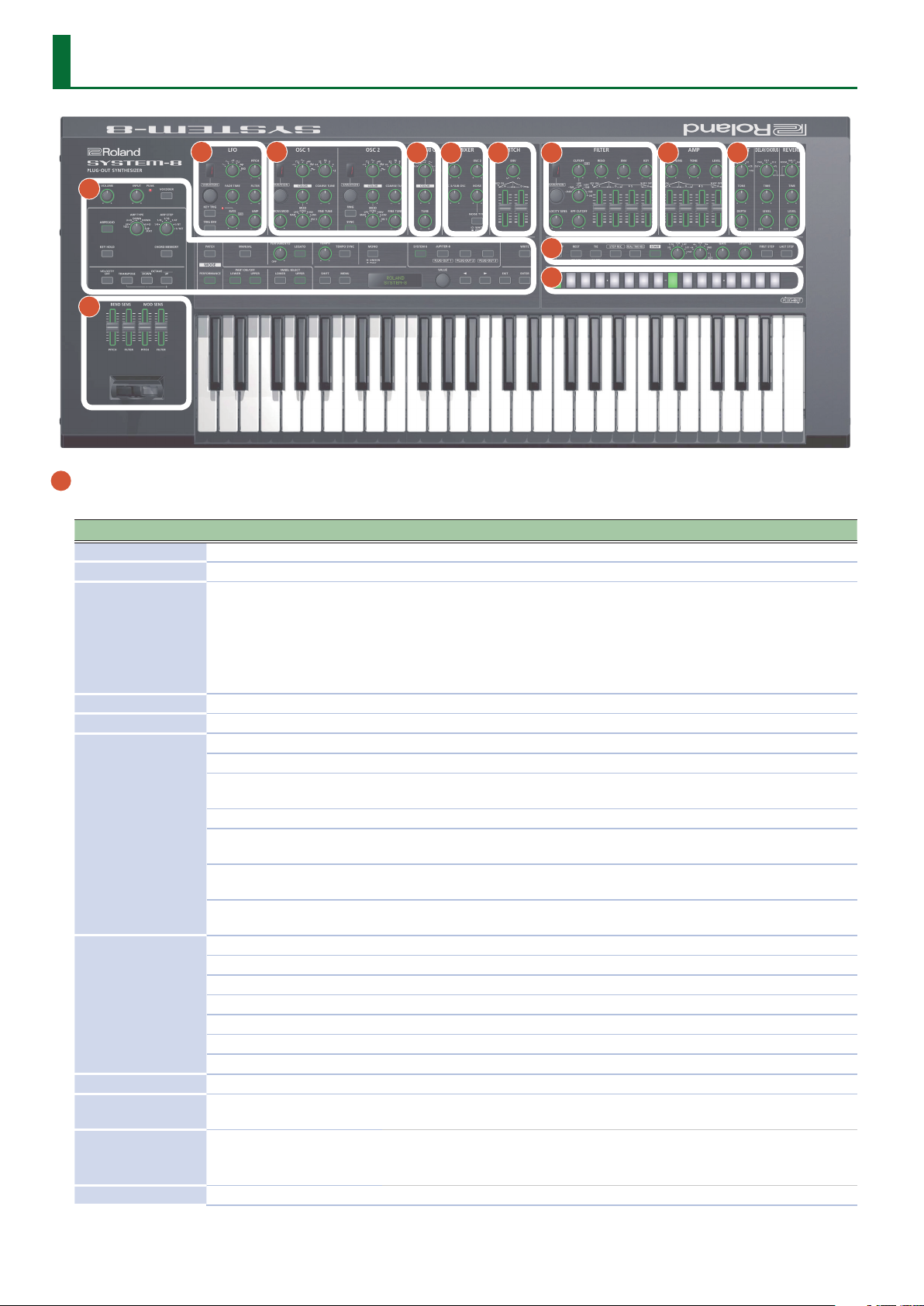
Panel Descriptions
2 3
4 5 6 7 8 9
1
11
12
10
1 Common section
Here you can make the following settings for the SYSTEM-8.
Controller Value Explanation
[VOLUME] knob --- Adjusts the volume.
[INPUT] knob --- Adjusts the volume level of the INPUT R and L/MONO jacks.
Indicates the analog input level of the rear panel INPUT R, L/MONO jacks.
The PEAK indicator lights if the input level is excessive.
PEAK indicator ---
[VOCODER] button ON (lit), OFF (unlit) Switches the vocoder on/o.
[ARPEGGIO] button ON (lit), OFF (unlit) Turns the arpeggio function on/o.
1 OCT UP The keys you press are sounded consecutively upward starting from the lowest.
1 OCT U+D
1 OCT DOWN The keys you press are sounded consecutively downward starting from the highest.
[ARP TYPE] knob
[ARP STEP] knob
[KEY HOLD] button ON (lit), OFF (unlit) Turns the key hold function on/o.
[CHORD MEMORY]
button
[VELOCITY OFF]
button
[TRANSPOSE] button ON (lit), OFF (unlit) Turns the transpose function on/o.
2 OCT DOWN
2 OCT U+D
2 OCT UP
1/4 Quarter note
1/8 Eighth note
1/16 Sixteenth note
1/4T Quarter-note triplet
1/8T Eighth note triplet
1/16T Sixteenth note triplet
ON (lit), OFF (unlit) Turns the chord memory function on/o.
ON (lit), OFF (unlit)
Adjust the volume of your connected equipment so that this indicator lights
occasionally.
* If the PEAK indicator stays lit even after you adjust the connected device, adjust the
system setting INPUT: Gain (p. 21).
Selects the arpeggio type.
The keys you press are sounded consecutively upward starting from the lowest, and
then back down again.
The keys you press, together with the keys one octave above those keys, are sounded
consecutively downward starting from the highest.
The keys you press, together with the keys one octave above those keys, are sounded
consecutively upward starting from the lowest, and then back down again.
The keys you press, together with the keys one octave above those keys, are sounded
consecutively starting with the lowest.
Selects the note value for each step of the arpeggio.
Notes sound at the same volume even if your playing dynamics vary.
The velocity value when “VELOCITY OFF” is on is specied by the system setting
(SYSTEM: KEY TOUCH: Fixed Velo) (p. 18).
2
Page 3
Controller Value Explanation
Octave shift
-3–0–+3 (octave units)
OCTAVE [DOWN]
[UP] buttons
-5–0–+6 (semitone units)
MODE [PATCH]
button
MODE
[PERFORMANCE]
button
PART ON/OFF
[LOWER] [UPPER]
buttons
PANEL SELECT
[LOWER] [UPPER]
buttons
[MANUAL] button ---
[PORTAMENTO]
knob
[LEGATO] button ON (lit), OFF (unlit)
[TEMPO] knob 40.0–300.0 (BPM)
[TEMPO SYNC]
button
[MONO] button MONO, UNISON, POLY
MODEL [SYSTEM-8]
[PLUG-OUT 1]–
[PLUG-OUT 3]
buttons
[WRITE] button --- Saves sounds, step sequencer and system settings.
[SHIFT] button ---
[MENU] button --- Accesses the MENU screen.
Display --- Shows various information for the operation.
[VALUE] knob ---
cursor [K] [J]
buttons
[EXIT] button ---
[ENTER] button --- Press this to conrm a value or execute an operation.
---
---
ON (lit), OFF (unlit) In performance mode, switch the lower part or upper part on/o.
(The button of the selected
part is lit)
OFF, 1–255
ON (lit), OFF (unlit)
(The button of the selected
synthesizer is lit)
---
These buttons let you shift the pitch range of the keyboard in one-octave units. The
button is lit if the pitch is shifted by one octave, and blinking if the pitch is shifted by
two or three octaves.
Key transpose
By pressing a [DOWN] [UP] button while holding down the [TRANSPOSE] button,
you can transpose (shift the pitch of ) the keyboard in semitone units.
Switches to Patch mode.
&
“Editing a Patch” (p. 9)
Switches to Performance mode.
&
“Editing a Performance” (p. 11)
In performance mode, select the part (lower or upper) that is the target of panel
operations.
Causes sound to be produced according to the current settings of the knobs and
sliders.
Adjusts the time over which pitch change occurs when portamento is applied.
Portamento is an eect that smoothly changes the pitch between one key and the
next-played key.
Applies portamento only when you play legato (i.e., when you press the next key
before releasing the previous key).
Species the tempo of the step sequencer and arpeggiator. The indicator blinks at
the specied tempo.
The modulation speed (RATE) of the
9
EFFECTS section are synchronized to the tempo.
If this is on (lit), the synth will play monophonically (single notes).
If this is blinking, the synth will play all sounds in unison (UNISON mode).
When the [SYSTEM-8] button is on, this instrument operates as the SYSTEM-8
synthesizer. When one of the [PLUGOUT 1–3] buttons is on, this instrument operates
as a PLUG-OUT synthesizer.
When used in conjunction with other buttons or knobs, lets you view parameters or
edit dierent parameters.
By holding down the [SHIFT] button and turning the [VALUE] knob to change the
value, you can edit a setting in steps of 10.
Change the value at the cursor position.
By holding down the [SHIFT] button and turning the [VALUE] knob to change the
value, you can edit a setting in steps of 10.
Move the cursor left/right.
Alternatively, switch screens.
Returns you to the previous screen.
In some screens, this cancels the operation currently being executed.
2
LFO section and the delay time (TIME) of the
Panel Descriptions
3
Page 4
Panel Descriptions
2 LFO
Here you can create cyclic change (modulation) in the sound by applying vibrato (pitch modulation) or tremolo (volume modulation).
Controller Value Explanation
Selects the variation of the LFO section.
Variation 1
[VARIATION] knob
(only for MODEL:
SYSTEM-8)
Wave knob
(only for MODEL:
SYSTEM-8)
[PITCH] knob -128–0–+127 Allows the LFO to modulate the pitch of the partial, producing a vibrato eect.
[FADE TIME] knob 0–255
[FILTER] knob -128–0–+127 Allows the LFO to modulate the FILTER CUTOFF (cuto frequency),
[KEY TRIG] button ON (lit), OFF (unlit)
[TRIG ENV] button ON (lit), OFF (unlit) Causes the envelope to start repeatedly at the LFO cycle (on).
[RATE] knob 0–255
[AMP] knob -128–0–+127 Allows the LFO to modulate the AMP LEVEL (volume), producing a tremolo eect.
Variation 2
Variation 3
R
S
T
U
W
RND Random wave (RND) Random wave (RND x 2) TYPE 6
Variation 1 (Single LFO)
A standard LFO.
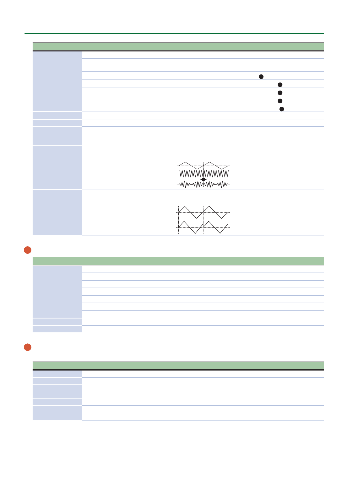
Variation 2 (Dual LFO)
This LFO is created by using a separate second LFO to apply frequency modulation
to the same LFO waveform as Variation 1. The second LFO is a sine wave ve octaves
lower.
Variation 3 (Resonanced Pulse LFO)
This is a pulse waveform with resonance.
The waveform knob selects the frequency of the resonance.
Variation 1 Variation 2 Variation 3
Sine wave (SIN) Sine wave (SIN x 2) TYPE 1
Triangle wave (TRI) Triangle wave (TRI x 2) TYPE 2
Sawtooth wave (SAW) Sawtooth wave (SAW x 2) TYPE 3
Square wave (SQR) Square wave (SQR x 2) TYPE 4
Sample and Hold (S&H) Sample and Hold (S&H x 2) TYPE 5
Species the time from when the tone sounds until the LFO reaches its maximum
amplitude.
Species whether the LFO waveform is synchronized to start the moment you press a
key (on) or is not synchronized (o).
Determines the speed of the LFO modulation.
The indicator blinks at the speed (rate) of the LFO modulation.
This knob is a GRF (GRIFFER) knob which allows high-precision adjustments.
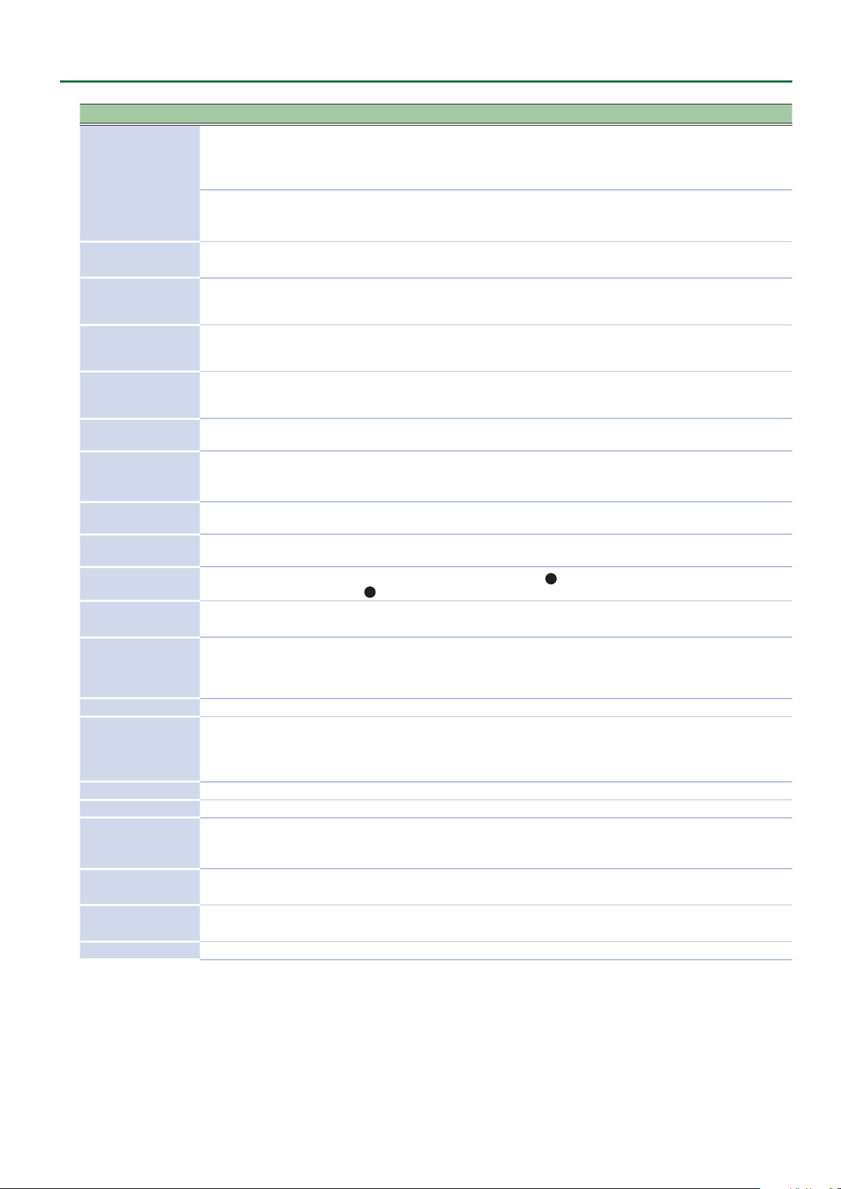
3 OSC 1, OSC 2
Here you can select the waveform that determines the character of the sound, and specify its pitch. The SYSTEM-8 has three oscillators (OSC 1,
OSC 2, and 4 OSC 3/SUB OSC).
Controller Value Explanation
[VARIATION] knob
(only for MODEL:
SYSTEM-8)
Wave knob
(only for MODEL:
SYSTEM-8)
Octave (feet) knob 64, 32, 16, 8, 4, 2 Species the octave of the oscillator.
[COLOR] knob 0–255
Variation 1 This is the basic oscillator waveform.
Variation 2 This is a distinctive oscillator waveform.
T
U
S
T
T
U
U
S
S
Select the variation of the OSC 1 and OSC 2 sections.
Variation 1 Variation 2
Sawtooth wave (SAW) Noise Saw (NOISESAW)
Square wave (SQR) Logic Operation (LOGIC)
Triangle wave (TRI) FM (FM)
Sawtooth wave2 (SAW2) FM+SYNC (FM SYNC)
Square wave2 (SQR2) Vowel (VOWEL)
Triangle wave2 (TRI2) CB (COWBELL)
Adjusts the tone.
The result depends on the waveform.
4
Page 5
Controller Value Explanation
Selects the source that is modulated by the [COLOR] knob.
The sound is determined by the position of the [COLOR] knob. It will not vary over
time.
The sound varies over time at the rate specied in the
The sound changes over time according to the envelope of the
The sound changes over time according to the envelope of the
The sound changes over time according to the envelope of the
The sound changes over time according to the frequency of the
[MOD] knob
MAN
LFO
P. ENV
F. ENV
A. ENV
OSC 3
[COARSE TUNE] knob -11–0–+11 Adjusts the pitch in semitone steps.
[FINE TUNE] knob -128–0–+127 Allows ne pitch adjustments.
[CROSS MOD] knob
(OSC 1 only)
0–255
Modies the OSC 1 frequency according to the OSC 2 waveform. Turning the knob
toward the right makes OSC 1 become a more complex sound, allowing you to create
metallic sounds or sound eects.
This is a ring modulator. It generates a complex waveform by multiplying OSC 1 and
OSC 2.
[RING] button
(OSC 2 only)
ON (lit), OFF (unlit)
OSC 1
OSC 2
This is oscillator sync. It generates a complex waveform by forcibly resetting OSC 2 to
the beginning of its cycle in synchronization with the OSC 1 frequency.
2
LFO section.
Panel Descriptions
6
PITCH section.
7
FILTER section.
8
AMP section.
4
OSC 3.
[SYNC] button
(OSC 2 only)
ON (lit), OFF (unlit)
OSC 1
OSC 2
4 OSC 3/SUB OSC
Controller Value Explanation
Selects the waveform that is the basis of the sound.
Wave knob
R
R
R
S
S
S
-2Oct
-1Oct
-1Oct
-2Oct
Sine wave two octaves lower
Sine wave one octave lower
Sine wave
Triangle wave
Triangle wave one octave lower
Triangle wave two octaves lower
[COLOR] knob 0–255 The result depends on the waveform.
[TUNE] knob -1200cent–+1200cent Adjusts the pitch of the oscillator.
5 MIXER
Adjust the OSC 1, OSC 2, OSC 3/SUB OSC, Noise’s volume.
Controller Value Explanation
[OSC 1] knob 0–255 Adjust the OSC 1’s volume.
[OSC 2] knob 0–255 Adjust the OSC 2’s volume.
[OSC 3/SUB OSC]
knob
[NOISE] knob 0–255 Adjust the noise’s volume.
[NOISE TYPE] button
0–255 Adjust the OSC 3/SUB OSC’s volume.
White noise (lit),
Pink noise (unlit)
Selects the type of the noise.
5
Page 6
Panel Descriptions
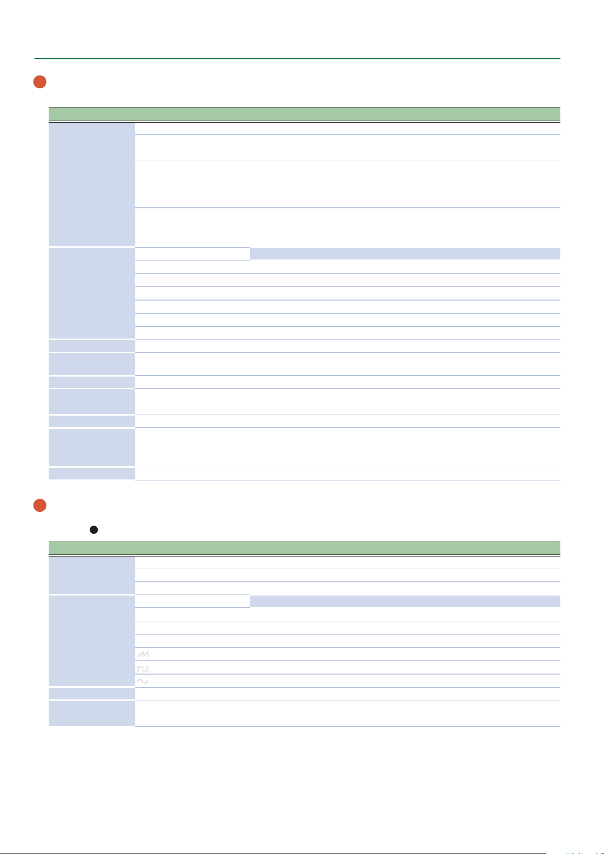
6 PITCH
Here you can create time-varying change (envelope) for pitch.
Controller Value Explanation
If this knob is turned toward the right, the pitch initially becomes higher and then
[ENV] knob -128–0–+127
[A] slider
[D] slider
0–255
7 FILTER
These settings determine the brightness and thickness of the sound. Here you can also specify the time-varying change (envelope) for the lter.
Controller Value Explanation
[VARIATION] knob
(only for MODEL:
SYSTEM-8)
[CUTOFF] knob 0–255
Filter type knob
(only for MODEL:
SYSTEM-8)
[RESO] knob 0–255
[ENV] knob -128–0–+127
[KEY] knob -128–0–+127
[VELOCITY SENS]
knob
[HPF CUTOFF] knob 0–255
[A] slider
[D] slider
[S] slider
[R] slider
LPF/HPF (Variation 1) Low pass lter (LPF), High pass lter (HPF)
SBF (Variation 2) Side band lter (SBF)
(Variation 1)
LPF-24dB, LPF-18dB,
LPF-12dB, HPF-12dB,
HPF-18dB, HPF-24dB
(Variation 2)
SBF1–SBF6
0–255
0–255
returns to the pitch of the key you pressed.
If this knob is turned toward the left, the pitch initially becomes lower and then
returns to the pitch of the key you pressed.
8
These sliders operate similarly to the [A] [D] sliders of the
AMP section (they aect
the pitch rather than the volume).
Selects the variation of the FILTER section.
Species the cuto frequency of the lter.
This knob is a GRF (GRIFFER) knob which allows high-precision adjustments.
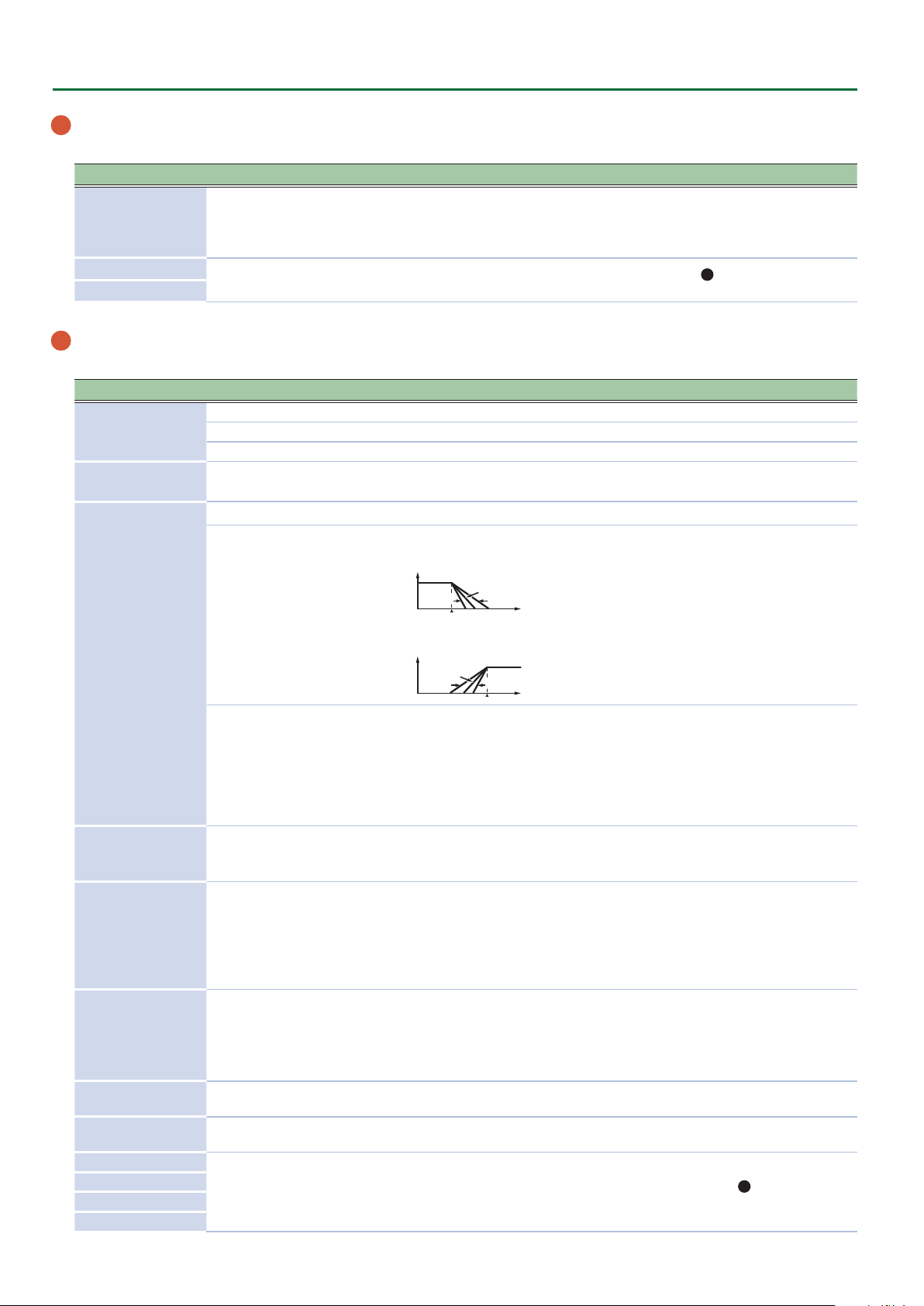
Selects the slope of the lter.
Low pass lter (LPF), High pass lter (HPF)
LPF: -24dB, -18dB, -12dB
Volume
-24 dB
-18 dB
-12 dB
Frequency
HPF: -12dB, -18dB, -24dB
Volume
-18 dB
-12 dB
-24 dB
Frequency
Side band lter (SBF)
You can use the [CUTOFF] knob to adjust the band interval.
You can also use the lter type knob to select the range of the band interval.
SBF1–3: Low range, Mid range, High range with original sound
SBF4–6: High range, Mid range, Low range without original sound
You can use the resonance knob to adjust the band width.
Resonance boosts the sound in the region of the lter’s cuto frequency.
Higher settings produce stronger emphasis, creating a distinctively “synthesizer-
like” sound.
This knob species the depth and direction of the cuto frequency change produced
by the [A], [D], [S], and [R] sliders.
If the knob is turned toward the right, the cuto frequency moves in the upward
direction.
If the knob is turned toward the left, the cuto frequency moves in the downward
direction.
Allows the lter cuto frequency to vary according to the key that you play.
If the knob is turned toward the right, the cuto frequency becomes higher as you
play higher notes.
If the knob is turned toward the left, the cuto frequency becomes lower as you play
lower notes.
Adjusts the sensitivity by which the key velocity (playing dynamics) varies the depth
of the lter envelope.
Species the cuto frequency of the high-pass lter. Frequency components below
the cuto frequency are cut.
These sliders operate similarly to the [A] [D] [S] [R] sliders of the
8
AMP section
(they aect the cuto frequency rather than the volume).
6
Page 7
8 AMP
Here you can create time-varying change (envelope) for the volume.
Controller Value Explanation
[VELOCITY SENS]
knob
0–255
Adjusts the sensitivity by which the key velocity (playing dynamics) varies the
volume.
[TONE] knob -128–0–+127 Adjusts the brightness of the sound.
[LEVEL] knob 0–255 Adjusts the volume.
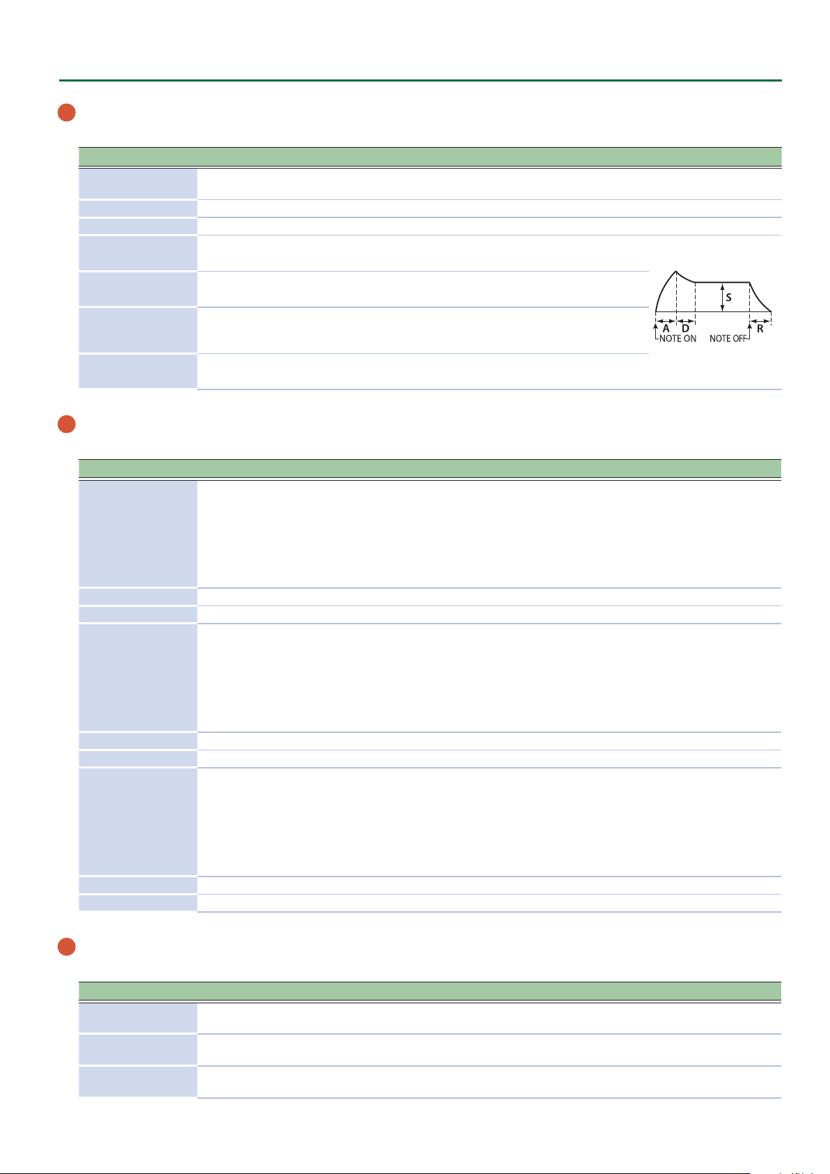
[A] slider
(Attack time)
[D] slider
(Decay time)
[S] slider
(Sustain level)
[R] slider
(Release time)
0–255
0–255
0–255
0–255
Species the time from the moment you press the key
until the maximum volume is reached.
Species the time from when the maximum volume is
reached, until it decays to the sustain level.
Species the volume level that will be maintained from
when the attack and decay times have elapsed until you
release the key.
Species the time from when you release the key until the
volume reaches its minimum value.
9 EFFECTS, DELAY/CHORUS, REVERB
Here you can adjust the eect, delay/chorus, and reverb depth.
Controller Value Explanation
OD
(OVERDRIVE),
DS
(DISTORTION),
MT
Eect type knob
FZ
(FUZZ),
CR
(CRUSHER),
PH
(PHASER)
(METAL),
[TONE] knob 0–255 Species the character of the eect.
[DEPTH] knob OFF, 1–255 Species the depth of the eect.
(DELAY),
DLY
PAN
(PANNING DELAY),
CH1
Delay/chorus type
knob
(CHORUS 1),
CH2
(CHORUS 2),
FL
(FLANGER),
DLY+CH
(DELAY + CHORUS)
[TIME] knob 0–255 Adjusts the time by which the sound is delayed.
[LEVEL] knob OFF, 1–255 Adjusts the volume of delay/chorus.
(AMBIENCE),
AMBI
ROOM
(ROOM),
HALL1
Reverb type knob
HALL2
PLATE
MOD
(HALL 1),
(HALL 2),
(PLATE),
(MODULATION)
[TIME] knob 0–255 Species the reverb time.
[LEVEL] knob OFF, 1–255 Species the reverb volume.
Selects the eect type.
Switches the delay/chorus type.
Switches the reverb type.
Panel Descriptions
10 PITCH BEND/MODULATION
This allows you to control pitch bend or apply vibrato.
Controller Value Explanation
BEND SENS [PITCH]
slider
BEND SENS [FILTER]
slider
MOD SENS [PITCH]
slider
0–255 Species the amount of the pitch change produced by pitch bend operations.
0–255 Species the amount of the lter change produced by pitch bend operations.
0–255 Species the amount of the pitch change produced by modulation operations.
7
Page 8
Panel Descriptions
Controller Value Explanation
MOD SENS [FILTER]
slider
Pitch bend/
Modulation lever
11 Step sequencer
Here you can record your keyboard performance and knob operations, and play them back repeatedly.
Controller Value Explanation
[EDIT/DISP] button --- Shows the STEP SEQ screen.
[REST] button ---
[TIE] button ---
[STEP REC] button --- Starts step recording.
[REAL TIME REC]
button
[START] button --- Plays the step sequencer.
[SCALE] knob
[PLAY MODE] knob
[GATE] knob -128–0–+127 You can adjust the duration of the note recorded at each step.
[SHUFFLE] knob -128–0–+127
[FIRST STEP] button
[LAST STEP] button
0–255 Species the amount of the lter change produced by modulation operations.
While playing the keyboard, move the lever toward the left to lower the pitch, or
---
toward the right to raise the pitch.
Move the lever away from yourself to apply vibrato.
Enters a rest during STEP REC.
If you hold down the [EDIT/DISP] button and press the [REST] button, the SEQ
ERASE screen appears.
Enters a tie during STEP REC.
If you hold down the [EDIT/DISP] button and press the [TIE] button, the STEP
LENGTH screen appears.
--- Starts realtime recording.
1/8 Eighth note
1/16 Sixteenth note
1/32 Thirty-second note
1/4T Quarter-note triplet
1/8T Eighth-note triplet
1/16T Sixteenth-note triplet
(FWD)
(REV)
(FWD&REV)
(INVERT)
RND
(RND) Play steps randomly.
KEY TRIG
(TRIG) Play normally while the keyboard is held.
Play forward from the rst step.
Play backward from the last step.
Play forward from the rst step, and then play backward from the last step.
Play with even-numbered and odd-numbered steps inverted.
You can adjust the timing of the notes for even-numbered steps (Step 2, Step 4, Step
6...).
If the knob is in the center position, the timing is not adjusted.
1– (the value specied for
STEP LENGTH)
1– (the value specied for
STEP LENGTH)
Plays with the specied step as the rst step.
Plays with the specied step as the last step.
&
For details on the step sequencer, refer to “Step Sequencer” (Owner’s Manual
12 [A]–[H], [1]–[8] buttons
Use these buttons to recall sounds.
A–H (bank), 1–8 (number)
These buttons also indicate steps of the step sequencer.
1–16 (step)
8
p.14
).
Page 9

Editing a Patch
Patch mode
This is the SYSTEM-8’s basic mode, in which it plays a single part.
* Use the MODEL buttons to select the desired synthesizer sound engine.
1. Press the MODE [PATCH] button.
The SYSTEM-8 is in patch mode.
2. Select a patch as necessary.
3. Move the top panel knobs and sliders.
When you operate a knob or slider, the parameter name, and value appear. After a few seconds, the top screen reappears.
OSC1:
Wave SAW
When you edit a patch, an “*” appears at the left of the Bank–Number.
PATCH SYS8 *A-1
SY System-8 Saws
Editing a Patch’s Bender Settings or Patch Name (PATCH EDIT)
MEMO
For the SYSTEM-8, all settings other than Bend Range and Gain can be controlled from the panel controllers.
1. In patch mode, press the [MENU] button.
2. Use the cursor [
3. Use the cursor [
4. Press the [EXIT] button to return to the MENU screen.
Patch parameters
Menu
[SHIFT] + cursor [K] [J]
BEND
NAME (Patch Name) Species the name of the patch.
* For the JUPITER-8 (PLUG-OUT 1), Bend Range, Gain, and parameters not assigned to the panel can be edited in PATCH EDIT.
K
] [J] buttons to select “PATCH EDIT,” and then press the [ENTER] button.
K
] [J] buttons to select a parameter, and use the [VALUE] knob to edit the value.
Parameter
Cursor [K] [J]
Bend Range 1–24
Bend Gain x1, x2, x3, x4
Value
[VALUE] knob
Explanation
Species the amount of pitch change (in semitone units, up to two
octaves) that occurs when you operate the pitch bend lever.
Species a multiplier for the Bend Range, extending the range of change.
For example, if the Bend Range is set to “24” and the Bend Gain is “x4,”
the range of pitch bend change will be eight octaves.
Simulating Aging (CONDITION)
The SYSTEM-8 can simulate the changes that occur in an older unit (Aging).
The condition setting is saved as a patch parameter.
1. In patch mode, press the [MENU] button.
2. Use the cursor [
3. Use the [VALUE] knob to edit the value.
4. Press the [EXIT] button to return to the MENU screen.
Parameter Value
CONDITION -128–0–+127 (Default: 0)
K
] [J] buttons to select “CONDITION,” and then press the [ENTER] button.
9
Page 10
Editing a Patch
Initializing a Patch (Patch Init)
Here’s how to initialize the patch in the temporary area, setting it to
“Init Patch” (the basic sound).
1. Hold down the [SHIFT] button, and then press the
MODE [PATCH] button.
A conrmation message appears.
Patch Init?
[Exit]:N [Ent]:Y
2. To initialize, press the [ENTER] button.
If you decide to cancel, press the [EXIT] button.
MEMO
5 When you initialize the patch, an “*” appears beside the
Bank–Number.
PATCH SYS8 *A-1
----------------
5 When you initialize the patch in performance mode, the
patch of the part selected by PANEL SELECT is initialized.
6. Press the [ENTER] button.
A conrmation message appears.
Patch Write?
[Exit]:N [Ent]:Y
7. To save, press the [ENTER] button.
If you decide to cancel, press the [EXIT] button.
When saving is completed, the display indicates “Completed!”
Completed!
MEMO
Arpeggio, chord memory, and step sequencer settings/data
are also saved within the patch data.
Saving a Patch (WRITE)
1. In patch mode, press the [WRITE] button.
The WRITE screen appears.
<WRITE> [Ent]
PATCH* À
When you edit a patch, the display indicates “PATCH*.”
2. Press the [ENTER] button.
The PATCH NAME screen appears.
PATCH NAME [Ent]
User_Patch_Name
3. Use the cursor [
to change the character.
Operation Explanation
[SHIFT] button
+ cursor [K] button
[SHIFT] button
+cursor [J] button
[SHIFT] button
+ [VALUE] knob
K
] [J] buttons and the [VALUE] knob
Deletes one character (Erase).
Inserts one character (Insert).
Switches between uppercase/
lowercase/numerals.
4. Press the [ENTER] button.
A screen allows you to select the save-destination.
To:SYS8 A-1[Ent]
[SY System- aws]
5. Use the [VALUE] knob to select the save-destination.
10
Page 11
Editing a Performance
Performance mode
In this mode you can assign a patch to each of two parts (UPPER part and LOWER part) and play them in dual or single performance modes.
In patch mode, the tempo and AUDIO INPUT (Vocoder) settings are only system settings; however in performance mode, each performance
can have its own values for these settings.
1. Press the MODE [PERFORMANCE] button.
The SYSTEM-8 is in performance mode.
2. Select a performance as necessary.
Editing a patch
Use the PANEL SELECT [UPPER] [LOWER] buttons to select the part (UPPER part, LOWER part) that you want to edit.
Detailed editing is the same as in patch mode.
Editing a performance
There are two screens: the PERFORM EDIT screen (where you edit settings for the overall performance) and the PART EDIT screen (settings for
each part).
3. Press the [MENU] button.
The MENU screen appears.
Making Settings for the Entire Performance (PERFORM EDIT)
4. Use the cursor [
K
] [J] buttons to select “PERFORM EDIT,” and then press the [ENTER] button.
<MENU> [Ent]
ÄPERFORM EDIT À
* “PERFORM EDIT” is not shown in patch mode.
5. Use the cursor [
PERFORM:COMMON
Perf Mode DUAL
Parameter
K
] [J] buttons to select a parameter, and use the [VALUE] knob to edit the value.
Menu
Value
6. Press the [EXIT] button to return to the MENU screen.
Performance parameters
Menu
[SHIFT] +cursor [K] [J]
COMMON
Parameter
Cursor [K] [J]
Perf Mode
Perf Level -INF, -53.0dB–0.0dB–10.0dB Species the volume of the performance.
Value
[VALUE] knob
DUAL
SINGLE
Explanation
In this mode you can perform using both the upper part and
the lower part. Each part has a maximum polyphony of four
notes.
You can use the Key Range setting to freely create splits or
partial layers.
In this mode you can perform using either the upper part or
the lower part. The part you play has a maximum polyphony
of eight notes.
In this mode, use the PANEL ON/OFF [UPPER] [LOWER]
buttons to select the part that you want to play.
While being in performance mode, this setting lets you play
just as in patch mode. The Arp Src and Arp Dst settings you
specied for the performance are ignored, and the settings
stored in the patch are used.
11
Page 12

Editing a Performance
Menu
[SHIFT] +cursor [K] [J]
COMMON
ARPEGGIO
CV/GATE OUT
INPUT
Parameter
Cursor [K] [J]
Value
[VALUE] knob
PartBalance LW64–0–UP63
Tempo Src KNOB, PERF
Perf Tempo
* Valid when Tempo
40.0–300.0 (BPM)
Src=PERFORM
Arp Src LOWER, UPPER
LOWER,
Arp Dst
UPPER,
UP&LW
Prm Src SYSTEM, PERFORM
Ref Note C0, C1, C2, C3, C4
ALL
KBD (L) Keyboard performance data of the lower part is output.
KBD (U) Keyboard performance data of the upper part is output.
KBD (U&L) Keyboard performance data is output.
STEP SEQ (L)
Src
* Valid when Prm
Src=PERFORM
STEP SEQ (U)
PATCH (L) The behavior of the lower part's sound engine is output.
PATCH (U) The behavior of the upper part's sound engine is output.
USB OMNI
USB CH1–USB CH16 The note data of a specied USB MIDI channel is output.
MIDI IN OMNI
MIDI IN CH1–MIDI IN CH16 The note data of a specied MIDI IN channel is output.
Bend Range
* Valid when Prm
1–24
Src=PERFORM
Portamento
* Valid when Prm
Src=PERFORM
OFF Portamento is not applied.
ALWAYS Portamento is always applied.
LEGATO
Porta Time
* Valid when Prm
0–127
Src=PERFORM
Prm Src SYSTEM, PERFORM
(DELAY),
DLY
PAN
Delay Type
* Valid when Prm
Src=PERFORM
(PANNING DELAY),
CH1
(CHORUS 1),
CH2
(CHORUS 2),
FL
(FLANGER),
DLY+CH
(DELAY + CHORUS)
Delay Time
* Valid when Prm
0–255 Adjusts the time by which the sound is delayed.
Src=PERFORM
Explanation
LW64: LOWER only (UPPER does not sound)
0: LOWER and UPPER have the same volume
UP63: UPPER only (LOWER does not sound)
Selects whether the tempo setting follows the value of the
knob (KNOB) or the setting of the program (PROGRAM).
Species the tempo when the Tempo Src setting is “PERF.”
* If you hold down the [SHIFT] button and turn the [VALUE]
knob, the value changes in 0.1 steps.
Selects the part that uses the arpeggio settings.
CHORD MEMORY also operates according to this setting.
Selects the part to which the arpeggio applies.
If you choose UP&LW, the arpeggio applies to both the upper
part and lower part.
CHORD MEMORY also operates according to this setting.
Selects whether the CV/GATE OUT setting follows the
system setting (SYSTEM) or the setting of the performance
(PERFORM).
In steps of an octave, species the note number for which CV
OUT is 0 V.
Keyboard (both upper and lower), step sequencer (both
upper and lower), USB (OMNI), and MIDI IN (OMINI) data are
output.
Step sequencer performance data of the lower part is
output.
Step sequencer performance data of the upper part is
output.
The note data of all USB MIDI channels is combined and
output.
The note data of all MIDI IN channels is combined and
output.
Species the amount (in semitone units, up to two octaves)
of pitch change that occurs when you move the pitch bend
lever.
Portamento is applied when you hold down a key and press
another key.
When portamento is used, this species the time over which
the pitch will change.
Select whether the INPUT setting follows the system setting
(SYSTEM) or the setting of the performance (PERFORM).
Switches the delay/chorus type.
12
Page 13

Editing a Performance
Menu
[SHIFT] +cursor [K] [J]
INPUT
INPUT (Voc)
* Parameters for
vocoder-related
settings.
NAME (Performance Name) Species the name of the performance.
Parameter
Cursor [K] [J]
Delay Level
* Valid when Prm
Src=PERFORM
ReverbType
* Valid when Prm
Src=PERFORM
Reverb Time
* Valid when Prm
Src=PERFORM
Reverb Level
* Valid when Prm
Src=PERFORM
Formant
* Valid when Prm
Src=PERFORM
Consonant
* Valid when Prm
Src=PERFORM
Balance
* Valid when Prm
Src=PERFORM
Carrier
Value
[VALUE] knob
OFF, 1–255 Adjusts the volume of delay/chorus.
(AMBIENCE),
AMBI
ROOM
(ROOM),
HALL1
(HALL 1),
HALL2
(HALL 2),
PLATE
(PLATE),
MOD
(MODULATION)
0–255 Adjusts the length of the reverb sound’s decay.
OFF, 1–255 Adjusts the volume of the reverb sound.
0–255 Species the formant (vocal character).
-40dB–0dB–+40dB Species the volume of the consonants.
D128–0–W127
LOWER Lower part
UPPER Upper part
UP&LW Both the upper part and lower part
Explanation
Switches the reverb type.
D128: Mic input (direct sound) only
0: Mic input and vocoder sound are at the same
volume
W127: Vocoder sound only
Species the source of the carrier.
Making Settings for Each Part (PART EDIT)
7. Use the Cursor [
<MENU> [Ent]
ÄPART EDIT À
* “PART EDIT” is not shown in patch mode.
8. Use the cursor [
Sound selection screens for the upper part and lower part
UPPER mmmm b-n
User_Patch_Name
LOWER mmmm b-n
User_Patch_Name
MEMO
Use the PANEL SELECT [LOWER] [UPPER] buttons to select the part whose sound you want to edit.
K
] [J] buttons to select “PART EDIT,” and then press the [ENTER] button.
K
] [J] buttons to select a parameter, and use the [VALUE] knob to edit the value.
mmmm: Model button
b-n: Bank–Number
Patch name
Examples of other editing screens
PART:COMMON [U]
Level 0.0dB
PART:PITCH [L]
Octave -1
13
Page 14

Editing a Performance
PART:COMMON [U]
Level 0.0dB
Upper: [U]
Lower: [L]
PART:COMMON [L]
Level 0.0dB
Part parameters
Use the PANEL SELECT [LOWER] [UPPER] buttons to select the part whose sound you want to edit.
Menu
[SHIFT] + cursor [K] [J]
(select sound) (Patch name)
COMMON
PITCH
CTRL
Parameter
Cursor [K] [J]
LEVEL -INF, -53.0dB–0.0dB–10.0dB
Pan L5–CENTER–R5
Range Lower C–G9
Range Upper C–G9
Octave -3–0–+3 Species the octave of the part.
Transpose -12–0–+12 Adjusts the pitch of the part in semitone units.
Fine Tune -100–0–+100 Adjusts the ne tuning of the part.
Rx Bend OFF, ON
Rx Mod OFF, ON
Rx Hold OFF, ON
Rx Express OFF, ON
Value
[VALUE] knob
Explanation
Species the volume of each part.
This is used mainly to adjust the volume balance between
parts.
Species the stereo position of each part. “L5” is far left,
“CENTER” is center, and “R5” is far right.
For each part, species the lowest key of the keyboard range
that is sounded.
For each part, species the highest key of the keyboard
range that is sounded.
* If you attempt to raise the lowest key above the highest
key, or lower the highest key below the lowest key, the
other setting changes to the same value.
For each part, species whether MIDI pitch bend messages
are received (ON) or are not received (OFF).
For each part, species whether MIDI modulation messages
are received (ON) or are not received (OFF).
For each part, species whether MIDI hold messages are
received (ON) or are not received (OFF).
For each part, species whether MIDI expression messages
are received (ON) or are not received (OFF).
9. Press the [EXIT] button several times to return to the top screen.
MEMO
You can use the PART EDIT: COMMON: Range Lower/Upper parameters to specify the key range (lower and upper) of the upper and lower
parts.
Selecting a patch for each part
5 Normally, you’ll select the patch in the rst item of the PART EDIT screen.
5 While the PART EDIT screen is shown, you can use the [A]–[H] and [1]–[8] buttons to switch patches (the patch name is now shown in the
screen).
5 While the top screen of performance mode is shown, you can select patches as follows.
1. Long-press the PART SELECT [UPPER] or [LOWER] button for which you want to select a patch (don’t release the
button yet).
The patch select screen for the selected part appears, and the sound button turns green.
2. Continuing to long-press the PART SELECT button, select a patch in the same way as when normally selecting a
patch.
You can use the MODEL buttons, [VALUE] knob, [A]–[H], and [1]–[8] buttons.
14
Page 15

Editing a Performance
Initializing a Performance (Perform Init)
Here’s how to initialize the “Perform Edit” and “Part Edit” settings
of the temporary area.
The selected patch is not initialized.
1. Hold down the [SHIFT] button and press the MODE
[PERFORMANCE] button.
A conrmation message appears.
Perform Init?
[Exit]:N [Ent]:Y
2. To initialize, press the [ENTER] button.
If you decide to cancel, press the [EXIT] button.
MEMO
When you initialize the performance, an “*” is shown beside
the Bank–Number.
PERFORM *A-1
----------------
Saving a Performance (WRITE)
1. In performance mode, press the [WRITE] button.
The WRITE screen appears.
<WRITE> [Ent]
PERFORMANCE* À
The PERF NAME screen or PATCH NAME screen appears.
In the case of the PATCH NAME screen
PATCH NAME:[Ent]
User_Patch_Name
In the case of the PERF NAME screen
PERF NAME: [Ent]
User_Perf_Name
4. Use the cursor [
K
] [J] buttons and the [VALUE] knob
to edit the characters.
Oparation Explanation
[SHIFT] button
+ cursor [K] button
[SHIFT] button
+ cursor [J] button
[SHIFT] button
+ [VALUE] knob
Deletes one character (Erase).
Inserts one character (Insert).
Switches between uppercase/
lowercase/numerals.
5. Press the [ENTER] button.
A screen allows you to select the save-destination.
In the case of the PATCH WRITE screen
To:SYS8 A-1[Ent]
[SY System- aws]
2. Use the cursor [
K
] [J] buttons to select what you
want to save.
Selecting a performance
<WRITE> [Ent]
PERFORMANCE* À
Selecting the patch of the upper part
<WRITE> [Ent]
ÄPATCH:Upper* À
Selecting the patch of the lower part
<WRITE> [Ent]
ÄPATCH:Lower* À
NOTE
If you’ve edited a patch (upper, lower) in performance mode
(an “*” is displayed), you must rst save the patch before
saving the performance in order to reproduce the sound of
the performance.
If you rst save the performance, or if you don’t save the
edited patch, the sound of the performance will not be
reproduced.
In the case of the PERF WRITE screen
To:A-1 [Ent]
[Fat Split ]
6. Use the [VALUE] knob to select the save-destination.
7. Press the [ENTER] button.
A conrmation message appears.
In the case of the PATCH WRITE screen
Patch Write?
[Exit]:N [Ent]:Y
In the case of the PERF WRITE screen
Perform Write?
[Exit]:N [Ent]:Y
3. Press the [ENTER] button.
15
Page 16

Editing a Performance
8. To save, press the [ENTER] button.
If you decide to cancel, press the [EXIT] button.
When saving is nished, the screen indicates “Completed!”
Completed!
9. Repeat steps 1–8 to save the necessary edited data,
in the order of rst the patch(es) (upper, lower) and
then the performance.
16
Page 17

Accessing the MENU Screens
1. Press the [MENU] button.
The MENU screen appears.
2. Use the cursor [
The corresponding edit screen appears.
* To edit “MASTER TUNE” or “CONDITION,” use the [VALUE] knob to edit the value without pressing the [ENTER] button, and then proceed
to step 4.
3. Use the cursor [
K
] [J] buttons to select the item that you want to edit, and press the [ENTER] button.
K
] [J] buttons to select the parameter that you want to edit, and then use the [VALUE] knob to
edit the setting of that parameter.
4. When you have nished editing, press the [EXIT] button several times to return to the top screen.
Menu
Cursor [K] [J]
MASTER TUNE 430.0–440.0–450.0Hz
CONDITION -128–0–+127
SYSTEM ---
PERFORM EDIT ---
PART EDIT ---
PATCH EDIT ---
STEP SEQ MENU ---
UTILITY ---
VERSION INFO ---
PLUG-OUT INFO ---
Value
[VALUE] knob
Explanation
Specify the basic pitch of the SYSTEM-8.
This is saved within the system settings.
Species the state (condition) of the analog sound engine circuit that is being
modeled.
This is saved within the patch data.
Make settings of the entire SYSTEM-8 (only in performance mode).
&
“Making System Settings (SYSTEM Setting Screen)” (p. 18)
Access the performance edit screen (only in performance mode).
&
“Making Settings for the Entire Performance (PERFORM EDIT)” (p. 11)
Access the part edit screen.
&
“Making Settings for Each Part (PART EDIT)” (p. 13)
Access the patch edit screen.
&
“Editing a Patch” (p. 9)
Make settings for the step sequencer.
&
“STEP SEQ MENU” (p. 33)
Access various utility functions.
&
“Convenient Functions (UTILITY)” (p. 23)
View the SYSTEM-8’s system program version.
&
“Viewing the System Version (VERSION INFO)” (p. 22)
Shows the version of the PLUG-OUT.
&
“Viewing Plug-Out Information (PLUG-OUT INFO)” (p. 22)
Finely adjusting the tempo
1. Hold down the [SHIFT] button and press the [MENU] button.
The TEMPO Adjust screen appears.
TEMPO Adjust:
120.0
2. Use the [VALUE] knob to adjust the tempo.
3. By holding down the [SHIFT] button and turning the [VALUE] knob, you can adjust the value below the
decimal point.
4. Press the [EXIT] button to exit the screen.
17
Page 18

Making System Settings (SYSTEM Setting Screen)
Here’s how to make overall settings for the SYSTEM-8 itself.
1. Press the [MENU] button.
2. Use the Cursor [
The SYSTEM screen appears.
K
] [J] buttons to select “SYSTEM,” and then press the [ENTER] button.
GENERAL:
LCD Contrast 5
3. Hold down the [SHIFT] button and use the cursor [
4. Use the cursor [
K
] [J] buttons to select the parameter that you want to edit, and then use the [Value] knob to
K
] [J] buttons to select the menu item that you want to edit.
edit the setting of that parameter.
5. Press the [EXIT] button several times to return to the top screen.
System parameter list
Menu
[SHIFT] +cursor [K] [J]
GENERAL
KEY TOUCH
Parameter
Cursor [K] [J]
LCD Contrast 1–10 Adjusts the contrast of the display.
Knob LED OFF, ON
LED Bright 1–10 Species the brightness of the knob and slider LEDs.
Auto O OFF, 30min, 240min
Startup PATCH, PERFORM Species the mode at start-up.
StartupPAT
* Appears if Startup
is set to PATCH
StartupPRF
* Appears if Startup
is set to PERFORM
Knob Mode DIRECT, CATCH
LED Demo OFF, 1min–10min Species the time (minutes) until the LED demo is shown.
Fixed Velo 1–127
Velo Crv
Velo Oset -10–0–+10
Value
[VALUE] knob
MANUAL, SYS8 A1–SYS8
H8, PLG1 A1–H8
A-1–H-8 Species the performance number that is selected at startup.
LIGHT
MEDIUM This is the standard keyboard touch setting.
HEAVY
Explanation
Species whether the knob and slider LEDs are lit (ON) or unlit
(OFF).
If this setting is “ON,” the LED is lit when the setting can be edited
by the knob or slider. The LED of a knob or slider whose operation
has no eect is unlit.
Species whether the unit will turn o automatically after a certain
time has elapsed.
If you don’t want the unit to turn o automatically, choose “OFF”
setting.
Species the patch number that is selected at startup.
When you operate a knob, this setting species whether control
data corresponding to the knob’s position is always transmitted
(DIRECT) or whether control data is transmitted only after the
knob passes through the current value of the parameter (CATCH).
The transmitted velocity value will be xed, regardless of the force
with which you strike the key.
The keyboard will have a lighter-feeling touch.
Since you’ll be able to reach fortissimo ( ) without having to play
as strongly as with the “MEDIUM” setting, the keyboard will feel
lighter. This setting makes it easier for people with reduced nger
strength to play the keyboard.
The key will have a heavier-feeling touch.
Since you’ll need to play more strongly than with the “MEDIUM”
setting in order to reach fortissimo ( ), the keyboard will feel
heavier. This setting allows you to use your playing dynamics to
add more expression to your performances.
Adjusts the keyboard velocity curve.
Lower values make the keyboard feel lighter.
Higher values make the keyboard feel heavier.
18
Page 19

Making System Settings (SYSTEM Setting Screen)
Menu
[SHIFT] +cursor [K] [J]
PEDAL
SOUND
SYNC
MIDI
Parameter
Cursor [K] [J]
HoldPolarity STD, RVS
Value
[VALUE] knob
Explanation
Selects the polarity of the pedals.
Depending on the model of pedal, the result of depressing or
releasing the pedal might be the opposite of what you expect. If
Exp Polarity STD, RVS
so, choose the “RVS” setting. If you’re using a Roland pedal (that
has no polarity switch), choose the “STD” setting.
Enables/disables the connection between the controller section
OFF
ON
Local Sw
(keyboard, pitch bend/modulation lever, wheels, panel knobs and
buttons, pedals, etc.) and the internal sound engine.
Normally you should leave this “ON.”
Choose "SURFACE" if you want to use operations on the SYSTEM-8
SURFACE
to only control an external sound module. The sound engine of
the SYSTEM-8 does not produce sound.
Boost Mode OFF, ON Turning this ON boosts the output level of the OUTPUT jacks.
OutputGain -12dB–0dB–+12dB Adjusts the SYSTEM-8’s overall output gain.
Species the tempo source.
If this is set to AUTO, the tempo automatically synchronizes to
TempoSync AUTO, MIDI, USB, INT
MIDI clock if MIDI clock is input via the MIDI IN connector or the
USB port.
If this is set to INT, the tempo specied on the SYSTEM-8 itself is
used.
Species whether step sequencer start/stop is controlled from
Rx StartStop OFF, ON
an external device (ON) or is not controlled (OFF) when the SYSTEM-8
is synchronized to an external MIDI clock.
Sync Output OFF, ON
Device ID 17–32
Species whether clock, start, and stop messages are transmitted
to another device (ON) or are not transmitted (OFF).
When transmitting and receiving system exclusive messages, the
device ID numbers of both devices must match.
Turn this “ON” if you’re using an external MIDI keyboard instead of
the SYSTEM-8’s keyboard. In this case, the MIDI transmit channel
Remote Kbd OFF, ON
of your external MIDI keyboard does not matter. Normally, this can
be left at “OFF.”
* If you want to control the arpeggiator from an external MIDI
device, turn this “ON.”
If this is ON, MIDI messages of all channels are received (valid only
Omni Mode OFF, ON
in patch mode).
The MIDI transmit channel is either the Patch Ch (in patch mode)
or the Upper Ch and Lower Ch (in performance mode).
Patch Ch 1–16 Species the MIDI transmit/receive channel for patch mode.
Perf Ch OFF, 1–16
Species the MIDI transmit/receive channel used to select
performances.
Upper Ch 1–16 Species the transmit/receive channel of the upper part.
Lower Ch 1–16 Species the transmit/receive channel of the lower part.
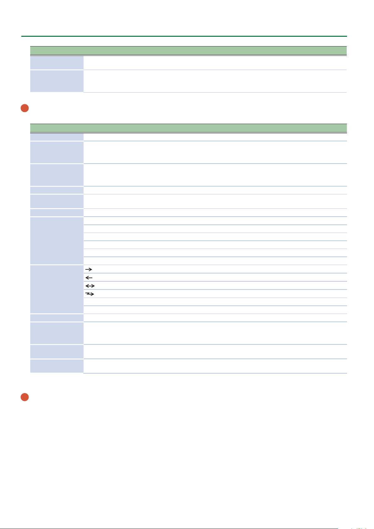
Species whether MIDI messages received via the USB COMPUTER
port/MIDI IN connector will be re-transmitted from the MIDI OUT
connector/USB COMPUTER port (ON) or not be re-transmitted
(OFF).
USBMIDI Thru=OFF
MIDI
OUT
MIDI INUSB
OUT
USB
IN
USBMIDI Thru OFF, ON
USBMIDI Thru=ON
MIDI
OUT
Sound
Generator
Section
MIDI INUSB
OUT
Sound
Generator
Section
SYSTEM-8
USB
IN
SYSTEM-8
19
Page 20

Making System Settings (SYSTEM Setting Screen)
Menu
[SHIFT] +cursor [K] [J]
MIDI Soft Thru OFF, ON
MIDI Tx
MIDI Rx
CV/GATE OUT
Parameter
Cursor [K] [J]
Tx Prog Chg OFF, ON
Tx Bank Sel OFF, ON
Tx Edit Data OFF, ON
Rx Prog Chg OFF, ON
Rx Bank Sel OFF, ON
Rx Edit Data OFF, ON
Scale -100–0–+100 Adjusts the scale of the CV.
Fine Tune -100–0–+100
Ref Note C0, C1, C2, C3, C4
Src
Bend Range 1–24
Portamento
PortTime 0–127
Value
[VALUE] knob
ALL
KBD (L) Keyboard performance data of the lower part is output.
KBD (U) Keyboard performance data of the upper part is output.
KBD (U&L) Keyboard performance data is output.
STEP SEQ (L) Step sequencer performance data of the lower part is output.
STEP SEQ (U) Step sequencer performance data of the upper part is output.
PATCH (L) The behavior of the lower part's sound engine is output.
PATCH (U) The behavior of the upper part's sound engine is output.
USB OMNI The note data of all USB MIDI channels is combined and output.
USB CH1–USB CH16 The note data of a specied USB MIDI channel is output.
MIDI IN OMNI The note data of all MIDI IN channels is combined and output.
MIDI IN CH1–MIDI IN
CH16
OFF Portamento is not applied.
ALWAYS Portamento is always applied.
LEGATO
Explanation
If this is ON, MIDI messages that are input from the MIDI IN
connector are retransmitted without change from the MIDI OUT
connector.
Species whether program change messages will be transmitted
(ON) or not be transmitted (OFF).
Species whether bank select messages will be transmitted (ON)
or not be transmitted (OFF).
Species whether changes in patch settings (panel operations) are
transmitted as MIDI messages (ON) or not transmitted (OFF).
Species whether program change messages will be received (ON)
or not be received (OFF).
Species whether bank select messages will be received (ON) or
not be received (OFF).
Species whether the data that is output when editing a patch is
received (ON) or not received (OFF).
Adjusts the 0 V of the CV OUT.
* This value will uctuate slightly if the Scale value is changed.
Species the note number at which the CV OUT is 0 V, in units of
octaves.
Keyboard (both upper and lower), step sequencer (both upper and
lower), USB (OMNI), and MIDI IN (OMINI) data are output.
The note data of a specied MIDI IN channel is output.
Species the amount (in semitone units, up to two octaves) of
pitch change that occurs when you move the pitch bend lever.
Portamento is applied when you hold down a key and press
another key.
When portamento is used, this species the time over which the
pitch will change.
20
Page 21

Making System Settings (SYSTEM Setting Screen)
Menu
[SHIFT] +cursor [K] [J]
INPUT
INPUT (Vocoder)
* Parameters for
vocoder-related
settings.
Parameter
Cursor [K] [J]
Gain -20dB, -10dB, 0dB, +10dB Species the input sensitivity of the external input.
DelayType
Delay Time 0–255 Adjusts the time by which the sound is delayed.
DeLay Level OFF, 1–255 Adjusts the volume of the delay/chorus sound.
ReverbType
Reverb Time 0–255 Adjusts the length of the reverb decay.
Reverb Level OFF, 1–255 Adjusts the volume of the reverb sound.
Formant 0–255 Species the formant (vocal character).
Consonant -40dB–0dB–+40dB Species the volume of the consonants.
Balance D128–0–W127
Value
[VALUE] knob
(DELAY),
DLY
PAN
(PANNING DELAY),
CH1
(CHORUS 1),
CH2
(CHORUS 2),
FL
(FLANGER),
DLY+CH
AMBI
ROOM
HALL1
HALL2
PLATE
MOD
(DELAY + CHORUS)
(AMBIENCE),
(ROOM),
(HALL 1),
(HALL 2),
(PLATE),
(MODURATION)
Explanation
Switches the delay/chorus type.
Switches the reverb type.
D128: Mic input (direct sound) only
0: Mic input and vocoder sound are at the same volume
W127: Vocoder sound only
Saving the System Settings
1. Press the [WRITE] button.
The WRITE screen appears.
<WRITE> [Ent]
ÄSYSTEM*
2. Press the cursor [
A conrmation message appears.
System Write?
[Exit]:N [Ent]:Y
3. To save, press the [ENTER] button.
If you decide to cancel, press the [EXIT] button.
When saving is completed, the display indicates “Write Completed!”
Write Completed!
* NEVER turn the power o while you are saving settings.
MEMO
You can also save the system settings by pressing the [WRITE] button in the system setting screen.
J
] button several times to select “SYSTEM,” and then press the [ENTER] button.
21
Page 22

Viewing the System Version (VERSION INFO)
Here’s how to view the version of the SYSTEM-8’s system program.
1. Press the [MENU] button.
2. Select “VERSION INFO” and then press the [ENTER]
button.
The SYSTEM-8’s version is shown.
VERSION INFO
Version 1.02
Viewing Plug-Out Information (PLUG-OUT INFO)
Here’s how to view information on the currently loaded plug-outs.
1. Press the [MENU] button.
2. Choose “PLUG-OUT INFO” and press the [ENTER]
button.
Information on the currently loaded plug-outs is shown.
PLG1:Ver. 1.01À
JUPITER-8
3. Use the cursor [
button (PLUG-OUT 1–3) to be shown.
MEMO
From “PLUG-OUT 3,” you can then press the cursor [J]
button to view pre-load plug-out information for PLUG-OUT1
and 2 in the same way.
ÄPRE1:Ver. 1.01À
JUPITER-8
What does pre-load mean?
These are plug-outs that are already installed in the SYSTEM-8.
If you later installed a dierent plug-out by overwriting a pre-load
plug-out, removing the plug-out you installed will bring back the
pre-load plug-out.
&
“Removing a PLUG-OUT (PLUG-OUT REMOVE)” (p. 25)
K
] [J] buttons to select the MODEL
22
Page 23

Convenient Functions (UTILITY)
Backing Up Data to SD Card (BACKUP)
1. Press the [MENU] button.
2. Use the Cursor [
and then press the [ENTER] button.
3. Use the Cursor [
and then press the [ENTER] button.
K
] [J] buttons to select “UTILITY,”
K
] [J] buttons to select “BACKUP,”
4. Assign a le name to the backup.
BACKUP NAME[Ent]
Sys8_bak .bin
Use the cursor [K] [J] buttons to move the cursor.
Use the [VALUE] knob to select the character.
5. Press the [ENTER] button.
A conrmation message appears.
Backup?
[Exit]:N [Ent]:Y
MEMO
If a backup le with the same le name already exists, the
conrmation message “Overwrite?” appears.
6. To back up, press the [ENTER] button.
If you decide to cancel, press the [EXIT] button.
When the backup is completed, the screen indicates “Completed!”
Restoring Data That Was Backed Up to SD Card (RESTORE)
NOTE
All data and settings are rewritten when you execute the
restore operation. If your SYSTEM-8 contains important data,
assign it a dierent name and back it up to an SD card before
you restore.
1. Press the [MENU] button.
2. Use the Cursor [
and then press the [ENTER] button.
3. Use the Cursor [
and then press the [ENTER] button.
4. Use the [VALUE] knob to select the le that you
want to restore.
RESTORE [Ent]
sys8_bak.bin
5. Press the [ENTER] button.
A conrmation message appears.
Restore?
[Exit]:N [Ent]:Y
K
] [J] buttons to select “UTILITY,”
K
] [J] buttons to select “RESTORE,”
1
File name
6. To restore, press the [ENTER] button.
If you decide to cancel, press the [EXIT] button.
When the restore is completed, the screen indicates “Completed!”
Completed!
Turn off power.
7. Turn the power of the SYSTEM-8 o, then on again.
Exporting Sound Data to an SD Card (EXPORT)
If you want to export a patch, press the MODE [PATCH] button to
select patch mode.
If you want to export a performance, press the MODE
[PERFORMANCE] button to select performance mode. Exporting
a performance creates a single le that also includes the patches
used by that performance.
1. Press the [MENU] button.
2. Use the Cursor [
and then press the [ENTER] button.
3. Use the Cursor [
and then press the [ENTER] button.
The export target selection screen appears.
A-1 [Ent]:Sel
SY System-8 Saws
4. Use the [VALUE] dial to select the patch/
performance that you want to export, and press the
[ENTER] button to mark it.
Marking the data adds a “ ( “ at the left of the Bank-Number. If the
data is already marked, the mark is removed.
A-1 [Ent]:Sel>
SY System-8 Saws
You can also select a patch/performance by using the [A]–[H] and
[1]–[8] buttons.
You can select multiple patches/performances and export them as
a single le.
In patch mode, you can select patches of dierent models and
export them as a single le.
5. Press the cursor [
Here you can verify the number of patches/performances that you
selected.
<COUND: 4[Ent]
sys8_pat .s8p
If you want to return to the export target select screen, press the
cursor [K] button.
About the le name
If a single patch/performance is selected, the patch/performance
name (the rst 12 characters) + extension is shown.
The le name extension is .s8p for a patch export le, or .s8f for a
performance export le.
K
] [J] buttons to select “UTILITY,”
K
] [J] buttons to select “EXPORT,”
J
] button.
23
Page 24

Convenient Functions (UTILITY)
6. Press the [ENTER] button.
Specify the le name of the export le.
EXPORT NAME[Ent]
sys8_pat .s8p
Use the cursor [K] [J] buttons to move the cursor.
Use the [VALUE] knob to choose characters.
7. Press the [ENTER] button.
A conrmation message appears.
Export?
[Exit]:N [Ent]:Y
If an export le with the same le name exists, a conrmation
message of “Overwrite?” appears.
8. To export, press the [ENTER] button.
If you decide to cancel, press the [EXIT] button.
When the export is completed, the message “Completed!”
appears.
Importing Sound Data from an SD Card (IMPORT)
5. Press the [ENTER] button.
The sound data selection screen appears. Use the [VALUE] knob to
select the sound data that you want to import.
If you’re importing patch data, you can use the MODEL [SYSTEM-1]
[PLUG-OUT 1] [PLUG-OUT 2] [PLUG-OUT 3] buttons to select the
target model.
If you’re importing patch data, the MODEL (SYS8, PLG1, PLG2,
PLG3) is shown. If you’re importing performance data, the screen
indicates PERF.
If you’re importing from a backup le, or if you’re
importing a patch from a performance backup le,
the original Bank-Number are shown.
If you’re importing from an export le, the number
of patches or performances of the selected model
in that le is shown.
SYS8: 1/4[Ent]
SY System-8 Saws
6. Press the [ENTER] button.
The data is loaded temporarily, and a conrmation screen appears.
You can play the keyboard to audition the sound.
If you want to import a patch, press the MODE [PATCH] button to
select patch mode.
If you want to import a performance, press the MODE
[PERFORMANCE] button to select performance mode.
1. Press the [MENU] button.
2. Use the Cursor [
and then press the [ENTER] button.
3. Use the Cursor [
and then press the [ENTER] button.
The import target (BACKUP, EXPORT) selection screen appears.
Use the [VALUE] knob to choose whether to import from a backup
le or from an export le.
IMPORT: [Ent]
Src BACKUP
Import target
Scr
BACKUP Import from a backup le
EXPORT Import from an export le
EXPORT (Perf)
K
] [J] buttons to select “UTILITY,”
K
] [J] buttons to select “IMPORT,”
Explanation
Import from a performance export le
* Only in patch mode
4. Press the [ENTER] button.
The le selection screen appears. Use the [VALUE] knob to select
the le that you want to import.
Import?
[Exit]:N [Ent]:Y
7. To import the data, press the [ENTER] button.
If you decide to cancel, press the [EXIT] button.
When the import is completed, the patch or performance top
screen appears.
* When you import a performance, the patches themselves are not
imported. As needed, you should import the patches individually
from the same le.
8. To save the sound data on the SYSTEM-8, press the
[WRITE] button to execute the procedure “Saving a
Sound” (owner’s manual p. 11).
Simply executing import does not write the data into the
SYSTEM-8’s memory; as when you edit a sound, the changed values
are temporary.
If you want to save the data in the SYSTEM-8’s memory, you must
save the sound.
Changing the Order of Patches/Performances (EXCHANGE)
You can change the order of the patches or performances as you
like.
If you want to change the order of patches, press the MODE
[PATCH] button to select patch mode. If you want to change the
order of performances, press the MODE [PERFORMANCE] button
to select performance mode.
IMPORT: [Ent]
sys8_pat.s8p
24
Page 25

Convenient Functions (UTILITY)
1. Press the [MENU] button.
2. Use the Cursor [
and then press the [ENTER] button.
The UTILITY screen appears.
UTILITY [Ent]
BACKUP À
3. Use the cursor [
“EXCHANGE,” and then press the [ENTER] button.
EXCHANGE [Ent]
SYS8: A-1 ÄÀ A-1
If you’re exchanging patches, use the MODEL buttons to select the
model of patches that you want to exchange.
4. Use the [VALUE] knob and the cursor [
to select the patches/performances that you want to
exchange.
K
] [J] buttons to select “UTILITY,”
K
] [J] buttons to select
K
] [J] buttons
5. Press the [ENTER] button.
A conrmation message appears.
Exchange?
[Exit]:N [Ent]:Y
6. To execute, press the [ENTER] button.
If you decide to cancel, press the [EXIT] button.
When the exchange is completed, the display indicates
“Completed!”
Completed!
4. Use the [VALUE] knob to select the item that you
want to factory-reset.
Item
[VALUE] knob
ALL
EXCEPT PLUGOUT
SYSTEM-8
PATC H
PLUG-OUT 1
PLUG-OUT 2
PLUG-OUT 3
Explanation
All of the SYSTEM-8’s settings/patches/
performances, including PLUG-OUT 1–3, are
reset to their factory-set state.
Only the SYSTEM-8’s settings/patches/
performances, and not PLUG-OUT 1–3, are
reset to their factory-set state.
Only the SYSTEM-8’s patches are reset to their
factory-set state.
Only the patches of a synthesizer installed in
PLUG-OUT 1–3 are reset to their factory-set
state.
5. Press the [ENTER] button.
A conrmation message appears.
Factory Reset?
[Exit]:N [Ent]:Y
6. To execute, press the [ENTER] button.
If you decide to cancel, press the [EXIT] button.
When the factory reset is completed, the screen indicates
“Completed!”
Completed!
Turn off power.
7. Turn the power of the SYSTEM-8 o, then on again.
NOTE
If you exchange a patch that is used by a performance, that
performance will no longer be reproduced.
Returning to the Factory Settings (FACTORY RESET)
1. Press the [MENU] button.
2. Use the Cursor [
and then press the [ENTER] button.
The UTILITY screen appears.
UTILITY [Ent]
BACKUP À
3. Use the cursor [
RESET,” and then press the [ENTER] button.
Sel Target [Ent]
ALL
K
] [J] buttons to select “UTILITY,”
K
] [J] buttons to select “FACTORY
Removing a PLUG-OUT (PLUG-OUT REMOVE)
1. Press the [MENU] button.
2. Use the Cursor [
and then press the [ENTER] button.
The UTILITY screen appears.
3. Use the cursor [
REMOVE,” and press the [ENTER] button.
If there are only the pre-load plug-outs, there are no plug-outs to
remove, so the display indicates “Empty!”
Empty!
K
] [J] buttons to select “UTILITY,”
K
] [J] buttons to select “PLUG-OUT
25
Page 26

Convenient Functions (UTILITY)
4. Press the [PLUG-OUT 1]–[PLUG-OUT 3] button of
the PLUG-OUT that you want to remove.
The PLUG-OUT name is shown. If you want to select it as the PLUGOUT to remove, press the [ENTER] button.
SelectModel[Ent]
PLG1:PlugOutName
A conrmation message appears.
PLUG-OUT Delet?
[Exit]:N [Ent]:Y
5. To remove the PLUG-OUT, press the [ENTER] button.
If you decide to cancel, press the [EXIT] button.
When the PLUG-OUT is removed, the screen indicates
“Completed!”
Formatting an SD Card (SD CARD FORMAT)
SD cards are sold separately. Please obtain a SD card separately.
* Never turn o the power or remove the memory card during the
execution of the “WRITE” or “BACKUP.”
* Carefully insert the memory cards all the way in—until it is rmly
in place.
* Depending on the manufacturer or type of memory card, it
might not be possible for the SYSTEM-8 to correctly save or read
data on the card.
* The memory card write protect
feature (LOCK)
The contents of the memory
card can be protected by write
protecting it.
To write protect a card, slide the
write protect switch on the side of
the memory card to the “LOCK”
position. Unlock write protect to write data to the card.
* All memory cards eventually wear out. We recommend that you
consider the memory card not as a permanent storage site, but
as a place to store data temporarily. We also recommend that
you back up important data onto other media that is supported
by your unit.
Write protect switch
SD card folder structure
[SD CARD]
ROLAND folder
SYSTEM-8 folder
BACKUP folder
Contains backup data (extension: .bin).
EXPORT folder
PATCH folder
Contains exported patch data (extension: .s8p).
PERFROM folder
Contains exported performance data
(extension: .s8f).
* When you execute backup or export, the backup le or export
le is saved, and a text le (.txt) listing the contents of that le is
also saved at the same time.
Deleting a File from an SD Card (Delete File)
Here’s how to delete a backup le or export le from an SD card.
1. In the “RESTORE” or “IMPORT” le selection screen,
press the STEP SEQUENCER section’s [REST] (ERASE)
button.
A conrmation message appears.
Delete File?
[Exit]:N [Ent]:Y
2. To delete the le, press the [ENTER] button.
If you decide to cancel, press the [EXIT] button.
When deletion is complete, the screen indicates “Completed!”
1. Press the [MENU] button.
2. Use the Cursor [
and then press the [ENTER] button.
3. Use the cursor [
FORMAT,” and then press the [ENTER] button.
A conrmation message appears.
Format SD Card?
[Exit]:N [Ent]:Y
K
] [J] buttons to select “UTILITY,”
K
] [J] buttons to select “SD CARD
4. To execute formatting, press the [ENTER] button.
If you decide to cancel, press the [EXIT] button.
Formatting is completed when the screen indicates “Completed!.”
26
Page 27

Overwrite-Saving Edited Data (Overwrite)
Separately from the conventional write operation (saving sound
data in the “WRITE” screen that appears when you press the
[WRITE] button), there is also an “OVERWRITE” function that
overwrite-saves to the currently selected bank and number.
In performance mode, this lets you save not only the performance
but also the patches of the upper part and lower part, making it
convenient when you want to save this data in a single operation.
1. Hold down the [SHIFT] button and press the
[WRITE] button.
A conrmation message appears.
Overwrite?
[Exit]:N [Ent]:Y
2. To overwrite-save, press the [ENTER] button.
If you decide to cancel, press the [EXIT] button.
When saving is complete, the screen indicates “Completed!”
NOTE
In performance mode, the patches of the upper part and
lower part are also overwrite-saved.
Convenient Functions (UTILITY)
27
Page 28

Using the Vocoder (VOCODER)
“Vocoder” is an eect that is applied to a human voice. By sending a human voice through a vocoder, you can give it an expressionless vocal
character as though a robot were speaking. Control the pitch by playing the keyboard.
Connecting a Mic
3. Use the [INPUT] knob to adjust the input level.
1. Connect a dynamic microphone to the INPUT L/
MONO jacks.
2. Set the INPUT [GAIN] switch to the “MIC” position.
1. While vocalizing into the mic, use the [INPUT] knob to adjust the mic
volume.
2. Adjust the system setting INPUT: Gain parameter (p. 21) so that this
indicator lights occasionally.
Using the Vocoder in Patch Mode
1. Press the MODE [PATCH] button to select patch mode.
2. Press the [VOCODER] button to turn it "on" (lit).
3. While vocalizing into the input (Microphone), play the keyboard.
You can perform the vocoder sound that’s generated according to the currently selected patch and the input audio.
5 Input settings including the vocoder settings are made in the system settings.
5 If the [VOCODER] button is “on,” the audio of the patch itself and the audio of the input (Microphone) are not output.
5 The [VOCODER] button’s on/o setting is not saved in the patch.
[VOCODER]
button
INPUT
SYSTEM setting
INPUT: Gain
PEAK LED
[INPUT]
knob
VOCODER
DELAY
CHORUS
REVERB
PATCH MODE
28
OUTPUT
PATCH
Page 29

Using the Vocoder (VOCODER)
Using the Vocoder in Performance Mode
1. Press the MODE [PERFORMANCE] button to select performance mode.
2. Press the [VOCODER] button to turn it “on” (lit).
3. While vocalizing into the input (Microphone), play the keyboard.
You can perform the vocoder sound that’s generated according to the currently selected patch and the input audio.
5 Input settings including the vocoder settings can be made and stored for each individual performance.
5 Input settings including the vocoder operate dierently depending on the setting of the “PERFORM EDIT: INPUT: Prm Src” parameter.
If this is set to “PERFORM,” the performance settings are used. The [VOCODER] button’s on/o status is also remembered.
If this is set to “SYSTEM,” the system settings are used. The [VOCODER] button’s on/o status is not remembered.
5 The part used as the vocoder’s carrier can be specied and remembered for each performance by the “PERFORM EDIT: INPUT (Voc):
Carrier” parameter.
When the PerfMode Is “DUAL”
When the PerfMode (p. 11) is set to “DUAL,” operation is as follows.
5 When you turn the [VOCODER] button "on,"
The input (Microphone) audio is not output.
The audio of the upper part and lower part patches is output according to the on/o status of the PART ON/OFF [UPPER] [LOWER]
buttons.
5 If you want to play only the vocoder sound, press the PART ON/OFF [UPPER] [LOWER] buttons to make them go dark.
INPUT
PERFORMANCE MODE
SYSTEM setting
INPUT: Gain
UPPER PART
LOWER PART
PEAK LED
PATCH
PATCH
[INPUT]
knob
ON/OFF
[UPPER]
[LOWER]
PART
Button
[VOCODER]
button
VOCODER
PERF EDIT
INPUT (Voc): Carrier
DELAY
CHORUS
REVERB
OUTPUT
29
Page 30

Using the Vocoder (VOCODER)
When the PerfMode Is “SINGLE”
When the PerfMode (p. 11) is set to "SINGLE," operation is as follows.
5 When you turn the [VOCODER] button "on,"
The input (Microphone) audio is not output.
The audio of the upper part and lower part patches is not output.
INPUT
SYSTEM setting
INPUT: Gain
PEAK LED
[INPUT]
knob
[VOCODER]
button
VOCODER
DELAY
CHORUS
REVERB
PERFORMANCE MODE
UPPER PART
LOWER PART
PATCH
PATCH
PART
ON/OFF
[UPPER]
[LOWER]
Button
OUTPUT
PERF EDIT
INPUT (Voc): Carrier
30
Page 31

About the Step Sequencer
STEP SEQUENCER
This is a polyphonic step sequencer.
The following settings are stored individually for each patch.
5 Performance data (notes, knob operations) of each step, each
step’s mute settings
5 [SCALE] knob, [PLAY MODE] knob, [GATE] knob, and [SHUFFLE]
knob settings
5 Step length value
5 Step position of the rst step and last step
In performance mode, you can use two tracks: the upper part and
lower part. Other than sharing the [PLAY] button, the [FIRST STEP]
button and the [LAST STEP] button all data is independent for the
upper and lower parts; the settings and performance data for the
patches are independent. To record or to edit the settings, use the
PANEL SELECT buttons to select the applicable part, just as when
editing a patch.
* In performance mode if Key Range is specied for each part,
the previously-recorded performance data is played back, but
keyboard performance outside the specied Key Range is not
recorded on the step sequencer.
Recording Steps Consecutively (STEP REC)
Here’s how you can create step sequencer data by successively
recording each individual step of your keyboard performance.
1. If you’re in performance mode, use the PART SELECT
[UPPER] [LOWER] buttons to select the part that you
want to record.
2. Press the [STEP REC] button.
The rst step blinks.
3. Play one note on the keyboard.
MEMO
5 The note you play is recorded in step 1; you then
automatically advance to step 2, and the [2] button blinks.
5 By selecting multiple notes without releasing, you can record
a chord.
Keyboard recording screen
Step number
REC: STEP 1
C4 E4 G4 ---
Note number
5 You can use the [GATE] knob to specify the gate time. While
holding down the key, operate the [GATE] knob.
REC: STEP 1
GATE Time: 50%
Name of parameter
No recorded data
FILTER:Cutoff
oo [100] -- --
Knob operations
are recorded
Currently-input value
4. Repeat step 3 to record onto each step.
MEMO
5 The step does not advance while any key is held down; this
allows you to re-enter the note or gate time of the step that
you’re recording. When all keys are released, you’ll advance to
the next step.
5 If you press the [TIE] button while holding down a key, you’ll
move to the next step while maintaining the state of the
currently-pressed keys; if you then release the key, the two
steps are connected by a tie.
5 You can use the damper pedal during keyboard input.
Pressing the pedal maintains the state of the currentlypressed keys, and releasing the pedal is the equivalent of
releasing the keys.
5 To specify a rest for a step, press the [REST] button to specify
a rest (=unrecorded state) for that step and advance to the
next step.
5 To erase the data from a step, press the [EDIT/DISP] + [REST
(ERASE)] buttons, and in the ERASE screen choose “STEP” to
execute.
5 To enter a tie, hold down a key and press the [TIE (LENGTH)]
button. The tie is entered, and you advance to the next step.
5 During recording, you can press a [1]–[16] button to re-
record from that step.
5 When you step-record on a previously-recorded step, the
note data is replaced and the knob operations are added.
5 When the [EDIT/DISP] button is lit, you can hold down the
[SHIFT] button and press one of the STEP [1]–[4] buttons to
change the area of steps from which to select.
5 Step recording ends when you reach the step specied by the
step length setting.
5. Press the [STEP REC] button to stop recording.
When you input the last step, step recording ends automatically.
As necessary, save the step sequencer data.
&
“Saving Step Sequencer Data” (p. 33)
Recording in Real Time (REAL TIME REC)
Here’s how you can create step sequencer data by recording your
keyboard performance in real time. The recorded data is layered
onto the step sequencer data that’s selected.
MEMO
Step sequencer data is saved within the patch data.
5 You can record knob operations. While holding down a key,
operate a knob. You can record up to four knob operations.
Knob recording screen
1. Press the [EDIT/DISP] button to make it light.
2. In performance mode, use the PART SELECT [UPPER]
[LOWER] buttons to select the part that you want to
record.
3. Press the [REALTIME REC] button.
4. Press the [START] button to start recording.
You can also start recording by pressing the [REAL TIME REC]
button during playback.
31
Page 32

About the Step Sequencer
5. Play the keyboard.
You can also record chords.
Knob operations are also recorded.
MEMO
5 You can loop-record while adding notes and knob operations
to the existing data.
5 If you exceed the maximum number of recordable notes (8)
or knob operations (4), the oldest data is successively erased
and overwritten.
6. Press the [REAL TIME REC] button to stop recording.
As necessary, save the step sequencer data.
&
“Saving Step Sequencer Data” (p. 33)
Starting Realtime Recording by Keyboard Input
1. Hold down the [SHIFT] button and press the [REAL
TIME REC] button.
The [REAL TIME REC] button and [PLAY] button blink.
2. Play the keyboard.
The moment you press a key, the [PLAY] button lights and realtime
recording starts.
You can also record chords.
Knob operations are also recorded.
MEMO
5 For both notes and knob operations, loop recording occurs
while adding to the existing data.
5 If you exceed the maximum number of recordable notes (8)
or knob operations (4), the oldest data is successively erased
and overwritten.
3. Press the [REAL TIME REC] button to stop recording.
As necessary, save the step sequencer data.
&
“Saving Step Sequencer Data” (p. 33)
Editing a Specic Step
1. Press the [EDIT/DISP] button to make it light.
2. Hold down the [EDIT/DISP] button and press the
[1]–[16] button that you want to edit.
The screen shows the recorded notes.
EDIT: STEP 1
C4 E4 G4 ---
3. Press the key (or operate the knob) that you want to
record.
If you press a key, the previously-recorded notes are erased and
overwritten. (During editing, releasing the key does not advance
the step.)
If you operate a knob, the data is added. (During editing, knob
operations can be recorded or edited even without pressing a key.)
4. Use the cursor [
parameter that you want to edit, and then operate
the knob.
FILTER:Cutoff
oo [100] -- --
You can also use the [VALUE] knob to edit the value of the
applicable parameter.
This lets you newly record a knob operation.
MEMO
5 You can use the cursor [K] [J] buttons to move to the note
screen or knob recording screen. The knob recording screen
changes for each of the four parameters that are recorded.
5 If you press the [REST/ERASE] button, the data that is shown/
selected is deleted.
K
] [J] buttons to select the
Recording a Specic Step
1. Press the [EDIT/DISP] button to make it light.
2. Hold down the [1]–[16] button that you want to
record, and play the key (or operate the knob) that
you want to record.
3. Release the [1]–[16] button.
Recording ends.
MEMO
5 You can record even while the step sequencer is playing.
5 If recorded data exists in the step you recorded, the new data
is added. In the same way as in “REAL TIME REC,” the most
recent eight notes are retained. If knob operations exceed
four, the display indicates “Prm Memory Full.”
32
5. Press the [EDIT/DISP] button.
Editing ends.
Transposing the Playback
1. Hold down the [EDIT/DISP] button and press one of
the C3–C5 keys.
You can transpose in a range of one octave upward or downward.
STEP SEQ T=120.0
U:*--- 1-16
If the playback is transposed, the upper right of the STEP SEQ
screen alternately show the tempo indication and the transpose
value.
Hold down the [EDIT/DISP] button and press the C4 key to cancel
transposition.
STEP SEQ CÀ+F
U:*--- 1-16
Muting the Playback of a Specic Part (Performance
Mode Only)
1. Hold down the [EDIT/DISP] button, and press the
PART ON/OFF [UPPER] or [LOWER] button.
The performance of the part you pressed is muted.
To unmute the part, perform the same operation once again.
Page 33

About the Step Sequencer
Saving Step Sequencer Data
Step sequencer data is saved within the patch data. You can save
(overwrite) just the step sequencer data without writing the sound
settings of the patch.
1. In performance mode, use the PART SELECT [UPPER]
[LOWER] buttons to select a part that you want to
save.
2. Hold down the [EDIT/DISP] button and press the
[WRITE] button.
A conrmation message appears.
<WRITE> [Ent]
ÄSEQ:Upper*
3. To save, press the [ENTER] button.
If you decide to cancel, press the [EXIT] button.
When saving is completed, the display indicates “Completed!”
Completed!
1. While holding down [LAST STEP], press the button
that you want to be the last step.
MEMO
You can also specify this by holding down the [LAST STEP]
button and using the [VALUE] knob.
The [LAST STEP] button is lit, and the last step is specied. You
can use this operation to make it play to any desired step and then
return to the rst step.
If you press the [LAST STEP] button to make it go dark, the LAST
STEP setting turns o (the specied setting remains).
Changing the Steps While Maintaining the Spacing of the First and Last Steps
1. Hold down both the [FIRST STEP] button and the
[LAST STEP] button, and turn the [VALUE] knob.
FIRST 1 LAST 8
*--- 1-16
This changes the two values simultaneously while maintaining the
spacing between the FIRST STEP and LAST STEP.
About FIRST STEP and LAST STEP
Selecting the First Step (FIRST STEP)
Normally, step 1 is played as the rst step; however, you can use the
FIRST STEP setting to make the step sequencer use a dierent step
as the rst step.
Step
1–16
FIRST STEP LAST STEP
1. While holding down [FIRST STEP], press the button
that you want to be the rst step.
MEMO
You can also specify this by holding down the [FIRST STEP]
button and using the [VALUE] knob.
The [FIRST STEP] button is lit, and the rst step is specied. You
can use this operation to make it play from any desired step.
If you press the [FIRST STEP] button to make it go dark, the FIRST
STEP setting turns o (the specied value remains).
Selecting the Last Step (LAST STEP)
Step
17–32
Playback region
Step
33–48
Step
49–64
STEP SEQ MENU
Here’s how to copy a step sequencer pattern, and how to specify
the note length of one step.
1. Press the [MENU] button.
2. Select “STEP SEQ MENU” and then press the
[ENTER] button.
The SEQ MENU screen appears.
<SEQ MENU> [Ent]
PTN COPY À
Menu
Cursor [K] [J]
PTN COPY Copies a pattern.
SETTING Species the note length of one step.
Copying a Pattern (PTN COPY)
1. In the SEQ MENU screen, select “PTN COPY” and
press the [ENTER] button.
<SEQ MENU> [Ent]
PTN COPY À
Explanation
Normally, the step specied by STEP LENGTH is played as the last
step; however, you can use the LAST STEP setting to make the step
sequencer use a dierent step as the last step.
If you’re in performance mode, select the copy-source part
(upper/lower).
Lower part
<SEQ MENU> [Ent]
PTN COPY [L] À
Upper part
<SEQ MENU> [Ent]
ÄPTN COPY [U] À
33
Page 34

About the Step Sequencer
2. Use “From:” to select the copy-source patch
number, and press the [ENTER] button.
PTN COPY [Ent]
From:SYS8 A-1
3. At the conrmation screen, press the [ENTER]
button.
If you decide to cancel, press the [EXIT] button.
Specifying the Note Length of One Step (SETTING)
1. In the SEQ MENU screen, select “SETTING” and press
the [ENTER] button.
SETUP:
Default Gate 50
2. Specify the “Default Gate” value.
Parameter
Default Gate 1–100
* This parameter is initialized when you turn o the power (default
value: 50).
Value
[VALUE] knob
Explanation
Species the note length of
each step (default value: 50).
If this is 100, the note
continues sounding until the
end of the step.
34
 Loading...