

Page 1
505
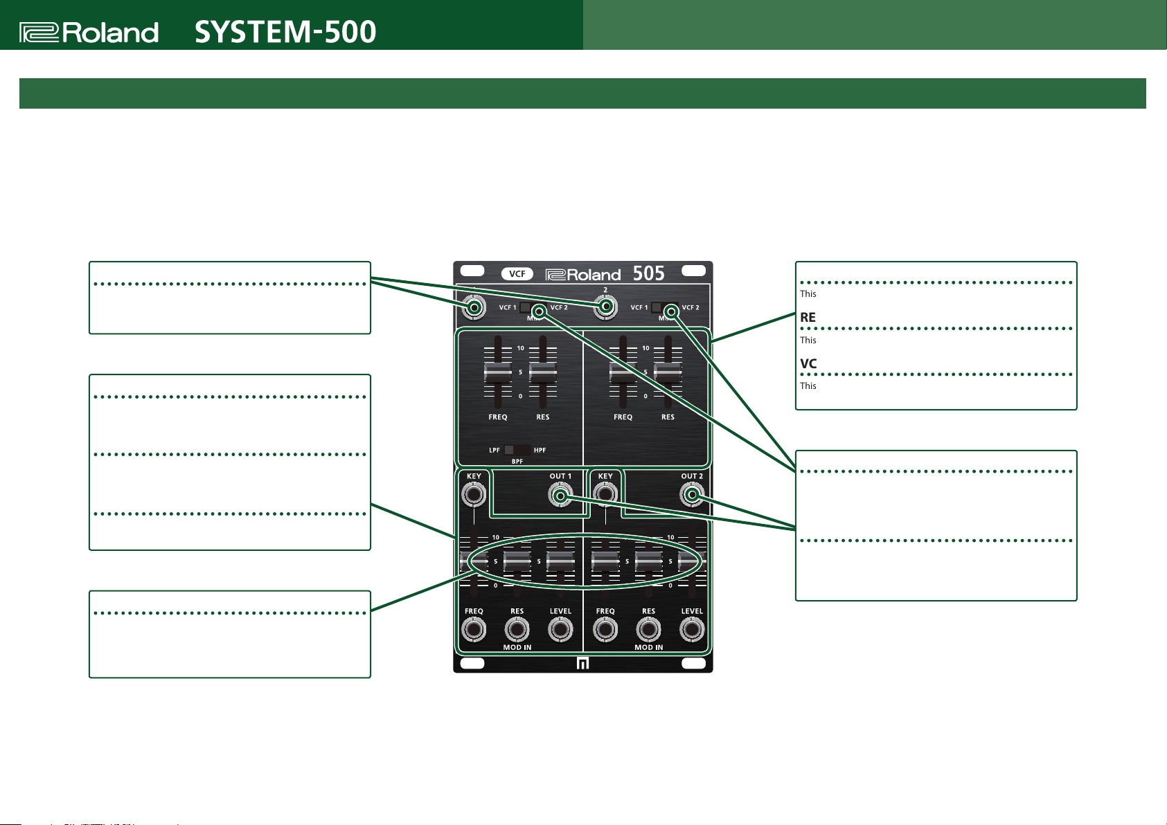
The Parameters of the 505
The 505 is a module equipped with two VCFs and two VCAs.
The two VCFs are the VCF1 multi-mode lter (LPF, BPF, HPF) and the VCF2 BPF.
By setting the switches located in the upper part of the panel, you can specify either VCF1, VCF2, or a mix of both as the signal that is input to each VCA.
Copyright © 2018 ROLAND CORPORATION
SIG IN 1/2
These jacks input audio signals.
The signals of both SIG IN1 and 2 are input to both VCF1 and VCF2.
MOD IN KEY/FREQ
This jack inputs a voltage that controls the cuto frequency of the
VCF.
MOD IN RES
This jack inputs a voltage that controls the resonance of the VCF
MOD IN LEVEL
This jack inputs a voltage that controls the volume of the VCA.
CV input attenuator
These sliders adjust the gain of the voltages that are input from the
MOD IN FREQ/RES/LEVEL jacks.
If nothing is connected to the LEVEL jack, 12V is supplied to LEVEL,
allowing it to adjust the output volume from the OUT jack.-
FREQ (Cuto frequency)
This slider adjusts the cuto frequency of the lter.
RES (Resonance)
This slider boosts the frequency region near the cuto frequency.
VCF1 MODE SW
This switch selects either LPF, BPF, or HPF as the lter type for VCF1.
OUTPUT SELECT SW
These switches select the signals that are output from the OUT
jacks. The signals that you select here are output after passing
through the VCA.
OUT 1/2
These are the output jacks. Each jack outputs the signal from the
corresponding VCF as selected by the OUTPUT SELECT SW and
processed through the VCA.
01
Page 2
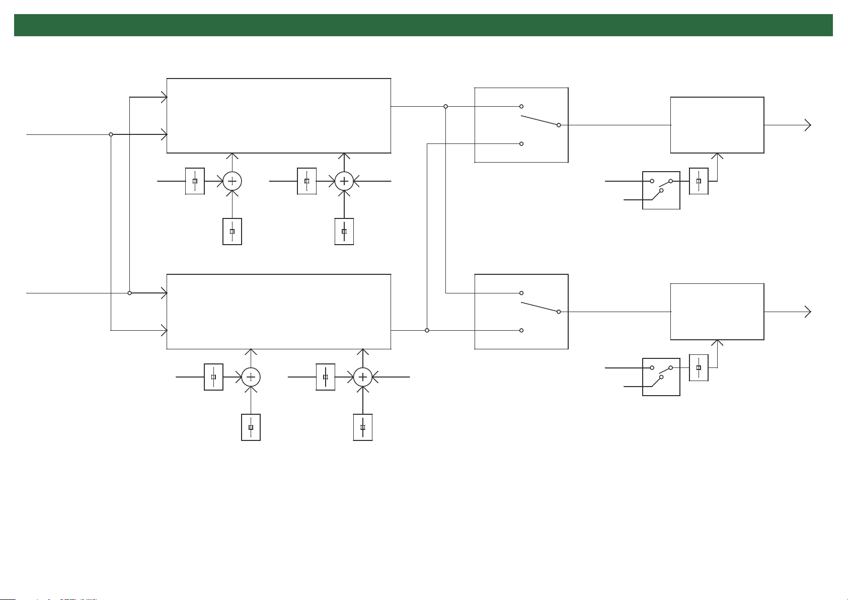
Block Diagram
SW
Input 1
Input 2
VCF 1
Multi Mode Filter
Slider
RES
Slider
VCF 2
Band Pass Filter
Slider
Slider
FREQ
VCF 1
Mix
VCF 2
MOD IN KEYFREQRES
SW
VCF 1
Mix
VCF 2
MOD IN KEYFREQRES
Level
12v
Level
12 v
Jack
Jack
VCA 1
Slider
VCA 2
Slider
OUT 1
OUT 2
RES
FREQ
 Loading...