

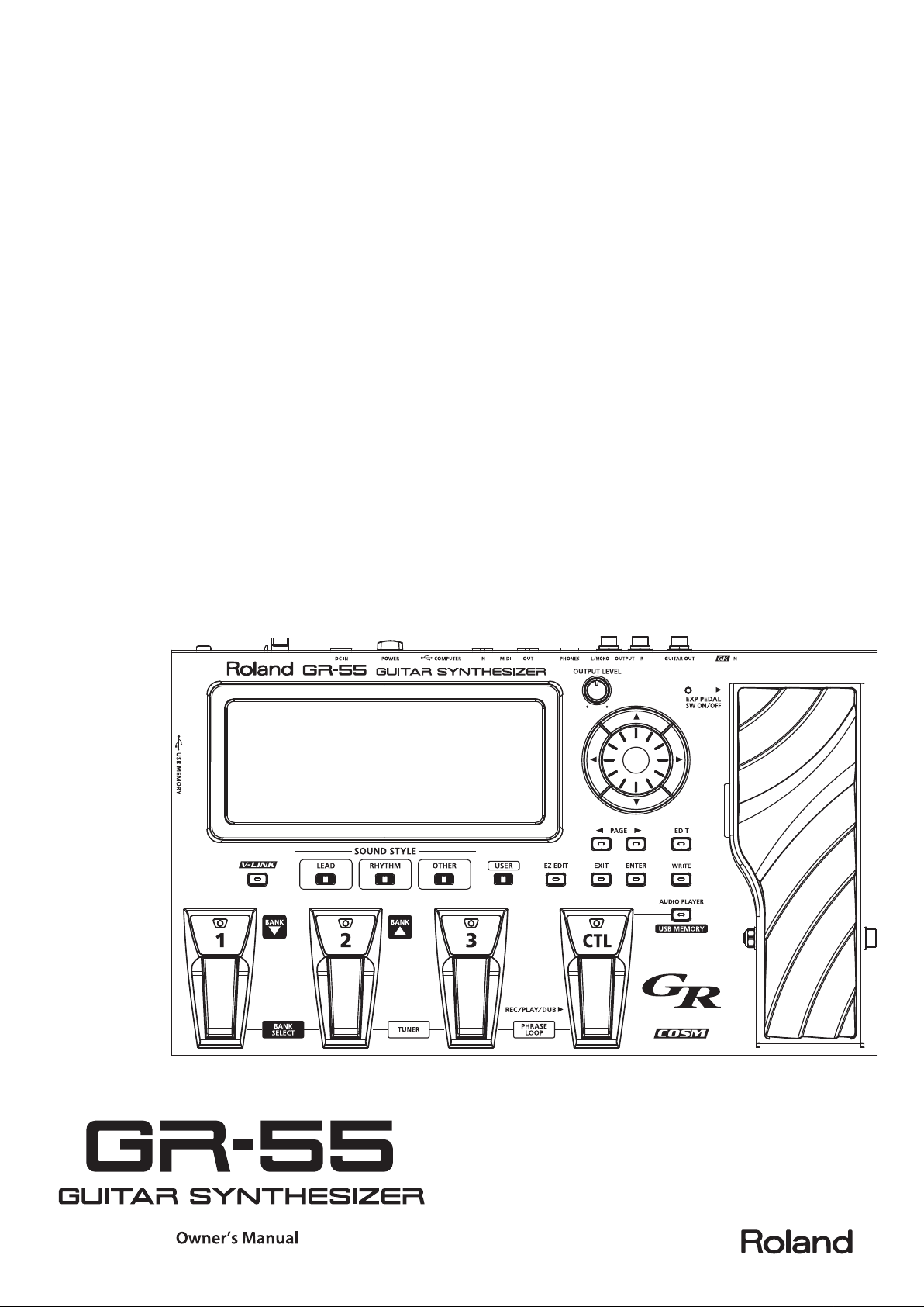
Page 1
Page 2
Contents
USING THE UNIT SAFELY . . . . . . . . . . . . . . . . . . . . . . . . . . . . . 4
IMPORTANT NOTES . . . . . . . . . . . . . . . . . . . . . . . . . . . . . . . . . 5
Main Features . . . . . . . . . . . . . . . . . . . . . . . . . . . . . . . . . . . . . . 6
Settings 7
Preparations for Using the GR-55 . . . . . . . . . . . . . . . . . . . . 8
Connections . . . . . . . . . . . . . . . . . . . . . . . . . . . . . . . . . . . . . . . . . . . . . . . . . . . . . 8
Turning the Power On/O . . . . . . . . . . . . . . . . . . . . . . . . . . . . . . . . . . . . . . . . 8
Selecting Guitar or Bass (GUITAR<->BASS). . . . . . . . . . . . . . . . . . . . . . . . . 9
Adjusting the Pickups (GK SETTING). . . . . . . . . . . . . . . . . . . . . . . . . . . . . . . 9
Adjusting Your Guitar Pickup . . . . . . . . . . . . . . . . . . . . . . . . . . . . . .10
Adjusting Your Bass Pickup . . . . . . . . . . . . . . . . . . . . . . . . . . . . . . . . 11
Specifying the Output System (OUTPUT SELECT) . . . . . . . . . . . . . . . . . 12
Tuning Your Instrument (the Tuner Function) . . . . . . . . . . . . . . . . . . . . .13
Quick Guide 15
Selecting and Playing Sounds . . . . . . . . . . . . . . . . . . . . . . 16
Adjusting the Output Level . . . . . . . . . . . . . . . . . . . . . . . . . . . . . . . . . . . . . .16
Selecting a Sound (Patch) . . . . . . . . . . . . . . . . . . . . . . . . . . . . . . . . . . . . . . .16
Playing Your Guitar . . . . . . . . . . . . . . . . . . . . . . . . . . . . . . . . . . . . . . . . . . . . . .17
Creating an Original Sound . . . . . . . . . . . . . . . . . . . . . . . . . . . . . . . . . . . . . .18
Using the EZ EDIT Function to Create a Sound . . . . . . . . . . . . . .18
Saving the Sound You Created . . . . . . . . . . . . . . . . . . . . . . . . . . . . .18
Reference 19
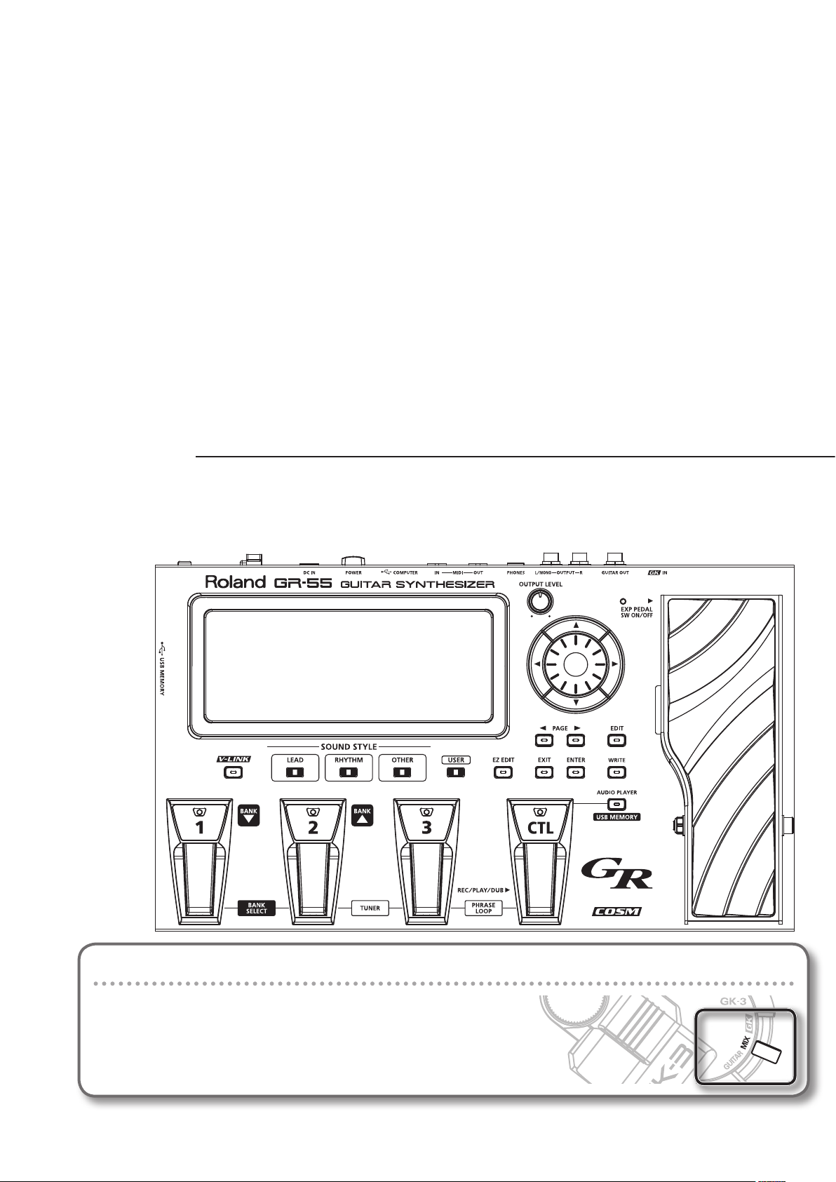
Panel Descriptions . . . . . . . . . . . . . . . . . . . . . . . . . . . . . . . . . 20
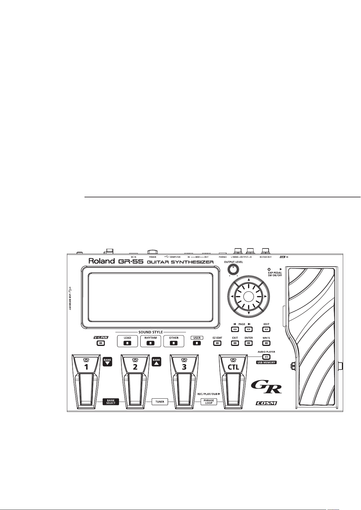
Front Panel . . . . . . . . . . . . . . . . . . . . . . . . . . . . . . . . . . . . . . . . . . . . . . . . . . . . . . 20
About the Top Screen . . . . . . . . . . . . . . . . . . . . . . . . . . . . . . . . . . . . .20
About the EDIT Screen . . . . . . . . . . . . . . . . . . . . . . . . . . . . . . . . . . . . . 20
Rear Panel . . . . . . . . . . . . . . . . . . . . . . . . . . . . . . . . . . . . . . . . . . . . . . . . . . . . . .21
Side Panel . . . . . . . . . . . . . . . . . . . . . . . . . . . . . . . . . . . . . . . . . . . . . . . . . . . . . . . 21
How the GR-55 Works . . . . . . . . . . . . . . . . . . . . . . . . . . . . . . 22
Editing the Tones (TONE) . . . . . . . . . . . . . . . . . . . . . . . . . . . 23
Changing the Tone . . . . . . . . . . . . . . . . . . . . . . . . . . . . . . . . . . . . . . . . . . . . . .23
Tone Category . . . . . . . . . . . . . . . . . . . . . . . . . . . . . . . . . . . . . . . . . . . .23
Editing the Tone . . . . . . . . . . . . . . . . . . . . . . . . . . . . . . . . . . . . . . . . . . . . . . . . .24
Editing a Tone (Detailed Settings) . . . . . . . . . . . . . . . . . . . . . . . . . . . . . . . .24
Parameter List (PCM TONE 1/PCM TONE 2) . . . . . . . . . . . . . . . . . . . . . . .25
Parameter List (MODELING TONE) . . . . . . . . . . . . . . . . . . . . . . . . . . . . . . . .29
Eect Settings (EFFECT) . . . . . . . . . . . . . . . . . . . . . . . . . . . . 38
Switching the Eect Type . . . . . . . . . . . . . . . . . . . . . . . . . . . . . . . . . . . . . . . . 38
Editing the Eects . . . . . . . . . . . . . . . . . . . . . . . . . . . . . . . . . . . . . . . . . . . . . . .39
Eect Editing (Detailed Settings) . . . . . . . . . . . . . . . . . . . . . . . . . . . . . . . . .39
Changing the Structure/Specifying the Connection Destination . . 40
Parameter List (EFFECT) . . . . . . . . . . . . . . . . . . . . . . . . . . . . . . . . . . . . . . . . .41
AMP . . . . . . . . . . . . . . . . . . . . . . . . . . . . . . . . . . . . . . . . . . . . . . . . . . . . . . 41
MOD . . . . . . . . . . . . . . . . . . . . . . . . . . . . . . . . . . . . . . . . . . . . . . . . . . . . . .42
MFX . . . . . . . . . . . . . . . . . . . . . . . . . . . . . . . . . . . . . . . . . . . . . . . . . . . . . .45
DELAY . . . . . . . . . . . . . . . . . . . . . . . . . . . . . . . . . . . . . . . . . . . . . . . . . . . . 52
REVERB . . . . . . . . . . . . . . . . . . . . . . . . . . . . . . . . . . . . . . . . . . . . . . . . . . . 52
CHORUS . . . . . . . . . . . . . . . . . . . . . . . . . . . . . . . . . . . . . . . . . . . . . . . . . .53
EQ . . . . . . . . . . . . . . . . . . . . . . . . . . . . . . . . . . . . . . . . . . . . . . . . . . . . . . . .53
Patch Settings (MASTER) . . . . . . . . . . . . . . . . . . . . . . . . . . . 54
Pedal and GK Control Settings (PEDAL/GK CTL) . . . . . . . . . . . . . . . . . . .54
Controller Settings (ASSIGN) . . . . . . . . . . . . . . . . . . . . . . . . . . . . . . . . . . . . .54
Patch Tempo Setting (PATCH TEMPO) . . . . . . . . . . . . . . . . . . . . . . . . . . . .54
GK Pickup Settings for Each Patch (GK SET) . . . . . . . . . . . . . . . . . . . . . . .54
GUITAR OUT Jack Settings (GUITAR OUT) . . . . . . . . . . . . . . . . . . . . . . . . .54
Changing the Tuning of Each String (ALT-TUNING) . . . . . . . . . . . . . . . .54
V-LINK Settings (V-LINK) . . . . . . . . . . . . . . . . . . . . . . . . . . . . . . . . . . . . . . . . .54
Parameter List (MASTER) . . . . . . . . . . . . . . . . . . . . . . . . . . . . . . . . . . . . . . . . . 55
PEDAL/GK CTL . . . . . . . . . . . . . . . . . . . . . . . . . . . . . . . . . . . . . . . . . . . .55
ASSIGN . . . . . . . . . . . . . . . . . . . . . . . . . . . . . . . . . . . . . . . . . . . . . . . . . . .57
PATCH TEMPO . . . . . . . . . . . . . . . . . . . . . . . . . . . . . . . . . . . . . . . . . . . . .58
GK SET . . . . . . . . . . . . . . . . . . . . . . . . . . . . . . . . . . . . . . . . . . . . . . . . . . . .58
GUITAR OUT . . . . . . . . . . . . . . . . . . . . . . . . . . . . . . . . . . . . . . . . . . . . . . . 59
ALT-TUNING . . . . . . . . . . . . . . . . . . . . . . . . . . . . . . . . . . . . . . . . . . . . . . .59
V-LINK . . . . . . . . . . . . . . . . . . . . . . . . . . . . . . . . . . . . . . . . . . . . . . . . . . . . 59
Before using this unit, carefully read the sections entitled: “USING THE UNIT SAFELY” (p.4) and “IMPORTANT NOTES” (p.5). These sections provide
important information concerning the proper operation of the unit. Additionally, in order to feel assured that you have gained a good grasp of every
feature provided by your new unit, Owner’s manual should be read in its entirety. The manual should be saved and kept on hand as a convenient
reference.
Copyright © 2011 ROLAND CORPORATION All rights reserved. No part of this publication may be reproduced in any form without the
written permission of ROLAND CORPORATION.
Roland and COSM are registered trademarks of Roland Corporation in the United States and/or other countries.
2
Page 3

Contents
Saving a Patch (PATCH WRITE) . . . . . . . . . . . . . . . . . . . . . . 60
Saving a Patch (PATCH WRITE) . . . . . . . . . . . . . . . . . . . . . . . . . . . . . . . . . . .60
Renaming a Patch . . . . . . . . . . . . . . . . . . . . . . . . . . . . . . . . . . . . . . . . .60
Changing the Order of Patches (PATCH EXCHANGE) . . . . . . . . . . . . . . 60
Initializing the Settings of a Patch (PATCH INITIALIZE) . . . . . . . . . . . . .60
Controller Assignments . . . . . . . . . . . . . . . . . . . . . . . . . . . . 61
Controllers Whose Assignment Can Be Changed . . . . . . . . . . . . . . . . .61
Making a Pedal Have the Same Operation for All Patches . . . 61
Changing the Pedal Assignments for Each Patch . . . . . . . . . . . .61
Specifying the Parameter to be Controlled by the
Controller . . . . . . . . . . . . . . . . . . . . . . . . . . . . . . . . . . . . . . . . . . . . . . . . .62
Using Phrase Loop . . . . . . . . . . . . . . . . . . . . . . . . . . . . . . . . . 64
Using the GR-55 as an Audio Player . . . . . . . . . . . . . . . . . 65
Copying Audio Files From Your Computer to USB Memory . . . . . . . .65
Inserting the USB Memory . . . . . . . . . . . . . . . . . . . . . . . . . . . . . . . . . . . . . . .65
Playing Back Audio . . . . . . . . . . . . . . . . . . . . . . . . . . . . . . . . . . . . . . . . . . . . . . 65
Using the Pedal to Control the Audio Player . . . . . . . . . . . . . . . . . . . . . .65
Connecting External Equipment . . . . . . . . . . . . . . . . . . . . 66
Connecting a Computer via USB . . . . . . . . . . . . . . . . . . . . . . . . . . . . . . . . .66
Connecting the GR-55 to a Computer . . . . . . . . . . . . . . . . . . . . . .66
USB function settings. . . . . . . . . . . . . . . . . . . . . . . . . . . . . . . . . . . . . .66
Connecting the GR-55 to MIDI Devices . . . . . . . . . . . . . . . . . . . . . . . . . . .67
About the MIDI Connectors . . . . . . . . . . . . . . . . . . . . . . . . . . . . . . . .67
MIDI Settings . . . . . . . . . . . . . . . . . . . . . . . . . . . . . . . . . . . . . . . . . . . . . .67
Connecting the GR-55 to V-LINK Devices (V-LINK) . . . . . . . . . . . . . . . .68
Turning V-LINK On/O . . . . . . . . . . . . . . . . . . . . . . . . . . . . . . . . . . . . . 68
V-LINK Settings . . . . . . . . . . . . . . . . . . . . . . . . . . . . . . . . . . . . . . . . . . . .68
Parameter List (SYSTEM) . . . . . . . . . . . . . . . . . . . . . . . . . . . . . . . . . . . . . . . . . 74
GK SETTING . . . . . . . . . . . . . . . . . . . . . . . . . . . . . . . . . . . . . . . . . . . . . . . 74
OUTPUT SELECT . . . . . . . . . . . . . . . . . . . . . . . . . . . . . . . . . . . . . . . . . . . 75
PEDAL/GK CTL . . . . . . . . . . . . . . . . . . . . . . . . . . . . . . . . . . . . . . . . . . . .76
MIDI/USB . . . . . . . . . . . . . . . . . . . . . . . . . . . . . . . . . . . . . . . . . . . . . . . . .79
OTHER . . . . . . . . . . . . . . . . . . . . . . . . . . . . . . . . . . . . . . . . . . . . . . . . . . . .80
BACKUP/INITIALIZE . . . . . . . . . . . . . . . . . . . . . . . . . . . . . . . . . . . . . . . . 80
Appendix 81
GR-55 Patch List . . . . . . . . . . . . . . . . . . . . . . . . . . . . . . . . . . . 82
GUITAR MODE . . . . . . . . . . . . . . . . . . . . . . . . . . . . . . . . . . . . . . . . . . . . . 82
BASS MODE . . . . . . . . . . . . . . . . . . . . . . . . . . . . . . . . . . . . . . . . . . . . . . .88
Troubleshooting . . . . . . . . . . . . . . . . . . . . . . . . . . . . . . . . . . . 90
Error Messages . . . . . . . . . . . . . . . . . . . . . . . . . . . . . . . . . . . . 92
Signal Flow . . . . . . . . . . . . . . . . . . . . . . . . . . . . . . . . . . . . . . . . 93
MIDI Implementation Chart . . . . . . . . . . . . . . . . . . . . . . . . 94
Main Specications . . . . . . . . . . . . . . . . . . . . . . . . . . . . . . . . 95
Index . . . . . . . . . . . . . . . . . . . . . . . . . . . . . . . . . . . . . . . . . . . . . 96
Settings for the Entire GR-55 (SYSTEM) . . . . . . . . . . . . . . 69
Setting the GK Pickups (GK SETTING) . . . . . . . . . . . . . . . . . . . . . . . . . . . . . 69
Switching GK Sets . . . . . . . . . . . . . . . . . . . . . . . . . . . . . . . . . . . . . . . . .70
Renaming a GK Set . . . . . . . . . . . . . . . . . . . . . . . . . . . . . . . . . . . . . . . .70
Specifying the Output Device (OUTPUT SELECT) . . . . . . . . . . . . . . . . . 70
Pedal and GK Control Settings (PEDAL/GK CTL) . . . . . . . . . . . . . . . . . . . 70
MIDI and USB Settings (MIDI/USB) . . . . . . . . . . . . . . . . . . . . . . . . . . . . . . . 70
GUITAR OUT Jack Settings (GUITAR OUT) . . . . . . . . . . . . . . . . . . . . . . . . .70
Always Outputting the Normal Pickup Sound from the
GUITAR OUT Jack for All Patches . . . . . . . . . . . . . . . . . . . . . . . . . . . 70
Always Outputting the Modeling Tone Sound from the
GUITAR OUT Jack for All Patches . . . . . . . . . . . . . . . . . . . . . . . . . . . 70
Changing the Output Sound from the GUITAR OUT Jack for
Each Patch . . . . . . . . . . . . . . . . . . . . . . . . . . . . . . . . . . . . . . . . . . . . . . . .71
Tuning Your Guitar (TUNER) . . . . . . . . . . . . . . . . . . . . . . . . . . . . . . . . . . . . . . 71
Adjusting the Display Contrast (LCD) . . . . . . . . . . . . . . . . . . . . . . . . . . . . . 71
Auto Power O Settings (POWER) . . . . . . . . . . . . . . . . . . . . . . . . . . . . . . . . 71
Switching Between Guitar and Bass (GUITAR<->BASS) . . . . . . . . . . . .71
Saving GR-55 Settings to USB Memory (BACKUP) . . . . . . . . . . . . . . . . .72
Restoring GR-55 Settings from USB Memory (RESTORE) . . . . .72
Adjusting the Pedal Sensitivity (CALIB) . . . . . . . . . . . . . . . . . . . . . . . . . .73
Restoring the Factory Settings (FACTORY RESET) . . . . . . . . . . . . . . . . . 73
3
Page 4
USING THE UNIT SAFELY
About WARNING and CAUTION Notices
Used for instructions intended to alert the
user to the risk of death or severe injury
should the unit be used improperly.
Used for instructions intended to alert the
user to the risk of injury or material
damage should the unit be used
improperly.
* Material damage refers to damage or
other adverse effects caused with
respect to the home and all its
furnishings, as well to domestic animals
or pets.
ALWAYS OBSERVE THE FOLLOWING
WARNING
Do not attempt to repair the unit, or replace parts within it (except when
this manual provides specic instructions directing you to do so). Refer all
servicing to your retailer, the nearest Roland Service Center, or an authorized Roland distributor, as listed on the “Information” page.
Never install the unit in any of the following locations.
• Subject to temperature extremes (e.g., direct sunlight in an enclosed
vehicle, near a heating duct, on top of heat-generating equipment); or are
• Damp (e.g., baths, washrooms, on wet oors); or are
• Exposed to steam or smoke; or are
• Subject to salt exposure; or are
• Humid; or are
• Exposed to rain; or are
• Dusty or sandy; or are
• Subject to high levels of vibration and shakiness.
Make sure you always have the unit placed so it is level and sure to remain
stable. Never place it on stands that could wobble, or on inclined surfaces.
Be sure to use only the AC adaptor supplied with the unit. Also, make sure
the line voltage at the installation matches the input voltage specied on
the AC adaptor’s body. Other AC adaptors may use a dierent polarity, or
be designed for a dierent voltage, so their use could result in damage,
malfunction, or electric shock.
Use only the attached power-supply cord. Also, the supplied power cord
must not be used with any other device.
Do not excessively twist or bend the power cord, nor place heavy objects
on it. Doing so can damage the cord, producing severed elements and
short circuits. Damaged cords are re and shock hazards!
This unit, either alone or in combination with an amplier and headphones
or speakers, may be capable of producing sound levels that could cause
permanent hearing loss. Do not operate for a long period of time at a high
volume level, or at a level that is uncomfortable. If you experience any
hearing loss or ringing in the ears, you should immediately stop using the
unit, and consult an audiologist.
Do not place containers containing liquid on this product. Never allow
foreign objects (e.g., ammable objects, coins, wires) or liquids (e.g., water
or juice) to enter this product. Doing so may cause short circuits, faulty
operation, or other malfunctions.
Immediately turn the power o, remove the AC adaptor from the outlet,
and request servicing by your retailer, the nearest Roland Service Center, or
an authorized Roland distributor, as listed on the “Information” page when:
• The AC adaptor, the power-supply cord, or the plug has been damaged;
or
• If smoke or unusual odor occurs
• Objects have fallen into, or liquid has been spilled onto the unit; or
• The unit has been exposed to rain (or otherwise has become wet); or
• The unit does not appear to operate normally or exhibits a marked
change in performance.
About the Symbols
The symbol alerts the user to important instructions or
warnings. The specific meaning of the symbol is
determined by the design contained within the triangle. In
the case of the symbol at left, it is used for general
cautions, warnings, or alerts to danger.
The symbol alerts the user to items that must never be
carried out (are forbidden). The specific thing that must
not be done is indicated by the design contained within
the circle. In the case of the symbol at left, it means that
the unit must never be disassembled.
The symbol alerts the user to things that must be
carried out. The specific thing that must be done is
indicated by the design contained within the circle. In the
case of the symbol at left, it means that the power-cord
plug must be unplugged from the outlet.
WARNING
In households with small children, an adult should provide supervision
until the child is capable of following all the rules essential for the safe
operation of the unit.
Protect the unit from strong impact. (Do not drop it!)
Do not force the unit’s power-supply cord to share an outlet with an
unreasonable number of other devices. Be especially careful when using
extension cords–the total power used by all devices you have connected
to the extension cord’s outlet must never exceed the power rating (watts/
amperes) for the extension cord. Excessive loads can cause the insulation
on the cord to heat up and eventually melt through.
Before using the unit in a foreign country, consult with your retailer, the
nearest Roland Service Center, or an authorized Roland distributor, as listed
on the “Information” page.
CAUTION
The unit and the AC adaptor should be located so their location or position
does not interfere with their proper ventilation.
Always grasp only the plug on the AC adaptor cord when plugging into, or
unplugging from, an outlet or this unit.
At regular intervals, you should unplug the AC adaptor and clean it by
using a dry cloth to wipe all dust and other accumulations away from its
prongs. Also, disconnect the power plug from the power outlet whenever
the unit is to remain unused for an extended period of time. Any accumulation of dust between the power plug and the power outlet can result in
poor insulation and lead to re.
Try to prevent cords and cables from becoming entangled. Also, all cords
and cables should be placed so they are out of the reach of children.
Never climb on top of, nor place heavy objects on the unit.
Never handle the AC adaptor or its plugs with wet hands when plugging
into, or unplugging from, an outlet or this unit.
Before moving the unit, disconnect the AC adaptor and all cords coming
from external devices.
Before cleaning the unit, turn o the power and unplug the AC adaptor
from the outlet (p.8).
Whenever you suspect the possibility of lightning in your area, disconnect
the AC adaptor from the outlet.
Keep the ground terminal screw and/or USB connector cap you may
remove in a safe place out of children’s reach, so there is no chance of them
being swallowed accidentally.
4
Page 5
IMPORTANT NOTES
Power Supply
• Do not connect this unit to same electrical outlet
that is being used by an electrical appliance that
is controlled by an inverter (such as a refrigerator,
washing machine, microwave oven, or air conditioner),
or that contains a motor. Depending on the way in
which the electrical appliance is used, power supply
noise may cause this unit to malfunction or may
produce audible noise. If it is not practical to use a
separate electrical outlet, connect a power supply
noise lter between this unit and the electrical outlet.
• The AC adaptor will begin to generate heat after long
hours of consecutive use. This is normal, and is not a
cause for concern.
• Before connecting this unit to other devices, turn
o the power to all units. This will help prevent
malfunctions and/or damage to speakers or other
devices.
Placement
• Using the unit near power ampliers (or other
equipment containing large power transformers) may
induce hum. To alleviate the problem, change the
orientation of this unit; or move it farther away from
the source of interference.
• This device may interfere with radio and television
reception. Do not use this device in the vicinity of such
receivers.
• Noise may be produced if wireless communications
devices, such as cell phones, are operated in the
vicinity of this unit. Such noise could occur when
receiving or initiating a call, or while conversing.
Should you experience such problems, you should
relocate such wireless devices so they are at a greater
distance from this unit, or switch them o.
• Do not expose the unit to direct sunlight, place it near
devices that radiate heat, leave it inside an enclosed
vehicle, or otherwise subject it to temperature
extremes. Excessive heat can deform or discolor the
unit.
• When moved from one location to another where the
temperature and/or humidity is very dierent, water
droplets (condensation) may form inside the unit.
Damage or malfunction may result if you attempt to
use the unit in this condition. Therefore, before using
the unit, you must allow it to stand for several hours,
until the condensation has completely evaporated.
• Depending on the material and temperature of the
surface on which you place the unit, its rubber feet
may discolor or mar the surface.
You can place a piece of felt or cloth under the rubber
feet to prevent this from happening. If you do so,
please make sure that the unit will not slip or move
accidentally.
• Do not put anything that contains water on this unit.
Also, avoid the use of insecticides, perfumes, alcohol,
nail polish, spray cans, etc., near the unit. Swiftly wipe
away any liquid that spills on the unit using a dry, soft
cloth.
Maintenance
• For everyday cleaning wipe the unit with a soft,
dry cloth or one that has been slightly dampened
with water. To remove stubborn dirt, use a cloth
impregnated with a mild, non-abrasive detergent.
Afterwards, be sure to wipe the unit thoroughly with a
soft, dry cloth.
• Never use benzine, thinners, alcohol or solvents of any
kind, to avoid the possibility of discoloration and/or
deformation.
Repairs and Data
• Please be aware that all data contained in the unit’s
memory may be lost when the unit is sent for repairs.
Important data should always be backed up on USB
memories or written down on paper (when possible).
During repairs, due care is taken to avoid the loss of
data. However, in certain cases (such as when circuitry
related to memory itself is out of order), we regret that
it may not be possible to restore the data, and Roland
assumes no liability concerning such loss of data.
Using External Memories
• Carefully insert the USB memories all the way in—until
it is rmly in place.
• Never touch the terminals of the USB memories. Also,
avoid getting the terminals dirty.
• USB memories are constructed using precision
components; handle the cards carefully, paying
particular note to the following.
• To prevent damage to the cards from static
electricity, be sure to discharge any static electricity
from your own body before handling the cards.
• Do not touch or allow metal to come into contact
with the contact portion of the cards.
• Do not bend, drop, or subject cards to strong shock
or vibration.
• Do not keep cards in direct sunlight, in closed
vehicles, or other such locations.
• Do not allow cards to become wet.
• Do not disassemble or modify the cards.
Additional Precautions
• Please be aware that the contents of memory can
be irretrievably lost as a result of a malfunction,
or the improper operation of the unit. To protect
yourself against the risk of loosing important data,
we recommend that you periodically save a backup
copy of important data you have stored in the unit’s
memory on USB memories.
• Unfortunately, it may be impossible to restore the
contents of data that was stored in the unit’s memory
or on USB memories once it has been lost. Roland
Corporation assumes no liability concerning such loss
of data.
• Use a reasonable amount of care when using the unit’s
buttons, sliders, or other controls; and when using
its jacks and connectors. Rough handling can lead to
malfunctions.
• Never strike or apply strong pressure to the display.
• When connecting / disconnecting all cables, grasp the
connector itself—never pull on the cable. This way
you will avoid causing shorts, or damage to the cable’s
internal elements.
• When you operate the expression pedal, please be
careful not to get your ngers pinched between the
movable part and the panel.
In households with small children, an adult should
provide supervision until the child is capable of
following all the rules essential for the safe operation
of the unit.
• To avoid disturbing your neighbors, try to keep the
unit’s volume at reasonable levels. You may prefer to
use headphones, so you do not need to be concerned
about those around you.
• When you need to transport the unit, package it in the
box (including padding) that it came in, if possible.
Otherwise, you will need to use equivalent packaging
materials.
• The explanations in this manual include illustrations
that depict what should typically be shown by the
display. Note, however, that your unit may incorporate
a newer, enhanced version of the system (e.g., includes
newer sounds), so what you actually see in the display
may not always match what appears in the manual.
• Microsoft and Windows are registered trademarks of
Microsoft Corporation.
• The screen shots in this document are used in
compliance with the guidelines of the Microsoft
Corporation.
• Windows® is known ocially as: “Microsoft® Windows®
operating system.”
• Apple and Macintosh are registered trademarks of
Apple Inc.
• Mac OS is a trademark of Apple Inc.
• MMP (Moore Microprocessor Portfolio) refers to a
patent portfolio concerned with microprocessor
architecture, which was developed by Technology
Properties Limited (TPL). Roland has licensed this
technology from the TPL Group.
• All product names mentioned in this document
are trademarks or registered trademarks of their
respective owners.
5
Page 6
Main Features
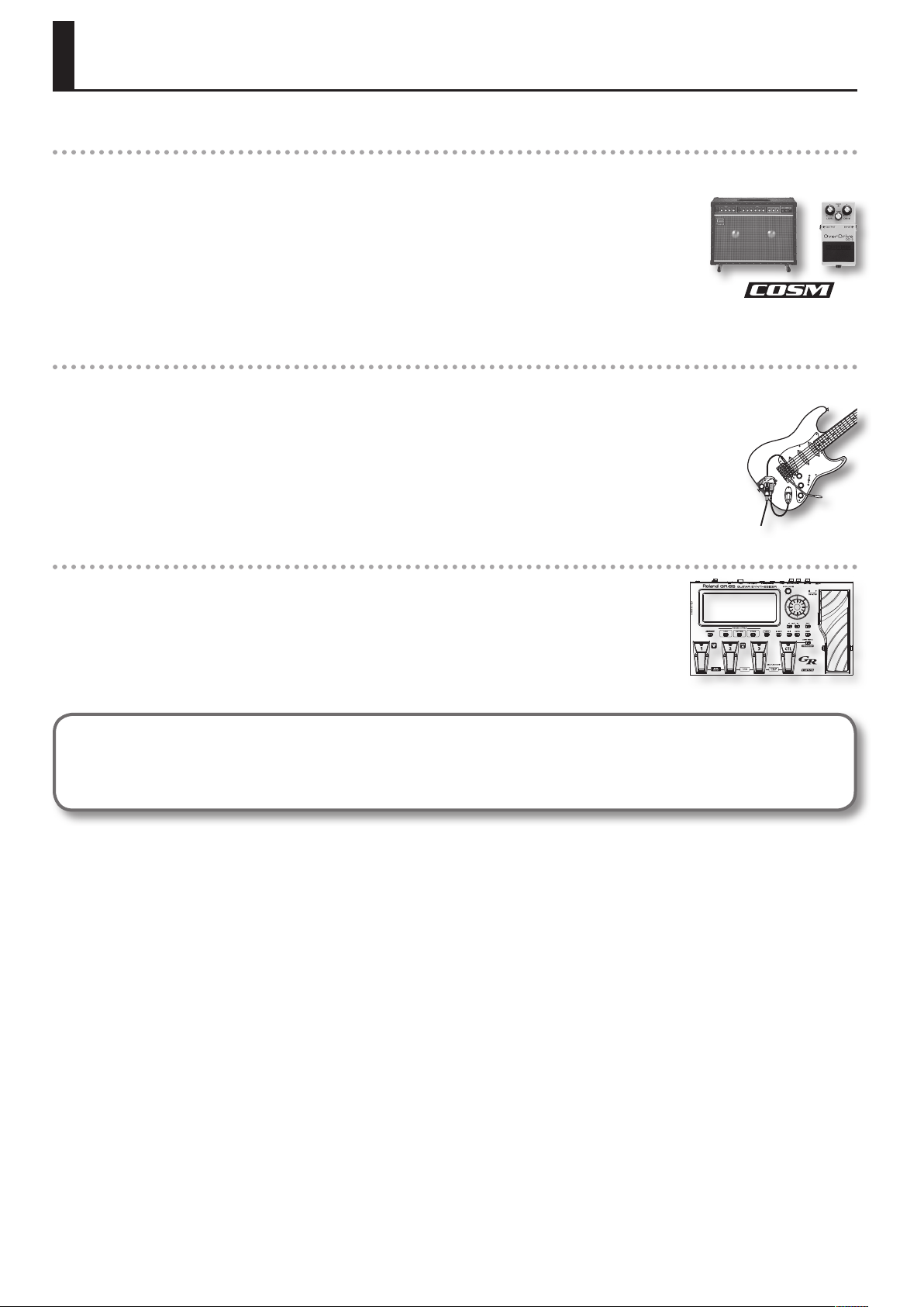
Sound: Sophisticated fusion of a PCM synthesizer and COSM modeling sound generator
Sounds produced by a high-quality PCM synthesizer and a realistic COSM modeling sound generator can be freely
combined to take advantage of each method’s unique characteristics.
You can intuitively create new sound combinations with a high degree of freedom. For example, you could create a
new lead guitar sound that’s based on a standard distorted guitar combined with a synth lead or organ. Alternatively,
you might layer a ute or a synth bell sound with an acoustic guitar to create fantastic new tones.
COSM amps and various eects units are provided independently, allowing you to create an incredible variety
ranging, from raw guitar amp sounds to tricky noise sounds.
Expressiveness: Newly developed guitar pitch detection technology
The independent pickup signal from each of the six strings is analyzed at high speed by a newly developed
algorithm, ensuring quick and accurate response from the sound generator.
In addition, your picking position as well as the dierences between notes played with a pick or with your ngers are
also detected and transmitted to the sound generator, giving the GR-55 a range of performance expression that’s
much broader and more natural than any previous guitar synthesizer.
Easy use: Use SOUND STYLE to select a sound, and use EZ EDIT to edit it
The three SOUND STYLE buttons “LEAD,” “RHYTHM,” and “OTHER” provide performance-ready sounds in a wide range
of musical styles. A large-screen LCD ensures excellent visibility at your feet.
Press the [EZ EDIT] button to make easy graphical adjustments to the sound; this is a great convenience especially
when playing live.
What is the COSM?
Technology that simulates existing physical structures, materials, and the like using dierent, virtual means is called “modeling technology.”
COSM (Composite Object Sound Modeling) is a technical innovation from Roland that combines a number of such sound-modeling
technologies to create new and unique sounds.
6
Page 7
Settings
This chapter explains how to make the necessary settings when using the GR-55 for the rst time.
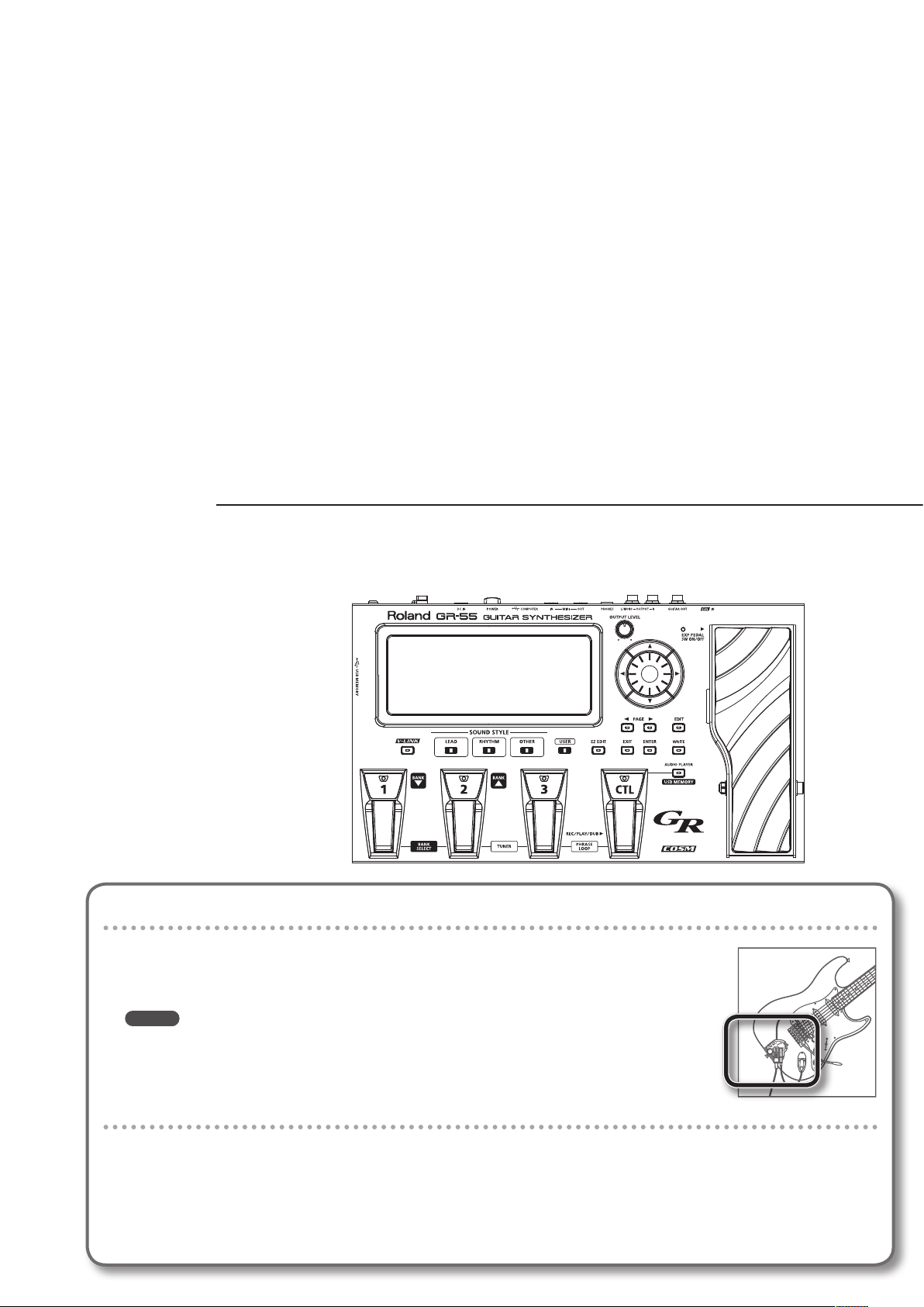
First, get your guitar/bass ready
• In order to use the GR-55, you’ll need a guitar or bass equipped with a divided pickup (GK pickup), which
outputs a separate signal for each string.
You can use GK pickups such as the Roland GK-3 or GK-3B.
• For details on how to install a GK pickup, refer to the owner’s manual that came with your GK pickup.
MEMO
• Be aware that string buzz due to a warped neck or worn frets, or faulty octave adjustment, can cause
problems such as wrong notes being produced.
• This unit does not support 7-string guitars/basses or other non-standard guitars/basses.
Check the Web for details about installing GK pickups
• On the Roland website, the “GK-3/3B Installation Tips” page provides an explanation and photos on how to
attach a GK pickup. Be sure to take a look!
http://www.roland.com/GK/
Page 8
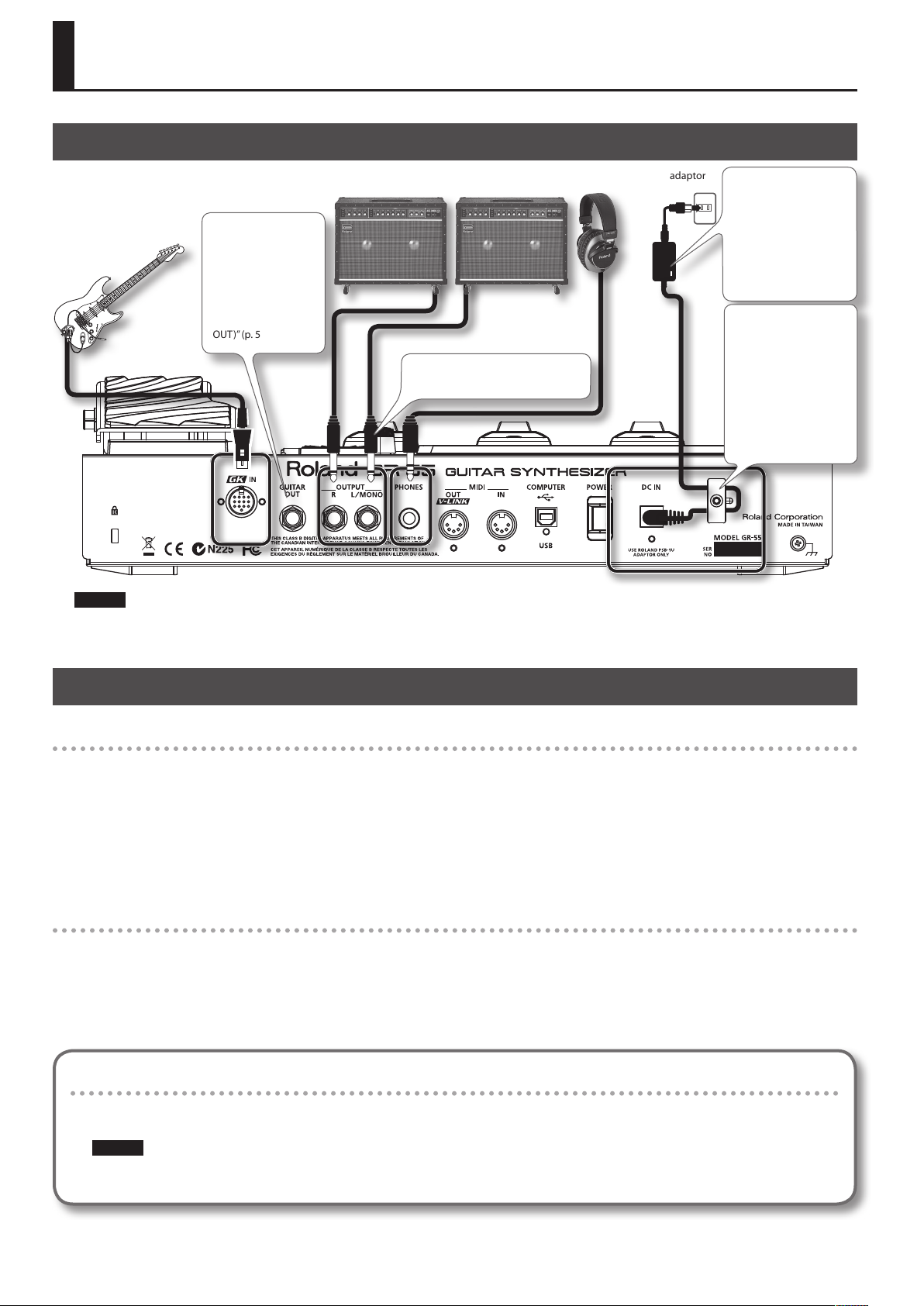
Preparations for Using the GR-55
Connections
Guitar equipped with a GK-3/
GK-2A, bass equipped with a
GK-3B/GK-2B, or a commercially
available GK-ready guitar or
bass
The GUITAR OUT jack
outputs the sound of
the normal pickups
and the sound of the
modeling tone (p.22).
For details, refer to
“GUITAR OUT Jack
Settings (GUITAR
OUT)” (p.54).
Amp or PA (line)
If you’re using monaural output,
connect only to the L/MONO jack.
Headphones AC adaptor
Place the AC adaptor so
the side with the indicator
(see illustration) faces
upwards and the side
with textual information
faces downwards.
The indicator will light
when you plug the AC
adaptor into an AC outlet.
To prevent the
inadvertent disruption
of power to your unit
(should the plug be
pulled out accidentally),
and to avoid applying
undue stress to the AC
adaptor jack, anchor the
power cord using the
cord hook, as shown in
the illustration.
NOTE!
• To prevent malfunction and/or damage to speakers or other devices, always turn down the volume, and turn o the power on all devices before
making any connections.
• Switch on the power to all of your equipment before you raise the volume of the amp.
Turning the Power On/O
Turning the power on
Once the connections have been completed, turn on power to your various devices in the order specied. By turning on devices in the wrong order,
you risk causing malfunction and/or damage to speakers and other devices.
* Always make sure to have the volume level turned down before switching on power. Even with the volume all the way down, you may still hear
some sound when the power is switched on, but this is normal, and does not indicate a malfunction.
* This unit is equipped with a protection circuit. A brief interval (a few seconds) after power up is required before the unit will operate normally.
1. Press the GR-55’s [POWER] switch to turn the power on.
2. Turn on the power of your amp.
Turning the power o
1. Check the following before you turn the power o.
• Have you minimized the volume on the connected equipment?
• Have you saved the data (settings, sounds, etc.) that you want to keep?
2. Turn o the power of your guitar amp or other connected equipment.
3. Press the GR-55’s [POWER] switch to turn the power o.
If you don’t want the power to turn o automatically, turn the “AUTO POWER OFF” setting o!
With the factory settings, the GR-55’s power will automatically be switched o 10 hours after you stop playing or operating the unit.
If you want to have the power remain on all the time, change the “AUTO POWER OFF” setting to “OFF” as described on p.71.
NOTE!
The settings you were editing will be lost when the power is turned o. If you want to keep your settings, you must save your settings before
turning the power o.
8
Page 9
Preparations for Using the GR-55
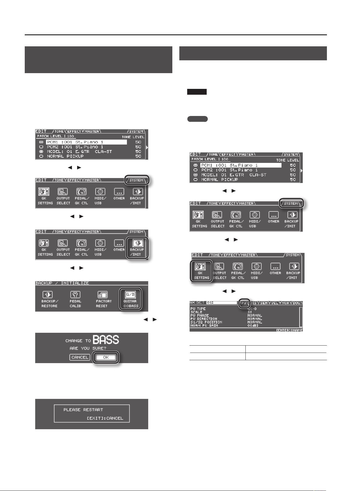
Selecting Guitar or Bass (GUITAR<->BASS)
Before you use the GR-55, you must make a mode setting that species
whether you’re using it with a guitar or with a bass.
* With the factory settings, this is set to “GUITAR.”
* If BASS MODE is selected, some parameter names are displayed
dierently than in GUITAR MODE.
(Example) String numbers “1, 2, 3, 4, 5, 6” --> “H, 1, 2, 3, 4, L.”
1. Press the [EDIT] button to access the EDIT screen.
2. Use the PAGE [ ] [ ] buttons to select the SYSTEM tab.
3. Use the cursor [ ] [ ] buttons to select the BACKUP/INIT
icon, and press the [ENTER] button.
Adjusting the Pickups (GK SETTING)
To ensure that the GR-55 is in the best possible playing condition,
please make the appropriate adjustments for the divided pickup (GK
settings). Making these settings will ensure that the GR-55 is operating
optimally.
NOTE!
GK settings are extremely important in order to play the GR-55 with
the best possible sound. You must be sure to make these settings
correctly.
MEMO
If you connect dierent guitars to the GR-55 at dierent times, you
can individually save settings for each guitar. For details, refer to
“Setting the GK Pickups (GK SETTING)” (p.69).
1. Press the [EDIT] button to access the EDIT screen.
2. Use the PAGE [ ] [ ] buttons to access the SYSTEM tab.
4. Use the cursor [ ] [ ] buttons to select the GUITAR<->BASS
icon and press the [ENTER] button.
5. If you want to change the mode, use the cursor [ ] [ ]
buttons to select “OK,” and press the [ENTER] button.
If you decide not to change the mode, choose “CANCEL” and press the
[ENTER] button.
6. When the following screen appears, turn the GR-55’s power
o.
3. Use the cursor [ ] [ ] buttons to select the GK SETTING
icon, and press the [ENTER] button.
4. Use the PAGE [ ] [ ] buttons to select the PU tab.
5. Adjust your pickup.
If you’re using a guitar “Adjusting Your Guitar Pickup” (p.10)
If you’re using a bass “Adjusting Your Bass Pickup” (p.11)
The next time you turn the GR-55’s power on, the screen will indicate
the specied mode (“GUITAR MODE” or “BASS MODE”).
Once you’ve set the mode, the GR-55 will start up in the specied
mode each time it’s powered up.
9
Page 10
Preparations for Using the GR-55
Adjusting Your Guitar Pickup
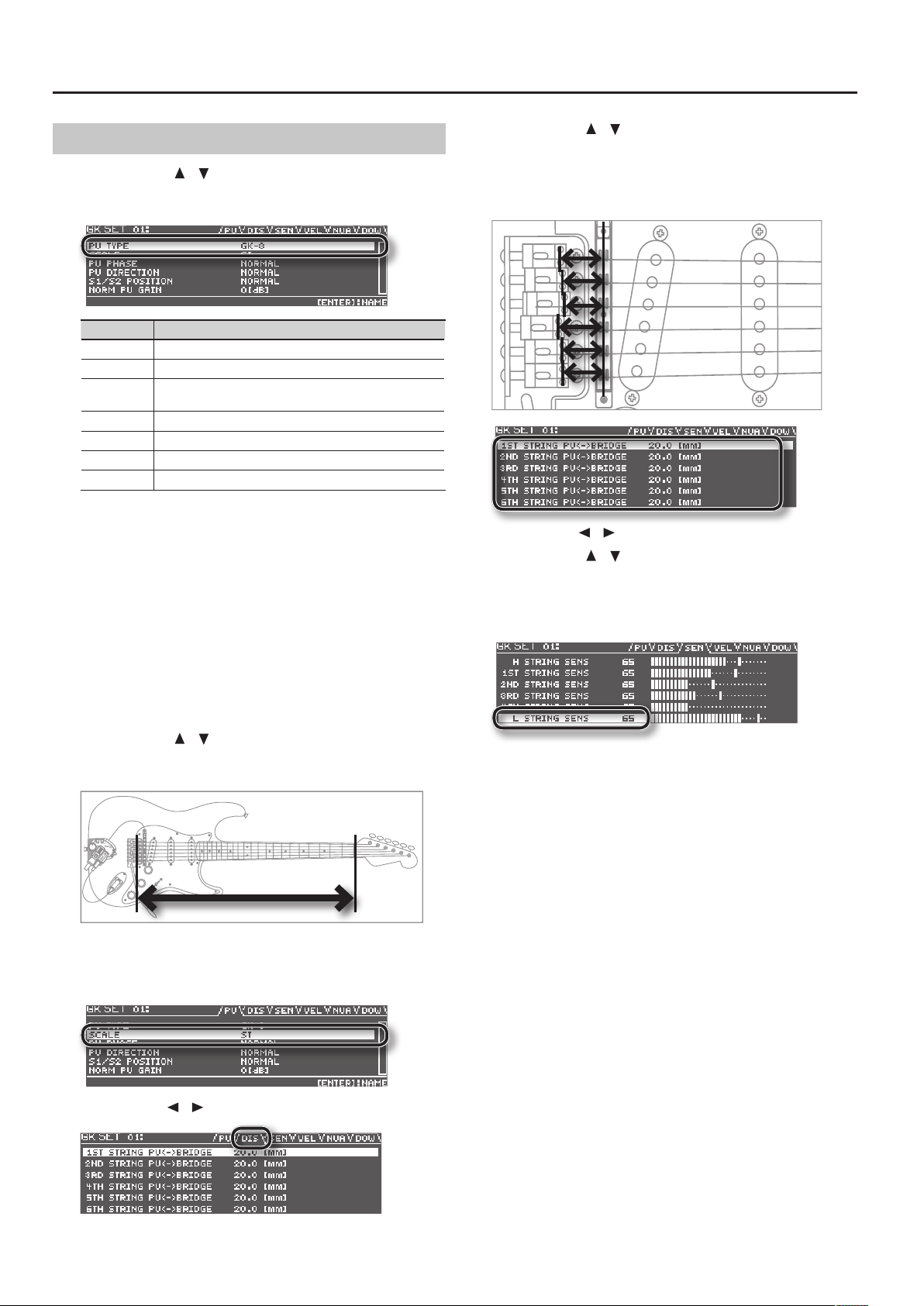
1. Use the cursor [ ] [ ] buttons to move the cursor to “PU
TYPE,” and use the dial to select the type of pickup that’s
installed on your guitar.
Value Description
GK-3 Choose this if you’re using a GK-3.
GK-2A Choose this if you’re using a GK-2A.
PIEZO
PIEZO F This setting is appropriate for a Fishman piezo pickup.
PIEZO G This setting is appropriate for a Graph Tech piezo pickup.
PIEZO L This setting is appropriate for an L.R. Baggs piezo pickup.
PIEZO R This setting is appropriate for an RMC piezo pickup.
A piezo pickup is a type of pickup that is mounted on the bridge of the
guitar, and uses a piezoelectric element to detect the vibrations of the
strings.
If you’re using a guitar equipped with a GK pickup that’s not of the
piezo type, choose “GK-2A.”
* If you’re not sure which piezo type setting is appropriate, try
selecting dierent choices while you play your guitar, and choose
the piezo type that produces the most natural sound. In this case,
the dierence will be easier to notice if you turn o the PCM 1 and 2
tone switches (p.25).
* If you’ve chosen PIEZO, PIEZO F, PIEZO G, PIEZO L, or PIEZO R as the
PU Type setting, you’ll be able to make further adjustments to the
tone quality of the high range and low range (p.75).
2. Use the cursor [ ] [ ] buttons to move the cursor to
“SCALE,” and use the dial to specify your guitar’s scale length
(the distance between the bridge and nut).
Choose the closest value in the range of 500–660 mm.
Choose “ST” (648 mm) for a standard Stratocaster type, or choose “LP”
(628 mm) for a Les Paul type. For details on the other parameters, refer
to “GK SETTING” (p.74).
3. Use the PAGE [ ] [ ] buttons to select the DIS tab.
This setting is appropriate if you’re using a piezo pickup that
has a at response.
4. Use the cursor [ ] [ ] buttons to select each string, and
for each string, specify the distance from the center of the
pickup to the bridge saddle.
* If PU TYPE is set to one of the piezo-type pickups, this setting is not
necessary.
5. Use the PAGE [ ] [ ] buttons to select the SEN tab.
6. Use the cursor [
] [ ] buttons to move the cursor to 6TH
STRING SENS.
Play the 6th string as strongly as you ever expect to play it in actual
performance, and use the dial to adjust the sensitivity as high as
possible without allowing the meter to reach the full-scale position.
* If the level meter reaches the full-scale position, the level is exces-
sive. Lower the sensitivity.
* Depending on the guitar you’re using, the level meter might reach
full-scale even if the sensitivity is at minimum. If this is the case,
adjust the distance between the divided pickup and the string so it’s
somewhat greater than the recommendation.
7. In the same way, adjust the sensitivity for the 5th through
1st strings as well.
8. Check the volume balance of the six strings.
Play each of the strings 6–1 at normal strength; if a string sounds
unusually loud, lower the sensitivity of that string to minimize any
discrepancy in volume between the strings.
9. Press the [EXIT] button a number of times to return to the
top screen.
These settings are required when you’ve newly installed a divided
pickup on your guitar, or when you’ve adjusted the height of the
divided pickup. These settings will be retained even while the power
is switched o. Once you’ve made them correctly, there’s no need
to make them again each time you perform. For details on the other
parameters, refer to “GK SETTING” (p.74).
10
Page 11
Preparations for Using the GR-55
Adjusting Your Bass Pickup
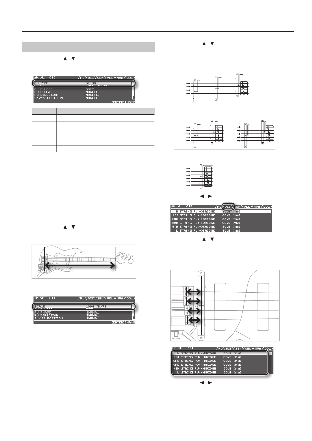
1. Use the cursor [ ] [ ] buttons to move the cursor to “PU
TYPE,” and use the dial to select the type of pickup that’s
installed on your bass.
Value Description
GK-3B Choose this if you’re using a GK-3B.
GK-2B Choose this if you’re using a GK-2B.
PIEZO
PIEZO G This setting is appropriate for a Graph Tech piezo pickup.
PIEZO R This setting is appropriate for an RMC piezo pickup.
A piezo pickup is a type of pickup that is mounted on the bridge of the
bass, and uses a piezoelectric element to detect the vibrations of the
strings.
If you’re using a bass equipped with a GK pickup that’s not of the piezo
type, choose “GK-2B.”
* If you’re not sure which piezo type setting is appropriate, try
selecting dierent choices while you play your bass, and choose the
piezo type that produces the most natural sound.
* If you’ve chosen “PIEZO,” “PIEZO G,” or “PIEZO R” as the PU Type
setting, you’ll be able to make further adjustments to the tone
quality of the high range and low range (p.75).
2. Use the cursor [ ] [ ] buttons to move the cursor to
“SCALE,” and use the dial to specify your bass’s scale length
(the distance between the bridge and nut).
This setting is appropriate if you’re using a piezo pickup that
has a at response.
3. Use the cursor [ ] [ ] buttons to move the cursor to “GK PU
POS,” and use the dial to select the position of the divided
pickup.
For a 4-string bass:
4STR-24STR-1 4STR-3
1st string
2nd string
3rd string
4th string
For a 5-string bass
5STR Lo2
Hi C string
1st string
2nd string
3rd string
4th string
1st string
2nd string
3rd string
4th string
Low B string
5STR Lo1 5STR Hi25STR Hi1
For a 6-string bass:
6STR
Hi C string
1st string
2nd string
3rd string
4th string
Low B string
4. Use the PAGE [ ] [ ] buttons to select the DIS tab.
5. Use the cursor [ ] [ ] buttons to select each string, and
for each string, specify the distance from the center of the
divided pickup to the bridge saddle.
* If PU TYPE is set to one of the piezo-type pickups, this setting is not
necessary.
Choose the closest value in the range of 710–940 mm. For a standard
Jazz Bass type or Precision Bass type, choose LONG JB/PB (864 mm).
For details on the other parameters, refer to “GK SETTING” (p.74).
6. Use the PAGE [ ] [ ] buttons to select the SEN tab.
11
Page 12
Preparations for Using the GR-55
7. Use the cursor [ ] [ ] buttons to move the cursor to the
STRING SENS eld for the lowest string.
Play the lowest string as strongly as you ever expect to play it in actual
performance, and use the dial to adjust the sensitivity as high as
possible without allowing the meter to reach the full-scale position.
* If the level meter reaches the full-scale position, the level is exces-
sive. Lower the sensitivity.
* Depending on the bass you’re using, the level meter might reach
full-scale even if the sensitivity is at minimum. If this is the case,
adjust the distance between the divided pickup and the string so it’s
somewhat greater than the recommendation.
8. In the same way, adjust the sensitivity of the remaining
strings as well.
9. Check the volume balance of the strings.
Play each of the strings at normal strength; if a string sound unusually
loud, lower the sensitivity of that string to minimize any discrepancy in
volume between the strings.
10. Press the [EXIT] button a number of times to return to the
top screen.
These settings are required when you’ve newly installed a divided
pickup on your bass, or when you’ve adjusted the height of the
divided pickup. These settings will be retained even while the power
is switched o. Once you’ve made them correctly, there’s no need
to make them again each time you perform. For details on the other
parameters, refer to “GK SETTING” (p.74).
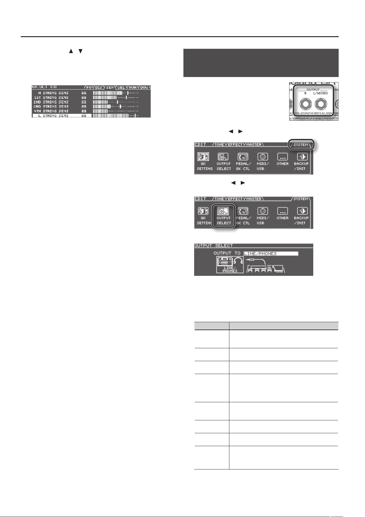
Specifying the Output System (OUTPUT SELECT)
Here’s how to specify the device (amp) that’s
connected to the OUTPUT jacks. The tone will
be adjusted within the GR-55 to ensure that
the optimal sound is produced on the device
you specied.
1. Press the [EDIT] button to access the
EDIT screen.
2. Use the PAGE [
3. Use the cursor [ ] [ ] buttons to select the OUTPUT SELECT
icon, and press the [ENTER] button.
The OUTPUT SELECT screen will appear.
] [ ] buttons to select the SYSTEM tab.
4. Use the dial to select the type of device (amp) that’s
connected to the OUTPUT jacks.
* With the factory settings, this is set to “LINE/PHONES.”
* If headphones are connected, this will automatically be “LINE/
PHONES” regardless of the OUTPUT SELECT setting.
Setting Description
LINE/PHONES
JC-120
SMALL
COMBO
STACK
JC-120 RETURN
COMBO
RETURN
STACK RETURN
This is the appropriate setting when using headphones,
or for when the GR-55 is connected to a keyboard amp,
mixer, or digital recorder.
Choose this setting if the GR-55 is connected to the guitar
input of a Roland JC-120 guitar amp.
Choose this setting if the GR-55 is connected to a small
guitar amp.
Choose this setting if the GR-55 is connected to the
guitar input of a combo-type guitar amp (i.e., an amp that
contains the amp and speaker in a single unit) other than
the JC-120. Depending on the guitar amp you’re using,
using the “JC-120” setting might produce better results.
Choose this setting if the GR-55 is connected to the guitar
input of a stack-type guitar amp (i.e., an amp in which the
amp and speaker are separate units).
Choose this setting if the GR-55 is connected to the
JC-120’s RETURN jack.
Choose this setting if the GR-55 is connected to the
RETURN jack of a combo-type guitar amp.
Choose this setting if the GR-55 is connected to the
RETURN jack of a stack-type guitar amp. You should also
choose the “STACK RETURN” setting when using the GR-55
with a guitar power amp and a speaker cabinet.
12
Page 13
Preparations for Using the GR-55
Setting Description
B-AMP WITH
TWEETER
B-AMP NO
TWEETER
Choose this setting if the GR-55 is connected to a bass
amp that has a tweeter.
Choose this setting if the GR-55 is connected to a bass
amp that does not have a tweeter. The high-frequency
range will be corrected appropriately.
5. Press the [EXIT] button a number of times to return to the
top screen.
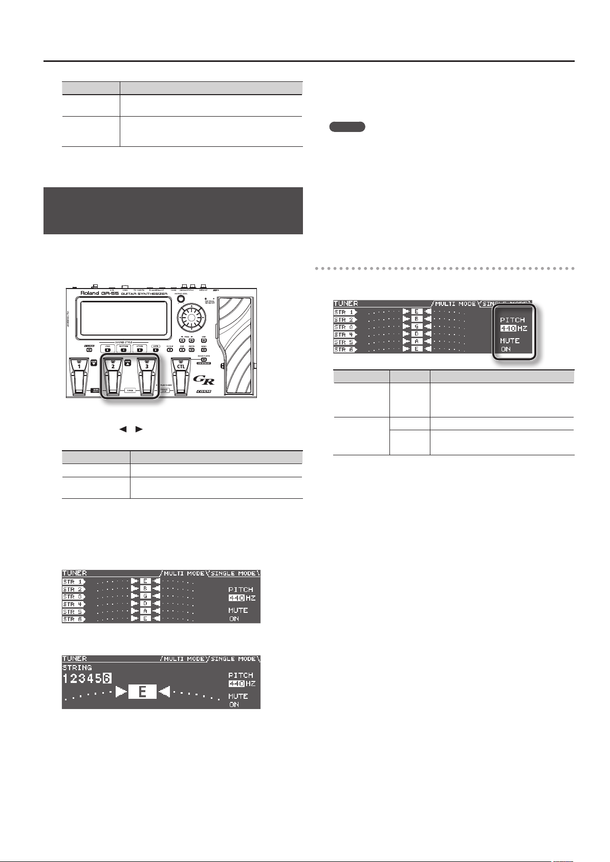
Tuning Your Instrument (the Tuner Function)
Here’s how you can use the GR-55’s Tuner function to tune your guitar
or bass.
1. Press the [2] pedal and [3] pedal simultaneously.
The TUNER screen will appear.
2. Use the PAGE [ ] [ ] buttons to switch between the tabs to
choose the mode of the Tuner function.
Tab Description
MULTI MODE Allows you to tune six strings at the same time.
SINGLE MODE
Allows you to tune by playing a single note on the
specic string you’re tuning.
4. Watch the screen, and tune your instrument so that only the
center indicator is lit.
Repeat steps 3 and 4 until all of the strings are tuned.
MEMO
When tuning a guitar that’s equipped with a vibrato arm, tuning
one string may cause other strings to drift out of tune. In this case,
start by tuning each string approximately, so that the correct note
name is shown, and then retune each string repeatedly until all
strings are tuned correctly.
5. When you’ve nished tuning, press a pedal (any one of the
[1]–[3] pedals or the [CTL] pedal).
You will return to the original screen.
You can also return to the original screen by pressing the [EXIT] button.
Settings in the TUNER screen
In the TUNER screen you can use the cursor buttons and the dial to
make the following settings.
Parameter Value Description
Species the reference pitch.
* With the factory settings this is set to
“440 Hz.”
Sound will not be output while you’re tuning.
* The factory setting is “ON.”
MASTER TUNE
TUNER MUTE
435 Hz
–445 Hz
OFF Sound will be output while you’re tuning.
ON
3. Play an unfretted note on the string that you want to tune,
and tune the string so that the desired note name is shown
in the display.
When using MULTI MODE
When using SINGLE MODE
* In SYSTEM parameter GK SETTING, if DOWN TUNE (p.75) is set to a
value other than “0,” the tuner screen will indicate the note names as
if they were not down tuned.
13
Page 14

MEMO
14
Page 15
Quick Guide
This chapter explains basic operation.
Before you play, you should set your GK pickup’s select switch to “MIX”!
If a dierent setting is selected, the sound might not be output correctly.
Page 16
Selecting and Playing Sounds
Now that you’ve nished with preparations, here’s how to operate the GR-55 while you play.
Adjusting the Output Level
1. Adjust the GR-55’s output level by turning the [OUTPUT LEVEL] knob.
Turning the knob toward the right will increase the volume;
turning the knob all the way toward the left will set the volume to zero.
Normally, you can place the knob near the center position.
Step on the expression pedal.
Raise the GK pickup’s volume knob.
Selecting a Sound (Patch)
What is a Patch?
A “patch” is a unit of sound on the GR-55; in addition to settings
determining the type of sound, the patch also includes eect
settings.
You are free to modify (edit) the settings of a patch and store it in
the GR-55 as a “user patch.” (Patches that are already built into the
GR-55 are called “preset patches.”)
For more about patches, refer to “How the GR-55 Works” (p.22).
What is a Bank?
A “bank” is a collection of three patches.
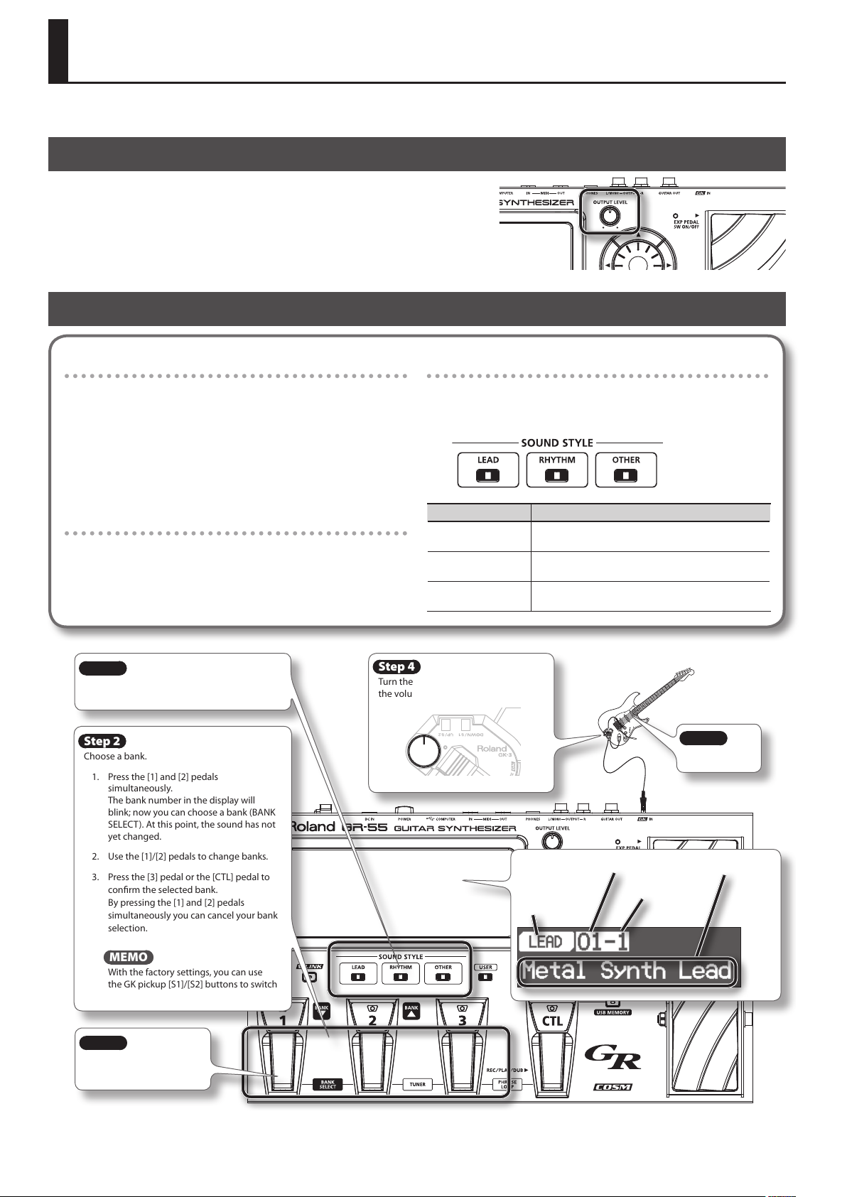
Step 1
Choose the sound style of the sound you want
to play.
Step 2
Choose a bank.
1. Press the [1] and [2] pedals
simultaneously.
The bank number in the display will
blink; now you can choose a bank (BANK
SELECT). At this point, the sound has not
yet changed.
2. Use the [1]/[2] pedals to change banks.
3. Press the [3] pedal or the [CTL] pedal to
conrm the selected bank.
By pressing the [1] and [2] pedals
simultaneously you can cancel your bank
selection.
What is a Sound Style?
The GR-55 lets you select preset patches from three “sound
styles.” First select the style of sound that you want to play, and
then select a patch from within that style.
Sound style Summary
LEAD
RHYTHM
OTHER
Step 4
Turn the GK-3’s volume knob to adjust
the volume of the patch.
Sound style
Sound styles suitable for soloing, such as lead guitar
sounds and wind instruments.
Sound styles suitable for backing, such when comping
chords or playing arpeggios.
Sound styles that include eective, characteristic
synthesized sounds.
Step 5
Play.
Patch bank
Patch number
Patch name
Step 3
Use the [1]–[3] pedals to
select a patch.
16
MEMO
With the factory settings, you can use
the GK pickup [S1]/[S2] buttons to switch
banks.
Page 17
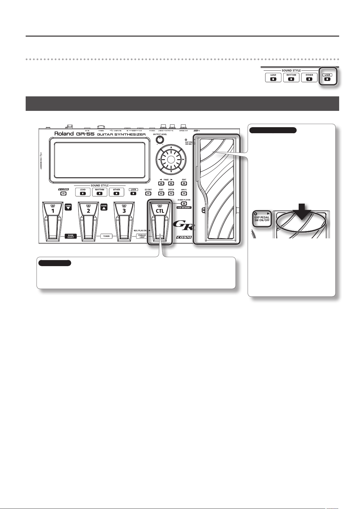
Selecting a User Patch
New patches that you create are saved in the GR-55 as “user patches” (p.18).
Press the [USER] button to select user patches in Step 1 of “Selecting a Sound (Patch).”
The rest of the procedure is the same as when selecting a preset patch.
Playing Your Guitar
You can apply eects to the sound by pressing the following pedals while you play.
Selecting and Playing Sounds
Expression pedal
When you operate this pedal while playing,
the eect assigned to each patch will be
applied.
Normally, the volume will change, but
depending on the patch, a variety of other
eects may be assigned.
If you depress this pedal completely, placing
your weight on the toe, the EXP PEDAL SW
indicator will light, and the expression pedal
will switch to a dierent function. Normally,
it will control an eect such as wah pedal,
but this too may be assigned to a dierent
eect depending on the patch.
[CTL] pedal
When you press this pedal while playing, an eect specied for each patch will be applied; for example,
raising the synthesizer sound by an octave, or extending the decay of the synthesizer note you’re playing.
You are also free to change this eect to your taste (p.61).
You can change each of these eects
according to your taste (p.61).
* When operating the expression pedal,
be careful so as not to get your toes
pinched between the moving portion
and the main part of the GR-55. If there
are young children in your household,
don’t let them use or play with the
GR-55 without adult supervision.
17
Page 18
Selecting and Playing Sounds
Creating an Original Sound
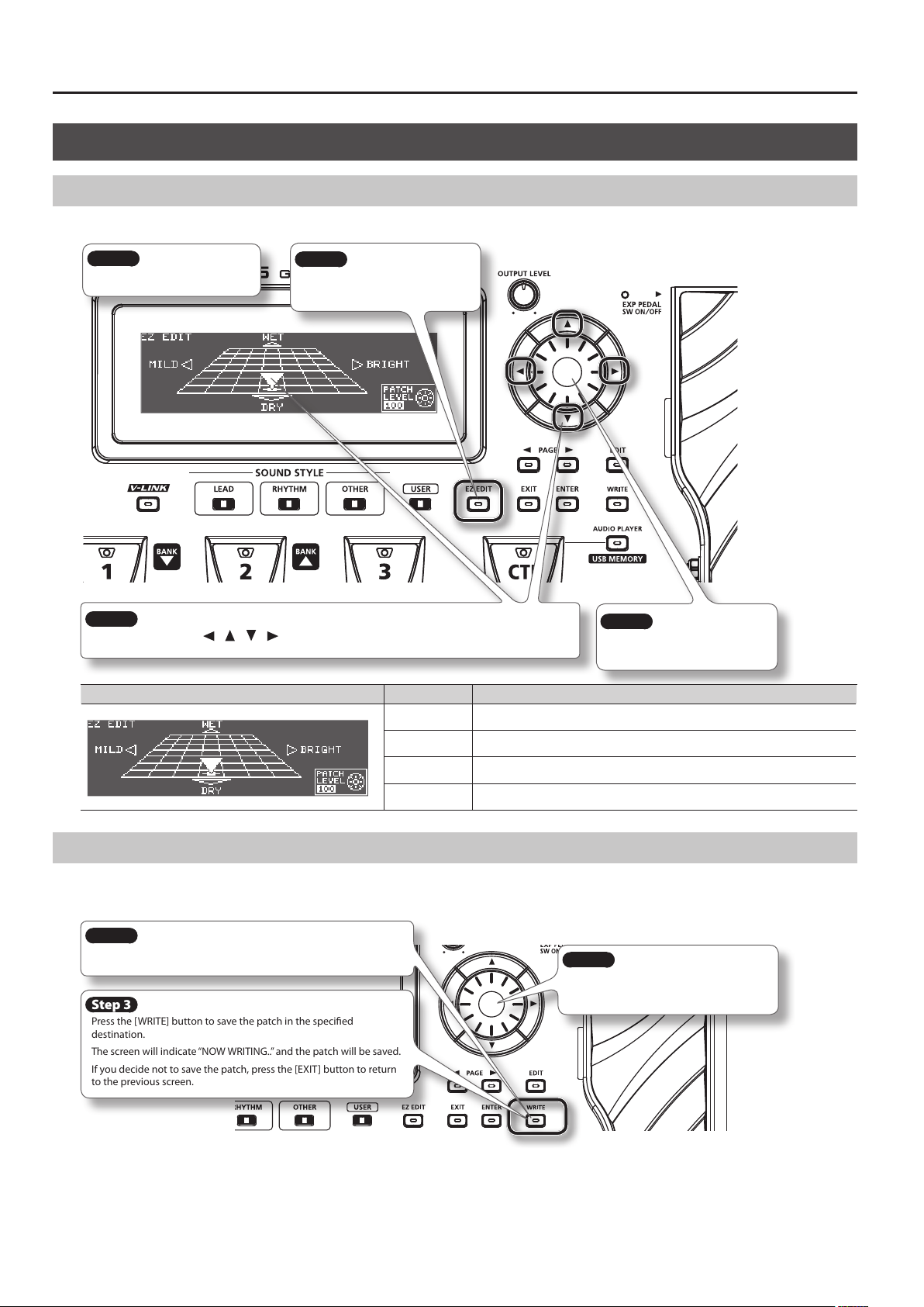
Using the EZ EDIT Function to Create a Sound
You can easily edit the selected patch to your taste by using the GR-55’s EZ EDIT function.
Step 1
Select a patch (p.16).
Step 2
Press the [EZ EDIT] button to access
the EZ EDIT screen.
Step 3
Edit the sound by using [ ] [ ] [ ] [ ] (cursor buttons) to move the cursor within the grid.
Display Parameter Description
WET Gives the sound richer ambience (reverb/delay).
Step 4
Turn the dial to adjust the volume
of the overall patch.
DRY Gives the sound less ambience (reverb/delay).
MILD Helps the sound blend in with the mix.
BRIGHT Helps the sound stand out from the mix.
Saving the Sound You Created
When you’ve created a sound that you like, you should save it as a user patch.
Be aware that if you switch to another patch without saving the patch you edited, the changes you made will be lost.
Step 1
Press the [WRITE] button. The WRITE screen will appear.
Step 3
Press the [WRITE] button to save the patch in the specied
destination.
The screen will indicate “NOW WRITING..” and the patch will be saved.
If you decide not to save the patch, press the [EXIT] button to return
to the previous screen.
* For more about saving patches, refer to “Saving a Patch (PATCH WRITE)” (p.60).
Step 2
Turn the dial to specify the save-destination
patch number.
18
Page 19
Reference
Page 20

Panel Descriptions
Front Panel
[OUTPUT LEVEL] knob
Adjusts the volume of the output jacks
and the headphone jack.
Display
[1] ([BANK ]),
[2] ([BANK ]), [3] pedals
Press these pedals to select patches or
patch banks.
By pressing the [BANK
[BANK ] pedal simultaneously, you
can turn “Bank Select” on/o, allowing
you to select the desired patch bank
(p.16).
By pressing the [2] pedal and [3] pedal
simultaneously, you can tune your
guitar (p.13).
] pedal and
Dial
Use this to switch patches or edit values.
[ ] [ ] [ ] [ ] (cursor buttons)
Use these to move the cursor up/down/
left/right.
[CTL] (control) pedal
By holding down this pedal
you can apply the eect that
is assigned by the patch, such
as sustaining or modifying the
currently playing note.
You are also free to assign other
functions (p.61).
By pressing the [3] pedal and
[CTL] pedal simultaneously,
you can use the PHRASE LOOP
function (p.64).
Expression pedal
When you operate this pedal while playing,
the eect assigned to each patch will be
applied.
Normally, the volume will change, but
depending on the patch, a variety of other
eects may be assigned.
If you depress this pedal completely, placing
your weight on the toe, the EXP PEDAL SW
indicator will light, and the expression pedal
will switch to a dierent function. Normally, it
will control an eect such as wah pedal, but
this too may be assigned to a dierent eect
depending on the patch.
You can change each of these eects
according to your taste (p.61).
* When operating the expression pedal, be careful
so as not to get your toes pinched between the
moving portion and the main part of the GR-55.
If there are young children in your household,
don’t let them use or play with the GR-55
without adult supervision.
Button Description
[V-LINK] Switches V-LINK on/o (p.68).
[LEAD]/[RHYTHM]/
[OTHER]
[USER] Selects user patches (p.17).
[EZ EDIT] Accesses the EZ EDIT screen (p.18).
] [ ]
PAGE [
[EXIT]
[ENTER] Conrms an operation.
[EDIT] Accesses the EDIT screen (p.20).
[WRITE] Saves the patch (p.60).
[AUDIO PLAYER]
Switches the sound style (p.16).
Pressed to navigate to the next left/right
tab in the screen.
Cancels an operation, or takes you to the
next higher level in the screen.
Accesses the AUDIO PLAYER screen (p.65).
The AUDIO PLAYER is available only if
USB memory is inserted in the GR-55.
About the Top Screen
A short while after you turn on the power of the GR-55, this screen
will appear. In this manual, the explanations of various procedures will
start from this screen unless otherwise specied.
Patch bank
Patch number
Sound style
20
Patch name
About the EDIT Screen
The EDIT screen will appear when you press the [EDIT] button. Use the
PAGE [ ] [ ] buttons to switch between tabs in the EDIT screen.
For details on each screen, refer to the following pages.
Screen Description Page
TONE Edit the tone settings. p.23
EFFECT Edit the eect settings. p.38
MASTER Edit overall settings for the patch. p.54
SYSTEM Edit settings for the entire GR-55. p.69
Page 21
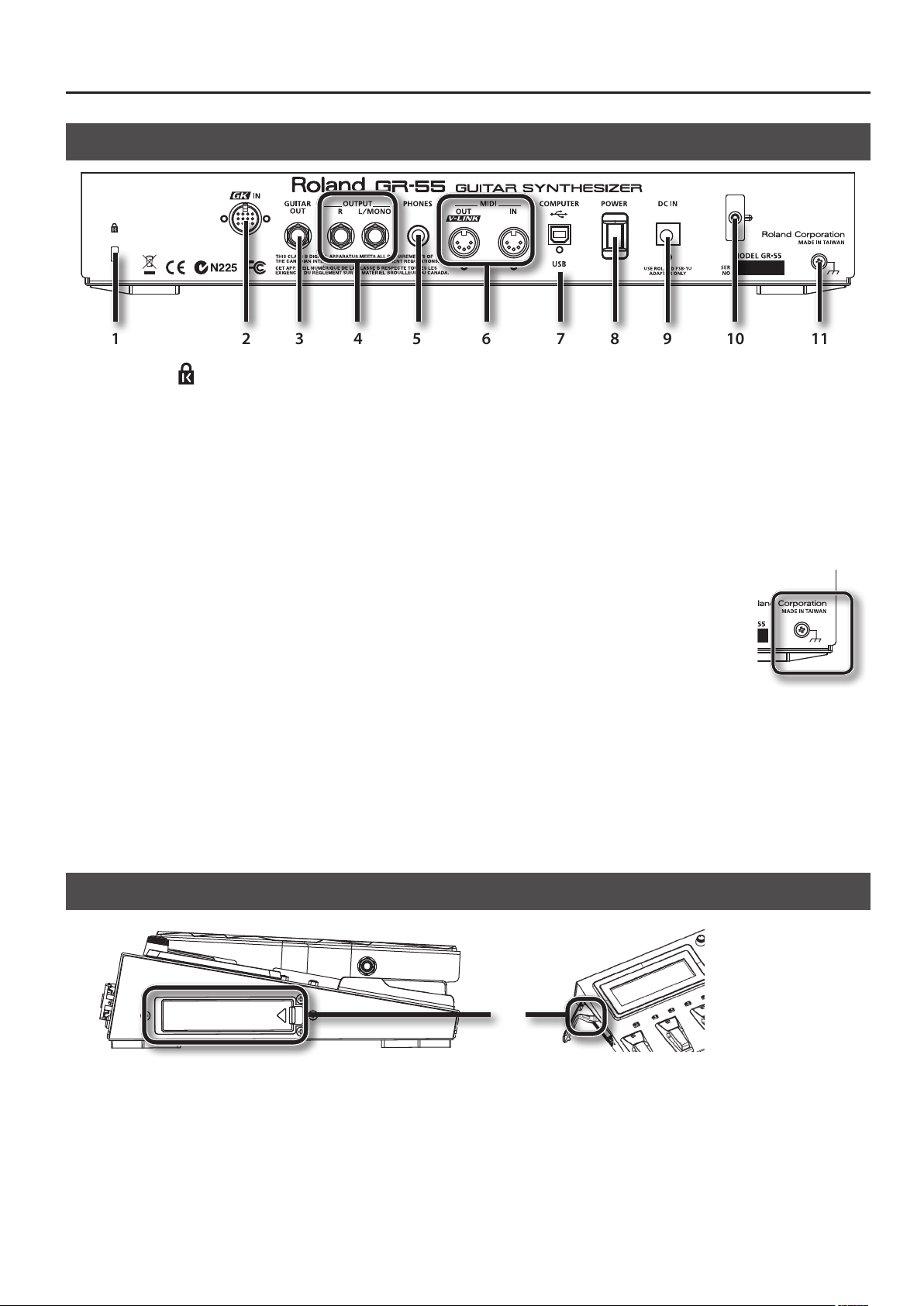
Rear Panel
1 2 3 4 5 6 7 8 9 10 11
Panel Descriptions
1. Security Slot ( )
http://www.kensington.com/
2. GK IN connector
Use the included GK cable (or a separately sold GKC-5 or GKC-10) to
connect your divided pickup to this connector.
* For details on connecting a commercially available GK-equipped
guitar, refer to the guitar manufacturer or your dealer.
3. GUITAR OUT jack
This jack outputs the sound of the guitar’s normal pickup and the
sound of the GR-55’s modeling tone (p.22). Connect it to your guitar
amp.
For details on settings for the sound that is output from the GUITAR
OUT jack, and how to make connections, refer to “GUITAR OUT Jack
Settings (GUITAR OUT)” (p.70).
4. OUTPUT R, L/MONO jacks
These jacks output the sound of your performance using the GR-55. If
connecting to a monaural amp, use the L/MONO jack.
Set the OUTPUT SELECT setting to specify the type of device (amp)
that’s connected to these jacks, as described in “Specifying the Output
System (OUTPUT SELECT)” (p.12).
5. PHONES jack
Connect headphones (sold separately) to this jack (p.8).
6. MIDI connectors (OUT, IN)
Connect other MIDI equipment to these connectors (p.67).
7. USB COMPUTER connector
Use a USB cable to connect the GR-55 to your computer (p.66).
8. [POWER] switch
This turns the power on/o (p.8).
9. DC IN (AC adaptor) jack
Connect the included AC adaptor here (p.8).
10. Cord hook
Use this to fasten the AC adaptor cord so that it will not be unplugged
accidentally (p.8).
11. Functional ground terminal
Depending on the circumstances of a particular
setup, you may experience a discomforting
sensation, or perceive that the surface feels gritty
to the touch when you touch this device or the
metal portions of other objects connected to
it, such as guitars. This is due to an innitesimal
electrical charge, which is absolutely harmless.
However, if you are concerned about this,
connect the ground terminal (see gure) with an external ground.
When the unit is grounded, a slight hum may occur, depending on
the particulars of your installation. If you are unsure of the connection
method, contact the nearest Roland Service Center, or an authorized
Roland distributor, as listed on the “Information” page.
Unsuitable places for connection
• Water pipes (may result in shock or electrocution)
• Gas pipes (may result in re or explosion)
• Telephone-line ground or lightning rod (may be dangerous in the
event of lightning)
Side Panel
1
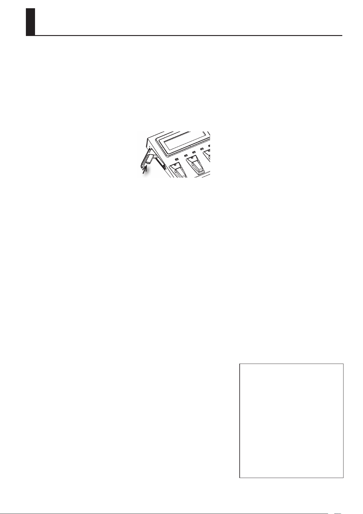
1. USB MEMORY connector
Connect USB memory (sold separately) here.
* Never insert or remove a USB memory while this unit’s power is on. Doing so may corrupt the unit’s data or the data on the USB memories.
* Carefully insert the USB memory all the way in-until it is rmly in place.
21
Page 22
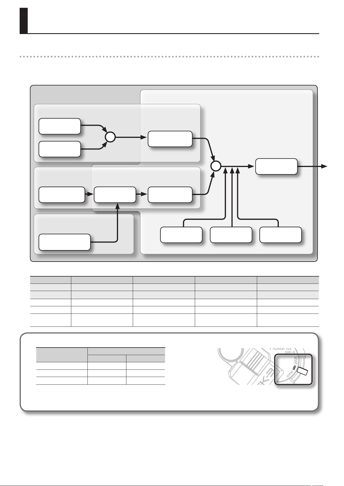
How the GR-55 Works
What is a Patch?
A “patch” is a unit of sound on the GR-55. In addition to settings determining the type of sound, a patch also contains eect settings.
You can modify (edit) the settings of a patch, and save it as a “user patch.” (The patches already built into the GR-55 are called “preset patches.”)
The following illustration shows how a patch is structured internally.
PATCH
Synthesizer sound
PCM TONE 1
+
PCM TONE 2
Modeling sound
MODELING TONE
AMP
Preamp
Normal pickup sound
This is the sound of the guitar’s normal pickup.
NORMAL PICKUP
Eects
This is a synthesizer sound that plays according
to the performance data from your guitar. Two
PCM tones can be layered.
MFX
Multi-eect
This is a modeled sound based on the
audio from each guitar string.
MOD
Guitar eects
These eects processors apply various eects to the
sound.
MFX is a stereo-in multi-eects processor.
AMP uses COSM technology to simulate the
response of the preamp, the size of the speakers, and
the shape of the cabinet.
MOD is a monaural-input guitar eects processor
used in conjunction with AMP.
+
DELAY REVERBCHORUS
EQ
Equalizer
There are some restrictions on the functions that can be used with each tone and with the normal pickup; please refer to the following table.
Parameter HOLD ALTERNATE TUNING TONE EDIT GUITAR OUT
Description Sustain the sound (Hold) Change the tuning of each string Edit the tone Output from GUITAR OUT jack
Page p.55, p.76 p.54 p.24 p.54
PCM tones 1, 2 √ √ √ ×
Modeling tone × √ √ √
Normal pickup × × × √
The available tones will depend on the position of the GK pickup’s select switch.
GK pickup select switch
GK MIX
PCM tones 1, 2 √ √
Modeling tone √ √
Normal pickup × √
* Even if a tone is available, there will be no sound if its tone switch (p.23) is “OFF.”
Normally, you should use the “MIX” setting.
22
Page 23
Editing the Tones (TONE)
As shown in the illustration below, a GR-55 patch consists of several tones.
You can create a new patch by selecting dierent tones or by editing the detailed settings of each tone.
PATCH
PCM TONE 1
PCM TONE 2
MODELING TONE
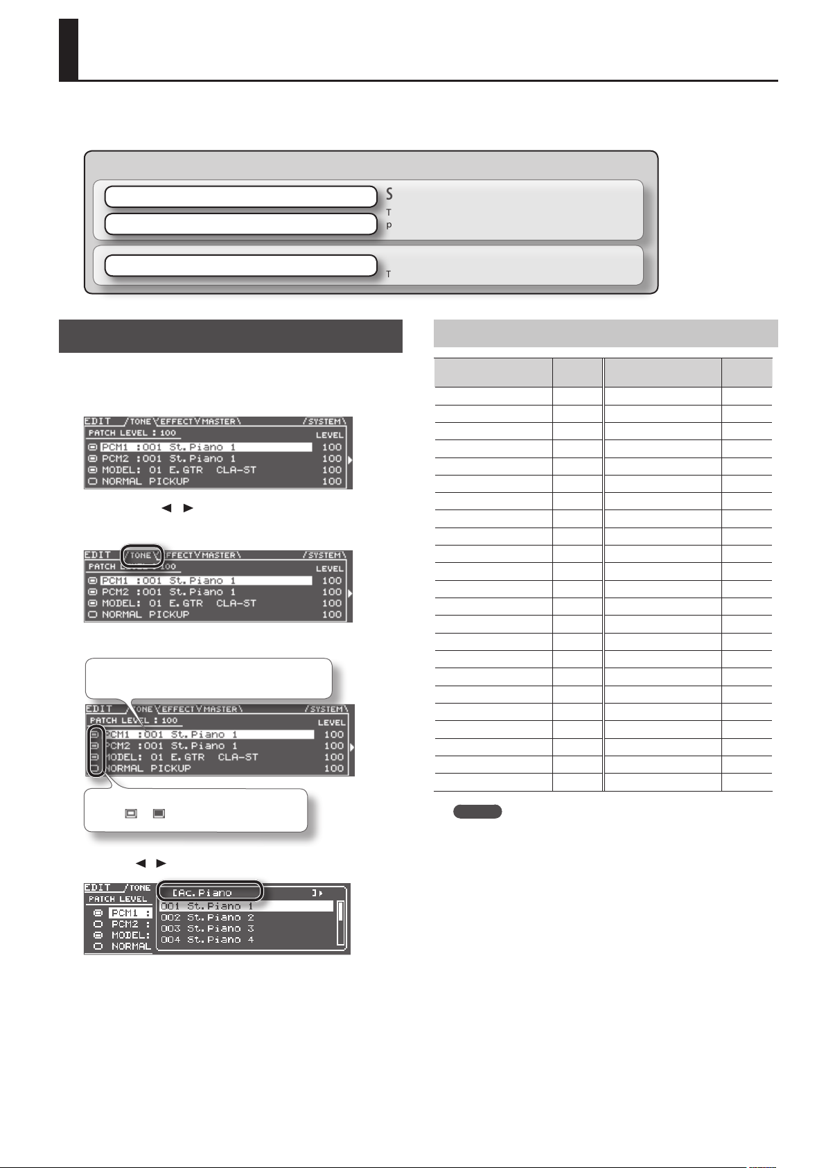
Changing the Tone
Here’s how to create a new sound by changing the tone that’s
selected.
1. Press the [EDIT] button to access the EDIT screen.
2. Use the PAGE [ ] [ ] buttons to access the TONE tab.
The screen shows the structure of the currently selected patch.
3. Select a dierent tone.
Use the cursor buttons to select the tone that you want
to change, and use the dial to select a dierent tone.
Move the cursor to the tone switch, and turn the
tone on /o .
The available tones are listed as shown in the illustration. You can use
the cursor [
] [ ] buttons to select the tone category (p.23).
Synthesizer sound
This is a synthesizer sound that plays according to the
performance data from your guitar. Two tones can be layered.
Modeling sound
This is a modeled sound based on the audio from each guitar string.
Tone Category
Tone category
Ac.Piano 16 Ensemble Strings 22
Pop Piano 3 Orchestral 4
E.Grand Piano 2 Solo Brass 11
E.Piano1 25 Ensemble Brass 7
E.Piano2 13 Wind 7
E.Organ 32 Flute 12
Pipe Organ 5 Sax 7
Reed Organ 1 Recorder 4
Harpsichord 5 Vox/Choir 28
Clav 8 Scat 2
Celesta 1 Synth Lead 123
Accordion 6 Synth Brass 40
Harmonica 2 Synth Pad/Strings 84
Bell 21 Synth Bellpad 17
Mallet 22 Synth PolyKey 45
Ac.Guitar 18 Synth FX 31
E.Guitar 18 Synth Seq/Pop 11
Dist.Guitar 11 Pulsating 32
Ac.Bass 4 Beat&Groove 11
E.Bass 14 Hit 7
Synth Bass 87 Sound FX 37
Plucked/Stroke 18 Percussion 13
Solo Strings 9 Drums 14
MEMO
If you select the “Drums” tone category, there will be fewer
editable parameters than those listed in this manual.
Number
of tones
Tone category
Number
of tones
4. Press the [ENTER] button.
5. When you’ve nished making settings, press the [EXIT]
button.
6. If you want to keep your settings, save the patch (p.60).
23
Page 24
Editing the Tones (TONE)
Editing the Tone
Here’s how to make various settings for the tone.
If you want to edit detailed settings, refer to “Editing a Tone (Detailed
Settings)” (p.24).
Basic operation
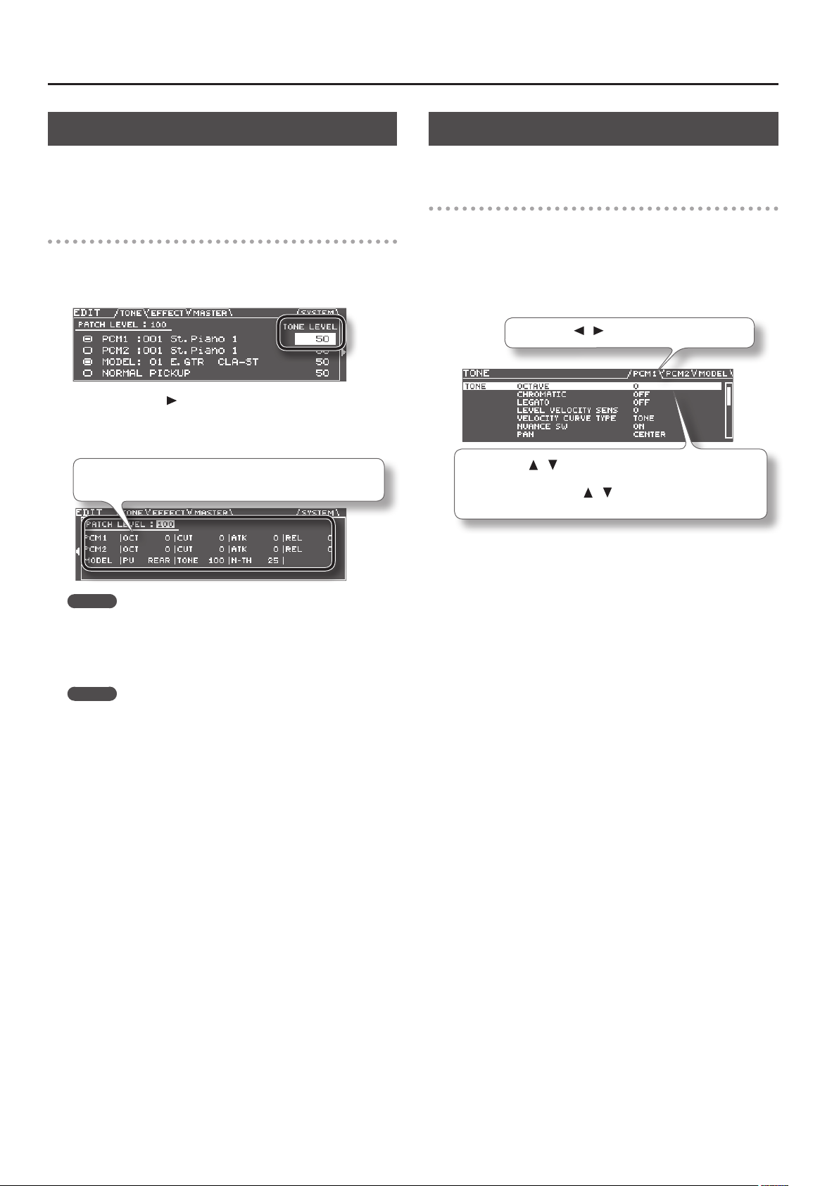
1. In step 3 of “Changing the Tone” (p.23), move the cursor to
the TONE LEVEL eld.
You can use the dial to edit the volume of the tone.
2. Press the cursor [ ] button.
The screen shows the parameters that can be edited for each tone.
3. Edit the parameter settings.
Use the cursor buttons to select the tone parameter that you want to
edit, and use the dial to edit the value.
MEMO
This screen shows the parameters that are marked by a “#” symbol in the
parameter list (p.25 –). The parameters that you can edit will dier for each tone.
4. When you’ve nished editing, press the [EXIT] button.
5. If you want to keep your settings, save the patch (p.60).
MEMO
If you want to adjust the overall volume of the patch, use the cursor
buttons to select the PATCH LEVEL eld, and use the dial to edit the
value.
Value: 0–200
Editing a Tone (Detailed Settings)
Here’s how to edit the tone settings in detail.
Basic operation
1. In step 3 of “Changing the Tone” (p.23), select the tone that
you want to edit.
2. Press the [ENTER] button.
The TONE EDIT screen will appear.
3. Edit the parameter settings.
Use the PAGE [ ] [ ] buttons to switch between tabs.
Use the cursor [ ] [ ] buttons to select the parameter that you want
to edit, and use the dial to edit the value of the parameter.
By holding down the cursor [
make the cursor move faster.
For details on each parameter, refer to “Parameter List (PCM TONE 1/
PCM TONE 2)” (p.25).
4. When you’ve nished editing, press the [EXIT] button.
5. If you want to keep the changes you made, save the patch
(p.60).
] [ ] buttons simultaneously you can
24
Page 25
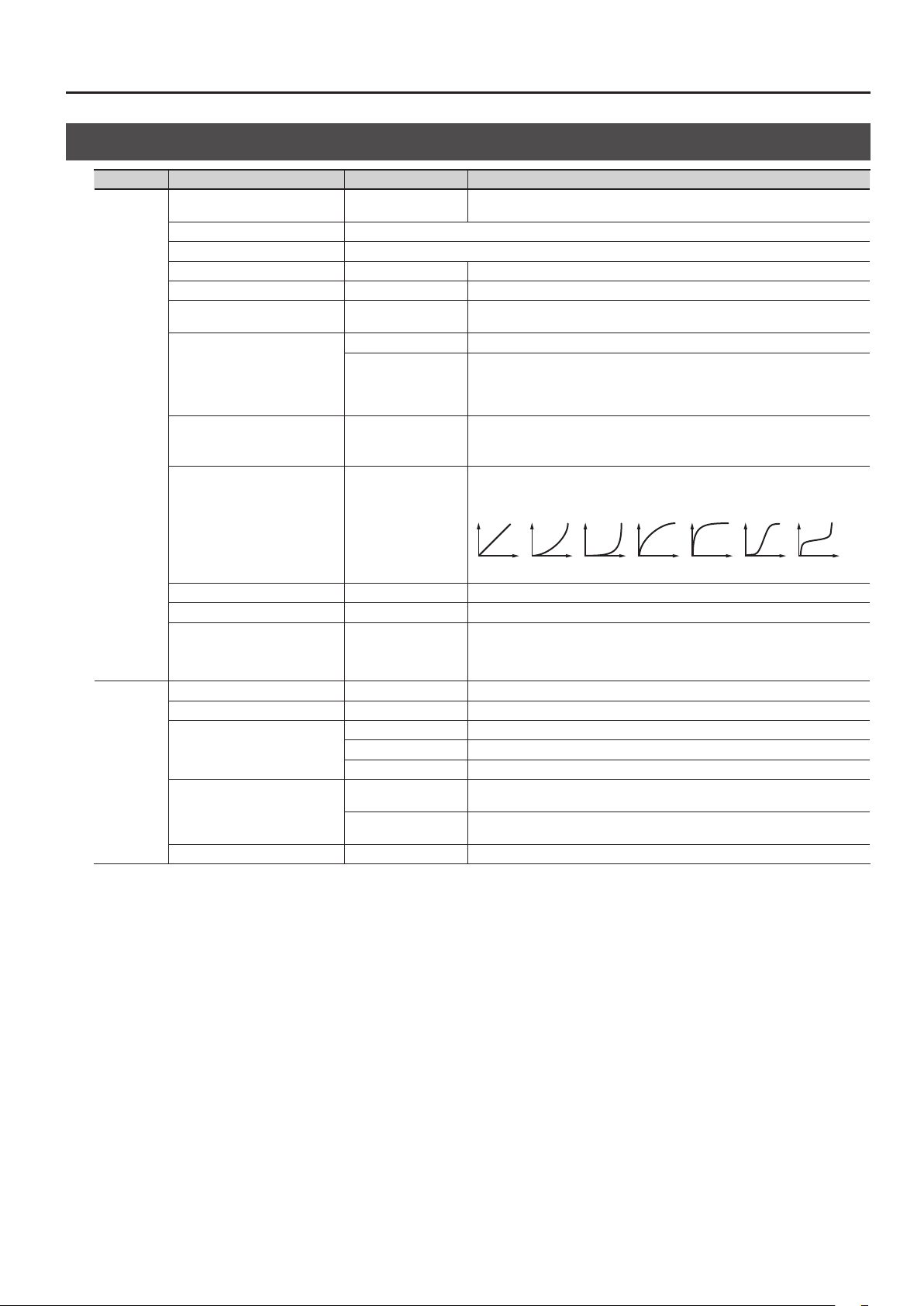
Parameter List (PCM TONE 1/PCM TONE 2)
Group Parameter Value Description
Turns the tone on/o.
Tones that are turned “OFF” will not sound (they are muted).
Turn this “ON” if you want the tone to sound in chromatic steps.
If this is “ON,” the pitch will change only in semitone steps even if you “bend” a string.
When you play notes in a smoothly connected manner by hammering-on or pullingo, only the pitch will change, and no attack will be heard for the subsequently played
note.
The legato function can be used if CHROMATIC is ON.
Adjusts the amount by which the tone’s volume will be aected by your playing
strength.
With positive “+” values, the volume will increase as you play more strongly.
Species the curve by which your playing strength will aect the tone’s volume.
Normally, you should choose “TONE.” The optimal curve for each tone will be used.
If you don’t want the tone’s volume to change, choose “FIX.”
TONE
SWITCH OFF, ON
TONE CATEGORY Selects the category (group) of tones.
TONE NUMBER Selects the tone number.
LEVEL 0–100 Adjusts the volume of the tone.
OCTAVE # -3–+3 Shifts the tone’s pitch in steps of an octave.
CHROMATIC OFF, ON
OFF Turns the Legato function o.
LEGATO
LEVEL VELOCITY SENS -50–+50
VELOCITY CURVE TYPE FIX, 1–7, TONE
ON
Editing the Tones (TONE)
PITCH
1 2 3 4 5 6 7
NUANCE SW OFF, ON Species whether nuances of your performance (p.28) will produce tonal change.
PAN L50–R50 Species the pan setting.
Adjusts the volume of each string.
STRING LEVEL1–6 1–100
PITCH SHIFT -24–+24 Species the tone’s pitch (semitone steps, +/-2 octaves).
PITCH FINE -50–+50 Species the tone’s pitch (in one cent steps; equivalent to 1/100 semitone).
OFF Portamento will not be applied.
PORTAMENTO SW
PORTAMENTO TYPE
PORTAMENTO TIME 0–100 Species the time required for the pitch change when using portamento.
ON Portamento will be applied.
TONE The setting most appropriate for the tone will be used.
RATE
TIME
For the PCM1, PCM2, and MODELING tones, you can specify a value of “0” for each
string that you don’t want to be sounded for that tone; this allows you to create “split”
setups.
The time required for the pitch change is proportionate to the amount of pitch
change.
The pitch change will occupy the same length of time regardless of the amount of
pitch change.
25
Page 26
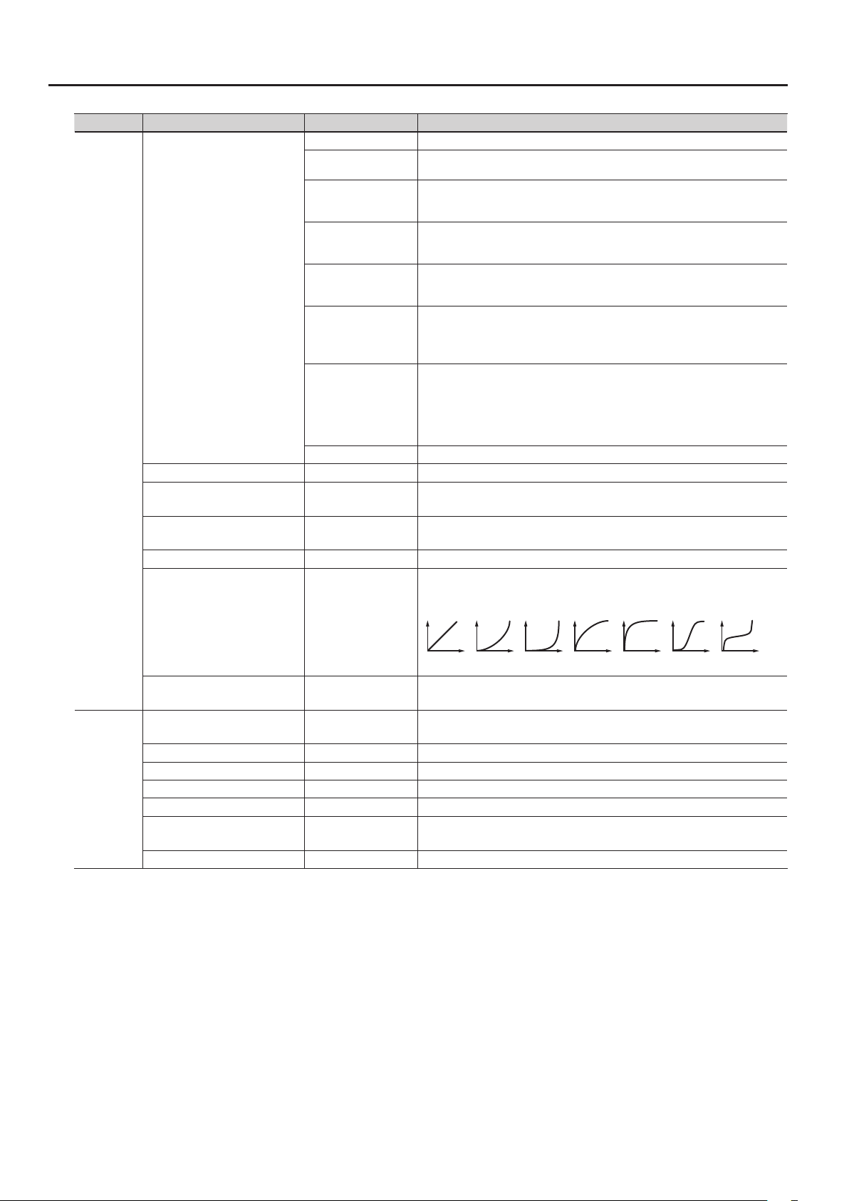
Editing the Tones (TONE)
Group Parameter Value Description
OFF The lter will not be used.
LPF
BPF
HPF
FILTER TYPE
FILTER
CUTOFF # -50–+50 Species the frequency at which the lter will begin to be applied.
RESONANCE -50–+50
CUTOFF VELOCITY SENS -50–+50
CUTOFF NUANCE SENS -50–+50 Species how nuances of your performance (p.28) will aect the lter cuto frequency.
CUTOFF VELOCITY CURVE
PKG
LPF2
LPF3
TONE The setting most appropriate for the tone will be used.
FIX,
1–7,
TONE
Low Pass Filter.
The region above the cuto frequency will be cut, making the sound more mellow.
Band Pass Filter.
The region around the cuto frequency will remain, and the regions above and below
will be cut. This is a useful way to create a distinctive sound.
High Pass Filter.
The region below the cuto frequency will be cut. This is appropriate for percussive
sounds with a distinctive high-frequency component.
Peaking Filter.
The region around the cuto frequency will be emphasized. You can produce a wah
eect by using an LFO to cyclically change the cuto frequency.
Low Pass Filter 2.
The region above the cuto frequency will be cut, but the lter sensitivity will be half
that of LPF. This is suitable for simulating instruments such as acoustic piano.
* If “LPF2” is selected, the RESONANCE setting will be unavailable.
Low Pass Filter 3.
The region above the cuto frequency will be cut, but the lter sensitivity will change
according to the cuto frequency. This is suitable for simulating acoustic instruments,
but even with the same TVF ENVELOPE settings, it will produce a sound with a
dierent nuance than LPF2.
* If “LPF3” is selected, the RESONANCE setting will be unavailable.
Boosts the region near the cuto frequency, giving the sound a distinctive character.
Raising this value excessively may cause oscillation and distortion.
Species the amount by which your playing strength will vary the cuto frequency.
With positive “+” values, stronger playing will raise the cuto frequency.
Species the curve by which your playing strength will aect the cuto frequency.
Normally, you should choose “TONE.” The optimal curve for each tone will be used.
If you don’t want the cuto frequency to be aected, choose “FIX.”
TVF
1 2 3 4 5 6 7
CUTOFF KEYFOLLOW -200–+200
TVF ENV DEPTH -50–+50
TVF ATTACK TIME -50–+50 Adjusts the attack time of the lter envelope.
TVF DECAY TIME -50–+50 Adjusts the decay time of the lter envelope.
TVF SUSTAIN LEVEL -50–+50 Adjusts the sustain level of the lter envelope.
TVF RELEASE TIME -50–+50 Adjusts the release time of the lter envelope.
TVF ATTACK VEL SENS -50–+50
TVF ATK NUANCE SENS -50–+50 Species how nuances of your performance (p.28) will aect the lter attack time.
Species how the pitch of the note you play will aect the cuto frequency.
With positive “+” values, the cuto frequency will rise as you player higher notes.
Adjusts the depth of the TVF envelope.
Higher values will increase the change produced by the TVF envelope.
Species how your playing strength will aect the lter attack time.
With positive “+” values, stronger playing will shorten the attack time.
26
Page 27
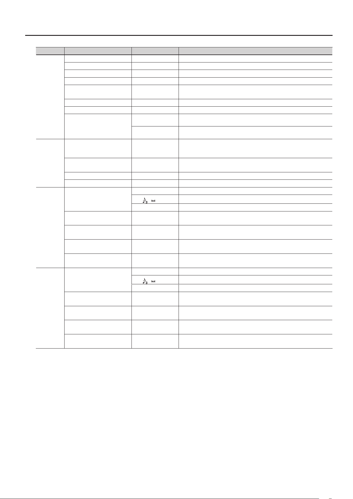
Group Parameter Value Description
TVA ATTACK TIME # -50–+50 Adjusts the attack time of the amp envelope.
TVA DECAY TIME -50–+50 Adjusts the decay time of the amp envelope.
TVA SUSTAIN LEVEL -50–+50 Adjusts the sustain level of the amp envelope.
TVA RELEASE TIME # -50–+50 Adjusts the release time of the amp envelope.
Species how your playing strength will aect the attack time.
With positive “+” values, stronger playing will shorten the attack time.
The next note will be sounded while maintaining the release of a previously played
note sounding on the same string.
Any previously played note sounding on the same string will be forcibly decayed
before the next note is sounded.
Species how your playing strength will aect the depth of the pitch envelope.
With positive “+” values, stronger playing will increase the change produced by the
pitch envelope.
Adjusts the depth of the pitch envelope.
Higher settings will increase the change produced by the pitch envelope.
Makes the LFO rate synchronize to the tempo in units of the note value you specify.
Species how the LFO will aect the pitch.
Choose “OFF” if you don’t want the LFO to aect the pitch.
Species how the LFO will aect the cuto frequency.
Choose “OFF” if you don’t want the LFO to aect the TVF.
Species how the LFO will aect the volume.
Choose “OFF” if you don’t want the LFO to aect the TVA.
Species how the LFO will aect pan (stereo position).
Choose “OFF” if you don’t want the LFO to aect pan.
TVA
PITCH ENV
LFO1
LFO2
TVA ATTACK VEL SENS -50–+50
TVA ATK NUANCE SENS -50–+50 Species how nuances of your performance (p.28) will aect the attack time of the level.
LEVEL NUANCE SENS -50–+50 Species how nuances of your performance (p.28) will aect the volume.
1
RELEASE MODE
2
PITCH ENV VEL SENS -50–+50
PITCH ENV DEPTH -12–+12
PITCH ATTACK TIME -50–+50 Adjusts the attack time of the pitch envelope.
PITCH DECAY TIME -50–+50 Adjusts the decay time of the pitch envelope.
0–100 Species the LFO rate (speed).
LFO1 RATE
LFO1 PITCH DEPTH OFF, -50–+50
LFO1 TVF DEPTH OFF, -50–+50
LFO1 TVA DEPTH OFF, -50–+50
LFO1 PAN DEPTH OFF, -50–+50
LFO2 RATE
LFO2 PITCH DEPTH OFF, -50–+50
LFO2 TVF DEPTH OFF, -50–+50
LFO2 TVA DEPTH OFF, -50–+50
LFO2 PAN DEPTH OFF, -50–+50
–
BPM
TONE The LFO rate will be set appropriately for the tone.
0–100 Species the LFO rate (speed).
–
BPM
TONE The LFO rate will be set appropriately for the tone.
Editing the Tones (TONE)
27
Page 28

Editing the Tones (TONE)
Using the Nuance parameters
The Nuance parameters detect when you play your guitar/bass with a soft touch, and apply a corresponding change to the sound of the
PCM tone.
For example, if CUTOFF NUANCE SENS is set to a positive “+” value, the cuto frequency of the PCM tone will be lowered when you play a
muted or a nger-picked note, producing a softer tone quality.
As another example, you might use PCM TONE 1 to create the sound that will be heard when you pluck the string with a pick, and PCM
TONE 2 to create the sound that will be heard when you pluck the string with your nger. Then set the Nuance parameters as follows,
allowing you to switch between PCM TONE 1 and 2 by alternating your performance technique.
• PCM TONE 1 settings
TONE CATEGORY/NUMBER: the tone sounded for a note played with a pick
LEVEL NUANCE SENS: +50
• PCM TONE 2 settings
TONE CATEGORY/NUMBER: the tone sounded for a note played with your nger
LEVEL NUANCE SENS: -50
To enable the Nuance parameters, turn NUANCE SW “ON” and adjust each NUANCE SENS parameter as desired.
If you want to adjust the nuance so it’s appropriate for the guitar or bass you’re using, set the SYSTEM - GK SETTING parameters NUANCE
DYNAMICS and NUANCE TRIM (p.75).
28
Page 29
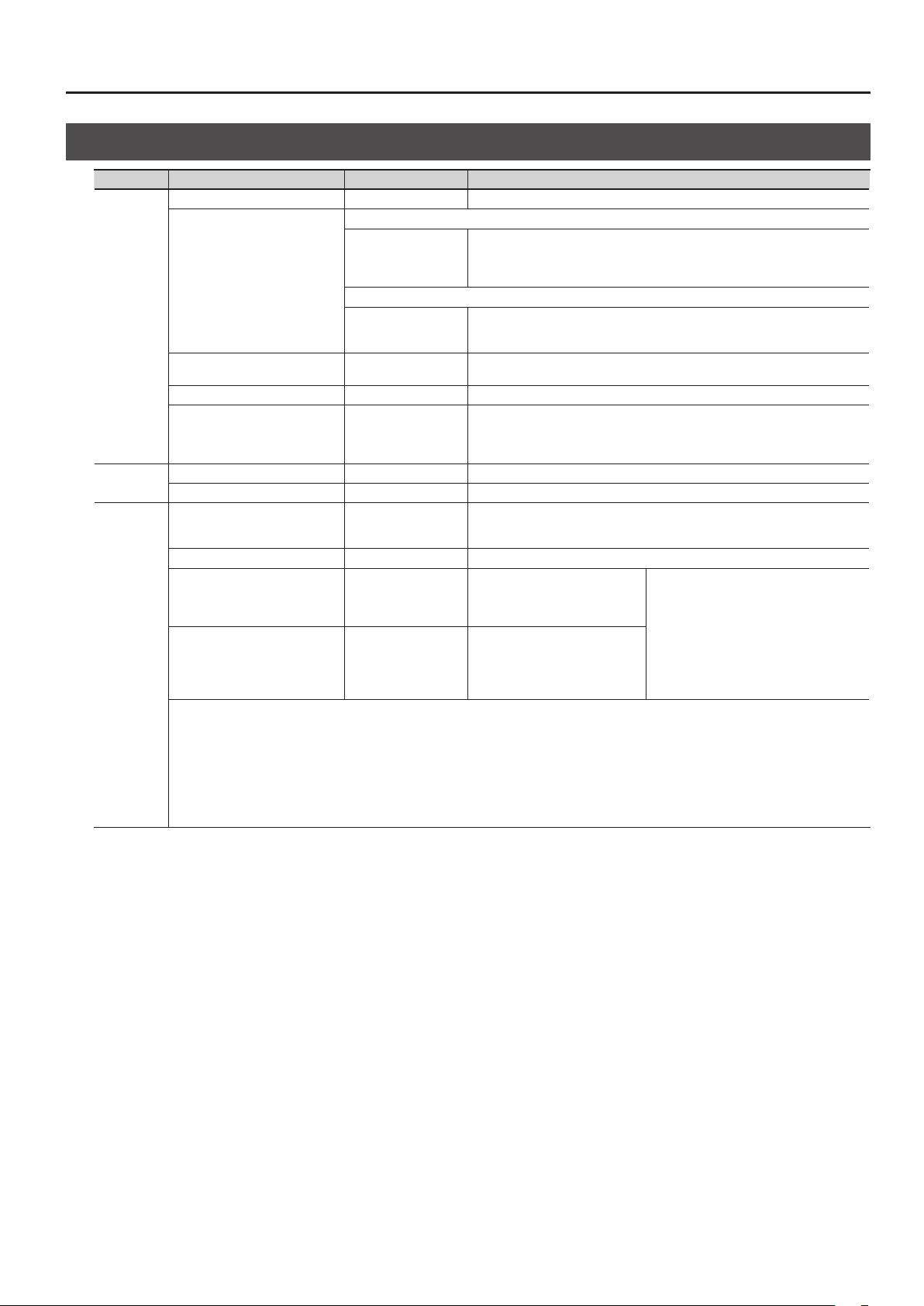
Parameter List (MODELING TONE)
Group Parameter Value Description
SWITCH OFF, ON Turns the tone on/o. Tones turned “OFF” will not sound (i.e., they are muted).
If GUITAR<->BASS is set to “GUITAR” (p.9)
E.GTR,
AC,
E.BASS,
SYNTH
If GUITAR<->BASS is set to “BASS” (p.9)
E.BASS,
SYNTH,
E.GTR
TONE
PITCH
12STR
TONE CATEGORY
TONE NUMBER 001–
LEVEL 0–100 Adjusts the volume of the tone.
STRING LEVEL1–6 0–100
PITCH SHIFT -24–+24 Adjusts the pitch of the tone (in semitone steps, +/-2 octaves).
PITCH FINE -50–+50 Adjusts the pitch of the tone (in one cent steps; equivalent to 1/100 semitone).
12STR SW OFF/ON
DIRECT LEVEL 0–100 Species the volume of the main strings.
SHIFT1–6 -24–+24
FINE1–6 -50–+50
* 12STR cannot be used with any of the following settings (the parameters will not be shown).
• MODELING TONE parameters
TONE CATEGORY=E.BASS (if set to GUITAR input) or E.GTR (if set to BASS input)
PITCH SHIFT≠0
PITCH FINE≠0
• MASTER parameters
ALTERNATE TUNING “SWITCH” =ON
Editing the Tones (TONE)
Selects the category (group) of tones.
Selects the category (group) of tones.
Selects the tone. For an explanation, refer to the following table (TONE CATEGORY:
E.GTR–SYNTH).
Adjusts the volume of each string.
For the PCM1, PCM2, and MODELING tones, you can specify a value of “0” for each
string that you don’t want to be sounded for that tone; this allows you to create “split”
setups.
Turn this on if you want to produce the sound of a 12-string guitar. The sound of a
conventional 6-string guitar will be transformed to the sound of a 12-string guitar
with its supplementary strings.
Adjusts the pitch dierence of each
supplementary string relative to
the corresponding main string, in
semitone steps.
Adjusts the pitch of each
supplementary string in cents
(1/100 semitone steps).
* On a conventional 12-string guitar,
supplementary strings 1 and 2 are tuned
to the same pitch (SHIFT = 0) as the corresponding main string, and supplementary
strings 3–6 are tuned one octave higher
(SHIFT = +12) than the corresponding
main string. Slightly raising each string’s
FINE setting will produce a more realistic
12-string guitar tone.
29
Page 30
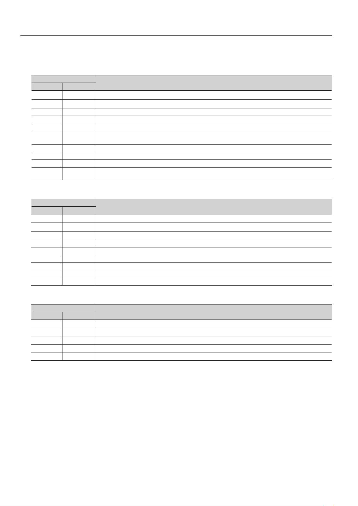
Editing the Tones (TONE)
* Company names and product names appearing in this document are the registered trademarks or trademarks of their respective owners. This
document uses these names in order to appropriately describe the sounds simulated by COSM technology.
TONE CATEGORY: E.GTR
TONE NUMBER (PICKUP)
GUITAR BASS
01: CLA-ST 16: ST This models a Fender Stratocaster, a guitar with three traditional single-coil pickups.
02: MOD-ST — This models a guitar with three EMG active single-coil pickups.
03: H&H-ST — This models a Stratocaster-type guitar with humbucking pickups.
04: TE — This models a Fender Telecaster, a guitar with two single-coil pickups often used in blues and country music.
05: LP 17: LP This models a Gibson Les Paul Standard, a guitar with two humbucking pickups often used in rock.
06: P-90 —
07: LIPS — This models a Danelectro 56-U3, a guitar with three pickups with a distinctive silver “lipstick-style” appearance.
08: RICK — This models a Rickenbacker 360, a semi-hollow body guitar with two unique single-coil pickups.
09: 335 — This models a Gibson ES-335 Dot, a well-known semi-acoustic guitar with two humbucking pickups.
10: L4 —
Description
This models a Gibson Les Paul Junior, a guitar with two single-coil pickups aectionately referred to as “dog ear” or “soap bar”
pickups.
This models a Gibson L-4 CES, a acoustic-body guitar suitable for jazz, equipped with two humbucking pickups and strung with
at-wound strings.
TONE CATEGORY: E.BASS
TONE NUMBER (PICKUP)
GUITAR BASS
— 01: VINT JB This models a Fender Jazz Bass made in the 1960s.
16: JB 02: JB This models a Fender Jazz Bass.
— 03: VINT PB This models a Fender Precision Bass made in the early 1960s.
17: PB 04: PB This models a Fender Precision Bass.
— 05: M-MAN This models a Music Man StingRay Bass made in the 1970s.
— 06: RICK This models a Rickenbacker 4001.
— 07: T-BIRD This models a Gibson Thunderbird.
— 08: ACTIVE This models a typical bass equipped with active pickups.
— 09: VIOLIN This models a Höfner violin bass.
Description
TONE CATEGORY: AC
TONE NUMBER (PICKUP)
GUITAR BASS
11: STEEL — This models a steel-string guitar.
12: NYLON — This models a nylon-string guitar.
13: SITAR — This models a Coral electric sitar. The sitar’s distinctive buzz and tonal change are modeled.
14: BANJO — This models a conventional ve-string banjo.
15: RESO — This models a Dobro-type resonator guitar.
Description
30
Page 31

TONE CATEGORY: SYNTH
TONE NUMBER (PICKUP)
GUITAR BASS
18: ANALOG GR 10: ANALOG GR
19: WAVE SYNTH 11: WAVE SYNTH
20: FILTER BASS 12: FILTER BASS This instrument is similar to a bass synth with a lter applied.
21: CRYSTAL 13: CRYSTAL This is an instrument with a metallic resonance.
22: ORGAN 14: ORGAN
23: BRASS 15: BRASS This instrument produces a clear brass type sound good for leads.
Description
This is the sound of a classic analog polyphonic guitar (bass) synthesizer.
It provides hexa-distortion, with a hexa-VCO and VCF (variable frequency lter) that generates independent
pitch-shiftable sawtooth waves for the six strings, letting you enjoy analog synthesizer sounds that reect the nuances
of your guitar or bass performance.
To change the pitch, use “PITCH A/B” (p.36).
This algorithm directly processes the string signal from the GK pickup to produce the synthesizer sound. It allows a
natural performing feel.
This is a sustained-tone instrument suitable for solo parts or slow songs. As on an organ, you can adjust the volume
level balance of three parameters (FEET 16, 8, 4) to create the desired tone.
E.GTR
CLA-ST, MOD-ST, ST
Group Parameter Value Description
REAR Simulates the sound produced when the rear pickup is used.
R+C Simulates the sound produced when both rear and center pickups are used.
PU
NS
PU SEL #
VOLUME 0–100 Sets the volume. With a setting of 0, there will be no sound.
TONE # 0–100 Adjusts the tone. The standard value is 100; lowering the value creates a softer tone.
SWITCH OFF, ON Turns the noise suppressor on/o.
THRESHOLD # 0–100
RELEASE 0–100
CENTER Simulates the sound produced when the center pickup is used.
C+F Simulates the sound produced when both center and front pickups are used.
FRONT Simulates the sound produced when the front pickup is used.
Adjust this according to the level of the noise. Set this to a higher value if the noise
level is high, or to a lower value if the noise level is low. Adjust this so that the decay of
your guitar still sounds natural.
Species the time from when the noise suppressor begins to operate until the volume
is completely attenuated.
Editing the Tones (TONE)
H&H-ST, TE, LP, P-90, RICK, 335, L4
Group Parameter Value Description
REAR Simulates the sound produced when the rear pickup is used.
PU SEL #
PU
VOLUME 0–100 Sets the volume. With a setting of 0, there will be no sound.
TONE # 0–100 Adjusts the tone. The standard value is 100; lowering the value creates a softer tone.
NS Refer to the NS section of the table for the “CLA-ST, MOD-ST, ST” model in the “E.GTR” section (p.31).
R+F Simulates the sound produced when both rear and front pickups are used.
FRONT Simulates the sound produced when the front pickup is used.
LIPS
Group Parameter Value Description
REAR Simulates the sound produced when the rear pickup is used.
R+C Simulates the sound produced when both center and rear pickups are used.
PU SEL #
PU
VOLUME 0–100 Sets the volume. With a setting of 0, there will be no sound.
TONE # 0–100 Adjusts the tone. The standard value is 100; lowering the value creates a softer tone.
NS Refer to the NS section of the table for the “CLA-ST, MOD-ST, ST” model in the “E.GTR” section (p.31).
CENTER Simulates the sound produced when the center pickup is used.
C+F Simulates the sound produced when both center and front pickups are used.
FRONT Simulates the sound produced when the front pickup is used.
ALL Simulates the sound produced when all pickups are used.
31
Page 32

Editing the Tones (TONE)
AC
STEEL
Group Parameter Value Description
Species the acoustic guitar type.
MA28 The sound of a Martin D-28. Older model known for its exquisitely balanced sound.
TRP-0
BODY TYPE #
BODY
BODY 0–100
TONE # -50–+50
NS Refer to the NS section of the table for the “CLA-ST, MOD-ST, ST” model in the “E.GTR” section (p.31).
GB45
GB SML
GLD40
NYLON
Group Parameter Value Description
BODY # 0–100
BODY
ATTACK 0–100
TONE # -50–+50
The sound of a Martin 000-28. This model features a full low-end resonance and crisp,
distinct contour.
The sound of a Gibson J-45. This vintage model features a unique, seasoned tone with
good response.
The sound of a Gibson B-25. Featuring a compact body, this vintage model is often
used in blues.
The sound of a Guild D-40. This model features warm resonance from the body along
with a delicate string resonance.
Adjusts the body resonation. Raising the value produces more of a sense of the guitar
body in the sound. Lower the value in conditions where feedback is prone to occur.
Adjusts the tone of the body. The standard value is 0; raising the value boosts the high
range.
Adjusts the body resonation. Raising the value produces more of a sense of the guitar
body in the sound. Lower the value in conditions where feedback is prone to occur.
Species the strength of the attack when you pluck the string strongly. As this setting
is increased, the attack will be sharper, and the sound will be crisper.
Adjusts the tone of the body. The standard value is 0; raising the value boosts the high
range.
SITAR
Group Parameter Value Description
FRONT Simulates the sound produced when the front pickup is used.
PU SEL #
SENS 0–100 Adjusts the input sensitivity.
BODY 0–100
BODY
COLOR 0–100 Adjusts the overall tone quality of the sitar.
DECAY 0–100 Adjusts the time it takes following the attack for the tone to change.
BUZZ 0–100
ATTACK LEVEL 0–100 Adjusts the volume level of the attack.
TONE # -50–+50
R+F Simulates the sound produced when both rear and front pickups are used.
REAR Simulates the sound produced when the rear pickup is used.
PIEZO Simulates the sound produced when the piezo pickup is used.
Adjusts the body resonation. Raising the value produces more of a sense of the guitar
body in the sound. Lower the value in conditions where feedback is prone to occur.
Adjusts the amount of characteristic buzz produced by the buzz bridge when the
strings make contact with it.
Adjusts the tone of the body. The standard value is 0; raising the value boosts the high
range.
32
Page 33

BANJO
Group Parameter Value Description
ATTACK # 0–100
BODY
NS Refer to the NS section of the table for the “CLA-ST, MOD-ST, ST” model in the “E.GTR” section (p.31).
RESO 0–100 Adjusts the body resonation. The resonation increases as the value is raised.
TONE # -50–+50
Species the strength of the attack when you pluck the string strongly. As this setting
is increased, the attack will be sharper, and the sound will be crisper.
Adjusts the tone of the body. The standard value is 0; raising the value boosts the high
range.
RESO
Group Parameter Value Description
You can specify how the resulting volume will be aected by changes (loud/soft
SUSTAIN 0–100
BODY
RESO # 0–100 Adjusts the body resonation. The resonation increases as the value is raised.
TONE # -50–+50
NS Refer to the NS section of the table for the “CLA-ST, MOD-ST, ST” model in the “E.GTR” section (p.31).
dynamics) in the guitar string vibrations that are input.
Adjusts the range (time) over which low-level signals are boosted. Larger values will
result in longer sustain.
Adjusts the tone of the body. The standard value is 0; raising the value boosts the high
range.
E.BASS
Editing the Tones (TONE)
JB, VINT JB, T-BIRD
Group Parameter Value Description
REAR VOL 0–100 Sets the volume of the rear pickup.
PU
NS Refer to the NS section of the table for the “CLA-ST, MOD-ST, ST” model in the “E.GTR” section (p.31).
FRONT VOL 0–100 Sets the volume of the front pickup.
VOLUME 0–100 Sets the overall bass volume level. With a setting of 0, there will be no sound.
TONE # 0–100 Adjusts the tone.
PB, VINT PB
Group Parameter Value Description
PU
NS Refer to the NS section of the table for the “CLA-ST, MOD-ST, ST” model in the “E.GTR” section (p.31).
VOLUME 0–100 Sets the volume. With a setting of 0, there will be no sound.
TONE # 0–100 Adjusts the tone.
M-MAN
Group Parameter Value Description
TREBLE # -50–+50 Adjusts the tone for the high frequency range.
PU
NS Refer to the NS section of the table for the “CLA-ST, MOD-ST, ST” model in the “E.GTR” section (p.31).
BASS # 0–100 Adjusts the tone for the low frequency range.
VOLUME 0–100 Sets the volume. With a setting of 0, there will be no sound.
33
Page 34

Editing the Tones (TONE)
RICK
Group Parameter Value Description
REAR VOL 0–100 Sets the volume of the rear pickup.
FRONT VOL 0–100 Sets the volume of the front pickup.
REAR TONE 0–100 Adjusts the tone of the rear pickup.
PU
NS Refer to the NS section of the table for the “CLA-ST, MOD-ST, ST” model in the “E.GTR” section (p.31).
FRONT TONE 0–100 Adjusts the tone of the front pickup.
VOLUME 0–100 Sets the overall bass volume level. With a setting of 0, there will be no sound.
REAR Simulates the sound produced when the rear pickup is used.
PU SEL #
R+F Simulates the sound produced when both rear and front pickups are used.
FRONT Simulates the sound produced when the front pickup is used.
ACTIVE
Group Parameter Value Description
REAR VOL 0–100 Sets the volume of the rear pickup.
FRONT VOL 0–100 Sets the volume of the front pickup.
PU
NS Refer to the NS section of the table for the “CLA-ST, MOD-ST, ST” model in the “E.GTR” section (p.31).
TREBLE # 0–100 Adjusts the tone for the high frequency range.
BASS # 0–100 Adjusts the tone for the low frequency range.
VOLUME 0–100 Sets the overall bass volume level. With a setting of 0, there will be no sound.
VIOLIN
Group Parameter Value Description
REAR VOL 0–100 Sets the volume of the rear pickup.
FRONT VOL 0–100 Sets the volume of the front pickup.
VOLUME 0–100 Sets the overall bass volume level. With a setting of 0, there will be no sound.
PU
NS Refer to the NS section of the table for the “CLA-ST, MOD-ST, ST” model in the “E.GTR” section (p.31).
TREBLE ON # OFF, ON Switches the rear pickup on/o.
BASS ON # OFF, ON Switches the front pickup on/o.
RHYTHM/SOLO #
RHYTHM Selects a lower volume suitable for backing.
SOLO Selects a higher volume suitable for soloing.
34
Page 35

SYNTH
ANALOG-GR
Group Parameter Value Description
Species whether to sound the hexa-VCO (sawtooth wave), the hexa-distortion (square wave), or both.
VCO Only the hexa-VCO will sound.
V+D The hexa-VCO and hexa-distortion will sound together.
DIST Hexa-distortion will sound.
OFF The envelope modulator will not be used.
ON
INV
TONE
ENV
MODE #
COMP OFF, ON
FILTER CUTOFF # 0–100
FILTER RESO # 0–100
This automatically varies the VCF cuto frequency according to the amplitude of the string vibrations. This causes a wah-like tonal change each time you
pluck the string.
ENV MOD SW
ENV MOD SENS 0–100
ENV MOD ATTACK 0–100
Editing the Tones (TONE)
If this is “ON,” the decay time of the hexa-VCO will be extended. If ENV MOD SW is “ON,”
the decay time of the VCF (variable frequency lter) will also be extended.
* The decay time of the hexa-distortion will not be extended.
Adjusts the VCF cuto frequency, specifying the brightness of the sound. Higher
settings will make the sound brighter.
Adjusts the VCF resonance (unique characteristics). Higher settings will boost the
sound in the region of the cuto frequency, producing a sound with more distinctive
characteristics.
Each time you pluck the string, the VCF cuto frequency will move from high toward
low, producing a “wah” eect.
MEMO
Extremely high cuto frequency settings will make this eect dicult to discern.
Each time you pluck the string, the VCF cuto frequency will move from low toward
high, producing an “oo-ahh” that is the opposite of the “wah” eect.
MEMO
Fairly high cuto frequency settings will make this eect easier to discern.
Adjusts the input sensitivity of the envelope modulation. Higher settings of this value
will increase the range of envelope modulation that occurs when you pluck a string
softly.
MEMO
Listen to how the sound is aected while you adjust this parameter. Start with the
setting at about “0,” and play while you gradually raise the value.
Setting ENV MOD ATTACK to “0” will make it easier to hear the change.
Adjusts the attack time of the envelope modulation that occurs when you play a
string.
Higher values produce a slower attack.
35
Page 36

Editing the Tones (TONE)
Group Parameter Value Description
Switches the pitch shift setting of the hexa-VCO that responds to the pitch of the string vibrations.
* Pitch shift applies only to the hexa-VCO; it does not apply to hexa-distortion.
PITCH SW
PITCH A/B
PITCH A/B FINE
PITCH
DUET OFF, ON
This is a Sweep function that smoothly changes the amount of shift when you use PITCH SW to vary the amount of pitch shift.
SWEEP SW OFF, ON
SWEEP RISE 0–100
SWEEP FALL 0–100
Allows you to apply electronic vibrato to the hexa-VCO.
VIBRATO SW OFF, ON
VIBRATO
VIBRATO RATE 0–100
VIBRATO DEPTH 0–100
If you want to use the pitch shift function, set MODE to “VCO” or “V+D.”
OFF The pitch of the original sound will be unmodied.
A The pitch shift specied by PITCH A and PITCH A FINE will be applied.
B The pitch shift specied by PITCH B and PITCH B FINE will be applied.
Adjusts the amount of pitch shift.
* This is eective when PITCH SW is set to anything other than “OFF.”
* The nal amount of pitch shift is the sum of PITCH and PITCH FINE.
-12–+12
Adjusts the amount of pitch shift.
* This is eective when PITCH SW is other than “OFF.”
* The nal amount of pitch shift is the sum of PITCH and PITCH FINE.
-50–+50
Species the amount of pitch shift for PITCH A/B relative to the original pitch, in
semitones. A setting of “-12” is one octave down, and a setting of “+12” is one octave
up.
Applies a ne adjustment to the PITCH A/B pitch. A setting of “-50” is half a semitone
lower, and “+50” is half a semitone higher. This ne setting allows DUET to be used
eectively.
If this is “ON,” a sawtooth wave at the same pitch as the original sound will be added to
the hexa-VCO, making the sound richer.
MEMO
By setting the hexa-VCO’s pitch shift to a PITCH setting such as +/-12 (an octave
up/down), +/- 7 (a perfect fth), or +/-5 (a perfect fourth), you can create thick,
synthesizer-like sounds.
By setting PITCH FINE to about “+/-5” to slightly skew the pitch shift of the hexa-VCO,
you can give the sound greater depth.
Turns the Sweep function on/o.
MEMO
Normally, you’ll use Control Assign to control PITCH SW, and use the control to operate
PITCH SW.
The Sweep function is eective when you operate PITCH SW to change the pitch shift
amount for the hexa-VCO.
It does not operate on changes that occur in the input pitch while the pitch shift
amount is unchanged.
SWEEP RISE and SWEEP FALL have no eect if SWEEP SW is “OFF.”
Adjusts the time over which movement to a higher pitch will occur.
If this is “0,” the change will occur instantly; higher values produce slower change.
Adjusts the time over which movement to a lower pitch will occur.
If this is “0,” the change will occur instantly; higher values produce slower change.
Turns the vibrato eect on/o.
MEMO
If you make Control Assign settings to control VIBRATO SW, you’ll be able to add
powerful vibrato by turning VIBRATO SW “ON” when desired during your performance.
* You can’t apply vibrato to the hexa-distortion.
Species the vibrato rate.
Higher values produce faster vibrato.
Species the vibrato depth.
With a setting of “0” there will be no vibrato. Higher values produce deeper vibrato.
36
Page 37

Editing the Tones (TONE)
WAVE SYNTH
Parameter Value Description
TYPE #
COLOR # 0–100 Adjusts the tone quality. Increasing this value makes the sound brighter.
SAW This is an analog-synth type sound suitable for leads.
SQUARE This is an analog-synth type sound suitable for backing.
FILTER BASS
Parameter Value Description
FILTER CUTOFF # 0–100
FILTER RESO # 0–100
FILTER DECAY 0–100
TOUCH SENS 0–100
COLOR # 0–100 Adjusts the strength of the low range. As the value is increased, the low range will become stronger.
Adjusts the cuto frequency, setting the brightness (hardness) of the sound. The sound gets brighter
(harder) as the value is raised.
Adjusts the resonance (distinctiveness of the sound). As the value is increased, sounds in the frequency
range near the cuto frequency are boosted, making the sound more distinctive and unique.
This sets the speed at which the lter stops. The speed increases as the value of the setting is reduced.
* The FILTER DECAY eect cannot be obtained if the TOUCH SENS value is too low.
This sets the sensitivity when the lter is shifted according to the playing. The shifting of the lter
caused by the playing increases as the value is raised.
When the value is set to “0,” the lter remains set, with no movement.
CRYSTL
Parameter Value Description
ATTACK LENGTH 0–100 This sets the decay time for the attack portion of the sound. A smaller setting results in a shorter attack.
MOD TUNE 0–100 This sets the tuning for the modulation applied to the attack.
MOD DEPTH # 0–100 This sets the depth of the modulation applied to the attack. Larger values result in deeper undulations.
ATTACK LEVEL # 0–100 This sets the volume level of the attack portion.
BODY LEVEL # 0–100 This sets the volume level for the sustained portion of the sound.
SUSTAIN 0–100
Adjusts the range (time) over which low-level signals are boosted. Larger values will result in longer
sustain.
ORGAN
Parameter Value Description
FEET16 # 0–100 This is a long tone at the same pitch as the guitar.
FEET8 # 0–100 This is a long tone one octave higher than the guitar.
FEET4 # 0–100 This is a long tone two octave higher than the guitar.
SUSTAIN 0–100
Adjusts the range (time) over which low-level signals are boosted. Larger values will result in longer
sustain.
BRASS
Parameter Value Description
FILTER CUTOFF # 0–100
FILTER RESO # 0–100
TOUCH SENS # 0–100
SUSTAIN 0–100
Adjusts the cuto frequency, setting the brightness (hardness) of the sound. The
sound gets brighter (harder) as the value is raised.
Adjusts the resonance (distinctiveness of the sound). As the value is increased, sounds in the frequency
range near the cuto frequency are boosted, making the sound more distinctive and unique.
This sets the sensitivity when the lter is shifted according to the playing. The shifting of the lter
caused by the playing increases as the value is raised.
When the value is set to “0,” the lter remains set, with no movement.
Adjusts the range (time) over which low-level signals are boosted. Larger values will result in longer
sustain.
37
Page 38

Eect Settings (EFFECT)
The GR-55 contains seven eects processors (AMP, MFX, MOD, CHORUS, DELAY, REVERB, EQ), which are organized as shown in the illustration below.
(The illustration is for Structure 1.)
AMP
Preamp
MFX
Multi-eect
MOD
Guitar eects
CHORUS
EQ
Equalizer
DELAY REVERB
PCM TONE 1
PCM TONE 2
MODELING TONE
NORMAL PICKUP
By internally connecting eects to the PCM tones and the modeling tone that make up the patch, you can create a broad range of sounds.
5. Switch the eect type.
Switching the Eect Type
Eects are already applied to the patches built into the GR-55. By
editing these settings, you can change the sound to your taste.
1. Select the patch whose eect settings you want to edit (p.16).
2. Press the [EDIT] button to access the EDIT screen.
Use the cursor buttons to select the eect whose type you
want to change, and use the dial to switch the eect type.
3. Use the PAGE [ ] [ ] buttons to select the EFFECT tab.
The screen shows the eects that are applied to the currently selected
patch.
4. Turn an eect on/o.
Use the cursor buttons to select an eect, and use the dial to
turn that eect on /o .
The eect types are listed as shown in the illustration.
6. Press the [ENTER] button.
7. When you’ve nished editing, press the [EXIT] button.
8. If you want to keep the changes you made, save the patch
(p.60).
38
Page 39

Eect Settings (EFFECT)
Editing the Eects
Here’s how to edit the eect settings.
For details on these settings, refer to “Eect Editing (Detailed Settings)”
(p.39).
Basic operation
1. In step 3 of “Switching the Eect Type,” move the cursor to
the EFFECT LEVEL eld.
You can use the dial to adjust the volume of the eect.
2. Press the cursor [ ] button.
The editable parameters for each eect are displayed.
3. Edit the parameters.
Use the cursor buttons to select the eect parameter that you want
to edit.
Use the dial to edit the value.
Eect Editing (Detailed Settings)
Here’s how to make detailed changes to the eect settings.
Basic operation
1. In step 5 of “Switching the Eect Type,” select the eect that
you want to edit.
2. Press the [ENTER] button.
The EFFECT EDIT screen will appear.
3. Edit the parameters.
Use the PAGE [ ] [ ] buttons
to switch between tabs.
Use the cursor [ ] [ ] buttons to select the parameter that you want
to edit, and use the dial to edit the value of the parameter.
By holding down the cursor [
make the cursor move faster.
For details on each parameter, refer to “Parameter List (EFFECT)” (p.41).
4. When you’ve nished editing, press the [EXIT] button.
5. If you want to keep the changes you made, save the patch
(p.60).
] [ ] buttons simultaneously you can
MEMO
This screen shows the parameters that are marked with a “#” symbol in the
parameter list (p.41 –). The parameters that can be edited will dier depending on
the eect.
4. When you’ve nished editing, press the [EXIT] button.
5. If you want to keep the changes you made, save the patch
(p.60).
MEMO
If you want to adjust the overall volume of the patch, use the cursor
buttons to select the PATCH LEVEL eld, and use the dial to edit the
value.
Value: 0–200
39
Page 40

Eect Settings (EFFECT)
Changing the Structure/Specifying the Connection Destination
If you want to change the way in which the eects are arranged, you
can switch the structure.
The GR-55 provides two structures, which have the following features.
This structure uses AMP+MOD and MFX in parallel.
Use this structure when you want to apply the eects
separately; the MFX eect to the synthesizer sound, and
the AMP+MOD eects to the guitar modeling sound.
STRUCTURE 1
This structure connects AMP+MOD and MFX in series.
Use this structure when you want to apply the MFX eect
to the entire patch, and both the AMP+MOD eects and
the MFX eect to the guitar modeling sound.
STRUCTURE 2
1. In step 5 of “Switching the Eect Type,” select the eect that
you want to edit.
2. Press the [ENTER] button.
The EFFECT EDIT screen will appear.
Specifying the connection destination of the tones
6. Use the cursor buttons to move the cursor to the position
shown in the illustration.
If the border is a dashed line, the tone switch is
turned o. You can set the tone switch in the TONE
tab of the EDIT screen (p.23).
7. Use the dial to change the connection destination of the
tone.
Setting Description
BYPS The tone will not use MFX, AMP, or MOD.
AMP The tone is connected to AMP.
MFX The tone is connected to MFX.
8. When you’ve nished editing, press the [EXIT] button.
9. If you want to keep the changes you made, save the patch
(p.60).
10.
Changing the structure
3. Use the PAGE [ ] [ ] buttons to select the STRUCT tab.
4. Use the cursor buttons to move the cursor to the position
shown in the illustration.
5. Use the dial to change the structure.
40
Page 41

Eect Settings (EFFECT)
Parameter List (EFFECT)
* Company names and product names appearing in this document
are the registered trademarks or trademarks of their respective
owners. This document uses these names in order to appropriately
describe the sounds simulated by COSM technology.
About the RATE and DELAY TIME parameters
If you choose “BPM” for these parameters, the value of the parameter will be
determined by the “PATCH TEMPO” (p.58) specied for each patch. This makes it
easy to create an eect sound that is synchronized to the tempo of the song.
AMP
Group Parameter Value Description
SWITCH OFF, ON Turns the AMP OFF/ON.
TYPE
GAIN # 0–120
LEVEL 0–100
TYPE
GAIN SW
SOLO SW OFF, ON
SOLO LEVEL 0–100
BASS # 0–100
MIDDLE # 0–100
TREBLE # 0–100
PRESENCE 0–100
TONE
BRIGHT
Refer to
“AMP Type“
LOW,
MIDDLE,
HIGH
The BRIGHT parameter setting is only available
when BOSS CLEAN, JC-120, JAZZ COMBO,
CLEAN TWIN, PRO CRUNCH, TWEED, BOSS
CRUNCH, BLUES, STACK CRUNCH, BG LEAD, BG
DRIVE, or BG RHYTHM is selected.
OFF BRIGHT is not used.
ON
Species the AMP type.
Adjusts the distortion of the
amp.
Adjusts the overall volume of
the preamp. Take care not to
raise LEVEL excessively.
Switches the amount of the
amp’s distortion in three
levels. LOW, MIDDLE, and HIGH
provide progressively greater
distortion.
Switches to a sound suitable
for solos.
Adjusts the volume when SOLO
SW is “ON.”
Adjusts the tone for the low
frequency range.
Adjusts the tone for the middle
frequency range.
Adjusts the tone for the high
frequency range.
Adjusts the tone for the ultra
high frequency range.
When VO DRIVE, VO LEAD,
VO CLEAN, MATCH DRIVE,
FAT MATCH, or MATCH LEAD
is selected for TYPE, the
PRESENCE parameter functions
as a high cut lter.
BRIGHT is switched on to create
a lighter and crisper tone.
Group Parameter Value Description
Selects the speaker type.
OFF Turns o the speaker simulator.
The built-in speaker of the amp
you selected with AMP TYPE.
An open-back speaker cabinet
with one 8-inch speaker.
An open-back speaker cabinet
with one 10-inch speaker.
An open-back speaker cabinet
with one 12-inch speaker.
An open-back speaker cabinet
with two 12-inch speakers.
A closed-back speaker cabinet
with four 10-inch speakers.
A closed-back speaker cabinet
with four 12-inch speakers.
A double stack of two closedback cabinets, each with four
12-inch speakers.
Models the Shure SM57,
a general-use dynamic
microphone used for
instruments and vocals.
Optimal for use in miking
guitar amps.
Models the Sennheiser MD421,
a dynamic microphone with
extended low end.
Models the AKG C451B, a
small-diaphragm condenser
microphone for use with
instruments.
Models the Neumann U 87, a
condenser microphone with
at response.
Simulates a microphone with
perfectly at response.
Microphone is placed at a
distance from the speaker.
Microphone is placed so it’s
near the speaker.
Microphone is set up so it’s
pointed at the center of the
speaker’s cone.
Microphone is positioned at
the specied distance from the
center of the speaker’s cone.
Adjusts the volume of the
microphone.
SP/MIC
ORIGIN
1x8”
1x10”
SPEAKER TYPE
MIC TYPE
MIC DISTANCE
MIC POSITION
MIC LEVEL 0–100
1x12”
2x12”
4x10”
4x12”
8x12”
This setting selects the simulated microphone
type.
DYN57
DYN421
CND451
CND87
FLAT
Simulates the distance between the
microphone and speaker.
OFF MIC
ON MIC
This simulates the microphone position.
CENTER
1–10
41
Page 42

Eect Settings (EFFECT)
AMP TYPE
Value Description
01: BOSS CLEAN A clean sound that is smooth and warm.
02: JC-120 The sound of the Roland JC-120.
03: JAZZ COMBO A sound suited to jazz.
04: FULL RANGE
05: CLEAN TWIN Models a Fender Twin Reverb.
06: PRO CRUNCH Models a Fender Pro Reverb.
07: TWEED Models a Fender Bassman 4 x 10” Combo.
08: DELUXE CRUNCH Models a Fender Deluxe Reverb.
09: BOSS CRUNCH
10: BLUES A sound suited to blues.
11: WILD CRUNCH A crunch sound with wild distortion.
12: STACK CRUNCH A crunch sound with high gain.
13: VO DRIVE
14: VO LEAD Models the lead sound of the VOX AC-30TB.
15: VO CLEAN Models the clean sound of the VOX AC-30TB.
16: MATCH DRIVE
17: FAT MATCH
18: MATCH LEAD
19: BG LEAD
20: BG DRIVE Models a Mesa/Boogie with Treble Shift Switch on.
21: BG RHYTHM
22: MS1959 I
23: MS1959 I+II
24: MS HIGAIN
25: MS SCOOP
26: R-FIER VINTAGE
27: R-FIER MODERN
28: R-FIER CLEAN
29: T-AMP LEAD Models AMP3 on a Hughes & Kettner TriAmp.
30: T-AMP CRUNCH Models AMP2 on a Hughes & Kettner TriAmp.
31: T-AMP CLEAN Models AMP1 on a Hughes & Kettner TriAmp.
32: BOSS DRIVE A drive sound producing awesome distortion.
33: SLDN
34: LEAD STACK A lead sound with high gain.
35: HEAVY LEAD A powerful lead sound featuring extreme distortion.
36: BOSS METAL A metal sound suited to heavy ris.
37: 5150 DRIVE Models the lead channel of a Peavey EVH 5150.
38: METAL LEAD A lead sound suited to metal.
39: EDGE LEAD A sharp sound suited for lead play.
40: BASS CLEAN A clean sound that is great for use with bass guitars.
A sound with at response.
Good for acoustic guitar.
A crunch sound that faithfully reproduces picking
nuances.
Models the drive sound of a VOX AC-30TB. This is a
sound that it suited to sixties-style British rock.
Models the sound produced using the left input on a
Matchless D/C-30, a modern tube amp widely used in
styles from blues to rock.
Models the sound of a Matchless modied for high
gain.
Models the sound produced using the right input on a
Matchless D/C-30.
Models the lead sound of the Mesa/Boogie combo
amp, a tube amp that was very popular in the late ‘70s
and ‘80s.
Models the rhythm channel of a Mesa/Boogie combo
amp.
Models the sound produced using Input I on a
Marshall 1959 Super Lead amp. This is a trebly sound
suited to hard rock.
The sound of connecting Inputs I and II of the Marshall
1959 amp in parallel, creating a sound with a stronger
low end than I.
Models the sound of a Marshall modied with a
midrange boost.
This is a Marshall sound that’s been tweaked for a
metal sound.
Models the sound of the Channel 2 VINTAGE Mode on
the Mesa/Boogie DUAL Rectier.
Models the sound of the Channel 2 MODERN Mode on
the Mesa/Boogie DUAL Rectier.
Models the sound of the Channel 1 CLEAN Mode on
the Mesa/Boogie DUAL Rectier.
Models a Soldano SLO-100, a very popular tube amp
in the 1980s.
Value Description
41: BASS CRUNCH
42: BASS HIGAIN A high-gain sound suitable for use with bass guitars.
A crunch sound with natural distortion that sounds
great with bass guitars.
MOD
Group Parameter Value Description
SWITCH OFF, ON Turns MOD OFF/ON.
Adjusts the pan position.
The PAN parameter is valid even if
SWITCH is “OFF.”
Species the MOD type.
Adjusts the eect in response to the
level of noise.
A value of 0 switches o the noise
suppressor.
Setting this higher than necessary
may cause no sound to be produced
when the guitar is played at low
volume.
Adjusts the time from when the noise
suppressor begins to function until
the noise level reaches “0.”
TYPE
NS
PAN L50–R50
EFFECT TYPE
SWITCH OFF, ON Turns the noise suppressor on/o.
THRESHOLD 0–100
RELEASE 0–100
Refer to
“MOD Type“
42
Page 43

Eect Settings (EFFECT)
MOD Type
01: OD/DS
Parameter Value Description
Selects the type of eect.
MID BOOST
CLEAN BOOST
TREBLE BOOST
BLUES OD
CRUNCH
NATURAL OD
OD-1
T-SCREAM Models an Ibanez TS-808.
TURBO OD
WARM OD A warm overdrive.
TYPE
DRIVE # 0–120 Adjusts the intensity of the distortion.
TONE # -50– +50 Adjusts the brightness of the sound.
LEVEL 0–100 Adjusts the volume level for OD/DS.
DISTORTION A basic, traditional distortion sound.
MILD DS Produces a mild distortion.
MID DS Distortion that emphasizes the midrange.
RAT Models a ProCo RAT.
GUV DS Models a Marshall Guv’nor.
DST+ Models an MXR Distortion Plus.
MODERN DS
SOLID DS A distortion sound that has a lot of edge.
STACK
LOUD
METAL ZONE
LEAD
60S FUZZ
OCT FUZZ Models an Ace Tone FUZZ.
MUFF FUZZ Models an Electro-Harmonix Big Mu π.
A booster with unique characteristics in the
midrange. This produces a great sound for
solos.
This can be used not only as a booster, but
also can be used by itself to provide clean
tones with punch.
A booster that has bright sound
characteristics.
The crunch sound of the BOSS BD-2.
A unique overdrive that faithfully reproduces
the nuances of picking.
A brilliant crunch sound to which the
distortion elements of an amp have been
added.
Produces the natural sounding distortion of
a slightly overdriven amp.
The sound of the BOSS OD-1. It produces
sweet, mild distortion.
The high-gain overdrive sound of the BOSS
OD-2.
The deep distortion sound of a large
stack-type amp.
A fat sound to which the distortion elements
of a stack amp have been added.
This distortion sound is ideal for performing
heavy ris.
The sound of the BOSS MT-2. It produces a
wide range of metal sounds, from old style
to slash metal.
Produces a distortion sound with the
smoothness of an overdrive along with a
deep distortion.
Models a Fuzz Face. It produces a fat fuzz
sound.
02: WAH
Parameter Value Description
Selects the wah mode.
MODE #
TYPE (*1)
PEDAL POSITION
(*1)
SENS (*2) 0–100
FREQUENCY (*2) 0–100
PEAK (*2) 0–100 Adjusts the intensity of the wah sound.
LEVEL 0–100 Adjusts the volume level of the eect.
(*1) Setting available with MODE set to “MANUAL.”
(*2) Setting available with MODE set to “T.UP” or “T.DOWN.”
(*3) Assign the controller to the expression pedal.
As the assigned parameter, set the PEDAL/GK CTL setting EXP-FUNCTION to“MOD
CONTROL” (p.57).
MANUAL (*3)
T.UP
T.DOWN
Selects the type of wah.
CRY WAH
VO WAH Models the sound of the VOX V846.
FAT WAH This is a wah sound featuring a bold tone.
LIGHT WAH
7STRING WAH
RESO WAH
0–100
You can use an expression pedal to control
wah.
Produces a wah eect matched to the
intensity of picking.
Models the sound of the CRY BABY wah
pedal popular in the ‘70s.
This wah has a rened sound with no
unusual characteristics.
This expanded wah features a variable range
compatible with seven-string and baritone
guitars.
This completely original eect oers
enhancements on the characteristic
resonances produced by analog synth lters.
Adjusts the position of the wah pedal.
This parameter will change when you
operate the expression pedal.
Adjusts the sensitivity of response to the
input sound.
Adjusts the center frequency of the Wah
eect.
03: COMP
Parameter Value Description
SUSTAIN # 0–100 Adjusts the sustain for the sound.
ATTACK # 0–100 Adjusts the attack (onset) of the sound.
LEVEL 0–100 Adjusts the volume level of the eect.
04: LIMITER
Parameter Value Description
THRESHOLD # 0–100
RELEASE # 0–100 Adjusts the release time.
LEVEL 0–100 Adjusts the volume level of the eect.
When the input signal level exceeds the level
set here, limiting will be applied.
05: OCTAVE
Parameter Value Description
Adds sound one octave lower than the input,
OCTAVE LEVEL 0–100
DIRECT LEVEL # 0–100 Adjusts the volume level of the direct sound.
giving a weighty feel to the sound. Play single
notes, with the other strings muted completely.
This parameter species the volume of the
octave-lowered sound.
43
Page 44

Eect Settings (EFFECT)
06: PHASER
Parameter Value Description
Selects the number of stages that the phaser eect uses.
4 STAGE
TYPE
RATE #
DEPTH # 0–100 Adjusts the richness of the eect.
RESONANCE # 0–100 Adjusts the intensity of the eect.
LEVEL 0–100 Adjusts the volume level of the eect.
8 STAGE
12 STAGE
BI-PHASE
0–100, BPM
A four-phase eect. A light phaser eect
is obtained.
An eight-phase eect. This is the most
common phaser eect.
A twelve-phase eect. A deep phase
eect is obtained.
A phaser with two phase-shift circuits
connected in series.
Adjusts the speed of the eect.
–
07: FLANGER
Parameter Value Description
RATE #
DEPTH # 0–100 Adjusts the richness of the eect.
MANUAL # 0–100
RESONANCE # 0–100 Adjusts the intensity of the eect.
LEVEL 0–100 Adjusts the volume level of the eect.
0–100,
BPM
–
Adjusts the speed of the eect.
Adjusts the modulation frequency of the
anger eect.
08: TREMOLO
Parameter Value Description
RATE #
DEPTH # 0–100 Adjusts the intensity of the eect.
WAVE SHAPE # 0–100
LEVEL 0–100 Adjusts the volume level of the eect.
0–100,
BPM
–
Adjusts the speed of the eect.
Adjusts the curve for changes in the volume
level. A higher value makes the change more
abrupt.
09: ROTARY
Parameter Value Description
RATE SLOW #
RATE FAST #
DEPTH # 0–100 Adjusts the richness of the eect.
SPEED SELECT
#
LEVEL 0–100 Adjusts the volume level of the eect.
0–100,
–
BPM
0–100,
–
BPM
SLOW, FAST
Adjusts the rate of modulation when SPEED
SELECT is “SLOW.”
Adjusts the rate of modulation when SPEED
SELECT is “FAST.”
Changes the rotation speed of the simulated
speaker.
10: UNI-V
Parameter Value Description
RATE #
DEPTH # 0–100 Adjusts the richness of the eect.
LEVEL 0–100 Adjusts the volume level of the eect.
0–100,
BPM
–
Adjusts the speed of the eect.
11: PAN
Parameter Value Description
RATE #
DEPTH # 0–100
WAVE SHAPE # 0–100
LEVEL 0–100 Adjusts the volume level of the eect.
0–100,
BPM
–
Adjusts the rate of change in the pan position.
Adjusts the intensity of the change in the pan
position.
Adjusts the curve for pan position changes.
Higher values produce steeper change.
12: DELAY
Parameter Value Description
Use this to choose the type of delay.
SINGLE A simple monaural delay.
PAN
STEREO
TYPE
TIME #
FEEDBACK # 0–100 Adjusts the number of repetitions for the delay.
EFFECT LEVEL 0–120
REVERSE Produces the eect of playback in reverse.
ANALOG Produces a mild analog delay sound.
TAPE
MODULATE
HICUT
1–3400 msec,
–
BPM
Provides a tap delay eect that divides the
delay time between the left and right channels.
The direct sound is output from the left
channel, and the eect sound is output from
the right channel.
Provides the characteristic wavering sound of
a tape echo.
A delay with a pleasant amount of modulation
added.
Produces a warm-sounding delay with the high
frequencies attenuated.
Adjusts the delay time.
Adjusts the volume level of the eect.
When TYPE is set to “REVERSE,” this adjusts the
balance of direct and eect sound.
13: CHORUS
Parameter Value Description
Use this to choose the type of chorus.
MONO
STEREO 1
TYPE
RATE #
DEPTH # 0–100 Adjusts the richness of the eect.
EFFECT LEVEL 0–100 Adjusts the volume level of the eect.
STEREO 2
MONO MILD
STEREO 1
MILD
STEREO 2
MILD
0–100,
–
BPM
This chorus eect outputs the same sound from
the left and right channels.
A stereo chorus eect that adds dierent
chorus sounds to the left and right channels.
This stereo chorus uses spatial synthesis, with
the direct sound output in the left channel and
the eect sound output in the right channel.
Features a more suppressed high end than
MONO.
Features a more suppressed high end than
STEREO 1.
Features a more suppressed high end than
STEREO 2.
Adjusts the speed of the eect.
44
Page 45

Eect Settings (EFFECT)
14: EQ
LOW GAIN LO-MID GAIN
LO-MID FREQ HI-MID FREQ
Parameter Value Description
LOW CUT
LOW GAIN # -20–+20 dB Adjusts the low frequency range tone.
LO-MID FREQ
LO-MID Q 0.5–16
LO-MID GAIN # -20–+20 dB Adjusts the low-middle frequency range tone.
HI-MID FREQ
HI-MID Q 0.5–16
HI-MID GAIN # -20–+20 dB Adjusts the high-middle frequency range tone.
HIGH GAIN # -20–+20 dB Adjusts the high frequency range tone.
HIGH CUT
LEVEL -20–+20 dB Adjusts the overall volume of the equalizer.
FLAT,
55–800 Hz
20.0 Hz–
10.0 kHz
20.0 Hz–
10.0 kHz
700 Hz–
11.0 kHz,
FLAT
HI-MID GAIN HIGH GAIN
Frequency
Species the frequency at which the low
cut lter begins to take eect. When FLAT is
selected, the low cut lter will have no eect.
Species the center of the frequency range that
will be adjusted by the LO-MID GAIN.
Adjusts the width of the area aected by the EQ
centered at the LO-MID FREQ. Higher values will
narrow the area.
Species the center of the frequency range that
will be adjusted by the HI-MID GAIN.
Adjusts the width of the area aected by the EQ
centered at the HI-MID FREQ. Higher values will
narrow the area.
Species the frequency at which the high
cut lter begins to take eect. When FLAT is
selected, the high cut lter will have no eect.
MFX
Group Parameter Value Description
SWITCH OFF, ON Turns MFX OFF/ON.
Name of
MFX type
indicated
PAN L50–R50
EFFECT TYPE
Refer to “MFX
Type”
Adjusts the pan position.
The PAN parameter is valid even if
SWITCH is “OFF.”
Species the MFX type.
MFX Type
01: EQ
This EQ lets you modify the tone quality by adjusting the low range, two mid-ranges,
and the high range.
L in
R in
Parameter Value Description
LOW FREQ 200, 400 Hz
LOW GAIN # -15–+15 dB
MID1 FREQ 200–8000 Hz
MID1 GAIN # -15–+15 dB
MID1 Q 0.5, 1.0, 2.0, 4.0, 8.0
MID2 FREQ 200–8000 Hz
MID2 GAIN # -15–+15 dB
MID2 Q 0.5, 1.0, 2.0, 4.0, 8.0
HIGH FREQ 2000, 4000, 8000 Hz
HIGH GAIN # -15–+15 dB
LEVEL 0–100 Adjusts the output volume.
4-Band EQ
4-Band EQ
L out
R out
Species the frequency of the
low range.
Adjusts the gain of the low
range.
Adjusts the frequency of middle
range 1.
Adjusts the gain of middle
range 1.
Species the width of middle
range 1.
Set a higher value for Q to
narrow the range to be aected.
Adjusts the frequency of middle
range 2.
Adjusts the gain of middle
range 2.
Species the width of middle
range 2.
Set a higher value for Q to
narrow the range to be aected.
Species the frequency of the
high range.
Adjusts the gain of the high
range.
45
Page 46

Eect Settings (EFFECT)
SAW1 SAW2
02: SUPER FILTER
This is a lter with an extremely sharp slope. The cuto frequency can be varied
cyclically.
L in
R in
Parameter Value Description
FILTER TYPE #
FILTER SLOPE
FILTER CUTOFF # 0–100
FILTER
RESONANCE #
FILTER GAIN # 0–+12 dB
MODULATION SW OFF, ON
MODULATION WAVE
Super Filter
Super Filter
Selects the type of lter.
Species the frequencies allowed to pass through the
lter.
LPF Frequencies below the cuto
BPF
HPF Frequencies above the cuto
NOTCH
Species the slope of the lter (steepness, in terms of the
attenuation per octave).
-12 dB Gentle
-24 dB Steep
-36 dB Extremely steep
0–100
Species how the cuto frequency will be modulated.
TRI Triangle wave
SQR Square wave
SIN Sine wave
SAW1 Sawtooth wave (upward)
SAW2 Sawtooth wave (downward)
L out
R out
Frequencies in the region of the
cuto
Frequencies other than the
region of the cuto
Adjusts the cuto frequency of
the lter.
Increasing this value will raise the
cuto frequency.
Adjusts the lter resonance level.
Increasing this value will
emphasize the region near the
cuto frequency.
Adjusts the amount of boost for
the lter output.
This is the on/o switch for cyclic
change.
03: PHASER
This is a stereo phaser. A phase-shifted sound is added to the original sound and
modulated.
L in
R in
Parameter Value Description
MODE
MANUAL # 0–100
RATE #
DEPTH # 0–100 Adjusts the depth of modulation.
POLARITY
RESONANCE # 0–100 Adjusts the amount of feedback.
CROSS
FEEDBACK
MIX 0–100
LOW GAIN -15–+15 dB Adjusts the gain of the low range.
HIGH GAIN -15–+15 dB
LEVEL 0–100 Adjusts the output volume.
Phaser
Mix
Mix
Phaser
4-STAGE,
8-STAGE,
12-STAGE
0–100, BPM
Selects whether the left and right phase of the modulation
will be the same or the opposite.
INVERSE
SYNCHRO
-98–+98%
2-Band
EQ
2-Band
EQ
This sets the number of stages in
the phaser.
Adjusts the basic frequency
from which the sound will be
modulated.
–
Adjusts the rate of the
modulation.
The left and right phase will be
opposite. When using a mono
source, this spreads the sound.
The left and right phase will
be the same. Select this when
inputting a stereo source.
Adjusts the proportion of the
phaser sound that is fed back
into the eect. Negative (-)
settings will invert the phase.
Adjusts the level of the phaseshifted sound.
Adjusts the gain of the high
range.
L out
R out
04: STEP PHASER
This is a stereo phaser. The phaser eect will be varied gradually.
RATE
DEPTH 0–100 Adjusts the depth of modulation.
ATTACK 0–100
LEVEL 0–100 Adjusts the output volume.
46
0–100, BPM
L in
–
Adjusts the rate of modulation.
Adjusts the speed at which the
cuto frequency will change.
This is eective if MODULATION
WAVE is SQR, SAW1, or SAW2.
R in
Parameter Value Description
MODE
MANUAL # 0–100
RATE #
DEPTH 0–100 Adjusts the depth of modulation.
Step Phaser
Step Phaser
4-STAGE,
8-STAGE,
12-STAGE
0–100, BPM
Mix
Mix
–
2-Band
EQ
2-Band
EQ
Species the number of stages in
the phaser.
Adjusts the basic frequency
from which the sound will be
modulated.
Adjusts the rate of the
modulation.
L out
R out
Page 47

Eect Settings (EFFECT)
SAW1 SAW2
SAW1 SAW2
L
L
Parameter Value Description
Selects whether the left and right phase of the modulation
will be the same or the opposite.
POLARITY
RESONANCE # 0–100 Adjusts the amount of feedback.
CROSS
FEEDBACK
STEP RATE #
MIX 0–100
LOW GAIN -15–+15 dB
HIGH GAIN -15–+15 dB
LEVEL 0–100 Adjusts the output volume.
INVERSE
SYNCHRO
-98–+98%
0–100, BPM
–
The left and right phase will be
opposite. When using a mono
source, this spreads the sound.
The left and right phase will
be the same. Select this when
inputting a stereo source.
Adjusts the proportion of the
phaser sound that is fed back
into the eect. Negative (-)
settings will invert the phase.
Adjusts the rate of the stepwise
change in the phaser eect.
Adjusts the level of the phaseshifted sound.
Adjusts the gain of the low
range.
Adjusts the gain of the high
range.
05: RING MODULATOR
This is an eect that applies amplitude modulation (AM) to the input signal, producing
bell-like sounds. You can also change the modulation frequency in response to
changes in the volume of the sound sent into the eect.
L in
Ring Mod
2-Band EQ
L out
06: TREMOLO
Cyclically alters the volume.
L in
R in
Parameter Value Description
MOD WAVE #
RATE #
DEPTH # 0–100 Adjusts the depth of the eect.
LOW GAIN -15–+15 dB Adjusts the gain of the low range.
HIGH GAIN -15–+15 dB
LEVEL 0–100 Adjusts the output volume.
Tremolo
Tremolo
2-Band EQ
2-Band EQ
Species how the volume will be modulated.
TRI Triangle wave
SQR Square wave
SIN Sine wave
SAW1/2 Sawtooth wave
0–100, BPM
–
L out
R out
Adjusts the frequency of the
change.
Adjusts the gain of the high
range.
07: AUTO PAN
Cyclically varies the stereo location of the sound.
R in
Ring Mod
Parameter Value Description
FREQUENCY # 0–127
SENS # 0–100
POLARITY
LOW GAIN -15–+15 dB
HIGH GAIN -15–+15 dB
BALANCE # D100:0W–D0:100W
LEVEL 0–100 Adjusts the output volume.
2-Band EQ
Determines whether the frequency modulation moves
towards higher frequencies or lower frequencies.
UP Higher frequencies
DOWN Lower frequencies
R out
Adjusts the frequency at which
modulation is applied.
Adjusts the amount of frequency
modulation applied.
Adjusts the gain of the low
frequency range.
Adjusts the gain of the high
frequency range.
Adjusts the volume balance
between the direct sound (D)
and the eect sound (W).
L in
R in
Parameter Value Description
MOD WAVE
Auto Pan
Auto Pan
2-Band EQ
2-Band EQ
Species how the pan position will be varied.
TRI Triangle wave
SQR Square wave
SIN Sine wave
SAW1/2 Sawtooth wave
R
RATE #
DEPTH # 0–100 Adjusts the depth of the eect.
LOW GAIN -15–+15 dB Adjusts the gain of the low range.
HIGH GAIN -15–+15 dB
LEVEL 0–100 Adjusts the output volume.
0–100, BPM
–
L out
R out
R
Adjusts the frequency of the
change.
Adjusts the gain of the high
range.
47
Page 48

Eect Settings (EFFECT)
Balance D
08: SLICER
By applying successive cuts to the sound, this eect turns a conventional sound into a
sound that appears to be played as a backing phrase. This is especially eective when
applied to sustain-type sounds.
L in
R in
Parameter Value Description
PATTERN # P01–P20
RATE #
ATTACK # 0–100
INPUT SYNC SW OFF, ON
INPUT SYNC
THRESHOLD
LEVEL 0–100 Adjusts the output volume.
Slicer
Slicer
0–100, BPM
0–100
–
L out
R out
Selects the slice pattern used to
cut the sound.
Species the rate at which the
16-step sequence will repeat.
Adjusts the speed at which the
level changes between steps.
Species whether an input
note will cause the sequence to
resume from the rst step of the
sequence (ON) or not (OFF).
Adjusts the volume at which an
input note will be detected.
09: VK ROTARY
This type provides modied response for the rotary speaker, with the low end boosted
further.
This eect features the same specications as Roland VK-7 organ’s built-in rotary
speaker.
L in
Rotary
R in
Parameter Value Description
This sets the rotational speed of the rotating speaker.
SPEED
BRAKE OFF, ON
WOOFER SLOW
SPEED #
WOOFER FAST
SPEED #
WOOFER TRANS UP 0–100
WOOFER TRANS
DOWN
WOOFER LEVEL 0–100 Adjusts the volume of the woofer.
TWEETER SLOW
SPEED #
TWEETER FAST
SPEED #
TWEETER TRANS UP 0–100
TWEETER TRANS
DOWN
TWEETER LEVEL 0–100
SLOW Slow
FAST Fast
0–100
0–100
0–100
0–100
0–100
0–100
2-Band EQ
2-Band EQ
Switches the rotation of the
rotary speaker.
When this is turned on, the
rotation will gradually stop. When
it is turned o, the rotation will
gradually resume.
Adjusts the low-speed rotation
speed of the woofer.
Adjusts the high-speed rotation
speed of the woofer.
Adjusts the rate at which the
woofer rotation speeds up when
the rotation is switched from
SLOW to FAST.
Adjusts the rate at which the
woofer rotation speeds up when
the rotation is switched from
FAST to SLOW.
These are the settings of the
tweeter. The parameters are the
same as for the woofer.
L out
R out
Parameter Value Description
SPREAD 0–10
LOW GAIN -15–+15 dB Adjusts the gain of the low range.
HIGH GAIN -15–+15 dB
LEVEL 0–100 Adjusts the output volume.
Species how the sound of the
rotary speaker will be spread.
Adjusts the gain of the high
range.
10: HEXA-CHORUS
This type uses a six-phase chorus (six layers of chorused sound) to give richness and
spatial spread to the sound.
L in
Balance D
Hexa Chorus
R in
Parameter Value Description
PRE DELAY 0.0–100 msec
RATE #
DEPTH # 0–100 Adjusts the depth of modulation.
PRE DELAY
DEVIATION
DEPTH DEVIATION -20–+20
PAN DEVIATION 0–20
BALANCE # D100:0W–D0:100W
LEVEL 0–100 Adjusts the output volume.
0–100, BPM
0–20
–
L out
Balance W
Balance W
R out
Adjusts the delay time from the
direct sound until the chorus
sound is heard.
Adjusts the rate of the
modulation.
Adjusts the deviation with
respect to the sounding of the
various chorus sounds.
Adjusts the dierence in
modulation depth between each
chorus sound.
Adjusts the dierence in stereo
location between each chorus
sound.
With a setting of “0,” all of the
sounds will be panned to the
center. With a setting of “20,” each
of the chorused sounds will be
spread apart at 60 degree angles
relative to the center.
Adjusts the volume balance
between the direct sound (D)
and the chorus sound (W).
48
Page 49

Eect Settings (EFFECT)
Balance D
Balance D
Balance D
Balance D
Balance D
Balance D
11: SPACE-D
This is a multiple chorus that applies two-phase modulation in stereo. It gives no
impression of modulation, but produces a transparent chorus eect.
L in
Space D
Space D
R in
Parameter Value Description
PRE DELAY 0.0–100 msec
RATE #
DEPTH # 0–100
PHASE 0–180 deg
LOW GAIN -15–+15 dB Adjusts the gain of the low range.
HIGH GAIN -15–+15 dB
BALANCE # D100:0W–D0:100W
LEVEL 0–100 Adjusts the output volume.
0–100, BPM
–
2-Band
EQ
Balance W
Balance W
2-Band
EQ
Adjusts the delay time from the
direct sound until the chorus
sound is heard.
Adjusts the rate of the
modulation.
Adjusts the depth of the
modulation.
Adjusts the spatial spread of the
sound.
Adjusts the gain of the high
range.
Adjusts the volume balance
between the direct sound (D)
and the chorus sound (W).
L out
R out
12: FLANGER
This is a stereo anger.
It produces a metallic resonance that’s comparable to the sound a jet plane makes
when ascending/descending. A lter is provided so that you can adjust the timbre of
the anged sound.
L in
Flanger
Feedback
Feedback
Flanger
R in
Parameter Value Description
Selects the type of lter.
OFF No lter is used.
FILTER TYPE
CUTOFF FREQ 200–8000 Hz
PRE DELAY 0.0–100 msec
RATE #
DEPTH # 0–100
PHASE 0–180 deg
LPF
HPF
0–100, BPM
–
2-Band
EQ
Balance W
Balance W
2-Band
EQ
Cuts the frequency range above
the CUTOFF FREQ.
Cuts the frequency range below
the CUTOFF FREQ.
Adjusts the center frequency
when using the lter to cut a
specic frequency range.
Adjusts the delay time from
when the direct sound begins
until the anger sound is heard.
Adjusts the rate of the
modulation.
Adjusts the depth of the
modulation.
Adjusts the spatial spread of the
sound.
L out
R out
Parameter Value Description
Adjusts the proportion of the
FEEDBACK # -98–+98%
LOW GAIN -15–+15 dB Adjusts the gain of the low range.
HIGH GAIN -15–+15 dB
BALANCE # D100:0W–D0:100W
LEVEL 0–100 Adjusts the output volume.
anger sound that is fed back
into the eect. Negative (-)
settings will invert the phase.
Adjusts the gain of the high
range.
Adjusts the volume balance
between the direct sound (D)
and the chorus sound (W).
13: STEP FLANGER
This is a anger in which the anger pitch changes in steps. The speed at which the
pitch changes can also be specied in terms of a note-value of a specied tempo.
L in
Step Flanger
Feedback
Feedback
Step Flanger
R in
Parameter Value Description
Selects the type of lter.
OFF No lter is used.
FILTER TYPE
CUTOFF FREQ 200–8000 Hz
PRE DELAY 0.0–100 msec
RATE #
DEPTH 0–100
PHASE 0–180 deg
FEEDBACK # -98–+98%
STEP RATE #
LOW GAIN -15–+15 dB Adjusts the gain of the low range.
HIGH GAIN -15–+15 dB
BALANCE # D100:0W–D0:100W
LEVEL 0–100 Adjusts the output volume.
LPF
HPF
0–100, BPM
0–100, BPM
–
–
2-Band
EQ
Balance W
Balance W
2-Band
EQ
Cuts the frequency range above
the CUTOFF FREQ.
Cuts the frequency range below
the CUTOFF FREQ.
Adjusts the center frequency
when using the lter to cut a
specic frequency range.
Adjusts the delay time from
when the direct sound begins
until the anger sound is heard.
Adjusts the rate of the
modulation.
Adjusts the depth of the
modulation.
Adjusts the spatial spread of the
sound.
Adjusts the proportion of the
anger sound that is fed back
into the eect. Negative (-)
settings will invert the phase.
Adjusts the rate (period) of pitch
change.
Adjusts the gain of the high
range.
Adjusts the volume balance
between the direct sound (D)
and the chorus sound (W).
L out
R out
49
Page 50

Eect Settings (EFFECT)
L in
L out
R out
14: GUITAR AMP SIMULATOR
This is an eect that simulates the sound of a guitar amplier.
Pre Amp
Speaker
R in
Parameter Value Description
PRE AMP SW OFF, ON Turns the amp switch on/o.
JC-120,
CLEAN TWIN,
MATCH DRIVE,
BG LEAD,
MS1959I,
MS1959II,
PRE AMP TYPE #
PRE AMP VOLUME # 0–100
PRE AMP MASTER # 0–100
PRE AMP GAIN LOW, MIDDLE, HIGH
PRE AMP BASS
PRE AMP MIDDLE
PRE AMP TREBLE
PRE AMP PRESENCE 0–100
PRE AMP BRIGHT OFF, ON
SPEAKER SW OFF, ON
SPEAKER TYPE # (See the table below.) Selects the type of speaker.
MIC SETTING 1, 2, 3
MIC LEVEL 0–100
DIRECT LEVEL 0–100
PAN L50–R50
LEVEL 0–100 Adjusts the output volume.
MS1959I+II,
SLDN LEAD,
METAL 5150,
METAL LEAD,
OD-1,
OD-2 TURBO,
DISTORTION,
FUZZ
0–100
Species the type of guitar amp.
Adjusts the volume and amount
of distortion of the amp.
Adjusts the volume of the entire
pre-amp.
Species the amount of pre-amp
distortion.
Adjust the tone of the bass/mid/
treble frequency ranges.
PRE AMP MIDDLE cannot be set
if MATCH DRIVE is selected as the
PRE AMP TYPE.
Adjusts the tone of the ultra-high
frequency range.
Turning this ON produces a
sharper and brighter sound.
This is available only if PRE AMP
TYPE is set to “JC-120,” “CLEAN
TWIN,” or “BGLEAD.”
Determines whether the signal
passes through the speaker (ON),
or not (OFF).
Adjusts the location of the
microphone that’s capturing the
sound of the speaker.
This can be adjusted in three
steps, from 1 to 3, with the
microphone becoming more
distant as the value increases.
Adjusts the volume of the
microphone.
Adjusts the volume of the direct
sound.
Adjusts the stereo location of the
output sound.
Pan L
Pan R
Specications for Each Speaker Type
The “Speaker” column indicates the diameter of each speaker unit (in inches) and the
number of units.
Type Cabinet Speaker Microphone
SMALL 1 Small open-back enclosure 10 Dynamic
SMALL 2 Small open-back enclosure 10 Dynamic
MIDDLE Open-back enclosure 12 x 1 Dynamic
JC-120 Open-back enclosure 12 x 2 Dynamic
BUILT-IN 1 Open-back enclosure 12 x 2 Dynamic
BUILT-IN 2 Open-back enclosure 12 x 2 Condenser
BUILT-IN 3 Open-back enclosure 12 x 2 Condenser
BUILT-IN 4 Open-back enclosure 12 x 2 Condenser
BUILT-IN 5 Open-back enclosure 12 x 2 Condenser
BG STACK 1 Sealed enclosure 12 x 2 Condenser
BG STACK 2 Large sealed enclosure 12 x 2 Condenser
MS STACK 1 Large sealed enclosure 12 x 4 Condenser
MS STACK 2 Large sealed enclosure 12 x 4 Condenser
METAL STACK Large double stack 12 x 4 Condenser
2-STACK Large double stack 12 x 4 Condenser
3-STACK Large triple stack 12 x 4 Condenser
15: COMPRESSOR
Flattens out high levels and boosts low levels, smoothing out uctuations in volume.
L in
Compressor
R in
Compressor
Parameter Value Description
ATTACK # 0–100
THRESHOLD # 0–100
POST GAIN # 0–+18 dB Adjusts the output gain.
LOW GAIN -15–+15 dB Adjusts the gain of the low range.
HIGH GAIN -15–+15 dB
LEVEL 0–100 Adjusts the output volume.
2-Band EQ
2-Band EQ
L out
R out
Adjusts the time from when the
input exceeds the THRESHOLD
until the volume starts being
compressed.
Adjusts the volume at which
compression begins.
Adjusts the gain of the high
range.
50
Page 51

Eect Settings (EFFECT)
Balance D
Balance D
16: LIMITER
Compresses signals that exceed a specied volume level, preventing distortion from
occurring.
L in
R in
Parameter Value Description
RELEASE # 0–100
THRESHOLD # 0–100
RATIO # 1.5:1, 2:1, 4:1, 100:1 This sets the compression ratio.
POST GAIN # 0–+18 dB Adjusts the output gain.
LOW GAIN -15–+15 dB Adjusts the gain of the low range.
HIGH GAIN -15–+15 dB
LEVEL 0–100 Adjusts the output volume.
Limiter
Limiter
2-Band EQ
2-Band EQ
L out
R out
Adjusts the time after the
signal volume falls below
the THRESHOLD level until
compression is no longer
applied.
Adjusts the volume at which
compression begins.
Adjusts the gain of the high
range.
17: 3TAP PAN DELAY
Produces three delay sounds; center, left and right.
L in
R in
Triple Tap Delay
Feedback
Left Tap
Center Tap
Right Tap
2-Band
EQ
Balance W
Balance W
2-Band
EQ
L out
R out
18: TIME CTRL DELAY
A stereo delay in which the delay time can be varied smoothly.
L in
Time Ctrl Delay
Feedback
Feedback
Time Ctrl Delay
R in
Parameter Value Description
DELAY TIME #
ACCELERATION # 0–15
FEEDBACK # -98–+98%
HF DAMP 200–8000 Hz, BYPASS
LOW GAIN -15–+15 dB Adjusts the gain of the low range.
HIGH GAIN -15–+15 dB
BALANCE # D100:0W–D0:100W
LEVEL 0–100 Adjusts the output volume.
1–1300 msec,
–
BPM
2-Band EQ
Pan L
Pan R
2-Band EQ
Adjusts the time until the delay
sounds are heard.
Adjusts the speed at which the
delay time changes from the
current setting to a specied new
setting. The rate of change for
the delay time directly aects the
rate of pitch change.
Adjusts the amount of the delay
that’s fed back into the eect.
Negative (-) settings invert the
phase.
Adjusts the frequency above
which sound fed back to the
eect is ltered out. If you do
not want to lter out any high
frequencies, set this parameter
to BYPASS.
Adjusts the gain of the high
range.
Adjusts the volume balance
between the direct sound (D)
and the chorus sound (W).
L out
R out
Parameter Value Description
DELAY LEFT/RIGHT/
CENTER #
CENTER FEEDBACK # -98–+98%
HF DAMP 200–8000 Hz, BYPASS
LEFT/RIGHT/CENTER
LEVEL
LOW GAIN -15–+15 dB
HIGH GAIN -15–+15 dB
BALANCE D100:0W–D0:100W
LEVEL 0–100 Adjusts the output volume.
1–2600 msec,
–
BPM
0–100
Adjusts the time from the
original sound until the left,
right, and center delayed sounds
are heard.
Adjusts the amount of the delay
sound that’s fed back into the
eect. Negative (-) settings invert
the phase.
Adjusts the frequency above
which sound fed back to the
eect is ltered out. If you do
not want to lter out any high
frequencies, set this parameter
to BYPASS.
Adjusts the volume of each
delay.
Adjusts the gain of the low
range.
Adjusts the gain of the high
range.
Adjusts the volume balance
between the direct sound (D)
and the chorus sound (W).
51
Page 52

Eect Settings (EFFECT)
EQ
19: LOFI COMPRESS
This is an eect that intentionally degrades the sound quality for creative purposes.
L in
Compressor
R in
Compressor
Parameter Value Description
Selects the type of lter applied to the sound before it
PRE FILTER TYPE #
LOFI TYPE # 1–9
POST FILTER TYPE
POST FILTER CUTOFF 200–8000 Hz
LOW GAIN -15–+15 dB
HIGH GAIN -15–+15 dB
BALANCE # D100:0W–D0:100W
LEVEL 0–100 Adjusts the output volume.
passes through the Lo-Fi eect.
1 The compressor will be o.
2–6 The compressor will be on.
Selects the type of lter applied to the sound after it
passes through the Lo-Fi eect.
OFF No lter is used.
LPF
HPF
Lo-Fi
Lo-Fi
2-Band
EQ
2-Band
Degrades the sound quality. The
sound quality grows poorer as
this value is increased.
Cuts the frequency range above
the Cuto.
Cuts the frequency range below
the Cuto.
Adjusts the basic frequency of
the POST FILTER.
Adjusts the gain of the low
range.
Adjusts the gain of the high
range.
Adjusts the volume balance
between the direct sound (D)
and the chorus sound (W).
L out
R out
20: PITCH SHIFTER
This is a stereo pitch shifter.
L in
2-Band EQ
Pitch Shifter
Pitch Shifter
R in
Parameter Value Description
COARSE # -24–+12 semi
FINE # -100–+100 cent
DELAY TIME
FEEDBACK -98–+98%
LOW GAIN -15–+15 dB
HIGH GAIN -15–+15 dB
BALANCE # D100:0W–D0:100W
LEVEL 0–100 Adjusts the output volume.
1–1300 msec,
–
BPM
2-Band EQ
Adjusts the pitch of the pitch
shifted sound in semitone steps.
Adjusts the pitch of the pitch
shifted sound in 2-cent steps.
Adjusts the delay time from
the direct sound until the pitch
shifted sound is heard.
Adjusts the proportion of the
pitch shifted sound that is fed
back into the eect. Negative (-)
settings will invert the phase.
Adjusts the gain of the low
range.
Adjusts the gain of the high
range.
Adjusts the volume balance
between the direct sound (D)
and the chorus sound (W).
L out
R out
DELAY
Group Parameter Value Description
SWITCH OFF, ON Turns the DELAY OFF/ON.
Use this to choose the type of delay.
01:SINGLE A simple monaural delay.
Provides a tap delay eect that divides
the delay time between the left and
right channels.
Produces the eect of playback in
reverse.
This setting provides the characteristic
wavering sound of a tape echo.
A delay with a pleasant amount of
modulation added.
Produces a warm-sounding delay with
the high frequencies attenuated.
Adjusts the delay time.
–
Adjusts the number of repetitions for
the delay.
Adjusts the volume of the signal sent
from the MFX output to DELAY.
Adjusts the volume of the signal sent
from the AMP-MOD output to DELAY.
Adjusts the volume of the signal sent
from the bypass channel (unprocessed
by the eect) to DELAY.
TYPE
SEND
02: PAN
03: REVERSE
TYPE
DELAY
TIME #
FEEDBACK
#
EFFECT
LEVEL
MFX SEND 0–100
MOD
SEND
BYPASS
SEND
04: ANALOG Produces a mild analog delay sound.
05: TAPE
06:
MODULATE
07: HICUT
1–3400 msec,
BPM
0–100
0–120 Adjusts the volume level of the eect.
0–100
0–100
REVERB
Group Parameter Value Description
SWITCH OFF, ON Turns the REVERB OFF/ON.
Use this to choose the type of reverb.
Simulates an ambience microphone (omic, placed at a distance from the sound
source) used in recording and other
applications. Rather than emphasizing
the reverberation, this reverb is used to
produce a sense of openness and depth.
Simulates the reverberation of a small
room. Provides warm reverberations.
Simulates the reverberation of a concert
hall. Provides clear and spacious
reverberations.
Simulates the reverberation of a concert
hall. Provides mild reverberations.
Simulates plate reverberation (a studio
eect unit that uses the vibration
of a large metal plate to produce
reverberation). Provides a metallic sound
with a distinct upper range.
Adjusts the length (time) of
reverberation.
The high cut lter adjusts the amount
of high frequencies in the reverb sound.
When FLAT is selected, the high cut lter
will have no eect.
TYPE
TYPE
REVERB
TIME #
HIGH
CUT #
EFFECT
LEVEL
01:
AMBIENCE
02: ROOM
03: HALL 1
04: HALL 2
05: PLATE
0.1 s–10.0 s
700 Hz–
11.0 kHz,
FLAT
0–100 Adjusts the volume level of the eect.
52
Page 53

Eect Settings (EFFECT)
Group Parameter Value Description
Adjusts the volume of the signal sent
from the MFX output to REVERB.
Adjusts the volume of the signal sent
from the AMP-MOD output to REVERB.
Adjusts the volume of the signal sent
from the bypass channel (unprocessed
by the eect) to REVERB.
SEND
MFX SEND 0–100
MOD
SEND
BYPASS
SEND
0–100
0–100
CHORUS
Group Parameter Value Description
SWITCH OFF, ON Turns the CHORUS OFF/ON.
Use this to choose the type of chorus.
This chorus eect outputs the same
sound from the left and right channels.
This is a stereo chorus eect that adds
dierent chorus sounds to L channel and
R channel.
This features a more suppressed high
end than MONO.
This features a more suppressed high
end than STEREO.
Adjusts the speed of the eect.
–
Adjusts the volume of the signal sent
from the MFX output to CHORUS.
Adjusts the volume of the signal sent
from the AMP-MOD output to CHORUS.
Adjusts the volume of the signal sent
from the bypass channel (unprocessed
by the eect) to CHORUS.
TYPE
SEND
01: MONO
TYPE
RATE #
DEPTH # 0–100 Adjusts the richness of the eect.
EFFECT
LEVEL
MFX SEND 0–100
MOD
SEND
BYPASS
SEND
02: STEREO
03: MONO
MILD
04: STEREO
MILD
0–100,
BPM
0–100 Adjusts the volume level of the eect.
0–100
0–100
EQ
Group Parameter Value Description
LOW GAIN LO-MID GAIN
LO-MID FREQ HI-MID FREQ
EQ SWITCH OFF, ON Turns the EQ OFF/ON.
LOW CUT
LOW GAIN # -20 dB–+20 dB
LO-MID
FREQ
EQ
LO-MID Q 0.5–16
LO-MID
GAIN #
HI-MID FREQ 20 Hz–10 kHz
HI-MID Q 0.5–16
HI-MID
GAIN #
HIGH GAIN # -20 dB–+20 dB
HIGH CUT
LEVEL -20 dB–+20 dB
CHAR CHARACTER -3–0–+3
FLAT,
55–800 Hz
20 Hz–10 kHz
-20 dB–+20 dB
-20 dB–+20 dB
700 Hz–11.0 kHz,
FLAT
HI-MID GAIN HIGH GAIN
Sets the frequency at which
the low cut lter begins to
take eect. When FLAT is
selected, the low cut lter will
have no eect.
Adjusts the low frequency
range tone.
Species the center of the
frequency range that will
be adjusted by the LO-MID
GAIN.
Adjusts the width of the area
aected by the EQ centered
at the LO-MID FREQ. Higher
values will narrow the area.
Adjusts the low-middle
frequency range tone.
Species the center of the
frequency range that will be
adjusted by the HI-MID GAIN.
Adjusts the width of the area
aected by the EQ centered
at the HI-MID FREQ. Higher
values will narrow the area.
Adjusts the high-middle
frequency range tone.
Adjusts the high frequency
range tone.
Sets the frequency at which
the high cut lter begins to
take eect. When FLAT is
selected, the high cut lter
will have no eect.
Adjusts the overall volume of
the equalizer.
Determines whether the
sound will have clear
denition (+3) or be more
mellow (-3).
Frequency
53
Page 54

Patch Settings (MASTER)
Basic operation
1. Select a patch and press the [EDIT] button.
The EDIT screen will appear.
2. Use the PAGE [ ] [ ] buttons to select the MASTER tab.
3. Use the cursor [ ] [ ] buttons to select the icon for the
settings you want to edit.
Icon Description Page
PEDAL/GK CTL
ASSIGN Controller settings. p.57
PATCH TEMPO Patch tempo setting. p.58
GK SET
OTHER
4. Press the [ENTER] button.
5. Edit the parameter settings.
GUITAR OUT GUITAR OUT jack settings. p.59
ALT-TUNING
V-LINK V-LINK settings. p.59
Settings for the pedals and
GK controls.
GK pickup settings for each
patch.
Tuning adjustments for each
string.
p.55
p.58
p.59
Controller Settings (ASSIGN)
For each parameter, you can specify which controller will control the
parameter (p.62).
For details on the parameters, refer to “ASSIGN” (p.57).
Patch Tempo Setting (PATCH TEMPO)
You can specify the tempo used for tempo-synchronized eects.
For details on the parameter, refer to “PATCH TEMPO” (p.58).
GK Pickup Settings for Each Patch (GK SET)
If you’re using the GR-55 for live performance, you might change
guitars depending on the song you’re performing.
If so, you can create a GK SET (“GK SETTING,” p.69) for each guitar, and
then specify that the GK SET for the guitar used in a particular song
will be recalled when you select the patch used for that song.
For details on the parameters, refer to “GK SETTING” (p.74).
GUITAR OUT Jack Settings (GUITAR OUT)
The GUITAR OUT jack can output the normal pickup sound and the
sound of the modeling tone.
For example, you can make settings so that the normal pickup sound
and the modeling tone sound will be played through a guitar amp,
while the other synthesizer sounds will be played through the PA
system connected to the OUTPUT jacks. For details, refer to System
settings “GUITAR OUT Jack Settings (GUITAR OUT)” (p.70).
For details on the parameters, refer to “GUITAR OUT” (p.59).
MEMO
If the SYSTEM setting GUITAR OUT (p.80) is set to anything other than
“PATCH,” this setting is ignored.
Use the cursor [ ] [ ] buttons to select the parameter that you
want to edit, and use the dial to edit the value of the parameter.
6. If you want to keep the changes you made, save the patch
(p.60).
Pedal and GK Control Settings (PEDAL/GK CTL)
For each patch, you can change the operation that occurs when you
operate the pedal or operate the GK controls (p.61).
For details on the parameters, refer to “PEDAL/GK CTL” (p.55).
NOTE!
This is available if the SYSTEM parameter “FUNCTION” (p.76) is
set to “PATCH SETTING.” (If unavailable, the display will indicate
“**[SYSTEM]**”.)
54
Changing the Tuning of Each String (ALT-TUNING)
You can change the pitch of each string without changing the tuning
of your guitar.
For details on the parameters, refer to “ALT-TUNING” (p.59).
* The pitch of the normal pickup sound will not change.
V-LINK Settings (V-LINK)
You can make settings for V-LINK (p.68), a function that allows you to
switch images or control the brightness or hue of an image.
For details on the parameters, refer to “V-LINK” (p.59).
Page 55

Parameter List (MASTER)
PEDAL/GK CTL
Tab Parameter Value Description
STATUS
CTL,
EXP SW,
GK S1,
GK S2
(CTL, EXP SW
only)
FUNCTION
OFF, ON Switches the pedal on/o (reects the indicator’s illumination status).
Here you can specify the function that will be assigned to the [CTL] pedal, the expression pedal switch, or the GK [S1]/[S2] buttons.
OFF No function will be assigned to the above pedal or switch.
HOLD
(CTL only)
TAP TEMPO Sets the tempo to the timing at which you press the pedal.
TONE SW
AMP SW Switches AMP on/o.
MOD SW Switches MOD on/o.
MFX SW Switches MFX on/o.
DELAY SW Switches DELAY on/o.
REVERB SW Switches REVERB on/o.
CHORUS SW Switches CHORUS on/o.
HOLD parameter Value Description
Notes that were sounding when you pressed the pedal
will be held, and successive notes that are played while
you continue holding down the pedal will also be held.
1
HOLD TYPE
SWITCH MODE
PCM TONE 1 OFF, ON
PCM TONE 2 OFF, ON
Controls the on/o switch for each tone and the normal pickup.
TONE SW parameter Value Description
SW OFF
SW ON
2
3
4
LATCH Hold will turn on/o each time you press the pedal.
MOMENT Hold will be on only while you hold down the pedal.
PCM TONE 1
OFF/ON
PCM TONE 2
OFF/ON
MODELING
TONE OFF/ON
NORMAL PU
OFF/ON
PCM TONE 1
OFF/ON
PCM TONE 2
OFF/ON
MODELING
TONE OFF/ON
NORMAL PU
OFF/ON
This diers from “HOLD TYPE 4” in that if a note is already
sounding on the same string, the previous note will be
silenced, and the note newly played on that string will take
its place. This allows you to play without a break even if the
note is on a distant fret.
Notes that were sounding when you pressed the pedal will
be held as long as you continue holding down the pedal.
Notes played after you started holding down the pedal will
not sound.
Notes that were sounding when you pressed the pedal will
be held as long as you continue holding down the pedal.
Notes played after you started holding down the pedal will
sound, but will not be held.
Notes that were sounding when you pressed the pedal will
be held, and successive notes that are played while you
continue holding down the pedal will also be held.
Choose the “OFF” setting if you don’t want the tone to be
held.
These settings are for when the STATUS of each controller
([CTL] pedal, expression pedal switch) is “OFF.”
GK S1/S2 are the settings for the default state (i.e., before
you’ve pressed a switch).
These settings are for when the STATUS of each controller
([CTL] pedal, expression pedal switch) is “ON.”
GK S1/S2 are the settings for when the switch has been
pressed once.
Patch Settings (MASTER)
55
Page 56

Patch Settings (MASTER)
Tab Parameter Value Description
AUDIO PLAYER PLAY/
STOP
AUDIO PLAYER SONG
CTL,
EXP SW,
GK S1,
GK S2
EXP,
EXP ON,
GK VOL
FUNCTION
FUNCTION
INC
AUDIO PLAYER SONG
DEC
AUDIO PLAYER SW Performs the same operation as when the panel’s [AUDIO PLAYER] button is pressed.
V-LINK SW Performs the same operation as when the panel’s [V-LINK] button is pressed.
LED MOMENT The pedal indicator lights up while you press the pedal, and it goes out when you release the pedal.
LED TOGGLE The pedal indicator lights up and goes out when alternate each time you press the pedal.
Here you can specify the functions that will be assigned to the expression pedal or to the GK volume knob.
Two dierent functions can be assigned separately to the expression pedal; one function for when the expression pedal switch is on,
and another function for when it is o.
OFF No function will be assigned to the above pedal or knob.
PATCH VOLUME Adjusts the volume of the patch.
TONE VOLUME
PITCH BEND
MODULATION
CROSS FADER
DELAY LEVEL
REVERB LEVEL
CHORUS LEVEL
Starts/stops the audio player.
Selects the audio le in USB memory played by the audio player.
Adjusts the volume of the tones and the normal pickup.
TONE VOLUME
parameter
PCM TONE 1 OFF, ON
PCM TONE 2 OFF, ON
MODELING TONE OFF, ON
NORMAL PU OFF, ON
Changes the pitch of PCM tone 1, PCM tone 2, and the modeling tone.
PITCH BEND parameter Value Description
DEPTH -12–+12
PCM TONE 1 OFF, ON
PCM TONE 2 OFF, ON
MODELING TONE OFF, ON
Controls the depth of modulation for PCM tone 1 and PCM tone 2.
The eect will dier depending on the PCM tone that’s selected.
MODULATION
parameter
MIN 0–100
MAX 0–100
PCM TONE 1 OFF, ON
PCM TONE 2 OFF, ON
Controls the volume balance of the tones.
CROSS FADER
parameter
PCM TONE 1 POLARITY
PCM TONE 2 POLARITY
MODELING TONE
POLARITY
NORMAL PU POLARITY
Controls the DELAY/REVERB/CHORUS eect level.
Parameter Value Description
MIN
MAX Species the eect level when the pedal is fully depressed.
Value Description
If you don’t want the control to adjust the volume of the
respective tone or pickup, choose “OFF.”
Species the maximum pitch change that will occur when
you fully depress the pedal.
Choose “OFF” if you don’t want to change the pitch of PCM
TONE 1.
Choose “OFF” if you don’t want to change the pitch of PCM
tone 2.
Choose “OFF” if you don’t want to change the pitch of the
modeling tone.
There will be no eect if “12STR SW” (p.29) is “ON.”
Value Description
Species the depth of modulation when the pedal is fully
released.
Species the depth of modulation when the pedal is fully
depressed.
Choose “OFF” if you don’t want to apply modulation to PCM
tone 1.
Choose “OFF” if you don’t want to apply modulation to PCM
tone 2.
Value Description
OFF The volume of the tone will not change.
TOE
HEEL
0–120 (DELAY)
0–100 (REVERB,
CHORUS)
The volume of the tone will increase as you depress the
pedal.
The volume of the tone will increase as you lift up on the
pedal.
Species the eect level when the pedal is fully released.
56
Page 57

Tab Parameter Value Description
EXP,
EXP ON,
GK VOL
FUNCTION MOD CONTROL
(*1) Set the MODE parameter (p.43) to “MANUAL.”
ASSIGN
Patch Settings (MASTER)
Controls the principal parameter for each type of MOD eect.
This is valid if MOD SWITCH is “ON.”
MOD CONTROL
Parameter
MIN
MAX
MOD Type Parameter MOD Type Parameter
OD/DS DRIVE TREMOLO RATE
WAH (*1) PEDAL POSITION ROTARY SPEED SELECT
COMP SUSTAIN UNI-V RATE
LIMITER THRESHOLD PAN RATE
OCTAVE OCTAVE LEVEL DELAY EFFECT LEVEL
PHASER RATE CHORUS EFFECT LEVEL
FLANGER RATE EQ HI-MID FREQ
Value Description
Species the range of change for the parameter. The values will depend on the
parameter that’s assigned by MOD type.
Tab Parameter Value Description
SWITCH OFF, ON Turns ASSIGN 1–8 on/o.
TARGET
TARGET MIN
TARGET MAX
SOURCE
ASSIGN
1–8
SOURCE MODE
ACT RANGE LO 0–126 Within the operating range of the source, this species the range that will control the target
ACT RANGE HI 1–127
Selects the parameter that will be controlled. For details on the parameters, refer to the explanations of each parameter in this
manual.
Species the range of change for the parameter. The values will depend on the parameter that’s assigned by TARGET.
Selects the controller to which the function will be assigned.
CTL [CTL] pedal
EXP Expression pedal
EXP ON Expression pedal when the expression pedal switch is on
EXP SW Expression pedal switch
INT PDL Internal pedal (p.62)
WAVE PDL Wave pedal (p.62)
GK S1 [S1] button of the GK pickup
GK S2 [S2] button of the GK pickup
GK VOL Volume knob of the GK pickup
CC1–31,
CC64–95
Species how the value will change for each operation.
MOMENT
TOGGLE The value will toggle between o (minimum) and on (maximum) each time the control is operated.
Control change number from an external MIDI device
The value will normally be o (minimum value), and will be on (maximum value) only while the
control is being operated.
parameter.
The target parameter will be controlled within the range specied by ACT RANGE LO and ACT
RANGE HI. Normally, you should leave ACT RANGE LO at “0” and ACT RANGE HI at “127.”
57
Page 58

Patch Settings (MASTER)
Tab Parameter Value Description
Species how the motion of the internal pedal will be triggered. *1
PATCH CHANGE Triggered when you switch patches.
CTL PDL Triggered when you operate the [CTL] pedal.
EXP LOW Triggered when you move the expression pedal to minimum.
EXP MID Triggered when you depress the expression pedal through the center value.
EXP HIGH Triggered when you move the expression pedal to maximum.
INT TRIG
INT TIME 0–100
ASSIGN
1–8
INT CURVE
EXP ON LOW
EXP ON MID
EXP ON HIGH
EXP SW Triggered when you operate the expression pedal switch.
GK S1 Triggered when you operate the [S1] button of the GK pickup.
GK S2 Triggered when you operate the [S2] button of the GK pickup.
LINEAR,
SLOW RISE,
FAST RISE
Triggered when you move the expression pedal to minimum while the expression pedal switch is
on.
Triggered when you depress the expression pedal through the center value while the expression
pedal switch is on.
Triggered when you move the expression pedal to maximum while the expression pedal switch is
on.
Species the time over which the internal pedal will move from the released (heel) position to the
depressed (toe) position. *1
Selects one of the following curves to specify the change produced by the internal pedal. *1
LINEAR SLOW RISE FAST RISE
Species the time for one cycle of the wave pedal. *2
If you choose BPM, the value of this parameter will be set according to the “PATCH TEMPO” (p.58)
WAVE RATE 0–100, BPM
setting of each patch. This is an easy way to make the eect sound synchronize to the tempo of each
song.
* If the time determined by the tempo exceeds the allowable length, it will be set to
synchronize to 1/2 or 1/4 of that time.
Select one of the following to specify the change produced by the wave pedal. *2
SAW
WAVE FORM SAW, TRI, SIN
*1 INT TRIG, INT TIME, and INT CURVE are used if SOURCE is set to “INT PDL.”
*2 WAVE RATE and WAVE FORM are used if SOURCE is set to “WAVE PDL.”
PATCH TEMPO
Group Parameter Value Description
PATCH TEMPO TEMPO 20–250
GK SET
Group Parameter Value Description
GK SET SELECT SYSTEM, 1–10
TRIANGLE
Species the tempo for tempo-synchronized eects.
If SYSTEM–MIDI/USB–GENERAL–MIDI SYNC (p.79) is “ON,” the tempo is determined by
MIDI clock from an external device.
Normally, you can leave this set to “SYSTEM.” If you swap guitars for dierent patches,
choose the GK SET you specied for the guitar you use with this patch.
SINE
58
Page 59

GUITAR OUT
Group Parameter Value Description
For each patch, species the signal that will be sent from the GUITAR OUT jack.
The system parameter GUITAR OUT lets you specify whether to use the GUITAR OUT setting for each patch or the
overall setting (system setting) for the entire GR-55. For details, refer to “GUITAR OUT Jack Settings (GUITAR OUT)”
(p.70).
GUITAR OUT SOURCE
OFF Nothing will be output from the GUITAR OUT jack.
NORMAL PU The normal pickup sound will be output.
MODELING The modeling tone sound will be output.
BOTH Both the normal pickup sound and the modeling tone sound will be output.
ALT-TUNING
Group Parameter Value Description
SWITCH OFF, ON Turns the ALT-TUNING function on/o.
OPEN-D Tuning that produces a D chord when you play the open strings.
OPEN-E Tuning that produces an E chord when you play the open strings.
OPEN-G Tuning that produces a G chord when you play the open strings.
OPEN-A Tuning that produces an A chord when you play the open strings.
DROP-D Tuning that drops only the 6th string by one note (D).
D-MODAL
ALTERNATETUNING
USER USER SHIFT 1–6 -24–+24 Species the amount of shift for each string.
TYPE
-1 STEP
-2 STEP
BARITONE
NASHVL
-1 OCT Tuning that lowers all strings by one octave.
+1 OCT Tuning that raises all strings by one octave.
USER Tuning specied by USER SHIFT.
Tuning that drops the 6th, 2nd, and 1st string by one note to create an ethnic feel; also
called “DADGAD.”
Tuned one semitone lower.
Each string is tuned one semitone (one fret) lower.
Tuned one full step lower.
Each string is tuned a full step (two frets) lower.
Tuning that drops each string by a perfect fourth (ve frets); suitable for heavy
phrases.
Tuning that raises the 6th, 5th, 4th, and 3rd strings by one octave; like a 12-string
guitar’s supplementary strings by themselves.
Patch Settings (MASTER)
V-LINK
Group Parameter Value Description
PALETTE LAST, 1–32
CLIP LAST, 1–32
When you play your guitar, the V-LINK device will switch clips according to the pitch of the note you play.
OFF If you don’t want your performance to switch clips, choose “OFF.”
NOTE CLIP CHANGE
V-LINK
EXP
EXP ON
GK VOL
1 The clip corresponding to the lowest note of those being sounded will be output.
2 The clip corresponding to the highest note of those being sounded will be output.
3 Clips will be output consecutively, regardless of the notes being sounded.
4 The clip corresponding to the note will be output.
You can use controllers to modify the image.
OFF No eect.
COLOR Cb
COLOR Cr
BRIGHT The brightness of the image will change.
PLAY SPEED If the image is motion video, the playback speed will change.
Selects the V-LINK device’s palette that you want to use with the current patch.
If you don’t want to switch palettes, choose “LAST.”
Selects the V-LINK device’s clip that you want to use when you switch to the current
patch.
If you don’t want to switch clips, choose “LAST.”
The hue of the image will change.
59
Page 60

Saving a Patch (PATCH WRITE)
Saving a Patch (PATCH WRITE)
If you edit a patch and then select another patch before saving the
edited patch, the changes you made will be lost. If you want to keep
the changes for future use, you must save the patch.
Patches are saved as “user patches.” You can’t save by overwriting a
preset patch.
1. Press the [WRITE] button.
The WRITE screen will appear.
2. Use the dial to select the write-destination user patch number.
3. To save the patch, press the [WRITE] button.
The screen will indicate “NOW WRITING...” and the patch will be saved.
If you decide not to save the patch, press the [EXIT] button.
Renaming a Patch
Changing the Order of Patches (PATCH EXCHANGE)
Here’s how to exchange a user patch with another user patch. If you
bring frequently used patches together in consecutive locations,
you’ll be able to conveniently select them using the foot pedals.
* You can’t change the order of the preset patches.
1. Select a user patch (p.16).
2. Press the [WRITE] button.
3. Use the PAGE [
The screen shows the number and name of the exchangedestination patch.
4. Use the dial to specify the desired exchange-destination
patch.
5. Press the [WRITE] button.
The screen will indicate “NOW EXCHANGING...” and the current patch
will be exchanged with the patch you specied.
If you decide not to exchange, press the [EXIT] button.
] [ ] buttons to select the EXCHANGE tab.
Here’s how to rename a user patch (p.16).
1. Select the patch that you want to rename, and press the
[WRITE] button.
The WRITE screen will appear.
2. Press the [ENTER] button.
3. Use the cursor [ ] [ ] buttons to move the cursor to the
character that you want to change.
4. Use the dial and the following buttons to change the
character.
As you continue turning the dial, the type of character will change in
the order of uppercase → lowercase → numerals → symbols.
Button Description
Cursor [
Cursor [
PAGE [
PAGE [
] (INSERT)
] (DELETE)
] (A0!)
] (A<=>a)
Inserts a space at the cursor location.
Deletes the character, and moves subsequent
characters forward.
Switches between letters, numerals, and
symbols.
Switches between uppercase and lowercase
letters.
Initializing the Settings of a Patch (PATCH INITIALIZE)
Here’s how to initialize all parameters of a user patch. This is
convenient when you want to create a patch from scratch.
* You can’t initialize a preset patch.
1. Select the user patch that you want to initialize (p.16).
2. Press the [WRITE] button.
3. Use the PAGE [
The screen shows the number and name of the patch to be
initialized.
4. Press the [WRITE] button.
The screen will indicate “NOW INITIALIZING...” and the patch will be
initialized.
If you decide not to initialize, press the [EXIT] button.
] [ ] buttons to select the INITIALIZE tab.
5. Repeat steps 3–4 to rename the patch.
You can specify up to 16 characters.
6. Press the [ENTER] button.
The name will be nalized.
60
Page 61

Controller Assignments
Controllers Whose Assignment Can Be Changed
For the following controllers, you are free to change the operation that
will occur when they are pressed.
[S1]/[S2] buttons,
GK volume
Expression pedal
[CTL] pedal
Making a Pedal Have the Same Operation for All Patches
When the GR-55 is shipped, each patch assigns the pedals to the
functions that are most useful for that particular patch. If you want
a pedal to have the same function regardless of the patch that is
selected, proceed as follows.
1. In the system parameter PEDAL/GK CTL section, change the
setting of the desired controller (CTL, EXP, EXP ON, EXP SW,
GK S1/S2, GK VOL) to other than “PATCH SETTING.”
For details on how to set system parameters, refer to “Settings for the
Entire GR-55 (SYSTEM)” (p.69).
Example setting
Changing the Pedal Assignments for Each Patch
1. In the system parameter PEDAL/GK CTL section, change the
setting of the desired controller (CTL, EXP, EXP ON, EXP SW,
GK S1/S2, GK VOL) to “PATCH SETTING.”
For details on how to set system parameters, refer to “Settings for the
Entire GR-55 (SYSTEM)” (p.69)
2. Select the patch whose pedal assignment you want to
change (p.16).
3. In the EDIT screen, choose the MASTER tab and then the
PEDAL/GK CTL icon, and change the assignment of the
desired controller (CTL, EXP, EXP ON, EXP SW, GK S1/S2, GK
VOL) to the desired setting.
For details on how to set master parameters, refer to “Patch Settings
(MASTER)” (p.54).
4. Save the patch (p.60).
Example setting
When a specic patch is selected, use the expression pedal
to control the volume of the modeling tone
Select the patch whose settings you want to edit, then make the
following parameter settings.
Also be sure to verify that the tone switch (p.23) of the modeling tone is
turned on.
• SYSTEM
PEDAL/GK CTL
Tab Parameter Value Page
EXP FUNCTION PATCH SETTING p.77
• MASTER
PEDAL/GK CTL
Tab Parameter Value Page
TONE VOLUME
PCM TONE 1: OFF
EXP FUNCTION
PCM TONE 2: OFF
MODELING TONE: ON
NORMAL PU: OFF
p.56
Switch delay on/o by pressing the [CTL] pedal
Make the following parameter settings.
• SYSTEM
PEDAL/GK CTL
Tab Parameter Value Page
CTL FUNCTION DELAY SW p.76
MEMO
You should rst raise the “EFFECT LEVEL” (p.52) setting for DELAY.
61
Page 62

Controller Assignments
Specifying the Parameter to be Controlled by the Controller
For each parameter, you can specify, in detail, which controller will
control which parameter.
You can create eight sets of such assignments.
1. In the system parameter PEDAL/GK CTL section, set the
assignment of each controller (CTL, EXP, EXP ON, EXP SW, GK
S1/S2, GK VOL) to “PATCH SETTING.”
For details on how to set system parameters, refer to “Settings for the
Entire GR-55 (SYSTEM)” (p.69).
2. Select the patch whose assignments you want to change
(p.16).
3. In the EDIT screen, choose the MASTER tab and set ASSIGN
1–8 (p.57).
For details on how to set master parameters, refer to “Patch Settings
(MASTER)” (p.54).
4. If you want to keep the settings, save the patch (p.60).
Virtual expression pedal system
(Internal Pedal / Wave Pedal)
By assigning a desired parameter to the virtual expression
pedal, you can produce an eect as though you were
operating a physical expression pedal to change the volume
or tone quality in real time.
The virtual expression pedal system provides the following
two types of functions, and you can use the SOURCE (p.57)
setting for ASSIGN 1–8 to choose the desired type.
* If you want to use the internal pedal or wave pedal, set the
ASSIGN parameter SOURCE MODE to “MOMENT.”
Internal pedal
If SOURCE is set to “INT PDL,” the
virtual expression pedal will begin
operating when started by the
specied trigger (INT TRIG, p.58),
modifying the parameter specied
by TARGET (p.57).
For details on the parameters that
can be assigned to the internal
pedal, refer to “INT TIME” (p.58) and
“INT CURVE” (p.58).
The value changes in
a curve
When the trigger occurs
Example setting 1
Make PCM tone 1 smoothly bend up one octave when you
press the [CTL] pedal
Select the patch whose settings you want to edit, and then make the
following parameter settings.
• SYSTEM
PEDAL/GK CTL
Tab Parameter Value Page
CTL FUNCTION PATCH SETTING p.76
• MASTER
ASSIGN
Tab Parameter Value Page
SWITCH ON
TARGET PCM1 TONE1 BEND
TARGET MIN 0
TARGET MAX +12
SOURCE INT PDL
SOURCE MODE MOMENT
ACT RANGE LO 0
ASSIGN 1
If you use ASSIGN2 and ASSIGN3 to make the same settings for PCM
TONE 2 and MODELING TONE, you’ll be able to bend up all tones.
ACT RANGE HI 127
INT TRIG CTL
20
INT TIME
INT CURVE
(Adjust the time over
which the pitch rises an
octave.)
LINEAR
(You can select a dierent
curve to modify the way in
which the change occurs.)
p.57
Wave pedal
If SOURCE is set to “WAVE PDL,” the virtual expression pedal
will cyclically modify the parameter specied by TARGET (p.57)
in a xed wave form.
Always changes in a xed curve regardless of the
actual pedal
For details on the parameters that can be assigned to the
wave pedal, refer to “WAVE RATE” (p.58) and “WAVE FORM” (p.58).
62
Page 63

Controller Assignments
Example setting 2
For guitar solos, you want to be able to step on the [CTL]
pedal to switch AMP to solo mode
Select the patch whose settings you want to edit, and then make the
following parameter settings.
• SYSTEM
PEDAL/GK CTL
Tab Parameter Value Page
CTL FUNCTION PATCH SETTING p.76
• MASTER
ASSIGN
Tab Parameter Value Page
SWITCH ON
TARGET AMP “SOLO SW”
TARGET MIN OFF
ASSIGN 1
ASSIGN 2
TARGET MAX ON
SOURCE CTL
SOURCE MODE TOGGLE
ACT RANGE LO 0
ACT RANGE HI 127
SWITCH ON
TARGET AMP “GAIN SW”
TARGET MIN LOW
TARGET MAX MID
SOURCE CTL
SOURCE MODE TOGGLE
ACT RANGE LO 0
ACT RANGE HI 127
p.57
p.57
NOTE!
If you edit the value of a parameter that’s assigned to a controller,
and then save the patch, some parameters will be overwritten with
the initial state of the controller. This will make it seem as though
the edited value has not been saved.
To avoid this situation, choose the OFF setting for the PEDAL/GK
CTL parameter FUNCTION (p.55, p.76) and for the ASSIGN parameter
SWITCH (p.57) of the function being assigned.
63
Page 64

Using Phrase Loop
You can record up to 20 seconds of a performance and play back the recorded section over and over.
You can also layer additional performances with the recording as it plays back (overdubbing).
When playback stops, the recorded data is deleted.
1.
Press & hold
2.
RECSTANDBY
6.
5.5.
3.
4.
OVERDUB
[3] pedal indicator
Lit
O
1. Press the [3] pedal and [CTL] pedal simultaneously (recording-standby mode).
Phrase Loop goes into recording standby and the [3] pedal’s indicator ashes at a xed interval.
4.
PLAY
2. Press the [CTL] pedal (REC).
Recording starts as soon as you press the [CTL] pedal, and the [CTL] pedal’s indicator ashes rapidly.
3. Press the [CTL] pedal again (PLAY).
Recording ends. As soon as recording stops, repeated playback of what you’ve recorded starts, and the [CTL] pedal’s indicator lights continuously.
NOTE
An oscillating sound may be audible when the recording time is extremely short.
4. To layer additional recordings (overdubbing), repeat steps 2 and 3 (OVERDUB).
You can switch patches even during phrase loop play, which lets you record a variety of overdubbed sounds.
5. To stop loop playback, press the [CTL] pedal twice in quick succession (STANDBY).
Loop playback/recording stops.
* When playback stops, the recorded data is deleted.
6. Press the [3] pedal and [CTL] pedal simultaneously.
This exits Phrase Loop mode.
64
Page 65

Using the GR-55 as an Audio Player
Audio les (WAV, AIFF) copied from your computer to
USB memory can be played back on the GR-55.
Audio les that can be played
File format WAV, AIFF
Sampling frequency 44.1 kHz
Bit depth 8/16/24 bits
Copying Audio Files From Your Computer to USB Memory
Before you continue, you’ll need to copy audio les from your
computer to the root directory (the top level) of your USB memory.
Playing Back Audio
1. Press the [AUDIO PLAYER] button to access the AUDIO
PLAYER screen.
2. Use the cursor buttons to select the le name, and turn the
dial to choose the le that you want to play back.
File name
Copy to USB memory
WAV, AIFF
Inserting the USB Memory
1. As shown in the illustration below, insert your USB memory
into the USB MEMORY connector.
Open the cover and insert the USB
memory.
NOTE!
• Never insert or remove a USB memory while this unit’s power is
on. Doing so may corrupt the unit’s data or the data on the USB
memories.
• Carefully insert the USB memory all the way in-until it is rmly in
place.
• If the GR-55 is connected to your computer via a USB cable, you
won’t be able to use USB memory to play audio les.
• Dimensions of USB memory that can be installed: 60 (length: including
connector) x 26 (width) x 13.5 (thickness) mm or smaller
The songs are shown in the order of their le name (sorted by number,
uppercase letters, and lowercase letters).
3. Press the [ENTER] button to conrm the audio le you
choose.
4. Press the [ENTER] button once again to start playback.
MEMO
During playback, you can use the PAGE [ ] [ ] buttons to rewind
or fast-forward.
5. Use the cursor buttons to select “AUDIO LEVEL,” and use the
dial to adjust the volume.
6. Press the [ENTER] button to stop playback.
7. Press the [AUDIO PLAYER] button to return to the top screen.
Using the Pedal to Control the Audio Player
When you’re in the AUDIO PLAYER screen, the pedals will perform the
following operations.
Pedal Description
[1] pedal
[2] pedal
[3] pedal Starts/stops audio le playback.
[CTL] pedal
Select an audio le.
Closes the AUDIO PLAYER screen (*1). Closing the AUDIO
PLAYER screen will not stop playback. From the top
screen, you can return to the AUDIO PLAYER screen by
pressing the [CTL] pedal once again.
(*1) The Phrase Loop function is not available while
you’re using the audio player.
65
Page 66

Connecting External Equipment
2. Use a USB cable (sold separately) to connect the GR-55 to
Connecting a Computer via USB
If you use a commercially available USB cable to connect the
GR-55’s rear panel USB connector to a USB connector on your
computer, you’ll be able to do the following things.
USB audio
• The sound of the GR-55 can be brought into your computer
and played. Sound from your computer can also be played
through the equipment connected to the GR-55’s OUTPUT
jacks.
USB MIDI
• Performance information from the GR-55 can be input via
MIDI to your DAW software.
* It’s not possible to play the GR-55’s sound generator
via input from the MIDI IN connector or the USB-MIDI
connector.
• You can use “GR-55 Librarian” software to back up and
manage GR-55 patches on your computer.
“GR-55 Librarian” can be downloaded from the Roland
website.
Roland website
http://www.roland.com/products/en/GR-55/
Connecting the GR-55 to a Computer
1. Install the USB driver in your computer.
In order to use the GR-55’s USB functionality, you must rst install the
USB driver in your computer.
Download the dedicated GR-55 driver from the Roland website.
Roland website
http://www.roland.com/products/en/GR-55/
Refer to the Roland website for details on the operating
requirements. The program and procedure for installing the driver
will dier depending on your system. Carefully read the Readme.htm
le included with the downloaded le.
your computer.
NOTE!
What is the USB driver?
Computer’s USB connector
(Supports USB 2.0 Hi-Speed)
USB cable
(Supports USB 2.0 Hi-Speed)
USB connector
• This might not work correctly for some types of computers. Refer
to the Roland website for details on the operating systems that
are supported.
• Before connecting the GR-55 to other devices, you must minimize
the volume of all devices and turn o their power in order to
prevent malfunctions and speaker damage.
• Use a USB cable that supports USB 2.0 Hi-Speed operation.
• Use a USB connector on your computer that supports USB 2.0
Hi-Speed operation.
• Turn on the GR-55’s power before you start up your DAW software
on the computer. Do not turn the GR-55’s power on/o while the
DAW software is running.
The USB driver is software that transfers data between the
GR-55 and the application (e.g., DAW software) on your
computer when the GR-55 is connected via USB to your
computer.
The USB driver sends data from your application to the GR-55,
and data from the GR-55 to your application.
66
USB function settings
You can make various settings for the USB functionality, such as the
volume of USB audio. For the procedure, refer to “Settings for the
Entire GR-55 (SYSTEM)” (p.69). For details on each parameter, refer to
“MIDI/USB” (p.79).
Page 67

Connecting External Equipment
Connecting the GR-55 to MIDI Devices
What is MIDI?
MIDI (Musical Instrument Digital Interface) is a standard
specication that allows musical data to be transferred
between electronic musical instruments and computers. If
a MIDI cable is connected between devices equipped with
MIDI connectors, you’ll be able to play multiple devices from a
single MIDI keyboard, perform ensembles using multiple MIDI
instruments, program the settings to change automatically as
the song progresses, and more.
The GR-55 has the following two types of MIDI connectors, which
operate in dierent ways.
External MIDI sound
MIDI OUT
Computer
USB (MIDI)
About the MIDI Connectors
MIDI IN connector
This connector receives MIDI data sent from an external MIDI device.
The GR-55 can switch patches in response to the incoming MIDI data.
* It’s not possible to play the GR-55’s sound generator via input from
the MIDI IN connector or the USB-MIDI connector.
MIDI OUT connector
This connector transmits MIDI data to an external MIDI device. You
can use this to control an external MIDI device.
Example connection
Synthesizer etc.
MIDI IN
connector
MIDI Foot Controller
MIDI OUT
connector
+
Guitar to MIDI
conversion
GK IN
Guitar
* It’s not possible to play the GR-55’s sound generator via input from
the MIDI IN connector or the USB-MIDI connector.
MIDI Controller
FC-300 etc.
MIDI RX
+
PC MAP
MIDI IN
Patch No.
MIDI Settings
You can make MIDI settings that apply to the entire GR-55, such as
specifying the MIDI channel. For the procedure, refer to “Settings for
the Entire GR-55 (SYSTEM)” (p.69). For details on each setting, refer to
“MIDI/USB” (p.79).
67
Page 68

Connecting External Equipment
Connecting the GR-55 to V-LINK Devices (V-LINK)
What is V-LINK?
V-LINK ( ) is a function that allows music and
images to be performed together. By using MIDI to connect
two or more V-LINK compatible devices, you can easily enjoy
performing a wide range of visual eects that are linked to the
expressive elements of a music performance.
For example, if the GR-55 is connected to a Roland P-10 Visual Sampler,
you would be able to switch images and control the brightness or hue
of the image.
Example connection
This example shows connections with a Roland P-10.
Use a MIDI cable (sold separately) to connect the GR-55’s MIDI OUT
connector to the MIDI IN connector of the Roland P-10.
Roland P-10
MIDI IN
connector
MIDI OUT connector
* V-LINK communication is not possible via USB.
Turning V-LINK On/O
1. Press the [V-LINK] button so it’s lit.
V-LINK will turn on.
2. Press the [V-LINK] button once again.
The [V-LINK] button will go dark, and V-LINK will turn o.
V-LINK Settings
V-LINK settings for the system
(SYSTEM-MIDI)
You can specify the MIDI transmit channel used for V-LINK. For the
procedure, refer to “Settings for the Entire GR-55 (SYSTEM)” (p.69). For
details on each parameter, refer to “V-LINK TX CH” (p.79).
V-LINK settings for a patch
(PATCH-MIDI/GK SET)
You can specify the V-LINK eect (switching images, or controlling
the brightness or hue) for each patch. For the procedure, refer to
“Patch Settings (MASTER)” (p.54). For details on each parameter, refer to
“V-LINK” (p.59).
68
Page 69

Settings for the Entire GR-55 (SYSTEM)
Settings that aect the overall operation of the entire GR-55, such as
tuning and pedal assignments, are called “system settings.” This section
explains the procedure for setting system parameters, and how each
system parameter operates.
Basic procedure
1. Press the [EDIT] button to access the EDIT screen.
2. Use the PAGE [ ] [ ] buttons to select the SYSTEM tab.
3. Use the cursor [ ] [ ] buttons to select the icon for the
settings you want to edit.
Icon Description Page
GK SETTING GK pickup settings. p.69
OUTPUT SELECT
PEDAL/GK CTL Pedal-related settings. p.70
MIDI/USB MIDI and USB settings. p.70
GUITAR OUT GUITAR OUT jack settings. p.70
TUNER Tune your guitar. p.71
OTHER
BACKUP
/INIT
AUDIO PLAYER
LCD Adjust the display contrast. p.71
POWER Auto Power O settings. p.71
BACKUP/
RESTORE
PEDAL CALIB
FACTORY RESET
GUITAR<->BASS
Specify the device (amp)
connected to the OUTPUT
jacks.
Play back audio les (WAV,
AIFF).
Back up the GR-55’s
settings to USB memory,
or restore these settings to
the GR-55.
Calibrate the sensitivity of
the pedal.
Return the GR-55’s
settings to the factory-set
condition.
Specify whether you’re
using the GR-55 with a
guitar or a bass.
p.70
p.65
p.72
p.73
p.73
p.71
5. Edit the parameter settings.
Use the PAGE [ ] [ ] buttons to move between tabs.
Use the cursor [ ] [ ] buttons to select the parameter that you
want to edit, and use the dial to edit the value of the parameter.
For details on each parameter, refer to “Parameter List (SYSTEM)” (p.74).
6. When you’ve nished editing, press the [EXIT] button.
Setting the GK Pickups (GK SETTING)
To ensure that the GR-55 will perform optimally, it’s important to make
settings for the divided pickup (GK settings). These settings must be
made when you newly attach a divided pickup to a guitar, or when
you’ve adjusted the height of the divided pickup.
The GR-55 lets you create and store ten sets of GK settings (GK set). If
you’re using the GR-55 with more than one guitar, you should prepare
and store GK sets for each guitar, so that you can quickly switch to the
appropriate settings for a particular guitar when you switch guitars.
These settings are remembered even while the power is turned o.
Once you’ve made them, there’s no need to make them again each
time you perform; simply choose the appropriate GK set.
1. Press the [EDIT] button to access the EDIT screen.
2. Use the PAGE [
3. Use the cursor [
icon, and press the [ENTER] button.
4. Use the cursor buttons to move the cursor to the position
shown in the illustration.
] [ ] buttons to access the SYSTEM tab.
] [ ] buttons to select the GK SETTING
4. Press the [ENTER] button.
The editing screen for the selected parameters will appear.
5. Use the dial to select a GK SET (1–10).
6. Edit the GK setting.
The edited values are saved directly in the GK set you selected.
For details on each parameter, refer to “GK SETTING” (p.74).
69
Page 70

Settings for the Entire GR-55 (SYSTEM)
7. Press the [EXIT] button to return to the top screen.
The GK set you selected will be enabled.
* If the MASTER parameter GK SET (p.58) is set to “SYSTEM,” the setting
you specied for the SYSTEM parameter “GK SET SELECT” (p.74) will
take priority.
Switching GK Sets
Select a GK set (1–10) as described in steps 1–5 of “Setting the GK
Pickups (GK SETTING)” (p.69).
* If the MASTER parameter GK SET (p.58) is set to “SYSTEM,” the GK
setting that’s selected in this screen will take priority. You can also
select “1–10” to specify a GK set for each patch.
Renaming a GK Set
Specifying the Output Device (OUTPUT SELECT)
You can specify the device (amp) that’s connected to the OUTPUT
jacks. The tone will be adjusted inside the GR-55 to ensure that the
optimal sound will be heard on the specied device.
For details on this setting, refer to “Specifying the Output System
(OUTPUT SELECT)” (p.12) in the editing section.
You can assign a name to each GK set.
By naming each GK set to identify the guitar that it’s for, you can avoid
selecting the wrong GK set when switching guitars.
1. Select a GK set (1–10) as described in steps 1–5 of “Setting
the GK Pickups (GK SETTING)” (p.69).
2. Press the [ENTER] button.
3. Use the cursor [ ] [ ] buttons to move the cursor to the
character that you want to change.
4. Use the dial and the following buttons to change the
character.
As you continue turning the dial, the type of character will change in
the order of uppercase → lowercase → numerals → symbols.
Button Description
Cursor [
Cursor [
PAGE [
PAGE [
] (INSERT)
] (DELETE)
] (A0!)
] (A<=>a)
Inserts a space at the cursor location.
Deletes the character, and moves
subsequent characters forward.
Switches between letters, numerals, and
symbols.
Switches between uppercase and
lowercase letters.
Pedal and GK Control Settings (PEDAL/GK CTL)
You can make the pedal assignments operate identically regardless of
the patch that is selected.
For details, refer to “Controller Assignments” (p.61).
MIDI and USB Settings (MIDI/USB)
You can make settings for MIDI and USB.
For details, refer to “Connecting the GR-55 to MIDI Devices” (p.67) and
“Connecting a Computer via USB” (p.66).
GUITAR OUT Jack Settings (GUITAR OUT)
The GUITAR OUT jack can output the normal pickup sound and the
modeling tone sound.
For example, you can play the normal pickup sound and the modeling
tone sound through your guitar amp, and play the other synthesizer
sounds through the PA equipment connected to the OUTPUT jacks.
5. Repeat steps 3 and 4 to rename the GK set.
You can specify up to eight characters.
6. Press the [ENTER] button.
The name will be nalized.
70
Always Outputting the Normal Pickup Sound from the GUITAR OUT Jack for All Patches
1. Set the system parameter GUITAR OUT–SOURCE (p.80) to
“NORMAL PU.”
For details on setting the system parameters, refer to “Settings for the
Entire GR-55 (SYSTEM)” (p.69).
Always Outputting the Modeling Tone Sound from the GUITAR OUT Jack for All Patches
1. Set the system parameter GUITAR OUT–SOURCE (p.80) to
“MODELING.”
For details on setting the system parameters, refer to “Settings for the
Entire GR-55 (SYSTEM)” (p.69).
Page 71

Settings for the Entire GR-55 (SYSTEM)
Changing the Output Sound from the GUITAR OUT Jack for Each Patch
1. Set the system parameter GUITAR OUT–SOURCE (p.80) to
“PATCH.”
For details on setting the system parameters, refer to “Settings for the
Entire GR-55 (SYSTEM)” (p.69).
2. Set the master parameter GUITAR OUT–SOURCE (p.59) to the
setting you want to use.
For details on editing the master parameters, refer to “Patch Settings
(MASTER)” (p.54).
MEMO
• The setting of the GUITAR OUT jack does not aect the output from
the OUTPUT jacks.
If you don’t want the output from the GUITAR OUT jack to be
included in the sound that’s output from the OUTPUT jacks, you
must separately set each of the patch’s tone settings to “OFF.”
• If the GUITAR OUT–SOURCE setting is “BOTH,” the normal pickup
sound and the modeling tone sound will be mixed and output.
• The OUTPUT SELECT (p.70) setting does not apply to the sound that’s
output from the GUITAR OUT jack.
Tuning Your Guitar (TUNER)
You can use the GR-55’s tuner function to tune your guitar.
For details on how to set system parameters, refer to “Settings for the
Entire GR-55 (SYSTEM)” (p.69).
For details on each parameter, refer to “OTHER” (p.80).
Auto Power O Settings
(POWER)
The GR-55 can turn o its power automatically. The power will turn
o automatically when 10 hours have passed since you last played or
operated the unit. The display will show a message approximately 15
minutes before the power turns o.
With the factory settings, this function is turned “ON” (power-o in 10
hours). If you want to turn it “OFF,” change the setting as follows.
NOTE!
When the power is turned o, any settings you were editing will be
lost. You must save settings that you want to keep.
1. Press the [EDIT] button to access the EDIT screen.
2. Use the PAGE [
3. Use the cursor [
press the [ENTER] button.
4. Use the cursor [ ] [ ] buttons to select “POWER.”
] [ ] buttons to access the SYSTEM tab.
] [ ] buttons to select the OTHER icon, and
Adjusting the Display Contrast (LCD)
Here’s how to adjust the contrast of the display.
1. Press the [EDIT] button to access the EDIT screen.
2. Use the PAGE [
3. Use the cursor [
press the [ENTER] button.
4. Use the cursor [ ] [ ] buttons to select “LCD.”
5. Turn the dial to adjust the contrast of the display.
] [ ] buttons to select the SYSTEM tab.
] [ ] buttons to select the OTHER icon, and
5. Turn the dial to specify the time until shutdown.
Value Description
ON
OFF The power will not turn o automatically.
The power will automatically turn o when 10 hours have passed
since you last played or operated the GR-55.
Switching Between Guitar and Bass (GUITAR<->BASS)
Before you use the GR-55, you must specify whether you’re playing a
guitar or a bass. For details, refer to “Selecting Guitar or Bass (GUITAR<>BASS)” (p.9).
71
Page 72

Settings for the Entire GR-55 (SYSTEM)
Saving GR-55 Settings to USB Memory (BACKUP)
Here’s how to save (back up) all of the GR-55’s settings to USB memory.
* One set of backup data can be saved to each USB memory device.
* Pedal calibration settings are not saved.
1. Connect your USB memory to the GR-55.
For details, refer to “Inserting the USB Memory” (p.65).
2. Press the [EDIT] button to access the EDIT screen.
3. Use the PAGE [
4. Use the cursor [
icon, and press the [ENTER] button.
5. Use the cursor [ ] [ ] buttons to select the BACKUP/
RESTORE icon, and press the [ENTER] button.
] [ ] buttons to select the SYSTEM tab.
] [ ] buttons to select the BACKUP/INIT
Restoring GR-55 Settings from USB Memory (RESTORE)
Here’s how data that you backed up to USB memory can be restored to
the GR-55.
1. Press the [EDIT] button to access the EDIT screen.
2. Use the PAGE [
3. Use the cursor [
icon, and press the [ENTER] button.
4. Use the cursor [ ] [ ] buttons to select the BACKUP/
RESTORE icon, and press the [ENTER] button.
5. Use the cursor [ ] [ ] buttons to select “RESTORE,” and
press the [ENTER] button.
] [ ] buttons to select the SYSTEM tab.
] [ ] buttons to select the BACKUP/INIT
6. Use the cursor [ ] [ ] buttons to select “BACKUP,” and press
the [ENTER] button.
7. Use the cursor [ ] [ ] buttons to select “OK,” and press the
[ENTER] button.
6. Use the cursor [ ] [ ] buttons to select “OK,” and press the
[ENTER] button.
7. When the following screen appears, turn o the power.
The next time you turn on the GR-55’s power, the backup data will
have been restored.
NOTE!
This operation will rewrite all of the GR-55’s settings. If you’ve stored
important data in the GR-55, be sure to save the data to separate
USB memory before you execute this operation.
72
Page 73

Settings for the Entire GR-55 (SYSTEM)
Adjusting the Pedal Sensitivity (CALIB)
Here’s how to calibrate the sensitivity of the pedal.
1. Press the [EDIT] button to access the EDIT screen.
2. Use the PAGE [
3. Use the cursor [
icon, and press the [ENTER] button.
4. Use the cursor [ ] [ ] buttons to select the PEDAL CALIB
icon, and press the [ENTER] button.
The PEDAL CALIBRATION screen will appear.
] [ ] buttons to select the SYSTEM tab.
] [ ] buttons to select the BACKUP/INIT
Restoring the Factory Settings (FACTORY RESET)
Here’s how the settings stored in the GR-55 can be returned to their
factory-set condition.
NOTE!
If important data you’ve created has been stored in the GR-55, be
aware that the data you’ve edited or created will all be lost if you
execute a factory reset. If you want to keep this data, you must save
it to USB memory (p.72).
* The pedal calibration settings will not be reset.
1. Press the [EDIT] button to access the EDIT screen.
2. Use the PAGE [
3. Use the cursor [
icon, and press the [ENTER] button.
4. Use the cursor [ ] [ ] buttons to select the FACTORY RESET
icon, and press the [ENTER] button.
] [ ] buttons to select the SYSTEM tab.
] [ ] buttons to select the BACKUP/INIT
5. Move the expression pedal to the heel-down position, and
press the [ENTER] button.
The display will indicate “OK,” and then the following screen will
appear.
6. Move the expression pedal to the fully depressed (toe down)
position, and press the [ENTER] button.
The display will indicate “OK,” and then the following screen will
appear.
7. Apply strong pressure to the toe area of the expression pedal.
Verify that the EXP PEDAL SW indicator lights when you apply pressure
to the toe area. If you want to change the sensitivity at which the EXP
PEDAL SW indicator lights, adjust the THRESHOLD setting.
5. Use the cursor [ ] [ ] buttons to select “OK,” and press the
[ENTER] button.
The factory reset will be executed.
* Never turn o the power while the factory reset is being carried out.
6. When the following screen appears, turn o the power.
The next time you power up the GR-55, it will start up in the factory-set
condition.
NOTE!
If the GR-55 is set to “BASS MODE,” it will return to “GUITAR MODE”
(p.9).
8. When you’ve nished making calibration settings, press the
[ENTER] button.
The screen will indicate “COMPLETE!”
73
Page 74

Settings for the Entire GR-55 (SYSTEM)
Parameter List (SYSTEM)
GK SETTING
Tab Parameter Value Description
GK SET SELECT
PICKUP
GK SET SELECT 1–10
NAME Edits the name of the GK set (up to eight characters).
Species the type of GK pickup on the guitar or bass you’re using.
If GUITAR<->BASS is set to “GUITAR” (p.9)
GK-3 Choose this if you’re using a GK-3.
GK-2A Choose this if you’re using a GK-2A.
PIEZO This setting is appropriate when using a piezo pickup with a at response.
PIEZO F This setting is appropriate for a Fishman piezo pickup.
PIEZO G This setting is appropriate for a Graph Tech piezo pickup.
PU TYPE
SCALE
GK PU POS
PU PHASE
PIEZO L This setting is appropriate for a L.R. Baggs piezo pickup.
PIEZO R This setting is appropriate for an RMC piezo pickup.
If GUITAR<->BASS is set to “BASS” (p.9)
GK-3B Choose this if you’re using a GK-3B.
GK-2B Choose this if you’re using a GK-2B.
PIEZO This setting is appropriate when using a piezo pickup with a at response.
PIEZO G This setting is appropriate for a Graph Tech piezo pickup.
PIEZO R This setting is appropriate for an RMC piezo pickup.
If GUITAR<->BASS is set to “GUITAR” (p.9)
500–660 mm,
ST (648 mm),
LP (628 mm)
If GUITAR<->BASS is set to “BASS” (p.9)
710–940 mm,
SHORT (760 mm),
MEDIUM (812 mm),
LONG JB/PB (864 mm),
EXTRA LONG (914 mm)
Species the position of the divided pickup.
* This setting applies only if GUITAR<->BASS is set to “BASS” (p.9).
4STR-1
4STR-3
5STR Lo1
5STR Lo2
5STR Hi1
5STR Hi2
6STR Position for a 6-string bass.
Species the phase of the divided pickup and the guitar’s normal pickup.
Set this to “NORMAL,” and if the low-frequency range is cut, change it to the “INVERSE” setting.
MEMO
The phase will be easier to detect if the divided pickup sound is mixed with the normal pickup sound.
NORMAL The phase will be normal.
INVERSE The phase will be inverted.
Selects the GK SET that will be used when the master parameter “GK SET” (p.58) is set
to “SYSTEM.” This is also where you’ll select the GK SET whose GK settings you want
to edit.
Specify the scale length of the guitar you’re using.
Specify the scale length of the bass you’re using.
Position for a 4-string bass.4STR-2
Position for a 5-string bass (Low B–G).
Position for a 5-string bass (E–Hi C).
74
Page 75

Settings for the Entire GR-55 (SYSTEM)
Tab Parameter Value Description
Species the direction in which the divided pickup is attached.
PU DIRECTION
S1/S2 POSITION
PICKUP
DISTANCE PU<->BRIDGE
SENSITIVITY SENS 0–100 Species the input sensitivity of the divided pickup.
VELOCITY
NUANCE
DOWN TUNE SHIFT 0– -5
NORM PU GAIN -20–+20 dB
PIEZO TONE LOW -10–+10 dB
PIEZO TONE HIGH -10–+10 dB
VELOCITY DYNAMICS 1–10
PLAY FEEL 1–5
LOW VELOCITY CUT 0–10
These settings adjust the way in which Nuance (p.28) responds to your playing.
Adjust these settings so that the level meter reaches the maximum position when you play with the softest touch, and so that the level meter does
not move very much when you play normally.
NUANCE DYNAMICS 0–10
NUANCE TRIM 0–10
NORMAL The cable extends from the side of the 6th string.
REVERSE The cable extends from the side of the 1st string.
Swaps the functions of the [S1] and [S2] buttons of the GK-3 or GK-2A.
NORMAL The switches will not be swapped.
REVERSE The functions of the [S1] and [S2] buttons will be swapped.
Adjusts the input level of the normal pickup.
When making this setting, set the GK pickup’s select switch to “MIX.”
Adjusts the low-frequency range
* This setting applies if the PU TYPE is set to “PIEZO,” “PIEZO F,” “PIEZO G,” “PIEZO
L,” or “PIEZO R.”
Adjusts the high-frequency range.
* This setting applies if the PU TYPE is set to “PIEZO,” “PIEZO F,” “PIEZO G,” “PIEZO
L,” or “PIEZO R.”
If GUITAR<->BASS is set to “GUITAR” (p.9)
10.0–30.0 mm
If GUITAR<->BASS is set to “BASS” (p.9)
5.5–55.5 mm
Species the distance between the divided pickup and the bridge.
This setting is ignored if the PU TYPE is set to “PIEZO,” “PIEZO F,” “PIEZO G,” “PIEZO L,” or
“PIEZO R.”
Species the distance between the divided pickup and the bridge.
This setting is ignored if the PU TYPE is set to “PIEZO,” “PIEZO G,” or “PIEZO R.”
Adjusts the sensitivity of the PCM tone’s volume (velocity) change.
The further you raise this setting, the more easy it becomes to produce higher values
for velocity.
Adjusts the volume (velocity) change curve of the PCM tone.
The lower-numbered settings give you a wider range of volume change in response
to your picking dynamics.
With higher-numbered settings, the volume becomes more consistent regardless of
your picking dynamics.
The “5” setting gives you a completely xed velocity.
Adjust this if simply touching a string causes a note to be unintentionally triggered.
Raising this value will make it more dicult to trigger notes.
Adjusts the sensitivity at which Nuance occurs. Higher settings will make it easier to
produce the Nuance eect.
Species the threshold value at which Nuance occurs. If the Nuance eect occurs
more often than you would like with normal playing, lower this value.
If the guitar/bass you’re using has been tuned down, specify the number of
chromatic steps by which it has been down-tuned.
OUTPUT SELECT
Parameter Value Description
LINE/PHONES
JC-120 Choose this setting if the GR-55 is connected to the guitar input of a Roland JC-120 guitar amp.
SMALL Choose this setting if the GR-55 is connected to a small guitar amp.
COMBO
OUTPUT SELECT
STACK
JC-120 RETURN Choose this setting if the GR-55 is connected to the JC-120’s RETURN jack.
COMBO RETURN Choose this setting if the GR-55 is connected to a combo-type guitar amp’s RETURN jack.
STACK RETURN
B-AMP WITH TWEETER Choose this setting if the GR-55 is connected to a bass amp that has a tweeter.
B-AMP NO TWEETER
Choose this setting if you’re using headphones, or if the GR-55 is connected to a keyboard amp, bass amp,
mixer, or digital recorder.
Choose this setting if the GR-55 is connected to the guitar input of a combo-type guitar amp (a type in
which the amp and speaker are in a single unit) other than the JC-120. Depending on the amp you’re
using, the “JC-120” setting might produce better results.
Choose this setting if the GR-55 is connected to the guitar input of a stack-type guitar amp (a type in which
the amp and speaker are separate units).
Choose this setting if the GR-55 is connected to the RETURN jack of a stack-type guitar amp. You should
also choose the “STACK RETURN” setting if you’re using a guitar power amp together with a speaker
cabinet.
Choose this setting if the GR-55 is connected to a bass amp that does not have a tweeter. The highfrequency range will be corrected.
75
Page 76

Settings for the Entire GR-55 (SYSTEM)
PEDAL/GK CTL
Tab Parameter Value Description
Here you can specify the function that will be assigned to the [CTL] pedal, the expression pedal switch, or the GK [S1]/[S2] buttons.
OFF No function will be assigned to the above pedal or switch.
PATCH SETTING Choose this if you want the function of the pedals and switches to change for each patch.
HOLD
(CTL only)
TAP TEMPO Sets the tempo to the timing at which you press the pedal.
CTL,
EXP SW,
GK S1,
GK S2
FUNCTION
TONE SW
AMP SW Switches AMP on/o.
MOD SW Switches MOD on/o.
MFX SW Switches MFX on/o.
DELAY SW Switches DELAY on/o.
REVERB SW Switches REVERB on/o.
CHORUS SW Switches CHORUS on/o.
SOUND STYLE INC
SOUND STYLE DEC
BANK NUMBER INC
BANK NUMBER DEC
PATCH NUMBER INC
PATCH NUMBER DEC
HOLD parameter Value Description
Notes that were sounding when you pressed the pedal will be
held, and successive notes that are played while you continue
1
HOLD TYPE
SWITCH MODE
PCM TONE 1 OFF, ON
PCM TONE 2 OFF, ON
Controls the on/o switch for each tone and the normal pickup.
TONE SW parameter Value Description
SW OFF
SW ON
Switches the sound style.
Switches the bank number.
Switches the patch number.
2
3
4
LATCH Hold will turn on/o each time you press the pedal.
MOMENT Hold will be on only while you hold down the pedal.
PCM TONE 1
OFF/ON
PCM TONE 2
OFF/ON
MODELING
TONE OFF/ON
NORMAL PU
OFF/ON
PCM TONE 1
OFF/ON
PCM TONE 2
OFF/ON
MODELING
TONE OFF/ON
NORMAL PU
OFF/ON
holding down the pedal will also be held. This diers from
“HOLD TYPE 4” in that if a note is already sounding on the
same string, the previous note will be silenced, and the note
newly played on that string will take its place. This allows you
to play without a break even if the note is on a distant fret.
Notes that were sounding when you pressed the pedal will
be held as long as you continue holding down the pedal.
Notes played after you started holding down the pedal will
not sound.
Notes that were sounding when you pressed the pedal will be
held as long as you continue holding down the pedal. Notes
played after you started holding down the pedal will sound,
but will not be held.
Notes that were sounding when you pressed the pedal will be
held, and successive notes that are played while you continue
holding down the pedal will also be held.
Choose the “OFF” setting if you don’t want the tone to be held.
These settings are for when the STATUS of each controller
([CTL] pedal, expression pedal switch) is “OFF.”
GK S1/S2 are the settings for the default state (i.e., before
you’ve pressed a switch).
These settings are for when the STATUS of each controller
([CTL] pedal, expression pedal switch) is “ON.”
GK S1/S2 are the settings for when the switch has been
pressed once.
76
Page 77

Tab Parameter Value Description
CTL,
EXP SW,
GK S1,
GK S2
EXP,
EXP ON,
GK VOL
FUNCTION
FUNCTION
AUDIO PLAYER PLAY/
STOP
AUDIO PLAYER SONG
INC
AUDIO PLAYER SONG
DEC
AUDIO PLAYER SW Performs the same operation as when the panel’s [AUDIO PLAYER] button is pressed.
V-LINK SW Performs the same operation as when the panel’s [V-LINK] button is pressed.
Here you can specify the functions that will be assigned to the expression pedal or to the GK volume knob.
Two dierent functions can be assigned separately to the expression pedal; one function for when the expression pedal switch is on,
and another function for when it is o.
OFF No function will be assigned to the above pedal or knob.
PATCH SETTING Choose this if you want the function of the pedals and switches to change for each patch.
PATCH VOLUME Adjusts the volume of the patch.
TONE VOLUME
PITCH BEND
MODULATION
CROSS FADER
DELAY LEVEL
REVERB LEVEL
CHORUS LEVEL
Starts/stops the audio player.
Selects the audio le in USB memory played by the audio player.
Adjusts the volume of the tones and the normal pickup.
TONE VOLUME
parameter
PCM TONE 1 OFF, ON
PCM TONE 2 OFF, ON
MODELING TONE OFF, ON
NORMAL PU OFF, ON
Changes the pitch of PCM tone 1, PCM tone 2, and the modeling tone.
PITCH BEND
parameter
DEPTH -12–+12
PCM TONE 1 OFF, ON
PCM TONE 2 OFF, ON
MODELING TONE OFF, ON
Controls the depth of modulation for PCM tone 1 and PCM tone 2.
The eect will dier depending on the PCM tone that’s selected.
MODULATION
parameter
MIN 0–100
MAX 0–100
PCM TONE 1 OFF, ON
PCM TONE 2 OFF, ON
Controls the volume balance of the tones.
CROSS FADER
parameter
PCM TONE 1
POLARITY
PCM TONE 2
POLARITY
MODELING TONE
POLARITY
NORMAL PU
POLARITY
Controls the DELAY/REVERB/CHORUS eect level.
Parameter Value Description
MIN
MAX Species the eect level when the pedal is fully depressed.
Settings for the Entire GR-55 (SYSTEM)
Value Description
If you don’t want the control to adjust the volume of the
respective tone or pickup, choose “OFF.”
Value Description
Species the maximum pitch change that will occur when you
fully depress the pedal.
Choose “OFF” if you don’t want to change the pitch of PCM
tone 1.
Choose “OFF” if you don’t want to change the pitch of PCM
tone 2.
Choose “OFF” if you don’t want to change the pitch of the
modeling tone.
Value Description
Species the depth of modulation when the pedal is fully
released.
Species the depth of modulation when the pedal is fully
depressed.
Choose “OFF” if you don’t want to apply modulation to PCM
tone 1.
Choose “OFF” if you don’t want to apply modulation to PCM
tone 2.
Value Description
OFF The volume of the tone will not change.
TOE The volume of the tone will increase as you depress the pedal.
HEEL
0–120 (DELAY)
0–100 (REVERB,
CHORUS)
The volume of the tone will increase as you lift up on the
pedal.
Species the eect level when the pedal is fully released.
77
Page 78

Settings for the Entire GR-55 (SYSTEM)
Tab Parameter Value Description
EXP,
EXP ON,
GK VOL
ASSIGN HOLD OFF, ON
(*1) Set the MODE parameter (p.43) to “MANUAL.”
FUNCTION MOD CONTROL
Controls the principal parameter for each type of MOD eect.
This is valid if MOD SWITCH is ON.
MOD CONTROL
Parameter
MIN
MAX
Type of MOD eect Parameter Type of MOD eect Parameter
OD/DS DRIVE TREMOLO RATE
WAH (*1) PEDAL POSITION ROTARY SPEED SELECT
COMP SUSTAIN UNI-V RATE
LIMITER THRESHOLD PAN RATE
OCTAVE OCTAVE LEVEL DELAY EFFECT LEVEL
PHASER RATE CHORUS EFFECT LEVEL
FLANGER RATE EQ HI-MID FREQ
When you switch patches, this setting species whether the state of the expression pedal and GK volume
will be applied to the next patch (ON) or will not be applied to the next patch (OFF).
Value Description
Species the range of change for the parameter. The values will depend on the
parameter that’s assigned by MOD type.
78
Page 79

MIDI/USB
Tab Parameter Value Description
PATCH CH 1–16
PC RX SWITCH OFF, ON
GENERAL
GTR-MIDI
RX PC MAP
PC TX SWITCH OFF, ON
MIDI SYNC OFF, ON
MIDI CLOCK OUT OFF, ON
V-LINK TX CH 1–16 Species the MIDI channel used to control V-LINK devices.
SWITCH OFF, ON If this is “OFF,” guitar performance data will not be transmitted from MIDI OUT.
This sets the transmission mode for the MIDI messages.
MONO
MODE
POLY
CHROMATIC OFF, ON Turn this ON if you want to play an external sound module chromatically.
STRING CH 1–11
DATA THIN OFF, ON If this is “ON,” pitch bend data will be thinned-out to reduce the volume of MIDI data.
CTL PDL CC OFF, 1–31, 64–95
EXP PDL CC OFF, 1–31, 64–95
EXP PDL BEND
RANGE
GK VOL CC OFF, 1–31, 64–95
GK S1 CC OFF, 1–31, 64–95
GK S2 CC OFF, 1–31, 64–95
MAP SELECT
BANK 0–63 Select the bank number (MSB 0–63) of the program change shown in the RX PC MAP (the LSB is xed at 0).
PC
-24–+24
When using program change data transmitted from an external MIDI device to switch patches on the GR-55, this setting species
whether the correspondence between the received program number and the patch will be xed, or whether it can be specied
freely.
FIX
PROG The patch specied by BANK/PC will be selected.
Here you can edit the correspondence between the incoming program change numbers and the patch that will be selected for
each number.
[LEAD] **-*
[RHYTHM] **-*
[OTHER] **-*
[USER] **-*
Settings for the Entire GR-55 (SYSTEM)
Species the MIDI channel that will control patches.
To switch patches on the GR-55, send a program change message on this MIDI channel.
MIDI messages from an external device are also received on this MIDI channel. Received control changes
are sent to ASSIGN SOURCE (p.57).
Turn this “ON” if you want program change messages from an external device to switch patches. You can
use the RX BANK/PC MAP to change the correspondence between incoming program change numbers
and the GR-55’s patches.
Turn this “ON” if you want program change messages to be transmitted when you switch patches on the
GR-55.
Turn this “ON” if you want the tempo of tempo-synchronized eects to synchronize with an external
device.
If this is “ON,” MIDI clock data will be transmitted to an external MIDI device.
This data will not be transmitted if MIDI SYNC is “ON.”
In this mode, one channel per string is used, thus using a total of six channels.
Since each string uses a dierent MIDI channel, you can select a dierent tone for each string, using string
bending or continuously varying the pitch on a specic string; however, this requires use of a multitimbral
sound module.
In this mode, the messages for all six strings are transmitted over a single channel.
While transmitting the MIDI messages for all of the strings over one channel does simplify the settings
needed for the sound module and reduces the number of MIDI channels used, it does impose certain
limitations; for example, permitting only one tone to be selected for all of the strings.
Species the MIDI channel used to transmit guitar performance data. If MODE is set to “MONO,” the data
will be transmitted using six channels starting with the channel you specify here. If it is set to “POLY,”
performance data for all strings will be sent on the channel you specify here.
Species the control change numbers that are transmitted when you operate a pedal. Turn this “OFF” if
you don’t want the pedals to transmit data.
Species the maximum pitch change amount when transmitting pitch bend data from the expression
pedal to an external sound module. Set this to “0” if you don’t want the expression pedal to transmit pitch
bend data.
Determine the control change numbers that will be transmitted when you operate the GK pickup’s
volume knob or [S1]/[S2] buttons.
Turn this “OFF” if you don’t want these controls to transmit data.
The incoming program change data will select the predetermined patch regardless of the BANK/PC
settings.
Specify the patch number ([LEAD] 01-1–[USER] 99-3) that will correspond to each incoming program
change number (bank number).
79
Page 80

Settings for the Entire GR-55 (SYSTEM)
Tab Parameter Value Description
AUDIO IN LEVEL 0–200 Adjusts the volume of the digital audio signal from USB (computer).
AUDIO OUT LEVEL 0–200 Adjusts the volume of the digital audio signal output to USB (computer).
Turn this setting o if the audio data is
OFF
USB
DIRECT MONITOR
ON
being passed through by the computer.
In this case, you won’t hear sound
unless the computer is passing the
audio through.
The sound of the GR-55 will be output
directly. Turn this setting “ON” if you’re
using the GR-55 by itself. (If this is “OFF,”
only the sound being input via USB will
be output.)
OTHER
Group Parameter Value Description
Species the signal that is output from the GUITAR OUT jack.
If you choose “PATCH,” the GUITAR OUT setting (p.59) of each patch will be used. If you choose any other setting,
that setting will apply at all times. For details, refer to “GUITAR OUT Jack Settings (GUITAR OUT)” (p.70).
PATCH The GUITAR OUT setting (p.59) of each patch will be used.
GUITAR OUT SOURCE
MASTER TUNE 435 Hz–445 Hz
TUNER
TUNER MUTE OFF, ON
AUDIO PLAYER LEVEL 0–200 Adjusts the volume of the audio player.
OFF Nothing will be output from the GUITAR OUT jack.
NORMAL PU The normal pickup sound will be output.
MODELING The modeling tone sound will be output.
BOTH Both the normal pickup sound and the modeling tone sound will be output.
Species the reference pitch.
* With the factory settings this is set to “440 Hz.”
Turn this setting “OFF“ if you want sound will be output while you tune your
instrument. If you set this “ON,” sound will not be output while you tune your
instrument
* With the factory settings this is turned “ON.”
Audio signal
USB OUT
The GR-55’s
sound
DIRECT
MONITOR
USB IN
AUDIO IN
AUDIO OUT
OUTPUT
L/R
PHONES
Computer
Guitar amp
Headphones
LCD CONTRAST 1–10 Adjusts the contrast of the display.
The GR-55 is able to turn o its power automatically. The power will automatically
turn o when 10 hours have passed since you last played or operated the unit. A
POWER AUTO POWER OFF OFF, ON
message will appear in the display approximately 15 minutes before the power
turns o.
With the factory settings, this function is turned “ON” (power switches o after 10
hours elapses). Turn this setting “OFF” if you want the power to stay on.
BACKUP/INITIALIZE
Icon Description
BACKUP/RESTORE Refer to “Saving GR-55 Settings to USB Memory (BACKUP)” (p.72).
PEDAL CALIBRATION Refer to “Adjusting the Pedal Sensitivity (CALIB)” (p.73).
FACTORY RESET Refer to “Restoring the Factory Settings (FACTORY RESET)” (p.73).
GUITAR-BASS SELECT Refer to “Selecting Guitar or Bass (GUITAR<->BASS)” (p.9).
80
Page 81

Appendix
Page 82

GR-55 Patch List
GUITAR MODE
SOUND STYLE: LEAD
Patch No. Patch Name
01-1 Metal Synth Lead Synth Lead 477 Synth Lead 548 E.GTR 03
01-2 Rock Lead Organ E.Organ 062 --- --- SYNTH 22
01-3 GR-300 Ctl:+1Oct --- --- --- --- SYNTH 18
02-1 Nice Tenor Sax 407 --- --- --- ---
02-2 Flute Solo Flute 393 --- --- --- ---
02-3 Jazz Guitar Vibe Mallet 143 Mallet 142 E.GTR 10
03-1 Legato Solo Pulsating 821 --- --- E.GTR 05
03-2 SlowAttack Solo Synth Lead 524 Synth Lead 524 --- ---
03-3 Synth Brass Lead Synth Lead 453 Synth Lead 524 SYNTH 23
04-1 Drive Blues Harp Harmonica 119 --- --- --- ---
04-2 Tp Section Ensemble Brass 379 Solo Brass 370 --- ---
04-3 MELLOW CELLO Solo Strings 339 --- --- --- ---
05-1 Strange Whistle Recorder 414 --- --- --- ---
05-2 EMOTIONAL LEAD Synth Lead 446 --- --- --- ---
05-3 WAVE SYNTH SOLO --- --- --- --- SYNTH 19
06-1 Dual Sync Lead Synth Lead 486 Synth Lead 486 E.GTR 02
06-2 Funky Syn Lead Synth Lead 466 Synth Lead 467 E.GTR 05
06-3 SqrPipe For You Synth Lead 527 Synth Lead 527 --- ---
07-1 Concert Grand Ac.Piano 002 --- --- --- ---
07-2 Mute Trumpet/EXP Solo Brass 377 --- --- --- ---
07-3 Epf + 335 Unison E.Piano1 035 --- --- E.GTR 09
08-1 P90 & Organ Bell E.Organ 082 --- --- E.GTR 06
08-2 Feedback Guitar E.Guitar 193 --- --- E.GTR 01
08-3 CTL=DLY/EXP=WAH --- --- --- --- E.GTR 05
09-1 More Blacklord E.Organ 060 E.Organ 065 E.GTR 01
09-2 Pdl Bend Guitar --- --- --- --- E.GTR 02
09-3 POLY DISTOTION --- --- --- --- SYNTH 19
10-1 NaturalResoLead Synth Lead 560 Synth Lead 501 E.GTR 01
10-2 Organ Syn Lead Synth Lead 554 E.Organ 087 SYNTH 22
10-3 Crims-O-Tron E.Bass 215 Vox/Choir 418 SYNTH 18
11-1 Dist Sync Lead Synth Lead 488 Synth Lead 548 E.GTR 03
11-2 5th Layer Synth Lead 469 Synth Lead 465 E.GTR 05
11-3 Screamin Lead Synth Lead 460 --- --- --- ---
12-1 Portamento Lead Synth Lead 471 Synth Lead 471 SYNTH 19
12-2 Dist Sine Solo Synth Lead 524 Synth Lead 524 E.GTR 05
12-3 Dist Square Lead Synth Lead 536 Synth Lead 535 E.GTR 03
13-1 Buzz Lead Synth Lead 476 Synth Lead 538 SYNTH 18
13-2 METAL SAW LEAD Synth Lead 447 --- --- E.GTR 05
13-3 BrassyLead Sax 406 Synth Brass 590 SYNTH 23
14-1 LONG ECHO LEAD Synth Lead 471 --- --- E.GTR 05
14-2 RockyOrgan E.Organ 084 E.Organ 087 SYNTH 22
14-3 MILD SAW LEAD Synth Lead 523 --- --- --- ---
15-1 Simple Square Synth Lead 533 --- --- --- ---
15-2 +1oct Mild Lead Synth Lead 533 --- --- --- ---
15-3 Unison Lead Dist.Guitar 201 --- --- E.GTR 01
16-1 Lead Beast Synth Lead 455 Synth Lead 456 SYNTH 19
16-2 Dream Bell Vox/Choir 416 Mallet 156 AC 11
16-3 Female Chorus Synth Bellpad 693 Vox/Choir 435 --- ---
PCM TONE1 PCM TONE2 MODELING TONE
Category Tone No. Category Tone No. Category Tone No.
82
Page 83

GR-55 Patch List
Patch No. Patch Name
17-1 70s Unison Dist.Guitar 199 Dist.Guitar 199 E.GTR 01
17-2 Comfortable Solo --- --- --- --- E.GTR 02
17-3 Wah Feedback Synth Lead 524 Synth Lead 524 E.GTR 05
18-1 Gtr+Organ Unison E.Organ 060 E.Organ 060 E.GTR 03
18-2 Vibraphone Mallet 152 --- --- --- ---
18-3 Dark Trumpet Solo Brass 371 --- --- --- ---
19-1 High Note Tp Solo Brass 370 --- --- --- ---
19-2 Fat Brass Sec Ensemble Brass 380 Ensemble Brass 384 --- ---
19-3 Solo Fr.Horn Solo Brass 369 --- --- --- ---
20-1 SGT Fr Horn Ensemble Brass 383 --- --- --- ---
20-2 Solo Trombone Solo Brass 372 --- --- --- ---
20-3 Super Low Brass Solo Brass 375 Orchestral 365 --- ---
21-1 Clarinet>EXP Vib Wind 390 --- --- --- ---
21-2 Oboe Wind 387 --- --- --- ---
21-3 Soprano Sax Sax 405 --- --- --- ---
22-1 Alto Sax Sax 409 --- --- --- ---
22-2 Moody Sax Sax 406 --- --- --- ---
22-3 Guitar+SaxUnison Sax 410 Sax 411 E.GTR 09
23-1 Flute+Gtr Unison Flute 399 --- --- E.GTR 10
23-2 Pan Flute Flute 397 --- --- --- ---
23-3 Piccolo Flute 398 --- --- --- ---
24-1 Flutey GT Flute 401 Flute 403 --- ---
24-2 Heaven Ocarina Recorder 412 --- --- --- ---
24-3 LoFlute&Glockn Mallet 156 Flute 399 --- ---
25-1 Recorder Recorder 413 --- --- --- ---
25-2 Chromatic Harmo Harmonica 118 --- --- --- ---
25-3 FILTER HARP Harmonica 118 --- --- --- ---
26-1 Gt + HARMONICA Harmonica 118 --- --- E.GTR 09
26-2 Heavy Harmonica Recorder 415 Harmonica 118 E.GTR 05
26-3 LEAD VIOLIN Solo Strings 333 --- --- --- ---
27-1 DIST VIOLIN Solo Strings 333 --- --- --- ---
27-2 DRIVE+VLN+CELLO Solo Strings 337 Solo Strings 339 E.GTR 05
27-3 DOUBLE CELLO Solo Strings 339 Solo Strings 339 --- ---
28-1 GLASS CELLO Solo Strings 339 Synth Pad/Strings 681 --- ---
28-2 OVERDRIVE+CELLO Solo Strings 339 --- --- E.GTR 09
28-3 SMOOTH LEAD+VLN Solo Strings 336 --- --- E.GTR 09
29-1 Brass + Drive Ensemble Brass 379 Sax 411 E.GTR 05
29-2 Organ,Pf & OD Gt E.Organ 060 Ac.Piano 003 E.GTR 06
29-3 Shamisen Plucked/Stroke 329 --- --- --- ---
30-1 for Normal PU L1 Pipe Organ 094 E.Organ 080 SYNTH 20
30-2 for Normal PU L2 Sax 406 Synth Bass 280 SYNTH 18
30-3 for Normal PU L3 Synth Lead 486 Synth Lead 535 SYNTH 23
PCM TONE1 PCM TONE2 MODELING TONE
Category Tone No. Category Tone No. Category Tone No.
83
Page 84

GR-55 Patch List
SOUND STYLE:
Patch No. Patch Name
01-1 12st AG & Ch Org Pipe Organ 095 --- --- AC 11
01-2 DoubleFlatHeavy Synth Bass 253 Synth Lead 450 E.GTR 05
01-3 SoftBrightPad+L4 Synth Pad/Strings 682 Synth Pad/Strings 680 E.GTR 10
02-1 RICH STRINGS Ensemble Strings 363 Solo Strings 340 --- ---
02-2 POLY SITAR Plucked/Stroke 327 Synth PolyKey 725 --- ---
02-3 HeavyBrassRock Ensemble Brass 384 Ensemble Brass 381 E.GTR 05
03-1 Syn Str.Pdl Reso Synth Pad/Strings 633 Synth Pad/Strings 627 E.GTR 02
03-2 TB-303 Bass Synth Bass 289 Synth Bass 289 --- ---
03-3 AG+Bell Pad Bell 121 Synth FX 784 AC 11
04-1 Double Low Piano Ac.Piano 003 Ac.Piano 003 --- ---
04-2 E.Piano E.Piano2 054 --- --- --- ---
04-3 Xylophone Plus Mallet 148 Pulsating 801 --- ---
05-1 30 String Guitar Ac.Guitar 178 Ac.Guitar 175 E.GTR 08
05-2 ST + TWEED --- --- --- --- E.GTR 01
05-3 LP + STACK --- --- --- --- E.GTR 05
06-1 AcGt12st+STRINGS Ensemble Strings 346 Solo Strings 339 AC 11
06-2 Jazz Guitar --- --- --- --- E.GTR 10
06-3 TL&Rotary Organ E.Organ 064 --- --- E.GTR 04
07-1 Ballade Wurly E.Piano1 041 --- --- --- ---
07-2 RnB Section Ensemble Brass 379 Sax 411 --- ---
07-3 NYLON Gt+STRINGS Ensemble Strings 346 --- --- AC 12
08-1 Symphonic Rock! Percussion 885 Ensemble Strings 350 E.GTR 03
08-2 GR Brass+Strings Synth Brass 584 Ensemble Strings 344 SYNTH 18
08-3 RockInCathedral Vox/Choir 418 Pipe Organ 092 E.GTR 02
09-1 DADGAD PHASER Ensemble Strings 350 --- --- E.GTR 07
09-2 Asian DADGAD Plucked/Stroke 329 Plucked/Stroke 315 AC 11
09-3 TL+StFlanger Pad Synth Pad/Strings 632 Synth Pad/Strings 609 E.GTR 04
10-1 Heavy Gt W/Sweep Synth Brass 581 Synth Pad/Strings 655 E.GTR 03
10-2 Fat Drive Mix Synth Lead 468 Synth Lead 468 E.GTR 05
10-3 Bright Gtr + Pad Ac.Piano 006 Synth Pad/Strings 618 AC 11
11-1 Electric 12str --- --- --- --- E.GTR 08
11-2 AC->12stAC(CTL) --- --- --- --- AC 11
11-3 Nylon String Gtr --- --- --- --- AC 12
12-1 Pedal Wah --- --- --- --- E.GTR 01
12-2 Stolling Rones --- --- --- --- E.GTR 04
12-3 Flat Tuned Drive --- --- --- --- E.GTR 03
13-1 BlueGrass 12-St Plucked/Stroke 328 --- --- AC 11
13-2 Bell Clean Synth Bellpad 694 Synth Pad/Strings 618 E.GTR 09
13-3 AG & Epf E.Piano1 033 --- --- AC 11
14-1 HnkyTonk Piano Ac.Piano 008 Ac.Piano 008 AC 14
14-2 Phaser E.Pf E.Piano1 032 --- --- --- ---
14-3 Piano + Anlg Pad Ac.Piano 007 Synth Pad/Strings 614 SYNTH 21
15-1 Dyno Epf w/Pad E.Piano1 032 --- --- SYNTH 23
15-2 ST+FM Epf+Voice E.Piano2 049 Vox/Choir 442 E.GTR 02
15-3 Drive Wurly E.Piano1 040 --- --- --- ---
16-1 80s Piano Pop Piano 018 Synth Pad/Strings 631 SYNTH 20
16-2 Analog Clav S&H Clav 106 Synth FX 775 E.GTR 06
16-3 E.PIANO/AcPIANO Ac.Piano 001 E.Piano1 022 --- ---
17-1 Pipe Organ Pipe Organ 095 ---
17-2 Cheap Organ E.Organ 086 --- --- --- ---
17-3 3xOrganPower E.Organ 067 E.Organ 065 SYNTH 22
RHYTHM
PCM TONE1 PCM TONE2 MODELING TONE
Category Tone No. Category Tone No. Category Tone No.
--- --- ---
84
Page 85

GR-55 Patch List
Patch No. Patch Name
18-1 Simple Clavi Clav 103 --- --- --- ---
18-2 R12st+Clavi+Xylo Clav 104 Mallet 161 E.GTR 08
18-3 Harpsichord CTL Harpsichord 098 --- --- --- ---
19-1 Celesta Celesta 111 --- --- --- ---
19-2 Accordion Accordion 112 --- --- --- ---
19-3 Bell&Mallet+(Bs) Bell 139 Mallet 145 --- ---
20-1 TE+FM Bell Pad Bell 121 Synth Pad/Strings 613 E.GTR 04
20-2 Marimba Mallet 146 --- --- --- ---
20-3 SteelDrums/Ethno Mallet 147 Mallet 150 SYNTH 21
21-1 Voice Pad SL Vox/Choir 420 Synth Pad/Strings 662 SYNTH 20
21-2 AG+Voice Vox/Choir 419 --- --- AC 11
21-3 Rotary G & Pad Vox/Choir 426 Synth Bass 229 E.GTR 06
22-1 Gt & Vo Unison Vox/Choir 438 --- --- E.GTR 10
22-2 Vox+Pf+Crystal Vox/Choir 417 Pop Piano 017 SYNTH 21
22-3 Crunch & Voice Vox/Choir 430 Pulsating 799 E.GTR 04
23-1 80s Stack Piano Pop Piano 017 Synth Brass 569 SYNTH 20
23-2 Like 60s E.Organ 072 E.Organ 061 E.GTR 01
23-3 Reed Organ(+LP) Reed Organ 097 --- --- E.GTR 05
24-1 Full Section Ensemble Brass 382 Sax 411 --- ---
24-2 Real & Syn Brass Ensemble Brass 379 Synth Brass 605 --- ---
24-3 Edge Brass Ensemble Brass 381 Ensemble Brass 379 --- ---
25-1 ORCHESTRA Orchestral 367 Orchestral 367 --- ---
25-2 PIZZICATO Gt Ensemble Strings 360 Ensemble Strings 361 E.GTR 01
25-3 FLANGE STRINGS Ensemble Strings 344 Solo Strings 340 --- ---
26-1 PHASE STRINGS Ensemble Strings 346 Ensemble Strings 358 --- ---
26-2 SynthBrass Synth Brass 597 Ensemble Brass 380 SYNTH 18
26-3 BLADE RUNNING Synth Brass 575 --- --- --- ---
27-1 Seychelles Tour Vox/Choir 443 Sound FX 863 E.GTR 01
27-2 EmotionalBallad E.Piano1 042 E.Piano2 053 E.GTR 09
27-3 Analog Voice Pad E.Bass 215 Vox/Choir 418 SYNTH 18
28-1 -2 Tubular & LP Bell 136 Pipe Organ 095 E.GTR 05
28-2 Bridge of Sy's E.Piano1 042 Synth FX 765 E.GTR 01
28-3 Faded Cherry E.Guitar 190 Mallet 159 AC 12
29-1 Acid Bass Synth Bass 308 Synth Bass 308 SYNTH 23
29-2 Acoustic Bass Ac.Bass 210 --- --- AC 11
29-3 Heavy P-Funk BS Synth Bass 242 Plucked/Stroke 328 E.GTR 02
30-1 for Normal PU R1 Synth Bellpad 693 Ensemble Strings 345 AC 11
30-2 for Normal PU R2 Synth Brass 569 E.Organ 088 AC 11
30-3 for Normal PU R3 Ensemble Strings 362 Synth Pad/Strings 627 SYNTH 19
PCM TONE1 PCM TONE2 MODELING TONE
Category Tone No. Category Tone No. Category Tone No.
85
Page 86

GR-55 Patch List
SOUND STYLE:
Patch No. Patch Name
01-1 Ultimate Pulse Synth Pad/Strings 612 Pulsating 824 SYNTH 18
01-2 Heavy Hit&Groove Hit 843 Beat&Groove 835 E.GTR 02
01-3 Jazz Trio Percussion 884 Ac.Bass 212 E.GTR 10
02-1 Seq*Tempo Dly+EG Synth Pad/Strings 615 Synth Seq/Pop 788 E.GTR 01
02-2 DarkSideOfTheSun Bell 128 Synth Pad/Strings 669 E.GTR 03
02-3 KOTO DREAMS Plucked/Stroke 330 Synth PolyKey 726 --- ---
03-1 Voice Hit Pulsating 825 Hit 844 E.GTR 04
03-2 Heavens Bells Bell 129 Synth Pad/Strings 666 E.GTR 08
03-3 Sine Air Bend Synth Lead 549 Synth Lead 549 --- ---
04-1 Question+Answer Plucked/Stroke 318 E.Grand Piano 020 E.GTR 03
04-2 Metamorphosis Synth FX 775 Pulsating 797 SYNTH 21
04-3 HighlanderGTR Synth Bellpad 704 Wind 391 AC 15
05-1 Sitar Fantasy Synth Lead 553 Ensemble Strings 355 AC 13
05-2 GR-300 Triplet Synth Pad/Strings 675 Synth Pad/Strings 684 SYNTH 18
05-3 Noize Mix Drive Synth FX 764 Synth FX 760 E.GTR 03
06-1 Scat & Guitar Scat 444 E.Piano1 034 E.GTR 10
06-2 SE Pad & LP+MS Pulsating 825 Synth Pad/Strings 640 E.GTR 05
06-3 DancingAcoustic Synth Pad/Strings 692 Ac.Guitar 173 AC 11
07-1 Heavy Pulse Synth Lead 553 Synth Lead 538 E.GTR 03
07-2 NEW WAVES Synth Lead 492 --- --- --- ---
07-3 FourthOfFifth Synth PolyKey 735 Synth Bellpad 708 E.GTR 02
08-1 E Sitar& Dly Toy Mallet 141 --- --- AC 13
08-2 Trio Concerto Ac.Piano 002 Ensemble Strings 346 AC 12
08-3 PARADISE LOST Synth PolyKey 754 Synth Bellpad 708 --- ---
09-1 Trademark Ri --- --- Synth FX 779 --- ---
09-2 Touchy 5th Synth PolyKey 735 E.Guitar 190 E.GTR 09
09-3 Scuba-Diving Synth FX 779 Pulsating 798 SYNTH 23
10-1 Big Syn Drum Percussion 893 Synth Pad/Strings 633 E.GTR 03
10-2 Sequence Clean Pulsating 812 Synth Pad/Strings 620 E.GTR 01
10-3 Acoustic Heaven Pulsating 815 Synth Pad/Strings 610 AC 11
11-1 SparkleBellGTR Bell 128 Plucked/Stroke 324 E.GTR 02
11-2 Metal Timpani Percussion 885 Percussion 885 E.GTR 03
11-3 Cheezy Movie Hit 840 Orchestral 365 E.GTR 04
12-1 Stalker Violin Solo Strings 333 Synth Pad/Strings 681 E.GTR 08
12-2 OverblownClnGTR Sax 409 Flute 401 E.GTR 10
12-3 MotionBuilder Pulsating 823 Pulsating 809 SYNTH 18
13-1 Pulsing Bell+EG Pulsating 811 Synth Bellpad 696 E.GTR 06
13-2 Flying Tremolo Synth FX 775 Pulsating 803 E.GTR 09
13-3 Trance Organ Pulsating 810 E.Piano1 038 SYNTH 22
14-1 Sequence Trio Pulsating 812 Pulsating 814 E.GTR 02
14-2 Extreme FX Sound FX 859 Sound FX 863 E.GTR 02
14-3 Rhythmic Pulse Pulsating 808 E.Organ 063 E.GTR 02
15-1 Scared Score Sound FX 863 Percussion 886 AC 12
15-2 EasternFluteGT Plucked/Stroke 327 Flute 394 AC 13
15-3 Odd Guitar Ac.Guitar 175 Plucked/Stroke 330 E.GTR 02
16-1 DissonantBeauty E.Piano1 033 Plucked/Stroke 322 SYNTH 19
16-2 PluckdBaritoned --- --- Plucked/Stroke 325 E.GTR 04
16-3 GroovePusher Beat&Groove 831 Pulsating 809 E.GTR 04
17-1 JazzEP/BassSplit E.Piano2 055 Ac.Bass
17-2 Metal Scat Scat 444 Scat 444 E.GTR 05
17-3 Quantum Physics Synth Pad/Strings 657 Vox/Choir 429 SYNTH 22
OTHER
PCM TONE1 PCM TONE2 MODELING TONE
Category Tone No. Category Tone No. Category Tone No.
210 E.GTR 10
86
Page 87

GR-55 Patch List
Patch No. Patch Name
18-1 Enigmatic Rick Synth FX 755 Synth FX 761 E.GTR 08
18-2 Euro Beat Slicer Synth Bass 242 Synth Lead 553 --- ---
18-3 Fuzz Heaven Synth PolyKey 754 Pulsating 797 SYNTH 18
19-1 Arabian Nights --- --- Plucked/Stroke 322 AC 14
19-2 Morpheus Bell 129 Synth Pad/Strings 665 E.GTR 08
19-3 Unison+5thPower Synth Seq/Pop 795 Synth Lead 553 E.GTR 09
20-1 BassFluteSaxTrio Sax 410 Flute 402 E.BASS 17
20-2 Exorbitanz Synth Pad/Strings 652 Synth FX 757 AC 14
20-3 Armageddon Sound FX 850 Sound FX 849 SYNTH 18
21-1 Grinder Bell 132 Pulsating 800 AC 13
21-2 EmoCarillion Ac.Guitar 169 Bell 138 SYNTH 18
21-3 Unbelievable Synth Pad/Strings 653 Synth Pad/Strings 668 E.GTR 08
22-1 FAB 4 Together E.Piano1 042 E.Piano2 056 E.BASS 17
22-2 Esoteric Vibe Plucked/Stroke 321 Mallet 152 E.GTR 06
22-3 Deja Vu Bass Synth Lead 542 Synth PolyKey 743 E.BASS 16
23-1 GK Paradise Synth FX 775 Synth PolyKey 726 AC 13
23-2 Is Dis Fat? Synth PolyKey 747 Synth Lead 482 E.GTR 05
23-3 Gladiator Percussion 885 Vox/Choir 425 --- ---
24-1 SlowGearSynth Bell 130 Ac.Guitar 174 E.GTR 04
24-2 Oxygen Lead Plucked/Stroke 320 E.Piano1 035 SYNTH 18
24-3 SteelPan + Agogo Percussion 886 Mallet 147 E.GTR 01
25-1 GHOSTLY Synth FX 783 Synth FX 783 E.GTR 01
25-2 SNEAKING UP Ensemble Strings 353 Synth Pad/Strings 681 --- ---
25-3 Big Ben Plucked/Stroke 320 Bell 137 E.GTR 03
26-1 AggroClav Reed Organ 096 Clav 106 SYNTH 20
26-2 Cinematic Art Sound FX 863 Mallet 156 --- ---
26-3 Strictly E Mallet 142 Synth Lead 492 E.GTR 06
27-1 Beat Provider Beat&Groove 830 Beat&Groove 829 --- ---
27-2 Shanai+Rhythm Wind 392 Beat&Groove 834 --- ---
27-3 BackToDaCrib Beat&Groove 839 Beat&Groove 838 SYNTH 23
28-1 Hyper TE Beat Sound FX 851 Beat&Groove 837 E.GTR 04
28-2 HOUSE FIRE Beat&Groove 838 Pulsating 822 --- ---
28-3 Trance Groove Beat&Groove 831 Synth PolyKey 713 E.GTR 03
29-1 RAINSTORM Sound FX 850 Sound FX 849 --- ---
29-2 Scary Scream Sound FX 860 Sound FX 876 --- ---
29-3 COMEDIAN Sound FX 875 Sound FX 874 --- ---
30-1 for Normal PU O1 Mallet 143 E.Piano2 054 AC 13
30-2 for Normal PU O2 Synth Lead 553 Beat&Groove 832 SYNTH 20
30-3 for Normal PU O3 Synth FX 783 Orchestral 367 SYNTH 18
PCM TONE1 PCM TONE2 MODELING TONE
Category Tone No. Category Tone No. Category Tone No.
87
Page 88

GR-55 Patch List
BASS MODE
SOUND STYLE: LEAD
Patch No. Patch Name
01-1 Double String Bs Ensemble Strings 342 Synth Pad/Strings 632 E.BASS 01
01-2 Oct Unison Lead Synth Lead 523 Synth Lead 523 SYNTH 10
01-3 Cotton Harp Harmonica 119 --- --- --- ---
02-1 Jazz Trio Percussion 884 Mallet 152 E.BASS 01
02-2 Mond MG Lead Synth Lead 482 Solo Brass 378 E.GTR 16
02-3 Pipe & Organ Flute 393 E.Organ 071 --- ---
03-1 Indian Fretless Plucked/Stroke 319 E.Bass 218 E.BASS 01
03-2 EP Unison E.Piano1 022 E.Piano1 032 E.BASS 01
03-3 Mellow Fretless E.Bass 218 --- --- E.BASS 01
04-1 AnalogBass+Pedal Synth Lead 481 Synth Pad/Strings 688 SYNTH 10
04-2 OrgBass+PedalSyn Synth Lead 561 E.Organ 062 E.BASS 05
04-3 ModBass+PedalSyn Synth Brass 577 Synth Pad/Strings 639 E.BASS 08
05-1 Deep Ensemble Ensemble Strings 358 Solo Strings 340 SYNTH 10
05-2 Rock Organic E.Organ 061 E.Organ 088 E.BASS 06
05-3 Pedal Synth Bend Synth Lead 477 Synth Lead 548 E.BASS 01
06-1 Soft Lead Recorder 414 --- --- E.BASS 01
06-2 70s Mond Org E.Organ 077 --- --- E.GTR 16
06-3 Flange GR-500 Synth Lead 456 --- --- SYNTH 10
07-1 Solo Cello Solo Strings 335 Solo Strings 333 --- ---
07-2 Trumpet&Strings Solo Brass 371 Ensemble Strings 356 E.BASS 01
07-3 OctaPiano Ac.Piano 001 Ac.Piano 001 E.BASS 01
08-1 Strings&FL Sound Ensemble Strings 342 Flute 399 E.BASS 01
08-2 Ska Melody Solo Strings 340 Ensemble Brass 384 E.BASS 01
08-3 Spacy Jazz Bass --- --- --- --- E.BASS 01
09-1 Delayed Nylon Ac.Guitar 163 --- --- E.BASS 08
09-2 Experience --- --- --- --- E.GTR 16
09-3 Extreme Dist --- --- --- --- E.BASS 05
10-1 for Normal PU L1 Pipe Organ 094 E.Organ 080 SYNTH 12
10-2 for Normal PU L2 E.Piano1 038 Synth Lead 502 SYNTH 10
10-3 for Normal PU L3 Synth Lead 486 Synth Lead 535 SYNTH 15
PCM TONE1 PCM TONE2 MODELING TONE
Category Tone No. Category Tone No. Category Tone No.
SOUND STYLE: RHYTHM
Patch No. Patch Name
01-1 Super Saw Bass Synth Bass 229 Synth PolyKey 723 SYNTH 11
01-2 M-Man Brass Ensemble Brass 379 Sax 411 E.BASS 05
01-3 Fat Upright Ac.Bass 211 --- --- SYNTH 12
02-1 Organ ViolinBass E.Organ 070 E.Organ 073 E.BASS 09
02-2 Bell Sweep Bass Synth Lead 553 Synth Bellpad 693 SYNTH 10
02-3 Heavy E.Piano E.Piano1 022 E.Piano1 023 E.BASS 04
03-1 Shaker Synth Synth Lead 556 Synth Brass 569 SYNTH 12
03-2 FilterBassSynth --- --- --- --- SYNTH 12
03-3 MM & Fat Poly Synth PolyKey 721 Synth Pad/Strings 656 E.BASS 05
04-1 FastTrackin'Bass Synth Bass 240 --- --- SYNTH 12
04-2 Soft Bass Synth Bass 283 Synth Bass 265 --- ---
04-3 BrightJB+SynBass Synth Bass 303 --- --- E.BASS 02
05-1 Fat Synth Bass Synth Bass 235 Synth Bass 237 SYNTH 10
05-2 Big Synth Synth Bass 275 --- --- --- ---
05-3 DecayFilterBass --- --- --- --- SYNTH 12
88
PCM TONE1 PCM TONE2 MODELING TONE
Category Tone No. Category Tone No. Category Tone No.
Page 89

GR-55 Patch List
Patch No. Patch Name
06-1 Bass Synth Synth Bass 237 --- --- SYNTH 11
06-2 Reso Fuzz Bass Synth Bass 288 --- --- E.BASS 04
06-3 ACID CLAV Synth Bass 262 Clav 105 --- ---
07-1 Space Funk Clav 108 Synth Bass 253 E.BASS 03
07-2 Trem E.Piano E.Piano1 022 --- --- E.BASS 01
07-3 Bass + Clav Clav 103 --- --- E.BASS 03
08-1 OctaClavz Clav 109 Clav 110 E.BASS 03
08-2 High Strings Ensemble Strings 342 Ensemble Strings 363 --- ---
08-3 Brass Mix Ensemble Brass 379 Synth Brass 579 E.BASS 08
09-1 Organ Bass E.Organ 062 E.Organ 070 E.BASS 01
09-2 Octave M-Man --- --- --- --- E.BASS 05
09-3 P-Bass Crunch --- --- --- --- E.BASS 04
10-1 for Normal PU R1 Synth Bellpad 693 Ensemble Strings 345 E.BASS 07
10-2 for Normal PU R2 Synth Brass 569 E.Organ 088 E.BASS 08
10-3 for Normal PU R3 Ensemble Strings 362 Synth Pad/Strings 627 SYNTH 10
PCM TONE1 PCM TONE2 MODELING TONE
Category Tone No. Category Tone No. Category Tone No.
SOUND STYLE: OTHER
Patch No. Patch Name
01-1 Ultimate Pulse Synth Pad/Strings 612 Pulsating 824 SYNTH 10
01-2 Ambient Sparkle Bell 120 Synth Pad/Strings 680 --- ---
01-3 Auto Groove Beat&Groove 835 Synth Brass 569 E.BASS 01
02-1 Avalon Bell 120 Plucked/Stroke 318 --- ---
02-2 Bollywood Stack Plucked/Stroke 327 Ensemble Strings 359 SYNTH 10
02-3 Gel Sequence Pulsating 813 Synth Pad/Strings 645 --- ---
03-1 Seq.Str.Hit Pulsating 815 Ensemble Strings 351 --- ---
03-2 Vint Seq.Bass Synth FX 773 Synth FX 773 SYNTH 12
03-3 Techno Sequence Pulsating 824 Pulsating 808 --- ---
04-1 Tubular Strings Bell 133 Ensemble Strings 361 E.BASS 05
04-2 TIME>TRAVELER Pulsating 805 Pulsating 808 --- ---
04-3 STRINGTHEORY Pulsating 803 Pulsating 797 --- ---
05-1 Ambient Organ E.Organ 067 Flute 402 --- ---
05-2 RingLoop&E.Piano E.Piano1 024 Pulsating 809 E.BASS 01
05-3 Unknown Kingdom Pulsating 825 Synth Pad/Strings 646 E.BASS 01
06-1 Arrival Of King Percussion 885 Ensemble Strings 345 E.BASS 01
06-2 Ringing Bell --- --- Synth Pad/Strings 680 --- ---
06-3 TOKYO LIGHTS Synth PolyKey 718 Synth FX 778 --- ---
07-1 Sad Memory Pulsating 823 Vox/Choir 433 E.BASS 01
07-2 Wandering Pipe Bell 120 Flute 394 --- ---
07-3 LUNAR LANDING Synth FX 759 Pulsating 805 --- ---
08-1 Techno Opening Pulsating 824 Synth Lead 486 E.BASS 01
08-2 Inner Journey Pulsating 822 Vox/Choir 436 SYNTH 10
08-3 HOUSE PARTY Beat&Groove 839 Hit 842 --- ---
09-1 Compu-Strings Beat&Groove 831 Ensemble Strings 362 E.BASS 01
09-2 5th & Groovin' Beat&Groove 829 Synth PolyKey 735 E.BASS 01
09-3 Shamisen Beat Plucked/Stroke 329 Beat&Groove 839 E.BASS 08
10-1 for Normal PU O1 Mallet 143 E.Piano2 054 SYNTH 14
10-2 for Normal PU O2 Synth Lead 553 Beat&Groove 832 SYNTH 12
10-3 for Normal PU O3 Synth FX 783 Orchestral 367 SYNTH 10
PCM TONE1 PCM TONE2 MODELING TONE
Category Tone No. Category Tone No. Category Tone No.
89
Page 90

Troubleshooting
If the GR-55 is not producing sounds or if you think it is not operating properly, rst check the following points. If checking these points fails to resolve
the problem, consult your dealer or the nearest Roland service center.
During normal performance using the GR-55 alone
Problem Items to check Action Page
No sound/Low volume
Unwanted synthesizer sound is
heard when you play softly
Synthesizer sound is inconsistent
in volume
Volume is uneven among the
strings
When using the GR-55’s pedal
eects or expression pedal, the
result is dierent for each patch
The pitch of the synth sound does
not change in the same way as the
pitch of the guitar
The pitch changes in half-steps
when bending or etc.
Oscillation occurs
Cannot change parameters with
pedals or buttons
Patches not switching
Unable to control parameters set
with Assign as expected
Is the [OUTPUT LEVEL] knob turned
down completely?
Could the volume of the GK pickup be
turned down?
Could the select switch of the GK
pickup be set to “GUITAR”?
Could the expression pedal be
released?
Could the PATCH LEVEL be turned
down?
Is there a short in any connecting
cable?
Are the GR-55 and other devices
connected properly?
Is the power to the connected amp or
mixer not turned on, or is the volume
turned down?
Is the tuner on?
If there are no sounds through USB,
are the [SYSTEM] - USB settings
correct?
Is the [SYSTEM] - USB - DIRECT MON
switched o?
Check the setting for “VELOCITY”
under “GK SETTING.”
Was the “GK SENS” setting adjusted
correctly for each string?
Is the GK pickup attached correctly?
The eect produced using the
expression pedal is dierent for each
sound (patch).
The pitch of some tones (such as
percussion instruments and sound
eects) will change in a dierent way
than the pitch of your guitar.
On some sounds (patches) such
as piano or organ, the pitch will
not change smoothly, but change
only in semitone steps. This is done
intentionally in order to make the
instrument sound more realistic.
In the eect settings, could a gain
value or volume-related parameter be
set too high?
Are you using INTERNAL PEDAL with
Control Assign?
Is some screen other than the Play
screen shown in the display?
Are the eects switched o?
Are the MIDI channels matched?
Are the controller numbers (CC#)
matched?
Adjust the knob to an appropriate setting. p.16
Raise the volume of the GK pickup to an appropriate level. p.16
Set the switch of the GK pickup to GK (or SYNTH) or MIX. p.22
Depress the expression pedal. p.20
Try raising the PATCH LEVEL in the EZ EDIT or other screen. p.18
Try replacing the connecting cable. —
Check the connections with the other devices. p.8
Check the settings for the connected device. —
The direct sound is not output when the tuner is on if the volume setting
during tuning is set to “MUTE ON.”
Adjust the settings to the appropriate values. p.80
Set this to ON. p.80
If you raise the LOW VELOCITY CUT value, unwanted triggering will be
reduced; softly played notes will be less likely to sound.
Adjust the “PLAY FEEL” parameter.
The “5” setting gives you a completely xed velocity and sound regardless
of your playing strength (picking).
Perform the adjustment. p.10, p.11
Refer to the manual of your GK pickup, and attach the GK pickup correctly.
On the Roland website, the “GK-3/3B Installation Tips” page provides an
explanation and photos on how to attach a GK pickup. Be sure to take a
look!
http://www.roland.com/GK/
Check the eect of each patch beforehand. —
It does not indicate a malfunction. —
It does not indicate a malfunction. —
Decrease the value. p.41
When INTERNAL PEDAL or WAVE PEDAL is used for the assign source, the
eect parameters set as the assign targets change automatically.
If you want to change parameters with the knobs or PATCH/VALUE dial, rst
switch o Control Assign and cancel the INTERNAL PEDAL setting.
With the GR-55, you cannot switch patches in any screen other than the
Play screen. Press the [EXIT] button one or more times to return to the Play
screen.
Check to make sure the eects incorporating the parameters being
controlled are on.
When carrying out operations using MIDI, check to conrm that both
devices are set to the same MIDI channel.
Check to conrm that the controller numbers you are using are the same. p.79
p.13
p.75
p.75
—
p.57
p.20
p.38
p.79
90
Page 91

Troubleshooting
When using the GR-55 with other MIDI devices / When using the GR-55 with the computer
Problem Items to check Action Page
The external sound module
connected to the MIDI OUT
connector does not sound
Only one string sounds on the
external sound module (some
strings do not sound)
Pitch is incorrect (dierent than the
guitar pitch)
When you view the note messages
recorded in your sequencer, the
pitches dier from what is actually
sounded
MIDI messages not being
transmitted/received
Do the MIDI channels of the transmitting
and receiving devices match?
Could you have turned down the volume
using the volume control of the GK pickup or
the expression pedal?
Could you be using Mono mode to transmit
from the GR-55 to a sound module that
is unable to receive six MIDI channels
simultaneously?
Is the Bend Range of your external sound
module set to +/- 24?
Is your guitar tuned accurately?
The GR-55 expresses the pitch as a
combination of note data and pitchbend
data. This means that if you’re looking only
at the note data, the pitches may appear
dierent than what you played.
Could there be a short in the MIDI cable? Try replacing the MIDI cable. —
Are the GR-55 and the external MIDI device
connected properly?
Are the MIDI channels matched? Check to conrm that both devices are set to the same MIDI channel. p.79
Match the MIDI channels. p.79
Raise the controller or volume. —
Use a sound module that supports multitimbral operation.
Use the GR-55 in Poly mode.
Set the Bend Range of your external sound module to +/- 24. —
Use the GR-55’s Tuner function to tune your guitar accurately. You
must also adjust your guitar so that accurate pitches are sounded
even on the high frets.
Check the pitchbend data. —
Check the connection with the external MIDI device. p.67
p.79
p.13
Pitch does not change smoothly
If you are transmitting from the GR-55, have
the settings for transmission been made?
Could the master parameter GTR-MIDICHROMATIC be “ON”?
Check the Program Change message transmission ON/OFF setting
and the settings for the controller number to be transmitted.
If this is turned “ON,” pitch bend data will not be output, and the
pitch will change in semitone steps. Check the master parameter
GTR-MIDI-CHROMATIC, and turn it “OFF.”
When using USB memory
Problem Items to check Action Page
USB memory is not detected / Song
les are not displayed
Can’t back up to USB memory
Check the format of your USB memory. The
GR-55 can use USB memory that is formatted
as FAT. (Normally, when you purchase USB
memory, it will be formatted as FAT, so you
can start using it immediately.) However, USB
memory that was formatted by a computer
or other device as something other than FAT
(e.g., NTFS) will not be recognized by the
GR-55.
Could the USB memory be write protected? Disable write protection. —
Is there sucient free space on the USB
memory?
Use your computer to format the USB memory in FAT format. (It is not
possible to format USB memory using the GR-55.)
In Computer (or My Computer), right-click the USB drive, choose
“Format,” and then choose “FAT” as the le system so that the USB
memory will be formatted in FAT format. For details on formatting
USB memory, refer to your computer’s documentation.
* When you format USB memory, all of its contents will be lost.
Use USB memory that has sucient free space. —
p.79
p.79
—
91
Page 92

Error Messages
Message Meaning Action
MIDI OFFLINE! The MIDI IN connection was broken.
MIDI BUFFER FULL!
MEMORY DAMAGED!
USB MEMORY NOT READY! USB memory is not connected. Connect USB memory.
USB MEMORY READ ERROR! The USB memory could not be read.
USB MEMORY WRITE ERROR! The USB memory could not be written.
UNFORMATTED USB MEMORY! The USB memory is not formatted.
CURRENTLY CONNECTED TO
COMPUTER VIA USB!
AUDIO FILE NOT FOUND! There is no audio le for the AUDIO PLAYER to play. Save the audio le that you want to play on the USB memory.
UNSUPPORTED AUDIO FILE! This audio le cannot be played by the GR-55. —
An unusually large amount of MIDI data was received,
and could not be processed.
It is possible that the contents of memory have been
damaged.
Since there is a USB cable connected to the USB
COMPUTER connector, the AUDIO PLAYER function
cannot be used.
Check that there is no problem with the MIDI cable connected
to the GR-55’s MIDI IN, and that the MIDI cable was not
disconnected.
Reduce the amount of MIDI messages that are being
transmitted.
Please execute a Factory Reset.
If this does not resolve the problem, contact your dealer or a
nearby Roland service center.
Use your computer to format the USB memory.
* When you format USB memory, all of its contents will be
lost.
Check whether the USB memory might be write protected.
If the USB memory is not write protected, use your computer to
format the USB memory.
* When you format USB memory, all of its contents will be
lost.
The GR-55 can use USB memory that is formatted as FAT.
(Normally, when you purchase USB memory, it will be formatted
as FAT, so you can start using it immediately.) However, USB
memory that was formatted by a computer or other device as
something other than FAT (e.g., NTFS) will not be recognized by
the GR-55.
Use your computer to format the USB memory in FAT format. (It
is not possible to format USB memory using the GR-55.)
In Computer (or My Computer), right-click the USB drive,
choose “Format,” and then choose “FAT” as the le system so
that the USB memory will be formatted in FAT format. For
details on formatting USB memory, refer to your computer’s
documentation.
* When you format USB memory, all of its contents will be
lost.
Disconnect the USB cable from the USB COMPUTER connector,
then try using the AUDIO PLAYER function.
92
Page 93

Signal Flow
COMPUTER
(USB)
AUDIO OUT
AUDIO IN
PHONES
OUTPUT
GUITAR
OUT
PATCH SYSTEM
AMP
MOD
MFX
BYPASS
PHRASE
REVERB CHORUSDELAY
OUTPUT LEVEL
LOOP
SELECT
OUTPUT
EQ
LINE SELECT
PCM TONE 1
GUITAR TO MIDI
MIDI OUT /
COMPUTER (USB) MIDI OUT
DIVIDED
STRUCTURE
SELECT
GUITAR OUT
TONE
MODELING
PCM TONE 2
GK
SETTING
PU
GK IN
NORMAL PU
NORMAL
PATCH NO.
PU
(PROGRAM CHANGE)
MIDI IN /
COMPUTER
(USB) MIDI IN
93
Page 94

MIDI Implementation Chart
GUITAR SYNTHESIZER
Model GR-55
Basic
Channel
Mode
Note
Number
Velocity
After
Touch
Pitch Bend
Control
Change
Program
Change
Function...
Default
Changed
Default
Messages
Altered
True Voice
Note On
Note O
Key’s
Ch’s
0, 32
1–31
33–63
64–95
True #
Transmitted Recognized Remarks
1–16
1–16
Mode 3, 4 (M = 6)
x
**************
0–127
**************
o
x
x
x
o
o
o
x
o
o
0–127
1–16
1–16
Mode 3
x
x
x
x
x
x
x
o
o
x
o
o
0–127
Memorized
Memorized
*1
*1
*1
Bank Select
Program Number 1–128
Date : September 9, 2010
Version : 1.00
System Exclusive
Common
System
Realtime
AUX
Messages
Notes
Mode 1: OMNI ON, POLY
Mode 3: OMNI OFF, POLY
All Sound OFF
Reset All Controller
Song Position
Song Select
Tune Request
Clock
Commands
Local ON/OFF
All Notes OFF
Active Sense
System Reset
o
x
x
x
o
x
x
x
x
x
o
x
*1 Can be received only through the Basic channel.
Mode 2: OMNI ON, MONO
Mode 4: OMNI OFF, MONO
o
x
x
x
o
x
x
x
x
x
o
x
o: Yes
x: No
94
Page 95

Main Specications
Roland GR-55: Guitar Synthesizer
Sound Generator
Tones
Eects
Patch Memory
AD Conversion
DA Conversion 24-bit
Sampling Frequency 44.1 kHz
Nominal Output Level
Output Impedance
USB Memory Audio Player File Format: WAV, AIFF
Display Graphic LCD 240 x 64 dots
Connectors
Power Supply DC 9 V
Current Draw 700 mA
Dimensions
Weight 3.3 kg / 7 lbs 5 oz (excluding AC adaptor)
Accessories
Options
PCM 2 tones
Modeling 1 tone
PCM 910 types
Modeling
MFX (Multi-Eects) 20 types
Preamp 42 types
Modulation 14 types
Chorus 7 types
Delay 5 types
Reverb 4 types
EQ 1 type
Guitar mode: 270 (Preset) + 297 (User)
Bass mode: 90 (Preset) + 297 (User)
GK Pickup 24-bit
Normal Pickup
OUTPUT jacks -10 dBu
GUITAR OUT -10 dBu
OUTPUT jacks 2 k ohms
GUITAR OUT 2 k ohms
GK IN connector (13 pins DIN type)
GUITAR OUT jack (1/4 inch phone type)
OUTPUT L/MONO, R jacks (1/4 inch phone type)
PHONES jack (Stereo 1/4 inch phone type)
MIDI connectors (IN, OUT) (5-pin DIN type)
USB COMPUTER connector (supports USB 2.0 Hi-Speed USB MIDI and USB Audio)
USB MEMORY connector (supports USB 2.0 Hi-Speed Flash Memory)
DC IN jack
Dimensions of USB memory that can be installed: 60 (length: including connector) x 26 (width) x 13.5 (thickness) mm or
smaller
405 (W) x 244 (D) x 78 (H) mm
16 (W) x 9-5/8 (D) x 3-1/8 (H) inches
Maximum height:
405 (W) x 244 (D) x 106 (H) mm
16 (W) x 9-5/8 (D) x 4-3/16 (H) inches
Model with included GK pickup Model for separately sold GK pickup
AC adaptor
Owner’s manual
Divided pickup (GK-3)
GK cable (5 m)
Divided pickup: GK-3 (for guitar), GK-3B (for bass guitar)
GK cable: GKC-5 (5 m), GKC-10 (10 m)
MIDI foot controller: FC-300
Unit selector: US-20
23 types (guitar mode)
17 types (bass mode)
24-bit + AF method
* AF method (Adaptive Focus method)
This is a proprietary method from Roland & BOSS that vastly improves
the signal-to-noise (S/N) ratio of the A/D and D/A converters.
AC adaptor
Owner’s manual
* 0 dBu=0.775 Vrms
* In the interest of product improvement, the specications and/or appearance of this unit are subject to change without prior notice.
95
Page 96

Index
A
ALT-TUNING . . . . . . . . . . . . . . . . . . . . . . . . . . . . . . . . . . . . . . . . . . . . . . . . . . . . . . . 54, 59
AMP . . . . . . . . . . . . . . . . . . . . . . . . . . . . . . . . . . . . . . . . . . . . . . . . . . . . . . . . . . . . . . . . . . .41
ASSIGN . . . . . . . . . . . . . . . . . . . . . . . . . . . . . . . . . . . . . . . . . . . . . . . . . . . . . . . . . . . . 54, 57
Assignments
Controller . . . . . . . . . . . . . . . . . . . . . . . . . . . . . . . . . . . . . . . . . . . . . . . . . . . . . . . . . . .61
Audio les . . . . . . . . . . . . . . . . . . . . . . . . . . . . . . . . . . . . . . . . . . . . . . . . . . . . . . . . . . . . . 65
Audio Player . . . . . . . . . . . . . . . . . . . . . . . . . . . . . . . . . . . . . . . . . . . . . . . . . . . . . . . . . . .65
AUTO POWER OFF . . . . . . . . . . . . . . . . . . . . . . . . . . . . . . . . . . . . . . . . . . . . . . . . . . . . . 71
B
BACKUP . . . . . . . . . . . . . . . . . . . . . . . . . . . . . . . . . . . . . . . . . . . . . . . . . . . . . . . . . . . 72, 80
Bank . . . . . . . . . . . . . . . . . . . . . . . . . . . . . . . . . . . . . . . . . . . . . . . . . . . . . . . . . . . . . . . . . . . 16
C
CALIB . . . . . . . . . . . . . . . . . . . . . . . . . . . . . . . . . . . . . . . . . . . . . . . . . . . . . . . . . . . . . . . . . . 73
CHORUS . . . . . . . . . . . . . . . . . . . . . . . . . . . . . . . . . . . . . . . . . . . . . . . . . . . . . . . . . . . . . . .53
Connecting . . . . . . . . . . . . . . . . . . . . . . . . . . . . . . . . . . . . . . . . . . . . . . . . . . . . . . . . . . . . . 8
External Equipment . . . . . . . . . . . . . . . . . . . . . . . . . . . . . . . . . . . . . . . . . . . . . . . . .66
Controller
Assignments . . . . . . . . . . . . . . . . . . . . . . . . . . . . . . . . . . . . . . . . . . . . . . . . . . . . . . . . 61
COSM . . . . . . . . . . . . . . . . . . . . . . . . . . . . . . . . . . . . . . . . . . . . . . . . . . . . . . . . . . . . . . . . . . 6
D
DELAY . . . . . . . . . . . . . . . . . . . . . . . . . . . . . . . . . . . . . . . . . . . . . . . . . . . . . . . . . . . . . . . . .52
Display . . . . . . . . . . . . . . . . . . . . . . . . . . . . . . . . . . . . . . . . . . . . . . . . . . . . . . . . . . . . . . . .71
E
EDIT screen . . . . . . . . . . . . . . . . . . . . . . . . . . . . . . . . . . . . . . . . . . . . . . . . . . . . . . . . . . . .20
Eect
Editing . . . . . . . . . . . . . . . . . . . . . . . . . . . . . . . . . . . . . . . . . . . . . . . . . . . . . . . . . . . . . .39
Editing (Detailed Settings) . . . . . . . . . . . . . . . . . . . . . . . . . . . . . . . . . . . . . . . . . . .39
EFFECT parameter . . . . . . . . . . . . . . . . . . . . . . . . . . . . . . . . . . . . . . . . . . . . . . . . . . . . .41
EQ . . . . . . . . . . . . . . . . . . . . . . . . . . . . . . . . . . . . . . . . . . . . . . . . . . . . . . . . . . . . . . . . . . . . . 53
Error messages. . . . . . . . . . . . . . . . . . . . . . . . . . . . . . . . . . . . . . . . . . . . . . . . . . . . . . . . .92
Expression pedal . . . . . . . . . . . . . . . . . . . . . . . . . . . . . . . . . . . . . . . . . . . . . . . . . . . . . . . 20
EZ EDIT function . . . . . . . . . . . . . . . . . . . . . . . . . . . . . . . . . . . . . . . . . . . . . . . . . . . . . . . 18
F
FACTORY RESET . . . . . . . . . . . . . . . . . . . . . . . . . . . . . . . . . . . . . . . . . . . . . . . . . . . . . . . .73
Front Panel . . . . . . . . . . . . . . . . . . . . . . . . . . . . . . . . . . . . . . . . . . . . . . . . . . . . . . . . . . . . 20
Functional ground terminal . . . . . . . . . . . . . . . . . . . . . . . . . . . . . . . . . . . . . . . . . . . . 21
G
GK CTL . . . . . . . . . . . . . . . . . . . . . . . . . . . . . . . . . . . . . . . . . . . . . . . . . . . . . . . . .54, 55, 76
Assignments . . . . . . . . . . . . . . . . . . . . . . . . . . . . . . . . . . . . . . . . . . . . . . . . . . . . . . . . 61
GK pickups . . . . . . . . . . . . . . . . . . . . . . . . . . . . . . . . . . . . . . . . . . . . . . . . . . . . .22, 54, 69
GK SET . . . . . . . . . . . . . . . . . . . . . . . . . . . . . . . . . . . . . . . . . . . . . . . . . . . . . . . . . .54, 58, 69
GK SETTING . . . . . . . . . . . . . . . . . . . . . . . . . . . . . . . . . . . . . . . . . . . . . . . . . . . . . . 9, 69, 74
GUITAR<->BASS . . . . . . . . . . . . . . . . . . . . . . . . . . . . . . . . . . . . . . . . . . . . . . . . . . . . . . . . 9
GUITAR OUT . . . . . . . . . . . . . . . . . . . . . . . . . . . . . . . . . . . . . . . . . . . . . . . . . . . . . . . 59, 70
GUITAR OUT Jack. . . . . . . . . . . . . . . . . . . . . . . . . . . . . . . . . . . . . . . . . . . . . . . . . . . . . . .54
I
INITIALIZE . . . . . . . . . . . . . . . . . . . . . . . . . . . . . . . . . . . . . . . . . . . . . . . . . . . . . . . . . . . . .80
Internal pedal . . . . . . . . . . . . . . . . . . . . . . . . . . . . . . . . . . . . . . . . . . . . . . . . . . . . . . . . . . 62
L
LCD CONTRAST . . . . . . . . . . . . . . . . . . . . . . . . . . . . . . . . . . . . . . . . . . . . . . . . . . . . . . . .71
M
MASTER parameter . . . . . . . . . . . . . . . . . . . . . . . . . . . . . . . . . . . . . . . . . . . . . . . . . . . .55
MFX . . . . . . . . . . . . . . . . . . . . . . . . . . . . . . . . . . . . . . . . . . . . . . . . . . . . . . . . . . . . . . . . . . . 45
MIDI . . . . . . . . . . . . . . . . . . . . . . . . . . . . . . . . . . . . . . . . . . . . . . . . . . . . . . . . . . . . . . . 67, 79
MIDI Implementation Chart . . . . . . . . . . . . . . . . . . . . . . . . . . . . . . . . . . . . . . . . . . . . 94
MOD . . . . . . . . . . . . . . . . . . . . . . . . . . . . . . . . . . . . . . . . . . . . . . . . . . . . . . . . . . . . . . . . . .42
MODELING TONE . . . . . . . . . . . . . . . . . . . . . . . . . . . . . . . . . . . . . . . . . . . . . . . . . . . . . . 22
N
NORMAL PICKUP . . . . . . . . . . . . . . . . . . . . . . . . . . . . . . . . . . . . . . . . . . . . . . . . . . . . . . . 22
Nuance parameter . . . . . . . . . . . . . . . . . . . . . . . . . . . . . . . . . . . . . . . . . . . . . . . . . . . . .28
O
OTHER . . . . . . . . . . . . . . . . . . . . . . . . . . . . . . . . . . . . . . . . . . . . . . . . . . . . . . . . . . . . . . . . . 80
Output Level . . . . . . . . . . . . . . . . . . . . . . . . . . . . . . . . . . . . . . . . . . . . . . . . . . . . . . . . . . .16
OUTPUT SELECT . . . . . . . . . . . . . . . . . . . . . . . . . . . . . . . . . . . . . . . . . . . . . . . .12, 70, 75
P
Parameter List
EFFECT . . . . . . . . . . . . . . . . . . . . . . . . . . . . . . . . . . . . . . . . . . . . . . . . . . . . . . . . . . . . . . 41
MASTER . . . . . . . . . . . . . . . . . . . . . . . . . . . . . . . . . . . . . . . . . . . . . . . . . . . . . . . . . . . . . 55
MODELING TONE . . . . . . . . . . . . . . . . . . . . . . . . . . . . . . . . . . . . . . . . . . . . . . . . . . . .29
PCM TONE 1/PCM TONE 2 . . . . . . . . . . . . . . . . . . . . . . . . . . . . . . . . . . . . . . . . . . . . 25
SYSTEM . . . . . . . . . . . . . . . . . . . . . . . . . . . . . . . . . . . . . . . . . . . . . . . . . . . . . . . . . . . . . 74
Patch . . . . . . . . . . . . . . . . . . . . . . . . . . . . . . . . . . . . . . . . . . . . . . . . . . . . . . . . . . . . . . 16, 22
Changing the Order . . . . . . . . . . . . . . . . . . . . . . . . . . . . . . . . . . . . . . . . . . . . . . . . . 60
Initializing . . . . . . . . . . . . . . . . . . . . . . . . . . . . . . . . . . . . . . . . . . . . . . . . . . . . . . . . . . . 60
Renaming . . . . . . . . . . . . . . . . . . . . . . . . . . . . . . . . . . . . . . . . . . . . . . . . . . . . . . . . . . . 60
Saving . . . . . . . . . . . . . . . . . . . . . . . . . . . . . . . . . . . . . . . . . . . . . . . . . . . . . . . . . . . . . . 60
Writing . . . . . . . . . . . . . . . . . . . . . . . . . . . . . . . . . . . . . . . . . . . . . . . . . . . . . . . . . . . . . . 60
PATCH EXCHANGE . . . . . . . . . . . . . . . . . . . . . . . . . . . . . . . . . . . . . . . . . . . . . . . . . . . . .60
PATCH INITIALIZE . . . . . . . . . . . . . . . . . . . . . . . . . . . . . . . . . . . . . . . . . . . . . . . . . . . . . . 60
PATCH NAME. . . . . . . . . . . . . . . . . . . . . . . . . . . . . . . . . . . . . . . . . . . . . . . . . . . . . . . . . . . 60
PATCH TEMPO. . . . . . . . . . . . . . . . . . . . . . . . . . . . . . . . . . . . . . . . . . . . . . . . . . . . . . 54, 58
PATCH WRITE . . . . . . . . . . . . . . . . . . . . . . . . . . . . . . . . . . . . . . . . . . . . . . . . . . . . . . . . . .60
PCM TONE 1, 2 . . . . . . . . . . . . . . . . . . . . . . . . . . . . . . . . . . . . . . . . . . . . . . . . . . . . . . . . .22
PCM TONE 1/PCM TONE 2 parameter . . . . . . . . . . . . . . . . . . . . . . . . . . . . . . . . . . . 25
Pedal
Assignments . . . . . . . . . . . . . . . . . . . . . . . . . . . . . . . . . . . . . . . . . . . . . . . . . . . . . . . . 61
PEDAL . . . . . . . . . . . . . . . . . . . . . . . . . . . . . . . . . . . . . . . . . . . . . . . . . . . . . . . . . .54, 55, 76
Audio Player . . . . . . . . . . . . . . . . . . . . . . . . . . . . . . . . . . . . . . . . . . . . . . . . . . . . . . . .65
Pedal Sensitivity . . . . . . . . . . . . . . . . . . . . . . . . . . . . . . . . . . . . . . . . . . . . . . . . . . . . . . . 73
Phrase Loop . . . . . . . . . . . . . . . . . . . . . . . . . . . . . . . . . . . . . . . . . . . . . . . . . . . . . . . . . . .64
Pickups . . . . . . . . . . . . . . . . . . . . . . . . . . . . . . . . . . . . . . . . . . . . . . . . . . . . . . . . . . . . . . . . . 9
Playing Back
Audio . . . . . . . . . . . . . . . . . . . . . . . . . . . . . . . . . . . . . . . . . . . . . . . . . . . . . . . . . . . . . . .65
POWER . . . . . . . . . . . . . . . . . . . . . . . . . . . . . . . . . . . . . . . . . . . . . . . . . . . . . . . . . . . . . . . . 71
Preset patch . . . . . . . . . . . . . . . . . . . . . . . . . . . . . . . . . . . . . . . . . . . . . . . . . . . . . . . 16, 22
R
Rear Panel . . . . . . . . . . . . . . . . . . . . . . . . . . . . . . . . . . . . . . . . . . . . . . . . . . . . . . . . . . . . . 21
RESTORE . . . . . . . . . . . . . . . . . . . . . . . . . . . . . . . . . . . . . . . . . . . . . . . . . . . . . . . . . . . . . . . 72
Restoring
Factory Settings . . . . . . . . . . . . . . . . . . . . . . . . . . . . . . . . . . . . . . . . . . . . . . . . . . . . .73
GR-55 Settings . . . . . . . . . . . . . . . . . . . . . . . . . . . . . . . . . . . . . . . . . . . . . . . . . . . . . .72
REVERB . . . . . . . . . . . . . . . . . . . . . . . . . . . . . . . . . . . . . . . . . . . . . . . . . . . . . . . . . . . . . . . .52
S
Saving
GR-55 Settings . . . . . . . . . . . . . . . . . . . . . . . . . . . . . . . . . . . . . . . . . . . . . . . . . . . . . .72
Patch . . . . . . . . . . . . . . . . . . . . . . . . . . . . . . . . . . . . . . . . . . . . . . . . . . . . . . . . . . . 18, 60
Selecting
GUITAR<->BASS . . . . . . . . . . . . . . . . . . . . . . . . . . . . . . . . . . . . . . . . . . . . . . . . . . . . . . 9
Patch . . . . . . . . . . . . . . . . . . . . . . . . . . . . . . . . . . . . . . . . . . . . . . . . . . . . . . . . . . . . . . .16
User Patch. . . . . . . . . . . . . . . . . . . . . . . . . . . . . . . . . . . . . . . . . . . . . . . . . . . . . . . . . . .17
Setting
Eect . . . . . . . . . . . . . . . . . . . . . . . . . . . . . . . . . . . . . . . . . . . . . . . . . . . . . . . . . . . . . . .38
GK Control . . . . . . . . . . . . . . . . . . . . . . . . . . . . . . . . . . . . . . . . . . . . . . . . . . . . . . . . . . 54
GK Pickup . . . . . . . . . . . . . . . . . . . . . . . . . . . . . . . . . . . . . . . . . . . . . . . . . . . . . . . . . . .54
GUITAR OUT Jack . . . . . . . . . . . . . . . . . . . . . . . . . . . . . . . . . . . . . . . . . . . . . . . . . . . . 54
MASTER . . . . . . . . . . . . . . . . . . . . . . . . . . . . . . . . . . . . . . . . . . . . . . . . . . . . . . . . . . . . . 54
Patch Tempo . . . . . . . . . . . . . . . . . . . . . . . . . . . . . . . . . . . . . . . . . . . . . . . . . . . . . . . . 54
Pedal/GK Control . . . . . . . . . . . . . . . . . . . . . . . . . . . . . . . . . . . . . . . . . . . . . . . . . . . .54
SYSTEM . . . . . . . . . . . . . . . . . . . . . . . . . . . . . . . . . . . . . . . . . . . . . . . . . . . . . . . . . . . . . 69
V-LINK . . . . . . . . . . . . . . . . . . . . . . . . . . . . . . . . . . . . . . . . . . . . . . . . . . . . . . . . . . . . . .54
Side Panel . . . . . . . . . . . . . . . . . . . . . . . . . . . . . . . . . . . . . . . . . . . . . . . . . . . . . . . . . . . . .21
Sound Style . . . . . . . . . . . . . . . . . . . . . . . . . . . . . . . . . . . . . . . . . . . . . . . . . . . . . . . . . . . . 16
Structure . . . . . . . . . . . . . . . . . . . . . . . . . . . . . . . . . . . . . . . . . . . . . . . . . . . . . . . . . . . . . . 40
Switching
Eect Type . . . . . . . . . . . . . . . . . . . . . . . . . . . . . . . . . . . . . . . . . . . . . . . . . . . . . . . . . .38
GK Sets. . . . . . . . . . . . . . . . . . . . . . . . . . . . . . . . . . . . . . . . . . . . . . . . . . . . . . . . . . . . . .70
SYSTEM . . . . . . . . . . . . . . . . . . . . . . . . . . . . . . . . . . . . . . . . . . . . . . . . . . . . . . . . . . . . 69, 74
T
Tempo . . . . . . . . . . . . . . . . . . . . . . . . . . . . . . . . . . . . . . . . . . . . . . . . . . . . . . . . . . . . . . . . . 54
Tone
Changing . . . . . . . . . . . . . . . . . . . . . . . . . . . . . . . . . . . . . . . . . . . . . . . . . . . . . . . . . . .23
Connection Destination . . . . . . . . . . . . . . . . . . . . . . . . . . . . . . . . . . . . . . . . . . . . .40
Editing . . . . . . . . . . . . . . . . . . . . . . . . . . . . . . . . . . . . . . . . . . . . . . . . . . . . . . . . . . . . . .24
Editing (Detailed Settings) . . . . . . . . . . . . . . . . . . . . . . . . . . . . . . . . . . . . . . . . . . .24
Tone category . . . . . . . . . . . . . . . . . . . . . . . . . . . . . . . . . . . . . . . . . . . . . . . . . . . . . . . . .23
Tone Switch . . . . . . . . . . . . . . . . . . . . . . . . . . . . . . . . . . . . . . . . . . . . . . . . . . . . . . . . . . . . 23
Top Screen . . . . . . . . . . . . . . . . . . . . . . . . . . . . . . . . . . . . . . . . . . . . . . . . . . . . . . . . . . . . . 20
Tuner . . . . . . . . . . . . . . . . . . . . . . . . . . . . . . . . . . . . . . . . . . . . . . . . . . . . . . . . . . . . . . . . . . 13
TUNER . . . . . . . . . . . . . . . . . . . . . . . . . . . . . . . . . . . . . . . . . . . . . . . . . . . . . . . . . . . . . 13, 71
Tuning . . . . . . . . . . . . . . . . . . . . . . . . . . . . . . . . . . . . . . . . . . . . . . . . . . . . . . . . . . . . . 54, 71
96
Page 97

U
USB. . . . . . . . . . . . . . . . . . . . . . . . . . . . . . . . . . . . . . . . . . . . . . . . . . . . . . . . . . . . . . . . . . . .79
USB audio . . . . . . . . . . . . . . . . . . . . . . . . . . . . . . . . . . . . . . . . . . . . . . . . . . . . . . . . . . . . . 66
USB driver . . . . . . . . . . . . . . . . . . . . . . . . . . . . . . . . . . . . . . . . . . . . . . . . . . . . . . . . . . . . . 66
USB memory . . . . . . . . . . . . . . . . . . . . . . . . . . . . . . . . . . . . . . . . . . . . . . . . . . . . . . . 65, 72
USB MIDI . . . . . . . . . . . . . . . . . . . . . . . . . . . . . . . . . . . . . . . . . . . . . . . . . . . . . . . . . . . . . .66
User patch . . . . . . . . . . . . . . . . . . . . . . . . . . . . . . . . . . . . . . . . . . . . . . . . . . . . . . . . . 16, 22
V
Virtual expression pedal system . . . . . . . . . . . . . . . . . . . . . . . . . . . . . . . . . . . . . . . . 62
V-LINK . . . . . . . . . . . . . . . . . . . . . . . . . . . . . . . . . . . . . . . . . . . . . . . . . . . . . . . . . .54, 59, 68
W
Wave pedal . . . . . . . . . . . . . . . . . . . . . . . . . . . . . . . . . . . . . . . . . . . . . . . . . . . . . . . . . . . .62
Index
97
Page 98

For China
For EU Countries
Page 99

IMPORTANT: THE WIRES IN THIS MAINS LEAD ARE COLOURED IN ACCORDANCE WITH THE FOLLOWING CODE.
For the U.K.
For EU Countries
For the USA
BLUE:
BROWN:
As the colours of the wires in the mains lead of this apparatus may not correspond with the coloured markings identifying the
terminals in your plug, proceed as follows:
The wire which is coloured BLUE must be connected to the terminal which is marked with the letter N or coloured BLACK.
The wire which is coloured BROWN must be connected to the terminal which is marked with the letter L or coloured RED.
Under no circumstances must either of the above wires be connected to the earth terminal of a three pin plug.
This product complies with the requirements of EMC Directive 2004/108/EC.
NEUTRAL
LIVE
For the USA
FEDERAL COMMUNICATIONS COMMISSION
RADIO FREQUENCY INTERFERENCE STATEMENT
This equipment has been tested and found to comply with the limits for a Class B digital device, pursuant to Part 15 of the FCC Rules.
These limits are designed to provide reasonable protection against harmful interference in a residential installation. This equipment
generates, uses, and can radiate radio frequency energy and, if not installed and used in accordance with the instructions, may cause
harmful interference to radio communications. However, there is no guarantee that interference will not occur in a particular
installation. If this equipment does cause harmful interference to radio or television reception, which can be determined by turning
the equipment o and on, the user is encouraged to try to correct the interference by one or more of the following measures:
– Reorient or relocate the receiving antenna.
– Increase the separation between the equipment and receiver.
– Connect the equipment into an outlet on a circuit dierent from that to which the receiver is connected.
– Consult the dealer or an experienced radio/TV technician for help.
This device complies with Part 15 of the FCC Rules. Operation is subject to the following two conditions:
(1) this device may not cause harmful interference, and
(2) this device must accept any interference received, including interference that may cause undesired operation.
This equipment requires shielded interface cables in order to meet FCC class B limit.
Any unauthorized changes or modications not expressly approved by the party responsible for compliance could void the user’s
authority to operate the equipment.
NOTICE
This Class B digital apparatus meets all requirements of the Canadian Interference-Causing Equipment Regulations.
AVIS
Cet appareil numérique de la classe B respecte toutes les exigences du Règlement sur le matériel brouilleur du Canada.
For C.A. US (Proposition 65
WARNING
This product contains chemicals known to cause cancer, birth defects and other reproductive harm, including lead.
DECLARATION OF CONFORMITY
Compliance Information Statement
Model Name :
Type of Equipment :
Responsible Party :
Address :
Telephone :
GR-55
Guitar Synthesizer
Roland Corporation U.S.
5100 S.Eastern Avenue, Los Angeles, CA 90040-2938
(323) 890-3700
For Canada
)
Page 100

Information
AFRICA
EGYPT
Al Fanny Trading O ce
9, EBN Hagar Al Askalany Street,
ARD E1 Golf, Heliopolis,
Cairo 11341, EGYPT
TEL: (022)-417-1828
REUNION
MARCEL FO-YAM Sarl
25 Rue Jules Hermann,
Chaudron - BP79 97 491
Ste Clotilde Cedex,
REUNION ISLAND
TEL: (0262) 218-429
SOUTH AFRICA
T.O.M.S. Sound & Music (Pty)Ltd.
2 ASTRON ROAD DENVER
JOHANNESBURG ZA 2195,
SOUTH AFRICA
TEL: (011) 417 3400
Paul Bothner(PTY)Ltd.
Royal Cape Park, Unit 24
Londonderry Road, Ottery 7800
Cape Town, SOUTH AFRICA
TEL: (021) 799 4900
ASIA
CHINA
Roland Shanghai Electronics
Co.,Ltd.
5F. No.1500 Pingliang Road
Shanghai 200090, CHINA
TEL: (021) 5580-0800
Roland Shanghai Electronics
Co.,Ltd. (BEIJING OFFICE)
3F, Soluxe Fortune Building
63 West Dawang Road, Chaoyang
District, Beijing, CHINA
TEL: (010) 5960-2565
HONG KONG
Tom Lee Music
11/F Silvercord Tower 1
30 Canton Rd
Tsimshatsui, Kowloon,
HONG KONG
TEL: 852-2737-7688
Parsons Music Ltd.
8th Floor, Railway Plaza, 39
Chatham Road South, T.S.T,
Kowloon, HONG KONG
TEL: 852-2333-1863
INDIA
Rivera Digitec (India) Pvt. Ltd.
411, Nirman Kendra Mahalaxmi
Flats Compound O . Dr. Edwin
Moses Road, Mumbai-400011,
INDIA
TEL: (022) 2493 9051
INDONESIA
PT. Citra Intirama
Ruko Garden Shopping Arcade
Unit 8 CR, Podomoro City
Jl.Letjend. S.Parman Kav.28
Jakarta Barat 11470, INDONESIA
TEL: (021) 5698-5519/5520
KOREA
Cosmos Corporation
1461-9, Seocho-Dong,
Seocho Ku, Seoul, KOREA
TEL: (02) 3486-8855
MALAYSIA/
SINGAPORE
Roland Asia Paci c Sdn. Bhd.
45-1, Block C2, Jalan PJU 1/39,
Dataran Prima, 47301 Petaling
Jaya, Selangor, MALAYSIA
TEL: (03) 7805-3263
PHILIPPINES
G.A. Yupangco & Co. Inc.
339 Gil J. Puyat Avenue
Makati, Metro Manila 1200,
PHILIPPINES
TEL: (02) 899 9801
When you need repair service, call your nearest Roland Service Center or authorized Roland
distributor in your country as shown below.
TAIWAN
ROLAND TAIWAN ENTERPRISE
CO., LTD.
9F-5, No. 112 Chung Shan
North Road Sec. 2 Taipei 104,
TAIWAN R.O.C.
TEL: (02) 2561 3339
THAILAND
Theera Music Co. , Ltd.
100-108 Soi Verng Nakornkasem,
New Road,Sumpantawong,
Bangkok 10100, THAILAND
TEL: (02) 224-8821
VIET NAM
VIET THUONG CORPORATION
386 CACH MANG THANG TAM ST.
DIST.3, HO CHI MINH CITY,
VIET NAM
TEL: (08) 9316540
OCEANIA
AUSTRALIA/
NEW ZEALAND
Roland Corporation
Australia Pty.,Ltd.
38 Campbell Avenue
Dee Why West. NSW 2099,
AUSTRALIA
For Australia
TEL: (02) 9982 8266
For New Zealand
TEL: (09) 3098 715
CENTRAL/LATIN
AMERICA
ARGENTINA
Instrumentos Musicales S.A.
Av.Santa Fe 2055
(1123) Buenos Aires, ARGENTINA
TEL: (011) 4508-2700
BARBADOS
A&B Music Supplies LTD
12 Webster Industrial Park
Wildey, St.Michael, BARBADOS
TEL: (246) 430-1100
BRAZIL
Roland Brasil Ltda.
Rua San Jose, 211
Parque Industrial San Jose
Cotia - Sao Paulo - SP, BRAZIL
TEL: (011) 4615 5666
CHILE
Comercial Fancy II S.A.
Rut.: 96.919.420-1
Nataniel Cox #739, 4th Floor
Santiago - Centro, CHILE
TEL: (02) 688-9540
COLOMBIA
Centro Musical Ltda.
Cra 43 B No 25 A 41 Bododega 9
Medellin, COLOMBIA
TEL: (574) 3812529
COSTA RICA
JUAN Bansbach Instrumentos
Musicales
Ave.1. Calle 11, Apartado 10237,
San Jose, COSTA RICA
TEL: 258-0211
CURACAO
Zeelandia Music Center Inc.
Orionweg 30
Curacao, Netherland Antilles
TEL: (305) 5926866
DOMINICAN REPUBLIC
Instrumentos Fernando Giraldez
Calle Proyecto Central No.3
Ens.La Esperilla
Santo Domingo,
DOMINICAN REPUBLIC
TEL: (809) 683 0305
ECUADOR
Mas Musika
Rumichaca 822 y Zaruma
Guayaquil - ECUADOR
TEL: (593-4) 2302364
EL SALVADOR
OMNI MUSIC
75 Avenida Norte y Final Alameda
Juan Pablo II,
Edi cio No.4010 San Salvador,
EL SALVADOR
TEL: 262-0788
GUATEMALA
Casa Instrumental
Calzada Roosevelt 34-01,zona 11
Ciudad de Guatemala,
GUATEMALA
TEL: (502) 599-2888
HONDURAS
Almacen Pajaro Azul S.A. de C.V.
BO.Paz Barahona
3 Ave.11 Calle S.O
San Pedro Sula, HONDURAS
TEL: (504) 553-2029
MARTINIQUE
Musique & Son
Z.I.Les Mangle
97232 Le Lamantin,
MARTINIQUE F.W.I.
TEL: 596 596 426860
Gigamusic SARL
10 Rte De La Folie
97200 Fort De France
MARTINIQUE F.W.I.
TEL: 596 596 715222
MEXICO
Casa Veerkamp, s.a. de c.v.
Av. Toluca No. 323, Col. Olivar
de los Padres 01780 Mexico D.F.,
MEXICO
TEL: (55) 5668-6699
NICARAGUA
Bansbach Instrumentos
Musicales Nicaragua
Altamira D'Este Calle Principal
de la Farmacia 5ta.Avenida
1 Cuadra al Lago.#503
Managua, NICARAGUA
TEL: (505) 277-2557
PANAMA
SUPRO MUNDIAL, S.A.
Boulevard Andrews, Albrook,
Panama City, REP. DE PANAMA
TEL: 315-0101
PARAGUAY
Distribuidora De Instrumentos
Musicales
J.E. Olear y ESQ. Manduvira
Asuncion, PARAGUAY
TEL: (595) 21 492147
PERU
Audionet
Distribuciones Musicales SAC
Juan Fanning 530
Mira ores
Lima - PERU
TEL: (511) 4461388
TRINIDAD
AMR Ltd
Ground Floor
Maritime Plaza
Barataria TRINIDAD W.I.
TEL: (868) 638 6385
URUGUAY
Todo Musica S.A.
Francisco Acuna de Figueroa
1771
C.P.: 11.800
Montevideo, URUGUAY
TEL: (02) 924-2335
VENEZUELA
Instrumentos Musicales
Allegro,C.A.
Av.las industrias edf.Guitar import
#7 zona Industrial de Turumo
Caracas, VENEZUELA
TEL: (212) 244-1122
EUROPE
BELGIUM/FRANCE/
HOLLAND/
LUXEMBOURG
Roland Central Europe N.V.
Houtstraat 3, B-2260, Oevel
(Westerlo) BELGIUM
TEL: (014) 575811
CROATIA
ART-CENTAR
Degenova 3.
HR - 10000 Zagreb, CROATIA
TEL: (1) 466 8493
CZECH REP.
CZECH REPUBLIC DISTRIBUTOR
s.r.o
Voctárova 247/16
180 00 Praha 8, CZECH REP.
TEL: (2) 830 20270
DENMARK
Roland Scandinavia A/S
Skagerrakvej 7 Postbox 880
DK-2100 Copenhagen,
DENMARK
TEL: 3916 6200
FINLAND
Roland Scandinavia As, Filial
Finland
Vanha Nurmijarventie 62
01670 Vantaa, FINLAND
TEL: (0) 9 68 24 020
GERMANY/AUSTRIA
Roland Elektronische
Musikinstrumente HmbH.
Oststrasse 96, 22844 Norderstedt,
GERMANY
TEL: (040) 52 60090
GREECE/CYPRUS
STOLLAS S.A.
Music Sound Light
155, New National Road
Patras 26442, GREECE
TEL: 2610 435400
HUNGARY
Roland East Europe Ltd.
2045 Torokbalint, FSD Park,
building 3., HUNGARY
TEL: (23) 511011
IRELAND
Roland Ireland
E2 Calmount Park, Calmount
Avenue, Dublin 12,
Republic of IRELAND
TEL: (01) 4294444
ITALY
Roland Italy S. p. A.
Viale delle Industrie 8,
20020 Arese, Milano, ITALY
TEL: (02) 937-78300
NORWAY
Roland Scandinavia Avd.
Kontor Norge
Lilleakerveien 2 Postboks 95
Lilleaker N-0216 Oslo,
NORWAY
TEL: 2273 0074
POLAND
ROLAND POLSKA SP. Z O.O.
ul. Kty Grodziskie 16B
03-289 Warszawa, POLAND
TEL: (022) 678 9512
PORTUGAL
Roland Iberia, S.L.
Branch O ce Porto
Edifício Tower Plaza
Rotunda Eng. Edgar Cardoso
23, 9ºG
4400-676 Vila Nova de Gaia,
PORTUGAL
TEL: (+351) 22 608 00 60
ROMANIA
FBS LINES
Piata Libertatii 1,
535500 Gheorgheni, ROMANIA
TEL: (266) 364 609
RUSSIA
Roland Music LLC
Dorozhnaya ul.3,korp.6
117 545 Moscow, RUSSIA
TEL: (495) 981-4967
SERBIA
Music AP Ltd.
Sutjeska br. 5 XS - 24413 Palic,
SERBIA
TEL: (024) 539 395
SLOVAKIA
DAN Acoustic s.r.o.
Povazská 18.
SK - 940 01 Nové Zámky,
SLOVAKIA
TEL: (035) 6424 330
SPAIN
Roland Iberia, S.L.
Paseo García Faria, 33-35
08005 Barcelona, SPAIN
TEL: 93 493 91 00
SWEDEN
Roland Scandinavia A/S
SWEDISH SALES OFFICE
Mårbackagatan 31, 4 tr.
SE-123 43 Farsta, SWEDEN
TEL: (0) 8 683 04 30
SWITZERLAND
Roland (Switzerland) AG
Landstrasse 5, Postfach,
CH-4452 Itingen, SWITZERLAND
TEL: (061) 975-9987
UKRAINE
EURHYTHMICS Ltd.
P.O.Box: 37-a.
Nedecey Str. 30
UA - 89600 Mukachevo, UKRAINE
TEL: (03131) 414-40
UNITED KINGDOM
Roland (U.K.) Ltd.
Atlantic Close, SWANSEA SA7 9FJ,
UNITED KINGDOM
TEL: (01792) 702701
MIDDLE EAST
BAHRAIN
Moon Stores
No.1231&1249 Rumaytha
Building Road 3931,
Manama 339, BAHRAIN
TEL: 17 813 942
IRAN
MOCO INC.
NO.16 End of Nike St. Shariaty
Ave, Roberouye Cerah Mirdamad
Teheran, IRAN
TEL: (021)-2288-2998
ISRAEL
Halilit P. Greenspoon & Sons
Ltd.
8 Retzif Ha'alia Hashnia St.
Tel-Aviv-Yafo ISRAEL
TEL: (03) 6823666
JORDAN
MUSIC HOUSE CO. LTD.
FREDDY FOR MUSIC
P. O. Box 922846
Amman 11192, JORDAN
TEL: (06) 5692696
KUWAIT
EASA HUSAIN AL-YOUSIFI &
SONS CO.
Al-Yousi S ervice Center
P.O.Box 126 (Safat) 13002,
KUWAIT
TEL: 00 965 802929
LEBANON
Chahine S.A.L.
George Zeidan St., Chahine Bldg.,
Achra eh, P.O.Box: 16-5857
Beirut, LEBANON
TEL: (01) 20-1441
OMAN
TALENTZ CENTRE L.L.C.
Malatan House No.1
Al Noor Street, Ruwi
SULTANATE OF OMAN
TEL: 2478 3443
QATAR
AL-EMADI TRADING &
CONTRACTING CO.
P.O. Box 62, Doha, QATAR
TEL: 4423-554
SAUDI ARABIA
aDawliah Universal Electronics
APL
Behind Pizza Inn
Prince Turkey Street
aDawliah Building,
PO BOX 2154,
Alkhobar 31952,
SAUDI ARABIA
TEL: (03) 8643601
SYRIA
Technical Light & Sound Center
PO Box 13520 Bldg No.49
Khaled Abn Alwalid St.
Damascus, SYRIA
TEL: (011) 223-5384
TURKEY
ZUHAL DIS TICARET A.S.
Galip Dede Cad. No.33
Beyoglu, Istanbul, TURKEY
TEL: (0212) 249 85 10
U.A.E.
Zak Electronics & Musical
Instruments Co. L.L.C.
Zabeel Road, Al Sherooq Bldg.,
No. 14, Ground Floor, Dubai,
U.A.E.
TEL: (04) 3360715
NORTH AMERICA
CANADA
Roland Canada Ltd.
(Head O ce)
5480 Parkwood Way Richmond B.
C., V6V 2M4, CANADA
TEL: (604) 270 6626
Roland Canada Ltd.
(Toronto O ce)
170 Admiral Boulevard
Mississauga On L5T 2N6,
CANADA
TEL: (905) 362 9707
U. S. A.
Roland Corporation U.S.
5100 S. Eastern Avenue
Los Angeles, CA 90040-2938,
U. S. A.
TEL: (323) 890 3700
As of Oct. 1, 2010 (ROLAND)
* 5 1 0 0 0 1 8 7 8 7 - 0 3 *
 Loading...