

Page 1
Page 2
WARNING: To reduce the risk of fire or electric shock, do not expose this apparatus to rain or moisture.
CAUTION
RISK OF ELECTRIC SHOCK
DO NOT OPEN
ATTENTION: RISQUE DE CHOC ELECTRIQUE NE PAS OUVRIR
CAUTION: TO REDUCE THE RISK OF ELECTRIC SHOCK,
DO NOT REMOVE COVER (OR BACK).
NO USER-SERVICEABLE PARTS INSIDE.
REFER SERVICING TO QUALIFIED SERVICE PERSONNEL.
The lightning flash with arrowhead symbol, within an
equilateral triangle, is intended to alert the user to the
presence of uninsulated “dangerous voltage” within the
product’s enclosure that may be of sufficient magnitude to
constitute a risk of electric shock to persons.
The exclamation point within an equilateral triangle is
intended to alert the user to the presence of important
operating and maintenance (servicing) instructions in the
literature accompanying the product.
INSTRUCTIONS PERTAINING TO A RISK OF FIRE, ELECTRIC SHOCK, OR INJURY TO PERSONS.
IMPORTANT SAFETY INSTRUCTIONS
SAVE THESE INSTRUCTIONS
WARNING - When using electric products, basic precautions should always be followed, including the following:
1. Read these instructions.
2. Keep these instructions.
3. Heed all warnings.
4. Follow all instructions.
5. Do not use this apparatus near water.
6. Clean only with a dry cloth.
7. Do not block any of the ventilation openings.
Install in accordance with the manufacturers instructions.
8. Do not install near any heat sources such as
radiators, heat registers, stoves, or other apparatus
(including amplifiers) that produce heat.
9. Do not defeat the safety purpose of the polarized
or grounding-type plug. A polarized plug has two blades
with one wider than the other. A grounding type plug has
two blades and a third grounding prong. The wide blade or
the third prong are provided for your safety. If the provided
plug does not fit into your outlet, consult an electrician for
replacement of the obsolete outlet.
10. Protect the power cord from being walked on or
pinched particularly at plugs, convenience receptacles, and
the point where they exit from the apparatus.
11. Only use attachments/accessories specified by
the manufacturer.
12. Use only with the cart, stand,
tripod, bracket, or table specified by the
manufacturer, or sold with the apparatus.
When a cart is used, use caution when
moving the cart/apparatus combination to
avoid injury from tip-over.
13. Unplug this apparatus during lightning storms or
when unused for long periods of time.
14. Refer all servicing to qualified service personnel.
Servicing is required when the apparatus has been
damaged in any way, such as power-supply cord or plug is
damaged, liquid has been spilled or objects have fallen into
the apparatus, the apparatus has been exposed to rain or
moisture, does not operate normally, or has been dropped.
For the U.K.
WARNING:
IMPORTANT:
As the colours of the wires in the mains lead of this apparatus may not correspond with the coloured markings identifying
the terminals in your plug, proceed as follows:
The wire which is coloured GREEN-AND-YELLOW must be connected to the terminal in the plug which is marked by the
letter E or by the safety earth symbol or coloured GREEN or GREEN-AND-YELLOW.
The wire which is coloured BLUE must be connected to the terminal which is marked with the letter N or coloured BLACK.
The wire which is coloured BROWN must be connected to the terminal which is marked with the letter L or coloured RED.
THIS APPARATUS MUST BE EARTHED
THE WIRES IN THIS MAINS LEAD ARE COLOURED IN ACCORDANCE WITH THE FOLLOWING CODE.
GREEN-AND-YELLOW: EARTH, BLUE: NEUTRAL, BROWN: LIVE
Page 3

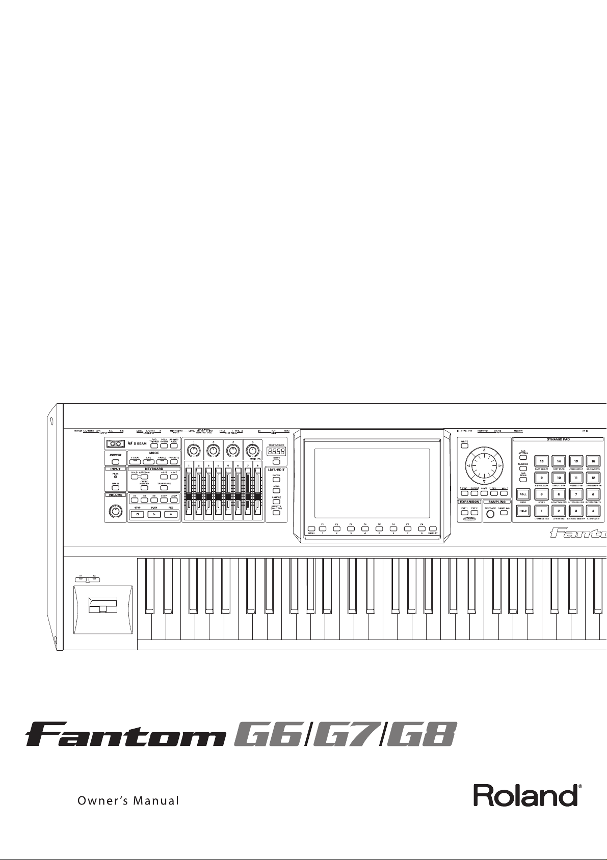
Fantom-G6/G7/G8 Owner’s Manual
201b
Before using this unit, carefully read the sections entitled: “IMPORTANT SAFETY INSTRUCTIONS” (p. 2), “USING THE UNIT
SAFELY” (p. 4), and “IMPORTANT NOTES” (p. 7). These sections provide important information concerning the proper
operation of the unit. Additionally, in order to feel assured that you have gained a good grasp of every feature provided by your
new unit, Owner’s manual should be read in its entirety. The manual should be saved and kept on hand as a convenient
reference.
This Owner’s Manual applies to the Fantom-G6, the Fantom-G7 and the Fantom-G8. The manual uses the term
“Fantom-G” to indicate all these three models.
985
The explanations in this manual include illustrations that depict what should typically be shown by the display. Note, however,
that your unit may incorporate a newer, enhanced version of the system (e.g., includes newer sounds), so what you actually see in
the display may not always match what appears in the manual.
962a
In the interest of product improvement, the specifications and/or appearance of this unit are subject to change without prior
notice.
202
Copyright © 2008 ROLAND CORPORATION
All rights reserved. No part of this publication may be reproduced in any form without the written permission of ROLAND
CORPORATION.
3
Page 4
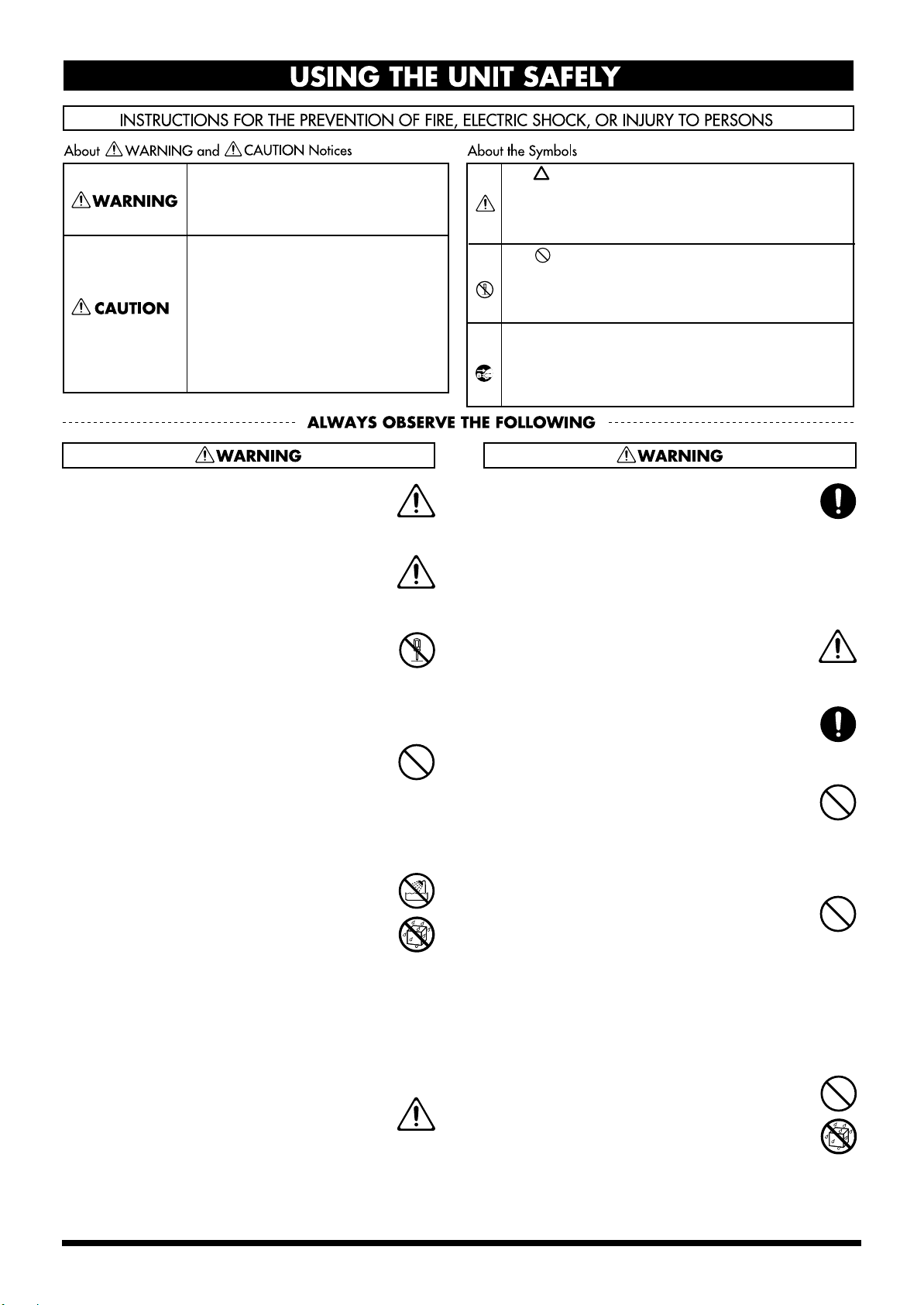
USING THE UNIT SAFELY
Used for instructions intended to alert
the user to the risk of death or severe
injury should the unit be used
improperly.
Used for instructions intended to alert
the user to the risk of injury or material
damage should the unit be used
improperly.
* Material damage refers to damage or
other adverse effects caused with
respect to the home and all its
furnishings, as well to domestic
animals or pets.
001
Before using this unit, make sure to read the
•
instructions below, and the Owner’s Manual.
..........................................................................................................
001-50
Connect mains plug of this model to a mains
•
socket outlet with a protective earthing
connection.
..........................................................................................................
002b
•
Do not open or perform any internal modifications on the unit. (The only exception would be
where this manual provides specific instructions
which should be followed in order to put in place
user-installable options; see p. 308, p. 312.)
..........................................................................................................
003
•
Do not attempt to repair the unit, or replace parts
within it (except when this manual provides
specific instructions directing you to do so). Refer
all servicing to your retailer, the nearest Roland
Service Center, or an authorized Roland
distributor, as listed on the “Information” page.
..........................................................................................................
004
•
Never use or store the unit in places that are:
• Subject to temperature extremes (e.g., direct
sunlight in an enclosed vehicle, near a heating
duct, on top of heat-generating equipment); or
are
• Damp (e.g., baths, washrooms, on wet floors); or are
• Humid; or are
• Exposed to rain; or are
• Dusty; or are
• Subject to high levels of vibration.
..........................................................................................................
005
This unit should be used only with a stand that is
•
recommended by Roland.
The symbol alerts the user to important instructions
or warnings.The specific meaning of the symbol is
determined by the design contained within the
triangle. In the case of the symbol at left, it is used for
general cautions, warnings, or alerts to danger.
The symbol alerts the user to items that must never
be carried out (are forbidden). The specific thing that
must not be done is indicated by the design contained
within the circle. In the case of the symbol at left, it
means that the unit must never be disassembled.
The ● symbol alerts the user to things that must be
carried out. The specific thing that must be done is
indicated by the design contained within the circle. In
the case of the symbol at left, it means that the powercord plug must be unplugged from the outlet.
006
When using the unit with a stand recommended
•
by Roland, the stand must be carefully placed so it
is level and sure to remain stable. If not using a
stand, you still need to make sure that any
location you choose for placing the unit provides
a level surface that will properly support the unit,
and keep it from wobbling.
..........................................................................................................
008a
• The unit should be connected to a power supply
only of the type described in the operating
instructions, or as marked on the unit.
..........................................................................................................
008e
Use only the attached power-supply cord. Also,
•
the supplied power cord must not be used with
any other device.
..........................................................................................................
009
•
Do not excessively twist or bend the power cord,
nor place heavy objects on it. Doing so can
damage the cord, producing severed elements
and short circuits. Damaged cords are fire and
shock hazards!
..........................................................................................................
010
•
This unit, either alone or in combination with an
amplifier and headphones or speakers, may be
capable of producing sound levels that could
cause permanent hearing loss. Do not operate for
a long period of time at a high volume level, or at
a level that is uncomfortable. If you experience
any hearing loss or ringing in the ears, you should
immediately stop using the unit, and consult an
audiologist.
..........................................................................................................
011
• Do not allow any objects (e.g., flammable
material, coins, pins); or liquids of any kind
(water, soft drinks, etc.) to penetrate the unit.
..........................................................................................................
4
..........................................................................................................
Page 5
012a
•
Immediately turn the power off, remove the
power cord from the outlet, and request servicing
by your retailer, the nearest Roland Service
Center, or an authorized Roland distributor, as
listed on the “Information” page when:
• The power-supply cord or the plug has been damaged;
or
• If smoke or unusual odor occurs
• Objects have fallen into, or liquid has been spilled onto
the unit; or
• The unit has been exposed to rain (or otherwise has
become wet); or
• The unit does not appear to operate normally or
exhibits a marked change in performance.
..........................................................................................................
013
•
In households with small children, an adult
should provide supervision until the child is
capable of following all the rules essential for the
safe operation of the unit.
..........................................................................................................
014
• Protect the unit from strong impact.
(Do not drop it!)
..........................................................................................................
015
• Do not force the unit’s power-supply cord to
share an outlet with an unreasonable number of
other devices. Be especially careful when using
extension cords—the total power used by all
devices you have connected to the extension
cord’s outlet must never exceed the power rating
(watts/amperes) for the extension cord. Excessive
loads can cause the insulation on the cord to heat
up and eventually melt through.
..........................................................................................................
016
• Before using the unit in a foreign country, consult
with your retailer, the nearest Roland Service
Center, or an authorized Roland distributor, as
listed on the “Information” page.
..........................................................................................................
022a
Always turn the unit off and unplug the power
•
cord before attempting installation of the circuit
board (ARX series; p. 308, DIMM; p. 312).
..........................................................................................................
023
•
DO NOT play a CD-ROM disc on a conventional
audio CD player. The resulting sound may be of a
level that could cause permanent hearing loss.
Damage to speakers or other system components
may result.
..........................................................................................................
026
•
Do not put anything that contains water (e.g.,
flower vases) on this unit. Also, avoid the use of
insecticides, perfumes, alcohol, nail polish, spray
cans, etc., near the unit. Swiftly wipe away any
liquid that spills on the unit using a dry, soft
cloth.
..........................................................................................................
101a
•
The unit should be located so that its location or
position does not interfere with its proper ventilation.
..........................................................................................................
101c
•
This unit for use only with Roland stand KS-18Z
(Fantom-G6/G7/G8), KS-G8 (Fantom-G8). Use
with other stands (or carts) is capable of resulting
in instability causing possible injury.
..........................................................................................................
102b
Always grasp only the plug on the power-supply
•
cord when plugging into, or unplugging from, an
outlet or this unit.
..........................................................................................................
103a
•
At regular intervals, you should unplug the
power plug and clean it by using a dry cloth to
wipe all dust and other accumulations away from
its prongs. Also, disconnect the power plug from
the power outlet whenever the unit is to remain
unused for an extended period of time. Any
accumulation of dust between the power plug
and the power outlet can result in poor insulation
and lead to fire.
..........................................................................................................
104
•
Try to prevent cords and cables from becoming
entangled. Also, all cords and cables should be
placed so they are out of the reach of children.
..........................................................................................................
106
Never climb on top of, nor place heavy objects on
•
the unit.
..........................................................................................................
107b
• Never handle the power cord or its plugs with
wet hands when plugging into, or unplugging
from, an outlet or this unit.
..........................................................................................................
108d
•
If you need to move the Fantom-G8, take note of
the precautions listed below. At least two persons
are required to safely lift and move the unit. It
should be handled carefully, all the while keeping
it level. Make sure to have a firm grip, to protect
yourself from injury and the instrument from
damage.
• Disconnect the power cord.
• Disconnect all cords coming from external devices.
..........................................................................................................
109a
• Before cleaning the unit, turn off the power and
unplug the power cord from the outlet (p. 25).
..........................................................................................................
110a
•
Whenever you suspect the possibility of lightning
in your area, pull the plug on the power cord out
of the outlet.
..........................................................................................................
115a
Install only the specified circuit board(s) (ARX
•
Series, DIMM). Remove only the specified screws
(p. 308, p. 312).
..........................................................................................................
5
Page 6
118a
•
Should you remove screws from the bottom cover
of the unit (p. 308, p. 312), keep them in a safe
place out of children’s reach, so there is no chance
of them being swallowed accidentally.
..........................................................................................................
120
•
Always turn the phantom power off when
connecting any device other than condenser
microphones that require phantom power. You
risk causing damage if you mistakenly supply
phantom power to dynamic microphones, audio
playback devices, or other devices that don’t
require such power. Be sure to check the specifications of any microphone you intend to use by
referring to the manual that came with it.
(This instrument’s phantom power: 48V DC, 10 mA Max)
..........................................................................................................
6
Page 7

IMPORTANT NOTES
Power Supply
301
• Do not connect this unit to same electrical outlet that is
being used by an electrical appliance that is controlled by
an inverter (such as a refrigerator, washing machine,
microwave oven, or air conditioner), or that contains a
motor. Depending on the way in which the electrical
appliance is used, power supply noise may cause this unit
to malfunction or may produce audible noise. If it is not
practical to use a separate electrical outlet, connect a
power supply noise filter between this unit and the
electrical outlet.
307
• Before connecting this unit to other devices, turn off the
power to all units. This will help prevent malfunctions
and/or damage to speakers or other devices.
308
• Although the LCD and LEDs are switched off when the
POWER switch is switched off, this does not mean that the
unit has been completely disconnected from the source of
power. If you need to turn off the power completely, first
turn off the POWER switch, then unplug the power cord
from the power outlet. For this reason, the outlet into
which you choose to connect the power cord’s plug
should be one that is within easy reach and readily accessible.
Placement
351
• Using the unit near power amplifiers (or other equipment
containing large power transformers) may induce hum.
To alleviate the problem, change the orientation of this
unit; or move it farther away from the source of interference.
352a
• This device may interfere with radio and television
reception. Do not use this device in the vicinity of such
receivers.
352b
• Noise may be produced if wireless communications
devices, such as cell phones, are operated in the vicinity of
this unit. Such noise could occur when receiving or initiating a call, or while conversing. Should you experience
such problems, you should relocate such wireless devices
so they are at a greater distance from this unit, or switch
them off.
354a
• Do not expose the unit to direct sunlight, place it near
devices that radiate heat, leave it inside an enclosed
vehicle, or otherwise subject it to temperature extremes.
Excessive heat can deform or discolor the unit.
355b
• When moved from one location to another where the
temperature and/or humidity is very different, water
droplets (condensation) may form inside the unit. Damage
or malfunction may result if you attempt to use the unit in
this condition. Therefore, before using the unit, you must
allow it to stand for several hours, until the condensation
has completely evaporated.
358
• Do not allow objects to remain on top of the keyboard.
This can be the cause of malfunction, such as keys ceasing
to produce sound.
360
• Depending on the material and temperature of the surface
on which you place the unit, its rubber feet may discolor
or mar the surface.
You can place a piece of felt or cloth under the rubber feet
to prevent this from happening. If you do so, please make
sure that the unit will not slip or move accidentally.
Maintenance
401a
• For everyday cleaning wipe the unit with a soft, dry cloth
or one that has been slightly dampened with water. To
remove stubborn dirt, use a cloth impregnated with a
mild, non-abrasive detergent. Afterwards, be sure to wipe
the unit thoroughly with a soft, dry cloth.
402
• Never use benzine, thinners, alcohol or solvents of any
kind, to avoid the possibility of discoloration and/or
deformation.
Repairs and Data
452
• Please be aware that all data contained in the unit’s
memory may be lost when the unit is sent for repairs.
Important data should always be backed up on a USB
memory, or written down on paper (when possible).
During repairs, due care is taken to avoid the loss of data.
However, in certain cases (such as when circuitry related
to memory itself is out of order), we regret that it may not
be possible to restore the data, and Roland assumes no
liability concerning such loss of data.
Additional Precautions
551
• Please be aware that the contents of memory can be
irretrievably lost as a result of a malfunction, or the
improper operation of the unit. To protect yourself against
the risk of loosing important data, we recommend that
you periodically save a backup copy of important data
you have stored in the unit’s memory on a USB memory.
552
• Unfortunately, it may be impossible to restore the contents
of data that was stored on a USB memory or unit’s
memory once it has been lost. Roland Corporation
assumes no liability concerning such loss of data.
553
• Use a reasonable amount of care when using the unit’s
buttons, sliders, or other controls; and when using its jacks
and connectors. Rough handling can lead to malfunctions.
554
• Never strike or apply strong pressure to the display.
555
• A small amount of noise may be heard from the display
during normal operation.
556
• When connecting / disconnecting all cables, grasp the
connector itself—never pull on the cable. This way you
will avoid causing shorts, or damage to the cable’s
internal elements.
557
• A small amount of heat will radiate from the unit during
normal operation.
7
Page 8
IMPORTANT NOTES
558a
• To avoid disturbing your neighbors, try to keep the unit’s
volume at reasonable levels. You may prefer to use
headphones, so you do not need to be concerned about
those around you (especially when it is late at night).
559a
• When you need to transport the unit, package it in the box
(including padding) that it came in, if possible. Otherwise,
you will need to use equivalent packaging materials.
561
• Use only the specified expression pedal (EV-5; sold
separately). By connecting any other expression pedals,
you risk causing malfunction and/or damage to the unit.
562
• Some connection cables contain resistors. Do not use
cables that incorporate resistors for connecting to this unit.
The use of such cables can cause the sound level to be
extremely low, or impossible to hear. For information on
cable specifications, contact the manufacturer of the cable.
566b
• The sensitivity of the D Beam controller will change
depending on the amount of light in the vicinity of the
unit. If it does not function as you expect, adjust the sensitivity as appropriate for the brightness of your location (p.
291).
• If you switch off the power to an external device that is
connected to the DIGITAL AUDIO IN jack or disconnect
the cable, noise may subsequently be heard in the input
from DIGITAL AUDIO IN. If this occurs, correctly
reconnect the external device, or turn off the Fantom-G’s
[MIX IN] switch.
Handling CD-ROMs
801
• Avoid touching or scratching the shiny underside
(encoded surface) of the disc. Damaged or dirty CD-ROM
discs may not be read properly. Keep your discs clean
using a commercially available CD cleaner.
Copyright
851
• Recording, duplication, distribution, sale, lease, performance, or broadcast of copyrighted material (musical
works, visual works, broadcasts, live performances, etc.)
belonging to a third party in part or in whole without the
permission of the copyright owner is forbidden by law.
852a
• This product can be used to record or duplicate audio or
visual material without being limited by certain technological copy-protection measures. This is due to the fact
that this product is intended to be used for the purpose of
producing original music or video material, and is
therefore designed so that material that does not infringe
copyrights belonging to others (for example, your own
original works) can be recorded or duplicated freely.
853
• Do not use this unit for purposes that could infringe on a
copyright held by a third party. We assume no responsibility whatsoever with regard to any infringements of
third-party copyrights arising through your use of this
unit.
Before Using Cards
Using USB memory
704
• Carefully insert the USB memory all the way in—until it is
firmly in place.
705
• Never touch the terminals of the USB memory. Also,
avoid getting the terminals dirty.
708
• USB memorys are constructed using precision components; handle the cards carefully, paying particular note to
the following.
• To prevent damage to the cards from static electricity,
be sure to discharge any static electricity from your
own body before handling the cards.
• Do not touch or allow metal to come into contact with
the contact portion of the cards.
• Do not bend, drop, or subject cards to strong shock or
vibration.
• Do not keep cards in direct sunlight, in closed vehicles,
or other such locations (storage temperature: -25 to 85˚
C).
• Do not allow cards to become wet.
• Do not disassemble or modify the cards.
* MMP (Moore Microprocessor Portfolio) refers to a patent
portfolio concerned with microprocessor architecture,
which was developed by Technology Properties Limited
(TPL). Roland has licensed this technology from the TPL
Group.
add
MatrixQuest™ 2008 TEPCO UQUEST,
*
LTD. All rights reserved.
The Fantom-G’s USB functionality uses
MatrixQuest middleware technology
from TEPCO UQUEST, LTD.
add
* Harpsichord samples courtesy of the Hamamatsu
Museum of Musical Instruments.
204
* Microsoft and Windows are registered trademarks of
Microsoft Corporation.
206j
* Windows® is known officially as: “Microsoft® Windows®
operating system.”
207
* Apple and Macintosh are registered trademarks of Apple
Inc.
209
* Mac OS is a trademark of Apple Inc.
8
Page 9

Contents
USING THE UNIT SAFELY......................................................................................... 4
IMPORTANT NOTES ..................................................................................................7
Contents......................................................................................................................9
01: Introduction (Overview and Basic Operation) ... 19
Main Features........................................................................................................... 20
Panel Descriptions................................................................................................... 22
Front Panel............................................................................................................................................................................. 22
Rear Panel ..............................................................................................................................................................................24
Making Connections................................................................................................ 25
Connecting an Amp and Speaker System......................................................................................................................... 25
Connecting a USB Mouse (sold separately)...................................................................................................................... 26
Placing the Fantom-G on a Stand....................................................................................................................................... 27
Turning On the Power..............................................................................................28
Turning Off the Power......................................................................................................................................................... 28
Listening to the Demo Songs .................................................................................29
Song Automatically Loaded at Power-on (When Loading a Project)............................................................. 29
Various Performance Features............................................................................... 30
Velocity/Aftertouch............................................................................................................................................... 30
Pitch Bend/Modulation Lever .............................................................................................................................30
Octave Shift (OCT) .................................................................................................................................................30
Transpose................................................................................................................................................................. 30
Hold Pedal............................................................................................................................................................... 31
Control Pedal...........................................................................................................................................................31
Overview of the Fantom-G ......................................................................................32
How the Fantom-G is Organized .......................................................................................................................................32
Basic Structure......................................................................................................................................................... 32
Different Units of Sound .......................................................................................................................................32
Single / Live / Studio Modes...............................................................................................................................33
About Polyphony ...................................................................................................................................................34
About Memory...................................................................................................................................................................... 35
About the Internal Effects.................................................................................................................................................... 36
Types of Effects....................................................................................................................................................... 36
About the Sequencer ............................................................................................................................................................36
Audio and MIDI .....................................................................................................................................................36
What is a Song?....................................................................................................................................................... 36
What is a Track?...................................................................................................................................................... 37
Songs and the State of the Sound Generator ......................................................................................................37
SMF (Standard MIDI File .MID)........................................................................................................................... 37
About the Sampling Section................................................................................................................................................ 38
Basic Operation of the Fantom-G...........................................................................39
Switching the Sound Generator Mode ..............................................................................................................................39
How the Function Buttons Work .......................................................................................................................................40
Moving the Cursor ...............................................................................................................................................................40
Editing a Value...................................................................................................................................................................... 41
Assigning a Name ................................................................................................................................................................42
Basic Pad Operations............................................................................................................................................................43
Switching the Pad Mode........................................................................................................................................ 43
Viewing the Pad Settings....................................................................................................................................... 43
Using the Pads as Numeric Keys .........................................................................................................................43
Shortcut Menu....................................................................................................................................................................... 44
9
Page 10

Contents
02: Sound Generator, Section 1 (Playing Sounds) ...45
Playing in Single Mode............................................................................................ 46
About the Single Play Screen .............................................................................................................................................. 46
Displaying Single Play Screen ..............................................................................................................................46
Selecting a Patch ...................................................................................................................................................................47
Selecting Patches by Category (Patch Finder)....................................................................................................48
Selecting Patches from the List............................................................................................................................. 49
Auditioning Patches (Phrase Preview)................................................................................................................ 49
Selecting the Tones That Will Sound (Tone On/Off)......................................................................................................50
Playing Single Notes (Monophonic).................................................................................................................................. 50
Part Settings (Part View)...................................................................................................................................................... 51
Selecting the Parameter Controlled by the Realtime Controllers or D Beam Controller (Control Setting) ............51
Controller Reset ....................................................................................................................................................................51
Playing Percussion Instruments (Rhythm Set)................................................................................................................. 52
Selecting a Rhythm Set ..........................................................................................................................................52
Playing a Sample Set ............................................................................................................................................................53
Selecting a Sample Set............................................................................................................................................ 53
Creating a List of Frequently Used Sounds (Favorite).........................................54
Registering a Sound (Regist)................................................................................................................................. 54
Recalling a Sound ...................................................................................................................................................54
Specifying the Volume for Each Step (Favorite Level) .....................................................................................55
Changing the Step in Which You Registered a Sound...................................................................................... 55
Removing a Sound You Registered (Remove)................................................................................................... 55
Removing All Sound Registrations from a Bank (Remove Bank)...................................................................55
Registering a Song (Set Song) ...............................................................................................................................56
Importing a Text File (Import Text)..................................................................................................................... 56
Removing a Text File (Remove Text)................................................................................................................... 57
Switching the Display Font (Font) .......................................................................................................................57
Playing in Live Mode................................................................................................58
Displaying Live Play (Layer/Split) Screen ....................................................................................................................... 58
Functions in the Live Play (Layer/Split) Screen ..............................................................................................................59
Selecting a Live Set ...............................................................................................................................................................60
Selecting Live Sets from the List........................................................................................................................... 60
Using the Live Play (Layer/Split) Screen..........................................................................................................................61
Selecting a Part........................................................................................................................................................61
Selecting the Part that You want to Sound (Keyboard Switch)....................................................................... 61
Selecting the Part Played by the Pads.................................................................................................................. 61
Selecting the Sound for a Part............................................................................................................................... 61
Combining and Playing Sounds Together (Layer)............................................................................................62
Playing Different Sounds in Different Areas of the Keyboard (Split) ............................................................62
Using the Live Set Part Mixer Screen................................................................................................................................. 63
Editing the Part Settings ........................................................................................................................................ 63
Using the Layer Edit Screen................................................................................................................................................ 64
Selecting the Sound for a Part............................................................................................................................... 64
Editing the Part Settings ........................................................................................................................................ 64
Performing with the Arpeggio ...........................................................................................................................................65
Performing with the Realtime Controllers and D Beam Controller.............................................................................. 65
Setting Effects........................................................................................................................................................................ 65
Adjusting the Master Level................................................................................................................................................. 65
Making Detailed Settings for a Live Set ............................................................................................................................65
Playing in Studio Mode............................................................................................66
Displaying Studio Play Screen............................................................................................................................................ 66
Functions in the Studio Play Screen................................................................................................................................... 67
Switching the Displayed Part Group................................................................................................................... 67
Selecting a Studio Set ...........................................................................................................................................................67
Selecting Studio Sets from the List....................................................................................................................... 68
Using the Studio Play Screen .............................................................................................................................................. 68
Selecting a Part........................................................................................................................................................68
Selecting the Sound for a Part............................................................................................................................... 68
Selecting the Part that You Want to Sound (Keyboard Switch) ......................................................................69
Editing the Part Settings ........................................................................................................................................ 69
Performing with the Arpeggio ...........................................................................................................................................70
Performing with the Realtime Controllers and D Beam Controller.............................................................................. 70
Setting Effects........................................................................................................................................................................ 70
Adjusting the Master Level................................................................................................................................................. 70
Making Detailed Settings for a Studio Set ........................................................................................................................70
10
Page 11

Contents
03: Sound Generator, Section 2 (Controlling Sounds)... 71
Modifying the Sound in Real Time .........................................................................72
Waving Your Hand Over the D Beam to Modify the Sound (D Beam Controller) ....................................................72
Making Settings for the D Beam Controller .......................................................................................................73
Using Knobs, Sliders or S1/S2 Buttons to Modify the Sound (Realtime Controller).................................................75
Changing Realtime Controller Settings............................................................................................................... 76
Using a Pedal to Modify the Sound (Control Pedal)....................................................................................................... 77
Making Control Pedal Settings............................................................................................................................. 77
Playing Arpeggios....................................................................................................78
About Arpeggio ....................................................................................................................................................................78
Playing Arpeggios ................................................................................................................................................................78
Turning Arpeggio On and Off.............................................................................................................................. 78
Determining the Tempo for Arpeggio Performances .......................................................................................78
Holding an Arpeggio............................................................................................................................................. 78
Arpeggio Settings .................................................................................................................................................................78
Importing SMF or Phrases to an Arpeggio Style ............................................................................................... 79
Saving the Arpeggio You Have Created (Write) .............................................................................................................80
Using the Chord Memory Function (Chord Memory) ...........................................81
About the Chord Memory Function .................................................................................................................................. 81
Performing with the Chord Memory Function................................................................................................................ 81
Turning Chord Memory Function On and Off ..................................................................................................81
Selecting Chord Forms........................................................................................................................................... 81
Sounding a Chord in the Order of Its Notes (Rolled Chord)........................................................................... 82
Creating Your Own Chord Forms...................................................................................................................................... 82
Saving the Chord Forms You Have Created ....................................................................................................................82
04: Sound Generator, Section 3 (Creating Sounds).. 83
Creating a Patch.......................................................................................................84
How to Make Patch Settings............................................................................................................................................... 84
Editing a Patch Quickly (Patch Zoom Edit)........................................................................................................ 84
Editing All Parameters of a Patch (Patch Pro Edit) ...........................................................................................86
Initializing Patch/Tone Settings (Patch Initialize/Tone Initialize)................................................................. 87
Copying Patch (Tone) Settings (Patch Tone Copy) ...........................................................................................87
Cautions When Selecting a Waveform................................................................................................................88
Saving Patches You’ve Created (Write).............................................................................................................................88
Auditioning the Save-Destination Patch (Compare)......................................................................................... 89
Functions of Patch Parameters............................................................................................................................................89
Settings Common to the Entire Patch (General) ................................................................................................89
Modifying Waveforms (Wave).............................................................................................................................91
Changing How a Tone Is Sounded (TMT).......................................................................................................... 92
Modifying Pitch (Pitch/Pitch Env) ...................................................................................................................... 96
Modifying the Brightness of a Sound with a Filter (TVF/TVF Env) ..............................................................98
Adjusting the Volume (TVA/TVA Env)........................................................................................................... 100
Output.................................................................................................................................................................... 102
Modulating Sounds (LFO1/2/Step LFO)......................................................................................................... 102
Apply Portamento or Legato to the Sound (Solo/Porta) ...............................................................................105
Miscellaneous Settings (Misc)............................................................................................................................. 107
Matrix Control Settings (Control 1–4) ...............................................................................................................109
Setting Effects for a Patch (PFX)......................................................................................................................... 111
Creating a Rhythm Set...........................................................................................112
How to Make Rhythm Set Settings ..................................................................................................................................112
Editing a Rhythm Set Quickly (Patch Zoom Edit)........................................................................................... 112
Editing All Parameters (Patch Pro Edit)............................................................................................................ 114
Initializing Rhythm Set/Key Settings (Rhythm Set Initialize/Rhythm Key Initialize) .............................115
Copying Rhythm Tone Settings (Rhythm Tone Copy)................................................................................... 115
Cautions When Selecting a Waveform..............................................................................................................116
Saving Rhythm Sets You’ve Created (Write)..................................................................................................................116
Auditioning the Save-Destination Rhythm Set (Compare)............................................................................ 117
Functions of Rhythm Set Parameters............................................................................................................................... 117
Making Settings Common to the Entire Rhythm Set (General)..................................................................... 117
Modifying Waveforms (Wave)...........................................................................................................................119
Changing How a Rhythm Tone Is Sounded (WMT)....................................................................................... 120
Modifying Pitch (Pitch/Pitch Env) .................................................................................................................... 121
11
Page 12

Contents
Modifying the Brightness of a Sound with a Filter (TVF/TVF Env) ............................................................122
Adjusting the Volume (TVA/TVA Env)........................................................................................................... 124
Output Settings (Output) ....................................................................................................................................125
Setting Effects for a Rhythm Set (PFX) .............................................................................................................. 125
Creating a Sample Set ........................................................................................... 126
How to make Sample Set settings .................................................................................................................................... 126
Editing a Sample Set Quickly (Patch Zoom Edit)............................................................................................ 126
Editing All Parameters (Patch Pro Edit)............................................................................................................ 127
Initializing Sample Set Settings (Sample Set Initialize)................................................................................... 127
Saving Sample Sets You’ve Created (Write)...................................................................................................................128
Functions of Sample Set Parameters................................................................................................................................129
Making Settings Common to the Entire Sample Set (General)......................................................................129
Modifying Waveforms (Wave)...........................................................................................................................130
Modifying Pitch (Pitch)........................................................................................................................................ 130
Adjusting the Volume (Amp)............................................................................................................................. 131
Output Settings (Output) ....................................................................................................................................131
Setting Effects for a Sample Set (PFX) ...............................................................................................................131
Creating a Live/Studio Set.....................................................................................132
Common Settings (Utility) ................................................................................................................................................132
NAME ....................................................................................................................................................................132
Part Info..................................................................................................................................................................132
Part Settings (Part View).................................................................................................................................................... 133
Level/Pan (When the Part Group is Internal/EXP1/EXP2).......................................................................... 134
Level/Pan (When the Part Group is External)................................................................................................. 135
Key Range..............................................................................................................................................................135
Output/EFX ..........................................................................................................................................................136
Pitch........................................................................................................................................................................ 137
Scale Tune.............................................................................................................................................................. 138
Vibrato.................................................................................................................................................................... 139
Offset ......................................................................................................................................................................139
Mono/Poly/Legato.............................................................................................................................................. 140
Voice Reserve ........................................................................................................................................................ 141
MIDI Rx Filter .......................................................................................................................................................141
Selecting the Parameter Controlled by the Realtime Controllers or D Beam Controller (Control Setting) ..........142
Keyboard Mode ....................................................................................................................................................143
D Beam................................................................................................................................................................... 143
Knob .......................................................................................................................................................................145
Slider....................................................................................................................................................................... 145
Switch S1/S2 .........................................................................................................................................................146
Arpeggio ................................................................................................................................................................146
Chord Memory .....................................................................................................................................................146
Dynamic Pad......................................................................................................................................................... 146
Ctrl Switch ............................................................................................................................................................. 147
Changing the Settings of the Patch Assigned to a Part................................................................................................. 147
Initializing Live/Studio Set Settings (Init)......................................................................................................................148
Saving a Live/Studio Set You’ve Created (Write).........................................................................................................148
Adding Effects........................................................................................................150
Where Effect Settings are Saved ....................................................................................................................................... 150
Turning Effects On and Off...............................................................................................................................................150
Making Effect Settings .......................................................................................................................................................151
Applying Effects in Single Mode...................................................................................................................................... 151
Applying Effects in Live Mode......................................................................................................................................... 151
Specifying How the Sound will be Output (Routing)..................................................................................... 151
Signal Flow Diagram and Parameters...............................................................................................................152
Applying Effects in Studio Mode..................................................................................................................................... 154
Specifying How the Sound Will Be Output (Routing).................................................................................... 154
Signal Flow Diagram and Parameters...............................................................................................................154
Making Patch Multi-Effects Settings (PFX)..................................................................................................................... 157
Making Multi-Effects Settings (MFX1–2) ........................................................................................................................ 158
Making Chorus Settings (Chorus).................................................................................................................................... 159
Making Reverb Settings (Reverb)..................................................................................................................................... 159
Mastering Effect .................................................................................................................................................................. 160
Effects List..............................................................................................................161
MFX/PFX Parameter..........................................................................................................................................................161
Chorus Parameters .............................................................................................................................................................184
Reverb Parameters.............................................................................................................................................................. 185
Input Effect Parameters .....................................................................................................................................................186
12
Page 13

Contents
05: Pads (Using the Pads)..................................... 187
Using the Pads ....................................................................................................... 188
Common Operations for Pads ..........................................................................................................................................188
Switching the Pad Mode (PAD MODE)............................................................................................................188
Using the Pads as Numeric Keys (NUMERIC) ................................................................................................ 188
Using the Hold Function to Sustain the Sounds (HOLD) ..............................................................................188
Using the Roll Function (ROLL)......................................................................................................................... 189
Switching Banks (BANK) ....................................................................................................................................189
Editing the Pad Settings (PAD SETTING)........................................................................................................ 190
Exchanging Pads (Pad Exchange)...................................................................................................................... 190
1 SAMPLE PAD (Using the Pads to Play Samples).......................................................................................................191
About Samples...................................................................................................................................................... 191
Editing the Pad Settings.......................................................................................................................................191
2 RHYTHM (Using the Pads to Play a Rhythm Set)...................................................................................................... 192
Editing the Pad Settings.......................................................................................................................................192
3 CHORD MEMORY (Using the Pads to Switch Chord Forms) .................................................................................193
Editing the Pad Settings.......................................................................................................................................193
4 ARPEGGIO (Using the Pads to Switch Arpeggio Styles).......................................................................................... 193
Editing the Pad Settings.......................................................................................................................................193
5 RPS (Using the Pads to Play Phrases)........................................................................................................................... 194
Specifying the Tempo for Phrase Playback ......................................................................................................194
Editing the Pad Settings.......................................................................................................................................194
6 RHYTHM PTN (Using the Pads to Play Rhythm Patterns) ......................................................................................196
Specifying the Tempo for Rhythm Pattern Playback...................................................................................... 196
Editing the Pad Settings.......................................................................................................................................196
7 TONE SEL/SW (Using the Pads to Select Tones or Switch Them On/Off) ........................................................... 197
Checking the Pad Status...................................................................................................................................... 197
8 TRACK MUTE (Using the Pads to Mute Tracks)........................................................................................................197
Checking the Pad Status...................................................................................................................................... 197
9 BOOKMARK (Using the Pads to Recall Frequently Used Screens).........................................................................198
Registering a Screen .............................................................................................................................................198
Recalling a Screen................................................................................................................................................. 198
10 MIDI TX SW (Using the Pads to Turn External MIDI Transmit Channels (1–16) On/Off) ...............................198
Checking the Pad Status...................................................................................................................................... 198
11 EFFECT SW (Using the Pads to Switch the Effects) .................................................................................................199
Checking the Pad Status...................................................................................................................................... 199
12 PATCH MFX SW (Using the Pads to Switch Patch Multi-effects) .........................................................................199
Checking the Pad Status...................................................................................................................................... 199
13 PART SELECT (Using the Pads to Select Parts)........................................................................................................200
Checking the Pad Status...................................................................................................................................... 200
14 PART MUTE (Using the Pads to Mute Parts)............................................................................................................ 200
Checking the Pad Status...................................................................................................................................... 200
15 USER GROUP (Using the Pads to Register/Recall User Groups)..........................................................................201
Recalling a User Group Sound ...........................................................................................................................201
Registering a Sound in a User Group................................................................................................................ 201
16 FAVORITE (Using the Pads to Register/Recall Favorite Settings)........................................................................202
Recalling a Favorite Sound (Setting)..................................................................................................................202
Registering a Favorite Sound (Setting).............................................................................................................. 202
13
Page 14

Contents
06: Sequencer (Creating a Song) ..........................203
Playing Back a Song.............................................................................................. 204
Three Ways to Play Back .....................................................................................................................................204
Playing a Song (Song Play)................................................................................................................................................204
Loading a Song (Song List) .................................................................................................................................204
Playing a Song (Song Play) .................................................................................................................................205
Operations in the Song Play Screen................................................................................................................... 205
Selecting a Sound (Part or Patch) in the Song Screen...................................................................................... 206
Fast-forwarding or Rewinding during Playback............................................................................................. 206
Muting the Playback of a Track (MUTE) ..........................................................................................................206
Accessing the Mixer Screen................................................................................................................................. 207
Changing the Playback Tempo of the Song...................................................................................................... 207
Playing a Song Repeatedly (Loop).....................................................................................................................208
Placing Markers in a Song (Marker) .................................................................................................................. 208
Changing the Track Display Zoom and Display Order (Zoom/Track Order) ...........................................209
Naming a Track (Track Name)........................................................................................................................... 209
Specifying a Track’s Output Destination (Output Assign) ............................................................................210
Deleting a Song File (Song Delete)..................................................................................................................... 210
Song Automatically Loaded at Power-on (When Loading a Project)........................................................... 210
Erasing the Currently-open Song (Song Clear)................................................................................................ 211
Playing a Standard MIDI File (SMF)................................................................................................................................ 212
Copying a Standard MIDI File (SMF) from Your Computer to the Fantom-G........................................... 212
Playing a Standard MIDI File (SMF) (SMF List) .............................................................................................. 212
Importing an SMF into a Phrase (Import Phrase)............................................................................................ 213
Importing an SMF into a Song (Import Song)..................................................................................................213
Playing Phrases (MIDI Phrase).........................................................................................................................................214
Auditioning a Phrase (MIDI Phrase List)..........................................................................................................214
Loading a Phrase (Load)...................................................................................................................................... 214
Deleting a Phrase from the Project (Delete Phrase)......................................................................................... 215
Duplicating a Phrase (Duplicate) .......................................................................................................................215
Saving a Phrase (Save) ......................................................................................................................................... 216
Saving all Phrases (Save All)............................................................................................................................... 216
Recording MIDI.......................................................................................................217
Phrases and Songs ................................................................................................................................................ 217
Two Methods of Recording................................................................................................................................. 217
Undo function .....................................................................................................................................................................217
Recording into a Song ........................................................................................................................................................ 218
Selecting a Sound for Recording ........................................................................................................................218
Erasing the Song/Phrases from the Temporary Area (Song Clear)..............................................................218
Specifying the Time Signature (Beat Track) .....................................................................................................219
Specifying the Tempo ..........................................................................................................................................219
Selecting a MIDI Track and the Recording-start Measure .............................................................................219
Recording into a Phrase..................................................................................................................................................... 220
Selecting a Sound for Recording ........................................................................................................................220
Specifying the Tempo ..........................................................................................................................................220
Selecting the Phrase to Record............................................................................................................................ 221
Recording Your Performance Just as You Play It (Realtime Recording).................................................................... 222
Auto Track Function ............................................................................................................................................222
Basic Procedure for Realtime Recording........................................................................................................... 222
Realtime Rec Standby Parameters .....................................................................................................................223
Selecting the Sequencer Data that will Be Recorded (Recording Select)......................................................224
Erasing Unwanted Data While You Record (Realtime Erase)....................................................................... 225
Auditioning Sounds or Phrases While Recording (Rehearsal Function) .....................................................225
Inputting Data One Step at a Time (Step Recording)....................................................................................................226
Entering Notes and Rests ....................................................................................................................................226
Recording Audio .................................................................................................... 228
Samples and Songs............................................................................................................................................... 228
Recording into a Song ........................................................................................................................................................ 228
Selecting an Audio Track and the Recording-start Measure .........................................................................229
Audio Recording................................................................................................................................................................. 230
Basic Procedure for Audio Recording............................................................................................................... 230
Audio Rec Standby Parameters.......................................................................................................................... 231
14
Page 15

Contents
Editing Songs......................................................................................................... 232
Three Ways to Edit............................................................................................................................................... 232
Editing a Song (Song Edit) ................................................................................................................................................232
Opening the Song Edit Screen ............................................................................................................................232
Moving a Sample/Phrase (Move)...................................................................................................................... 233
Inserting a Sample/Phrase at a Specified Location (Insert)........................................................................... 233
Deleting a Sample/Phrase from a Track (Delete)............................................................................................234
Copying a Sample/Phrase (Copy).....................................................................................................................234
Editing a Sample/Phrase (Edit) .........................................................................................................................234
Song Utility (Song Util)...................................................................................................................................................... 235
Changing the Track Display Zoom and Display Order (Zoom/Track Order) ...........................................235
Erasing the Currently-open Song (Song Clear)................................................................................................ 235
Clearing a Track (Track Clear)............................................................................................................................ 235
Naming a Track (Track Name)........................................................................................................................... 235
Changing the Tempo during the Song (Tempo Track)...................................................................................235
Changing the Time Signature during the Song (Beat Track) ......................................................................... 236
Track Edit Function ............................................................................................................................................................ 237
Inserting Blank Measures into a Track (Track Edit Insert)............................................................................. 237
Deleting Unwanted Measures from a Track (Track Edit Delete) ..................................................................237
Copying Measures of a Track (Track Edit Copy) ............................................................................................237
Editing a Phrase (Phrase Edit) ..........................................................................................................................................238
Opening the Phrase Edit Screen......................................................................................................................... 238
Playing a Phrase (Play) ........................................................................................................................................ 238
Erasing the Currently-edited Phrase (Clear) .................................................................................................... 239
Saving a Phrase (Save) ......................................................................................................................................... 239
Specifying the Time Signature of a Phrase (Phrase Beat)............................................................................... 239
Phrase Modify Menu.......................................................................................................................................................... 239
Aligning a Phrase’s Timing (Quantize)............................................................................................................. 240
Erasing Unwanted Performance Data (Erase).................................................................................................. 242
Deleting Unwanted Measures (Delete) .............................................................................................................243
Copying Phrases (Copy)...................................................................................................................................... 243
Inserting a Blank Measure (Insert).....................................................................................................................244
Transpose the Key (Transpose) ..........................................................................................................................244
Changing the Velocity (Change Velocity).........................................................................................................245
Changing the MIDI Channel (Change Channel) .............................................................................................246
Modifying the Length of Notes (Change Duration)........................................................................................ 247
Shifting Performance Data Forward and Back (Shift Clock)..........................................................................248
Thinning Out the Sequencer Data (Data Thin) ................................................................................................249
Deleting Blank Measures (Truncate) .................................................................................................................249
Editing Individual Items of Sequencer Data (Microscope) ..........................................................................................250
Editing Sequencer Data (Basic Procedure in the Microscope)....................................................................... 250
Sequencer Data Handled by Phrases................................................................................................................. 251
Viewing Sequencer Data (View) ........................................................................................................................252
Inserting Sequencer Data (Create) .....................................................................................................................252
Erasing Sequencer Data (Erase).......................................................................................................................... 252
Moving Sequencer Data (Move)......................................................................................................................... 253
Copying Sequencer Data (Copy)........................................................................................................................ 253
Saving a Song (Song Save)...................................................................................254
What the Saved Song Data Contains................................................................................................................. 254
What is Saved at the Same Time as the Song ...................................................................................................254
Saving a Song (Save) ..........................................................................................................................................................254
Resampling the Contents of All Tracks to a Single Sample .........................................................................................255
Copying a Resampled Sample to Your Computer to Create a CD or MP3 .................................................255
Save As an SMF File (Save As SMF) ................................................................................................................................256
15
Page 16

Contents
07: Sampler ......................................................... 257
Sampling................................................................................................................. 258
Switching External Input On/Off ....................................................................................................................................258
Making Input Source Settings (Input Setting)................................................................................................................258
Functions of Input Setting Parameters ............................................................................................................................258
Input Effect Setup Settings ................................................................................................................................................ 259
Sampling Procedure........................................................................................................................................................... 260
Dividing a Sample During Sampling ................................................................................................................262
Sampling Earlier in Time (Skip Back Sampling)............................................................................................................ 262
Editing a Sample .................................................................................................... 263
Selecting a Sample (Sample List)...................................................................................................................................... 263
Selecting a Sample................................................................................................................................................ 263
Loading a Sample (Load) ....................................................................................................................................264
Loading All Samples (Load All).........................................................................................................................264
Unloading a Sample (Unload)............................................................................................................................ 264
Deleting a Sample (Delete)..................................................................................................................................265
Importing an Audio File (WAV/AIFF) from Your Computer ......................................................................265
Displaying Sample Edit Screen (Sample Edit)................................................................................................................266
Magnifying/Shrinking the Waveform Display (Zoom) ................................................................................. 266
Setting the Start/End Points of the Sample .................................................................................................................... 267
Using the Knobs to Edit the Points ....................................................................................................................267
Making Settings for Sample (Sample Parameters).........................................................................................................268
Sample BPM calculation function ....................................................................................................................................269
Removing Unwanted Portions of a Sample (Truncate) ................................................................................................269
Boosting or Limiting the High-frequency Range of the Sample (Emphasis)............................................................. 269
Maximizing the Volume of a Sample (Normalize)........................................................................................................ 270
Amp ...................................................................................................................................................................................... 270
Stretching or Shrinking a Sample (Time Stretch)...........................................................................................................271
Dividing a Sample into Notes (Chop) .............................................................................................................................272
Saving a Sample (Save)...................................................................................................................................................... 274
Saving all samples (Save All)............................................................................................................................................ 274
Multisample ............................................................................................................275
Creating a multisample...................................................................................................................................................... 275
Creating a multisample in the Patch Edit screen............................................................................................. 275
Editing a multisample........................................................................................................................................................276
About the Multisample Edit screen ...................................................................................................................276
Selecting the notes to edit....................................................................................................................................277
Changing the multisample assigned to a tone (List).......................................................................................277
Erasing the data from the selected region of notes (Erase) ............................................................................277
Assigning a sample to the selected region (Assign)........................................................................................ 277
Copying a sample from a key to another key (Copy) .....................................................................................277
Opening the Tone Switch/Select window (Tone Sw/Sel) ............................................................................. 277
Moving the split point (Split Point) ...................................................................................................................277
Returning a multisample to the last-written state (Reload) ........................................................................... 277
Erasing all notes (Erase All) ................................................................................................................................ 278
Replacing the sample of the current zone (Sample Select)............................................................................. 278
Specify the original key (Original Key) of the sample ....................................................................................278
Sorting samples in the order of their original key (Sort) ................................................................................278
Moving all samples to left or right (Shift).........................................................................................................278
Moving the data of the current zone to left or right (Move).......................................................................... 278
16
Page 17

Contents
08: Various Settings (Menu and System)............... 279
Menu Reference .....................................................................................................280
Menus................................................................................................................................................................................... 280
Project-related Settings (Project)....................................................................................................................................... 280
Load Project...........................................................................................................................................................280
Save Project............................................................................................................................................................ 281
Save As Project......................................................................................................................................................281
Create Project ........................................................................................................................................................282
Backup Project....................................................................................................................................................... 282
Restore Project....................................................................................................................................................... 283
System Settings (System)................................................................................................................................................... 283
Reset to Default Factory Settings (Factory Reset) ..........................................................................................................284
Format USB Memory..........................................................................................................................................................284
Exchanging Files with Your Computer (USB Storage) .................................................................................................285
Connections........................................................................................................................................................... 285
Specify the Connection-Destination ..................................................................................................................285
Cautions Regarding Folders and Files ..............................................................................................................286
Exiting Storage Mode........................................................................................................................................... 286
Examples of Using Storage Mode ...................................................................................................................... 287
Import Audio.......................................................................................................................................................................289
System Settings (Settings Common to All Modes).............................................290
How to Make System Function Settings .........................................................................................................................290
Saving the System Settings (System Write) ....................................................................................................................290
Functions of System Parameters....................................................................................................................................... 291
Pedal/D Beam....................................................................................................................................................... 291
Keyboard................................................................................................................................................................ 292
Dynamic Pad......................................................................................................................................................... 292
Knob/Slider........................................................................................................................................................... 293
Magic Control........................................................................................................................................................294
Switch S1/S2 .........................................................................................................................................................294
Sync/Temp............................................................................................................................................................295
Metronome ............................................................................................................................................................297
Sound...................................................................................................................................................................... 297
MIDI .......................................................................................................................................................................299
USB .........................................................................................................................................................................300
Scale Tune.............................................................................................................................................................. 300
Preview ..................................................................................................................................................................300
System Ctrl ............................................................................................................................................................301
Screen Saver........................................................................................................................................................... 301
Input/Sampling....................................................................................................................................................301
Startup.................................................................................................................................................................... 302
System Information (Info) .................................................................................................................................................302
Changing the Wallpaper (Wallpaper) .............................................................................................................................303
Importing an Image as Wallpaper (Import) .....................................................................................................303
Delete Wallpaper .................................................................................................................................................. 303
Display-related Settings (Appearance)............................................................................................................................ 304
About V-LINK..........................................................................................................305
What is V-LINK?................................................................................................................................................................. 305
Connection Examples......................................................................................................................................................... 305
Turning the V-LINK ON/OFF .........................................................................................................................................305
V-LINK Settings..................................................................................................................................................................305
V-LINK Parameters..............................................................................................................................................306
Resetting the Image.............................................................................................................................................. 306
17
Page 18

Contents
09: Appendix....................................................... 307
Installing the Expansion Board ............................................................................308
Cautions When Installing an Expansion Board .............................................................................................................308
How to Install an Expansion Board .................................................................................................................................308
Removing an Expansion Board ........................................................................................................................................309
Configuring the Newly-installed Expansion Board ...................................................................................................... 309
Installation de la carte d’expansion Wave........................................................... 310
Précautions à prendre lors de l’installation d’une carte d’expansion Wave.............................................................. 310
Installation d’une carte d’expansion Wave..................................................................................................................... 310
Retrait d’une carte d’expansion........................................................................................................................................311
Configuration de la carte d’expansion installée............................................................................................................. 311
Expanding the DIMM Memory............................................................................... 312
Precautions for Expanding Memory................................................................................................................................ 312
How to Expand the Memory ............................................................................................................................................312
Removing the Memory........................................................................................................................................ 313
Checking that Memory is Installed Correctly ................................................................................................................313
Ajouter de la mémoire ...........................................................................................314
Précautions à prendre lors de l’ajout de mémoire......................................................................................................... 314
Installation du module de mémoire.................................................................................................................................314
Retrait du module de mémoire ..........................................................................................................................315
Troubleshooting.....................................................................................................316
Problems Concerning the Entire Fantom-G .....................................................................................................316
Issues Related to Sound.......................................................................................................................................316
Issues Related to Effects....................................................................................................................................... 318
Issues Related to Saving Data.............................................................................................................................318
Issues Related to Sequencer ................................................................................................................................319
Issues Related to MIDI and External Devices ..................................................................................................320
Issues Related to Sampling .................................................................................................................................320
Issues Related to a USB memory........................................................................................................................ 321
Issues Related to a USB connection ...................................................................................................................321
Error Messages ...................................................................................................... 322
About MIDI .............................................................................................................. 323
About MIDI Connectors ...................................................................................................................................... 323
MIDI Channels and Multi-timbral Sound Generators.................................................................................... 323
Specifications......................................................................................................... 326
Index........................................................................................................................ 328
18
Page 19
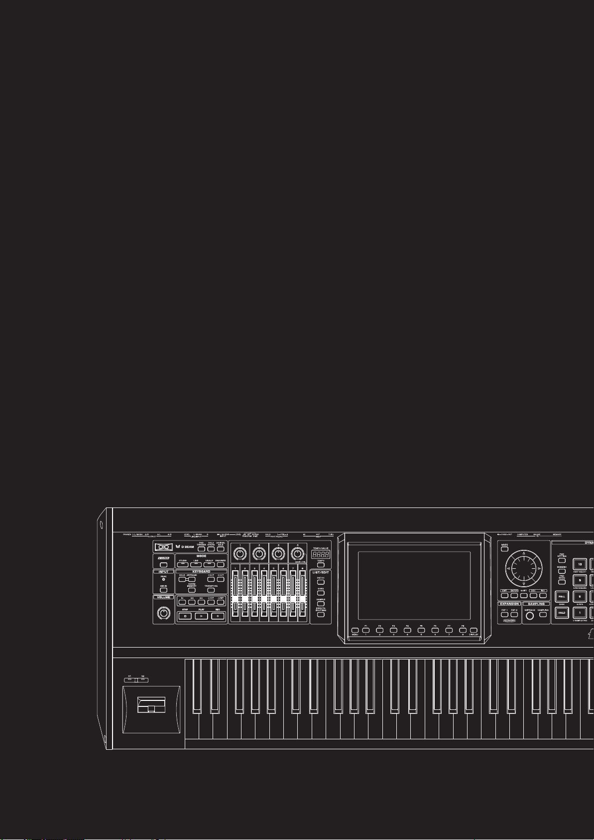
01: Introduction
This chapter explains the Fantom-G’s panels, provides an overview of the instrument,
and explains basic operation.
• Main Features ............................................................p. 20
• Panel Descriptions.......................................................p. 22
• Making Connections ...................................................p. 25
• Overview of the Fantom-G ...........................................p. 32
• Basic Operation of the Fantom-G .................................. p. 39
(Overview and Basic Operation)
Page 20
Main Features
Sound quality that’s a class above
The Fantom-G features a new sound engine that provides a
patch multi-effect (PFX) for each sound (patch) at all times,
allowing you to create lavish sounds in a way not possible until
now.
In addition, there are two multi-effects (MFX) processors that
can be used flexibly. Up to twenty-two types of effects, such as
chorus and reverb, can be used simultaneously.
Of course the “integration of audio and MIDI” featured on the
Fantom-X is also provided, letting you use sampled sounds as
internal sounds.
Mode settings optimized for your
situation
The Fantom-G provides modes optimized for your situation; use
“Live mode” for live performances, and “Studio mode” for
music production.
“Live mode” lets you freely create eight-part multitimbral layers
and splits. With functions such as Patch Remain, which ensures
that the notes you were playing before switching sounds are not
cut off, this mode is designed to ensure the expression and speed
you need for a live performances.
“Studio mode” lets the Fantom-G operate as a 16-part
multitimbral instrument, and allows you to use all of its effects
in your music productions.
“Single mode” is what you’ll want to choose when playing a
single sound, such as when using the Fantom-G as a dedicated
piano or organ. Choose this mode when you’re editing a sound.
Support for the new ARX series
expansion boards featuring the
SuperNATURAL sound generator
The Fantom-G features two slots that support the ARX series,
which not only allows you to expand the existing sounds, but
provides an optimal sound engine for each different sound
(Roland’s new “SuperNATURAL” technology, which boasts
amazing expressive power).
This new technology delivers the expressive power and quality
of “the real thing,” surpassing even the high-quality internal
sounds.
“SuperNATURAL” is proprietary
Roland technology that realistically
expresses the tonal changes and
performance techniques that are
distinctive to acoustic instruments and
electric instruments, bringing you
natural and rich expressive power.
New 152-track sequencer is a highly
evolved fusion of audio and MIDI
The fusion of audio and MIDI has evolved to a new dimension.
The new sequencer provides a graphical workflow with up to
128 tracks of MIDI and 24 tracks of audio available
simultaneously. The easy to understand phrase-based interface
lets you use a USB mouse for an even speedier music
production environment.
The latest and greatest internal sounds
Starting with the 88-note multisampled piano that was
acclaimed on the Fantom-X, all sounds have been renewed. The
Fantom-G boasts the world’s best lineup of sounds, with an
emphasis on quality. You’ll have immediately usable sounds for
performance and creativity in every situation. It features 256
MB of internal waveform capacity (double that of the Fantom-X
series), with broad coverage of everything from acoustic sounds
to synth sounds.
Full-fledged sampler
The sampling functionality rivals dedicated samplers, offering
not only detailed wave editing but also the ability to
immediately play recorded samples from the pads or keyboard,
or use them as material in audio tracks. Of course there’s also an
Auto Sync function, which lets you match the current tempo
without changing the pitch, or change the pitch without
affecting the tempo.
* 32 MB of sampling memory is provided as standard, and you
can add DIMM memory (p. 312, p. 314) to expand this to a
maximum of 1 GB.
20
Page 21
Main Features
Skip Back Sampling function
The Skip Back Sampling function, which was so popular on the
Fantom-X series, is also provided on the Fantom-G.
By constantly recording your performance on the Fantom-G,
this function ensures that you can retroactively record an
inspired improvisation at any time. Never again will you lose a
great idea just because the recorder wasn’t running.
Favorites function
This function gives you one-touch call-up of settings for the
songs in your live performance.
Using this, you can simply press a single button to change
sounds and settings during performances that require quick
changes. Each such setting includes master volume, so you’ll be
able to prepare volume adjustments during your rehearsal to
match the actual live performance environment.
Wide VGA color liquid crystal display
The large wide VGA color liquid crystal screen is a
revolutionary leap that ensures superb visibility and operability
in any situation.
V-LINK
V-LINK functionality opens up a new realm of expression for
your performances because of the way it allows you to
synchronize music and visual images. You can use controllers
such as the D Beam and the Fantom-G’s knobs, sliders, and
dynamic pads to control visual images as part of the process of
performing your music.
Plug-in editor/librarian
The included dedicated editor and librarian software let you
use your computer to edit and manage the Fantom-G’s sounds.
The dedicated editor also supports operation as a VSTi/AU
plug-in.
Support for GM/GM2
The Fantom-G supports GM/GM2. Any music data compatible
with GM/GM2 (GM Scores) can be played by the Fantom-G.
Overview Sound 1 Sound 2 Sound 3 Pad Sampler
A full range of interfaces
USB functionality has been enhanced. The USB MEMORY
connector lets you use USB memory to back up your data. The
USB MOUSE connector lets you connect a two-button wheel
mouse for an even more ideal user interface. The USB
COMPUTER connector handles data transfer between the
Fantom-G and your computer, and also supports USB MIDI and
audio. This lets the Fantom-G connect to various computerbased software tools, and also lets you use the dedicated editor
software to perform editing tasks.
In addition, the external audio inputs include dedicated LINE
(STEREO) input jacks and a dedicated MIC/GUITAR jack.
Menu/System
21
AppendixSequencer
Page 22

Panel Descriptions
Front Panel
1 8 9 12 15
2
3
5
6
10
11
4
7
16
17
1
D BEAM
Here you can switch the D Beam function on/off. This lets you apply
various effects to the sound by moving your hand above the sensor.
→
(p. 72)
[PAD TRIGGER]
This lets you use the D Beam controller to play the pads, as an
alternative to striking them by hand. → (p. 73)
[SOLO SYNTH]
This lets you use the D Beam controller as a monophonic
synthesizer. → (p. 73)
* By holding down [SHIFT] and pressing the appropriate button,
you can access the D Beam setting screen.
[ASSIGNABLE]
This lets you assign various parameters or functions to the D Beam
controller, and use it to modify the sound in real time. → (p. 75)
[V-LINK]
2
This switches V-LINK on/off. The V-LINK setting screen will appear
when you turn this button on. → (p. 305)
3
INPUT
PEAK Indicator
This will light when the external input volume is too high.
[MIX IN]
This turns the external input on/off. → (p. 258)
* By holding down [SHIFT] and pressing this button you can
access the input setting screen. → (p. 258)
4
VOLUME
VOLUME Knob
This adjusts the overall volume that is output from the rear panel
OUTPUT A (MIX) jacks and PHONES jack. → (p. 28)
5
MODE
[STUDIO]
This puts the Fantom-G in Studio mode. Choose this setting for song
production. → (p. 66)
[LIVE]
This puts the Fantom-G in Live mode. Choose this setting when you
want to play multiple sounds layered together or split across the
keyboard. → (p. 58)
[SINGLE]
This puts the Fantom-G in Single mode. Choose this setting when
you want to play a single sound at a time. → (p. 46)
13 14
[FAVORITE]
This lets you register favorite sounds for immediate call-up — a
convenient capability for live performances. → (p. 54)
6
KEYBOARD
[ARPEGGIO]
This turns the arpeggiator on/off. → (p. 78)
[HOLD]
This switches the arpeggiator’s Hold function on/off. → (p. 78)
[CHORD MEMORY]
This switches Chord Memory on/off. → (p. 81)
* By holding down [SHIFT] and pressing these buttons, you can
access the setting screens for chord memory and the arpeggiator.
[-OCT], [+OCT]
These raise or lower the key range in one-octave steps. (-3– +3)
* By pressing the [-OCT] and [+OCT] buttons simultaneously you
can reset the setting to its original value.
[TRANSPOSE]
If this is on, you can use [-OCT] [+OCT] to raise or lower the key
range in semitone steps. (-5– +6)
* By pressing the [-OCT] and [+OCT] buttons simultaneously you
can reset the setting to its original value.
7
SEQUENCER
Here you can perform sequencer operations such as playback and recording.
]
[
This moves the song position to the beginning of the song. If you
press this during playback, you will return to the beginning of the
song and stop. → (p. 206)
] [ ]
[
These move the song position to the first beat of the previous or next
measure. → (p. 206)
* By holding down [SHIFT] and pressing these buttons, you can
move the song position to the previous or next marker.
[LOOP]
This turns Loop Playback on/off. → (p. 208)
* By holding down [SHIFT] and pressing this button, you can
access the Loop setting screen.
[JUMP]
This jumps to the JUMP marker. If no marker has been set, it jumps
to the beginning of the song. → (p. 208)
* By holding down [SHIFT] and pressing this button, you can
access the Marker setting screen.
22
Page 23
Panel Descriptions
[PLAY]
This plays back the song. → (p. 204)
It will blink in time with the tempo and time signature. → (p. 297)
[STOP]
This stops playback.
[REC]
This accesses the Recording Standby screen. → (p. 222)
Pressing this during recording will activate the Rehearsal function.
→
(p. 225)
8
CONTROL
Control Knobs 1–4
Control Sliders 1–8
These provide realtime control of the parameters or functions
assigned to them. → (p. 75)
* By holding down [SHIFT] and moving one of the above knobs
(sliders), you can access the setting screen for that control.
→
(p. 76)
MAGIC CTRL (Magic Control)
Magic Control is a function that automatically changes the role of knob
4 and slider 8 according to the screen. For example, in the Patch List
screen (p. 49), knob 4 selects the category and slider 8 scrolls the list.
9
TEMPO/VALUE
This indicates the tempo. When you move a control knob or slider,
this will indicate its value.
[TEMPO]
You can adjust the tempo by pressing this button and turning the
VALUE dial. → (p. 78, p. 207)
10
LIST/EDIT
[PATCH]
Press this to edit a patch. Press it once to access the Patch Zoom Edit
screen (p. 84), or twice in succession to access the Patch Pro Edit
(p. 86).
screen
[SONG]
Press this to edit a song. Press it once to access the Song Play screen
(p. 205), or twice in succession to access the Song Edit screen (p. 232).
[SAMPLE]
Press this to edit a sample. Press it once to access the Sample Edit
screen (p. 266), or twice in succession to access the Sample List (p.
263).
[EFFECTS (ROUTING)]
Press this to make effect-related settings. → (p. 150)
11
DISPLAY
A variety of information is shown here according to the operations
you perform.
[MENU]
Opens the MENU. → (p. 280)
Function buttons ([F1]–[F8])
When you’re editing, these buttons execute various functions that
will differ depending on the screen.
[DISPLAY]
Displays the shortcut menu. → (p. 44)
12
VALUE
[WRITE]
Writes the modified content into memory.
→
(p. 80, p. 82, p. 88, p. 116, p. 148, p. 254, p. 274, p. 290)
VALUE Dial
Modifies a value. By holding down [SHIFT] and turning the VALUE
dial, you can modify the value in larger steps.
[CURSOR] Buttons
These move the cursor up/down/left/right.
[EXIT]
This returns you to the previous screen or closes an opened window.
In some screens, it cancels the currently executing function.
[ENTER]
Use this to finalize a value or to execute an operation.
[DEC], [INC]
These modify a value. The value will change more rapidly if you
hold down one button and press the other. If you hold down
[SHIFT] while pressing these buttons, the value will change more
rapidly.
[SHIFT]
This button is used in conjunction with other buttons to execute
various functions.
13
EXPANSION
[EXP 1], [EXP 2]
These access the screens for expansion boards installed in the
Fantom-G.
* For details on operation, refer to the owner’s manual of the
expansion board you’ve installed.
14
SAMPLING
[SKIPBACK]
This retroactively samples your performance for a specified period
of time prior to when you pressed the button. → (p. 262)
[SAMPLING]
This accesses the Sampling menu screen. → (p. 260)
15
DYNAMIC PAD
[PAD SETTING]
This accesses the setting and information screen for the currently
selected Pad mode. → (p. 190)
[NUMERIC]
Lets you use the pads as numeric keys. → (p. 41)
[PAD MODE]
Switches the pad mode. → (p. 188)
[ROLL]
Turns the Roll function on/off. → (p. 189)
* Depending on the Pad mode, this will switch banks.
[HOLD]
Turns the Hold function (which causes the pad to continue sounding
even after it’s released) on/off. → (p. 188)
[PAD 1–16]
You can use these to play sounds just like the keyboard. They will also
perform various functions depending on the Pad mode. → (p. 188)
16
[S1] [S2] (Assignable Switches)
You can assign various parameters or functions to these buttons.
They will turn on/off the assigned parameter or function in real time
to modify the sound. → (p. 77)
* By holding down [SHIFT] and pressing one of the above buttons,
you can access the corresponding setting screen. → (p. 77)
17
Pitch Bend/Modulation Lever
You can use this to modify the pitch or apply vibrato.
Overview Sound 1 Sound 2 Sound 3 Pad Sampler
Menu/System
AppendixSequencer
23
Page 24
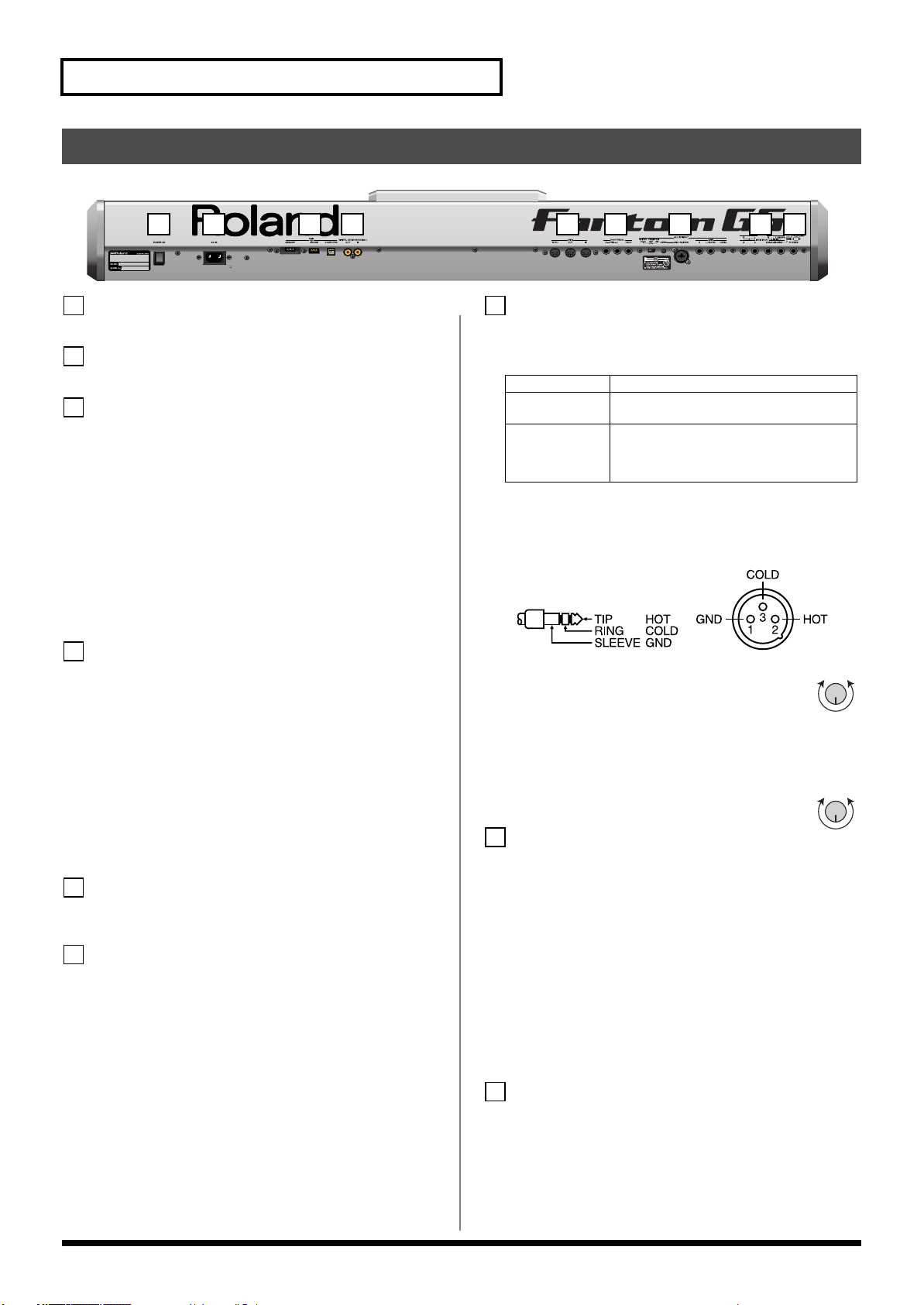
Panel Descriptions
4
Rear Panel
1 2 3 4 5 6 7 8 9
1
POWER ON Switch
Press to turn the power on/off. → (p. 28)
2
AC Inlet
Connect the included power cord to this inlet.
3
USB
USB MEMORY Slot
A USB memory (sold separately) can be inserted here.
* Never insert or remove a USB memory while this unit’s power is
on. Doing so may corrupt the unit’s data or the data on the USB
memory.
* Carefully insert the USB memory all the way in—until it is
firmly in place.
USB MOUSE Connector
Connect the USB mouse (sold separately). → (p. 26)
USB COMPUTER Connector
This connector lets you use a USB cable to connect your
computer to the Fantom-G. → (p. 285)
DIGITAL AUDIO IN/OUT Connectors
(S/P DIF COAXIAL)
These are coaxial-type S/P DIF format digital in/out connectors.
These connectors input and output a digital audio signal
(stereo). The output signal is identical to the signal that is output
from the OUTPUT A (MIX) jacks.
* S/P DIF is a digital interface format used for consumer digital
audio devices.
* If you switch off the power to an external device that is
connected to the DIGITAL AUDIO IN jack or disconnect the
cable, noise may subsequently be heard in the input from
DIGITAL AUDIO IN. If this occurs, correctly reconnect the
external device, or turn off the Fantom-G’s [MIX IN] switch.
5
MIDI Connectors (IN, OUT, THRU)
These connectors can be connected to other MIDI devices to
receive and transmit MIDI messages.
6
FOOT PEDAL
CTRL (CONTROL) 1, 2 Jacks
You can connect optional expression pedals (EV-5, etc.) or
optional pedal switches (DP series etc.) to these jacks. By
assigning a desired function to a pedal, you can use it to select or
modify sound or perform various other control. → (p. 31)
925
* Use only the specified expression pedal (EV-5; sold separately).
By connecting any other expression pedals, you risk causing
malfunction and/or damage to the unit.
HOLD Jack
An optional pedal switch (DP series, FS-5U etc.) can be
connected to this jack for use as a hold pedal. → (p. 31)
This can also be set so it supports the use of half-pedaling
techniques. So, after connecting an optional pedal switch (DP
series etc.), you can employ pedal work to achieve even finer
control in performances in which piano tones are used.
7
AUDIO INPUT
MIC/GUITAR Jack
You can connect either a mic or guitar. Set the Switch as appropriate
for the device you’ve connected to the MIC/GUITAR jack.
GUITAR (Hi-Z)
PHANTOM OFF
PHANTOM ON
* This instrument is equipped with balanced (XLR/TRS) type
jacks. Wiring diagrams for these jacks are shown below. Make
connections after first checking the wiring diagrams of other
equipment you intend to connect.
fig.XLR/TRSJack.eps
Guitar (High impedance supported)
Dynamic Mic: 1/4“phone plug (balanced or
unbalanced), XLR connector
Condenser Mic: XLR connector (48 V phan-
tom power supported)
* If you don’t need phantom power supply,
select the PHANTOM OFF position.
MIC/GUITAR LEVEL knob
Controls the volume of the mic/guitar input.
LINE Jacks (L, R)
Connect a line-level device such as an audio device (e.g.,
portable music player) or keyboard. If you want to use mono
input, connect to the L jack (p. 258).
LINE LEVEL knob
Controls the volume of the line input.
8
OUTPUT
OUTPUT A (MIX) Jacks (L (MONO), R)
These jacks output the audio signal to the connected mixer/
amplifier system in stereo. For mono output, use the L jack.
→
(p. 26)
OUTPUT B Jacks (L, R)
These jacks output the audio signal to the connected mixer/
amplifier system in stereo.
INDIVIDUAL 1–4 Jacks
These jacks output audio signals in mono to an amp or mixer.
* The setting determining whether these jacks are used as stereo
OUTPUT jacks or monaural INDIVIDUAL jacks is made with
the Output Assign setting. → (p. 152)
9
PHONES Jack
This is the jack for connecting headphones (sold separately).
→
(p. 26)
MinMax
MinMax
24
Page 25
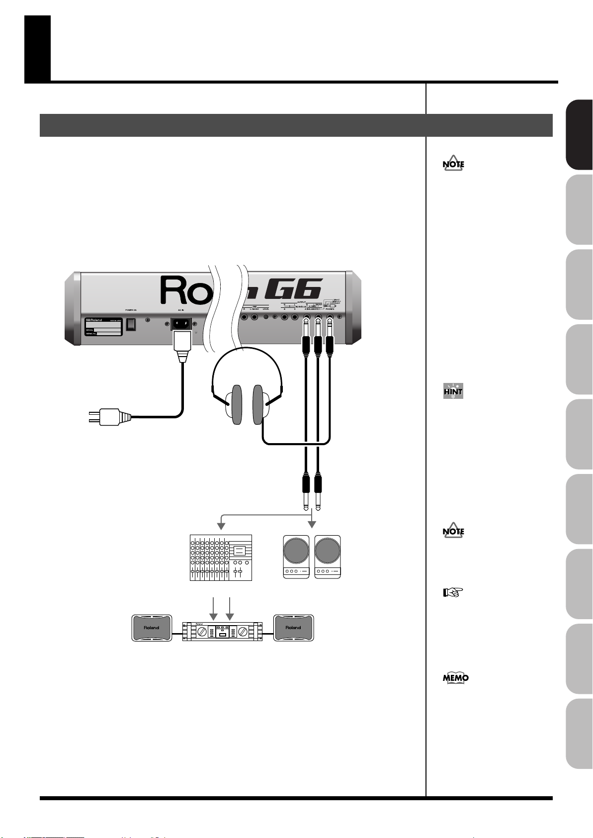
Making Connections
921
to Power outlet
Stereo headphones
Monitor speakers
(powered)
Power amp
Mixer etc.
In order to fully experience the
Fantom-G’s sound, we
recommend using a stereo
amp/speaker system. If you’re
using a mono system,
however, make your
connections to the Fantom-G’s
OUTPUT A (MIX) jack L
(MONO).
Connecting an Amp and Speaker System
Since the Fantom-G contains no amplifier or speakers, you’ll need to connect it to audio
equipment such as a keyboard amplifier, monitor speaker system or home stereo, or use
headphones to hear its sound.
1.
Before hooking anything up, make sure that the power on all of your gear is turned
OFF.
2.
Connect one end of the supplied power cable to the Fantom-G, and the other end to a
power outlet.
3.
Connect the Fantom-G to your amp/speaker system as shown in the diagram.
fig.02-002.e
Overview Sound 1 Sound 2 Sound 3 Pad Sampler
To prevent malfunction and/
or damage to speakers or other
devices, always turn down the
volume, and turn off the
power on all devices before
making any connections.
Audio cables are not included
with the Fantom-G. You’ll
need to provide them.
For details on how to install a
Expansion Board (sold
separately), refer to “Installing
the Expansion Board”
(p. 308, p. 310).
The OUTPUT A [MIX] jacks
support balanced output. Use
a correctly wired cable so that
the HOT, COLD, and GND as
printed on the rear panel of the
Fantom-G are correct for the
mixer or other input device
you’re using.
25
Menu/System
AppendixSequencer
Page 26
Making Connections
Connecting a USB Mouse (sold separately)
If you connect a commercially available USB mouse to the Fantom-G’s rear panel USB MOUSE
connector, a mouse cursor will be shown in the display, and you’ll be able to use the mouse.
Action
Left-click
Right-click [ENTER] button / list display
Wheel VALUE dial / scroll
Drag (move while hold-
ing down left button)
Click the button
Click the button
Click the button
Operation
Select (move the cursor)
Drag the mouse on the area or knob for which you
want to input a value. Dragging upward or to the
right will increase the value, and dragging downward
or to the left will decrease it.
Opens the menu (p. 280)
[EXIT] button
Opens the shortcut menu (p. 44)
26
Page 27
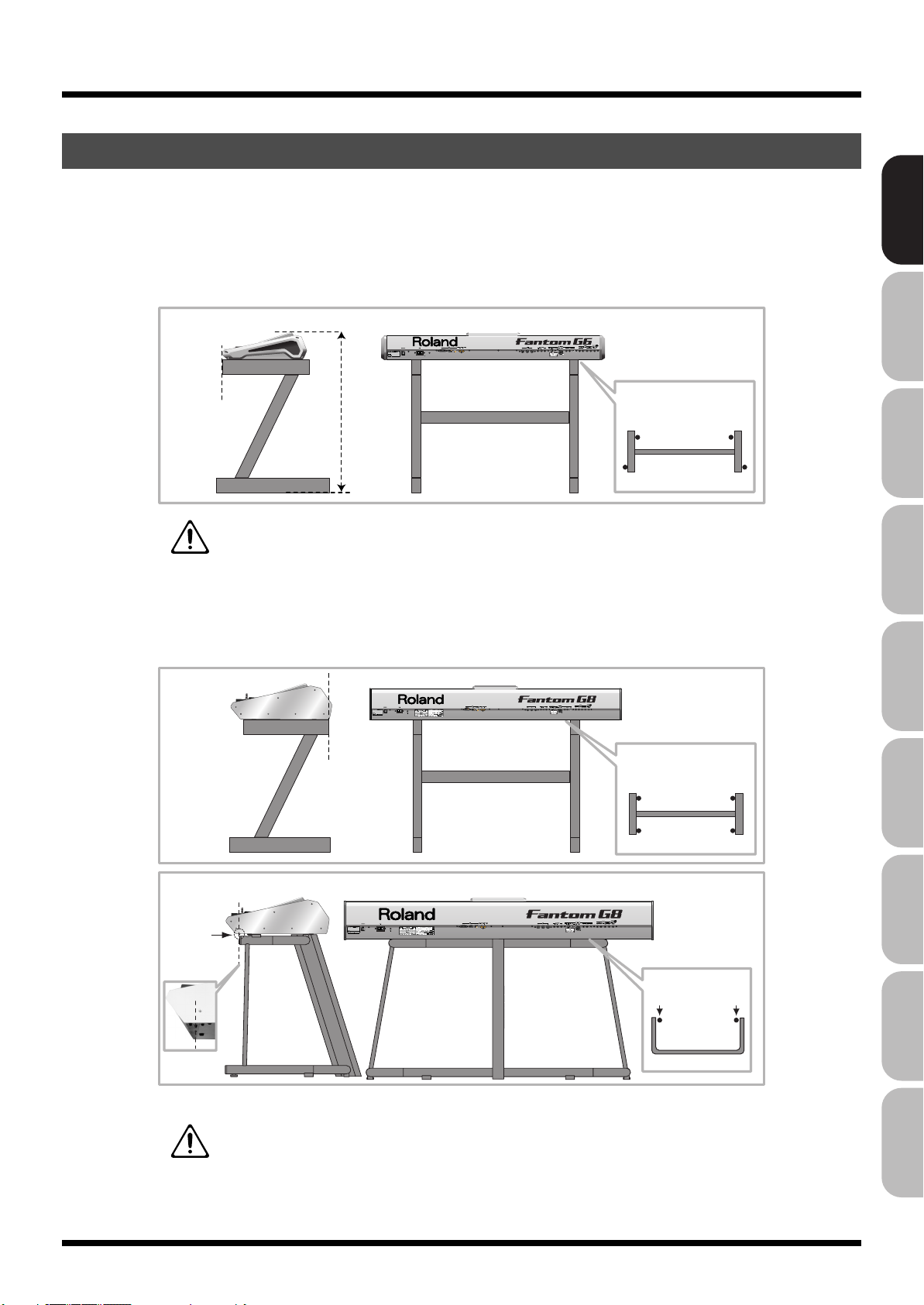
Making Connections
Placing the Fantom-G on a Stand
* Be careful not to pinch your fingers when setting up the stand.
For Fantom-G6/G7 user
If you want to place the Fantom-G6/G7 on a stand, use the Roland KS-18Z.
Place the instrument on the stand as follows.
fig.02-001.e
KS-18Z
Align the front of the
Fantom-G6/G7
with the front of
the stand
WARNING:
Use of stand not according to the instructions above will result in instability causing
possible injury.
For Fantom-G8 user
If you want to place the Fantom-G8 on a stand, use the Roland KS-18Z or KS-G8.
Place the instrument on the stand as follows.
fig.02-001.e
Adjust so that the
height does not
exceed 1 meter
(Adjust the stand
to a level no
higher than the
fourth level from
the bottom)
Adjust the width of the stand so that
the rubber feet of the Fantom-G6/G7
straddle the stand
Top view
Overview Sound 1 Sound 2 Sound 3 Pad Sampler
KS-18Z
KS-G8
Align the screws
of the Fantom-G8
with the front of
the stand
Adjust the width of the stand so that
Align the back of
the Fantom-G8 with
the back of the stand
the rubber feet of the Fantom-G8
are on the inside of the stand
Top view
Place the Fantom-G8 so
that it’s rubber feet are in the
inner side of the stand
Top view
WARNING:
Use of stand not according to the instructions above will result in instability causing
possible injury.
Menu/System
AppendixSequencer
27
Page 28
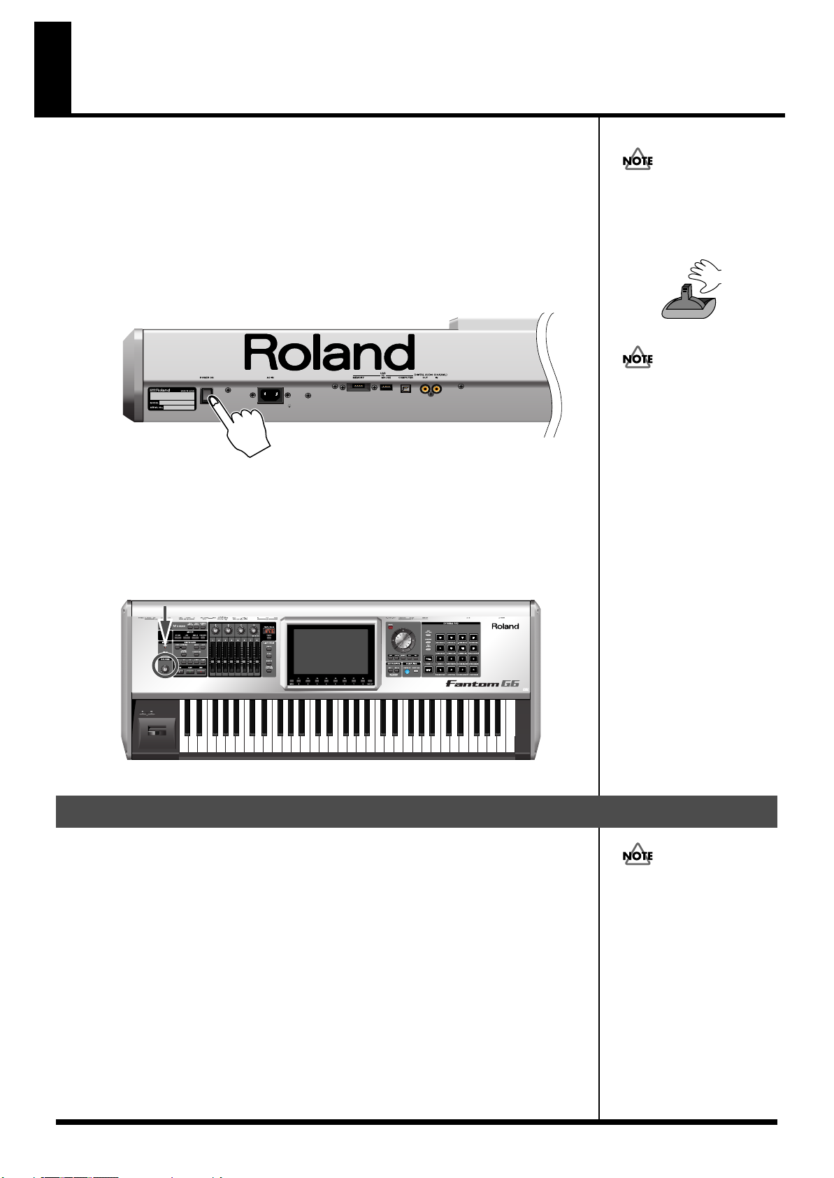
Turning On the Power
Once the connections have been completed (p. 25), turn on power to your various devices in
the order specified. By turning on devices in the wrong order, you risk causing malfunction
and/or damage to speakers and other devices.
fig.bender.e
1.
Before turning on the Fantom’s power, consider these two questions:
• Are all peripheral devices connected correctly?
• Have the volume controls of the Fantom-G and all connected audio devices been
turned to their lowest settings?
2.
Turn on the POWER ON switch located on the rear panel of the Fantom-G.
fig.02-003
* This unit is equipped with a protection circuit. A brief interval (a few seconds) after power
up is required before the unit will operate normally.
3.
Turn on the power for any connected amplifiers or speakers.
4.
Play the Fantom-G’s keyboard, gradually increasing the setting of its volume control,
and then carefully raise the volume of your connected amplifiers or speakers to the
desired listening level.
fig.02-004
941
To ensure proper operation of
the pitch bend lever, make
sure not to touch the lever
when turning the Fantom-G’s
power on.
Do not touch!
Be careful not to set your
listening volume too high to
avoid damage to your amp/
speaker system or your
hearing.
942
Turning Off the Power
1.
Before you turn off the power, consider these two questions:
• Have the volume controls for the Fantom-G and all connected audio devices been
turned to their lowest settings?
• Have you saved your Fantom-G sounds or other data you’ve created?
2.
Turn off the power for all connected audio devices.
3.
Turn off the POWER ON switch of the Fantom-G.
28
If you need to turn off the
power completely, first turn
off the POWER switch, then
unplug the power cord from
the power outlet. Refer to
“Power Supply” (p. 7).
Page 29
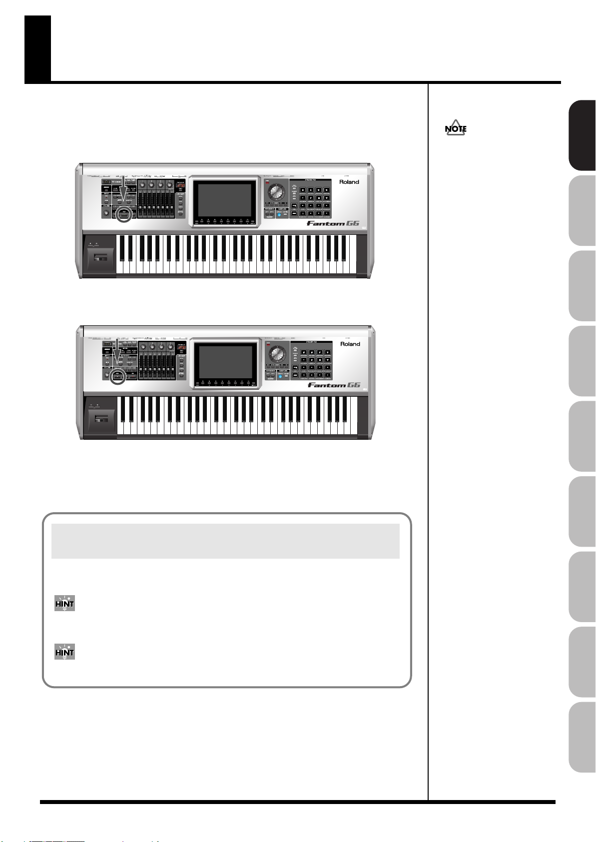
Listening to the Demo Songs
981
The Fantom-G has a demo song that will be loaded at start-up.
Here’s how to play the demo.
1.
Press [PLAY].
The demo song will play.
2.
Press [STOP] to stop demo song playback.
.
Overview Sound 1 Sound 2 Sound 3 Pad Sampler
a
All rights reserved.
Unauthorized use of this
material for purposes other
than private, personal
enjoyment is a violation of
applicable laws.
Song Automatically Loaded at Power-on (When Loading a Project)
When the Fantom-G is powered-on (when loading a project), song 001 (the top song in the
Song List) will be loaded automatically.
If you don’t want a song to be loaded automatically at power-on (when loading a project),
delete song 001 as described in “Deleting a Song File (Song Delete)” (p. 210).
When you execute a Factory Reset (p. 284), the demo song will be written to song 001.
Menu/System
AppendixSequencer
29
Page 30
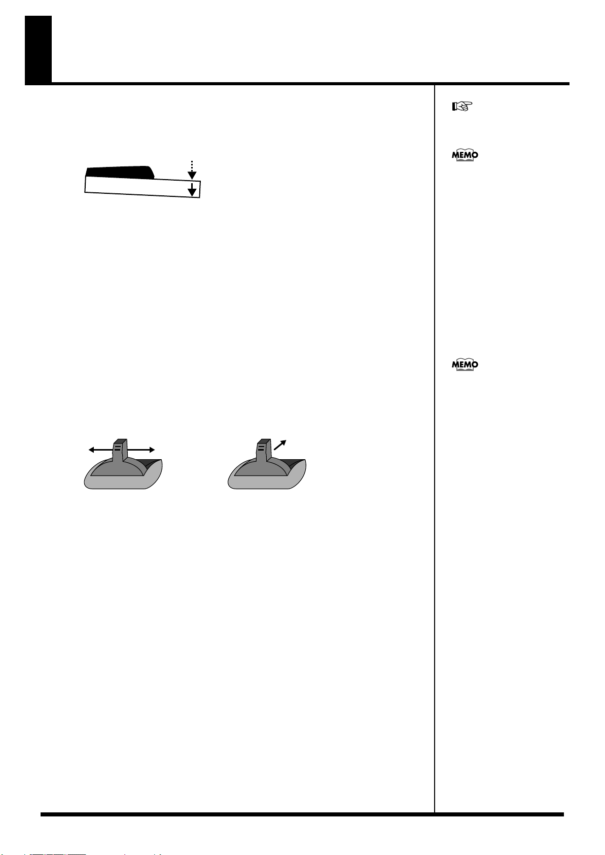
Various Performance Features
Velocity/Aftertouch
The force with which you play the keyboard, or the “velocity” with which you play, can affect
the volume or timbre of a sound. Aftertouch—downward pressure you apply to a key after
playing a note—can also affect the sound.
fig.02-008
For details on the setting, refer
to p. 292.
There are two types of
aftertouch: Polyphonic
Aftertouch, which applies
aftertouch to individual notes,
and Channel Aftertouch,
which applies aftertouch to an
entire MIDI channel (p. 251).
The Fantom-G can output the
MIDI data for Polyphonic
Aftertouch using the pads, and
Channel Aftertouch using the
keyboard.
Pitch Bend/Modulation Lever
While playing the keyboard, move the lever to the left to lower the pitch of the currently
selected patch, or to the right to raise its pitch. This is known as
vibrato by gently pushing the lever away from you. This is known as
If you push the lever away from you and at the same time move it to the right or left, you can
apply both effects at once.
fig.02-009.e
ModulationPitch Bend
Octave Shift (OCT)
You can shift the pitch of the keyboard in one-octave units over a range of +/-3 octaves.
Use KEYBOARD [-OCT] or [+OCT] at the left of the screen to make the desired setting.
To return to the original setting, press both buttons simultaneously.
Transpose
You can transpose the pitch of the keyboard in semitone units (-5– +6).
At the left of the display, turn on the KEYBOARD [TRANSPOSE] button, and then use the
[-OCT] or [+OCT] button to specify the desired transposition.
To return to the original setting, press both buttons simultaneously.
pitch bend
modulation
. You can also apply
.
You can set the amount of
pitch change for each patch (p.
96).
30
Page 31

Hold Pedal
Roland
The way in which the sound
changes will depend on the
settings. For details on settings
for parameters controlled by
the pedal, refer to “Making
Control Pedal Settings” (p.
77).
If an optional pedal switch (DP series) is connected to the rear panel PEDAL HOLD jack, you
can press the pedal switch to cause notes to sustain or “hold” even after their keys have been
released.
fig.02-010
Control Pedal
If an optional expression pedal or pedal switch (EV-5, DP series.) is connected to the rear panel
PEDAL CONTROL jack (1, 2), you can use the pedal to control the volume or various functions.
fig.02-011
Various Performance Features
For details on the setting, refer
to p. 291.
Overview Sound 1 Sound 2 Sound 3 Pad Sampler
Use only the specified
expression pedal or pedal
switch (EV-5, DP series, BOSS
FS-5U; sold separately). By
connecting any other
expression pedals, you risk
causing malfunction and/or
damage to the unit.
Menu/System
AppendixSequencer
31
Page 32

Overview of the Fantom-G
WG
Pitch
Envelope
TVF
TVF
Envelope
TVA
Envelope
TVA
LFO 1 LFO 2
Control signal
Tone
Audio signal
How the Fantom-G is Organized
Basic Structure
Broadly speaking, the Fantom-G consists of a
sound generator section, sequencer section
section
.
fig.04-001.j
Audio input
Sequencer section
128 MIDI tracks
24 audio tracks
Recording
(controllers such as the keyboard, pads, and pitch bend lever)
Playback
Controller section
Sampler section
Sound generator
Controller section
controller section
, and
SamplingRecording
section
Performance
,
sampler
Different Units of Sound
When using the Fantom-G, you’ll encounter various units of sound.
Here we’ll provide a simple explanation of these units.
Tone
A Tone is the smallest unit of sound in the Fantom-G. However, you
can’t play a tone by itself. The smallest unit of sound that you can
play is the “Patch,” so you can think of tones as the sonic material
that makes up each patch.
fig.04-002.j
This section includes the keyboard, pads, pitch bend / modulation
lever, the panel knobs, sliders, and D Beam controller, and pedals
connected to the rear panel.
Sound generator section
This section generates sound in response to performance data from
the controller section or sequencer section.
Sequencer section
This is a sequencer with 128 MIDI tracks and 24 audio tracks. The
MIDI tracks record performance data (MIDI) from the keyboard,
pads, and other controllers. The audio tracks record sound (audio)
from a mic or guitar connected to the Fantom-G’s audio input jacks.
Sampler section
A sampler is a device that captures (samples) sound from a CD
player or mic connected to the audio input or digital input, and
saves this sample as a wave file.
A captured sample can be used in the same way as the waveforms of
the sound generator section. You can also sample the sound of the
internal sound generator section itself (p. 258).
The Fantom-G can load WAV/AIFF format wave files from your
computer via USB as samples.
A tone consists of the following five elements.
WG (Wave Generator)
This selects the PCM waveform (wave) that is the basis of the sound,
and specifies how its pitch will change.
All of the patches built into the Fantom-G consist of combinations of
tones that are based on PCM waveforms (waves).
A rhythm tone (percussion instrument sound) contains four wave generators.
TVF (Time Variant Filter)
This specifies how the frequency components of the sound will
change over time.
TVA (Time Variant Amplifier)
This specifies volume change and panning.
Envelope
An envelope specifies a change over time. Dedicated envelopes are
provided for Pitch, TVF (filter), and TVA (volume). For example, if
you want to modify the time over which the sound starts or decays,
you would use the TVA Envelope settings to specify the desired
time-variant volume change.
LFO (Low Frequency Oscillator)
An LFO creates cyclic change (modulation). There are two LFOs, and
each can be applied to one aspect of the sound; WG (pitch), TVF
(filter), or TVA (volume). Applying an LFO to the WG pitch will
produce vibrato, applying it to the TVF cutoff frequency will produce
wah, and applying it to the TVA volume will produce tremolo.
32
A rhythm tone (percussion instrument sound) does not have an LFO.
Page 33

Overview of the Fantom-G
Live set
Part 1
Patch / Rhythm set / Sample set
Part 2
Patch / Rhythm set / Sample set
Part 3
Patch / Rhythm set / Sample set
Part 4
Patch / Rhythm set / Sample set
Part 5
Patch / Rhythm set / Sample set
Part 6
Patch / Rhythm set / Sample set
Part 7
Patch / Rhythm set / Sample set
Part 8
Patch / Rhythm set / Sample set
Patch
Patches are the basic unit of sound on the Fantom-G; they
correspond to an individual instrument such as “piano,” “organ,” or
“guitar.” A patch can consist of up to four tones. The Structure 1&2
and 3&4 parameters (p. 92) determine how the four tones are
combined. You can apply a “PFX (Patch MFX)” effect to each patch.
fig.04-003.j
Patch
Tone 4
Tone 3
Tone 2
Tone 1
WG
Pitch
Envelope
LFO 1 LFO 2
TVF
TVF
Envelope
TVA
TVA
Envelope
PFX
(PATCH MFX)
Rhythm set
A rhythm set is a group of percussion instrument sounds. Since
percussion instrument sounds are not usually used to play melodies,
there’s no need for them to produce different pitches when played
from the keyboard. Rather, it’s important that you have
simultaneous access to as many percussion instrument sounds as
possible. This is why in a rhythm set, each note (note number) of the
keyboard will play a different percussion instrument sound. You can
apply a “PFX (Patch MFX)” effect to each rhythm set.
fig.04-004.j
Rhythm set
Single / Live / Studio Modes
The Fantom-G can operate in the following three modes.
Single mode
Single mode is when you play a single patch (or rhythm set or
sample set), using the Fantom-G as a single piano, organ, etc. Choose
this mode when you want to edit a patch to create your own original
sound.
Live mode
Live mode is designed for live performance. It lets you play up to
eight patches (or either rhythm sets or sample sets) simultaneously.
For example, you can create layers (p. 62) in which a piano sound
and strings sound are heard simultaneously, or splits (p. 62) in
which your right hand plays a piano sound while your left hand
plays a bass sound.
Live set
Settings for Live mode can be saved as a “live set.”
Overview Sound 1 Sound 2 Sound 3 Pad Sampler
Note number 98 (D7)
Note number 97 (C#7)
Note number 36 (C2)
Note number 35 (B1)
Rhythm tone (percussion instrument sound)
WG (1-4)
Pitch
Envelope
TVF
TVF
Envelope
Envelope
TVA
TVA
PFX
(PATCH MFX)
Sample set
On the Fantom-G, a piece of wave data obtained by audio recording
or sampling is called a Sample. A sample set is a collection of sixteen
samples handled as a set. You can specify how each sample will play
when you press a pad or key.
Studio mode
Studio mode is designed to let you record a song. It provides sixteen
parts, and you can assign a patch (or rhythm set or sample set) to
each part, letting you use sixteen different sounds at the same time.
You can use the mixer screen to adjust the level and pan for each of
the sixteen parts.
Menu/System
Studio set
Settings for Studio mode can be saved as a “studio set.”
AppendixSequencer
33
Page 34

Overview of the Fantom-G
fig.04-005.j
Studio set
Part 16
About Polyphony
The Fantom-G has a maximum polyphony of 128 simultaneous
notes. Here we’ll explain how the polyphony is counted, and what
happens when the limit of 128 notes is exceeded.
Part 1
Patch /
Rhythm set /
Sample set
Part
On the Fantom-G, a “Part” is a kind of location or slot to which you
can assign a patch, rhythm set, or sample set.
Live mode gives you eight parts, and you can assign a patch, rhythm
set, or sample set to each part. This means that you can play up to
eight sounds together.
Studio mode gives you sixteen parts, and you can assign a patch,
rhythm set, or sample set to each part.
Part group
In addition to the internal parts (the internal sound generator), the
Fantom-G provides part groups for expansion boards 1 and 2, and
for the external MIDI output.
Part group
Internal
EXP 1 Expansion board 1 Up to 16
EXP 2
External
Explanation Number of parts
Internal
(internal sound generator)
Expansion board 2 Up to 16
External MIDI output 16
Live mode: 8
Studio mode: 16
* Depends on the expansion
board
* Depends on the expansion
board
How polyphony is counted
The Fantom-G can produce up to 128 notes simultaneously. This
number of notes will vary depending not only on the number of
notes you’re actually playing, but also on the number of tones used
by each patch, and the number of waves used by each tone. When
playing a patch, the polyphony is calculated as follows.
(number of patches that are sounding) x (number of tones used in the
currently sounding patches) x (number of waves used by those tones)
For example, if a patch consists of four tones, and each of these tones
uses two waves, it will use a total of eight notes of polyphony. If
you’re playing in Live mode (multi) or in Studio mode, count the
polyphony for each part to obtain the total polyphony of all parts.
* If you’re using realtime time stretch, twice as much polyphony will be
used.
Patch polyphony
If you attempt to play more than 128 notes simultaneously on the
Fantom-G, existing notes will be turned off, starting with the note
having the lowest priority of the currently sounding notes. This
priority is specified by the
You can choose either “LAST” or “LOUDEST” as the patch priority.
If you choose “LAST,” notes will be turned off starting with the firstplayed of the currently sounding notes when you exceed the 128
note limit. If you choose “LOUDEST,” notes will be turned off
starting with the note whose volume is least. Normally, you will
probably want to select “LAST.”
If you’re using multiple patches to play an ensemble, it’s important
to specify which part gets priority for its notes over the others. This
is specified by the
setting (p. 90) will determine how the notes of a patch are turned off.
Voice Reserve
Patch Priority
setting (p. 141). The
setting (p. 90).
patch priority
34
Voice reserve
The Fantom-G provides a
reserve a minimum number of notes for each part. For example, if
you specify a voice reserve setting of “10” for part 16, ten notes of
polyphony will be guaranteed to be available for the sound being
played by part 16 even when the overall Fantom-G reaches its 128
note limit. When making voice reserve settings, you’ll need to
consider the number of notes you actually want to play and the
number of tones in the patches you’re using (p. 141).
You can make voice reserve settings for up to a total of 64 notes
for all parts.
When the audio tracks of a song are playing back, the audio
tracks take priority over the voice reserve settings.
Voice Reserve
setting, which lets you
Page 35

Overview of the Fantom-G
EXP 2
Fantom-G
Factory data
Internal memory (50 MB)
Factory reset
USB storage
Temporary area
Project
Project
USB memory
(sold separately)
Expansion boards
(sold separately)
Project
Computer
SoundsSamples
System
Sequencer
Patches
USER: 512
EXP 1
Live sets
USER: 512
Studio sets
USER: 128
Rhythm sets
USER: 64
Sample sets
128
2000
samples
2000
phrases
50
songs
64
RPS sets
64
rhythm
pattern sets
Preset data
cannot be
overwritten
Patches
PRESET: 1668
GM: 256
Live sets
PRESET: 512
Studio sets
PRESET: 8
Rhythm sets
PRESET: 64
GM: 9
Waves
2230
(overwritable)
Load Save
LoadSave
Select
Expandable to
1 GB with
DIMM memory
(sold separately)
( )
About Memory
Temporary area
When you switch on the Fantom-G’s power or load a project, the
project data is placed in an area of memory called the “temporary
area.”
When you edit a patch or song, you are modifying the data in this
temporary area.
These edits will be lost if you simply turn off the power; if you want
to keep the changes you made, you must save them (SAVE/WRITE).
DIMM memory (sold separately)
You can install up to 1 GB of DIMM memory. Installing DIMM
memory will allow you to record or sample for a longer period of
time. For details on installing DIMM, refer to
Memory”
(p. 312, p. 314).
“Expanding the DIMM
USB memory (sold separately)
Internal memory can hold only one project, but commercially
available USB memory can hold multiple projects. Connect your
USB memory to the rear panel USB MEMORY connector (p. 24). For
details on how to format USB memory, refer to p. 284.
* If the USB memory is formatted using something other than FAT, it
will not be recognized by the Fantom-G. Use your computer to format
the USB memory with the “FAT” or “FAT32” file system. (If you’re
using Mac OS X, format the USB memory using the “MS-DOS file
system (FAT32).”)
Overview Sound 1 Sound 2 Sound 3 Pad Sampler
Project
The largest unit of memory handled by the Fantom-G is the
“project.” As shown in the illustration, a project contains sequencer
data, samples, sounds, and various system settings. On the FantomG you can use one project at a time.
Preset data
This is read-only data for patches, live sets, studio sets, rhythm sets,
and waves.
Internal memory
The Fantom-G has internal memory in which you can save a project.
A project can be overwritten at will. You can also restore the
memory to the factory-set condition (Factory Reset) (p. 284).
The internal memory is approximately 50 MB in size. If you need to
save a project that is larger than 50 MB, you’ll need to save it on USB
memory.
USB storage
You can use a USB cable to connect the Fantom-G to your hard disk,
and save (back up) projects from internal memory or USB memory
to the hard disk of your computer (p. 285).
Samples created using the Fantom-G can also be used by software on
your computer; or conversely, you can use your computer software
to create wave data and use it as samples in the Fantom-G.
Factory data
The factory data is memory that holds the factory-set state of the
internal memory. If you have deleted the factory-set patches or other
data from internal memory, and would like to use this data again,
you can execute the Factory Reset operation (p. 284).
* If you’ve created important data and saved it in the Fantom-G’s
internal memory, be aware that your data will be lost if you execute a
Factory Reset. (
also be lost
The data you’re in the process of editing will
.)
Expansion boards
(ARX series; sold separately)
Up to two expansion boards (ARX series; sold separately) can be
installed in the Fantom-G. An expansion board includes a sound
generator engine, and will expand both the number of available
sounds and the polyphony. For details on installing expansion
boards, refer to
“Installing the Expansion Board”
(p. 308, p. 310).
Menu/System
AppendixSequencer
35
Page 36

Overview of the Fantom-G
MIDI track 128
MIDI track 2
MIDI track 1
Audio track 24
Audio track 2
Audio track 1
Tempo track
Beat track
Phrase
1
Phrase
2000
Song
Phrases
Sample
1
Sample
2000
Samples
About the Internal Effects
Types of Effects
The Fantom-G contains the following effects units. You can make
settings independently for each one.
PFX (Patch MFX) (Patch multi-effect)
This is a dedicated multi-effect unit for the patch. You can use it as
part of the sound of the patch itself.
You can choose from 76 types including distortion and rotary.
MFX (Multi-effect)
This is a general-purpose multi-effect that can apply various
modifications to the sound.
You can choose from 78 types including distortion and rotary.
Chorus
Chorus is an effect that adds depth and spaciousness to the sound.
You can choose whether to use this as chorus or as delay.
About the Sequencer
Audio and MIDI
The Fantom-G’s sequencer can record audio and MIDI.
Audio (samples)
Audio is a “recording” of the sound from a mic or portable audio
player connected to the Fantom-G’s input jacks. The recorded audio
data is called a “sample.” You can create a song simply by placing
samples in an audio track.
MIDI (phrases)
MIDI records performance data from the keyboard or pads. The
recorded MIDI data is called a “phrase.” You can create a song
simply by placing phrases in a MIDI track.
In the sense that both types of recording can be used to capture a
performance, MIDI is similar to audio, but while audio recording
captures the “sound” of a performance, MIDI recording captures the
notes and other control data of a performance, and allows you to
freely make detailed edits even to the individual note data.
Reverb
Reverb is an effect that simulates the reverberation that characterizes
sounds heard in a hall or other acoustic environment. You can
choose from 10 types of reverb.
Mastering effect
This is a stereo compressor (limiter) applied to the final output of the
Fantom-G. It operates independently for high, mid, and low
frequency bands, compressing sounds that exceed the specified
volume level, and making the overall sound more consistent.
Input effect
This is a dedicated effect for the external input.
You can choose from six types, including equalizer and compressor.
What is a Song?
Performance data for one composition is called a “
consists of audio tracks 1–24, MIDI tracks 1–128, a tempo track, and a
beat track.
fig.04-009.j
song
.” This
36
Page 37

Overview of the Fantom-G
What is a Track?
A track is an area in which performance data can be recorded.
Audio tracks 1–24
There are twenty-four tracks for recording audio.
Samples
A piece of recorded audio data is called a “sample.” You can create
up to 2,000 samples in one project. The Fantom-G can capture
samples by sampling (p. 258), or by importing WAV/AIFF format
wave files via USB from your computer (p. 287). You can also create
a song by placing samples in an audio track.
Samples also support the Sample Pad function (p. 191) which lets
you play samples simply by pressing a pad.
MIDI tracks 1–128
There are 128 MIDI tracks that can record MIDI performances. A
MIDI track can be assigned to the Fantom-G’s 16 parts (Studio
mode), to the two sets of up to 16 parts for the expansion boards (the
number of parts will depend on the expansion board), or to the 16
parts of the external MIDI connector. You can also assign multiple
tracks to a single part (for example, tracks 1 and 2 could be assigned
to the Fantom-G’s part 1.)
Phrases
The MIDI data recorded in a MIDI track is called a “phrase.” Up to
2,000 phrases can be created in a single project. Just like a track, each
phrase can record a performance of 16 MIDI channels. You can also
create a song simply by placing phrases in a MIDI track.
Phrases also support the RPS function that lets you instantly play a
phrase simply by pressing a pad (p. 194), and the Rhythm Pattern
function that lets you play rhythm patterns by pressing a pad (p.
196). This means that you can use phrases to record performance
data for use in a live performance.
You can also use phrases to record your musical ideas.
Tempo track
The tempo track records tempo changes for the song. Use it when
you want the tempo to change during the song. If the tempo is going
to stay the same from the beginning to the end of the song, you can
ignore the tempo track.
When you record a song on the Fantom-G, the tempo you specify at
the time of recording is stored at the beginning of the tempo track.
This means that this tempo will always be used every time you play
back the song.
In this way, songs are played back according to the data in their
tempo track, but if you change the tempo during playback, the
overall tempo of the entire song will change accordingly.
Beat track
The beat track records time signature information for each measure
of the song. You’ll make beat track settings when recording a new
song, or when you want the time signature to change during the
song.
Songs and the State of the Sound Generator
The Fantom-G’s sequencer is available at all times, regardless of the
sound generator mode (Single, Live, or Studio).
In Studio mode, you can record separate performances for each part
using up to sixteen sounds. This makes Studio mode the ideal choice
when you want to record or play back a song using an ensemble of
multiple instruments such as drums, bass, and piano.
SMF (Standard MIDI File .MID)
SMF (Standard MIDI File) is a file format that allows performance
data to be exchanged between music applications. Songs created on
the Fantom-G can be saved as standard MIDI files (p. 256). The
Fantom-G can also play back commercially available music data that
is compatible with the GM/GM2 system (GM Scores).
Overview Sound 1 Sound 2 Sound 3 Pad Sampler
37
Menu/System
AppendixSequencer
Page 38

Overview of the Fantom-G
About the Sampling Section
The sampling section “samples” (records) audio input from an
external source such as an audio device or mic. You can play these
sampled sounds as a patch or rhythm set. You can also import
WAV/AIFF format files and use them in the same way.
Samples
A “sample” refers to a waveform (wave) produced by sampling on
the Fantom-G. A sample consists of waveform data together with
parameters such as a start point, loop start, and loop end. The
Fantom-G can hold up to 2,000 samples for a single project.
fig.04-011.j
Sample
Sample list
0001
User Sample
0002
added
2000
Drum sound
Sampling
Wave
(sample)
Automatically
38
Page 39

Basic Operation of the Fantom-G
Switching the Sound Generator Mode
The Fantom-G provides three sound generator modes: Single, Live,
and Studio. You can switch to the sound generator mode that’s most
appropriate for the way you’re using the Fantom-G.
Single mode
This mode is for playing one sound (patch, rhythm set, sample set) at
a time.
< To select Single mode >
1.
Press [SINGLE].
fig.04-014_50
Live mode
This mode is for combining multiple sounds (patches, rhythm sets,
sample sets) so that you can play them in a live performance.
You can layer patches so that they sound simultaneously, or split
them across the keyboard so that they can be played by separate
hands.
< To select Live mode >
1.
Press [LIVE].
fig.04-015_50
Overview Sound 1 Sound 2 Sound 3 Pad Sampler
“Playing in Single Mode”
(p. 46)
“Playing in Live Mode”
(p. 58)
Studio mode
This mode is for recording a song using multiple sounds (patches,
rhythm sets, sample sets).
This mode is ideal when you need to adjust mixing parameters such
as level and pan for the sixteen parts.
< To select Studio mode >
1.
Press [STUDIO].
fig.04-016_50
Menu/System
“Playing in Studio Mode”
AppendixSequencer
(p. 66)
39
Page 40

Basic Operation of the Fantom-G
Windows
A small screen displayed within the normal screen is called a
“
window.” Various types of windows will appear as you
operate the Fantom-G. Some windows display lists, others
allow you to make settings or confirm operations.
fig.04-018.j
To close a window, press [EXIT]. Some windows will close
automatically when you perform an operation.
Cursor
How the Function Buttons Work
The eight buttons [F1]–[F8] located below the display (the function
buttons) are used to execute various functions. Their function will
depend on the screen that’s currently shown. The current functions
of these buttons are indicated in the bottom of the screen.
fig.04-017
Moving the Cursor
A single screen or window can contain multiple items (parameters)
to set or select. If you want to modify the setting of a parameter,
move the cursor to the value of that parameter. To select an item,
move the cursor to the desired item. The value or item selected by
the cursor will be highlighted.
fig.04-019.j
Use
fig.04-020
/ / / (cursor buttons) to move the cursor.
: Moves the cursor upward.
: Moves the cursor downward.
: Moves the cursor to the left.
: Moves the cursor to the right.
If you hold down a cursor button and then press the opposite
cursor button, the cursor will move more rapidly in the
direction of the button you pressed first.
In some cases, pressing [ENTER] while the cursor is displayed
will show a list of the parameters you can select. This is a
convenient way to see the choices you have. When a list is
displayed, you can also use the pads to input your choice (p. 41).
Using the mouse for selection
If you’re using a USB mouse, you can move the cursor by clicking
the mouse on a parameter value.
40
Page 41

Basic Operation of the Fantom-G
Numerals
Editing a Value
To edit a value, you can use either the VALUE dial or [INC] [DEC].
In each of the Fantom-G’s screens, move the highlighted cursor
to the value you want to edit, and then edit the value.
VALUE dial
Turn the VALUE dial toward the right to increase the value, or
toward the left to decrease it. The value will change in larger steps if
you hold down [SHIFT] while turning the VALUE dial.
When the cursor is located at a parameter value, pressing
[ENTER] (or right-clicking the USB mouse) will open a window
where you can specify the value. You can easily select a value
by pressing or to select the desired value and then
pressing [ENTER].
Using the pad for numeric input
If you press the [NUMERIC] pad button, the pads will operate as
numeric keys.
Each pad will enter the following values
Pad
1–9
10 0
11 +
12 15 , (comma)
16 BS (backspace)
ROLL Cancel
HOLD Enter
When you’ve entered the value, press [ENTER] to finalize your
input. If you decide to cancel, press [EXIT].
Value entered
1–9
Overview Sound 1 Sound 2 Sound 3 Pad Sampler
[INC], [DEC]
Press [INC] to increase a value, or [DEC] to decrease it. To make the
value continue increasing (or decreasing), hold down the button. To
make the value increase rapidly, hold down [INC] and then press
[DEC]. Conversely, to make the value decrease rapidly, hold down
[DEC] and then press [INC].
The value will change in larger steps if you hold down [SHIFT]
while you press [INC] or [DEC].
Using the mouse for input
Drag up/down or left/right on the value or knob. Dragging up or to
the right will increase the value, and dragging down or to the left
will decrease the value.
Using the knobs for input
If the display shows small numerals (
can use knobs 1–4 to edit the corresponding parameters.
, , , ), you
Menu/System
AppendixSequencer
41
Page 42

Basic Operation of the Fantom-G
Assigning a Name
On the Fantom-G you can assign a name to each patch, rhythm set,
live set, studio set, song, phrase, or sample when you save it.
Regardless of the type of object you’re naming, the procedure is the
same.
1.
Use [CURSOR] to move the cursor to the position at which
you want to enter a character.
fig.04-022a
2.
Turn the VALUE dial or use [INC] [DEC] to specify the
character that you want to enter.
• [F5 (Delete)]: Deletes the character at the cursor, and moves
the subsequent characters one place forward.
• [F6 (Insert)]: Inserts a space at the cursor location.
• [F7 (Cancel)]: Cancels the name entry procedure.
• [F8 (OK)]: Confirms the name.
•[ ] [ ]: Move the cursor.
•[ ] [ ]: Switch between uppercase and lowercase letters.
Using a mouse to input characters
If you’re using a USB mouse, you can enter characters using a virtual
keyboard.
1.
Click the mouse on the keyboard icon
the name entry screen.
The virtual keyboard will appear.
2.
Click the mouse on the keyboard to enter characters.
3.
Press [F8 (OK)] or click it with the mouse to finalize the
input.
If you use the virtual keyboard for entry, it will be shown again
the next time you enter a name.
shown in
You can use the following characters,
space, A–Z, a–z, 0–9, ! ” # $ % & ’ ( ) * + , - . / : ; < = > ? @ [ \ ] ^ `
{ | }
When assigning a name to a song file, you can’t use spaces,
lowercase letters, or certain symbols (\ / : , ; * ? ” < > |).
42
Page 43

Basic Operation of the Fantom-G
Basic Pad Operations
For details on using the pads, refer to
Switching the Pad Mode
The pads have sixteen modes. Press [PAD MODE] to switch the pad
mode.
1.
Press [PAD MODE].
[PAD MODE] will blink, and
the currently selected pad
mode (pad [1]–[16]) will
blink.
If you decide not to switch the
pad mode, press [PAD
MODE] once again. [PAD
MODE] will go out and you
will return to the previous state.
2.
Press a pad [1]–[16].
The pad mode will be switched. The following table shows
what the pads do in each mode, and a page reference where you
can learn more.
“Using the Pads”
(p. 188).
Viewing the Pad Settings
Press [PAD SETTING], and the
setting/information screen for
the currently selected pad mode
will appear.
To go back to where you
were, press [PAD SETTING]
once again so its light goes
out.
Using the Pads as Numeric Keys
If you press PAD [NUMERIC],
the pads will operate as numeric
keys. →
“Using the pad for
numeric input”
(p. 41)
Overview Sound 1 Sound 2 Sound 3 Pad Sampler
Pad
number
Pad mode Explanation
SAMPLE PAD Play a sample set p. 191
1
2 RHYTHM Play a rhythm set p. 192
3 CHORD MEMORY Switch the chord form of the
4 ARPEGGIO Switch the style of the Arpeggio
5 RPS Play phrases p. 194
6 RHYTHM PTN Play rhythm patterns p. 196
7 TONE SEL/SW Act as tone select and on/off
8 TRACK MUTE Switch the mute status of the se-
9 BOOKMARK Call up frequently used screens
10 MIDI TX SW Act as on/off switches for exter-
11 EFFECT SW Act as effect switches (except for
12 PATCH MFX SW Act as multi-effect switches for
13 PART SELECT Select parts (1–16) and banks
14 PART MUTE Switch the mute status of parts
15 USER GROUP Store/load user group patches,
16 FAVORITE Store/load favorite settings p. 202
Chord Memory function (p. 81)
function (p. 78)
switches
quencer tracks
you’ve registered for each pad
nal MIDI transmit channels (1–
16)
patch multi-effect)
each part
(INT/EXP1/EXP2/EXT)
(1–16) and banks (INT/EXP1/
EXP2/EXT)
live sets, or studio sets
Page
reference
p. 193
p. 193
p. 197
p. 197
p. 198
p. 198
p. 199
p. 199
p. 200
p. 200
p. 201
Menu/System
AppendixSequencer
43
Page 44

Basic Operation of the Fantom-G
Shortcut Menu
By pressing the [
most important screens.
1.
Press [DISPLAY].
The Shortcut menu will appear.
You can also open the Shortcut menu by clicking your USB
mouse on the shortcut icon.
2.
Press
jump, then press [F8 (Select)].
If you decide to cancel, press [F7 (Cancel)].
DISPLAY
or to select the screen to which you want to
] button, you can jump directly to the
List of shortcut menu
Menu
Studio Play/Live Play/Single Play
Patch Zoom Edit p. 84
Patch Pro Edit p. 86
Song Play/Song Edit p. 205, p. 232
Sample Edit p. 266
Effects Routing p. 151
Sampling p. 260
Input Setting p. 258
Digital/USB Input Level p. 301
Master Level p. 297
Pad Setting p. 190
Page
p. 66, p. 58. p. 46
44
Page 45

02: Sound Generator, Section 1
This chapter explains the three modes in which the Fantom-G’s sound generator can
operate.
• Single Mode ..............................................................p. 46
• Live Mode.................................................................. p. 58
• Studio Mode .............................................................. p. 66
(Playing Sounds)
Page 46

Playing in Single Mode
6
7
9
10 11
8
5
1 2 3 4
5
In Single mode, the keyboard and the pads are each used to play a
single sound (patch/rhythm set/sample set).
About the Single Play Screen
Displaying Single Play Screen
To access the Single Play screen, use the following procedure.
1.
Press [SINGLE].
You will enter Single mode, and the Single Play screen appears.
F-key operations in the Single Play screen
F-key
F1
Patch List
F3
Part View
F4
Control
F5
PFX
F6
User Group
F7
Patch Edit
F8
Tone Sw/Sel
Explanation Page
Select a sound (patch). p. 49
Make detailed settings for each part (keyboard, sample pad, rhythm part).
Select the parameters that will be controlled
by the realtime controllers and D Beam controller.
Access the PFX (Patch Multi-effect) editing
screen.
Access the user group list screen, where you
can register frequently-used patches.
Edit a patch. p. 84
Select the tones that will be heard. p. 50
p. 51
p. 51
p. 157
p. 201
Functions in the Single Play screen
fig.05-005.e
Number
1
2
3
4
6
7
8
9
10
11
Explanation
Indicates the current sound generator mode.
Indicates the on/off status of each effect.
PFX Patch multi-effect
MFX1 Multi-effect 1
MFX2 Multi-effect 2
IFX Input effect
CHO Chorus
REV Reverb
MAS Mastering effect
Indicates the current location of the song, and the
status of the sequencer.
The Menu/Exit/Shortcut buttons for the USB
mouse.
Indicates/selects the part group, part number, patch
type, bank, number, and name of the selected patch,
rhythm set, or sample set.
Indicates/selects the patch category, and specifies
whether the category will be locked.
Indicates the pad mode. p. 188
Indicates/selects the part group, part, pad type,
bank, number, and name of the rhythm set or sample
set selected for the pads.
Indicates the functions assigned to the realtime controller sliders (1–8), knobs (1–4) and the S1/S2
switches.
Indicates the
lever.
Indicates the function assigned to the D Beam controller and the state of D Beam controller response.
“Bend Mode”
(p. 97) of the pitch bend
Page
p. 39
p. 150
p. 205
p. 26
p. 47
p. 48
p. 52
p. 51
p. 97
p. 72
46
Page 47

Selecting a Patch
The Fantom-G has four patch banks, including the User, Preset, User
Sample and GM.
USER
This is the bank inside the Fantom-G which can be rewritten. Patches
you create can be stored in this bank. You can store 512 patches.
PRST (Preset)
This is the bank inside the Fantom-G which cannot be rewritten.
However you may modify the settings of the currently selected
patch, and then store the modified patch in user bank.
Playing in Single Mode
1.
Press [SINGLE] to access the Single Play screen.
fig.05-001.e
Patch type Patch bank Patch category
Patch number / Patch name
Overview Sound 1 Sound 2 Sound 3 Pad Sampler
GM (GM2)
This is an internal bank of patches compatible with General MIDI 2,
a system of MIDI function specifications designed to transcend
differences between makers and types of devices; these patches
cannot be overwritten. However you may modify the settings of the
currently selected patch, and then store the modified patch in user
bank. The Fantom-G includes 256 preset patches.
USAM (User Sample)
This bank lets you play the Fantom-G’s internal samples.
2.
Press [CURSOR] to move the cursor to the patch bank.
Turn the VALUE dial or use [INC] [DEC] to choose the patch
bank.
USER:
PRST:
GM:
USAM:
* Make sure that the patch type is set to “Patch.”
If this is set to “Rhythm” or “Sample,” use [CURSOR] to move the
cursor to the patch type, and turn the VALUE dial or press [DEC] to
select “Patch.”
3.
Press [CURSOR] to move the cursor to the patch number.
4.
Turn the VALUE dial, or press [INC] [DEC] to select a patch
number.
You can also use the pads as numeric keys to enter numbers
(patch numbers). → “Using the pad for numeric input”
5.
Play the keyboard to hear the sound.
You can also use the following methods to select a patch.
“Selecting Patches by Category (Patch Finder)”
“Selecting Patches from the List”
User
Preset
GM (GM2)
User Sample
(p. 48)
(p. 49)
(p. 41)
47
Menu/System
AppendixSequencer
Page 48

Playing in Single Mode
Selecting Patches by Category (Patch Finder)
The Fantom-G provides a “Patch Search function” (Patch Finder)
which allows you to specify a type (category) of patch so that you
can quickly find the desired patch. There are a total of 38 categories.
1.
Press [SINGLE] to access the Single Play screen.
fig.05-001.e
Patch type Patch bank Patch category
Patch number / Patch name
* Make sure that the patch type is set to “Patch.”
If this is set to “Rhythm” or “Sample,” use [CURSOR] to move the
cursor to the patch type, and turn the VALUE dial or press [DEC] to
select “Patch.”
2.
Use [CURSOR] to move the cursor to the “Patch Category,”
and turn the VALUE dial, or press [INC] [DEC] to select the
desired category.
3.
Press
VALUE dial or press [INC] to turn “ON”.
4.
Use [CURSOR] to move the cursor to the patch bank or
patch number, and turn the VALUE dial or use [INC] [DEC]
to select the patch.
When the cursor is located at the Patch bank, you can select the
bank. When the cursor is located at the Patch number, you can
specify the number.
You are free to change the category of a patch by editing the
Patch Pro Edit screen (p. 86) parameter
89).
to move the cursor to “Categ Lock,” and turn the
“Patch Category”
(p.
The following categories can be selected.
Category
- - PNO AC.Piano Acoustic Piano
EP EL.Piano Electric Piano
KEY Keyboards Other Keyboards (Clav,
BEL Bell Bell, Bell Pad
MLT Mallet Mallet
ORG Organ Electric and Church Organ
ACD Accordion Accordion
HRM Harmonica Harmonica, Blues Harp
AGT AC.Guitar Acoustic Guitar
EGT EL.Guitar Electric Guitar
DGT DIST.Guitar Distortion Guitar
BS Bass Acoustic & Electric Bass
SBS Synth Bass Synth Bass
STR Strings Strings
ORC Orchestra Orchestra Ensemble
HIT Hit&Stab Orchestra Hit, Hit
WND Wind Winds (Oboe, Clarinet etc.)
FLT Flute Flute, Piccolo
BRS AC.Brass Acoustic Brass
SBR Synth Brass Synth Brass
SAX Sax Sax
HLD Hard Lead Hard Synth Lead
SLD Soft Lead Soft Synth Lead
TEK Techno Synth Techno Synth
PLS Pulsating Pulsating Synth
FX Synth FX Synth FX (Noise etc.)
SYN Other Synth Poly Synth
BPD Bright Pad Bright Pad Synth
SPD Soft Pad Soft Pad Synth
VOX Vox Vox, Choir
PLK Plucked Plucked (Harp etc.)
ETH Ethnic Other Ethnic
FRT Fretted Fretted Inst (Mandolin etc.)
PRC Percussion Percussion
SFX Sound FX Sound FX
BTS Beat&Groove Beat and Groove
DRM Drums Drum Set
CMB Combination Other patches which use
No Assign No assign
You can’t select categories for rhythm sets or sample sets.
Contents
Harpsichord etc.)
Split and Layer
48
Page 49

Playing in Single Mode
Selecting Patches from the List
You can display a list of patches and select a patch from that list.
1.
Press [SINGLE] to access the Single Play screen.
2.
Press [F1 (Patch List)].
The Patch List screen will appear.
fig.05-008_50
You can use [F3 (Patch)], [F4 (Rhythm Set)], and [F5 (Sample
Set)] to switch between patch types (patches, rhythm sets,
samples sets).
3.
Use [F1] [F2] or
You can also use the front panel [Knob 4] to select a category,
and use [Slider 8] to scroll the list.
→ “Magic Control”
/ to select a category.
(p. 294)
Auditioning Patches (Phrase Preview)
The Fantom-G allows you to preview patches by hearing a phrase
appropriate for each type of patch.
1.
Press [SINGLE] to access the Single Play screen.
2.
Press [F1 (Patch List)] to access the Patch List screen.
fig.05-009_50
3.
Press and hold [F7 (Preview)].
The patch selected in the Patch List screen will be sounded.
4.
Release your finger from [F7 (Preview)], and the phrase will
stop playing.
If you wish to change how the phrase is played by Phrase
Preview, you can edit the Preview Mode parameter (p. 300).
Overview Sound 1 Sound 2 Sound 3 Pad Sampler
You can’t select categories for rhythm sets or sample sets.
4.
Turn the VALUE dial or use [DEC] [INC] or
select a patch.
You can press [F7 (Preview)] to audition the patch using an
appropriate phrase that is preset for each category (Phrase
Preview).
By pressing [F6 (User Group)] you can register a frequently
used sound in the user group. For details, refer to
a sound in the User Group screen”
If you’re using a USB mouse, you can click the keyboard symbol
in the screen, and search using the virtual keyboard
that appears in the screen.
5.
Press [F8 (Select)] to confirm your patch selection.
(p. 201).
/ to
“Registering
Menu/System
AppendixSequencer
49
Page 50

Playing in Single Mode
Selecting the Tones That Will Sound (Tone On/Off)
Since a patch is a combination of up to four tones, you can switch
unwanted (tones out of the four) off and get just the sound of a
specific tone.
1.
Press [SINGLE] to access the Single Play screen.
2.
Press [F8 (Tone Sw/Sel)].
The Tone Switch/Select window appears.
fig.05-014_50
3.
Press [F1 (Tone Sw)]–[F4 (Tone Sw)] to turn each tone on/
off. The setting will switch on/off each time you press the
button.
4.
Press [EXIT] to close the window.
Playing Single Notes (Monophonic)
When using a patch for a naturally monophonic instrument such as
sax or flute, it is effective to play in mono.
1.
Press [SINGLE] to access the Single Play screen.
2.
Press [PATCH] twice to access the Patch Pro Edit screen.
If you want just one or two tones to sound in a patch, turn the
others off and store that setting on a patch. This cuts
nonessential use of the Fantom-G’s simultaneous voices.
You can also use the pads to select tones and switch them on/
off (p. 197).
3.
Press [F1 (Up)] or [F2 (Down)] to select the “Solo/Porta”
tab.
A screen like the one shown below appears.
fig.05-015_50
4.
Press or to move the cursor to “Mono/Poly.”
5.
Turn the VALUE dial or press [DEC] to select “MONO.”
Now you can play in mono mode.
If you assign “MONO/POLY” as a function to be controlled by
the assignable switch ([S1] [S2]), you can easily switch between
mono/poly by pressing a button (p. 77).
50
Page 51

Playing in Single Mode
Part Settings (Part View)
Single mode has the following three parts.
Part
1
Keyboard The part that is heard when you play the
7 Sample
Pad
8 Rhythm
Pad
In the Part View screen you can view and edit the volume and pan
settings of these three parts.
1.
Press [SINGLE] to access the Single Play screen.
2.
Press [F3 (Part View)].
The Part View screen will appear.
fig.08-017_50
Explanation
keyboard
The part that is heard when you set the
pads to
“1 SAMPLE PAD (Using the
Pads to Play Samples)”
The part that is heard when you set the
pads to
“2 RHYTHM (Using the Pads to
Play a Rhythm Set)”
(p. 191) mode
(p. 192) mode
Selecting the Parameter
Controlled by the Realtime
Controllers or D Beam
Controller (Control Setting)
The Fantom-G lets you assign the parameters that will be affected
when you operate the 1–4 knobs, 1–8 sliders, S1/S2 switches, D
Beam, pitch bend, or modulation lever. This lets you modify the
sound in a variety of ways by operating the controllers.
1.
Press [SINGLE] to access the Single Play screen.
2.
Press [F4 (Control)].
The Control Setting screen will appear.
3.
Press [F1 (Up)] or [F2 (Down)] to select the parameter
group.
4.
Use [CURSOR] to move the cursor to the parameter.
5.
Either turn the VALUE dial or use [INC] [DEC] to set the
value.
Overview Sound 1 Sound 2 Sound 3 Pad Sampler
3.
Press [F1 (Up)] or [F2 (Down)] to select the parameter
group.
4.
Use [CURSOR] to move the cursor to the parameter.
5.
Either turn the VALUE dial or use [INC] [DEC] to set the
value.
6.
If you want to keep the settings, press [F7 (Sys Write)].
When Single mode is selected, part settings cannot be saved for
each individual patch. Part settings are saved as system
settings.
7.
When you have finished making settings, press [EXIT] to
return to the Single Play screen.
See
“Level/Pan (When the Part Group is Internal/EXP1/
EXP2)”
(p. 134)–
functions.
“MIDI Rx Filter”
(p. 141) for each parameter’s
6.
If you want to keep the settings, press [F7 (Sys Write)].
When Single mode is selected, controller settings cannot be
saved for each individual patch. Controller settings are saved as
system settings.
7.
When you have finished making settings, press [EXIT] to
return to the Single Play screen.
See
“Keyboard Mode”
parameter’s functions.
(p. 143)–
“Ctrl Switch”
(p. 147) for each
Controller Reset
In Single mode, you can hold down [SHIFT] and press [SINGLE] to
reset the controllers.
In addition to controllers such as bender, modulation, and pedals,
the values of the following part parameters will also be initialized.
Cutoff Offset, Resonance Offset, Attack Time Offset, Release
Time Offset, Decay Time Offset, Vibrato Rate, Vibrato Depth,
Vibrato Delay
Menu/System
AppendixSequencer
51
Page 52

Playing in Single Mode
Playing Percussion Instruments (Rhythm Set)
In Single mode, you can play percussion instruments from the
keyboard by selecting a rhythm set.
You can also use the pads to play a rhythm set. → p. 192
Pad Mode (Rhythm)
Rhythm set bank
Rhythm set number
1.
Press [SINGLE] to access the Single Play screen.
fig.05-023.e
fig.05-023.e
Patch Type
Rhythm set number
* Make sure that the Patch Type is set to “Rhythm.” If this is set to
“Patch” or “Sample,” use [CURSOR] to move the cursor to the patch
type, and turn the VALUE dial or press [INC] [DEC] to select
“Rhythm.”
Rhythm set bank
Selecting a Rhythm Set
The Fantom-G has three rhythm set banks, including the User bank,
Preset bank and GM bank, with 64 rhythm sets in the User bank, 64
rhythm sets in Preset bank, and 9 rhythm sets in GM bank.
USER
This is the bank inside the Fantom-G which can be rewritten. The
rhythm sets you create can be stored in this bank. You can store 64
rhythm sets.
PRST (Preset)
This is the bank inside the Fantom-G which cannot be rewritten.
However, you can modify the settings of the currently selected
rhythm set, and then save the modified settings in User bank. The
Fantom-G contains 64 preset rhythm sets.
GM (GM2)
This is an internal bank of rhythm sets compatible with General
MIDI 2, a system of MIDI function specifications designed to
transcend differences between makers and types of devices; these
rhythm sets cannot be overwritten. However, you can modify the
settings of the currently selected rhythm set, and then save the
modified settings in User bank. The Fantom-G includes nine preset
rhythm sets.
2.
Press [CURSOR] to move the cursor to the rhythm set bank.
3.
Turn the VALUE dial or press [INC] [DEC] to select the
rhythm set bank.
USER:
PRST:
GM:
4.
Press [CURSOR] to move the cursor to the rhythm set
number.
5.
Turn the VALUE dial or press [INC] [DEC] to select the
rhythm set number.
6.
Play the keyboard to hear the sound.
User
Preset
GM (GM2)
52
Page 53

Playing in Single Mode
Playing a Sample Set
In Single mode you can select a sample set and play the samples
from the keyboard.
You can also use the pads to play a sample set. → p. 191
Pad Mode (Sample Pad)
Sample set number
Selecting a Sample Set
1.
Press [SINGLE] to access the Single Play screen.
Overview Sound 1 Sound 2 Sound 3 Pad Sampler
fig.05-023.e
Patch Type
Sample set number
* Make sure that the Patch Type is set to “Sample.” If this is set to
“Patch” or “Rhythm,” use [CURSOR] to move the cursor to the patch
type, and turn the VALUE dial or press [INC] [DEC] to select
“Sample.”
2.
Press [CURSOR] to move the cursor to the sample set
number.
3.
Turn the VALUE dial or press [INC] [DEC] to select the
sample set number.
4.
Play the keyboard to hear the sound.
* For a sample set, the sixteen sample tones are mapped to keys B3–D5.
Menu/System
AppendixSequencer
53
Page 54

Creating a List of Frequently Used Sounds (Favorite)
You can make a list of sounds that you frequently use in live
performance, and recall these sounds instantly. You are free to
register any type of sound — patches, rhythm sets, sample sets, live
sets, studio sets, or songs — so you’ll be able to instantly recall any
sound you need for your performance.
You can register sixteen sounds (steps) in a bank, and you can create
sixteen of these banks.
For example, up to sixteen sounds (steps) that you use in the first
song of your live performance could be registered in bank 1, in the
order in which they appear in the song.
Registering a Sound (Regist)
1.
Access the screen for the patch (or rhythm set, sample set,
live set, or studio set) that you want to register.
2.
Press [FAVORITE] twice so it’s blinking.
The Favorite Edit screen will appear.
Each time you press [FAVORITE], you will alternate between
the Favorite Play screen ([FAVORITE] lit) and the Favorite Edit
screen ([FAVORITE] blinking).
fig.05-001c_50
Step
Currently selected sound
Volume of each step
3.
Press [F1 Bank
which you want to register the sound.
4.
Use the cursor buttons
(step) in which you want to register the sound.
You can register the sound in any of the sixteen steps. You’ll
want to register each sound in the order that’s appropriate for
the progression of your song or live performance.
5.
Press [F8 (Regist)] to register the sound.
For example if you registered the sound to number 02 of bank 1,
the display will indicate “Regist to 1-02”.
] or [F2 Bank ] to select the bank in
or to select the number
Recalling a Sound
Using the Favorite Play screen to
recall sounds
1.
Press [FAVORITE] so it’s lit.
Each time you press [FAVORITE], you will alternate between
the Favorite Play screen ([FAVORITE] lit) and the Favorite Edit
screen ([FAVORITE] blinking).
2.
Press
3.
Use [F1 (1)]–[F8 (8)] to select the step number that you want
to recall.
If you want to select 9--16, hold down [SHIFT] and press [F1
(9)]–[F8 (16)].
The selected sound will be recalled.
or to select the bank that you want to recall.
Bank
F-key operations in the Favorite Edit screen
F-key
F1
Bank
F2
Bank
F3
Step
F4
Step
F5
Dynamic Pad
F6
Util Menu
F7
Remove
F8
Regist
Text display area
Explanation Page
Selects the bank. –
Selects the bank. –
Selects the step and recalls the sound. p. 54
Selects the step and recalls the sound. p. 54
Sets the pads in Favorite mode. p. 54
Font Switches the display
Set Song Registers a song p. 56
Import Text Imports text p. 56
Remove Text Deletes text p. 57
Remove Bank Deletes a bank p. 55
Deletes the registration of a sound. p. 55
Registers a sound. p. 54
font
p. 57
As an alternative to step 3, you can also press
the he step number. In this case, the sound will not be switched
until you press [ENTER].
or to select
Using the Favorite Edit screen to
recall sounds
1.
Press [FAVORITE] twice so it’s blinking.
The Favorite Edit screen will appear.
2.
Press [F1 Bank
from which you want to recall sounds.
3.
Press [F3 Step
number (1–16) that you want to recall.
The selected sound will be recalled immediately.
As an alternative to step 3, you can also press
the he step number. In this case, the sound will not be switched
until you press [ENTER].
] or [F2 Bank ] to select the bank
] or [F4 Step ] to select the step
or to select
54
Page 55

Creating a List of Frequently Used Sounds (Favorite)
Using the pads to recall sounds
1.
In the Favorite Edit screen, press [F5 (Dynamic Pad)].
The pads will be set to Favorite mode.
• Now you can press pads
[1]–[16] to select the sound
(step) that’s registered for
each pad.
• You can press
[ROLL](BANK) to switch
banks (1–6). → p. 189
If you want to use the pads to successively switch between live
sets (or studio sets), set the system parameter
Source”
mode will change to the setting of that particular live set (or
studio set) when you switch to a live set (or studio set).
(p. 292) to “SYS.” If this is set to “TEMP,” the pad
“Pad Assign
Specifying the Volume for Each Step (Favorite Level)
Here’s how to specify the volume (Favorite Level) for each step. Use
this to adjust the volume of each sound in your live performance.
1.
In the Favorite Edit screen, press
cursor to the step whose volume you want to adjust.
2.
Use knob 4 or [INC] [DEC] to specify the volume (Favorite
Level).
Range:
0–127
or to move the
Changing the Step in Which You Registered a Sound
Here’s how to move a registered sound to a different step.
1.
In the Favorite Edit screen, press
cursor to the step at which the sound you want to move is
registered.
2.
While holding down [SHIFT], press
sound.
or to move the
or to move the
Overview Sound 1 Sound 2 Sound 3 Pad Sampler
Removing a Sound You Registered (Remove)
Here’s how to remove a registered sound from the favorites list.
1.
In the Favorite Edit screen, press
cursor to the step whose registration you want to remove.
2.
Press [F7 (Remove)].
For example if you remove the registration from step number 02
of bank 1, the display will indicate “Remove 1-02,” and that step
will be empty.
or to move the
Removing All Sound Registrations from a Bank (Remove Bank)
Here’s how to remove all sound registrations from a bank.
1.
In the Favorite Edit screen, press [F1 Bank
Bank
want to remove.
2.
Press [F6 (Util Menu)].
The Favorite Utility Menu window will appear.
3.
Press
[F8 (Select)].
If you removed all registrations from bank 1, the display will
indicate “Remove Bank 1,” and that bank will be empty.
] to select the bank whose sound registrations you
or to select “Remove Bank,” and then press
] or [F2
Menu/System
AppendixSequencer
55
Page 56

Creating a List of Frequently Used Sounds (Favorite)
Registering a Song (Set Song)
Here’s how to register a song instead of a sound.
1.
In the Favorite Edit screen, press [F1 Bank
Bank ] to select the bank in which you want to register a
song.
2.
Press
want to register a song.
3.
Press [F6 (Util Menu)].
The Favorite Utility Menu window will appear.
4.
Press
(Select)].
The Song Select screen will appear.
5.
Press
6.
Press [F8 (Select)] to register the song.
For example if you register the song in number 02 of bank 1, the
display will indicate “Regist to 1-02.”
Songs can be recalled in the same way as recalling sounds.
or to select the number (step) in which you
or to select “Set Song,” and press [F8
or to select a song.
] or [F2
Importing a Text File (Import Text)
You can create a text file on your computer, and import it into the
Fantom-G so that it can be displayed in the Favorite screen.
1.
Use the USB Storage function to place the text file in the
“IMPORT” folder of the Fantom-G’s internal memory or the
USB memory.
“Exchanging Files with Your Computer (USB Storage)”
285)
2.
Access the Favorite Edit screen, and press [F1 Bank ] or
[F2 Bank ] to select the bank in which you want to
display the text.
3.
Press [F6 (Util Menu)].
The Favorite Utility Menu window will appear.
4.
Press
[F8 (Select)].
5.
Press [F1 (Internal)] or [F2 (USB Memory)] to select the
import-source area (either internal memory or USB
memory).
6.
Press
or to select “Import Text,” and then press
or to select the file that you want to import.
(p.
7.
Press [F8 (Import Text)].
The file to be imported will appear.
* If you decide to cancel, press [F7 (Cancel)].
8.
Press [F8 (Execute)].
The file will be imported.
* If you decide to cancel, press [F7 (Cancel)].
You can scroll the screen by pressing
or .
56
Page 57

Creating a List of Frequently Used Sounds (Favorite)
Removing a Text File (Remove Text)
Here’s how to remove a text file that you imported.
1.
Access the Favorite Edit screen, and press [F1 Bank
[F2 Bank ] to select the bank whose text you want to
remove.
2.
Press [F6 (Util Menu)].
The Favorite Utility Menu window will appear.
3.
Press
[F8 (Select)].
A message will appear, and the text will be removed from the
selected bank.
or to select “Remove Text,” and then press
] or
Switching the Display Font (Font)
Here’s how to switch the display font of the imported text. The
display font will switch each time you perform the following steps.
1.
Press [F6 (Util Menu)].
The Favorite Utility Menu window will appear.
2.
Press
The display font will be switched.
or to select “Font,” and press [F8 (Select)].
Overview Sound 1 Sound 2 Sound 3 Pad Sampler
57
Menu/System
AppendixSequencer
Page 58

Playing in Live Mode
Live mode is designed for live performances; it lets you play up to
eight patches (or rhythm sets or sample sets) at the same time. For
example you can layer (p. 62) a piano sound with strings, or split (p.
62) sounds across the keyboard so that your right hand plays a piano
sound while your left hand plays a bass sound.
In addition, Live mode lets you play the parts of any installed
expansion boards (the number of parts will depend on the type
of expansion board) and any external MIDI output parts at the
same time as the eight parts of the internal sound generator.
Part group Number of parts
Internal 8
Expansion board 1 Maximum 16
* Depends on the expansion board
Expansion board 2 Maximum 16
* Depends on the expansion board
External MIDI output 16
A “live set” contains a patch (or rhythm set or sample set)
assignment as well as volume and pan for each part.
When you play the keyboard, parts whose keyboard switch is on
will be sounded. If none are on, the current part will sound.
In addition to the settings of each part, the following settings can
also be stored for each live set.
• Controller settings such as the D Beam, 1–4 knobs, 1–8 sliders,
[S1] [S2] buttons, and pads
If the keyboard switch of the part group (INT, EXP1, EXP2,
EXT) is turned on for even one part, the current part will not
sound. If you want to sound the current part, turn off the
keyboard switch for all parts.
Displaying Live Play (Layer/ Split) Screen
To access the Live Play (Layer/Split) Screen, use the following
procedure.
1.
Press [LIVE].
You will enter Live Mode, and the Live Play (Layer/Split)
Screen appears.
fig.04-015_50
F-key operations in the Live Play (Layer/Split) screen
F-key
F1
Patch List
F2
Utility
F3
Part View
F4
Control
F5
LiveSet List
F6 Switches between the normal screen and a
F7
Mixer
F8
Layer Edit
Explanation Page
Selects the patch sound that’s assigned to
each part.
Makes settings common to the entire live set. p. 132
Makes detailed settings for each part of the
live set.
Selects the parameters that will be controlled
by the realtime controllers or the D Beam controller.
Selects a live set. p. 60
screen that shows only the parts whose keyboard switch is on.
Displays the mixer screen. p. 63
Displays the Layer Edit screen. p. 64
p. 61
p. 133
p. 142
p. 61
58
Page 59

Playing in Live Mode
3
Functions in the Live Play (Layer/Split) Screen
fig.08-002.j
1 2 3 4
5
11
Number
1
2
4
5
6
7
8
9
10
11
12
13
14
7 8 9
10
Explanation Page
Indicates the current sound generator mode. p. 39
Indicates the on/off status of each effect.
PFX Patch multi-effect
MFX1 Multi-effect 1
MFX2 Multi-effect 2
IFX Input effect
CHO Chorus
REV Reverb
MAS Mastering effect
Indicates the current location of the song, and the
status of the sequencer.
The Menu/Exit/Shortcut buttons for the USB
mouse.
Indicates/selects the bank, name, and number of the
currently selected live set.
Indicates the pad mode. p. 188
Indicates/selects the type, bank, number, and name
of the patch, rhythm set, or sample set for each part.
Indicates/changes the keyboard switch setting. p. 61
Indicates/changes the key range. p. 62
Indicates the key range that the Fantom-G6/G7/G8
can play.
Indicates the functions assigned to the realtime control sliders (1–8), knobs (1–4) and the S1/S2 switches.
In Live mode, the sliders (1–8) indicate the levels of
the 8 internal parts. (p. 62)
Indicates the function assigned to the D Beam controller and the response state of the D Beam controller.
Indicates the
lever.
Specifies the arpeggio part and pad part. p. 61
“Bend Mode”
(p. 97) of the pitch bend
14
12 13
6
p. 150
p. 205
p. 26
p. 60
p. 61
–
p. 142
p. 142
p. 97
Overview Sound 1 Sound 2 Sound 3 Pad Sampler
Menu/System
AppendixSequencer
59
Page 60

Playing in Live Mode
Live set number
Live set bank
Selecting a Live Set
The Fantom-G has two live set banks, including the User bank and
Preset banks.
USER
This is the bank inside the Fantom-G which can be rewritten. Live
Sets you create can be stored in this bank. You can store 512 live sets.
PRST (Preset)
This is the bank inside the Fantom-G which cannot be rewritten.
However you may modify the settings of the currently selected live
set, and then store the modified live set in User memory. The
Fantom-G contains 512 preset live sets.
1.
Press [LIVE].
2.
Press [CURSOR] to move the cursor to the live set bank.
fig.08-003.e
Selecting Live Sets from the List
You can display a list of live sets and select a live set from that list.
1.
Press [LIVE].
2.
Press [F5 (LiveSet List)].
The Live Set List screen appears.
fig.08-004_50
3.
Turn the VALUE dial or press
set.
4.
Press [F8 (Select)] to close the Live Set List screen.
Pressing [F6 (User Group)] will access the user group list screen,
where you can register frequently-used studio sets.
→ “Registering a sound in the User Group screen”
or to select the live
(p. 201)
3.
Turn the VALUE dial, or press [INC] [DEC] to select a live
set bank.
USER:
PRST:
4.
Press [CURSOR] to move the cursor to the live set number.
5.
Turn the VALUE dial or press [INC] [DEC] to select the live
set number.
User
Preset
If you’re using a USB mouse, you can click the keyboard symbol
in the screen to access a virtual keyboard, which allows you to
perform a keyword search.
60
Page 61

Playing in Live Mode
Using the Live Play (Layer/ Split) Screen
When you modify the settings of a Live Set, the Live Play screen
will indicate “ .” The settings you modify are temporary, and
will be lost when you turn off the power, switch the sound
generator mode, or select a different sound. If you want to keep
the modified sound, you must save it in the User bank (
a Live/Studio Set You’ve Created (Write)”
(p. 148)).
Selecting a Part
The currently selected part is called the “
1.
Press [LIVE] to access the Live Play (Layer/Split) Screen.
2.
Use or to select the part.
The part number is shown in red for the selected part.
fig.08-007_50
current part
“Saving
.”
The current part will not sound if even one keyboard switch is
on. If you want to hear the current part, turn off the keyboard
switch for all parts.
Selecting the Part Played by the Pads
Use the pad switch to select the part whose rhythm set or sample set
will be played by the pads.
1.
As described in the procedure for “Switching the Pad Mode
(PAD MODE)” (p. 188), set the pad mode to either “1
SAMPLE PAD” or “2 RHYTHM.”
2.
In the Live Play (Layer/Split) screen, use [CURSOR] to move
the cursor to the “SAM” or “RHY” field, and press [INC] to
turn on the pad switch for the part that you want to play
from the pads.
When you press the pads, you’ll hear the part whose pad switch
is on.
Patch Type
Overview Sound 1 Sound 2 Sound 3 Pad Sampler
As you continue pressing
allowing you to select expansion board parts (if an expansion
board is installed) or external MIDI output parts.
, the screen will scroll downward,
Selecting the Part that You want to Sound (Keyboard Switch)
Here’s how to select the parts whose patch, rhythm set or sample set
will sound. For each part, use the switch to specify whether that part
will be played from the keyboard; this is called the “keyboard
switch.”
1.
In the Live Play (Layer/Split) screen, use [CURSOR] to move
the cursor to the “KBD” area, and press [INC] to turn on the
keyboard switch for the part(s) you want to play.
When you play the keyboard, you’ll hear the part(s) whose
keyboard switch you turned on. If all of the keyboard switches
are off, you’ll hear the current part.
fig.08-008_50
Make sure that the Patch Type is set to “SAMPLE“ or
“RHYTHM.” If this is set to “PATCH,” use [CURSOR] to move
the cursor to the patch type, and turn the VALUE dial or press
[INC] [DEC] to select “SAMPLE“ or “RHYTHM.”
In the same way, you can use the “ARP” switch to specify the
“Arpeggio Part Number”
(p. 146).
Selecting the Sound for a Part
If you don’t like the patch that is assigned to a part, it’s easy to
switch the patch.
1.
Select the part whose sound you want to switch.
2.
Press [F1 (Patch List)].
The Patch List screen will appear.
fig.05-008_50
Menu/System
You can turn on the keyboard switch for more than one part.
By pressing [F6
the parts whose keyboard switch is on.
] you can switch to a screen that shows only
For details on using the Patch List screen, refer to
Patches from the List”
(p. 49).
AppendixSequencer
“Selecting
61
Page 62

Playing in Live Mode
Combining and Playing Sounds Together (Layer)
In live mode you can play the sounds of all parts whose Keyboard
Switch is on. Combining the parts will produce, thicker, fatter
sounds.
You can create layers in the Live Play (Layer/Split) screen.
fig.08-009.e
Part 1
(Rx ch.1)
Rx ch.: Receive Channel
Tx ch.: Transmit Channel
1.
Press [LIVE] to access the Live Play (Layer/Split) Screen.
2.
Use [CURSOR] to move the cursor to “KBD,” and press
[INC] to turn on the keyboard switch for the parts that you
want to hear.
If you press [DEC], the keyboard switch will turn off. The
displayed keyboard shows the key range that will sound.
When you play the keyboard, you’ll hear the parts whose
keyboard switch is on.
3.
Repeat steps 2. to turn the Keyboard Switch on for all parts
you want to play.
Part 2
(Rx ch.2)
KBD Switch:
On
1 (Tx ch.1)
2 (Tx ch.2)
7 (Tx ch.7)
8(Tx ch.10)
Part 7
(Rx ch.7)
Part 8
(Rx ch.10)
Playing Different Sounds in Different Areas of the Keyboard (Split)
In Live mode you can play (split) as many as 56 different patches
across the keyboard.
Part group
Internal
Expansion board 1 Maximum 16
Expansion board 2
External MIDI output 16
For instance, you can play strings in the lower range, piano in the
upper range, and both sounds in the middle range.
fig.08-010.e
Part 1: Strings
A split performance is one application of a layer. Changing the
key range of each part in the layer results in a split.
1.
Press [LIVE] to access the Live Play (Layer/Split) Screen.
2.
Use [CURSOR] to move the cursor to “KBD,” and press
[INC] to turn on the keyboard switch for the parts you want
to hear.
3.
Move the cursor to “Lower” and set the lower limit of the
keys that will play the part. Move the cursor to “Upper” and
set the upper limit of the keys that will play the part.
To specify the key range, you can turn the VALUE dial or use
[INC] [DEC]. The displayed keyboard indicates the range of
keys for which each part will sound.
fig.08-011_50
Number of parts
8
* Depends on the expansion board
Maximum 16
* Depends on the expansion board
Part 1 + Part 2:
(Strings + Piano)
Part 2: Piano
The eight sliders in the Live Play (Layer/Split) screen
correspond to the levels of the eight internal parts. You can
control these by using the eight sliders on the Fantom-G’s panel.
62
Value:
Key Range Lower: C-1–UPPER
Key Range Upper: LOWER–G9
By specifying sections for different parts so that they overlap
each other, you can combine two or more parts only in a specific
section.
Page 63

Playing in Live Mode
Using the Live Set Part Mixer Screen
The Live Set Part Mixer screen lets you adjust the level and effect
settings of each part just as if you were using a mixer.
Here’s how to access the Live Set Part Mixer screen.
1.
Press [LIVE].
You will enter Live Mode, and the Live Play (Layer/Split)
Screen appears.
2.
Press [F7 (Mixer)].
The Live Set Part Mixer screen will appear.
F-key operations in the Live Set Part Mixer screen
F-key
F1
Patch List
F4
Exit
F5
LiveSet List
F6 Switches between the Mixer 1/2 screens. –
F7 Selects the eight parts that will be con-
F8
In this screen, the name of the parameter selected by the cursor
is shown in the “
screen. Here you can also check the value of the current setting.
By pressing the [F7
move the screen to the left or right, switching the displayed part
group.
Part Group Explanation
Audio Track Audio tracks of the song
Internal Internal (internal sound generator)
EXP 1 Expansion board 1
EXP 2 Expansion board 2
External External MIDI output
You can switch the part group by holding down [SHIFT] and
pressing
Explanation Page
Selects the patch sound assigned to each
part.
Returns to the previous screen. –
Selects a live set. p. 60
trolled by the sliders. A frame is shown
around the currently selected parts. By
moving this frame outside the screen, you
can switch the part group that is displayed.
” area at the lower left of the
] or [F8 ] key several times, you can
or .
p. 61
–
Editing the Part Settings
In the Live Set Part Mixer screen you can set the following
parameters for each part.
Use [F6
1.
Use [CURSOR] to move the cursor to the parameter you
want to edit.
2.
Turn the VALUE dial or use [INC] [DEC] to set the desired
value.
Mixer1/2
Internal
Mixer1
Mixer2 Part Output Level p. 136
EXP 1, EXP 2
Mixer1
Mixer2 Part Output Level p. 136
External
Mixer1
Mixer2 Keyboard Switch p. 135
Audio Track
Mixer1
Mixer2 Part Output Assign
*1 Parts whose Recording Switch is off will not be recorded to audio tracks of the
sequencer. (Nor will they be sampled.) You can turn this off for a part that you
want to hear, but not record as audio. Normally you will leave this turned on.
Effects will not be applied to a part whose Recording Switch is off.
] to switch between Mixer 1/2.
Parameter Page
Mute Switch p. 134
Part Chorus Send Level p. 136
Part Reverb Send Level p. 137
Part Pan p. 134
Part Level p. 134
Part Output Assign p. 136
Recording Switch *1
Keyboard Switch p. 135
Arpeggio Part p. 146
Sample Pad Part p. 146
Rhythm Pad Part p. 146
Mute Switch p. 134
Part EFX1 Send Level p. 137
Part EFX2 Send Level p. 137
Part Pan p. 134
Part Level p. 134
Exp.1/2 Master Chorus Send Level
Exp.1/2 Master Reverb Send Level
Exp.1/2 Master Pan
Exp.1/2 Master Level
Part Output Assign p. 136
Keyboard Switch p. 135
Arpeggio Part p. 146
Rhythm Pad Part p. 146
Exp.1/2 Master Output Level
Exp.1/2 Master Output Assign
Exp.1/2 Master Recording Switch
External Pan p. 135
External Level p. 135
Arpeggio Part p. 146
Rhythm Pad Part p. 146
Mute Switch
Part Chorus Send Level
Part Reverb Send Level
Part Pan
Part Level
Recording Switch *1
Overview Sound 1 Sound 2 Sound 3 Pad Sampler
Menu/System
AppendixSequencer
63
Page 64

Playing in Live Mode
Using the Layer Edit Screen
In general, the Layer Edit screen operates in the same way as the
Live Play (Layer/Split) screen, but you can use the F3–F6 keys to
instantly switch between the displayed part groups.
F-key
F3 Internal
F4 EXP 1 Expansion board 1
F5 EXP 2 Expansion board 2
F6 External External MIDI output
Here’s how to access the Layer Edit screen.
1.
Press [LIVE].
You will enter Live Mode, and the Live Play (Layer/Split)
Screen appears.
fig.04-015_50
Explanation
Internal (internal sound generator)
Selecting the Sound for a Part
If you don’t like the patch that is assigned to a part, it’s easy to
switch the patch.
1.
Select the part whose sound you want to switch.
2.
Press [F1 (Patch List)].
The Patch List screen will appear.
fig.05-008_50
For details on using the Patch List screen, refer to
Patches from the List”
(p. 49).
“Selecting
Editing the Part Settings
2.
Press [F8 (Layer Edit)].
The Layer Edit screen will appear.
In the Layer Edit screen you can set the following parameters for
each part.
Parameter
Keyboard Switch (p. 135)
Patch Type (p. 134) Type
Patch Bank (p. 134) Bank
Patch Number (p. 134) Patch Name
Keyboard Range Lower (p. 135) Lower
Keyboard Range Upper (p. 135) Upper
Arpeggio Part (p. 146) ARP
Sample Pad Part / Rhythm Pad Part (p. 146) SAM/RHY
1.
Press [LIVE], and then press [F8 (Layer Edit)] to access the
Layer Edit screen.
Shown in the
screen as
KBD
64
2.
Use [CURSOR] to move the cursor to the parameter you
want to edit.
3.
Turn the VALUE dial or use [INC] [DEC] to set the desired
value.
Page 65

Playing in Live Mode
Performing with the Arpeggio
For details on using the Arpeggio, refer to
Arpeggios”
(p. 78)
.
“Playing
Performing with the Realtime Controllers and D Beam Controller
For details on the setting, refer to
Controlled by the Realtime Controllers or D Beam
Controller (Control Setting)”
“Selecting the Parameter
(p. 142).
Setting Effects
For details regarding effect settings, refer to the pages shown
below.
•
“Making Effect Settings”
•
“Applying Effects in Live Mode”
(p. 151)
(p. 151)
Overview Sound 1 Sound 2 Sound 3 Pad Sampler
Adjusting the Master Level
For details, refer to
“How Do I Adjust the Volume?”
(p. 298)
Making Detailed Settings for a Live Set
Refer to
“Creating a Live/Studio Set”
(p. 132)
.
Menu/System
AppendixSequencer
65
Page 66

Playing in Studio Mode
Studio mode is what you’ll use when recording a song. It provides
sixteen parts, and allows you to assign a patch (or rhythm set or
sample set) to each of these parts, thus allowing you to use sixteen
different sounds simultaneously.
You can use the mixer screen to adjust the level and pan for each of
the sixteen parts.
In addition to sixteen parts of the internal sound generator,
Studio mode allows you to simultaneously use parts of an
expansion board (the number of parts depends on the
expansion board) and external MIDI output parts.
Number of parts
Internal 16
Expansion board 1 Maximum 16
* Depends on the expansion board
Expansion board 2 Maximum 16
* Depends on the expansion board
External MIDI output
A Studio set contains a patch (rhythm set, sample set) assignment for
each part, as well as settings such as volume and pan for each part.
When you play the keyboard, you’ll hear the current part.
16
Displaying Studio Play Screen
The Studio Play screen allows you to adjust the level and effect
settings of each part just as if you were using a mixer.
To access the Studio Play Screen, use the following procedure.
1.
Press [STUDIO].
You will enter Studio Mode, and the Studio Play Screen
appears.
fig.04-015_50
Every part whose keyboard switch (p. 69) is on will sound. We
recommend that you leave the keyboard switch turned off. If it
is on, parts other than the current part will also sound, and this
is probably not what you want when you’re creating a song.
Recording a song
For details on recording a song, refer to
217).
“Recording MIDI”
(p.
F-key operations in the Studio Play screen
F-key
F1
Patch List
F2
Utility
F3
Part View
F4
Control
F5
Studio List
F6 Switches between the Mixer1/2 screens. –
F7 Selects the eight parts that will be controlled
F8
In the Studio Play screen, pressing the [F6
Explanation Page
Selects the patch assigned to each part. p. 68
Makes settings common to the entire studio
set.
Makes detailed settings for each part of the
studio set.
Selects the parameters that will be controlled
by the realtime controllers and the D Beam
controller.
Selects a studio set. p. 68
by the slider. A frame is shown around the
currently selected parts. By moving this
frame outside the screen, you can switch the
part group that is displayed.
p. 132
p. 133
p. 70
–
] a number of
times will display the controller status (the functions assigned
to sliders 1–8, knobs 1–4, switches S1/S2, and the D Beam
controller, and the Bend Mode of the pitch bend lever).
Pressing [F6 ] cycles you through the screens as follows.
MIXER 1➔MIXER 2➔Controller display➔MIXER 1
...
* The controller display will not appear if audio tracks are shown in the
mixer.
66
Page 67

Playing in Studio Mode
3
Studio set number
Studio set bank
Functions in the Studio Play Screen
fig.08-002.j
1 2 3 4
5 6
7
Number
Explanation
Indicates the current sound generator mode.
1
Indicates the on/off status of each effect.
2
4
5
6
7
8
PFX Patch multi-effect
MFX1 Multi-effect 1
MFX2 Multi-effect 2
IFX Input effect
CHO Chorus
REV Reverb
MAS Mastering effect
Indicates the current location of the song, and the
status of the sequencer.
The Menu/Exit/Shortcut buttons for the USB
mouse.
Indicates/selects the bank, number, and name of the
currently selected studio set.
Indicates/selects the part group, part number, bank,
number, and name of the patch, rhythm set, or sample set for the current part.
Accesses the mixer screen. p. 69
Indicates the pad mode. p. 188
Switching the Displayed Part Group
In addition to the internal (internal sound generator) parts, the
Studio Play screen allows you to switch the view to see audio tracks,
expansion board parts, or external MIDI output parts.
8
Page
p. 39
p. 150
p. 205
p. 26
p. 67
p. 68
Selecting a Studio Set
The Fantom-G has two studio set banks, including the User bank
and Preset banks.
USER
This is the bank inside the Fantom-G which can be rewritten. Studio
Sets you create can be stored in this bank. You can store 128 studio
sets.
PRST (Preset)
This is the bank inside the Fantom-G which cannot be rewritten.
However you may modify the settings of the currently selected
studio set, and then store the modified studio set in User memory.
The Fantom-G contains 8 preset studio sets.
1.
Press [STUDIO].
2.
Press [CURSOR] to move the cursor to the studio set bank.
fig.08-003.e
3.
Turn the VALUE dial, or press [INC] [DEC] to select a studio
set bank.
USER:
PRST:
4.
Press [CURSOR] to move the cursor to the studio set
number.
5.
Turn the VALUE dial or press [INC] [DEC] to select the
studio set number.
User
Preset
Overview Sound 1 Sound 2 Sound 3 Pad Sampler
1.
Press [STUDIO] to access the Studio Play screen.
2.
Press the [F7
screen to left or right, selecting the part group that is
displayed.
Part group
Audio Track
Internal Internal (internal sound generator)
EXP 1 Expansion board 1
EXP 2 Expansion board 2
External External MIDI output
You can switch the part group by holding down [SHIFT] and
pressing
] or [F8 ] key several times to move the
Explanation
Audio tracks in the song
or .
Menu/System
AppendixSequencer
67
Page 68

Playing in Studio Mode
Selecting Studio Sets from the List
You can display a list of studio sets and select a studio set from that
list.
1.
Press [STUDIO].
2.
Press [F5 (Studio List)].
The Studio Set List screen appears.
fig.08-004_50
3.
Turn the VALUE dial or press
studio set.
or to select the
Using the Studio Play Screen
When you modify the settings of a Studio Set, the Studio Play
screen will indicate “ .” Settings you modify are temporary,
and will be lost if you turn off the power, switch the tone
generator mode, or select a different sound. If you want to keep
the modified sound, you must save it in the User bank (
a Live/Studio Set You’ve Created (Write)”
Selecting a Part
The currently selected part is called the “
1.
Press [STUDIO].
The Studio Play screen appears.
2.
Use [CURSOR] to select the part.
The selected part is highlighted.
fig.08-007_50
current part
(p. 148)).
“Saving
.”
4.
Press [F8 (Select)] to close the Studio Set List screen.
By pressing [F6 (User Group)] you can access the user group list
screen, where you can register frequently-used studio sets.
→ “Registering a sound in the User Group screen”
If you’re using a USB mouse, you can click the keyboard symbol
in the screen, and then use the virtual keyboard in the screen to
perform a keyword search.
(p. 201)
3.
Play the keyboard, and you’ll hear the current part.
Selecting the Sound for a Part
If you don’t like the patch that is assigned to a part, it’s easy to
switch the patch.
1.
Select the part whose sound you want to switch.
2.
Press [F1 (Patch List)].
The Patch List screen will appear.
For details on using the Patch List screen, refer to
Patches from the List”
(p. 49).
“Selecting
68
Page 69

Playing in Studio Mode
Selecting the Part that You Want to Sound (Keyboard Switch)
Here’s how to select the part that you want to play from the
keyboard. Each part has a setting called the “keyboard switch” that
determines whether that part will sound in response to the
keyboard. If this is turned off for all parts, the current part will
sound.
When you’re recording a song, we recommend that you turn
the keyboard switch off for all parts. If this is turned on for any
parts, the keyboard will not play the current part, which would
not be convenient for song production.
1.
Press [STUDIO].
2.
Press [F6
3.
Use [CURSOR] to move the cursor to the “Keyboard Sw”
].
field, and press [INC] to turn the keyboard switch on.
When you play the keyboard, you’ll hear the parts whose
keyboard switch is on. If the keyboard switch is turned off for
all parts, you’ll hear the current part.
fig.08-008_50
You can turn on the keyboard switch for multiple parts.
Editing the Part Settings
In the Studio Play screen you can set the following parameters for
each part.
1.
Press [STUDIO].
2.
Use [CURSOR] to move the cursor to the parameter you
want to edit.
3.
Turn the VALUE dial or use [INC] [DEC] to set the desired
value.
Use [F6
Mixer1/2
Internal
Mixer1
Mixer2 Part Output Level p. 136
EXP 1, EXP 2
Mixer1
Mixer2 Part Output Level p. 136
External
Mixer1
Mixer2 Keyboard Switch p. 135
Audio Track
Mixer1
Mixer2 Part Output Assign
*1 Parts whose Recording Switch is off will not be recorded to audio tracks of the
sequencer. (Nor will they be sampled.) You can turn this off for a part that you
want to hear, but not record as audio. Normally you will leave this turned on.
Effects will not be applied to a part whose Recording Switch is off.
] to switch between Mixer 1/2.
Parameter Page
Mute Switch p. 134
Part Chorus Send Level p. 136
Part Reverb Send Level p. 137
Part Pan p. 134
Part Level p. 134
Part Output Assign p. 136
Recording Switch *1
Keyboard Switch p. 135
Arpeggio Part p. 146
Sample Pad Part p. 146
Rhythm Pad Part p. 146
Mute Switch p. 134
Part EFX1 Send Level p. 137
Part EFX2 Send Level p. 137
Part Pan p. 134
Part Level p. 134
Exp.1/2 Master Chorus Send Level
Exp.1/2 Master Reverb Send Level
Exp.1/2 Master Pan
Exp.1/2 Master Level
Part Output Assign p. 136
Keyboard Switch p. 135
Arpeggio Part p. 146
Rhythm Pad Part p. 146
Exp.1/2 Master Output Level
Exp.1/2 Master Output Assign
Exp.1/2 Master Recording Switch
External Pan p. 135
External Level p. 135
Arpeggio Part p. 146
Rhythm Pad Part p. 146
Mute Switch
Part Chorus Send Level
Part Reverb Send Level
Part Pan
Part Level
Recording Switch *1
Overview Sound 1 Sound 2 Sound 3 Pad Sampler
Menu/System
In this screen, the name of the parameter selected by the cursor
is shown in the “
” area at the lower left of the
screen. The current value is also shown here.
For details on how to switch between part groups, refer to
“Switching the Displayed Part Group”
(p. 67).
AppendixSequencer
69
Page 70

Playing in Studio Mode
Performing with the Arpeggio
For details on using the Arpeggio, refer to
Arpeggios”
(p. 78)
.
“Playing
Performing with the Realtime Controllers and D Beam Controller
For details on the setting, refer to
Controlled by the Realtime Controllers or D Beam
Controller (Control Setting)”
“Selecting the Parameter
(p. 142).
Setting Effects
For details regarding effect settings, refer to the pages shown
below.
•
“Making Effect Settings”
•
“Applying Effects in Studio Mode”
(p. 151)
(p. 154)
Adjusting the Master Level
For details, refer to
“How Do I Adjust the Volume?”
(p. 298).
Making Detailed Settings for a Studio Set
Refer to
“Creating a Live/Studio Set”
(p. 132)
.
70
Page 71

03: Sound Generator, Section 2
This chapter explains the realtime controllers, the arpeggiator, and the chord memory
function.
• Real Time Controller ....................................................p. 72
• Arpeggios..................................................................p. 78
• Chord Memory ...........................................................p. 81
(Controlling Sounds)
Page 72

Modifying the Sound in Real Time
The usable range of the D Beam controller
The following diagram shows the usable range of the D Beam
controller. Waving your hand outside this range will produce
no effect.
fig.10-003
The response of the D Beam Controller can also be checked in
the “D Beam” area of the display. This is displayed graphically
as a bar that lengthens as you move your hand closer, and
shortens as you move your hand away.
fig.10-002
You can use the D Beam controller, realtime controllers, assignable
switches or a pedal to modify the sound while you perform.
Here we will explain the procedures and settings for using these
functions in Single mode. The operations are the same in Live
Mode/Studio Mode.
Waving Your Hand Over the D Beam to Modify the Sound (D Beam Controller)
The
D Beam controller
over it. It can be used to apply various effects, depending on the
function that is assigned to it. You can also create effects in which the
sound changes instantaneously, in a way that would not be possible
by operating a knob or the bender lever. On the Fantom-G, the D
Beam controller can be used not only to modify the sounds assigned
to the Keyboard part or Pad part, but also to control the pitch of a
monophonic (solo) synthesizer sound.
can be used simply by waving your hand
1.
Access the Single Play screen (p. 46).
The following area of the screen is the D Beam controller
display area.
fig.10-001
2.
Press either the D BEAM [PAD TRIGGER], [SOLO SYNTH],
or [ASSIGNABLE] button to turn on the D Beam controller.
•
PAD TRIGGER button:
•
SOLO SYNTH button:
•
ASSIGNABLE button:
3.
While you play the keyboard or pads to produce sound,
place your hand above the D Beam controller and move it
slowly up and down.
An effect will be applied to the sound, depending on the
function that is assigned to the D Beam controller.
4.
To turn off the D Beam controller, once again press the
button you pressed in step 2 so the indicator goes out.
Use the D Beam controller to play
sounds instead of striking the pads.
Lets you use the D Beam as a
monophonic synthesizer.
Operates the function assigned to
the D Beam controller.
The usable range of the D Beam controller will become
extremely small when used under strong direct sunlight.
Please be aware of this when using the D Beam controller
outside.
The sensitivity of the D Beam controller will change depending
on the amount of light in the vicinity of the unit. If it does not
function as you expect, adjust the sensitivity as appropriate for
the brightness of your location. Increase this value will raise the
sensitivity (p. 291).
If live mode is selected, the D Beam controller on/off setting is
saved for each live set as part of the live set settings. Similarly in
studio mode, this setting is saved as part of the studio set.
72
Page 73

Modifying the Sound in Real Time
Making Settings for the D Beam Controller
Pad Trigger (Pad-related settings)
You can use the D Beam controller to control the pads as an
alternative to striking the pads themselves.
1.
Hold down [SHIFT] and press D BEAM [PAD TRIGGER].
2.
Move the cursor to the parameter that you want to set, and
turn the VALUE dial or press [INC] [DEC] to make the
setting.
3.
Press [EXIT] to close the window.
Beam Trigger Pad
Specifies the pad number affected by the D Beam.
Value:
Pad 1–Pad 16
Beam Trigger Velo (Beam Trigger Velocity)
Specifies the strength of the pad sound played by the D Beam
controller.
Value:
1–127
Solo Synth
On the Fantom-G you can play a monophonic synthesizer whose
pitch is controlled by the D Beam.
1.
Hold down [SHIFT] and press D BEAM [SOLO SYNTH].
2.
Move the cursor to the parameter that you want to set, and
turn the VALUE dial or press [INC] [DEC] to make the
setting.
3.
If you want to save the settings, press [F7 (Sys Write)].
Press [EXIT] to close the Solo Synth window.
Setting for the Solo Synth are saved for system settings.
In this screen, the name of the parameter selected by the cursor
is shown in the “
screen. The current value of the setting is also shown here.
OSC 1/2 Waveform
Select the waveform.
wave.
Value:
SAW, SQR
SAW
is a sawtooth wave, and
” area in the lower left of the
SQR
is a square
Overview Sound 1 Sound 2 Sound 3 Pad Sampler
Beam Trigger Mode
This specifies how the D Beam will behave when it is obstructed. If
this is set to MOMENTARY, the parameter will be on only while the
D Beam is obstructed, and will turn off when you stop obstructing it.
If this is set to LATCH, the parameter will alternately be switched
on/off each time you obstruct the D Beam.
Value:
MOMENTARY, LATCH
If Live mode is selected, PAD trigger settings are saved
independently for each live set as part of the live set settings.
This lets you create live sets that make effective use of controller
settings. Similarly in studio mode, this setting is saved as part of
the studio set.
If Single mode is selected, this is saved as part of the system
settings. If you want to save the settings, press [F7 (Sys Write)].
OSC 1/2 Pulse Width
Specifies the pulse width of the waveform. By cyclically modifying
the pulse width you can create subtle changes in the tone.
* The Pulse Width is activated when “SQR” is selected with OSC1/2
waveform.
Value:
0–127
LFO Osc 1 Pulse Width Depth
Specifies the depth to which the LFO will modulate the pulse width
of the OSC1 waveform.
* The Pulse Width is activated when “SQR” is selected with waveform.
Value:
-63– +63
LFO Osc 2 Pulse Width Depth
Specifies the depth to which the LFO will modulate the pulse width
of the OSC2 waveform.
* The Pulse Width is activated when “SQR” is selected with waveform.
Value:
-63– +63
Menu/System
73
AppendixSequencer
Page 74

Modifying the Sound in Real Time
LFO Osc 1 Pitch Depth
Specifies the depth to which the LFO will modulate the OSC1 pitch.
Value:
-63– +63
LFO Osc 2 Pitch Depth
Specifies the depth to which the LFO will modulate the OSC2 pitch.
Value:
-63– +63
OSC 1/2 Coarse Tune
Adjusts the pitch of the tone’s sound up or down in semitone steps
(+/-4 octaves).
Value:
-48– +48
OSC 1/2 Fine Tune
Adjusts the pitch of the tone’s sound up or down in 1-cent steps (+/50 cents).
Value:
-50– +50
OSC Sync Switch
Turning this switch on produces a complex sound with many
harmonics. This is effective when the OSC1 pitch is higher than the
OSC2 pitch.
Value:
ON, OFF
OSC2 Level
Adjust the OSC2 level.
Value:
0–127
Filter Type
Selects the type of filter. A filter modifies the brightness or thickness
of the sound by cutting a specific frequency range.
Value
OFF:
LPF:
BPF:
HPF:
PKG:
No filter is used.
Low Pass Filter. This reduces the volume of all
frequencies above the cutoff frequency (Cutoff Freq).
Band Pass Filter. This leaves only the frequencies in
the region of the cutoff frequency, and cuts the rest.
High Pass Filter. This cuts the frequencies in the
region below the cutoff frequency.
Peaking Filter. This emphasizes the frequencies in
the region of the cutoff frequency.
Cutoff
Selects the frequency at which the filter begins to have an effect on
the waveform’s frequency components.
Value:
0–127
Resonance
Emphasizes the portion of the sound in the region of the cutoff
frequency, adding character to the sound.
Value:
0–127
LFO Rate
Adjusts the modulation rate, or speed, of the LFO.
Value:
0–127
Range (Solo synth range)
Specifies the range in which the pitch of the solo synth will vary.
Value:
2 OCT, 4 OCT, 8 OCT
Chorus Send Level
Sets the level of the signal sent to chorus.
Value:
0–127
Reverb Send Level
Sets the level of the signal sent to reverb.
Value:
0–127
Level
Sets the volume.
Value:
0–127
74
Page 75

Modifying the Sound in Real Time
Assignable
You can assign various functions to the D Beam controller and apply
a wide range of effects to the sound in real time.
1.
Hold down [SHIFT] and press D BEAM [ASSIGNABLE].
2.
Move the cursor to the parameter that you want to set, and
turn the VALUE dial or press [INC] [DEC] to make the
setting.
3.
Press [EXIT] to close the window.
Type (Assignable Type)
Specifies the function controlled by the D Beam controller.
Value
OFF:
CC01–31, CC32(OFF), 33–95:
AFTERTOUCH:
BEND UP:
BEND DOWN:
ARPEGGIO ACCENT:
ARPEGGIO SHUFFLE:
ARPEGGIO OCT UP:
ARPEGGIO OCT DOWN:
Off
Control Change
Aftertouch
Controls the pitch as specified by the
“Pitch Bend Range Up” setting (p. 96).
Controls the pitch as specified by the
“Pitch Bend Range Down” setting (p.
96).
Arpeggio accent rate
Arpeggio shuffle rate
The range in which the arpeggio is
sounded will rise in steps of an octave.
The range in which the arpeggio is
sounded will lower in steps of an octave.
Using Knobs, Sliders or S1/S2 Buttons to Modify the Sound (Realtime Controller)
You can use the knobs, sliders and [S1] [S2] buttons to modify the
sound in real time.
1.
Access the Single Play screen (p. 46).
The “Realtime Control” area shows the function that is assigned
to each realtime controller knob, slider and [S1] [S2] button.
fig.10-007.e
2.
While playing the keyboard to produce sound, operate the
knobs, sliders or [S1] [S2] buttons.
The sound will change according to the function assigned to
each knob, slider or button.
Overview Sound 1 Sound 2 Sound 3 Pad Sampler
Range Min
Specify the lower limit of the range of the D Beam controller.
Value:
0–127
Range Max
Specify the upper limit of the range of the D Beam controller. By
setting Range Max below Range Min you can invert the range of
change.
Value:
0–127
If Live mode is selected, The settings for the ASSIGNABLE are
saved independently for each live set as part of the live set
settings. This lets you create live sets that make effective use of
controller settings. Similarly in studio mode, this setting is
saved as part of the studio set.
If Single mode is selected, this is saved as part of the system
settings. If you want to save the settings, press [F7 (Sys Write)].
Menu/System
AppendixSequencer
75
Page 76

Modifying the Sound in Real Time
Changing Realtime Controller Settings
Knob 1–4 Settings
1.
Hold down [SHIFT] and rotate one of the knobs.
The Knob screen appears.
2.
Move the cursor to the parameter that you want to set, and
turn the VALUE dial or press [INC] [DEC] to set it.
3.
If you want to save your settings, press [F7 (Sys Write)].
Press [Exit] to return to the previous screen.
Realtime controller settings are saved independently for each
live set as part of the live settings. This lets you create live sets
that make effective use of controller settings. Similarly in studio
mode, this setting is saved as part of the studio set.
Knob 1–4 Assign
Specify the functions that will be controlled by the knobs.
Value
OFF:
CC01–31, CC32(OFF), 33–95:
AFTERTOUCH:
PITCH BEND:
ARPEGGIO ACCENT:
ARPEGGIO SHUFFLE:
ARPEGGIO OCT UP:
ARPEGGIO OCT DOWN:
MASTER LEVEL:
DIGITAL/USB INPUT LEVEL:
* If the system setting
“System,” the system settings will be used. If it is set to “TEMP,” the
settings of the live set or studio set will be used.
Off
Control Change
Aftertouch
Pitch Bend
Arpeggio accent rate
Arpeggio shuffle rate
The range in which the arpeggio is
sounded will rise in steps of an octave.
The range in which the arpeggio is
sounded will lower in steps of an octave.
Master Level (p. 297)
Digital/USB Input Level (p. 258)
“Knob Assign Source”
(p. 293) is set to
Slider 1–8 Settings
1.
Hold down [SHIFT] and move one of the sliders.
The Slider screen appears.
2.
Move the cursor to the parameter that you want to set, and
turn the VALUE dial or press [INC] [DEC] to set it.
3.
If you want to save your settings, press [F7 (Sys Write)].
Press [Exit] to return to the previous screen.
Realtime controller settings are saved independently for each
live set as part of the live settings. This lets you create live sets
that make effective use of controller settings. Similarly in studio
mode, this setting is saved as part of the studio set.
Slider 1–8 Assign
Specify the functions that will be controlled by the sliders.
Value
OFF:
CC01–31, CC32(OFF), 33–95:
AFTERTOUCH:
PITCH BEND:
ARPEGGIO ACCENT:
ARPEGGIO SHUFFLE:
ARPEGGIO OCT UP:
ARPEGGIO OCT DOWN:
* If the system setting
“System,” the system settings will be used. If it is set to “TEMP,” the
settings of the live set or studio set will be used.
Off
Control Change
Aftertouch
Pitch Bend
Arpeggio accent rate
Arpeggio shuffle rate
The range in which the arpeggio is
sounded will rise in steps of an octave.
The range in which the arpeggio is
sounded will lower in steps of an octave.
“Slider Assign Source”
(p. 293) is set to
76
Page 77

Modifying the Sound in Real Time
S1/S2 Switch Settings
1.
Hold down [SHIFT] and press [S1] [S2].
The Switch screen appears.
2.
Move the cursor to the parameter that you want to set, and
turn the VALUE dial or press [INC] [DEC] to make the
setting.
3.
If you want to save your settings, press [F7 (Sys Write)].
Press [Exit] to return to the previous screen.
Realtime controller settings are saved independently for each
live set as part of the live settings. This lets you create live sets
that make effective use of controller settings. Similarly in studio
mode, this setting is saved as part of the studio set.
Switch S1/S2 Assign
Specify the functions that will be controlled by the [S1] [S2] switches.
Value
Switch 1/2 Assign Mode
Specify the functions that will be controlled by the [S1] [S2] switches.
Value
LATCH:
MOMENTARY:
OFF, CC01 - CC31, CC32 (OFF), CC33 - CC95,
AFTERTOUCH, MONO/POLY, PFX SWITCH,
MFX SWITCH, RESERVE, CHORUS SWITCH,
REVERB SWITCH, MASTERING SWITCH,
MASTER KEY UP, MASTER KEY DOWN,
SCALE TUNE SWITCH
The on/off status will alternate each time you press
[S1] [S2].
The status will be on only while you hold down [S1]
[S2].
Using a Pedal to Modify the Sound (Control Pedal)
You can modify the sound by pressing a pedal that is connected to
the rear panel PEDAL CONTROL 1, 2 jacks.
Pedal such as expression pedals (DP-8; available separately), pedal
switches (DP series; available separately), or foot switches (BOSS FSU; available separately) can be connected to the Fantom-G.
1.
Access the Single Play screen (p. 46).
2.
While playing the keyboard to produce sound, operate a
pedal.
The sound will change according to the function that is assigned
to the control pedal.
Making Control Pedal Settings
1.
Press [MENU].
2.
Turn the VALUE dial or use [CURSOR] to select “System,”
and then press [ENTER].
The System Setup screen appears.
3.
Press [F1 (Up)] or [F2 (Down)] to select “Pedal/D Beam.”
4.
Turn the VALUE dial or press [INC] [DEC] to make the
setting.
5.
If you want to save your settings, press [F7 (Sys Write)].
Press [Exit] to return to the Single Play screen.
See
“Pedal/D Beam”
(p. 291) for each parameter’s functions.
Overview Sound 1 Sound 2 Sound 3 Pad Sampler
If Single mode is selected, assignable switches are available
when the keyboard part is selected.
Menu/System
AppendixSequencer
77
Page 78

Playing Arpeggios
About Arpeggio
The Fantom-G’s Arpeggio function lets you produce arpeggios
automatically; simply hold down some keys, and a corresponding
arpeggio will be played automatically.
Playing Arpeggios
Use
“Arpeggio Part Number”
will use the Arpeggio function. The Chord Memory function (p. 81)
will also apply to the parts selected by the
If you want to play arpeggios in Live mode or Studio mode,
you’ll also need to check the
the live set or studio set.
In Live mode or Studio mode, if the keyboard switch is turned
off for all part groups, the current part will be the arpeggio part.
(p. 146) to specify the parts that
“Arpeggio”
Arpeggio Part
(p. 146) parameter of
setting.
2.
Press VALUE dial or [INC], [DEC] to set the tempo value
(5.00–300.00), or set the value by tapping [F6 (Tap Tempo)]
a number of times with the same rhythm (Tap Tempo).
By holding down [SHIFT] and turning the VALUE dial you
can adjust the value below the decimal point.
* If you press [F7 (Click)] to turn on, the click will sound.
3.
When you have made the setting, press [F8 (Close)].
Holding an Arpeggio
By using the following procedure, you can produce arpeggios even
without continuing to press the keyboard.
1.
Press [HOLD].
The indicator will light.
2.
Play a chord on the keyboard.
3.
If you play a different chord or notes while the arpeggio is
being held, the arpeggio will change accordingly.
4.
To cancel Arpeggio Hold, press [HOLD] once again.
When Using a Hold Pedal
Turning Arpeggio On and Off
1.
Press [ARPEGGIO] to turn it on.
The button will light.
2.
Play a chord on the keyboard.
The Fantom-G will play an arpeggio, according to the notes
forming the chord you have just voiced.
3.
To finish playing arpeggios, press [ARPEGGIO] again to
turn it off.
For details regarding each parameter, refer to
Settings”
(p. 78).
Using in Combination with the Chord
Memory Function
When performing with the Arpeggio, you can also use it along
with the Chord Memory function (p. 81). After first storing
complex Chord Forms in memory, you can then call them up
when Arpeggio function is on, and you can easily play complex
arpeggio sounds just by pressing a single key.
“Arpeggio
If you play an arpeggio while pressing the hold pedal, the arpeggio
will continue to be played even if you release the chord.
1.
Connect an optional pedal switch (DP series etc.) to the
HOLD PEDAL jack.
2.
Press [ARPEGGIO] to turn on the arpeggio.
3.
Play a chord while pressing the hold pedal.
4.
If you play a different chord or notes while the arpeggio is
being held, the arpeggio will change accordingly.
Arpeggio Settings
1.
Hold down [SHIFT] and press [ARPEGGIO].
2.
Press [CURSOR] to move the cursor to each parameter, and
either turn the VALUE dial or press [INC] or [DEC] to make
the setting.
3.
When you have made the setting, press [EXIT].
Style (Arpeggio Style)
Specifies the basic way in which the arpeggio will be played.
Determining the Tempo for Arpeggio Performances
This sets the arpeggio/rhythm tempo.
1.
Press [TEMPO].
The current tempo value appears in the display.
78
You can create your own original Arpeggio Style by importing
SMF or phrase data into an arpeggio user style. For details, refer
to
“Importing SMF or Phrases to an Arpeggio Style”
(p. 79).
Page 79

Playing Arpeggios
Variation (Arpeggio Variation)
The arpeggiator provides several variations (performance patterns)
for each arpeggio style. This parameter selects the variation number.
The number of variations will differ according to the arpeggio style.
Motif (Arpeggio Motif)
Sets the order in which notes of the chord will sound.
Value
UP:
Notes you press will be sounded, beginning from
low to high.
DOWN:
Notes you press will be sounded, from high to low.
UP&DOWN:
RANDOM:
NOTE ORDER:
GLISSANDO:
CHORD:
AUTO1:
AUTO2:
PHRASE:
Notes you press will be sounded, from low to high,
and then back down from high to low.
Notes you press will be sounded, in random order.
Notes you press will be sounded in the order in
which you pressed them. By pressing the notes in
the appropriate order you can produce melody
lines. Up to 128 notes will be remembered.
Each chromatic step between the highest and
lowest notes you press will sound in succession,
repeating upward and downward. Press only the
lowest and the highest notes.
All notes you press will sound simultaneously.
The timing at which keys will sound will be
assigned automatically, giving priority to the
lowest key that was pressed.
The timing at which keys will sound will be
assigned automatically, giving priority to the
highest key that was pressed.
Pressing a single key will sound the phrase based
on the pitch of that key. If multiple keys are
pressed, the last-pressed key will be valid.
Accent Rate (Arpeggio Accent Rate)
Modifies the strength of accents and the length of the notes to adjust
the “groove” feel of the arpeggio. A setting of “100%” will produce
the most pronounced groove feel.
Value:
0–100%
Shuffle Rate (Arpeggio Shuffle Rate)
This setting lets you modify the note timing to create shuffle
rhythms.
With a setting of “50%” the notes will be spaced evenly. As the value
is increased, the note timing will have more of a “dotted” (shuffle)
feel.
Value:
0–100%
fig.Shuffle Rate
Shuffle Rate = 50%
Shuffle Rate = 90%
Keyboard Velocity (Arpeggio Keyboard Velocity)
Specifies the loudness of the notes that you play.
If you want the velocity value of each note to depend on how
strongly you play the keyboard, set this parameter to “REAL.” If you
want each note to have a fixed velocity regardless of how strongly
you play the keyboard, set this parameter to the desired value (1–
127).
Value:
REAL, 1–127
Octave Range (Arpeggio Octave Range)
Sets the key range in octaves over which arpeggio will take place. If
you want the arpeggio to sound using only the notes that you
actually play, set this parameter to “0.” To have the arpeggio sound
using the notes you play and notes 1 octave higher, set this
parameter to “+1.” A setting of “-1” will make the arpeggio sound
using the notes you play and notes 1 octave lower.
Value:
-3– +3
Key Trigger (Arpeggio Key Trigger)
Turn this “ON” if you want the arpeggio to start at the moment that
you press the key. If you want the arpeggio to start playing in
synchronization with the sequencer, turn this “OFF.”
Value:
OFF, ON
Importing SMF or Phrases to an Arpeggio Style
You can create your own original Arpeggio Style by importing SMF
or phrase data into an arpeggio user style.
If you want to import SMF data, you must first copy the
Standard MIDI File (SMF) from your computer to the Fantom-G
as described in
Your Computer to the Fantom-G”
1.
Hold down [SHIFT] and press [ARPEGGIO].
2.
Press [F1 (Import Style)].
3.
Press [F2 (SMF List)] or [F3 (Phrase List)] to switch the list
from which you want to import.
4.
Turn the VALUE dial to select the SMF or phrase that you
want to import.
By pressing [F7 (Preview)] you can audition the selected SMF or
phrase.
If you decide not to import, press [F8 (Exit)].
“Copying a Standard MIDI File (SMF) from
(p. 212).
Overview Sound 1 Sound 2 Sound 3 Pad Sampler
Menu/System
50 50 50 50
90 10 90 10
Shuffle Resolution (Arpeggio Shuffle Resolution)
Specify the timing resolution in terms of a note value. The note value
can be specified as either an 16th note or a eighth note.
Value:
,
5.
Press [F6 (Import)].
6.
Assign a name to the Arpeggio Style that you want to
import. After you’ve assigned a name, press [F8 (OK)].
For details on how to enter a name, refer to
Name”
(p. 42).
“Assigning a
AppendixSequencer
79
Page 80

Playing Arpeggios
7.
Select the desired Import Destination. Turn the VALUE dial
to make your choice, and then press the [F8 (Write)] button.
A confirmation message will appear.
8.
Press [F7 (OK)] to execute.
The SMF or phrase will be imported into the arpeggio user
style.
Please note the following points regarding importing an
arpeggio.
• Only SMF Format 0 is supported. If the data is incorrect, the
screen will indicate
“Illegal File!”
• Only the note data will be imported from the original data into
the arpeggio.
• Up to 500 events (with a note on/off counting as one event) can
be imported. If there are more than 500 events, the screen will
indicate
“Too Many Data!”
“Cannot Import SMF Format 1!”
.
.
or
Saving the Arpeggio You Have Created (Write)
The Arpeggios you create are temporary; they are deleted as soon as
you turn off the power or select some other Arpeggio. You can store
128 arpeggios in the User memory.
1.
Confirm that the current Arpeggio is the one you want to
save.
2.
Press [F7 (Write)].
The Arpeggio name entry screen will appear (p. 42).
3.
When you have finished entering the name, press [F8 (OK)].
A screen in which you can select the destination for the write
will appear.
4.
Turn the VALUE dial or use [INC] [DEC] to select the write
destination.
5.
Press [F8 (Write)].
A message will ask you for confirmation.
6.
To write the data, press [F7 (OK)].
Never switch off the Fantom-G while data is being saved.
To cancel, press [F8 (EXIT)].
80
Page 81

Using the Chord Memory Function (Chord Memory)
About the Chord Memory Function
Chord Memory is a function that allows you to play chords based on
pre-programmed
keyboard. The Fantom-G can store 128 user chord forms.
When you use the Chord Memory function with a tone for
which the Mono/Poly Parameters (p. 105) is Mono, only one
sound in the chord is played. When using the Chord Memory
function to turn Poly the Mono/Poly Parameters.
Using in Combination with the Arpeggio
Function
When performing with the Chord Form function, you can also
use it along with the Arpeggio function (p. 78). After first
storing complex Chord Forms in memory, you can then call
them up when Arpeggio is on, and you can easily create
complex arpeggio sounds just by pressing a single key.
Chord Forms
, just by pressing a single key on the
Performing with the Chord Memory Function
Use
“Arpeggio Part Number”
will use the Chord Memory function. The Arpeggio function (p.
78) will also apply to the pats selected by the
setting.
Turning Chord Memory Function On and Off
1.
Press [CHORD MEMORY] to turn it on.
The button will light.
2.
Play the keyboard.
A chord will sound according to the currently selected chord
form.
When you press the C4 key (Middle C), the chord is played
using the exact chord structure recorded in the Chord Form.
This is referenced to the C4 key; parallel chords are played by
pressing other keys.
(p. 146) to specify the parts that
Arpeggio Part
Overview Sound 1 Sound 2 Sound 3 Pad Sampler
3.
To finish the chord Memory Function, press [CHORD
MEMORY] again to turn it off.
Selecting Chord Forms
Changing the chord form will change the notes in the chord.
1.
Hold down [SHIFT] and press [CHORD MEMORY].
The following screen appears.
fig.12-001_50
2.
Either turn the VALUE dial or use [INC] [DEC] to select a
Chord Form number.
The notes of the chord will be displayed.
3.
When you have finished selecting a Chord Form, press [Exit].
Menu/System
81
AppendixSequencer
Page 82

Using the Chord Memory Function (Chord Memory)
Sounding a Chord in the Order of Its Notes (Rolled Chord)
This causes the notes within a chord to be sounded consecutively, rather
than simultaneously. Since the playback speed will change according to
the force with which you play the keyboard, you can vary your playing
dynamics to create a realistic simulation of playing a guitar.
1.
Hold down [SHIFT] and press [CHORD MEMORY].
The Chord Memory screen appears.
2.
Press [F1 (Rolled Chord)] to turn on.
With this setting, the notes of the chord will be sounded
consecutively when you play the keyboard.
Changing the order in which notes
are sounded (Rolled Chord Type)
You can change the order in which the notes of a chord are sounded.
1.
Hold down [SHIFT] and press [CHORD MEMORY].
The Chord Memory screen appears.
2.
Use
3.
Either turn the VALUE dial or use [INC] [DEC] to change a
value.
Value
UP:
DOWN:
ALTERNATE:
L-DOWN:
U-UP:
or to select “Rolled Chord Type.”
Notes will be sounded in order from bottom
to top.
Notes will be sounded in order from top to
bottom.
The order in which the notes are sounded
will change each time you play the
keyboard.
The lowest note will be sounded first, and
then notes will be sounded in order from the
top down.
* If you press C E G B, the notes will be sounded
as C B G E.
The highest note will be sounded first, and
then notes will be sounded in order from the
bottom up.
* If you press C E G B, the notes will be sounded
as B C E G.
Creating Your Own Chord Forms
Not only can you use the prepared internal Chord Forms, which
determine the constituent notes of chords played using the Chord
Memory function, but you can also freely create and rewrite them as
well.
1.
Hold down [SHIFT] and press [CHORD MEMORY].
2.
Turn the VALUE dial to select a chord form.
3.
Press [F6 (Chord Edit)].
The Chord Form Edit screen appears.
4.
Use the keyboard to input the chord that you want to play.
When you press a key, the note will be added in the screen.
If you input a note by mistake, press [F5 (Del Note)].
You can also erase a note you input by pressing the same key.
You can press [F6 (Preview)] to hear the chord that you are
inputting.
5.
If you want to save the chord form you created, proceed to
step 3 of “Saving the Chord Forms You Have Created” (p.
82). If you don’t want to save it, press [F8 (Exit)].
Saving the Chord Forms You Have Created
The Chord Form you create are temporary; they are deleted as soon
as you turn off the power or select some other Style. If you want to
keep a Chord Form you have made, save it to the Fantom-G’s user
memory.
1.
Hold down [SHIFT] and press [CHORD MEMORY].
Confirm that the chord form is selected that you want to save.
2.
Press [F7 (Write)].
The Chord Form name entry screen will appear (p. 42).
3.
When you have finished entering the name, press [F8 (OK)].
A screen will appear, allowing you to select the write
destination.
4.
Use
or to select the write destination.
82
5.
Press [F8 (Write)].
A message will ask you confirm.
6.
To save the chord form, press [F7 (OK)].
Never switch off the Fantom-G while data is being saved.
* To cancel, press [F8 (EXIT)].
Page 83

04: Sound Generator, Section 3
This chapter explains how to create sounds such as patches, live sets, and effects.
• Patch......................................................................... p. 84
• Rhythm Set ............................................................... p. 112
• Sample Set............................................................... p. 126
• Live Set/Studio Set....................................................p. 132
• Adding Effects ..........................................................p. 150
• Effects List ................................................................p. 161
(Creating Sounds)
Page 84

Creating a Patch
Four Tips for Editing Patches
● Select a patch that is similar to the sound you wish to
create (p. 47).
It’s hard to create a new sound that’s exactly what you
want if you just select a patch and modify its parameters at
random. It makes sense to start with a patch whose sound
is related to what you have in mind.
●
With the Fantom-G, you have total control over a wide variety of
settings. Each item that can be set is known as a
you change the values of parameters, you are doing what is referred
to as
Editing
. This chapter explains the procedures used in creating
patches, and the functions of the patch parameters.
How to Make Patch Settings
Start with an existing patch and edit it to create a new patch. Since a
patch is a combination of up to any four tones, you should listen to
how the individual tones sound before you edit.
parameter
. When
Editing a Patch Quickly (Patch Zoom Edit)
The Patch Zoom Edit screen allows you to edit the most important
parameters of a patch. If you want to have access to all of the
parameters, use the Patch Pro Edit screen (p. 86).
1.
Select the patch whose settings you want to edit (p. 47).
2.
Press [PATCH].
The Patch Zoom Edit screen appears.
fig.05-015_50
Groups
Parameters
Decide which tones will sound (p. 50).
When creating a patch, it is important to decide which
tones you are going to use. In the Patch Pro Edit screen, set
Tone Switch 1–4 to specify whether each tone will sound
(on), or not (off). It is also important to turn off unused
tones to avoid wasting voices, unnecessarily reducing the
number of simultaneous notes you can play.
● Check the Structure setting (p. 92).
The important Structure parameter determines how the
four tones combine. Before you select new tones, make
sure you understand how the currently selected tones are
affecting each other.
● Turn Effects off (p. 150).
Since the Fantom-G effects have such a profound impact
on its sounds, turn them off to listen to the sound itself so
you can better evaluate the changes you’re making. Since
you will hear the original sound of the patch itself when
the effects are turned off, the results of your modifications
will be easier to hear. Actually, sometimes just changing
effects settings can give you the sound you want.
F-key operations in the Patch Zoom Edit screen
F-key
F1
Group/Up
F2
Group/Down
F4
Util Menu
F5
PFX
F6
Pro Edit
F7
Part Select
F8
Tone Sw/Sel
Explanation
Moves the edit group tab upward. –
Moves the edit group tab downward. –
Patch
Initialize
Tone
Initialize
Tone
Copy
Accesses the PFX (Patch Multi-effect) editing screen.
Accesses the Patch Pro Edit screen, where
you can edit all of the parameters.
Selects the part to be edited. –
Selects the tones that will sound. p. 85
Initializes the settings of
the currently selected
patch.
Initializes the settings of
the currently selected
tone.
Copies tone settings from
a patch to the specified
tone of the currently selected patch.
Page
p. 87
p. 87
p. 87
p. 157
p. 86
84
Page 85

3.
The parameters are organized into several editing groups.
Press [F1 (Up)] or [F2 (Down)] to select the tab for the
editing group that contains the parameter you wish to edit.
For details on each parameter, refer to the following pages.
Parameter name
Pitch Envelope p. 97 Structure Type p. 92
TVF p. 98 LFO1/2 p. 103
TVF Envelope p. 100 Step LFO p. 104
TVA Envelope p. 101
•
To change the part that you want to edit
Press [F7 (Part Select)].
4.
Press [CURSOR] button to move the cursor to the
parameter you wish to modify.
5.
Press [F8 (Tone Sw/Sel)] to select the tone that you want to
edit.
The Tone Switch/Select window appears.
fig.06-001_50
Page
Parameter name
Page
Creating a Patch
9.
If you wish to save the changes you’ve made, press
[WRITE] to perform the Save operation (p. 88). If you do not
wish to save changes, press [EXIT].
If you return to the Single Play screen without saving, the “
symbol will be displayed at the right of the patch name,
indicating that the patch settings have been edited.
The settings you edit are temporary, and will be lost if you turn
off the power, switch the sound generator mode, or select a
different sound.
Overview Sound 1 Sound 2 Sound 3 Pad Sampler
”
Press any one of the [F5 (Select 1)]–[F8 (Select 4)] buttons to
select the tone that you want to edit.
•
Simultaneously editing the same parameter of multiple
tones
To select the tones you want to edit at the same time,
simultaneously press two or more of the [F5 (Select 1)]–[F8
(Select 4)] buttons, making them light.
•
To switch a tone on/off
Press a [F1 (Sw 1)]–[F4 (Sw 4)] button to switch the
corresponding tone on/off.
You can also use the pads to select tones and switch them on/off.
→ “7 TONE SEL/SW (Using the Pads to Select Tones or
Switch Them On/Off)”
6.
When you have made your selection, press [EXIT].
7.
Turn the VALUE dial or press [INC] [DEC] to get the value
you want.
If you’ve selected two or more tones, your editing will modify
the parameter values for all selected tones by the same amount.
8.
Repeat steps 3–7 to set each parameter you want to edit.
(p. 197)
Menu/System
85
AppendixSequencer
Page 86

Creating a Patch
Groups
Parameters
Editing All Parameters of a Patch (Patch Pro Edit)
3.
The parameters are organized into several editing groups.
Press [F1 (Up)] or [F2 (Down)] to select the tab for the
editing group that contains the parameter you wish to edit.
The Patch Pro Edit screen allows you to edit all parameters of a patch.
1.
Select the patch whose settings you want to edit (p. 47).
If you want to create a patch from scratch (rather than starting
from an existing patch), execute the
2.
Press [PATCH] twice.
Initialize
operation (p. 87).
The Patch Pro Edit screen appears.
fig.05-015_50
F-key operations in the Patch Pro Edit screen
F-key
F1
Group/Up
F2
Group/Down
F3
Set Stereo
F4
Util Menu
F5
PFX
F6
Zoom Edit
F7
Part Select
F8
Tone Sw/Sel
Explanation Page
Moves the edit group tab upward. –
Moves the edit group tab downward. –
This is shown if you’re editing the WAVE
group. It recalls the right wave (R) from
the left wave (L) of a stereo wave.
Patch
Initialize
Tone
Initialize
Tone
Copy
Accesses the PFX (Patch Multi-effect) editing screen.
Accesses the Zoom Edit screen, where
you can edit the most important parameters.
Selects the part to be edited. –
Selects the tones that will sound. p. 85
Initializes the settings of
the currently selected
patch.
Initializes the settings of
the currently selected
tone.
Copies tone settings from
a patch to the specified
tone of the currently selected patch.
p. 91
p. 87
p. 87
p. 87
p. 157
p. 84
See
“Functions of Patch Parameters”
(p. 89) for each
parameter’s functions.
•
To change the part that you want to edit
Press [F7 (Part Select)].
4.
Press [CURSOR] button to move the cursor to the
parameter you wish to modify.
5.
Press [F8 (Tone Sw/Sel)] to select the tone that you want to edit.
The Tone Switch/Select window appears.
fig.06-001_50
Press any one of the [F5 (Select 1)]–[F8 (Select 4)] buttons to
select the tone that you want to edit.
•
Simultaneously editing the same parameter of multiple
tones
To select the tones you want to edit at the same time,
simultaneously press two or more of the [F5 (Select 1)]–[F8
(Select 4)] buttons, making them light.
•
To switch a tone on/off
Press a [F1 (Sw 1)]–[F4 (Sw 4)] button to switch the
corresponding tone on/off.
You can also use the pads to select tones and switch them on/off.
→ “7 TONE SEL/SW (Using the Pads to Select Tones or
Switch Them On/Off)”
6.
When you have made your selection, press [EXIT].
7.
Turn the VALUE dial or press [INC] [DEC] to get the value
(p. 197)
you want.
If you’ve selected two or more tones, your editing will modify
the parameter values for all selected tones by the same amount.
8.
Repeat steps 3–7 to set each parameter you want to edit.
9.
If you wish to save the changes you’ve made, press
[WRITE] to perform the Save operation (p. 88). If you do not
wish to save changes, press [EXIT] to return to the Single
Play screen.
If you return to the Single Play screen without saving, the “
symbol will be displayed at the right of the patch name,
indicating that the patch settings have been edited.
”
86
The settings you edit are temporary, and will be lost if you turn
off the power, switch the sound generator mode, or select a
different sound.
Page 87

Creating a Patch
Initializing Patch/Tone Settings (Patch Initialize/Tone Initialize)
“Initialize” means to return the settings of the currently selected
sound to a standard set of values.
Patch Initialize will initialize the settings of the currently selected
patch.
Tone Initialize will initialize the settings of the currently selected
tone.
The Initialize operation will affect only the currently selected
sound; the sounds that are stored in user memory will not be
affected. If you wish to restore all of the Fantom-G’s settings to
their factory values, perform a Factory Reset (p. 284).
1.
Select the patch that you want to initialize (p. 47).
2.
Press [PATCH].
3.
Press [F4 (Util Menu)].
The Patch Utility Menu window appears.
Copying Patch (Tone) Settings (Patch Tone Copy)
This operation copies the settings of any desired patch to the
currently selected patch. You can use this feature to make the editing
process faster and easier.
1.
Select that you want to edit and the copy-destination patch
(p. 47).
2.
Press [PATCH].
3.
Press [F4 (Util Menu)].
The Patch Utility Menu window appears.
4.
Press
press [F8 (Select)].
If you decide to cancel the operation, press [F7 (Cancel)].
The Patch Tone Copy window appears.
5.
Press [CURSOR] to move the cursor, select the “Source
(copy-source)” bank and number, and patch tone.
6.
Turn the VALUE dial or use [INC] [DEC] to make settings.
7.
Press [CURSOR] to move the cursor, select the
“Destination (copy-destination)” patch tone number.
or to choose “Patch Tone Copy,” and then
Overview Sound 1 Sound 2 Sound 3 Pad Sampler
4.
Press
(Patch Initialize or Tone Initialize), and then press [F8
(Select)].
If you decide to cancel the operation, press [F7 (Cancel)].
A message will ask you for confirmation.
5.
Press [F7 (OK)] to execute.
To cancel, press [F8 (EXIT)].
or to choose what you want to initialize
8.
Turn the VALUE dial or use [INC] [DEC] to make settings.
9.
Press [F8 (Execute)].
A message will ask you for confirmation.
10.
Press [F7 (OK)] to return to execute.
To cancel, press [F8 (EXIT)].
The Compare Function
For the Patch Tone Copy operations, you can use the Compare
function.
The Compare function allows you to hear the copy-source patch
in order to verify it.
If you want to play the copy-source patch, press [F6 (Compare)].
The patch auditioned using the Compare function may
sound slightly different than when it is played normally.
Menu/System
87
AppendixSequencer
Page 88

Creating a Patch
Cautions When Selecting a Waveform
The sounds of the Fantom-G are based on complex PCM waveforms,
and if you attempt to make settings that are contrary to the type of
the original waveform, the results will not be as you expect.
The internal waveforms of the Fantom-G fall into the following two banks.
One-shot:
A one-shot waveform records the initial rise and fall of the sound.
Some of the Fantom-G’s one-shot waveforms are sounds that are
complete in themselves, such as percussive instrument sounds. The
Fantom-G also contains many other one-shot waveforms that are
elements of other sounds. These include attack components such as
piano-hammer sounds and guitar fret noises.
Looped:
as sustained sounds. Loop waveforms repeatedly play back (loop)
the portion of the waveform after the sound has reached a relatively
steady state. The Fantom-G’s looped waveforms also include
components of other sounds, such as piano-string resonant
vibrations and the hollow sounds of brass instruments.
The following diagram shows an example of sound (electric organ)
that combines one-shot and looped waveforms.
fig.06-005.e
TVA ENV for looped
Organ waveform
These waveforms contain sounds that have short decays.
These waveforms include sounds with long decays as well
Level
TVA ENV for one-shot
Key-click waveform
Resulting TVA ENV
change
+=
Saving Patches You’ve Created (Write)
Edits you make to the settings are temporary, and will be lost if you
turn off the power, switch the sound generator mode, or select a
different sound. If you want to keep the modified sound, you must
save it in the USER bank.
When you edit the patch settings, the “ ” symbol will appear in
the Single Play screen. When you save the patch, the “ ” symbol
will disappear.
When you perform the save procedure, the data that previously
occupied the save destination will be lost.
1.
Make sure that the patch you wish to save is selected.
2.
Press [WRITE].
The WRITE MENU window appears.
Time
Note off
Note off
Cautions When Using a One-shot Waveform
It is not possible to use the envelope to modify a one-shot waveform
to create a decay that is longer than the original waveform, or to turn
it into a sustaining sound. If you were to program such an envelope,
you would be attempting to shape a portion of the sound that simply
doesn’t exist, and the envelope would have no effect.
Cautions When Using a Loop Waveform
With many acoustic instruments such as piano and sax, extreme
timbral changes occur during the first few moments of each note. This
initial attack is what defines much of the instrument’s character. For
such waveforms, it is best to use the complex tonal changes of the
attack portion of the waveform just as they are, and to use the envelope
only to modify the decay portion. If you attempt to use the envelope to
modify the attack portion as well, the characteristics of the original
waveform may prevent you from getting the sound that you intend.
fig.06-006.e
Level
Tone change stored
with the wave
Envelope
for the TVF filter
Resulting
tone change
Looped portion
Time
3.
Select “Patch / Rhythm / Sample Set.”
Press
then press [F8 (Select)].
The Patch Name window appears.
fig.06-008_50
4.
Assign a name to the patch.
For details on assigning names, refer to
(p. 42)
5.
When you have finished inputting the name, press [F8 (OK)].
A screen will appear, allowing you to select the writedestination patch.
or to select “Patch / Rhythm / Sample Set,” and
“Assigning a Name”
88
Page 89

6.
Turn the VALUE dial or use [INC] [DEC] to select the patch
number.
Creating a Patch
Functions of Patch Parameters
Overview Sound 1 Sound 2 Sound 3 Pad Sampler
By pressing [F6 (Compare)] you can check the save-destination
patch (Compare function).
7.
Press [F8 (Write)].
A message will ask you for confirmation.
Never switch off the Fantom-G while data is being saved.
8.
Press [F7 (OK)] to execute the save operation.
To cancel the operation, press [F8 (EXIT)].
Auditioning the Save-Destination Patch (Compare)
Before you save a patch, you can audition the patch which currently
occupies the save destination to make sure that it is one you don’t
mind overwriting. This can help prevent important patches from
being accidentally overwritten and lost.
1.
Follow the procedure in “Saving Patches You’ve Created
(Write)” through step 6 to select the save destination.
2.
Press [F6 (Compare)] to turn on.
3.
Play the keyboard or pad to sound the save destination
patch, then check whether you really want to overwrite it.
This section explains the functions the different patch parameters
have, as well as the composition of these parameters.
Parameters marked with a “★” can be controlled using
specified MIDI messages (Matrix Control). Settings in Matrix
Ctrl screen will determine how these parameters are controlled
(p. 109).
If a number is displayed for the parameter name, ( , , ,
), you can use the realtime controller knob of the corresponding
number (the left most knob is number 1, the right most knob is
number 4) to set the value.
fig.06-010
Settings Common to the Entire Patch (General)
Patch Name
Specifies the name of the patch.
By pressing [ENTER], you can assign a name to the patch.
space, A–Z, a–z, 0–9, ! ” # $ % & ’ ( ) * + , - . / : ; < = > ? @ [ \ ] ^ _ ` { | }
Value:
The patch auditioned using the Compare function may sound
slightly different than when it is played normally.
4.
If you wish to change the save destination, re-specify the
save-destination patch by turning the VALUE dial.
5.
Press [F8 (Write)].
A message will ask you for confirmation.
6.
Press [F7 (OK)] once again to execute the Save operation.
For details on entering a name, refer to
(p. 42).
“Assigning a Name”
Patch Category
Specifies the type (category) of the patch.
It also determines the phrase that will be sounded when using the
Phrase Preview function.
For details on the possible category names, refer to (p. 48).
Patch Level
Specifies the volume of the patch.
Value:
0–127
Patch Pan
Specifies the pan of the patch. “L64” is far left, “0” is center, and
“63R” is far right.
Value:
L64–0–63R
Menu/System
AppendixSequencer
89
Page 90

Creating a Patch
1
2
3
OFF
2
1
OFF
3
High note range
Pitch difference from
equal temperament
Parameter value
Low note range
Patch Priority
This determines how notes will be managed when the maximum
polyphony is exceeded (128 voices).
Value
LAST:
LOUDEST:
The last-played voices will be given priority, and
currently sounding notes will be turned off in order,
beginning with the first-played note.
The voices with the loudest volume will be given
priority, and currently sounding notes will be turned
off, beginning with the lowest-volume voice.
Octave Shift
Adjusts the pitch of the patch’s sound up or down in units of an
octave (+/-3 octaves).
Value:
-3– +3
Patch Coarse Tune
Adjusts the pitch of the patch’s sound up or down in semitone steps
(+/-4 octaves).
Value:
-48– +48
★
Patch Fine Tune
Adjusts the pitch of the patch’s sound up or down in 1-cent steps (+/
-50 cents).
Value:
-50– +50
Stretch Tune Depth
This setting allows you to apply “stretched tuning” to the patch.
(Stretched tuning is a system by which acoustic pianos are normally
tuned, causing the lower range to be lower and the higher range to
be higher than the mathematical tuning ratios would otherwise
dictate.) With a setting of “OFF,” the patch’s tuning will be equal
temperament. A setting of “3” will produce the greatest difference in
the pitch of the low and high ranges.
Value:
OFF, 1–3
The diagram shows the pitch change relative to equal temperament
that will occur in the low and high ranges. This setting will have a
subtle effect on the way in which chords resonate.
fig.06-011.e
One cent is 1/100th of a semitone.
Analog Feel (Analog Feel Depth)
Specifies the depth of 1/f modulation that is to be applied to the
patch. (1/f modulation is a pleasant and naturally-occurring ratio of
modulation that occurs in a babbling brook or rustling wind.)
By adding this “1/f modulation,” you can simulate the natural
instability characteristic of an analog synthesizer.
Value:
0–127
Cutoff Offset
Cutoff Frequency Offset alters the cutoff frequency of the overall
patch, while preserving the relative differences between the cutoff
frequency values set for each tone in the Cutoff Frequency
parameters (p. 98).
Value:
-63– +63
This value is added to the cutoff frequency value of a tone, so if
the cutoff frequency value of any tone is already set to “127”
(maximum), positive “+” settings here will not produce any
change.
90
Page 91

Creating a Patch
Resonance Offset
Resonance Offset alters the resonance of the overall patch, while
preserving the relative differences between the resonance values set
for each tone in the Resonance parameter (p. 98).
Range:
-63– +63
*
Resonance:
frequency, adding character to the sound.
This value is added to the resonance value of a tone, so if the
resonance value of any tone is already set to “127” (maximum),
positive “+” settings here will not produce any change.
emphasizes the overtones in the region of the cutoff
Attack Time Offset
Attack Time Offset alters the attack time of the overall patch, while
preserving the relative differences between the attack time values set
for each tone in the TVA Env Time 1 parameters (p. 102), TVF Env
Time 1 parameters (p. 100).
Range:
-63– +63
*
Attack Time:
volume after the key is pressed and sound begun.
This value is added to the attack time value of a tone, so if the
attack time value of any tone is already set to “127” (maximum),
positive “+” settings here will not produce any change.
The time it takes for a sound to reach maximum
Release Time Offset
Release Time Offset alters the release time of the overall patch, while
preserving the relative differences between the release time values
set for each tone in the TVA Env Time 4 parameters (p. 102), TVF
Env Time 4 parameters (p. 100).
Range:
-63– +63
*
Release Time:
until the sound disappears.
The time from when you take your finger off the key
Modifying Waveforms (Wave)
Wave Group
Selects the group for the waveform that is to be the basis of the tone.
Value
INT:
Waveforms stored in internal
SAMP:
MSAM:
Wave Number L (Mono)
Wave Number R
Selects the basic waveform for a tone. Along with the Wave number,
the Wave name appears at the lower part of the display.
When in monaural mode, only the left side (L) is specified. When in
stereo, the right side (R) is also specified.
Value:
OFF, 1– (The upper limit will depend on the wave group.)
If you specify only the right side (R), there will be no sound.
If you want to select a left/right pair of Waves, select the left (L)
Wave number and then press [F3 (Set Stereo)]; the right (R)
(Wave) will be recalled.
* When using a sample in stereo, you must specify the same number for
L and R.
Sample waveforms
Multisample waveforms
Overview Sound 1 Sound 2 Sound 3 Pad Sampler
This value is added to the release time value of a tone, so if the
release time value of any tone is already set to “127”
(maximum), positive “+” settings here will not produce any
change.
Velocity Sens Offset
Velocity Sensitivity Offset alters the Velocity Sensitivity of the
overall patch while preserving the relative differences between the
Velocity Sensitivity values set for each tone in the parameters below.
Cutoff Velocity Sens parameter (p. 99)
Level Velocity Sens parameter (p. 100)
Range:
-63– +63
*
Velocity:
This value is added to the velocity sensitivity value of a tone, so
if the velocity sensitivity value of any tone is already set to
“+63” (maximum), positive “+” settings here will not produce
any change.
Pressure with which the key is pressed.
Menu/System
AppendixSequencer
91
Page 92

Creating a Patch
Phrase Loop
Phrase loop refers to the repeated playback of a phrase that’s
been pulled out of a song (e.g., by using a sampler). One
technique involving the use of Phrase Loops is the excerpting of
a Phrase from a pre-existing song in a certain genre, for example
dance music, and then creating a new song with that Phrase
used as the basic motif. This is referred to as “Break Beats.”
TONE 1 (3)
TONE 2 (4)
TVATVF
WG
WG
TVF TVA
TYPE 1
Wave Gain
Sets the gain (amplification) of the waveform. The value changes in 6
dB (decibel) steps—an increase of 6 dB doubles the waveform’s gain.
If you intend to use the Booster to distort the waveform’s sound, set
this parameter to its maximum value (p. 94).
Value:
-6, 0, +6, +12
Wave Tempo Sync
When you wish to synchronize a Phrase Loop to the clock (tempo),
set this to “ON.” This is valid only when selected as the sample for a
tone.
Value:
OFF, ON
• If a sample is selected for a tone, you must first set the BPM
(tempo) parameter of the sample.
• If a sample is selected for a tone, Wave Tempo Sync will require
twice the normal number of voices.
• When the Wave Tempo Sync parameter is set to “ON,” set the
Delay Time parameter (p. 108) to “0.” With other settings, a
delay effect will be applied, and you will be not be able to play
as you expect.
FXM Color
Specifies how FXM will perform frequency modulation. Higher
settings result in a grainier sound, while lower settings result in a
more metallic sound.
Value:
1–4
FXM Depth ★
Specifies the depth of the modulation produced by FXM.
Value:
0–16
Changing How a Tone Is Sounded (TMT)
You can use the force with which keys are played, or MIDI messages
to control the way each Tone is played. This is referred to as the Tone
Mix Table (TMT).
Structure Type 1 & 2, 3 & 4
Determines how tone 1 and 2, or tone 3 and 4 are connected.
Value:
1–10
The following 10 different Types of combination are available.
fig.06-014
Realtime Time Stretch
If the wave group is “SAMP,” and the Wave Tempo Sync
parameter is turned “ON,” you can vary the playback speed of
the waveform without affecting the pitch.
FXM Switch
This sets whether FXM will be used (ON) or not (OFF).
Value:
OFF, ON
FXM
FXM (Frequency Cross Modulation) uses a specified waveform
to apply frequency modulation to the currently selected
waveform, creating complex overtones. This is useful for
creating dramatic sounds or sound effects.
With this type, tones 1 and 2 (or 3 and 4) are independent. Use this
type when you want to preserve PCM sounds or create and combine
sounds for each tone.
fig.06-015
TYPE 2
TONE 1 (3)
TONE 2 (4)
This type stacks the two filters together to intensify the
characteristics of the filters. The TVA for tone 1 (or 3) controls the
volume balance between the two tones.
fig.06-016
TYPE 3
TONE 1 (3)
TONE 2 (4)
This type mixes the sound of tone 1 (3) and tone 2 (4), applies a filter,
and then applies a booster to distort the waveform.
WG
WG
WG
WG
TVA
TVA TVF
TVF
TVF TVA
B: Booster
B
TVF TVA
92
Page 93

Creating a Patch
TONE 1 (3)
TONE 2 (4)
TVATVF
WG
WG
TVF TVA
R
TYPE 10
R: Ring Modulator
fig.06-017
TYPE 4
TONE 1 (3)
TONE 2 (4)
WG
TVA TVF
WG
B
B: Booster
TVF TVA
This type applies a booster to distort the waveform, and then
combines the two filters. The TVA for tone 1 (or 3) controls the
volume balance between the two tones and adjusts booster level.
fig.06-018
TYPE 5
TONE 1 (3)
TONE 2 (4)
WG
TVA TVF
WG
R
R: Ring Modulator
TVF TVA
This type uses a ring modulator to create new overtones, and
combines the two filters. The tone 1 (3) TVA will control the volume
balance of the two tones, adjusting the depth of ring modulator.
fig.06-019
TYPE 6
TONE 1 (3)
TONE 2 (4)
WG
TVA TVF
WG
R
R: Ring Modulator
TVF TVA
fig.06-021
TYPE 8
TONE 1 (3)
TONE 2 (4)
WG
WG
TVATVF
R: Ring Modulator
R
TVF TVA
This type sends the filtered tone 1 (3) and tone 2 (4) through a ring
modulator, and then mixes in the sound of tone 2 (4) and applies a
filter to the result.
fig.06-022
TYPE 9
TONE 1 (3)
TONE 2 (4)
WG
WG
TVATVF
TVF TVA
R: Ring Modulator
R
This type passes the filtered sound of each tone through a ring
modulator to create new overtones. The tone 1 (3) TVA will control
the volume balance of the two tones, adjusting the depth of ring
modulator.
fig.06-023
Overview Sound 1 Sound 2 Sound 3 Pad Sampler
This type uses a ring modulator to create new overtones, and in
addition mixes in the sound of tone 2 (4) and stacks the two filters.
Since the ring-modulated sound can be mixed with tone 2 (4), tone 1
(3) TVA can adjust the amount of the ring-modulated sound.
fig.06-020
TYPE 7
TONE 1 (3)
TONE 2 (4)
WG
WG
TVATVF
R: Ring Modulator
R
TVF TVA
This type applies a filter to tone 1 (3) and ring-modulates it with tone
2 (4) to create new overtones.
This type passes the filtered sound of each tone through a ring
modulator to create new overtones, and also mixes in the sound of
tone 2 (4). Since the ring-modulated sound can be mixed with tone 2
(4), tone 1 (3) TVA can adjust the amount of the ring-modulated
sound.
• When TYPE 2–10 is selected and one tone of a pair is turned off,
the other tone will be sounded as TYPE 1 regardless of the
displayed setting.
• If you limit the keyboard area in which a tone will sound
(Keyboard Range p. 94) or limit the range of velocities for which
it will sound (Velocity Range p. 95), the result in areas or ranges
where the tone does not sound is just as if the tone had been
turned off. This means that if TYPE 2–10 is selected and you
create a keyboard area or velocity range in which one tone of a
pair does not sound, notes played in that area or range will be
sounded by the other tone as TYPE 1 regardless of the
displayed setting.
Menu/System
AppendixSequencer
93
Page 94

Creating a Patch
Booster
The Booster is used to distort the incoming signal.
fig.06-024.e
In addition to using this to create distortion, you can use the
waveform (WG1) of one of the tones as an LFO which shifts the
other waveform (WG2) upward or downward to create
modulation similar to PWM (pulse width modulation). This
parameter works best when you use it in conjunction with the
Wave Gain parameter (p. 92).
fig.06-025.e
Booster 1&2, 3&4 (Booster Gain 1&2, 3&4)
When a Structure Type of TYPE 3 or TYPE 4 is selected, you can
adjust the depth of the booster. The booster increases the input
signal in order to distort the sound. This creates the distortion effect
frequently used with electric guitars. Higher settings will produce
more distortion.
Value:
0, +6, +12, +18
Booster level
Ring Modulator
A ring modulator multiplies the waveforms of two tones with
each other, generating many new overtones (in harmonic
partials) which were not present in either waveform. (Unless
one of the waveforms is a sine wave, evenly-spaced frequency
components will not usually be generated.)
As the pitch difference between the two waveforms changes the
harmonic structure, the result will be an unpitched metallic
sound. This function is suitable for creating metallic sounds
such as bells.
fig.06-026
Uses WG1 as LFO
WG1
TVA
Adjusts WG1 output
Booster
WG2
WG2
Adds to WG1
Distorted area of the
Waveform changes
Shift in waveform by WG1
Keyboard Fade Width Lower
This determines what will happen to the tone’s level when a note
that’s lower than the tone’s specified keyboard range is played.
Higher settings produce a more gradual change in volume. If you
don’t want the tone to sound at all when a note below the keyboard
range is played, set this parameter to “0.”
Value:
0–127
Keyboard Range Lower
Specifies the lowest note that the tone will sound for each tone.
Value:
C-1–UPPER
Keyboard Range Upper
Specifies the highest note that the tone will sound for each tone.
Value:
LOWER–G9
If you attempt to raise the lower key higher than the upper key,
or to lower the upper key below the lower key, the other value
will be automatically modified to the same setting.
94
Page 95

Creating a Patch
Range Lower
Range Upper
Fade Lower
Fade Upper
Level
Velocity
Keyboard Fade Width Upper
This determines what will happen to the tone’s level when a note
that’s higher than the tone’s specified keyboard range is played.
Higher settings produce a more gradual change in volume. If you
don’t want the tone to sound at all when a note above the keyboard
range is played, set this parameter to “0.”
Value:
0–127
fig.06-027.e
Level
Pitch
Fade Lower
Range Lower
Fade Upper
Range Upper
TMT Velocity Control
(TMT Velocity Control Switch)
TMT Velocity Control determines whether a different tone is played
(ON) or not (OFF) depending on the force with which the key is
played (velocity).
When set to “RANDOM,” the patch’s constituent tones will sound
randomly, regardless of any Velocity messages.
When set to “CYCLE,” the patch’s constituent tones will sound
consecutively, regardless of any Velocity messages.
Value:
OFF, ON, RANDOM, CYCLE
Velocity Range Upper
This sets the highest velocity at which the tone will sound. Make
these settings when you want different tones to sound in response to
notes played at different strengths.
Value:
LOWER–127
If you attempt to set the Lower velocity limit above the Upper,
or the Upper below the Lower, the other value will
automatically be adjusted to the same setting.
When using the Matrix Control (p. 109) to have different tones
played, set the lowest value (Lower) and highest value (Upper)
of the value of the MIDI message used.
Velocity Fade Width Upper
This determines what will happen to the tone’s level when the tone
is played at a velocity greater than its specified velocity range.
Higher settings produce a more gradual change in volume. If you
want notes played outside the specified key velocity range to not be
sounded at all, set this to “0.”
Value:
0–127
fig.06-028.e
Overview Sound 1 Sound 2 Sound 3 Pad Sampler
Use
“Velocity Range Lower”
Upper”
(p. 95) to specify the range of keyboard dynamics.
(p. 95) and
“Velocity Range
If Velocity Range Lower and Velocity Range Upper are set to
the same values, you won’t be able to obtain any effect by
setting TMT Velocity Control to “RANDOM” or “CYCLE.”
Instead of using Velocity, you can also have tones substituted
using the Matrix Control (p. 109, p. 95). However, the keyboard
velocity and the Matrix Control cannot be used simultaneously
to make different tones to sound. When using the Matrix
Control to switch tones, set the Velocity Control parameter to
“OFF.”
Velocity Fade Width Lower
This determines what will happen to the tone’s level when the tone
is played at a velocity lower than its specified velocity range. Higher
settings produce a more gradual change in volume. If you want
notes played outside the specified key velocity range to not be
sounded at all, set this to “0.”
Value:
0–127
Velocity Range Lower
This sets the lowest velocity at which the tone will sound. Make
these settings when you want different tones to sound in response to
notes played at different strengths.
Value:
1–UPPER
TMT Control Switch
Use the Matrix Control (p. 109) to enable (ON), or disable (OFF)
sounding of different tones.
Value:
OFF, ON
You can also cause different tones to sound in response to notes
played at different strengths (velocity) on the keyboard (p. 95).
However, the Matrix Control and the keyboard velocity cannot
be used simultaneously to make different tones to sound. When
you want to make the different tones to sound, set the Velocity
Control parameter (p. 95) to “OFF.”
Menu/System
AppendixSequencer
95
Page 96

Creating a Patch
Modifying Pitch (Pitch/Pitch Env)
Pitch
Tone Coarse Tune ★
Adjusts the pitch of the tone’s sound up or down in semitone steps
(+/-4 octaves).
Value:
-48– +48
Tone Fine Tune ★
Adjusts the pitch of the tone’s sound up or down in 1-cent steps (+/50 cents).
Value:
-50– +50
Wave Pitch Key Follow
This specifies the amount of pitch change that will occur when you
play a key one octave higher (i.e., 12 keys upward on the keyboard).
If you want the pitch to rise one octave as on a conventional
keyboard, set this to “+100.” If you want the pitch to rise two
octaves, set this to “+200.” Conversely, set this to a negative value if
you want the pitch to fall. With a setting of “0,” all keys will produce
the same pitch.
Value:
-200, -190, -180, -170, -160, -150, -140, -130, -120, -110,
-100, -90, -80, -70, -60, -50, -40, -30, -20, -10, 0, +10,
+20, +30, +40, +50, +60, +70, +80, +90, +100, +110,
+120, +130, +140, +150, +160, +170, +180, +190, +200
fig.06-030.e
Pitch
+200
+100
One cent is 1/100th of a semitone.
Random Pitch Depth
This specifies the width of random pitch deviation that will occur
each time a key is pressed. If you do not want the pitch to change
randomly, set this to “0.” These values are in units of cents (1/100th
of a semitone).
Value:
0, 1, 2, 3, 4, 5, 6, 7, 8, 9, 10, 20, 30, 40, 50, 60, 70, 80, 90,
100, 200, 300, 400, 500, 600, 700, 800, 900, 1000, 1100,
1200
+50
0
-50
C4C3C2C1 C5 C6 C7
-100-200
Key
Pitch Bend Range Up
Specifies the degree of pitch change in semitones when the Pitch
Bend lever is all the way right. For example, if this parameter is set to
“12,” the pitch will rise one octave when the pitch bend lever is
moved to the right-most position.
Value:
0– +48
Pitch Bend Range Down
Specifies the degree of pitch change in semitones when the Pitch
Bend lever is all the way left. For example if this is set to “-48” and
you move the pitch bend lever all the way to the left, the pitch will
fall 4 octaves.
Value:
-48–0
96
Pitch Env Velocity Sens
Keyboard playing dynamics can be used to control the depth of the
pitch envelope. If you want the pitch envelope to have more effect
for strongly played notes, set this parameter to a positive (+) value. If
you want the pitch envelope to have less effect for strongly played
notes, set this to a negative (-) value.
Value:
-63– +63
Pitch Env Time 1 Velocity Sens
This allows keyboard dynamics to affect the Time 1 of the Pitch
envelope. If you want Time 1 to be speeded up for strongly played
notes, set this parameter to a positive (+) value. If you want it to be
slowed down, set this to a negative (-) value.
Value:
-63– +63
Page 97

Creating a Patch
C4C3C2C1 C5 C6 C7
0
+50
+100
-50
-100
Key
Time
T1 T2 T3 T4
L3
L4
L2
L1
L0
Note off
Pitch
Time
Note on
T: Time L: Level
Pitch Env Time 4 Velocity Sens
Use this parameter when you want key release speed to affect the
Time 4 value of the pitch envelope. If you want Time 4 to be speeded
up for quickly released notes, set this parameter to a positive (+)
value. If you want it to be slowed down, set this to a negative (-)
value.
Value:
-63– +63
Pitch Env Time Key Follow
Use this setting if you want the pitch envelope times (Time 2–Time
4) to be affected by the keyboard location. Based on the pitch
envelope times for the C4 key, positive (+) settings will cause notes
higher than C4 to have increasingly shorter times, and negative (-)
settings will cause them to have increasingly longer times. Larger
settings will produce greater change.
Value:
-100, -90, -80, -70, -60, -50, -40, -30, -20, -10, 0, +10,
fig.06-031.e
+20, +30, +40, +50, +60, +70, +80, +90, +100
Bend Mode Control
This specifies the CC (control change) whose value is used to switch
the pitch bend lever’s operation between the mode specified by Bend
Mode (control values 64 or higher) and conventional operation
(control values 63 or lower).
Value
: CC01–31, CC32(OFF), CC33–95
Pitch Env (Pitch Envelope)
Pitch Env Depth
Adjusts the effect of the Pitch Envelope. Higher settings will cause
the pitch envelope to produce greater change. Negative (-) settings
will invert the shape of the envelope.
Value:
-12– +12
Pitch Env Time 1–4
Specify the pitch envelope times (Time 1–Time 4). Higher settings
will result in a longer time until the next pitch is reached. (For
example, Time 2 is the time over which the pitch changes from Level
1 to Level 2.)
Value:
0–127
fig.06-032.e
★
Overview Sound 1 Sound 2 Sound 3 Pad Sampler
Hold Bend
This specifies whether pitch bend will be disabled (ON) or enabled
(OFF) while it’s being held by the pedal and during the release
portion of the sound.
Value:
OFF, ON
Bend Mode
Specifies what will happen when you operate the pitch bend lever.
Value
NORMAL:
TOUCH:
CATCH:
LAST:
CATCH+LAST:
The pitch bend lever will apply in the conventional
way.
Moving the pitch bend lever will change the pitch
smoothly, but the pitch will instantly return to
center if you return the lever even slightly.
If you play a note-on with the pitch bend lever
already moved, the pitch will sound at the center
position. The pitch will change only after the lever
has passed through the center position.
The pitch bend lever will apply only to the lastplayed note.
The operation of “CATCH” and “LAST” will be
combined.
Pitch Env Level 0–4
Specify the pitch envelope levels (Level 0–Level 4). It determines
how much the pitch changes from the reference pitch (the value set
with Coarse Tune or Fine Tune on the Pitch screen) at each point.
Positive (+) settings will cause the pitch to be higher than the
standard pitch, and negative (-) settings will cause it to be lower.
Value:
-63– +63
Menu/System
AppendixSequencer
97
Page 98

Creating a Patch
LPF BPF HPF PKG
parameter value
Level
Cutoff frequency
Frequency
High
Low
Modifying the Brightness of a Sound with a Filter (TVF/TVF Env)
TVF
Filter Type
Selects the type of filter. A filter cuts or boosts a specific frequency
region to change a sound’s brightness, thickness, or other qualities.
Value
OFF:
LPF:
BPF:
HPF:
PKG:
LPF2:
LPF3:
No filter is used.
Low Pass Filter. This reduces the volume of all
frequencies above the cutoff frequency (Cutoff Freq)
in order to round off, or un-brighten the sound.
This is the most common filter used in synthesizers.
Band Pass Filter. This leaves only the frequencies in
the region of the cutoff frequency (Cutoff Freq), and
cuts the rest. This can be useful when creating
distinctive sounds.
High Pass Filter. This cuts the frequencies in the
region below the cutoff frequency (Cutoff Freq). This
is suitable for creating percussive sounds
emphasizing their higher tones.
Peaking Filter. This emphasizes the frequencies in
the region of the cutoff frequency (Cutoff Freq). You
can use this to create wah-wah effects by employing
an LFO to change the cutoff frequency cyclically.
Low Pass Filter 2. Although frequency components
above the Cutoff frequency (Cutoff Freq) are cut, the
sensitivity of this filter is half that of the LPF. This
makes it a comparatively warmer low pass filter.
This filter is good for use with simulated instrument
sounds such as the acoustic piano.
Low Pass Filter 3. Although frequency components
above the Cutoff frequency (Cutoff Freq) are cut, the
sensitivity of this filter changes according to the
Cutoff frequency. While this filter is also good for
use with simulated acoustic instrument sounds, the
nuance it exhibits differs from that of the LPF2, even
with the same TVF Envelope settings.
Cutoff Frequency ★
Selects the frequency at which the filter begins to have an effect on
the waveform’s frequency components.
Value:
0–127
With “LPF/LPF2/LPF3” selected for the Filter Type parameter,
lower cutoff frequency settings reduce a tone’s upper harmonics for
a more rounded, warmer sound. Higher settings make it sound
brighter.
If “BPF” is selected, harmonic components will change depending
on the TVF Cutoff Frequency setting. This can be useful when
creating distinctive sounds.
With “HPF” selected, higher Cutoff Frequency settings will reduce
lower harmonics to emphasize just the brighter components of the
sound.
With “PKG” selected, the harmonics to be emphasized will vary
depending on Cutoff Frequency setting.
To edit the overall patch while preserving the relative
differences in the Cutoff Frequency values set for each tone, set
the Cutoff Offset parameter (p. 90).
Resonance ★
Emphasizes the portion of the sound in the region of the cutoff
frequency, adding character to the sound. Excessively high settings
can produce oscillation, causing the sound to distort.
Value:
0–127
To edit the overall patch while preserving the relative
differences in the Resonance values set for each tone, set the
Resonance Offset parameter (p. 91).
fig.06-034.e
98
If you set “LPF2” or “LPF3,” the setting for the Resonance
parameter will be ignored (p. 98).
Page 99

Creating a Patch
1234567
TVF Cutoff Key follow
Use this parameter if you want the cutoff frequency to change
according to the key that is pressed. Relative to the cutoff frequency
at the C4 key (center C), positive (+) settings will cause the cutoff
frequency to rise for notes higher than C4, and negative (-) settings
will cause the cutoff frequency to fall for notes higher than C4.
Larger settings will produce greater change.
Value:
-200, -190, -180, -170, -160, -150, -140, -130, -120, -110,
-100, -90, -80, -70, -60, -50, -40, -30, -20, -10, 0, +10,
+20, +30, +40, +50, +60, +70, +80, +90, +100, +110,
+120, +130, +140, +150, +160, +170, +180, +190, +200
fig.06-035.e
Cutoff frequency
(Octave)
+200
+2
+1
o
-1
-2
C4C3C2C1 C5 C6 C7
+100
+50
0
-50
-100-200
Key
Resonance Velocity Sens
This allows keyboard velocity to modify the amount of Resonance. If
you want strongly played notes to have a greater Resonance effect,
set this parameter to positive (+) settings. If you want strongly
played notes to have less Resonance, use negative (-) settings.
Value:
-63– +63
TVF Env Velocity Curve
Selects one of the following 7 curves that will determine how
keyboard playing dynamics will affect the TVF envelope. Set this to
“FIXED” if you don’t want the TVF Envelope to be affected by the
keyboard velocity.
Value:
FIXED, 1–7
fig.06-036
TVF Env Velocity Sens
Specifies how keyboard playing dynamics will affect the depth of the
TVF envelope. Positive (+) settings will cause the TVF envelope to
have a greater effect for strongly played notes, and negative (-)
settings will cause the effect to be less.
Value:
-63– +63
Overview Sound 1 Sound 2 Sound 3 Pad Sampler
Cutoff Velocity Curve
Selects one of the following seven curves that determine how
keyboard playing dynamics (velocity) influence the cutoff frequency.
Set this to “FIXED” if you don’t want the Cutoff frequency to be
affected by the keyboard velocity.
Value:
FIXED, 1–7
fig.06-036
1234567
Cutoff Velocity Sens
Use this parameter when changing the cutoff frequency to be
applied as a result of changes in playing velocity. If you want
strongly played notes to raise the cutoff frequency, set this
parameter to positive (+) settings. If you want strongly played notes
to lower the cutoff frequency, use negative (-) settings.
Value:
-63– +63
To edit the overall patch while preserving the relative
differences in the Cutoff Frequency Velocity Sensitivity values
set for each tone, set the Velocity Sens Offset parameter (p. 91).
However, this setting is shared by the Level Velocity Sens
parameter (p. 100).
TVF Env Time 1 Velocity Sens
This allows keyboard dynamics to affect the Time 1 of the TVF
envelope. If you want Time 1 to be speeded up for strongly played
notes, set this parameter to a positive (+) value. If you want it to be
slowed down, set this to a negative (-) value.
Value:
-63– +63
TVF Env Time 4 Velocity Sens
The parameter to use when you want key release speed to control
the Time 4 value of the TVF envelope. If you want Time 4 to be
speeded up for quickly released notes, set this parameter to a
positive (+) value. If you want it to be slowed down, set this to a
negative (-) value.
Value:
-63– +63
Menu/System
AppendixSequencer
99
Page 100

Creating a Patch
C4C3C2C1 C5 C6 C7
0
+50
+100
-50
-100
Key
Time
1234567
TVF ENV (TVF Envelope)
TVF Env Depth
Specifies the depth of the TVF envelope. Higher settings will cause
the TVF envelope to produce greater change. Negative (-) settings
will invert the shape of the envelope.
Value:
-63– +63
TVF Env Time Key Follow
Use this setting if you want the TVF envelope times (Time 2–Time 4)
to be affected by the keyboard location. Based on the TVF envelope
times for the C4 key (center C), positive (+) settings will cause notes
higher than C4 to have increasingly shorter times, and negative (-)
settings will cause them to have increasingly longer times. Larger
settings will produce greater change.
Value:
-100, -90, -80, -70, -60, -50, -40, -30, -20, -10, 0, +10,
+20, +30, +40, +50, +60, +70, +80, +90, +100
fig.06-031.e
Adjusting the Volume (TVA/TVA Env)
TVA
Tone Level ★
Sets the volume of the tone. This setting is useful primarily for
adjusting the volume balance between tones.
Value:
0–127
Level Velocity Curve (TVA Level Velocity Curve)
You can select from seven curves that determine how keyboard
playing strength will affect the volume. If you do not want the
volume of the tone to be affected by the force with which you play
the key, set this to “FIXED.”
Value:
FIXED, 1–7
fig.06-036
Level Velocity Sens
(TVA Level Velocity Sensitivity)
Set this when you want the volume of the tone to change depending
on the force with which you press the keys. Set this to a positive (+)
value to have the changes in tone volume increase the more
forcefully the keys are played; to make the tone play more softly as
you play harder, set this to a negative (-) value.
Value:
-63– +63
TVF Env Time 1–4 ★
Specify the TVF envelope times (Time 1–Time 4). Higher settings
will lengthen the time until the next cutoff frequency level is
reached. (For example, Time 2 is the time over which Level 1 will
change to Level 2.)
Value:
0–127
fig.06-037.e
T1 T2 T3 T4
Cutoff
Frequency
TVF Env Level 0–4
Specify the TVF envelope levels (Level 0–Level 4). These settings
specify how the cutoff frequency will change at each point, relative
to the standard cutoff frequency (the cutoff frequency value
specified in the TVF screen).
Value:
T: Time L: Level
0–127
L0
Note on
L3
L2 L4
L1
Note off
If you wish to make adjustments to the entire patch while
maintaining the relative values of TVA Level Velocity
Sensitivity among tones, adjust the Velocity Sens Offset
parameter (p. 91). However, this setting is shared by the Cutoff
Velocity Sens parameter (p. 99).
Time
100
 Loading...