

Page 1

Triguard SC300E
MDO32BNS
32-Channel Digital Output Module
(MDO32BNS)
Issue 7
The Digital Output Module provides the output control interface between the SC300E
processing environment and up to 32 common low voltage field devices. All field outputs from
the
module are galvanically isolated from the system.
Circuit triplication and voting procedures make the module single-fault tolerant and latent
testing ensures that the failure of a normally ‘ON’ (energised) or ‘OFF’ channel will be
recognised and reported to the system. Front panel indicators show the state of all channels,
the circuit ‘on-line’ status and the health of the module.
October 2005
The module, which is compatible with ‘dual-slot hot repair’, can be fitted in any of the ten I/O
slots
in
the SC300E chassis, ‘wrong slotting’ is prevented by physical coding. The SC300E
system software identifies the module via a built-in hardware identifier.
Channel outputs leave the module via the DIN 41612 ‘rear plug-up’ system on the chassis
backplane.
This document is intended to provide a general understanding of the function of the Digital
Output Module sufficient to enable basic maintenance operations to be effected in the field.
008-5102
Page 2
2
MDO32BNS
Oc
tober
2005–
Issue 7
Triguard
SC300E
Mechanical coding block
Upper)
(
Configuration Links
Link 3
HW
GTZ
320
ICCB
HLV
321
Link 1
Connector J1
Common Interface (CI)
(on daughterboard)
Connector J2
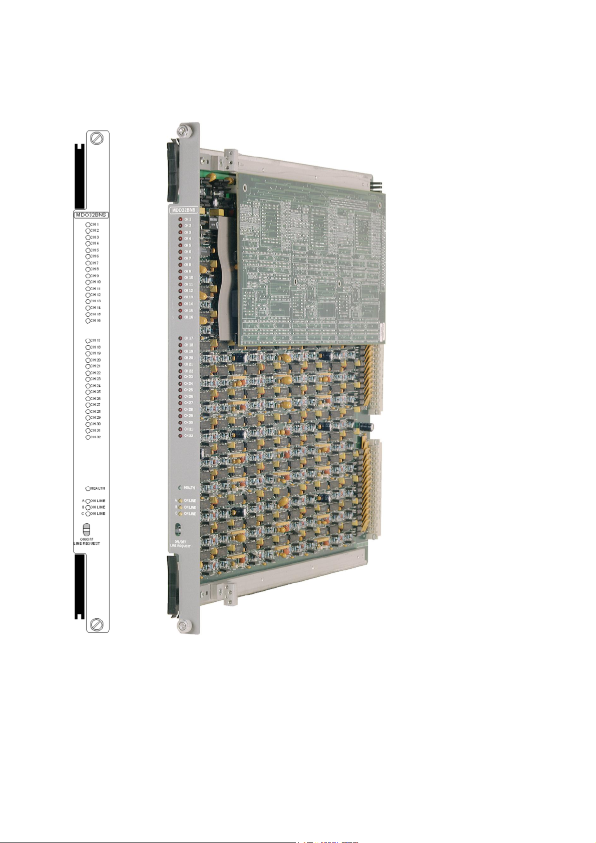
Figure 1-1. MDO32BNS General view and front panel detail
Connector J3
Mechanical coding block
(Lower)
Page 3
MDO32BNS October
2005–
Issue 7
3
Triguard
SC300E MDO32BNS 32-Channel Digital Output Module
ASSOCIATED DOCUMENTATION
Reference No
008-5097
008-5135
008-5179
SPECIFICATION
Model
Channels
Architecture
Indicators:
Output driver
Voltage range
Input:
Module:
Title
Chassis User Manual
TDO16AIN Digital Output Termination Card, DIN to Screw
Terminal Introduced Power User Manual
TDO16BIN Digital Output Termination Card DIN to DIN, Introduced
Power User Manual
MDO32BNS
32
TMR
One per channel
Health, 3 x On Line
FED
18 to 30Vdc (24V nominal)
Voltage drop
Maximum drive
Output rating
Surge
Isolation
Leakage current
Maximum load resistance
Module power consumption excluding field
power dissipation in module
Less than 2Vdc
1A per channel
0.01A minimum @ 24Vdc, 1.0A maximum @
24Vdc (continuous)
Note: The minimum current increases to
0.02A
@ 24Vdc when configured as a dual slot hot
repair
2,5A per channel/second 1% duty cycle
1kVdc system, commoned supply
10mA per channel per module (i.e 20mA when
configured
4.7k ohm (of adequate wattage) for unused
channels
1.2k ohm (of adequate wattage) for all other
conditions
4W
as
dual slot hot repair)
Page 4
4
MDO32BNS
Oc
tober
2005–
Issue 7
Triguard
Model
SC300E
MDO32BNS
Module power
consumption including
power dissipation in
field
module
Overall size (mm) Overall
size
Weight
(inches)
19W @ minimum load
59W @ maximum load
400(9U)H x 397L x 28W
15.75H x 15.63L x 1.1W
1.8kg
ENVIRONMENTAL SPECIFICATION
The maximum ambient temperature measured at the hottest point within the Triguard system
shall
not be greater than 60 degrees centigrade.
Temperature operating:
T
emperature storage:
Humidity
EMC/RFI
Vibration/Shock
Immunity
+5°C to +60°C
-
25°C to +70°C
5% to 95% non-
Tested and certified to IEC 1131-Part 2 1994
Tested and certified to IEC 1131-Part 2 1994
condensing at ambient <40°C
Certification:
General Certification: Ref. SC300E Product Guide (ref 008-5209)
TRANSPORT AND HANDLING
The MDO32BNS must be transported and stored in its original packing material which should be
retained for this purpose
Page 5
MDO32BNS October
2005–
Issue 7
5
Triguard
SC300E MDO32BNS 32-Channel Digital Output Module
TECHNICAL DESCRIPTIO
N
PHYSICAL
The Digital Output Module is a 9U high PCB with integral front panel and rear connectors; a
plug-in daughter board carries the Common Interface circuits. The general layout, location of
connectors, front panel components and the configuration links are shown in Figure 1-1
the
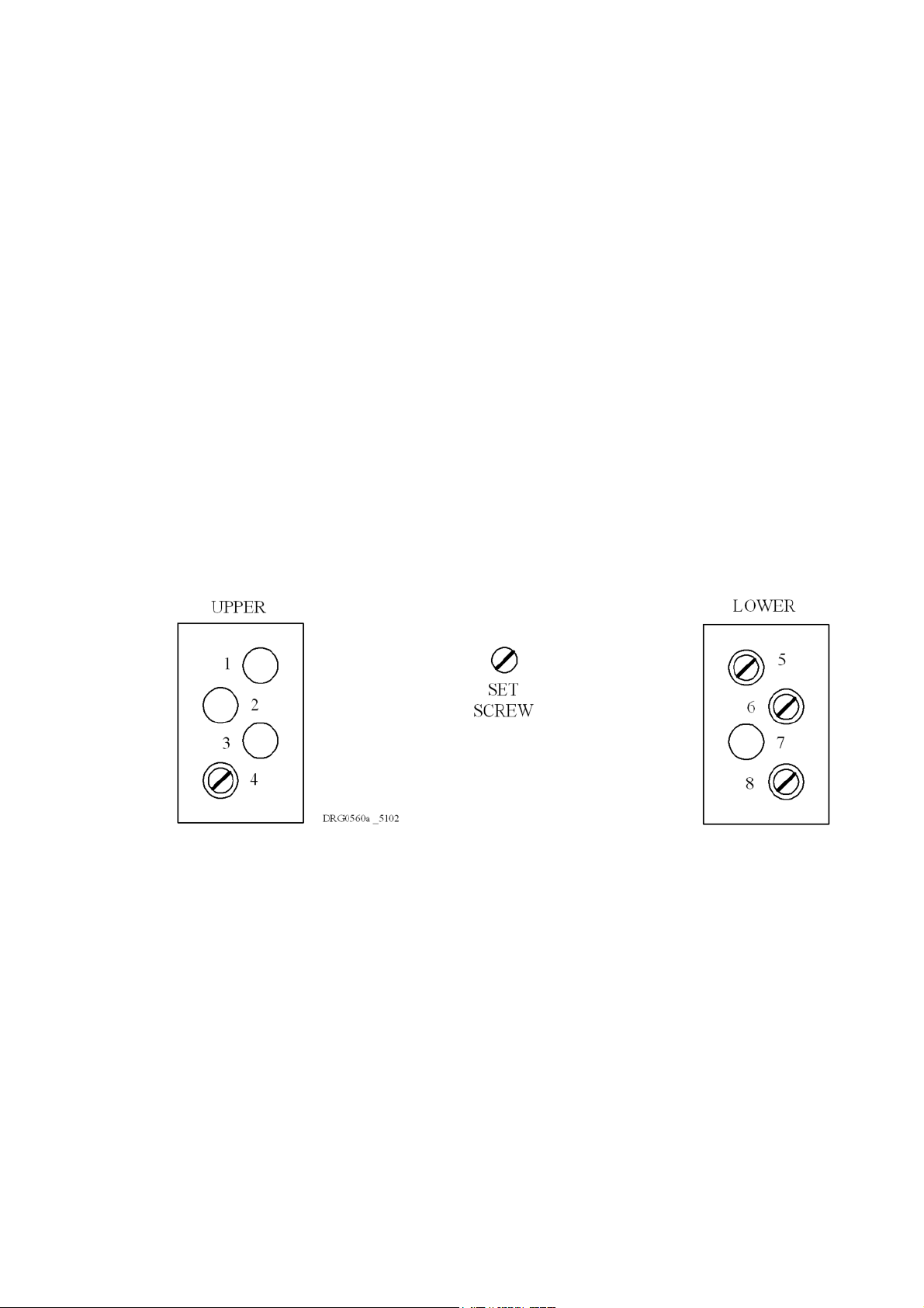
MECHANICAL CODING BLOCKS
All Input/Output modules carry two mechanical coding blocks equipped with pins which mate
with holes in corresponding blocks in the chassis and prevent the module being inserted into
the
wrong slot. The pins in the module blocks are factory installed in a pattern determined by
the module and corresponding set screws are removed from the chassis coding blocks to
enable fitting. Unused holes are plugged with set screws. The chassis coding block
configuration for this module is shown in Figure 2-1.
Figure 2-1. Chassis mechanical coding block configurations
EXTERNAL CONNECTIONS
Field circuits
The field load circuit shown in Figure 2-2 is the absolute minimum required for the safe
connection of field loads to the Digital Output Module. For any unused channel which may
never be switched on a dummy field load (4.7k ohm resistor of adequate wattage) must be
used. If a channel may be switched on, the total load should not exceed 1.2 k ohm maximum.
We
however, recommend the use of their 16 Channel Digital Output termination cards
TDO16*IN which offer full connection facilities with indicating fuses, alarm outputs and dummy
(see Associated documentation).
loads
Page 6

6
MDO32BNS
Oc
tober
2005–
Issue 7
Triguard
SC300E
Page 7

MDO32BNS October
2005–
Issue 7
7
Triguard
SC300E MDO32BNS 32-Channel Digital Output Module
Figure 2-2. Basic field load circuit
Module connectors
The System bus connector is J1 and the Common Interface is connected via J4 and J5 (not shown). In
the
external connection diagram
(Figure 2-3) the following symbols are used:
0
x
GND
+ve
-
ve
O/P
=
=
=
=
=
=
First mate (long pin)
Connector pin
Connected to chassis
Field supply in
Field supply return
Channel output
Page 8

8
MDO32BNS
Oc
tober
2005–
Issue 7
Triguard
SC300E
Figure 2-3. Field output connectors J2 and J3 pinouts
THEORY OF OPERATION
In accordance with TMR practice, channel output command information from the system
follows three identical paths through the Digital Output Module (Figure 2-4) each path at the
command
module
entering the module from the Common Interface. In this manner 32 output channels can be
served by just three paths instead of 96.
The three data streams are each applied to opto-isolators which mark the interface between
the system and output sides of the circuit and provide a system to field channel isolation of
1000V minimum.
The data streams are then applied to the 32-bit output shift registers. The serial bits are
clocked successively into the shift registers until the 32nd bit has been received, the registers
then latch the data and present it on the 32-bit buses (CHANA, CHANB and CHANC) to t
output switches. The data is refreshed in this manner at each scan of the system.
of
its own m
exceeds the system scan rate the channel data can be converted to serial form before
icrocontroller in the Common Interface. As the switching speed of the
he
Page 9
MDO32BNS October
2005–
Issue 7
9
Triguard
SC300E MDO32BNS 32-Channel Digital Output Module
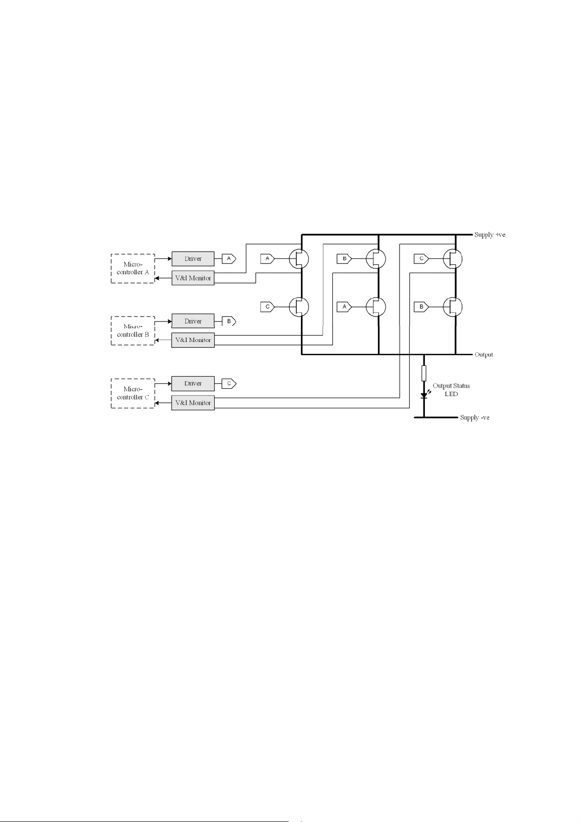
The output switch for each channel comprises six FETs connected in the series/parallel
network shown and providing 2 out of 3 majority voting between the three paths A, B and C.
A front panel LED at the switch output is lit when the switch is closed. Voltage and current
monitoring circuits are also connected to the switches to provide outputs for the Latent Fault
Detection
and opto-isolators. The feedback information confirms that the output has switched to the
commanded state and that the line is not open or short circuit
(LFD) system, these are fed back to the microcontrollers via dedicated shift registers
Figure 2-4. FET ‘hex’ voter
Testing of the output switches using the LFD circuits is co-ordinated by the microcontrollers.
When all outputs are in the healthy condition and the microcontrollers confirm no faults present
the
main processors will instruct each microcontroller in turn to switch its output alone to t
opposite state and confirm the correct operation of the output switch. This test also checks the
integrity
The module power requirements are served from two different sources. The power rails and
reference
the
from
that
of
the output loops for open circuit conditions.
levels for the system-side circuits are derived from the 5.4V and 12V supplies from
system chassis. The power rails and reference levels for the output-side circuits are derived
the field supplies and also serve to confirm that the field circuits are in working order
An On/off Line Request switch on the front panel enables a request to be sent to the system
the module be taken off-line for maintenance purposes or returned on-line.
he
Page 10

10
MDO32BNS
Oc
tober
2005–
Issue 7
Triguard
SC300E
The module uses hardware circuitry and configuration links
the module type and configuration mode. The configuration links 1, 2 and 3 are located in the
top
right-hand corner of the module (see Figure 1.1).
Link 1 allows the module to be set up for 321 or 320 mode operation. 320 mode means that the
system will continue to function with two out of three serviceable circuits. In 321 mode the
system will continue to function with one out of three serviceable circuits. No link; defaults to
320 mode.
Link 2 (HLV/GTZ) determines whether, in the event of a failure due to 321/320 action, the last
read
Link 3 is factory set to HW and if changed to ICCB (see Note) or removed the module defaults
to GTZ.
(NOTE:
values are held (HLV) or are set to zero (GTZ). No link; defaults to GTZ mode.
ICCB is a silk screen identifier used on output modules only)
Table 2-1. Link settings versus operation
that enable the system to identify
Link settings (see Notes)
Link 1
321
320
320
320
320
Notes:
X = Don’t care or missing link
Link 1 missing =
HL = Last valid output held (Output maintained) GTZ = Go To Zero (Output turned off)
Link 2
X X
HLV
HLV
GTZ
Missing
320 operation
Link 3
HW
ICCB
X
X
3 MPPs & associated
path CI operating
Normal Normal Normal
Normal Normal
Normal Normal
Normal Normal
Normal Normal
Processor and interface status
2 MPPs & associated
path CI operating
1 MPP & associated
path
CI
operating
HLV
GTZ
GTZ
GTZ
Page 11

MDO32BNS October
2005–
Issue 7
11
Triguard
SC300E MDO32BNS 32-Channel Digital Output Module
Page 12

12
MDO32BNS
Oc
tober
2005–
Issue 7
Triguard
SC300E
Page 13

MDO32BNS October
2005–
Issue 7
13
Triguard
SC300E MDO32BNS 32-Channel Digital Output Module
COMMON INTERFACE
The three discrete control circuits in the Common Interface (A, B, and C) (Figure 2-6) are each
responsible for the control of the corresponding one third of the I/O module circuits. Each
control circuit comprises a microcontroller with a dedicated watchdog, data buffers and shared
RAM.
The circuit is powered via the module and permits live insertion of replacement modules.
Th
e microcontrollers co-ordinate I/O signal processing, signal path diagnostics, on-line/off-line
status and signal status read/write cycles to and from the system processors via an I/O
communications
Common
determined by the MPPs. If, for maintenance purposes, the On/Off Line Request switch on the
front
passed
extinguishes the Health LED on the I/O module front panel in the event of a microcontroller
failure, LFD failure, a voting discrepancy, loss of field supply or open circuit conditions.
of
the module is operated, the action is read by all three microcontrollers and the request
to
bus. All I/O modules have an identification code which is read by the
Interface and passed to the MPPs for verification. The on-line/off-line status is
the MPPs which may then grant the request. The watchdog on each microcontroller
SYSTEM CONFIGURATION
The Digital Output module requires a ‘dual-slot hot repair’ configuration in order to maintain any
normally energised field loops during repair. We recommend that the ‘dual-slot hot
configuration
hot repair slot to be populated. If the hot repair partner module is fitted during normal operation,
the
output module pair should be de-rated by 50%; unless forced air-cooling is used.
is
used for all output modules. The ‘dual-slot’ configuration does not require the
repair’
NOTE
Fitted Hot Repair partner modules should be bought on-line as part of a regular maintenance
cycle to allow full diagnostic reporting for both modules.
The Digital Output module has a relatively high power dissipation which places some
constraints on its use in convection cooled systems. As each Digital output module will
dissipate 59W when run at full capacity we recommend that these modules are configured in
the lowest chassis within each cabinet bay. If Digital Output modules are configured in slots
located above a fully loaded Digital Output module we recommend that the module is de
rated by 50%. When forced air-cooling is applied to a system to aid heat dissipation then
these
limitations are removed. When c
the maximum working temperature of 60 C is not exceeded in the applications maximum
ambient conditions.
onfiguring a system care should be taken to ensure that
-
Page 14

14
MDO32BNS
Oc
tober
2005–
Issue 7
Triguard
SC300E
Figure 2-6. Common interface -
Block diagram
Page 15

MDO32BNS October
2005–
Issue 7
15
Triguard
SC300E MDO32BNS 32-Channel Digital Output Module
SERVICING
SCOPE
System repair is by mod
be
should
CAUTION 1
The module contains components that may be electrostatically sensitive. It should be
transported and stored in its original packaging material.
CAUTION 2
Before fitting a new module ensure that the setting of all three links is the same as that on the
old
replaced by new modules and returned for repair.
module.
ule replacement. Faulty modules are not repairable in the field; they
DIAGNOSIS
The TriBuild workstation is used for fault diagnosis. In the case of an Input/Output fault the
Health LED on the faulty module will be extinguished
Preparation
To ascertain whether the chassis I/O slot containing the faulty module has been allocated a
hot repair partner use one of the following methods:
• Check the system drawings
• Check the chassis wiring configuration
• Use the I/O chassis configuration report on the TriBuild workstation.
Where there is a Hot Repair partner allocation, use the ‘dual-slot hot repair’ procedure;
otherwise use the ‘single-slot hot repair’ procedure.
Configuration
The only configuration necessary is the correct setting of the three links which are shown in
Figure 1-1. Ensure that the link configuration on the new module is the same as that on the old
module.
Page 16

16
MDO32BNS
Oc
tober
2005–
Issue 7
Triguard
SC300E
Removal and replacement
CAUTION
Failure to take the faulty module off-line before removing it from the chassis could trigger a fault
alarm
CAUTION 4
When inserting a module ensure that it is aligned with the markings on the chassis rails and
that it engages w
module
Single-slot hot repair
Operate the On/Off Line Request switch on the faulty module, the three On Line LEDs should
all go out to indicate that the M
The
Slacken the two module securing screws and use the black ejection levers (top and bottom) to
draw
I
nsert the new module ensuring that it engages properly in the upper and lower guides in the
chassis, the top and bottom chassis rails carry alignment marks to assist. Pull out the
ejection levers and as the module is pushed back engage the levers on the ch
levers should then be used to draw the module into position, some resistance will be felt as the
rear
3
or
cause plant shutdown .
ith the upper and lower guides. Improper insertion may cause damage to the
and/or chassis connectors.
PPs have recognised the request and taken the module off-line.
outputs will be de-energised until the new module is on-line.
the module from its slot.
connector pins engage. The module should be fixed in position with the securing screws.
assis rails. The
Operate the On/Off Line Request switch and check that the three On Line LEDs illuminate for
one second, extinguish for one second and then illuminate permanently to indicate that the
module has been put on-line. All outputs that are required to be energised by the system logic
will
be re-
energised. If the
illuminated,
NOTE
If the replacement board comes on-line but the health LED is extinguished a fault still exists. If
the
failure is LFD this may indicate a field fault (open circuit) and the field loops should be
investigated.
then the module must be considered faulty.
LEDs do not illuminate either the first or second time or fail to remain
Page 17

MDO32BNS October
2005–
Issue 7
17
Triguard
SC300E MDO32BNS 32-Channel Digital Output Module
Dual-slot hot repair
Insert the new module into the vacant hot repair slot ensuring that it engages properly in the
upper
and lower guides in the chassis, the top and bottom chassis rails carry alignment marks
to assist. Pull out the black ejection levers and as the module is pushed back engage the
levers on the chassis rails. The levers should then be used to draw the module into position,
some resistance will be felt as the rear connector pins engage. The module should be fixed in
position
Operate the On/Off Line Request switch on the new module. Ascertain that the three On Line
LEDs on the new module illuminate for one second, extinguish for one second and then
illuminate permanently as the LEDs on the old module extinguish. This sequence indicates
that the new module has been put on-line and the old module taken off-line. If the LEDs on the
new module do not illuminate either the first or second time or fail to remain illuminated, the
new module must be regarded as faulty. The old module LEDs should remain illuminated
indicating that it is still on-line.
If the new module is serviceable slacken the screws on the old module and use its ejection
levers to remove it from the Chassis.
NOTE
If the replacement board comes on-line but the health LED is extinguished a fault still exists. If
the failure is LFD this may indicate a field fault (open circuit) and the field loops should be
investiga
with the securing screws.
ted.
Page 18

18
MDO32BNS
Oc
tober
2005–
Issue 7
Triguard
SC300E
PREVENTIVE MAINTENAN
No preventive maintenance is necessary.
SERVICE SUPPORT
Spare parts and technical advice can be obtained from your local area office
CE
.
 Loading...