

Page 1

Triguard SC300E
MAI32*AD
32-Channel Analogue Input Module
Differential
Issue 4
INTRODUCTION
PURPOSE
The Analogue Input Module provides up to 32, low voltage or current analogue input signals. All
channel
from
inputs into the module are resistively isolated from each other and galvanically isolated
the system environment.
Input
(MAI32*AD
October 2005
)
The basic module can be configured to meet a range of input specifications, the different
configurations can be identified from the module type number (see Section 1.3, Specification)
Circuit triplication and voting procedures make the module single-fault tolerant. A front panel
Channel selector and test points enable the metering of any channel, and indicators show the
circuit on-line status and the health of the module.
The module, which is compatible with ‘hot repair’, can be fitted in any of the ten I/O slots in the
SC300E Chassis, ‘wrong slotting’ is prevented by physical coding. The SC300E system
software identifies the module via a built-in hardware identifier.
Channel inputs are wired to the module via the DIN 41612 ‘rear plug-up’ system on the chassis
backplane. This document is intended to provide a general understanding of the function of the
Analogue
field.
Input Module, sufficient to enable basic maintenance operations to be eff
ASSOCIATED DOCUMENTATION
Reference No Title
008-5097
Chassis User Manual
ected in the
.
008-5102
008-5155
008-5156
TAI16AEA Termination Card Analogue Input
DIN to screw User Manual
TAI16AIR Termination Card Analogue Input
DIN
to
screw, 250 Ohm terminated, Internal
power, User Manual
TAI16BIRTermination Card Analogue Input DIN
008-5103
Page 2
2
MAI32*A
D
October
2005–
Issue 4
Triguard
SC300E
to DIN, 250 Ohm terminated, Internal power,
User Manual
Mechanicalcodin
gblock(Upper)
321/320 Link
321 320
ConnectorJ1
Common
Interface (CI)
( on dau g ht er board)
Connector J2
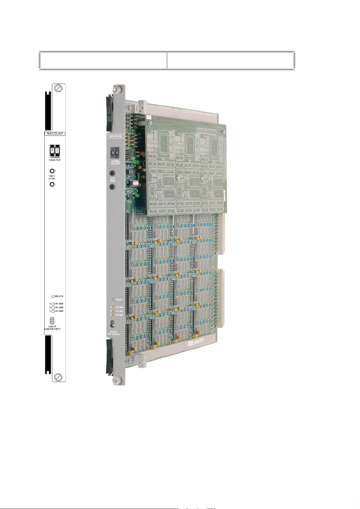
Figure 1-1 General view and front panel detail
Connector J3
Mechanical coding
block (Lower)
Page 3

MAI32*A
D
October
2005–
Issue 4
3
Triguard
SC300E
SPECIFICATION
MAI32*AD
32-Channel A/I Module Differential Input
Input parameters
All models have 32 input channels configured as follows:
Model number
MAI32LAD
MAI32MAD
0 to 20mA. Use TAI16AIR (BIR) with MAI32LAD
0 to 40mA Use TAI16AIR (BIR) with MAI32MAD
Channels
Architecture
Indicators
Channel Input Test Ponts
Input range
Input overrange protection
Current input applications
Model
Voltage input applications
0 to 5Vdc
0 to 10Vdc
32
TMR
Health 3 x On Line
Switch selectable on front panel
MAI32LAD
MAI32MAD
±40Vdc
See under “input range”
: 0 to 5Vdc
: 0 to 10Vdc
Resolution
Accurancy @ 25°C
Stability (temperature coefficient)
Analogue to digital converter
Sample rate
Input impedance
Power off impedance
Common mode range
Isolation
Power consumption
By system
By input loads
Overall size (mm)
Overall size (inches)
Weight
12 bits
±
0.04% over full signal range
±20ppm/°C
SAR (monotonic)
40ms nominal
>20M ohm
>12k ohm
±11Vdc
1kVdc system/channel
±15Vdc channel to channel
7.5W excluding input loads
3.2W maximum for 20mA module
400(9U)H x 397L x 28W
15.75H x 15.63L x 1.1W
1.6kg
Page 4

4
MAI32*A
D
October
2005–
Issue 4
Triguard
SC300E
Page 5

MAI32*A
D
October
2005–
Issue 4
5
Triguard
SC300E
MAI32*AD
32-Channel A/I Module Differential Input
NOTE
For voltage loop inputs TAI16AEA termination cards must be used
ENVIRONMENTAL SPECIF
The maximum ambient temperature measured at the hottest point within the Triguard system
shall
not be greater than 60 degrees centigrade.
Temperature operatin
Tem
perature storage
Humidity
EMC/RFI
Vibration/Shock
Certification:
General Certification: Ref. SC300E TMR Product Guide (ref 008-5209)
Immunity
g
ICATIONS
+5°C to +60°C
-
25°C to +70°C
5% to 95% non-condensing at ambient <40°C
Tested and certified to IEC 1131-Part 2 1994
Tested and certified to IEC 1131-Part 2 1994
TRANSPORT AND HANDLING
The MAI32*AD must be transported and stored in its original packing material which should be
retained
for this purpose.
Page 6

6
MAI32*A
D
October
2005–
Issue 4
Triguard
SC300E
TECHNICAL DESCRIPTIO
N
PHYSICAL
The Analogue Input Module is a 9U high PCB with integral front panel and rear connectors; a
plug-in daughter board carries the Common Interface circuits.The general layout, location of the
connectors,
front panel components and the 321/320 configuration link is shown in Figure 1-1.
Mechanical coding blocks
All Input/Output modules carry two mechanical coding blocks equipped with pins which mate
with
holes in corresponding blocks in the chassis and prevent the module being inserted into
the wrong slot. The pins in the module blocks are factory installed in a pattern determined by
the module and corresponding set screws are removed from the chassis coding blocks to
enable
block configuration for thi
fitting. Unused holes are plugged with set screws. The chassis mechanical coding
s module is shown i
n Figure 2-1
.
Figure 2-1 Chassis mechanical coding block configurations
EXTERNAL CONNECTIONS
Field circuits
The field input loop shown in Figure 2-2 is the absolute minimum required for the safe
connection
Analogue Input termination cards TAI16*** which can offer field power supplies, remote and
local
alarm indication, transient suppression and signal and protective ground facilities.
Figure 2-3 shows a termination card for a current input module.
of
analogue inputs. We however, recommend the use of their 16 Channel
Page 7

MAI32*A
D
October
2005–
Issue 4
7
Triguard
SC300E
MAI32*AD
32-Channel A/I Module Differential Input
Figure 2-2 Basic field input circuit
Figure 2-3 Field input using Termination Card
Page 8

8
MAI32*A
D
October
2005–
Issue 4
Triguard
SC300E
Figure 2-4 Field input connectors J2 and J3 pinouts
Module connectors
The System bus connector is J1 and the Common Interface is connected vi
shown). In the external connection diagram Figure 2-4 the following symbols are used:
= First Mate (long pin)
x = Connector pin
0V
=Instrumentation Earth
a J4 and J5 (not
Page 9

MAI32*A
D
October
2005–
Issue 4
9
Triguard
SC300E
MAI32*AD
32-Channel A/I Module Differential Input
THEORY OF OPERATION
Analogue input module
The first part of the block diagram in Figure 2-5 shows the circuit used to process one of the 32
analogue inputs. The field input is connected across a ranging resistor which is selected in
accordance with the type of field input to be processed (current or voltage). The channel signal
is then distributed along four paths (A to D); paths A, B and C are the triplicated signal
processing circuit and path D feeds the metering test point.
In each path the signal is first passed through RF and low-pass filters before being applied to
one channe
microcontroller in the Common Interface is isolated, decoded and used to select which input
channel
and sent to an analogue to digital (ADC) converter which produces a serial data output coded
to represent the amplitude of the channel input signal. Factory set links connected to the ADC
enable the basic module to be configured for different +5Vdc o
ADC
output is passed via an opto-isolator to the Common Interface for processing.
l of a 32 channel multiplexer. For paths A, B and C a command from the
will be switched to the output of the multiplexer. The multiplexer output is then buf
fered
r +10Vdc voltage ranges. The
There is no ADC in path D, the buffered signal is applied directly to the metering test point on
the front panel. Channel selection is by means of the adjacent channel selector switches.
Power to the module is 5.4Vdc and 12Vdc supplied by each of the dual redundant SC300E
power supply units. Each line is divided into four branches to provide a supply to each of the
four paths. The dual inputs for both supplies (12V and 5.4V) in each branch are ORed via
diodes to provide the dual redundancy. After filtering and surge limitation the output rails VEE*
(nominally12V)
C 5V rails
Each of the A, B and C path supplies is also continuously monitored and the monitor outputs
A/PSUOK, B/PSUOK and C/PSUOK are sent via the Common Interface to the MPPs for
d
iagnostic purposes.
An On/off Line Request switch on the front panel enables a request to be sent to the MPPs
that the module be taken off-line for maintenance purposes.
The module contains a hardware identity circuit that enables system identification o
module.
Links
Only user changeable link is identified as LK3 and located in the top right hand corner of the
module
(see Figure 1-1). The link (LK3) enables the module to be set for 321 or 320 mode.
and VCC* (nominally 5V) provide power to their respective paths. The A, B and
also supply power to the corresponding control circuits in the Common Interface.
f the
Modes of operation
The 321 or 320 mode sets the threshold that determines how much of the circuit can be
degraded while still preserving overall operation. Setting the 320 mode means that the system
will
continue to function with two out of three serviceable circuits; if the number falls to one out
of th
ree the last read data is maintained. In 321 mode the system will continue to function with
one out of three serviceable circuits; if that fails the last read data is maintained and the
module is taken off-line.
Page 10

10
MAI32*A
D
October
2005–
Issue 4
Triguard
SC300E
Page 11

MAI32*A
D
October
2005–
Issue 4
11
Triguard
SC300E
MAI32*AD
32-Channel A/I Module Differential Input
Figure 2-5 Analogue input module-Block
diagram
Page 12

12
MAI32*A
D
October
2005–
Issue 4
Triguard
SC300E
Common interface
The three discrete control circuits in the Common Interface (A, B, and C) are each responsible
for the control of the corresponding one third of the I/O module circuits. Each control circuit
comprises a microcontroller with a dedicated watchdog, data buffers and shared RAM. The
circuit is powered via the module and permits live insertion of replacement modules.
Figure 2-6 Common interface -
The microcontroller co-ordinates I/O signal processing, signal path diagnostics, on-line/off-line
status and signal status read/write cycles to and from the MPPs via an I/O communications
bus. All I/O modules have an identification code which is read by the Common Interface and
passed to the MPPs for verification. The on-line/
maintenance purposes, the On/off Line Request switch on the front of the module is
operated, the action is read by all three microcontrollers and the request passed to the MPPs
which may then grant the request. The watchdog extinguishes the Health LED on the I/O
module front panel in the event of a microcontroller failure, LFD action or a voting discrepancy.
off-
Block diagram
line status is determined by the MPPs. If,
for
Page 13

MAI32*A
D
October
2005–
Issue 4
13
Triguard
SC300E
MAI32*AD
32-Channel A/I Module Differential Input
SERVICING
SCOPE
System repair is by module replacement. Faulty modules are not repairable in the fi
should be replaced by new modules and returned for repair.
CAUTION 1
Before fitting a new module ensure that the 321/320 link setting is the same as that on the old
module.
The module contains components that may be electrostatically sensitive, it should be
transported and stored in its original packaging material.
CAUTION 2
eld, they
DIAGNOSIS
The TriBuild workstation is used for fault diagnosis. In the case of an Input/Output fault the
Health LED on the faulty module will be extinguished.
CAUTI
ON 3
Do not use a mains-powered multimeter on the front panel test points.
CONFIGURATION
The only configuration necessary is the correct location of the 321/320 Link as shown in Figure
1-1 Ensure that the link configuration on the new module is identical to that on the old module.
REMOVAL AND REPLACEMENT
Preparation
Before removal /replacement ascertain if the module under consideration is used in the single
or dual hot repair configuration.
Failure to take the faulty module off-line before removing it from the chassis could trigger a fault
alarm
or
cause plant shutdown.
CAUTION 4
Page 14

14
MAI32*A
D
October
2005–
Issue 4
Triguard
When inserting a module ensure that it is aligned with the markings on the chassis rails and
that
it
module
SC300E
engages with the upper and lower guides. Improper insertion may cause damage to the
and/or chassis connectors.
CAUTION 5
Single-slot hot repair
Operate the On/Off Line Request switch on the faulty module, the three On Line LEDs should
all go out to indicate that the MPPs have recognised the request and taken the module offThe last read data input from the module will be maintained until the new module is on-line.
Slacken
draw
Insert the new module ensuring that it engages properly in the upper and lower guides in the
chassis, the top and bottom chassis rails carry alignment marks to assist. Pull out the
ejection levers and as the module is pushed back engage the levers on the chassis rails. The
levers
rear
Operate the On/Off Line Request switch and check that the three On Line LEDs illuminate for
one second, extinguish for one second and then illuminate permanently to indicate that the
module has been put on-line. If the LEDs do not illuminate either the first or second time or fail
to remain illuminated, then the module must be considered faulty.
the two module securing screws and use the black ejection levers (top and bottom) to
the module from its slot.
should then be used to draw the module into position, some resistance will be felt as the
connector pins engage. The module should be fixed in position with the securing screws.
Dual-slot hot repair
Insert the new module into the vacant hot repair slot ensuring that it engages properly in the
upper
and lower guides in the chassis, the top and bottom chassis rails carry alignment marks
to assist. Pull out the eject
the chassis rails. The levers should then be used to draw the module into position, some
resistance
position with the securing screws.
will be felt as the rear connector pins engage. The module should be fixed in
line.
ion levers and as the module is pushed back engage the levers on
Operate the On/Off Line Request switch on the new module. Ascertain that the three On Line
LEDs on the new module illuminate for one second, extinguish for one second and then
illuminate permanently as the LEDs on the old module extinguish. This sequence indicates
that the new module has been put on line and the old module taken off line. If the LEDs on the
new
module do not illuminate either the first or second time or fail to remain illuminated, the
new module must be regarded as faulty. The old module LEDs should remain illuminated
indicating
If the new module is serviceable slacken the screws on the old module and use its ejection
levers to remove it from the chassis.
PREVENTIVE MAINTENAN
No preventive maintenance is necessary.
that it is still on-line.
CE
Page 15

MAI32*A
D
October
2005–
Issue 4
15
Triguard
SC300E
MAI32*AD
32-Channel A/I Module Differential Input
SERVICE SUPPORT
SPARE PARTS
Spare parts and technical advice can be obtained from the your local area office.
 Loading...