

Page 1
Snubber Braking Kits for A C Drives
Enclosed Resistor Modules, Enclosed Transistor Modules
Model Numbers
M3575RH__, M3575RL__, M3575TH__, M3575TL__
Instruction Manual D2-3439-1
ATTENTION:Only qualified electrical personnel familiar with the construction and operation of
this equipment and the hazards involved should install, adjust, operate, and/or service this
!
Product Description
Snubber Braking kits connect to 230 VAC and 460 VAC GV3000/SE, SP120, SP500, and VSM500 drives.
These kits dissipate the power regenerated by the motor during rapid deceleration or during overhauling load
conditions.
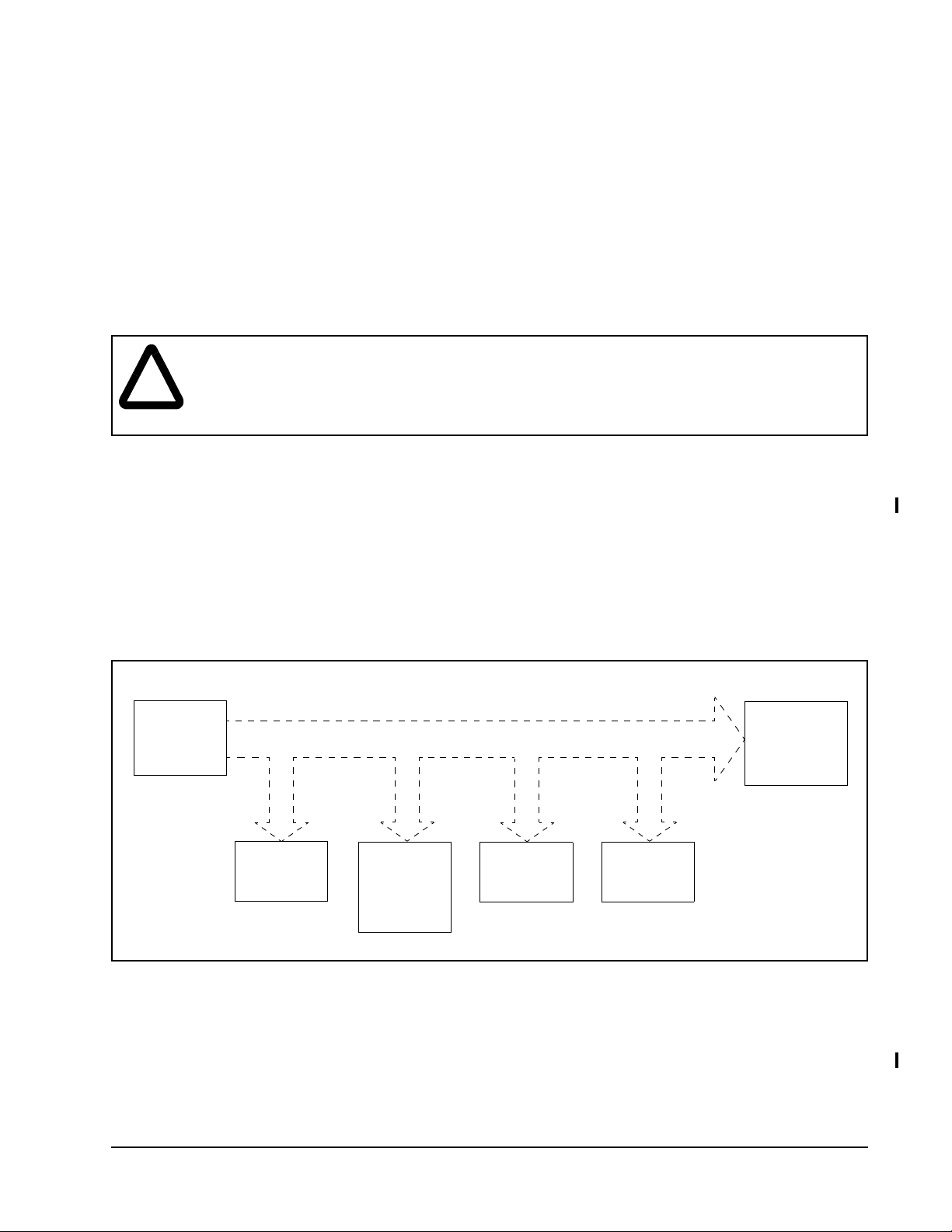
The regenerated energy is normally consumed, as shown in figure 1, by mechanical loss, by the motor, and by
the drive. The remaining energy is stored in the drive’s DC bus capacitor. If the remaining energy causes the
capacitor voltage to rise above the normal operating range, the Braking Unit will discharge the regenerated
energy before the drive voltage becomes excessive.
equipment. Read and understand this manual and other applicable manuals in their entirety
before proceeding. Failure to observe this precaution could result in severe bodily injury or loss
of life.
Energy
Regenerated
by t h e Moto r
Consumption
by Mechanical
Loss
Consumption
in th e Mo to r
Itself (approx.
10 to 20% of
Output
Figure 1 – Dissipation of Energy Regenerated by the Motor
Consumption
by the Drive
Itself
Storage in
Capacitor of
the Drive
Discharge of
Regenerated
Energy at
Braking Unit
Power resistors are used to dissipate the energy. When the DC bus voltage rises above normal level, either a
built-in transistor (in GV3000/SE bookshelf drives) or an external transistor (used with NEMA-type GV3000/SE,
SP500, and VSM500 drives) automatically switches the dynamic braking resistors on in
pulse-width-modulation (PWM) mode to absorb the excess energy. The transistor is turned fully on at 375 VDC
for 230 VAC input drives and at 750 VDC for 460 VAC input drives. The snubber resistors are sized to provide
the power dissipating capability required for the duty cycle of the application.
Snubber Braking Kits for AC Drives
1
Page 2
Snubber Braking kits are available:
• as an Enclosed Resistor module for use with an AC drive containing a built-in transistor switching circuit
(such as the GV3000/SE Bookshelf AC drive) or for use in conjuction with an enclosed transistor module
(M/N M3575T__)
• as an Enclosed Tr ansistor module (M/N M3575T__) for use with AC drives that do not contain a built-in
transistor switching circuit and for use with the enclosed resistor modules (M/N M3575R__)
Note that all of the Enclosed Resistor modules and Enclosed Transistor modules are rated for a maximum
on-time of 60 seconds at a specified duty cycle (see tables 1, 2, 5 and 6).
For GV3000/SE Bookshelf drives: Refer to tables 1, 2, and 3 to ensure that the Enclosed Resistor kit
matches your drive.
For AC Drives requiring both an Enclosed Resistor kit and an Enclosed Transistor kit: Refer to tables 4,
5, and 6 to ensure that the braking kits match your drive and your braking horsepower requirements.
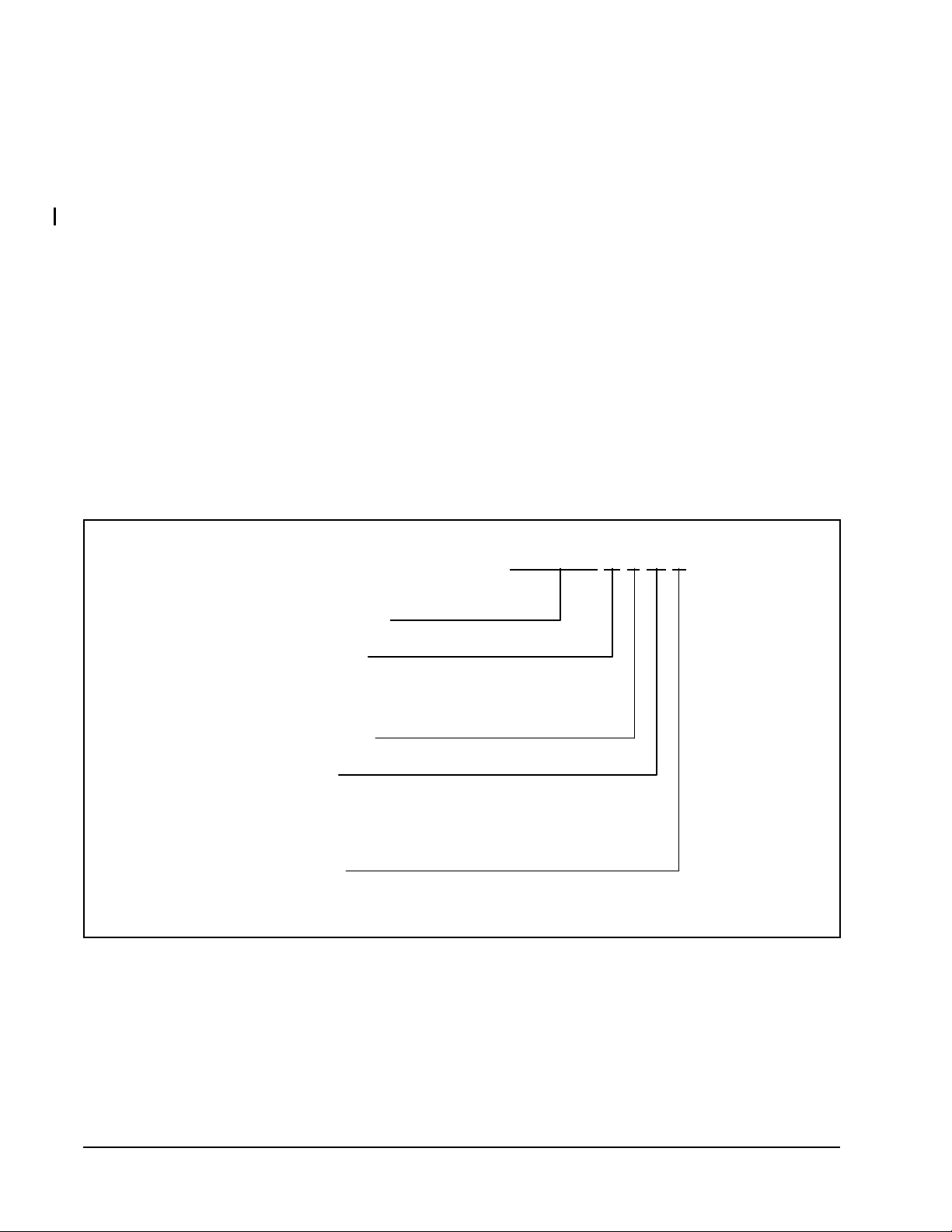
Snubber Resistor Kits (M3575RH__, M3575RL__)
The figure below depicts the breakdown of the Snubber Resistor kit part number.
M3575R H 2 M F
Base Model Number
AC Voltage Rating
L = 230 VAC
H = 460 VAC
Horsepower Rating
Chassis Style
B = Bookshelf Style
M = Mini (Standard Enclosed S t y le)
G = Grid Resistors (G1, G2, G3)
Cooling Option
F = Internal Fan
Enclosed Resistor Braking Unit Fault Outpu t
Enclosed Resistor Braking units have one normally-closed contact (NC) rated at 1 amp @ 24 VDC or
0.5 amp @ 115 VAC that opens on an overtemperature fault condition ( 85 C or higher).
2
Enclosed Resistor Modules, Enclosed Transistor Modules
Page 3

Tables 1 and 2 show the rating data for the Enclosed Resistor Braking kits.
Table 1 – Enclosed Resistor Braking Kit Ratings (230 VAC)
Braking Kit
Model Number
M3575RL1M
Braking
HP
1 6%
M3575RL1MF
M3575RL2M
2 6%
M3575RL2MF
M3575RL3B
3 6%
M3575RL3BF
M3575RL3M
36%
M3575RL3MF
M3575RL4M
4 6%
M3575RL4MF
M3575RL5B
56%
M3575RL5BF
M3575RL6M
6 6%
M3575RL6MF
M3575RL8B
86%
M3575RL8BF
M3575RL9M
9 6%
M3575RL9MF
M3575RL11B
11 6%
M3575RL11BF
M3575RL16B
16 6%
M3575RL16BF
M3575RL24B
24 6%
M3575RL24BF
1.
Maximum on-time is 60 seconds.
Braking
Duty
Cycle
20%
20%
20%
20%
20%
20%
20%
20%
20%
20%
20%
20%
Braking Watts
1
746 50
Max.
Amp
Rating
2 190 M4
Load
Ohms
±10%)
(
Enclosure
TypePeak Continuous
150
1492 100
4 95 M4
300
1989 100
5 75 B4
400
2238
150
6 63 M4
450
2984 200
8 48 M7
600
3979 200
10 38 B4
800
4476 300
12 32 M7
900
5968 300
15 25 B4
1200
6714 450
18 21 M10
1350
7967 400
20 19 B7
1600
11936 600
31 13 B7
2400
17904 900
47 8 B10
3600
Enclosed Resistor Modules, Enclosed Transistor Modules
3
Page 4

Table 2 – Enclosed Resistor Braking Kit Ratings (460 VAC)
Braking Kit
Model Number
M3575RH1M
M3575RH1MF
M3575RH2M
M3575RH2MF
M3575RH3M
M3575RH3MF
M3575RH4M
M3575RH4MF
M3575RH5B
M3575RH5BF
M3575RH6M
M3575RH6MF
M3575RH8B
M3575RH8BF
M3575RH9M
M3575RH9MF
Braking
HP
1 6%
2 6%
3 6%
4 6%
5 6%
6 6%
8 6%
9 6%
Braking
Duty
Cycle
20%
20%
20%
20%
20%
20%
20%
20%
Braking Watts
1
746 50
1492 100
2238 150
2984 200
4000 250
4476 300
6000 350
6714 400
150
300
450
600
800
900
1200
1350
Max.
Amp
Rating
Load
Ohms
±10%)
(
Enclosure
1 780 M4
2 390 M4
3 260 M4
4 195 M7
5 150 B4
6 130 M7
8 90 B4
9 87 M10
TypePeak Continuous
M3575RH11B
M3575RH11BF
M3575RH16B
M3575RH16BF
M3575RH24B
M3575RH24BF
11 6%
20%
16 6%
20%
24 6%
20%
8000 450
1600
12000 700
2400
18000 1000
3600
11 60 B7
16 45 B7
24 30 B10
M3575RH50G1F 50 20% 40000 8000 53 14 G1
M3575RH100G2F 100 20% 80000 16000 106 7 G2
M3575RH150G3F 150 20% 120000 24000 159 5 G3
1.
Maximum on-time is 60 seconds.
4
Enclosed Resistor Modules, Enclosed Transistor Modules
Page 5
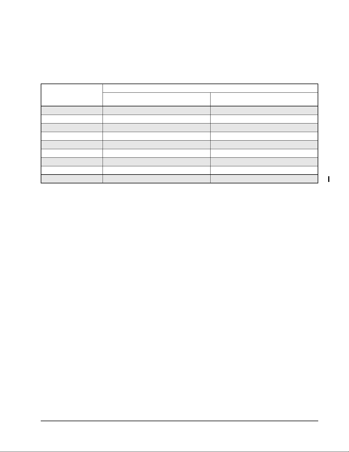
Table 3 shows the acceptable matches, by braking horsepower, between GV3000/SE Bookshelf drives and
Enclosed Resistor Braking kits. For actual sizing information, refer to “Selecting and Sizing Snubber Braing
Resistors” on page 18 of this manual.
Table 3 – Matching Enclosed Resistor Braking Kits with GV3000/SE Bookshelf Drives
GV3000/SE
Can use snubber resistor kits rated at the following braking HP
Bookshelf Drive
Model Number
Volts/Hertz Vector
31ER/31ET4060 1 HP to 3 HP 1 HP to 2 HP
38ER/38ET4060 1 HP to 4 HP 1 HP to 3 HP
55ER/55ET4060 1 HP to 4 HP 1 HP to 4 HP
85ER/85ET4060 1 HP to 6 HP 1 HP to 6 HP
126ER/126ET4060 1 HP to 9 HP 1 HP to 6 HP
150ER/150ET4060 1 HP to 9 HP 1 HP to 8 HP
240ER/240ET4060 1 HP to 11 HP 1 HP to 11 HP
300ER/300ET4060 1 HP to 16 HP 1 HP to 16 HP
430ER/430ET4060 1 HP to 24 HP 1 HP to 24 HP
Enclosed Resistor Modules, Enclosed Transistor Modules
5
Page 6

Sized for 1/4” Bolts or Studs
Enclosure
Type
M3 323,8
M4 323,8
M7 323,8
M10 323,8
B4 450,8
B7 450,8
B10 450,8
.75
A
E
G
F
Terminal Strip
.28 .28
1.00
A BCDEFGH
(12.75)
(12.75)
(12.75)
(12.75)
(17.75)
(17.75)
(17.75)
D
76,2
(3.0)
101,6
(4.0)
177,8
(7.0)
254
(10.0)
101,6
(4.0)
177,8
(7.0)
254
(10.0)
B
Dimension in mm (in)
95,6
(7.70)
95,6
(7.70)
95,6
(7.70)
95,6
(7.70)
95,6
(7.70)
95,6
(7.70)
95,6
(7.7)
n/a 304,8
44,5
(1.75)
127
(5.0)
203,2
(8.0)
44,5
(1.75)
127
(5.0)
203,2
(8.0)
C
H
(12.0)
304,8
(12.0)
304,8
(12.0)
304,8
(12.0)
425,5
(16.75)
425,5
(16.75)
425,5
(16.75)
266,7
(10.5)
266,7
(10.5)
266,7
(10.5)
266,7
(10.5)
381
(15.0)
381
(15.0)
381
(15.0)
28,7
(1.13)
28,7
(1.13)
28,7
(1.13)
28,7
(1.13)
35,1
(1.38)
35,1
(1.38)
35,1
(1.38)
221
(8.7)
221
(8.7)
221
(8.7)
221
(8.7)
221
(8.7)
233,7
(9.2)
246,4
(9.7)
Figure 2 – Resistor Braking Kit Enclosure Dimensions
6
Enclosed Resistor Modules, Enclosed Transistor Modules
Page 7

Front View Side View
29"
Field Connection
Terminals Are
Located Behind
Filte r S c re en
0.56"
25"
2.0"
2.0"
22"
18"
3.5"
A
4.25"
2.5"
B
Foot Print
Dimensions
Chassis Dim.A Dim.B
21.88"
1.0"
0.56"
Figure 3 – Resistor Braking Kit Enclosure Dimensions (Floor-Mount Models)
14.75"
1.63"
.56" X 1.0"
(4 Places)
G1
G2
G3
31"
40"
49"
38.75"
47.75"
47.75"
56.75"
Enclosed Resistor Modules, Enclosed Transistor Modules
7
Page 8

Installing the Enclosed Resistor Braking Kit
ATTENTION:Equipment is at line voltage when AC power is connected to the drive. The drive’s
DC bus capacitors retain hazardous voltages after input power has been disconnected. After
!
Choose the installation site for the Enclosed Resistor Braking Unit with the following considerations in mind:
• The unit must be mounted in a clean, dry environment. The maximum ambient air temperature should not
exceed 40° C (104° F).
• The mounting surface must be non-flammable, as the unit may generate high temperatures during operation.
• The unit requires a minimum clearance of (2 inches) in all directions.
Use the following procedure to install Braking Units housed in NEMA 1 enclosures.
Step 1. Disconnect, lock out, and tag input power to the drive. Wait five minutes for the DC bus capacitors to
disconnecting input power, w ait five (5) minutes for the DC bus capacitors to discharge and then
check the DC bus voltage with a voltmeter to ensure the DC bus capacitors are discharged
before touching any internal components. Failure to observe this precaution could result in severe
bodily injury or loss of life.
ATTENTION:The user is responsible for conforming with all applicable local, national, and
international codes. Failure to observe this precaution could result in damage to, or destruction
of, the equipment.
discharge.
Step 2. Verify that there is no voltage at the drive’s input power terminals.
Step 3. Measure the drive’s DC bus potential with a voltmeter to ensure that the DC bus capacitors have fully
discharged as described in the drive’s instruction manual.
Step 4. Select a location for the Braking Unit within 8 feet of the drive where the heat generated by the
snubber resistors will not affect surrounding components. Do not mount the Braking Unit under the
drive or where convective air flow is restricted.
Step 5. Mount the Braking Unit vertically with the fan at the bottom. Mounting hardware is not provided. See
figure 2 or 3 for mounting dimensions.
Step 6. Install the wiring between the drive and the Braking Unit. See figures 4, 5, and 8. Use wire that is
rated at a minimum of 300 volts for 230 VAC Braking Units and 600 volts for 460 VAC Braking Units.
ATTENTION:It is important to use wire rated at 300 volts for 230 VAC Braking Units (600 volts
for 460 V AC Braking Units) or greater because this wiring may come into contact with uninsulated
!
Step 7. Reapply input power to the drive. Refer to the drive’s instruction manual for complete start-up
230 VAC (or 460 VAC) components. Failure to observe this precaution could result in damage
to, or destruction of, the equipment.
information.
8
Enclosed Resistor Modules, Enclosed Transistor Modules
Page 9

Braking Resistor Unit Field Connection Notes
C
ATTENTION: Only qualified personnel familiar with the construction and operation of this
equipment and the hazards involved should install or service this equipment. The user is
!
Observe the following precautions when making field connections:
• Do not connect the Braking Resistor Unit directly across the DC bus. This would exceed the maximum
duty cyle rating of the load. The extreme overheating generated by the load resistors under this condition
could present a fire hazard in and around the resistive load module.
• Be sure the Braking Resistor Unit being connected meets the minimum load resistance requirements listed
in table 1 or table 2.
• Field connection terminals used on the bookshelf style and standard enclosed style Braking Resistor units
will accept a 10 AWG maximum wire size. Wires should be stripped 0.25”. Crimp-style terminations are not
recommended.
• Wire types and sizes should be chosen in accordance with local, national, and/or international electrical
codes as well as module termination limitations to meet the voltage and current levels present for the
application.
responsible for conforming with all applicable local, national, and international codes. Failure to
observe these precautions could result in personal injury and/or damage to, or destruction of,
the equipment.
M3575R Braking Resistor Unit Field Connections
For Drives With Internal Braking Transistor (such as GV3000/SE Bookshelf drives)
RES RES
12345
NOTES
1.
Temp alarm opens up on a faul t and is rated at 0. 5 amps (115 VAC ).
Refer to drive ins truction manual for d rive con necti ons.
2.
TEMP
ALARM
Se e No te 1
FAN
(
OPTIONAL
115VAC 115VAC
)
6
Ground
Figure 4 – Wall-Mounted Braking Resistor Unit Field Connections
M3575R
To Braking
Module
Ground
+ Brake Out
- Brake Out
(+) 47
(-)
L1
L2
L3
45
48
U
V
W
18 AW G
Motor and Drive
Se e No te 2
115 VA
3 Line
Enclosed Resistor Modules, Enclosed Transistor Modules
9
Page 10

Typical Resistive Load
S ee T e rmin a l S trip D e ta il
12
Resistive Load Connections
1/2" Coarse Threaded Studs
r
e
w
FAN
o
P
n
a
F
.
h
c
t
i
w
S
p
m
e
T
h
p
c
t
m
i
e
w
T
S
r
t
l
e
u
v
a
O
F
#8 Screw Terminals
123 546
JUMPER
(DO NOT REMOVE)
HOT
115 VAC
NEUT
OVERTEMP115 VAC
ALARM OUTPUT
10
Fan Power / Alarm Connections
Figure 5 – Floor-Standing Grid Resistor Unit Field Connections
Enclosed Resistor Modules, Enclosed Transistor Modules
Page 11

Snubber Transistor Kits (M3575TH__, M3575TL__)
The figure below depicts the breakdown of the Enclosed Transistor kit part number.
M3575T L 30
Base Model Number
AC Voltage Rating
L = 230 VAC
H = 460 VAC
DC Current Rating
Enclosed Transistor Braking Unit Status Indicators
Braking units have the following status indicators:
• DC BUS: A green LED that turns on when the DC bus voltage is equal to or greater than 90 VDC.
• ACTIVE BRAKING: A red LED that turns on when the dynamic braking transistor turns on. Note that if this
indicator is on continuously, the AC line voltage may be high. Use an input transformer to reduce the
incoming AC line voltage to the AC drive or consult your local Rockwell Automation - Reliance Electric sales
office for assistance.
Enclosed Transistor Braking Unit Fa ult Outputs
Enclosed Transistor Braking units have one normally-closed contact (NC) rated at 2 amps, 125 VDC or
125 VAC that opens on the following fault conditions:
• loss of DC bus voltage
• open load
AC Line
Voltage
230 M3575TL15 15 25 M3
M3575TL30 30 12.5
M3575TL60 60 6.25 M4
460 M3575TH15 15 50 M3
M3575TH30 30 25
M3575TH75 75 10 M4
M3575TH125 125 6 B4
M3575TH150 150 5
M3575TH200 200 3.75 B7
M3575TH300 300 2.5
Braking Kit
Model Number Amps DC RMS
• Overtemperature
• transistor failure
Table 4 – Enclosed Transistor Kit Ratings
Minimum Load
Resistance (
Ω)
Enclosure
Type
Enclosed Resistor Modules, Enclosed Transistor Modules
11
Page 12

12
Table 5 – Matching Enclosed Transistor Kits and Enclosed Resistor Kits (230 VAC)
Enclosed Resistor Modules, Enclosed Transistor Modules
Transistor
Braking Kit
Model Number
Braking
HP
DC
Amps
RMS
6% Duty Cycle
Resistor
Braking Kit
Model Numb er
Peak
Braking
Watts
1
Continuous
Braking
Watts
20% Duty Cycle
Resistor
Braking Kit
Model Number
Peak
Braking
Watts
1
Continuous
Braking
Watts
Enclosure
Type
M3575TL15 1 2 M3575RL1M 746 50 M3575RL1MF 746 150 M4
2 4 M3575RL2M 1492 100 M3575RL2MF 1492 300 M4
3 6 M3575RL3M 2238 150 M3575RL3MF 2238 450 M4
3 5 M3575RL3B 1989 100 M3575RL3BF 1989 400 B4
4 8 M3575RL4M 2984 200 M3575RL4MF 2984 600 M7
5 10 M3575RL5B 3979 200 M3575RL5BF 3979 800 B4
6 12 M3575RL6M 4476 300 M3575RL6MF 4476 900 M7
8 15 M3575RL8B 5968 300 M3575RL8BF 5968 1200 B4
M3575TL30 9 18 M3575RL9M 6714 450 M3575RL9MF 6714 1350 M10
11 20 M3575RL11B 7967 400 M3575RL11BF 7967 1600 B7
M3575TL60 16 31 M3575RL16B 11936 600 M3575RL16BF 11936 2400 B7
1.
Maximum on-time is 60 seconds
24 47 M3575RL24B 17904 900 M3575RL24BF 17904 3600 B10
Page 13

Enclosed Resistor Modules, Enclosed Transistor Modules
Table 6 – Matching Enclosed Transistor Kits and Enclosed Resistor Kits (460 VAC)
6% Duty Cycle
1
20% Duty Cycle
1
Transistor
Braking Kit
Model
Number
Braking
HP
DC
Amps
RMS
Resistor
Braking Kit
Model Number
Peak
Braking
Watts
Continuous
Braking
Watts
Resistor Braking
Kit Model
Number
Peak
Braking
Watts
Continuous
Braking
Watts
Enclosure
Type
M3575TH15 1 1 M3575RH1M 746 50 M3575RH1MF 746 150 M4
2 2 M3575RH2M 1492 100 M3575RH2MF 1492 300 M4
3 3 M3575RH3M 2238 150 M3575RH3MF 2238 450 M4
4 4 M3575RH4M 2984 200 M3575RH4MF 2984 600 M7
5 5 M3575RH5B 4000 250 M3575RH5BF 4000 800 B4
6 6 M3575RH6M 4476 300 M3575RH6MF 4476 900 M7
8 8 M3575RH8B 6000 350 M3575RH8BF 6000 1200 B4
9 9 M3575RH9M 6714 400 M3575RH9MF 6714 1350 M10
11 11 M3575RH11B 8000 450 M3575RH11BF 8000 1600 B7
M3575TH30 16 16 M3575RH16B 12000 700 M3575RH16BF 12000 2400 B7
24 24 M3575RH24B 18000 1000 M3575RH24BF 18000 3600 B10
13
M3575TH75 50 53 — — — M3575RH50G1F 40000 8000 G1
M3575TH125 100 106 — — — M3575RH100G2F 80000 16000 G2
M3575TH200 150 159 — — — M3575RH150G3F 120000 24000 G3
1.
Maximum on-time is 60 seconds
Page 14

Sized for 1/4” Bolts or Studs
Enclosure
Type
M3 323,8
M4 323,8
M7 323,8
M10 323,8
B4 450,8
B7 450,8
B10 450,8
.75
A
E
G
F
Terminal Strip
.28 .28
1.00
A BC D E F G H
(12.75)
(12.75)
(12.75)
(12.75)
(17.75)
(17.75)
(17.75)
D
B
Dimension in mm (in)
76,2
(3.0)
101,6
(4.0)
177,8
(7.0)
254
(10.0)
101,6
(4.0)
177,8
(7.0)
254
(10.0)
Figure 6 – Enclosed Transistor Braking Kit Enclosure Dimensions
95,6
(7.70)
95,6
(7.70)
95,6
(7.70)
95,6
(7.70)
95,6
(7.70)
95,6
(7.70)
95,6
(7.7)
n/a 304,8
44,5
(1.75)
127
(5.0)
203,2
(8.0)
44,5
(1.75)
127
(5.0)
203,2
(8.0)
C
(12.0)
304,8
(12.0)
304,8
(12.0)
304,8
(12.0)
425,5
(16.75)
425,5
(16.75)
425,5
(16.75)
H
266,7
(10.5)
266,7
(10.5)
266,7
(10.5)
266,7
(10.5)
381
(15.0)
381
(15.0)
381
(15.0)
28,7
(1.13)
28,7
(1.13)
28,7
(1.13)
28,7
(1.13)
35,1
(1.38)
35,1
(1.38)
35,1
(1.38)
221
(8.7)
221
(8.7)
221
(8.7)
221
(8.7)
221
(8.7)
233,7
(9.2)
246,4
(9.7)
14
Enclosed Resistor Modules, Enclosed Transistor Modules
Page 15

Installing the Enclosed Transistor Braking Kit
ATTENTION:Equipment is at line voltage when AC power is connected to the drive. The drive’s
DC bus capacitors retain hazardous voltages after input power has been disconnected. After
!
Choose the installation site for the Enclosed Transistor Braking Unit with the following considerations in mind:
• The unit must be mounted in a clean, dry environment. The maximum ambient air temperature should not
exceed 40° C (104° F).
• The unit requires a minimum clearance of (2 inches) in all directions.
Use the following procedure to install Braking Units housed in NEMA 1 enclosures.
Step 1. Disconnect, lock out, and tag input power to the drive. Wait fiv e minutes for the DC bus capacitors to
Step 2. Verify that there is no voltage at the drive’s input power terminals.
disconnecting input power, wait five (5) minutes for the DC bus capacitors to discharge and then
check the DC bus voltage with a voltmeter to ensure the DC bus capacitors are discharged
before touching any internal components. Failure to observe this precaution could result in severe
bodily injury or loss of life.
ATTENTION:The user is responsible for conforming with all applicable local, national, and
international codes. Failure to observe this precaution could result in damage to, or destruction
of, the equipment.
discharge.
Step 3. Measure the drive’s DC bus potential with a voltmeter to ensure that the DC bus capacitors have fully
discharged as described in the drive’s instruction manual.
Step 4. Select a location for the Braking Unit within 8 feet of the drive where the heat generated by the
snubber resistors will not affect surrounding components. Do not mount the Braking Unit under the
drive or where convective air flow is restricted.
Step 5. Mount the Braking Unit vertically with the fan at the bottom. Mounting hardware is not provided. See
figure 6 for mounting dimensions.
Step 6. Install the wiring between the drive and the Braking Unit. See figures 7 and 8. Use wire that is rated at
a minimum of 300 volts for 230 VAC Braking Units and 600 volts for 460 VAC Braking Units.
ATTENTION:It is important to use wire rated at 300 volts for 230 VA C Braking Units (600 volts
for 460 V AC Braking Units) or greater because this wiring may come into contact with uninsulated
!
Step 7. Reapply input power to the drive. Refer to the drive’s instruction manual for complete start-up
230 VAC (or 460 V AC) components. Failure to observe this precaution could result in damage
to, or destruction of, the equipment.
information.
Enclosed Resistor Modules, Enclosed Transistor Modules
15
Page 16

Field Connections
24VDC FAN
(Not used on
15A to 30A units)
DC BUS (+)
DC BUS (--)
123456
TB3
RED 12AWG
BLACK 12AWG
RED 12AWG
RES
ACTIVE
BRAKING
22 AWG
TWISTED
BRAKING
RED
LED
WHITE
RED
BLACK
DC - RES -
ACTIVE
BRAKING
3575C1
CONTROL
BOARD
WHITE
RES
ALARM
ALARM
See Note 1
BLUE 18AWG
WHITE 12AWG
BLUE TRACK 18AWG
22 AW G RE D
22 AW G BLU E
TB2
TB1
1
2
1 (C)
2 (NC)
3 (NO)
HEAT SINK
GREEN
LED
22 AWG
TWISTED
RED
RED
RES +
DC BUS
WHITE
RED
+--+
CONTROL
POWER
DC+
Indicators
NOTES
1.
TB3 alarm contact opens upon a fault.
Figure 7 – Transistor Braking Unit Wiring Diagram
16
Enclosed Resistor Modules, Enclosed Transistor Modules
Page 17

Braking Transistor Unit Field Connection Notes
ATTENTION: Only qualified personnel familiar with the construction and operation of this
equipment and the hazards involved should install or service this equipment. The user is
!
Observe the following precautions when making field connections:
• The maximum wire sizes accepted by the Braking Transistor Unit field connection terminals are as follows:
responsible for conforming with all applicable local, national, and international codes. Failure to
observe these precautions could result in personal injury and/or damage to, or destruction of,
the equipment.
Model Number Max Wire
Size
M3575TL15
M3575TL30
M3575TH15
M3575TH30
10 AWG
M3575TL60 M3575TH75 6 AWG
M3575TH125
M3575TH150
M3575TH200
M3575TH300
3/8” ring lug
• Minimum load resistance requirements listed in tables 1 and 2 must be followed when selecting a resistive
load for use with the Braking Transistor Unit.
M3575T with M3575R Braking Module Field Connections
Motor And Drive
AC
DRIVE
Se e N o te 3
Ground
115 VAC
3 Line
DC BUS
RES RES
+1
23456
RES RES
23456
1
FAULT
ALARM
See
Note 2
TEMP
ALARM
See
Note 4
(
OPTIONAL
115VAC
FAN
115VAC
Ground
)
DC+
RES
DC-
To Braking
Module
M3575T
-DC Bus
+DC Bus
M3575R
Notes
The minimum load requirement must be followed.
1.
Alarm contacts open upon a fault and are rated at 0.5 amps (115 VAC).
2.
3.
Refer to drive instruction manual for drive connections.
Alarm contacts open upon a fault and are rated at 2.0 amps (125 VDC o r 125 VAC ).4.
Figure 8 – Braking Transistor and Braking Resistor Unit Field Connections
Enclosed Resistor Modules, Enclosed Transistor Modules
Ground
17
Page 18

Selecting and Sizing Snubber Braking Resistors
Continuous duty snubber braking resistors must be selected for the transistor switching circuit versions of the
Braking unit.
Use the following procedure to select the snubber resistors:
Step 1. Calculate the regenerated power (P
= 0.5 x Pp x t/T
P
ave
Where: P
= Peak Power
p
t = Rise/Fall Time
T = Period
Duty Cycle =
v
Braking
Power
t
brake
) from the load and the pattern of operation. See figure 9.
ave
t
brake
t
cycle
time
t
cycle
t
= on-time
brake
M3575T
Transistor Only
Max On-Time = 60 seconds
Duty Cycle
≤ 0.20 or 20%
Figure 9 – Braking Unit Duty Cycles
Step 2. Calculate the power dissipation of the resistor (P
(energy dissipation by the machine and the motor) from the regenerated power (P
Maximum On-Time = 60 Seconds
Duty Cycle ≤ 20% with fans
Duty Cycle
) by deducting 15% of the motor’s rated output
d
M3575R
Resistors
≤ 6% without fans
ave
Step 3. Use the following formula to determine the required resistor power rating (Pr) in watts:
= (3 to 4) x Pd watts
P
r
).
18
Enclosed Resistor Modules, Enclosed Transistor Modules
Page 19

Troub leshooting
If a problem occurs on start-up or during normal operation, refer to the table below.
Problem Corrective Action
Resistor Braking Unit
Drive trips on overvoltage or
self-limits its decel rate
The cooling fan doesn’t turn on
Temp alarm contact is open
indicating an overtemp fault is
present
Temp alarm contact does not open
on overtemp condition
Green DC Bus P o wer LED does n ot
come on
Red Active Bra king LED sta ys on or
flashes during motoring operation
Fault output on unit is open
indicating a fault is present
– Ensure that the resistive load module is properly connected to the drive’s
braking control c irc uitry. T his c an b e a c ho ppe r module internal to the driv e o r
an external braking kit.
– Verify the ohmic value of the resistive load (see table 1).
– Ensure that the resistive load is adequately sized for the application.
– Verify that temperature of load module exceeds 45
– Verify that 115 VAC is present for fan voltage.
– If the fault output is open and the chassis is hot, allow the unit to cool and
recheck the fault output; it should return to its normally closed state.
– If the fault output is open and the chassis is cool, replace the unit.
– If the fault output remains cl os ed and the chassis tem perature ex ce ed s 85
disconnect the load module and allow the unit to cool. Once the chassis has
cooled, replace the unit.
Transistor Braking Unit
– Ensure proper DC bus voltage at the unit’s input terminals. If the proper bus
voltage is not present, en sure that the voltage rating of the unit matches the
drive.
– Ensure that the voltage rating of the unit matches the drive.
– If line vol tage i s abno rmally hig h or low , t he uni t ma y require spec ial c alibr ation
adjustments. Contact Reliance for assistance.
– If the fault output is open and the chassis is hot, allow the unit to cool and
recheck the fault output; it should return to its normally closed state.
– If the fault output is open and the chassis is cool, check the resistor path to
make sure it is not open.
– Remove DC bus pow er from the un it and then restor e pow er. If the f ault outp ut
remains open, replace the unit.
° C.
° C,
Drive trips on overvoltage or
self-limits its decel rate
Enclosed Resistor Modules, Enclosed Transistor Modules
– Ensure that the green DC Bus Power LED is on.
– Ensure that the proper resisti ve lo ad v alue is connec ted to the unit an d that the
maximum current rating is not exceeded.
– Ensure the unit is not exceeding the current rating. The braking IGBT will shut
down on overcurrent conditions. Check for a fault output.
19
Page 20

U.S. Drives Technical Support
Tel: (1) 262.512.8176, Fax: (1) 262.512.2222, Email: support@drives.ra.rockwell.com, Online: www.ab.com/support/abdrives
Trademarks not belonging to Rockwell Automation are property of their respective companies.
Publication D2-3439-1 - March 2000 Copyright © 2000 Rockwell Automation, Inc. All Rights Reserved. Printed in USA.
 Loading...