

Page 1

LPM20
Liquid-Cooled
Adjustable Frequency
AC Drive
With High Performance Drive Control
Installation Manual
Page 2
Important User Information
Solid state equipment has operational characteristics differing from those of
electromechanical equipment. Safety Guidelines for the Application,
Installation and Maintenance of Solid State Controls (Publication SGI-1.1
available from your local Rockwell Automation sales office or online at http://
www.rockwellautomation.com/literature) describes some important differences
between solid state equipment and hard-wired electromechanical devices.
Because of this difference, and also because of the wide variety of uses for solid
state equipment, all persons responsible for applying this equipment must
satisfy themselves that each intended application of this equipment is
acceptable.
In no event will Rockwell Automation, Inc. be responsible or liable for indirect
or consequential damages resulting from the use or application of this
equipment.
The examples and diagrams in this manual are included solely for illustrative
purposes. Because of the many variables and requirements associated with any
particular installation, Rockwell Automation, Inc. cannot assume responsibility
or liability for actual use based on the examples and diagrams.
No patent liability is assumed by Rockwell Automation, Inc. with respect to use
of information, circuits, equipment, or software described in this manual.
Reproduction of the contents of this manual, in whole or in part, without
written permission of Rockwell Automation, Inc. is prohibited.
Throughout this manual, when necessary we use notes to make you aware of
safety considerations.
WARNING: Identifies information about practices or
circumstances that can cause an explosion in a hazardous
!
environment, which may lead to personal injury or death, property
damage, or economic loss.
Important: Identifies information that is critical for successful application and
understanding of the product.
ATT E NT I ON : Identifies information about practices or
circumstances that can lead to personal injury or death, property
!
damage, or economic loss. Attentions help you identify a hazard,
avoid the hazard, and recognize the consequences.
Shock Hazard labels may be located on or inside the equipment
(e.g., drive or motor) to alert people that dangerous voltage may be
present.
Burn Hazard labels may be located on or inside the equipment
(e.g., drive or motor) to alert people that surfaces may be at
dangerous temperatures.
Allen-Bradley, PLC, DriveExplorer, DriveExecutive, DriveLogix, SCANport, and SynchLink are either registered
trademarks or trademarks of Rockwell Automation, Inc.
Page 3

Summary of Changes
The information below summarizes the changes to this manual since the last
release (July 2005):
Description of Changes Page
In Table 1.A, changed column heading from “Output Current at 2 kHz (Amps)” to “Output
Current at 4 kHz (Amps).” Changed the last sentence in footnote 2 from “…also capable of
running at 3 kHz or 4 kHz…” to “…also capable of running at 2 kHz or 3 kHz.”
Changed Table 3.A columns and information. 3-7
Deleted Table 3.B, and added replacement fuses subheading and reference to the drive
wiring diagram.
In the“Control” category specifications section for the “Carrier Frequency,” changed the
statement “Drive rating based on 2 kHz” to “Drive rating based on 4 kHz.”
The information below summarizes the changes to this manual since the last
release (January 2005):
Description of Changes Page
Deleted Chapter 3 - Programming and Parameters. The active converter information
formerly contained in Chapter 3 is now contained in the PowerFlex 700 Active Converter
Power Module User Manual (Publication No. PFLEX-UM002…), which is referenced in the
Preface.
Changed the following catalog string information:
• In Digits 4 through 7 (Input Voltage & Output Current Rating), deleted Cat. Code D405.
Also removed all “405A” drive information from Table 1.A, Table 1.B, Table 1.C, Table
3A, Table 3B, and the VFD Power Module Table on page C-11.
• In Digit 12 (Input Filter Items), deleted Cat. Code C.
Added a reference to the PowerFlex 700 Active Converter Power Module User Manual
(Publication No. PFLEX-UM002…) for more information about active converter
communication.
Added a reference to the PowerFlex 700 Active Converter Power Module User Manual
(Publication No. PFLEX-UM002…) for more information about wiring the active converter
control board I/O terminals.
Re-numbered Chapter 4 - Troubleshooting to be Chapter 3. Chapter 3
Added a reference to the PowerFlex 700 Active Converter Power Module User Manual
(Publication No. PFLEX-UM002…) for active converter fault descriptions and related
troubleshooting information.
In Table 3.B, changed replacement Voltage Feedback Resistor Assembly, 460 V kit
number from “180924-A03” to “180923-A03.”
1-1
3-7
A-2
P-1
P-5
1-33
1-34
3-3
—
Page 4

soc-ii Summary of Changes
Page 5

Preface Overview
Who Should Use this Manual? . . . . . . . . . . . . . . . . . . . . . . . . . . . . . . . . . . . . . . . . . . . . . P-1
What Is Not in this Manual . . . . . . . . . . . . . . . . . . . . . . . . . . . . . . . . . . . . . . . . . . . . . . . . P-1
Reference Materials . . . . . . . . . . . . . . . . . . . . . . . . . . . . . . . . . . . . . . . . . . . . . . . . . . . . . P-2
Manual Conventions . . . . . . . . . . . . . . . . . . . . . . . . . . . . . . . . . . . . . . . . . . . . . . . . . . . . . P-3
General Precautions . . . . . . . . . . . . . . . . . . . . . . . . . . . . . . . . . . . . . . . . . . . . . . . . . . . . . P-4
Catalog Number Explanation . . . . . . . . . . . . . . . . . . . . . . . . . . . . . . . . . . . . . . . . . . . . . . P-5
Chapter 1 Installation/Wiring
Power Ratings . . . . . . . . . . . . . . . . . . . . . . . . . . . . . . . . . . . . . . . . . . . . . . . . . . . . . . . . . . 1-1
Enclosure Ratings . . . . . . . . . . . . . . . . . . . . . . . . . . . . . . . . . . . . . . . . . . . . . . . . . . . . . . . 1-2
Drive Component Locations . . . . . . . . . . . . . . . . . . . . . . . . . . . . . . . . . . . . . . . . . . . . . . 1-2
AC Supply Source Considerations . . . . . . . . . . . . . . . . . . . . . . . . . . . . . . . . . . . . . . . . . 1-11
Mounting the Drive, Determining Wire Routing, and Grounding . . . . . . . . . . . . . . . . . 1-12
Coolant Considerations . . . . . . . . . . . . . . . . . . . . . . . . . . . . . . . . . . . . . . . . . . . . . . . . . 1-14
Installing Input Power Wiring . . . . . . . . . . . . . . . . . . . . . . . . . . . . . . . . . . . . . . . . . . . . 1-17
Installing Output Power Wiring . . . . . . . . . . . . . . . . . . . . . . . . . . . . . . . . . . . . . . . . . . . 1-19
Power Wiring. . . . . . . . . . . . . . . . . . . . . . . . . . . . . . . . . . . . . . . . . . . . . . . . . . . . . . . . . . 1-20
Using Input/Output Contactors . . . . . . . . . . . . . . . . . . . . . . . . . . . . . . . . . . . . . . . . . . . . 1-22
I/O Wiring . . . . . . . . . . . . . . . . . . . . . . . . . . . . . . . . . . . . . . . . . . . . . . . . . . . . . . . . . . . . 1-23
Main Control Board I/O and Encoder Settings . . . . . . . . . . . . . . . . . . . . . . . . . . . . . . . . 1-31
Connecting SynchLink . . . . . . . . . . . . . . . . . . . . . . . . . . . . . . . . . . . . . . . . . . . . . . . . . . 1-32
Active Converter Communication. . . . . . . . . . . . . . . . . . . . . . . . . . . . . . . . . . . . . . . . . . 1-33
Auto Tune Operation. . . . . . . . . . . . . . . . . . . . . . . . . . . . . . . . . . . . . . . . . . . . . . . . . . . . 1-33
Pre-charge Operation. . . . . . . . . . . . . . . . . . . . . . . . . . . . . . . . . . . . . . . . . . . . . . . . . . . . 1-34
Wiring the Active Converter Control Board I/O Terminals . . . . . . . . . . . . . . . . . . . . . . 1-34
CE Conformity . . . . . . . . . . . . . . . . . . . . . . . . . . . . . . . . . . . . . . . . . . . . . . . . . . . . . . . . 1-36
C-Tick Conformity . . . . . . . . . . . . . . . . . . . . . . . . . . . . . . . . . . . . . . . . . . . . . . . . . . . . . 1-37
Table of Contents
Chapter 2 Start Up
Prepare For Drive Start-Up . . . . . . . . . . . . . . . . . . . . . . . . . . . . . . . . . . . . . . . . . . . . . . . . 2-1
Status Indicators . . . . . . . . . . . . . . . . . . . . . . . . . . . . . . . . . . . . . . . . . . . . . . . . . . . . . . . . 2-3
Assisted Start Up. . . . . . . . . . . . . . . . . . . . . . . . . . . . . . . . . . . . . . . . . . . . . . . . . . . . . . . . 2-4
Chapter 3 Troubleshooting
Faults and Alarms . . . . . . . . . . . . . . . . . . . . . . . . . . . . . . . . . . . . . . . . . . . . . . . . . . . . . . . 3-1
Drive Status. . . . . . . . . . . . . . . . . . . . . . . . . . . . . . . . . . . . . . . . . . . . . . . . . . . . . . . . . . . . 3-2
Manually Clearing Drive Faults . . . . . . . . . . . . . . . . . . . . . . . . . . . . . . . . . . . . . . . . . . . . 3-3
Drive Fault Descriptions . . . . . . . . . . . . . . . . . . . . . . . . . . . . . . . . . . . . . . . . . . . . . . . . . . 3-3
Active Converter Fault Descriptions . . . . . . . . . . . . . . . . . . . . . . . . . . . . . . . . . . . . . . . . 3-3
Clearing Drive Alarms . . . . . . . . . . . . . . . . . . . . . . . . . . . . . . . . . . . . . . . . . . . . . . . . . . . 3-3
Common Symptoms and Corrective Actions . . . . . . . . . . . . . . . . . . . . . . . . . . . . . . . . . . 3-4
Test Equipment Needed To Troubleshoot. . . . . . . . . . . . . . . . . . . . . . . . . . . . . . . . . . . . . 3-6
Verifying That DC Bus Capacitors Are Discharged . . . . . . . . . . . . . . . . . . . . . . . . . . . . . 3-6
Replacement Parts. . . . . . . . . . . . . . . . . . . . . . . . . . . . . . . . . . . . . . . . . . . . . . . . . . . . . . . 3-7
Appendix A Supplemental Drive Information
Specifications . . . . . . . . . . . . . . . . . . . . . . . . . . . . . . . . . . . . . . . . . . . . . . . . . . . . . . . . . . A-1
Communication Configurations . . . . . . . . . . . . . . . . . . . . . . . . . . . . . . . . . . . . . . . . . . . . A-3
Page 6

ii Table of Contents
Appendix B HIM Overview
Remote HIM Connection. . . . . . . . . . . . . . . . . . . . . . . . . . . . . . . . . . . . . . . . . . . . . . . . . . B-1
LCD Display Elements . . . . . . . . . . . . . . . . . . . . . . . . . . . . . . . . . . . . . . . . . . . . . . . . . . . B-2
ALT Functions . . . . . . . . . . . . . . . . . . . . . . . . . . . . . . . . . . . . . . . . . . . . . . . . . . . . . . . . . . B-2
Menu Structure . . . . . . . . . . . . . . . . . . . . . . . . . . . . . . . . . . . . . . . . . . . . . . . . . . . . . . . . . B-3
Viewing and Editing Parameters . . . . . . . . . . . . . . . . . . . . . . . . . . . . . . . . . . . . . . . . . . . . B-5
Removing/Installing the HIM . . . . . . . . . . . . . . . . . . . . . . . . . . . . . . . . . . . . . . . . . . . . . . B-6
Appendix C Wiring Diagrams
Drive . . . . . . . . . . . . . . . . . . . . . . . . . . . . . . . . . . . . . . . . . . . . . . . . . . . . . . . . . . . . . . . . . C-2
Power Module – Overall . . . . . . . . . . . . . . . . . . . . . . . . . . . . . . . . . . . . . . . . . . . . . . . . . . C-4
Power Module – Active Converter Control and Rectifier Power Interface . . . . . . . . . . . C-6
Power Module – High Voltage Interconnect and Inverter Power Interface . . . . . . . . . . . C-8
Power Module – Rectifier IGBT and Inverter IGBT . . . . . . . . . . . . . . . . . . . . . . . . . . . C-10
Index
Page 7

Preface
Overview
The purpose of this manual is to provide you with the basic information
needed to install and troubleshoot the LPM20 Liquid-Cooled AC Drive with
High Performance Drive Control.
For information on ... See page ...
Who Should Use this Manual?
What Is Not in this Manual P-1
Reference Materials P-2
Manual Conventions P-3
General Precautions P-4
Catalog Number Explanation P-5
P-1
Who Should Use this
Manual?
What Is Not in this Manual
This manual is intended for qualified personnel. You must be able to mount
and wire Adjustable Frequency AC Drive devices.
This manual is designed to provide only installation, wiring, and
troubleshooting information.
PowerFlex 700 Active Converter Power Module Information
LPM20 Liquid-Cooled Adjustable Frequency AC Drives are equipped with
a PowerFlex 700 Active Converter Power Module. For details on active
converter I/O wiring, start-up, programming, and other related information,
please refer to the PowerFlex 700 Active Converter Power Module User
Manual (Publication No. PFLEX-UM002…).
PowerFlex 700S Phase II Control Information
LPM20 Liquid-Cooled Adjustable Frequency AC Drives are equipped with
a PowerFlex 700S Phase II control cassette. Please refer to the Power Fl ex
700S High Performance AC Drive — Phase II Control User Manual
(Publication No. 20D-UM006…) in the locations shown in parenthesis
below for information on:
• Start-up (Chapter 2).
• Drive programming and parameters (Chapter 3).
• Application notes (Appendix C).
Page 8

P-2 Overview
Reference Materials
Publications can be obtained online at
http://www.rockwellautomation.com/literature
The following manuals are recommended for general drive information :
Title Publication
Wiring and Grounding Guidelines for Pulse Width Modulated (PWM) AC Drives DRIVES-IN001…
Preventive Maintenance of Industrial Control and Drive System Equipment DRIVES-TD001…
Safety Guidelines for the Application, Installation and Maintenance of Solid
State Control
A Global Reference Guide for Reading Schematic Diagrams 0100-2.10
Guarding Against Electrostatic Damage 8000-4.5.2
The following publications provide specific feedback card information:
Title Publication
Hi-Resolution (Stegmann) Feedback Option Card Installation Instructions for
PowerFlex 700S Drives (also LPM20 with High Performance Drive Control)
Resolver Feedback Option Card Installation Instructions for
PowerFlex 700S Drives (also LPM20 with High Performance Drive Control)
Multi-Device Interface Option Card Installation Instructions for
PowerFlex 700S Drives (also LPM20 with High Performance Drive Control)
The following publication provides information that is necessary when
applying the 700S Phase II Control DriveLogix5730 Controller:
.
SGI-1.1
20D-IN001 …
20D-IN002 …
20D-IN004 …
Title Publication
DriveLogix5730 Controller User Manual 20D-UM003 …
The following publications provide information that is useful when
planning and installing communication networks:
Title Publication
ControlNet Coax Tap Installation Instructions 1786-5.7
ControlNet Cable System Planning and Installation Manual 1786-6.2.1
ControlNet Fiber Media Planning and Installation Guide CNET-IN001 …
SynchLink Design Guide 1756-TD008 …
For Allen-Bradley Drives Technical Support:
E-mail: support@drives.ra.rockwell.com
Tel: (1) 262.512.8176
Fax (1) 262.512.2222
Online: www.ab.com/support/abdrives
Page 9

Overview P-3
Manual Conventions
• In this manual we refer to the LPM20 Liquid-Cooled AC Drive as; drive,
LPM20 or LPM20 Drive.
• To help differentiate parameter names and LCD display text from other
text, the following conventions will be used:
– Parameter Names will appear in [brackets].
For example: [DC Bus Voltage].
– Display Text will appear in “quotes.” For example: “Enabled.”
• The following words are used throughout the manual to describe an
action:
Word Me aning
Can Possible, able to do something
Cannot Not possible, not able to do something
May Permitted, allowed
Must Unavoidable, you must do this
Shall Required and necessary
Should Recommended
Should Not Not recommended
Page 10

P-4 Overview
General Precautions
Class 1 LED Product
ATTENTION: Risk of permanent eye damage exists when using
optical transmission equipment. This product emits intense light
!
and invisible radiation. Do not look into module ports or fiber
optic cable connectors.
ATTENTION: This drive contains ESD (Electrostatic Discharge)
sensitive parts and assemblies. Static control precautions are
!
required when installing, testing, servicing or repairing this
assembly. Component damage may result if ESD control
procedures are not followed. If you are not familiar with static
control procedures, refer to Allen-Bradley publication 8000-4.5.2,
“Guarding Against Electrostatic Damage” or any other applicable
ESD protection handbook.
ATTENTION: An incorrectly applied or installed drive can
result in component damage or a reduction in product life. Wiring
!
or application errors, such as, undersizing the motor, incorrect or
inadequate AC supply, or excessive ambient temperatures may
result in malfunction of the system.
ATTENTION: Only qualified personnel familiar with adjustable
frequency AC drives and associated machinery should plan or
!
implement the installation, start-up, and subsequent maintenance
of the system. Failure to comply may result in personal injury and/
or equipment damage.
ATTENTION: To avoid an electric shock hazard, verify that the
voltage on the bus capacitors has discharged before performing
!
any work on the drive. After removing power to the drive, wait 5
minutes for the bus capacitors to discharge. Measure the DC bus
voltage at the locations shown in Figure 3.2
zero.
ATTENTION: Risk of injury or equipment damage exists. DPI
or SCANport host products must not be directly connected
!
together via 1202 cables. Unpredictable behavior can result if two
or more devices are connected in this manner.
ATTENTION: Risk of injury or equipment damage exists.
Parameters 365 [Fdbk LsCnfg Pri] - 394 [VoltFdbkLossCnfg] let
!
you determine the action of the drive in response to operating
anomalies. Precautions should be taken to ensure that the settings
of these parameters do not create hazards of injury or equipment
damage.
ATTENTION: Risk of injury or equipment damage exists.
Parameters 383 [SL CommLoss Data] - 392 [NetLoss DPI Cnfg]
!
let you determine the action of the drive if communications are
disrupted. You can set these parameters so that the drive continues
to run. Precautions should be taken to ensure that the settings of
these parameters do not create hazards of injury or equipment
damage.
. The voltage must be
Page 11
Overview P-5
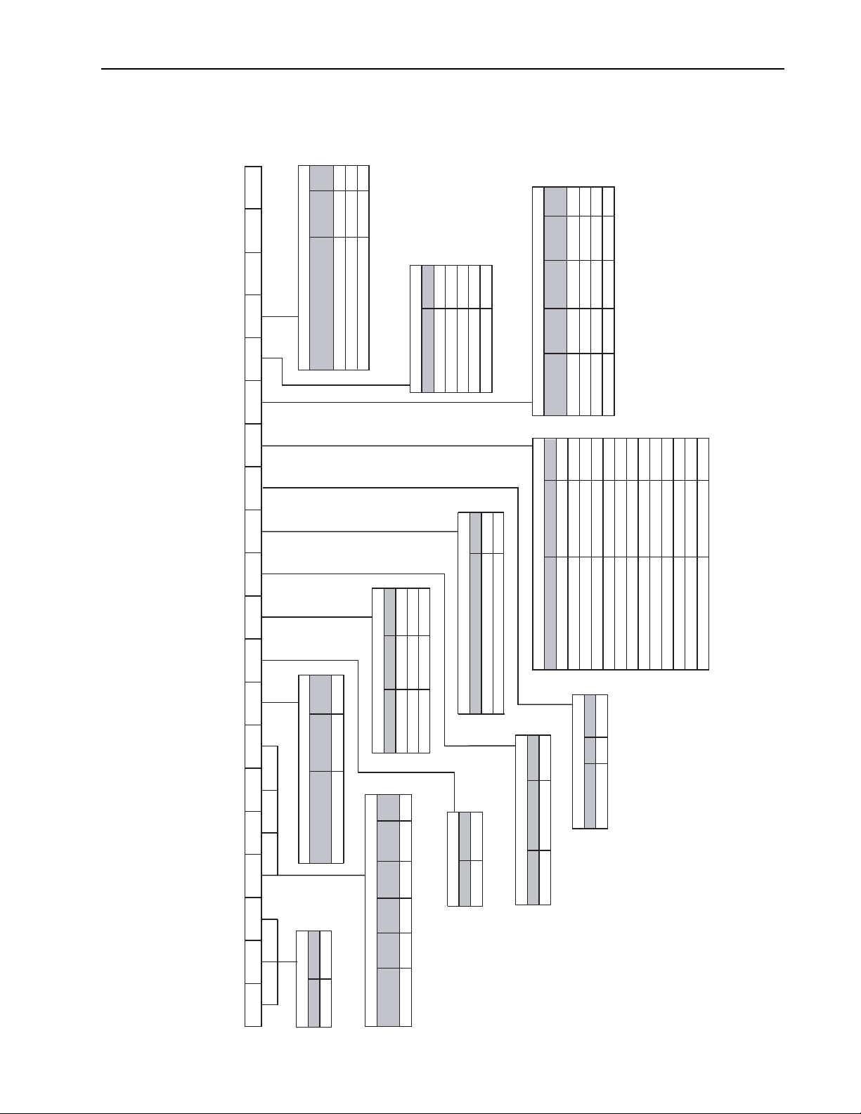
Catalog Number Explanation
1817 19 20
The LPM20 with High Performance Drive Control catalog numbering
scheme is shown below.
L
ENo
K
Cat.
Code
Comm.
No
Embedded
Options
CONTROL CONFIGURATIONS
Ethernet/IP
700S Phase II Control
700S Phase II Control w/DriveLogix™
700S Phase II Control w/DriveLogix™
1B 1
C 1E
A
Cat. CodeType
FEEDBACK OPTIONS
None N
Resolver
Stegmann Encoder
Multi-Device Interface
Cat.
1
2nd Encoder
Requires Expanded Cassette.
1
Logix
CONTROL OPTIONS
Control
Code
No A
SyncLink
No
Expansion
Cassette
Expanded
Option
700S Phase II
D
2D 2
B
C
YesNoYes
No
Yes
Yes
Expanded
Expanded
Expanded
700S Phase II
700S Phase II
700S Phase II
2
C
Q
Requires DriveLogix™5730 Controller.
42 43 44 45 46 4
1
E
E
N
Q
No
Yes
Yes
Ship CartonDocument(s) Cat. Code
Cat.
Code
DOCUMENTS & SHIPPING CARTON
English Doc Set
No Doc Set
HP
(Ref.)
Cat.
Code
Output
Current
Type
Source
No Doc Set
HIM
Coat
None
LPM20 with High Performance Drive Control
PRODUCT CATALOG NUMBER EXPLANATION
068
Conformal
Rating
Enclosure
Open Chassis / IP00 N
ENCLOSURE TYPE AND CONFORMAL COATING
A
N
Options Cat. Code
INPUT FILTER ITEMS
Replacement Power Module Only
Assembled Input Filter with Power Module
None N
Version Cat. Code
Note: HIM is ordered separately.
DPI Cat. Code
3
None N
DeviceNet
RIO R
ControlNet (Coax)
COMM SLOTS
DriveLogix (NetLinx)
None
N/A
N/A
N/A
NoNo N
EMC Cat. Code
INTERNAL EMC FILTERING
NoneNone N
Brake ResistorBrake IGBT Cat. Code
DYNAMIC BRAKE IGBT & BRAKE RESISTOR
Common Mode
N/A
ControlNet (Fiber)
N/A
N/A
RS485 DF-1 S
Ethernet
N/A
N/A
ControlNet (Coax)
ControlNet Redundant (Coax)
N/A
ControlNet (Fiber)
N/A
N/A
N/A
DeviceNet
ControlNet Redundant (Fiber)
EtherNet/IP (Twisted Pair)
Note that selections are mutually exclusive. For two Comm devices
Requires 700S Phase II Control with Logix Expansion.
(DPI and NetLinx), select the NetLinx Comm option and order the
DPI Comm kit separately.
3
4
12345678910111213141516
20ND NNE NNNNANE
PRODUCT
LPM20 20N
Product Cat. Code
Input
608 A 3 PH. 608 A D608 500
Current
INPUT VOLTAGE & OUTPUT CURRENT RATING
Input
380 - 480 VAC
Voltage Range
Page 12

P-6 Overview
Notes:
Page 13
Chapter 1
Installation/Wiring
This chapter provides information on mounting and wiring the LPM20 Drive.
For information on ... See page ...
Powe r R at in gs
Enclosure Ratings 1-2
Drive Component Locations 1-2
AC Supply Source Considerations 1-11
Mounting the Drive, Determining Wire Routing, and Grounding 1-12
Coolant Considerations 1-14
Installing Input Power Wiring 1-17
Installing Output Power Wiring 1-19
Powe r W ir ing 1-20
Using Input/Output Contactors 1-22
I/O Wiring 1-23
Main Control Board I/O and Encoder Settings 1-31
Connecting SynchLink 1-32
Active Converter Communication 1-33
Auto Tune Operation 1-33
Pre-charge Operation 1-34
Wiring the Active Converter Control Board I/O Terminals 1-34
CE Conformity 1-36
C-Tick Conformity 1-37
1-1
Power Ratings
Catalog Number
(positions 1-7 only)
20ND608 505 380 to 480 608 608 500 9000/3000
(1)
110% output current capability for one minute, 150% output current capability for 5 seconds.
(2)
Note that LPM20 drives are rated for use with water at specified temperatures and pressures as the coolant. Some coolant fluids may allow an increased
output rating while others may require the output to be derated. LPM20 drives are also capable of running at 2 kHz or 3 kHz.
Input
Power (KVA)
Most start-up difficulties are the result of incorrect wiring. Every precaution
must be taken to assure that the wiring is done as instructed. All items must
be read and understood before the actual installation begins.
ATTENTION: The following information is merely a guide for
proper installation. The Allen-Bradley Company cannot assume
!
responsibility for the compliance or the noncompliance to any
code, national, local or otherwise for the proper installation of this
drive or associated equipment. A hazard of personal injury and/or
equipment damage exists if codes are ignored during installation.
LPM20 Drives with High Performance Drive Control have power ratings as
described in Tabl e 1.A
Table 1.A Power Ratings
Input
Vol t a g e ( V )
Input
Current (Amps)
below:
(1)
Output Current
(2)
at 4 kHz
(Amps)
HP Ratings
Full Load Power Loss
Watts Fluid/Air
Page 14

1-2 Installation/Wiring
Enclosure Ratings
Drive Component Locations
LPM20 drives have the following enclosure rating:
• Open-Chassis Style: Intended to be installed in an enclosure.
LPM20 drives must be placed in an enclosure.
LPM20 Liquid-Cooled AC drives with High Performance Drive Control are
comprised of an input components section and a power module section.
Drive Input Component Locations
The input components section contains the following main components.
The numbered items listed below correspond to the numbers used in
Figure 1.1
1. Main Circuit Breaker
2. Circuit Breaker Operating Mechanism
3. Capacitor Bank Filter
4. Fan Tray
5. Precharge AC Contactors (3)
6. Fuses, 15A, Primary Control Transformer (2)
7. Control Transformer, 120 VAC, 1 Phase, 3 KVA
8. Ground Lug, 2-600 MCM
9. Inductor
10. Fuses, Precharge Resistors, 20A, 600V (3)
11. Terminal Block, 4-Position
12. Precharge Resistors (3)
13. 115V Fans (2)
. Replacement parts are listed in Chapter 3.
Page 15
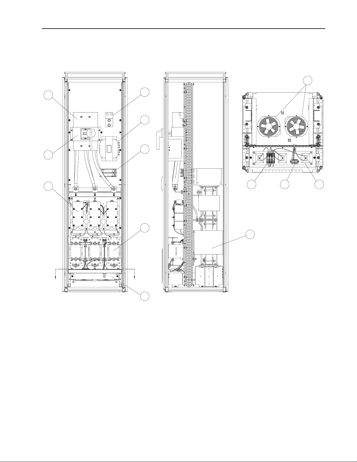
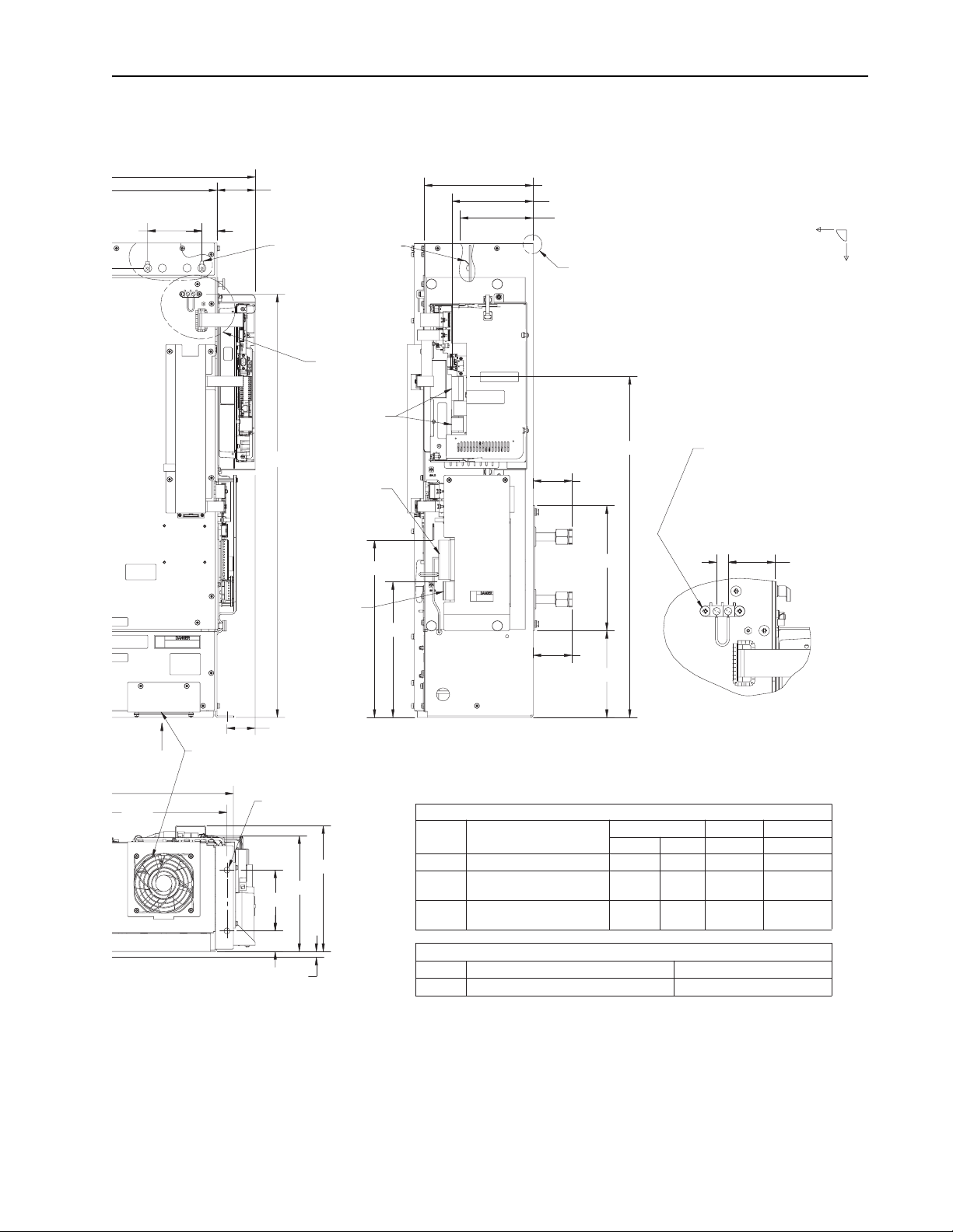
Figure 1.1 Drive Input Components
Installation/Wiring 1-3
13
1
2
3
8
7
6
10 11 12
SECTION A-A
5
9
A
A
4
See SECTION A-A
Page 16

1-4 Installation/Wiring
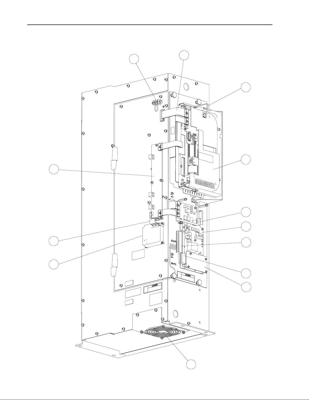
Power Module Component Locations
The power module section contains the following main components. The
numbered items listed below correspond to the numbers used in Figure 1.2
and Figure 1.3
1. Cable Assembly, 40-pin, 0.050 in. Pitch, Flex Film (1)
2. Cable Assembly, 30-pin, 0.050 in. Pitch, Flex Film (1)
3. Cable Assembly, 40-pin, 0.050 in. Pitch, Flex Film (1)
4. Wire Harness Assembly, Power Supply, Upper Gate (2)
5. Inverter Power Interface Assembly
6. Wire Harness Assembly, Power Supply, Lower Gate, PF700S (1)
7. 80 W Power Supply Assembly (2)
8. Insulation Sheet (2)
9. Cable Assembly, 40-pin, 0.050 in. Pitch, Flex Film (1)
10. Cable Assembly, 30-pin, 0.050 in. Pitch, Flex Film (1)
11. Wire Harness Assembly, Power Supply, Logic (2)
12. Wire Harness Assembly, Power Supply, Lower Gate (1)
13. Rectifier Power Interface Assembly
14. Current Feedback Device, 1000A (6)
15. Wire Harness Assembly, Gate Driver
16. Wire Harness Assembly, Current Feedback Device
17. Wire Harness Assembly, Input Filter (1)
18. Wire Harness Assembly, DC Bus Bleeder Resistors (1)
19. High Voltage Interconnect Assembly (1)
20. PF700S Voltage Feedback, 400V Class, Assembly (1)
21. Terminal Block, 2-Position (1)
22. Cable Assembly, 10-Position, Ribbon (1)
23. PF700S Control Cassette
24. Active Converter Assembly
25. Connector, Terminal Block, 15-pin
26. Connector, Terminal Block, 7-pin
27. Voltage Feedback Resistor, 460V, Assembly
28. Internal Fan
29. Communications Interface Assembly
30. Cable Assembly, 20-pin, 0.050 in. Pitch, Flex Film (optional)
31. Communications Module (optional)
. Replacement parts are listed in Chapter 3.
Page 17
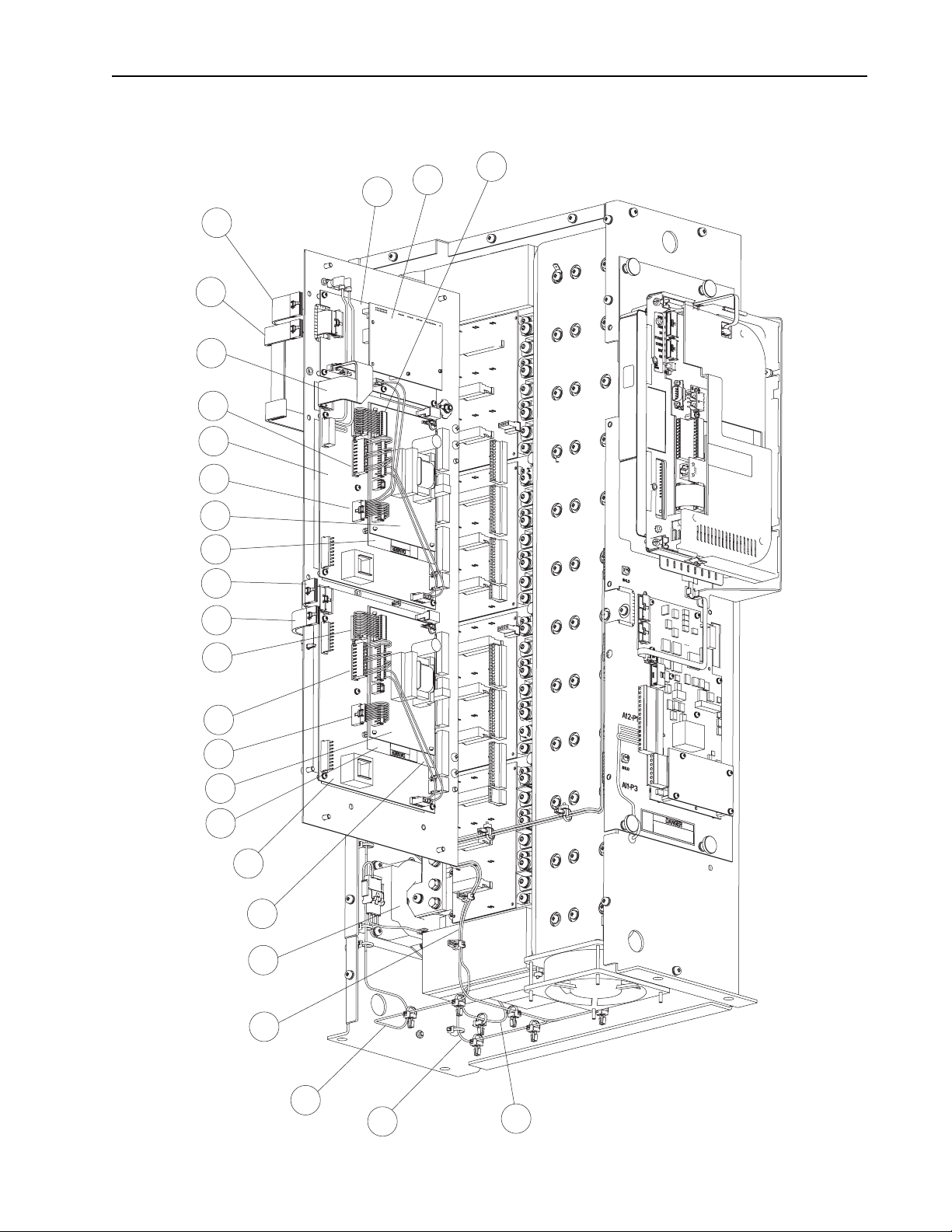
Figure 1.2 Power Module Component Locations – Door Open
Installation/Wiring 1-5
19
1
2
3
4
5
6
7
8
9
20
11
10
11
4
12
7
8
13
4
14
15
16
17
18
Page 18
1-6 Installation/Wiring
Figure 1.3 Power Module Component Locations – Door Closed
29
21
1
22
23
30
31
22
24
25
26
27
28
Page 19
Installation/Wiring 1-7
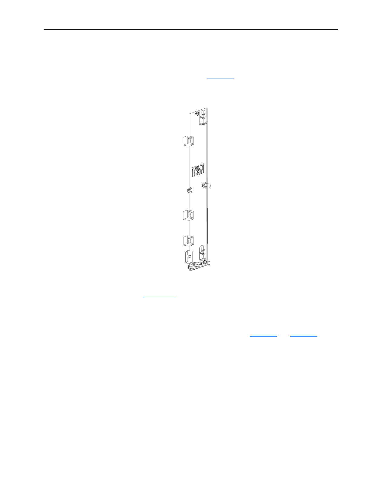
DPI Communication Port
The Communication Interface PCB contains an eight-position, female,
locking mini-DIN connector that is used as a DPI communication port. This
port (DPI Port 4 shown in Figure 1.4
between the LPM20 drive and another DPI device (for example, a HIM).
Figure 1.4 DPI Communication Interface Board
DPI
Port 3
below) provides communication
DPI
Port 4
DPI
Port 5
For more information regarding operating LPM20 drives with a HIM, refer
to Appendix
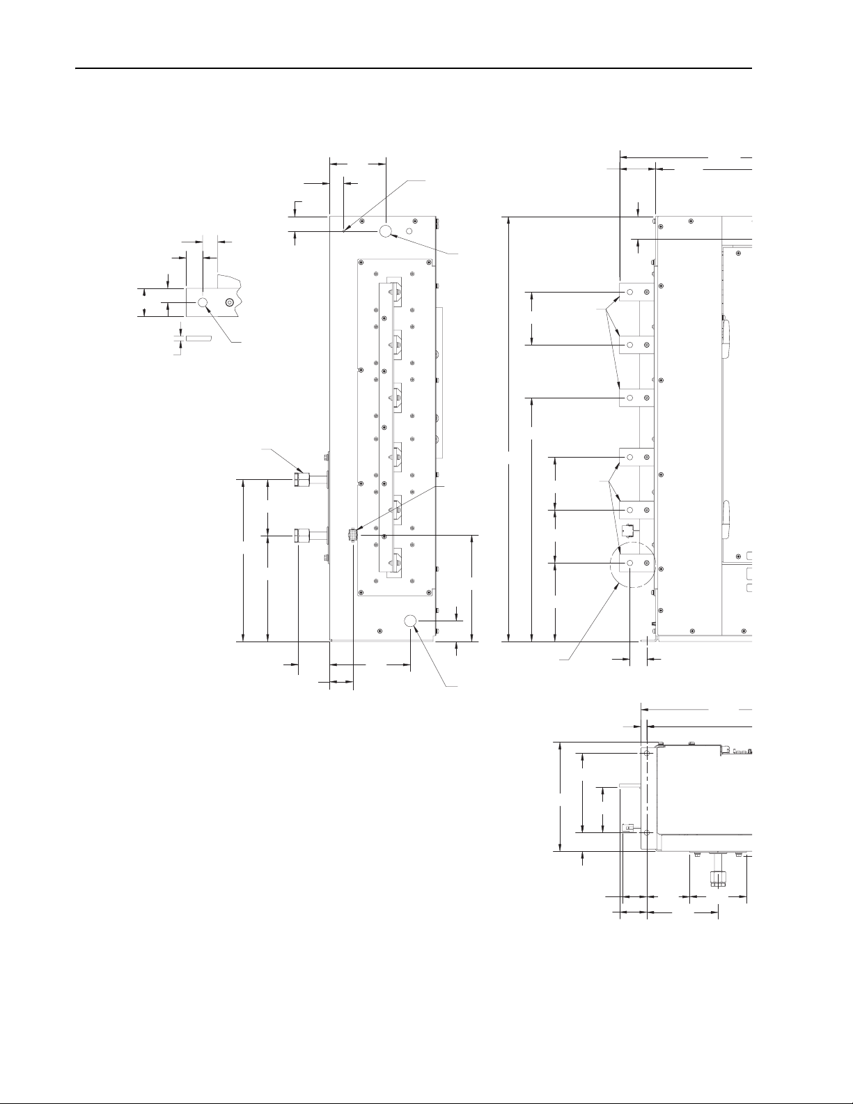
Determining Total Area Required Based on Drive Dimensions
Overall drive dimensions are illustrated in Figure 1.5 and Figure 1.6 as an
aid in calculating the total area required by the LPM20 drives.
B.
Page 20
1-8 Installation/Wiring
Figure 1.5 Power Module Dimensions and Mounting
1.19
0.80
0.88
0.75
1.50
0.25
Ø.472
DETAIL A
Input and Output Wiring Connection
SCALE 1:2
Coolant Connections
See Notes 2 and 3
OUT
4.76
13.72
IN
8.96
1.25
4.75
Ø.213 Thru
For M6 TAPTITE
Screw with Enclosure
Mounting Bracket
Lifting
Ø1.00
Both Sides
W
V
U
L3
A1-P1
L2
Input Filter
Harness
Connector
L1
9.03
36.04
4.48
20.66
Output
Wiring
to Motor
4.48
4.48
6.66
3.05
Drive
Drive
Input
Wiring
21.97
16.00
1.92
1.75
2.65 From Back of
Chassis to ORFS of
Sealing Surfaces
6.84
1.98
SEE DETAIL A
Lifting Ø1.00 Both Sides
LEFT SIDE VIEW
NOTES:
1. Floor Mounting Flange Holes:
A. Accept M8 Thread-Rolling Screws per SAE J1237.
B. Tightening Torque: 20-24 [N-M], 15-17 [FT-LBF].
2. Inlet and Outlet Coolant Connection Hardware Provided With Unit:
A. ORFS Braze Sleeve:
a. Material: Brass; for 5/8" O.D. Copper Tube.
b. Reference: Parker Hannifin P/N 10 TL-B, or equivalent.
B. ORFS Nut:
a. Material: Brass; for 5/8" O.D. Copper Tube, 1-14 UN/UNF-2B Thread.
b. Tightening Torque: 37-45 [N-M], 27.1-33.3 [FT-LBF].
c. Reference: Parker Hannifin P/N 10 BL-B, or equivalent.
3. Coolant Connection Hardware Provided by User:
A. ORFS Braze Adapter:
a. Material: Brass; for 5/8" O.D. Copper Tube, 1-14 UN/UNF-2A Thread.
b. Reference: Parker Hannifin P/N 10 LHB3-B, or equivalent.
B. ORFS O-Ring:
a. Material: Neoprene Rubber.
b. Size: 0.614 I.D., 0.070 Width.
c. Reference: Parker Hannifin P/N 2-016-C0873-70, or equivalent.
C. O-Ring Lubricant: Parker Hannifin Super-O-Lube, or equivalent.
9.25
6.75
1.56
2.08
1.43
0.50
3.88
2.31
FRONT
VIEW
3.64
6.05
18.49
4.81
Page 21
Installation/Wiring 1-9
Neg (-)
4.12
DC
A31
A32
A33
DC
Pos (+)
2.92
DC Bus Measurement
1.15
Points on Laminated
Bus Ass'y 0.25" x 0.032"
Male Faston. Accessible
by Removal of Top Cover.
SEE DETAIL
GATE KILL
A22-TB1 & TB2
Main Control Ass'y
Terminal Blocks
32.16
A12-P1 Active
Converter Control
Ass'y Terminal
Block 15-Pos.
A11-P2 Voltage
Feedback
Resistor Ass'y
Terminal
Block 7-Pos.
13.47
10.32
8.27 (A33)
6.17 (A22-TB1 & TB2)
5.54 (DC Bus Measurement Points)
SEE DETAIL COG
25.90
2.96
OUT
9.50
0.44
DETAIL COG
SCALE 5:16
CENTER OF GRAVITY:
X = 17.5"
Y = 3.1"
Z = 7.4" (into Plane
of Drawing)
WEIGHT:
162 LBS.
A33 Gate Kill
2-Pos. Terminal Block
With #6-32 Phillips/Slotted
Screws. Accepts #6 Stud Size
Spade Tongue Terminal.
Max. Width is 0.37".
IN
2 1
A33
2.96
6.60
Y
X
1.78
AIRFLOW
17.50
BOTTOM VIEW
2.15
Cooling Fan Requires 1.13" Minimum
Unobstructed Space Below Fan
Ø.453 (4)-PL. See Note 1
4.63
1.56
9.56
8.80
0.44
DETAIL GATE KILL
RIGHT SIDE VIEW
FIELD CONTROL WIRING
Name Reference
A33 #6-32 Screw 0.90 8 24 to 10
A12-P1
A11-P2
A22-TB1
A22-TB2
A1-P1
MATE
Screwdriver Blade:
0.032" Thk. x 0.125" Wide
Screwdriver Blade:
0.017" Thk. x 0.094" Wide
A1-P1 LINE SYNC. ASS'Y HARNESS CONNECTOR
Socket Housing, AMP P/N 172163-1 Socket, AMP P/N 770903-3
Pin Housing, AMP P/N 172171-1
Torque
[N-M] [IN-LBF] [AWG] [Inch]
0.79 7 26 to 12 0.31
0.22 1.9 28 to 16 0.25
SCALE 5:8
Wire Size Strip Length
Pin, AMP P/N 770904-3
−
Page 22
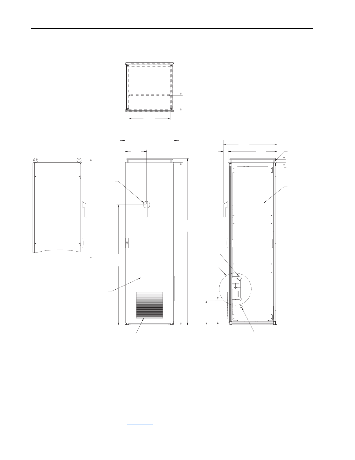
1-10 Installation/Wiring
C/B
Disconnect
Handle
Figure 1.6 Drive Input Dimensions
6.076
Area for Input Power Wiring
[154,3]
20.157
[512]
Area for Input Power Wiring
23.80
Left Panel/Divider Panel
[605]
10.49
[266]
2.38
[60]
26.20
[665]
23.82
[605]
Field Install
Roof Spacers
Rittal p/n
DK7967.000
Exhaust Air
Space Required
Divider Panel
Rittal p/n
TS8609.060
Left View Shown
with Lifting Eye-Bolts
as Shipped
Rittal TS8 Enclosure
600mm x 600mm x 2000mm
81.11
[2060]
80.89
[2055]
78.99
[2006]
58.48
[1485]
Intake Louver
323mm x 323mm
Edge Guard
Power Cable
Opening Input
to Power Module
10.13
[257]
12.24
Ref
[311]
Control Cable
Opening Input
to Power Module
Verifying that Site Provides for Recommended Air Flow Clearances
Be sure there is adequate clearance for air circulation around the
user-supplied enclosure. A 6-inch minimum clearance is required wherever
vents are located in the cabinet.
For proper cabinet ventilation, roof spacers must be field installed as shown
in Figure 1.6
.
Page 23

Installation/Wiring 1-11
Verifying Power Module Input Ratings Match Supplied Power
It is important to verify that plant power will meet the input power
requirements of the LPM20 drive’s Power Module circuitry. See Ta ble 1 . A
for input power rating specifications. Be sure input power to the drive
corresponds to the drive nameplate voltage and frequency.
AC Supply Source Considerations
LPM20 drives are suitable for use on a circuit capable of delivering up to a
maximum of 100,000 rms symmetrical amperes, and a maximum of 480 volts.
A circuit breaker with shunt trip as supplied with input drive components with
the appropriate kAIC rating must always be used upstream of the power module.
ATTENTION: To guard against personal injury and/or equipment
damage caused by improper circuit breaker selection, use only the
!
recommended circuit breakers specified in Tab le 1 . B
Unbalanced or Ungrounded Distribution Systems
LPM20 drives should not be used with a supply system that is ungrounded and
when the phase-to-phase voltage exceeds 125% of normal line-to-line voltage.
ATTENTION: LPM20 drives contain protective MOVs on the
drive’s printed circuit boards. The MOVs are referenced to ground.
!
The MOVs should not be disconnected.
Input Power Conditioning
Certain events on the power system supplying a drive can cause component
damage or shortened product life. They are:
.
• The power system has power factor correction capacitors switched in and
out of the system, either by the user or by the power company.
• The power source has intermittent voltage spikes in excess of 6000 volts.
These spikes could be caused by other equipment on the line or by events
such as lightning strikes.
• The power source has frequent interruptions.
Wiring Requirements for the Drive
Certain drive requirements should be checked before continuing with the
drive installation. Wire sizes, branch circuit protection, encoder feedback (for
FVC regulation), and wiring to disable the drive are all areas that need to be
evaluated.
Operation of the drive can be disabled in two locations. Gate Kill terminal
block (A33) on the front of the power structure can be used to disable the
firing of inverter IGBTs. When the connection between terminals 1 and 2 is
opened, inverter IGBTs are disabled independent of any software control.
This action also generates fault 207 in the inverter to enunciate this
Page 24
1-12 Installation/Wiring
condition. As a result of this fault, the active converter is also turned off, but
this is done via software operation. The firing of IGBTs in the active
converter can be disabled independently of any software control by opening
the connection between terminals 13 and 14 on the active converter control
assembly terminal block A12-P1. This action also genrates a fault in the
inverter to enunciate this condition. Wiring diagrams are shown in
Figure 1.5
Input Line Branch Circuit Protection
!
Table 1.B AC Input Circuit Breaker Values
and on page C-3.
ATTENTION: Most codes require that upstream branch
circuit protection be provided to protect input power wiring.
The circuit breaker values provided in the Drive Input
Components are listed in Tabl e 1.B
.
Mounting the Drive, Determining Wire Routing, and Grounding
LPM20 Drive Catalog Number
(positions 1-7 only)
20ND608 380-480 VAC 800 A
Note: One 120 VAC shunt trip to be installed as shown in the drive wiring
diagram on page C-2
This section shows how to mount the drive and properly ground it. Also
described is the wiring to be routed in and out of the drive.
Lifting and Mounting the Power Module
Use the following procedure to lift the LPM20 power module and mount it
in the required enclosure:
1. Install two s-hooks into the power module to serve as lifting points. Two
1-inch through holes are provided in the sheet metal chassis.
2. Connect 18 inches (nominal) of chain between the s-hooks and secure
them with a clevis clamp.
3. Using an overhead or portable hoist (minimum 1/2-ton rated capacity),
attach a free-fall chain to the chain secured to the drive. Take up any
vertical slack in the chain.
Input Voltage
.
Circuit Breaker
Provided
4. Using the hoist, lift the power module from the horizontal shipping pallet.
5. Position the power module in the enclosure.
6. In order to maintain a flat mounting surface and to ensure that bolt tightness
is maintained, use flat washers and split-ring lock washers under the bolt
heads. Refer to Figure 1.5
7. Remove the s-hooks and chain.
for power module mounting dimensions.
Page 25

Installation/Wiring 1-13
Verifying the Drive’s Watts Loss Rating
When mounting the drive inside of an enclosure, you should determine the
watts loss rating of the drive from Tabl e 1.A
load power loss watts value at 2 kHz (rated carrier frequency). Ensure that
the enclosure is adequately ventilated with 0
the drive’s watts loss rating.
Determining Input, Motor Output, Ground, and Control Wire Routing for the Drive
All wiring should be installed in conformance with the applicable local,
national, and international codes (e.g., NEC/CEC). Signal wiring, control
wiring, and power wiring must be routed in separate conduits to prevent
interference with drive operation. Use grommets, when hubs are not
provided, to guard against wire chafing. Figure 1.5
wire routing, grounding terminal, and power terminal strips of LPM20
drives with High Performance Drive Control.
. This table lists the typical full
° to 40° C ambient air based on
and Figure 1.6 show the
ATTENTION: Do not route signal and control wiring with
!
Do not route more than three sets of motor leads through a single conduit.
This will minimize cross-talk that could reduce the effectiveness of noise
reduction methods. If more than three drive/motor connections per conduit
are required, shielded cable must be used. If possible, each conduit should
contain only one set of motor leads.
!
Grounding the Drive
power wiring in the same conduit. This can cause interference
with drive operation. Failure to observe this precaution could
result in damage to, or destruction of, the equipment.
ATTENTION: Unused wires in conduit must be grounded at
both ends to avoid a possible shock hazard caused by induced
voltages. Also, if a drive sharing a conduit is being serviced or
installed, all drives using this conduit should be disabled to
eliminate the possible shock hazard from cross-coupled motor
leads. Failure to observe these precautions could result in bodily
injury.
ATTENTION: The user is responsible for conforming with
!
Use the following steps to ground the drive:
1. Open the door of the enclosure.
all applicable local, national, and international codes. Failure to
observe this precaution could result in damage to, or
destruction of, the equipment.
Page 26

1-14 Installation/Wiring
2. Run a suitable equipment grounding conductor unbroken from the drive
to the motor’s ground terminal and then to earth ground. Use one of the
bolts that pass through the drive baseplate and are used to fasten the drive
to the wall or cabinet. See Figure 1.6
connections to the proper torque as shown in Table 1 . D
3. Connect a suitable grounding conductor to the motor frame and the
remote control station (if used). Run each conductor unbroken to earth
ground. When adding more than one grounding conductor wire to a
single chassis ground, twist the conductors together. Tighten these
grounding connections to the proper torque as shown in Table 1.D
4. Close the door of the enclosure.
. Tighten these grounding
.
.
Coolant Considerations
LPM20 drives use o-ring face seal fittings for connection to the coolant
supply. The coolant is typically clean water with a corrosion inhibitor as
described in this section.
LPM20 drive coolant connections are made with o-ring face seal fittings.
The copper tube running from the heatsink to the o-ring fittings is covered
with closed cell foam insulation.
The mating connection is shown in Figure 1.7
the following steps:
1. Coat the o-ring with the o-ring lubricant. The goal is a thin film covering
the entire o-ring surface. Avoid excess globs of lubricant.
2. Insert the o-ring into the o-ring groove in the external thread-side fitting
on the user side. Avoid any twisting of the o-ring.
3. Assemble the fittings and tighten to a torque of 37 to 45 N-m (or 27 to 33
lb.-ft.). Use a backup wrench on the user side fitting to avoid twisting the
drive side tubing.
Figure 1.7 Mating Connection
DRIVE SIDE CONNECTION
ORFS Braze Sleeve
5/8-inch O.D.
Copper Tube
(Parker p/n 10-TL-B)
. The mating process includes
USER SIDE CONNECTION
ORFS Braze Adapter
(Parker p/n 10-LOHB3-B)
ORFS Nut
(Parker p/n 10-BL-B)
O-Ring, Neoprene
(Parker p/n 2-016-CO873-70)
(Parker p/n 884-2GRAMS-LUBE)
O-Ring Lubricant
5/8-inch O.D.
Copper Tube
Backup Wrench
(Use to prevent twisting
during nut tightening.)
Page 27

Installation/Wiring 1-15
Other recommendations include:
1. The allowable coolant temperature range is 0°C to 40°C (32°F to 105°F).
When using coolant at a temperature below the dew point of the
surrounding air, condensation could accumulate on the drive heatsink
and/or circuit boards and damage the drive. In this situation, install a
coolant flow regulating device and tube/hose insulation. A flow
regulating device modulates the coolant flow rate to a level that permits
the drive heatsink temperature to rise above the dew point. Insulation for
customer side tube or hose may be closed-cell foam insulation with
minimum 1/2-inch wall thickness.
2. Install a flow switch after the coolant outlet connection to shutoff the
drive if coolant flow drops below 4 gpm.
3. Circulate water through the drive only when the drive is also powered.
Failure to do this may result in condensation accumulating on the drive
heatsink and/or circuit boards, which could damage the drive.
4. For applications requiring a closed loop coolant system, ensure the
system is vented to remove air that would otherwise degrade the
performance of the drive heatsink.
Coolant Connections
LPM20 drives with High Performance Drive Control have inlet and outlet
connections as shown in Figure 1.5
are bolted to the heatsink.
The rated working pressure of the drive is 185 psig. Coolant supply and
return lines should be sized for 10 gpm/185 psig service with a maximum
operating temperature of 40°C (105°F). The required operating flow rate
and pressure drop is specified in Tabl e 1.C
Coolant Requirements
LPM20 drives are rated for use with coolant consisting of clean water with a
corrosion inhibitor. Deionized water is prohibited. Use distilled water or
water with the following concentrations:
• Less than 50 ppm of sulfate and chloride.
• Less than 50 ppm of hard water ions such as Mg++ and Ca++.
Coolant must be properly strained and/or filtered to ensure it is free of
contamination.
. Tube assemblies with O-ring fittings
.
The coolant must be compatible with the following materials: Copper,
brass, aluminum, and neoprene.
Page 28

1-16 Installation/Wiring
Table 1.C Coolant Requirements for LPM20 Drives
LPM20 Drive
Catalog Number
(positions 1-7 only)
20ND608
(1)
Water equals good quality or distilled water with Chemtool, Inc. corrosion inhibitor, 2% inhibitor by volume.
(2)
WEG25 equals good quality or distilled water with approved ethylene glycol, 25% glycol by volume.
(3)
WEG50 equals good quality or distilled water with approved ethylene glycol, 50% glycol by volume.
Max. Output
Current (Amps)
608 5 to 40 7 10 Water
608 0 to 40 7 10 WEG25
550 0 to 40 7 10 WEG50
608 0 to 40 10 22 WEG50
608 0 to 30 7 10 WEG50
Corrosion Inhibitor
A corrosion inhibitor is required. The following two options are approved
sources:
1. Chemtool, Inc. (www.chemtool.com) part number Watertool 4435-C.
The recommended concentration of the inhibitor is 8 to 10% by volume.
2. Dow Chemical (www.dow.com) Dowtherm
glycol. The recommended concentration of the inhibitor is 25% by
volume.
Coolant
Temperature
Range (°C)
Minimum
Coolant Flowrate
(GPM)
Pressure Drop From Drive
Inlet to Drive Outlet (PSIG) at
Minimum Coolant Flow Rate
®
SR-1 inhibited ethylene
Coolant
Typ e
(1)
(2)
(3)
(3)
(3)
Dowtherm is a registered trademark of the Dow Chemical Company.
ATTENTION: Ethylene glycol must be inhibited and silicate
!
Biocide
A biocide may be needed to control biological growth. Use of a biocide is
permitted. For specific recommendations, consult a reputable water
treatment company.
free. Use of common silicate-containing, automotive-type
ethylene glycol solutions is prohibited as they may damage the
drive and cooling module equipment.
Page 29

Installation/Wiring 1-17
Installing Input Power Wiring
Circuit Breaker
Line Side Lugs
This section describes incoming line components and how to install them.
Installing Transformers and Reactors (Not Recommended)
The LPM20 AC drive may be used on distribution systems with 100,000
amps or less symmetrical fault current capacity. The Drive Input
components consists of a 3% line reactor and a harmonic line filter.
Additional input inductance is not recommended.
Figure 1.8 Drive Input Wiring
Ground Lug
2-600 MCM
Torque Label for
Line Side Lugs
L1 L2 L3
NOTE: Proper torque for Line Side Lugs is labeled on the circuit breaker.
Page 30

1-18 Installation/Wiring
Installing a Required External/Separate Input Disconnect
An input disconnect must be installed in the line before the drive input
terminals in accordance with local, national, and international codes (e.g.,
NEC/CEC). The disconnect should be sized according to the in-rush current
as well as any additional loads the disconnect might supply. The trip rating
for the inrush current (10-12 times full load current) should be coordinated
with that of the input isolation transformer, if used. Refer to Installing
Transformers and Reactors (Not Recommended) on page 1-17 for
additional information.
Installing Power Wiring from the Input Filter Section to the Power Module
Use the following steps to connect AC input power to the drive:
ATTENTION: Do not route signal and control wiring with
!
power wiring in the same conduit. This can cause interference
with drive operation. Failure to observe this precaution could
result in damage to, or destruction of, the equipment.
1. Connect the three-phase AC input power leads (three-wire 380-480
VAC) to the appropriate terminals.
2. Tighten the AC input power terminals to the proper torque as shown in
Table 1.D
Table 1.D Terminal Tightening Torques
Terminals Hardware Type
L1 to L6 M10, CI. 9.8 43 N-m (31 lb.-ft.)
U, V, W M10, CI. 9.8 43 N-m (31 lb.-ft.)
GND, PE M8, CI. 9.8 22 N-m (16 lb.-ft.)
.
Maximum Tightening Torque
(+
10%)
Page 31

Installation/Wiring 1-19
Installing Output Power Wiring
This section provides instructions on wiring output contactors, motor
overload protection, and output wiring to the motor.
Installing Mechanical Motor Overload Protection (Optional)
To provide the motor with overload protection, local, national, and
international codes (e.g., NEC/CEC) may require one of the following:
• a motor thermostat be installed internal to the motor.
• a mechanical thermal motor overload relay, sized to protect the motor, be
installed between the motor and the drive’s output terminals.
In multiple motor applications (V/Hz regulation only), each motor must
have its own user-supplied overload and branch circuit protection.
Installing Output Wiring from the Drive Output Terminals to the Motor
Important: The total motor lead length must not exceed 76 meters (250 feet).
Use the following steps to connect the AC output power wiring from the
drive to the motor:
1. Wire the three-phase AC output power motor leads by routing them as
shown in Figure 1.5
.
Do not route more than three sets of motor leads through a single
conduit. This will minimize cross-talk that could reduce the effectiveness
of noise reduction methods. If more than three drive/motor connections
per conduit are required, shielded cable must be used. If possible, each
conduit should contain only one set of motor leads.
ATTENTION: Do not route signal and control wiring with
!
!
2. Connect the three-phase AC power motor leads to the appropriate output
terminals. Figure 1.5
3. Tighten the three-phase AC output power terminals to the proper torque
as shown in Tab le 1. D
power wiring in the same conduit. This can cause interference
with drive operation. Failure to observe these precautions could
result in damage to, or destruction of, the equipment
ATTENTION: Unused wires in conduit must be grounded at
both ends to avoid a possible shock hazard caused by induced
voltages. Also, if a drive sharing a conduit is being serviced or
installed, all drives using this conduit should be disabled to
eliminate the possible shock hazard from cross-coupled motor
leads. Failure to observe these precautions could result in
bodily injury.
shows the locations of the output power terminals.
.
Page 32

1-20 Installation/Wiring
Power Wiring
ATTENTION: National Codes and standards (NEC, VDE, BSI
etc.) and local codes outline provisions for safely installing
!
electrical equipment. Installation must comply with specifications
regarding wire types, conductor sizes, branch circuit protection,
and disconnect devices. Failure to do so may result in personal
injury and/or equipment damage.
Cable Types Acceptable for 200-600 Volt Installations
A variety of cable types are acceptable for drive installations. For many
installations, unshielded cable is adequate, provided it can be separated
from sensitive circuits. As an approximate guide, allow a spacing of 0.3
meters (1 foot) for every 10 meters (32.8 feet) of length. In all cases, long
parallel runs must be avoided. Do not use cable with an insulation thickness
less than or equal to 15 mils (0.4mm/0.015 in.). Use Copper wire only. Wire
gauge requirements and recommendations are based on 75°C. Do not
reduce wire gauge when using higher temperature wire.
Unshielded
THHN, THWN or similar wire is acceptable for drive installation in dry
environments provided adequate free air space and/or conduit fill rates
limits are provided. Do not use THHN or similarly coated wire in wet
areas. Any wire chosen must have a minimum insulation thickness of 15
mils and should not have large variations in insulation concentricity.
ATTENTION: To avoid a possible shock hazard caused by
induced voltages, unused wires in the conduit must be grounded at
!
both ends. For the same reason, if a drive sharing a conduit is being
serviced or installed, all drives using this conduit should be
disabled. This will help minimize the possible shock hazard from
“cross coupled” motor leads.
Shielded/Armored Cable
Shielded cable contains all of the general benefits of multi-conductor cable
with the added benefit of a copper braided shield that can contain much of
the noise generated by a typical AC Drive. Strong consideration for shielded
cable should be given in installations with sensitive equipment such as
weigh scales, capacitive proximity switches and other devices that may be
affected by electrical noise in the distribution system. Applications with
large numbers of drives in a similar location, imposed EMC regulations or a
high degree of communications/networking are also good candidates for
shielded cable.
Shielded cable may also help reduce shaft voltage and induced bearing
currents for some applications. In addition, the increased impedance of
shielded cable may help extend the distance the motor can be located from
the drive without the addition of motor protective devices such as terminator
Page 33

Installation/Wiring 1-21
networks. Refer to Reflected Wave in Wiring and Grounding Guidelines for
PWM AC Drives, publication DRIVES-IN001.
Consideration should be given to all of the general specifications dictated by
the environment of the installation, including temperature, flexibility,
moisture characteristics and chemical resistance. In addition, a braided
shield should be included and specified by the cable manufacturer as having
coverage of at least 75%. An additional foil shield can be greatly improve
noise containment.
A good example of recommended cable is Belden® 295xx (xx determines
gauge). This cable has 4 XLPE insulated conductors with a 100% coverage
foil and an 85% coverage copper braided shield (with drain wire)
surrounded by a PVC jacket.
Table 1.E Recommended Shielded Wire
Location Rating/Type Description
Standard
(Option 1)
Standard
(Option 2)
Class I & II;
Division I & II
600V, 90°C (194°F)
XHHW2/RHW-2 Anixter
B209500-B209507,
Belden 29501-29507, or
equivalent
Tray rated 600V, 90°C
(194°F) RHH/RHW-2
Anixter OLF-7xxxxx or
equivalent
Tray rated 600V, 90°C
(194°F) RHH/RHW-2
Anixter 7V-7xxxx-3G or
equivalent
• Four tinned copper conductors with XLPE insulation.
• Copper braid/aluminum foil combination shield and
tinned copper drain wire.
• PVC jacket.
• Three tinned copper conductors with XLPE insulation.
• 5 mil single helical copper tape (25% overlap min.) with
three bare copper grounds in contact with shield.
• PVC jacket.
• Three bare copper conductors with XLPE insulation
and impervious corrugated continuously welded
aluminum armor.
• Black sunlight resistant PVC jacket overall.
• Three copper grounds on #10 AWG and smaller.
Other types of shielded cable are available, but the selection of these types
may limit the allowable cable length. Particularly, some of the newer cables
twist 4 conductors of THHN wire and wrap them tightly with a foil shield.
This construction can greatly increase the cable charging current required
and reduce the overall drive performance. These cables are not
recommended.
Page 34

1-22 Installation/Wiring
Using Input/Output Contactors
Input Contactor Precautions
ATTENTION: A contactor or other device that routinely
disconnects and reapplies the AC line to the drive to start and stop
!
the motor can cause drive hardware damage. The drive is designed
to use control input signals that will start and stop the motor. If an
input device is used, operation must not exceed one cycle per
minute or drive damage will occur.
ATTENTION: The drive start/stop/enable control circuitry
includes solid state components. If hazards due to accidental
!
contact with moving machinery or unintentional flow of liquid, gas
or solids exist, an additional hardwired stop circuit may be required
to remove the AC line to the drive. An auxiliary braking method
may be required.
Output Contactor Precaution
ATTENTION: To guard against drive damage when using output
contactors, the following information must be read and understood.
!
One or more output contactors may be installed between the drive
and motor(s) for the purpose of disconnecting or isolating certain
motors/loads. If a contactor is opened while the drive is operating,
power will be removed from the respective motor, but the drive will
continue to produce voltage at the output terminals. In addition,
reconnecting a motor to an active drive (by closing the contactor)
could produce excessive current that may cause the drive to fault. If
any of these conditions are determined to be undesirable or unsafe,
an auxiliary contact on the output contactor should be wired to a
drive digital input that is programmed as “Enable.” This will cause
the drive to execute a coast-to-stop (cease output) whenever an
output contactor is opened.
Page 35

Installation/Wiring 1-23
I/O Wiring
Important points to remember about I/O wiring:
• Use Copper wire only. Wire gauge requirements and recommendations
are based on 75°C. Do not reduce wire gauge when using higher
temperature wire.
• Wire with an insulation rating of 600V or greater is recommended.
• Control and signal wires should be separated from power wires by at
least 0.3 meters (1 foot).
• 4100CCF3 Flex I/O cable for use with DriveLogix is 0.9 meters (3 ft.)
maximum length.
Important: I/O terminals labeled “(–)” or “Common” are
earth ground and are designed to greatly reduce common mode
interference. Grounding these terminals can cause signal noise.
ATTENTION: Configuring an analog input for 0-20mA
operation and driving it from a voltage source could cause
!
component damage. Verify proper configuration prior to applying
input signals.
ATTENTION: Hazard of personal injury or equipment damage
exists when using bipolar input sources. Noise and drift in
!
sensitive input circuits can cause unpredictable changes in motor
speed and direction. Use speed command parameters to help
reduce input source sensitivity.
not referenced to
Signal and Control Wire Types
Table 1.F Recommended Signal Wire
Signal Type/
Where Used Wire Type(s) Description
Standard Analog I/O Belden 8760/9460 (or equiv.) 0.750 mm
pair, 100% shield with drain
Remote Pot Belden 8770 (or equivalent) 0.750 mm
Encoder/Pulse I/O
Less 30.5 m (100 ft.)
Encoder/Pulse I/O
30.5 m to 152.4 m
(100 ft. - 500 ft.)
Encoder/Pulse I/O
152.4 m to 259.1 m
(500 ft. - 850 ft.)
(1)
Belden 9730 is 3 individually shielded pairs (2 channel plus power). If 3 channel is required, use Belden 9728 (or equivalent).
(2)
Belden 8790 is 1 shielded pair.
(3)
Belden 9892 is 3 individually shielded pairs (3 channel), 0.33 mm2 (22 AWG) plus 1 shielded pair 0.5 mm2 (20 AWG) for power.
(4)
Belden 9773 is 3 individually shielded pairs (2 channel plus power). If 3 channel is required, use Belden 9774 (or equivalent).
(5)
If the wires are short and contained within a cabinet which has no sensitive circuits, the use of shielded wire may not be
necessary, but is always recommended.
Combined: Belden 9730 (or
equivalent)
Signal: Belden 9730/9728
(or equivalent)
Power: Belden 8790
Combined: Belden 9892
Signal: Belden 9730/9728
(or equivalent)
Power: Belden 8790
Combined: Belden 9773/9774
(or equivalent)
(1)
shielded
0.196 mm2(24AWG),
individually shielded
0.196 mm2(24AWG),
(1)
individually shielded
(2)
0.750 mm2(18AWG)
(3)
0.330 mm2 or 0.500 mm2
0.196 mm2(24AWG),
(1)
individually shielded
(2)
0.750 mm2(18AWG)
0.750 mm2(18AWG),
(4)
individually shielded pair
2
(18AWG), twisted
2
(18AWG), 3 cond.,
Minimum
Insulation Rating
(5)
300V,
75-90°C
(167-194°F)
(3)
Page 36

1-24 Installation/Wiring
Table 1.G Recommended Control Wire for Digital I/O
Typ e Wire Type (s ) Desc rip ti on
Unshielded Per US NEC or applicable national
or local code
Shielded Multi-conductor shielded cable
such as Belden 8770 (or equivalent)
Wiring the Main Control Board I/O Terminals
Terminal blocks TB1 and TB2 contain connection points for all inputs,
outputs, and standard encoder connections. Both terminal blocks reside on
the Main Control Board of the PF700S Control Cassette.
Remove the terminal block plug from the socket, and make connections.
Important: For NEMA 1 applications, all wiring must be routed through
the conduit plate on the drive. Route any wires from the
expanded cassette to the base cassette and out of the drive.
Reinstall the plug when wiring is complete. The terminal blocks have keys,
which make it difficult to insert a terminal plug into the wrong socket.
Figure 1.9 Main Control Board I/O Terminal Locations
— 300V,
0.750 mm
3 conductor, shielded.
2
(18AWG),
Insulation
Rating
60°C
(140°F)
minimum
TB1 Terminals
TB2 Terminals
Page 37

Installation/Wiring 1-25
I/O Terminal Blocks
Table 1.H Main Control Board I/O Terminal Block Specifications
Name Description
I/O Blocks Signal and encoder
power connections
(1)
Maximum/minimum that the terminal block will accept - these are not recommendations.
Table 1.I TB1 Terminals
Wire Size Range
Maximum Minimum Maximum Recommended
2
1.5 mm
(16 AWG)
(1)
0.14 mm
(28 AWG)
2
0.25 N-m
(2.2 lb.-in.)
Torque
0.22 N-m
(1.9 lb.-in.)
Terminal Signal Description
1 Analog Input 1 Common Bipolar, differential input, +/-10V, 0-20 mA, 13 bit + sign
1
2
3
4
5
6
7
8
9
10
11
12
13
14
15
16
17
18
19
20
21
22
23
24
2 Analog Input 1 (+/-) 800
3 Shield Analog Input Shield
4 Analog Input 2 Common Bipolar, differential input, +/-10V, 0-20 mA, 13 bit + sign
5 Analog Input 2 (+/-) 806
6 Analog Input 3 [NTC-] Common Differential input, 0-10V, 10 bit (for motor control mode FVC2,
7 Analog Input 3 [NTC+] 812
8 Shield Analog Output Shield
9 Analog Output 1 (-) Bipolar, differential input, +/-10V, 0-20 mA, 11 bit + sign
10 Analog Output 1 (+)
11 Analog Output 2 (-) 839, 840
12 Analog Output 2 (+)
13 +10V Reference Rating: 20 mA maximum load (recommend 5K ohm
14 Reference Common
15 -10V Reference
16 Encoder A Normal current draw per channel: 20 mA 230-233
17 Encoder A (Not)
18 Encoder B
19 Encoder B (Not)
20 Encoder Z
21 Encoder Z (Not)
22 Encoder Reference (+) 12 or 5 V dc power supply for primary encoder interface
23 Encoder Reference (-)
24 Encoder Shield Connection point for encoder shield
20K ohm impedance at Volt; 500 ohm impedance at mA
20K ohm impedance at Volt; 500 ohm impedance at mA
this is the temperature adaptation input).
2K ohm minimum load
potentiometer)
Rating: 300 mA maximum
Related
Parameter
832, 833
Page 38

1-26 Installation/Wiring
Figure 1.10 TB1 Terminals — Analog Wiring Examples
Input/Output Connection Example
0-10V Analog Input 0-10V Analog Input - Internal Source Required Parameter Changes
1
2
3
4
5
6
7
8
9
10
11
12
0-10V Analog Input - Bipolar
1
2
3
4
5
6
7
8
9
10
11
12
13
14
15
16
17
18
19
20
21
22
23
24
13
14
15
16
17
18
19
20
21
22
23
24
0-10V Analog Input - External Source
1
2
3
4
5
6
7
8
9
10
11
12
-Signal or Source Common
+Signal
Shield / Common
-Signal or Source Common
+Signal
Shield / Common
-Signal or Source Common
+Signal
Shield / Common
Page 39

Figure 1.10 TB1 Terminals — Analog Wiring Examples (Continued)
-
+
-
+
Input/Output Connection Example
Installation/Wiring 1-27
Analog Output
+/- 10V dc
Used to drive analog meters
displaying speed and current.
Primary Encoder Interface -
Supports 5V dc/12 V dc
differential encoders with
internal power supply.
0-10V Analog Output Required Parameter Changes
1
2
3
4
5
6
7
8
9
10
11
12
Using Analog Output 1 (-10V to +10V) to meter
Motor RPM and direction:
• Send the data to the Analog Output Parameter
833 [Anlg Out1 Real], the destination, linked to
Parameter 71 [Filtered SpdFdbk], the source.
• Scale the Output to the source parameter.
Example: Parameter 835 [Anlg Out1 Scale] =
175 (where Parameter 4 [Motor NP RPM] 1750
is divided by 10V output).
Using Analog Output 2 (-10V to +10V) to meter
Motor current:
• Send the data to the Analog Output Parameter
840 [Anlg Out2 Real], the destination, linked to
Parameter 308 [Output Current], the source.
• Scale the Output to the source parameter.
Example: Parameter 822 [Anlg Out2 Scale] = xx
(where Parameter 2 [Motor NP FLA] is divided
by 10V output).
Primary Encoder - Internal Supply Using Encoder 0 as speed feedback:
13
14
15
16
17
18
19
20
21
22
23
24
Encoder
A
A-
B
B-
The Z channel is not
Z
required in typical
Z-
applications
+
-
• Set Parameter 222 [Motor Fdbk Sel Pri] to a
value of 0 (Encoder 0 = default), so the drive will
use this encoder as the primary motor speed
feedback device.
• Set the value of Parameter 232 [Encoder 0
PPR] to match the installed encoder’s resolution
(Pulses per Revolution).
Primary Encoder - External Supply
13
14
15
16
17
18
19
20
21
22
23
24
Power +V
Common -V
Shield
Encoder
A
A-
B
B-
The Z channel is not
Z
required in typical
Z-
applications
+
-
Page 40

1-28 Installation/Wiring
Table 1.J TB2 Terminals
Terminal Signal Description
1 24V dc Common (-) Drive supplied 24V dc logic input power
1
2
3
4
5
6
7
8
9
10
11
12
13
14
15
16
2 24V dc Source (+)
3 Digital Output 1 24V dc Open Collector (sinking logic)
4 Digital Output 1/2 Common Common for Digital Outputs 1 and 2
5 Digital Output 2 24V dc Open Collector (sinking logic)
6 Relay Output 3 (NC) Relay contact output
7 Relay Output 3 Common
8 Relay Output 3 (NO)
9 Digital Input 1-3 Common Common for Digital Inputs 1, 2, and 3
10 Digital Input 1 High speed 12-24V dc sourcing Digital Input
11 Digital Input 2 826
12 Digital Input 3 Load: 15 mA at 24V dc sourcing 827
13 Digital Input 4-6 Common Common for Digital Inputs 4, 5, and 6
14 Digital Input 4 Load: 10 mA at 24V dc sinking/sourcing
15 Digital Input 5 829
16 Digital Input 6 (HW Enable) 830
Rating: 300 mA maximum load
Rating: Internal Source = 150 mA maximum
External Source = 750 mA
Rating: Internal Source = 150 mA maximum
External Source = 750 mA
Rating: 115V ac or 24V dc = 2 A maximum Inductive/Resistive
Load: 15 mA at 24V dc
Load: 7.5 mA at 115V ac
Related
Parameter
816, 847
851, 852
856, 857
825
828
Page 41

Figure 1.11 TB2 Terminals — Digital Wiring Examples
Input/Output Connection Example
Installation/Wiring 1-29
Digital Inputs used for enable
and precharge control.
Note:
24V dc Supply - supports
only on-board digital inputs.
Do not use for circuits outside
the drive.
Note:
The factory default for all
Digital Inputs is 24V. This must
be switched in order to use
115V.
Note:
Digital Inputs 1, 2, and 3 are
always 24V dc.
Sourcing Digital Inputs - using internal power supply Sourcing and Sinking Definitions
Com
1
24V DC
2
3
4
5
6
7
8
Sourcing Digital Outputs - using internal power supply
Com
1
24V dc
2
3
4
5
6
7
8
Sinking Digital Inputs - using internal power supply
Com
1
24V dc
2
3
4
5
6
7
8
9
10
11
12
13
14
15
16
9
10
11
12
13
14
15
16
The digital inputs and digital outputs of the LPM20
with High Performance Drive Control support
Sourcing or Sinking configuration. Typically, digital
inputs are sourcing devices and digital outputs are
sinking devices. The following definitions apply
throughout this section:
Sourcing a Digital Input
A. Connect the digital input common (return) directly
to the power supply common.
B. Applying positive voltage to the digital input will
cause it to activate (pull up).
Sourcing a Digital Output
A. Connect the digital output common (return)
directly to the power supply common.
B. Connect the device to be controlled by the digital
output to the positive voltage, and the device
common to the digital output.
Sinking a Digital Input
A. Connect the digital input common to the power
supply positive voltage.
B. Applying 0V or common to the digital input will
cause it to activate (pull down).
Sinking a Digital Output
A. Connect the digital output common (return) to the
power supply positive voltage.
B. Connect the digital output to the device to be
controlled, and the device common to the power
supply common.
Note:
Digital Inputs 1, 2, and 3 can only be configured as
sourcing inputs. Digital Inputs 4, 5, and 6 can be
configured as sourcing or sinking inputs.
Sinking Digital Outputs - using internal power supply
Com
1
24V dc
2
3
4
5
6
7
8
Page 42

1-30 Installation/Wiring
Figure 1.11 TB2 Terminals — Digital Wiring Examples (Continued)
Input/Output Connection Example
Digital Inputs - 24V dc Sourcing Digital Inputs - using internal power supply, 2-Wire
Control
Com
1
24V DC
2
3
4
5
6
7
8
Sourcing Digital Inputs - using internal power supply, 3-Wire
Control
Com
1
24V DC
2
3
4
5
6
7
8
10
11
12
13
14
15
16
10
11
12
13
14
15
16
9
RUN
Enable
9
START
STOP
Enable
Required Parameter Changes
• Set Parameter 829 [DigIn 5 Sel] to a value of 7
(Run).
• Parameter 153 [Control Options] bit 8
(3WireControl) will automatically be OFF for 2-wire
control.
• Set Parameter 168 [Normal Stop Mode] for the
desired stopping mode:
0 = Ramp Stop
1 = CurLim Stop
2 = Coast Stop
• Set Parameter 829 [DigIn 5 Sel] to a value of 14
(Normal Stop).
• Set Parameter 828 [DigIn 4 Sel] to a value of 5
(Start).
• Parameter 153 [Control Options] bit 8
(3WireControl) will automatically be ON for 3-wire
control.
• Set Parameter 168 [Normal Stop Mode] for the
desired stopping mode:
0 = Ramp Stop
1 = CurLim Stop
2 = Coast Stop
Hard Enable Circuitry
A dedicated hardware enable input is provided on TB2 - Terminal 16
(Digital Input 6) for applications that require the drive to be disabled
without software interpretation.
Page 43

Main Control Board I/O and Encoder Settings
SWITCH S5
SIDE VIEW
Up = Open = Off
FRONT
TOP VIEW
S1
Installation/Wiring 1-31
JUMPER P22
34
= HW Enable
12
34
= No HW Enable
12
Down = Closed = On
SWITCH S2
Up = Open = Off
Down = Closed = On
SIDE VIEW
SWITCH S3
Up = Open = Off
Down = Closed = On
Table 1.K Switch Settings
12
FRONT
TOP VIEW
12
34
SIDE VIEW
FRONT
TOP VIEW
12
SWITCH S4
Up = Open = Off
Down = Closed = On
SIDE VIEW
FRONT
TOP VIEW
12
Function Switch Open Closed Default Notes
Configuring Digital Input 6 for
Hardware Enable (HW Enbl)
Analog Input 1 S5-1 Voltage Current Voltage Change with Power Off.
Analog Input 2 S5-2 Voltage Current Voltage Change with Power Off.
Digital Inputs 4-6 Voltage S4-1, S4-2 115V ac 24V dc 24V dc Change with Power Off.
Digital Input 1 Voltage S3-1 24V dc 12V dc 24V dc Change with Power Off.
Digital Input 2 Voltage S3-2 24V dc 12V dc 24V dc Change with Power Off.
Encoder Voltage Supply S2-1 12V dc 5V dc 24V dc Change with Power Off.
Encoder Signal A Voltage S2-2 12V dc 5V dc 12V dc
Encoder Signal B Voltage S2-3 12V dc 5V dc 12V dc
Encoder Signal Z Voltage S2-4 12V dc 5V dc 12V dc
Function Switch Open Closed Default Notes
DriveLogix Processor S1 RUN Remote Program Processor mode.
P22
Jumper
pin 2-4
HW enable
pin 1-3
No enable
pin 2-4
HW enable
No jumper = HW enable
Set all switches the same.
Please note there are two separate values for an encoder.
Page 44

1-32 Installation/Wiring
Connecting SynchLink
SynchLink provides high-speed synchronization and communication
between multiple LPM20 drives with High Performance Drive Control (or
other products with SynchLink capability).
Class 1 LED Product
ATTENTION: Hazard of permanent eye damage exists when
!
When planning and connecting the SynchLink network, please refer to the
SynchLink System Design Guide (Publication No. 1756-TD008).
Connect cables to J1 (transmit) and J2 (receive) connectors on the left side
of the Main Control Board. Push the plug into the socket until it produces an
audible click.
using optical transmission equipment. This product emits intense
light and invisible radiation. Do not look into module ports or
fiber optic cable connectors.
J2 (Receive)
J1 (Transmit)
Important: Do not overtighten tie-wraps.
Table 1.L SynchLink Cables and Accessories
Description Cat. No.
2 x 1 M Fiber Optic Link 1403-CF001
2 x 3 M Fiber Optic Link 1403-CF003
2 x 5 M Fiber Optic Link 1403-CF005
10 M Fiber Optic Link 1403-CF010
20 M Fiber Optic Link 1403-CF020
50 M Fiber Optic Link 1403-CF050
100 M Fiber Optic Link 1403-CF100
250 M Fiber Optic Link 1403-CF250
500 M Fiber Optic Bulk 1403-CFBLK
Page 45

Installation/Wiring 1-33
Table 1.L SynchLink Cables and Accessories (Continued)
Description Cat. No.
SynchLink Fiber-Hub, 1 input, Base 1751-SLBA
SynchLink Fiber-Hub, 4 output, “Star” Splitter 1751-SL4SP
SynchLink Bypass Switch 1751-SLBP/A
Table 1.M Fiber Optic Cable Assembly
Specification
Connecting Cables 200/230 micron HCS (Hard Clad Silica)
• Ve r s a link V- S y s tem
• Lucent Technologies,
• Specialty Fibers Technology Division
Maximum Cable Length 300 meters with no more than one splice or one adapter
Minimum Cable Length 1 meter
Minimum inside bend radius 25.4mm (1 in.) Any bends with a shorter inside radius can
permanently damage the fiber optic cable. Signal attention
increases with decreased inside bend radius.
Operating Wavelength 650 nm (Red)
Data Rate 5 Mbps
Maximum Node Count • 10 - Daisy Chain
• 256 - Star Configuration
Active Converter Communication
Auto Tune Operation
The active converter communicates control and starts information with the
700S controller over DPI Data Link D.
• 700AC Parameter 71 - [Converter Status] is transferred to 700S
Parameter 657 - [DPI Data In D1]. This may be used to monitor the
operation of the active converter.
• 700S Parameter 666 - [DPI Data Out D1] is transferred to 700AC
Parameter 70 - [Converter Control]. This may be used to start and stop
the converter.
• 700S Parameter 667 - [DPI Data Out D2] is transferred to 700AC
Parameter 72 - [Converter Min Vdc]. This may be used to set the
minimum DC link voltage reference.
For more information, please refer to the PowerFlex 700 Active Converter
Power Module User Manual (Publication No. PFLEX-UM002…).
The pre-charge bypass contactor must be closed and the converter must be
enabled before Auto Tuning of the inverter can be performed. See the
section below on Pre-charge Operation to accomplish this.
700S Parameter 431 sets the current level for the Auto Tune procedure. The
default value of 50.0% is high for large horsepower drives. A typical value
for a motor connected to an LPM20 drive is 20.0%.
After the converter is ready and parameters are set correctly, the Auto Tune
operation can be initiated from the HIM as described in the PowerFlex 700S
High Performance AC Drive — Phase II Control User Manual (Publication
No. 20D-UM006…).
Page 46

1-34 Installation/Wiring
Pre-charge Operation
The pre-charge bypass contactor is controlled by the active converter. On
power up, the contactor is open so the pre-charge resistors limit the current
charging the DC link. The contactor may operate in one of three ways as
selected by 700AC-Parameter 50 - [Start Config]:
• If “Run On Start” is selected, then logic must be added to the application
to turn on 700AC-Parameter 70 - [Converter Control] bit 0 to close the
pre-charge and enable the converter to regulate the DC Link Voltage. The
inverter may not be started until 700AC-Parameter 71 - [Converter
Status] bits 2 and 3 have been turned on by the active converter.
• If “Run On PwrUp” is selected, then the pre-charge bypass contactor is
automatically closed several seconds after power is turned on and the
converter is automatically enabled.
• If “Manual Cntrl” is selected, then the pre-charge bypass contactor is
manually controlled by 700AC-Parameter 52 - [Manual Control] bit 0,
and enabling of the active converter is manually controlled by
700AC-Parameter 52 bit 1. This mode is primarily intended for
troubleshooting or during startup.
WARNING: The user must verify that the pre-charge is closed
!
before enabling the inverter or the pre-charge resistors may be
damaged. This can be done with a Logix application program or by
wiring the auxiliary contacts on the pre-charge bypass contactor in
series with the run permissive on the inverter.
Wiring the Active Converter Control Board I/O Terminals
Terminal blocks A11-P2 and A12-P1 contain connection points for all
inputs, outputs, and power connections to the Active Converter Control
Board.
Remove the terminal block plug from the socket, and make connections. For
more information, please refer to the PowerFlex 700 Active Converter
Power Module User Manual (Publication No. PFLEX-UM002…).
Reinstall the plug after wiring is complete. The terminal blocks have keys,
which make it difficult to insert a terminal plug into the wrong socket.
Page 47

Figure 1.12 Active Converter Control Board I/O Terminal Locations
A12 - Active Converter
Control Assembly
A12 - P1
Terminals
1
2
3
4
5
6
7
8
9
10
11
12
13
14
15
7
6
5
4
3
2
1
SW1
Installation/Wiring 1-35
SW1
DPI Slave = OFF (Default)
ON
DPI Master = ON
ON
A11 - P2
Terminals
A11 - Voltage Feedback
Resistor Assembly
I/O Terminal Blocks
Table 1.N Active Converter Control Board I/O Terminal Block Specifications
Name Description
I/O Blocks Signal and power
connections
(1)
Maximum/minimum that the terminal block will accept - these are not recommendations.
Table 1.O Active Converter Control Board A12-P1 Terminal Descriptions
Pin Description Pin Description
1 Comm Out + 9 Aux Out N.O.
2 Comm Out - 10 Aux Out Common
3 SOC Out + 11 Analog In Signal
4 SOC Out - 12 Analog In Common
5 Comm In + 13 Safety HW Enable
6 Comm In - 14 24 Vdc
7 SOC In + 15 Aux Input
8 SOC In -
Wire Size Range
Maximum Minimum Maximum Recommended
2
1.5 mm
(16 AWG)
(1)
0.14 mm
(28 AWG)
2
0.25 N-m
(2.2 lb.-in.)
Torque
0.22 N-m
(1.9 lb.-in.)
Page 48

1-36 Installation/Wiring
Table 1.P Active Converter Voltage Feedback Board A11-P2 Terminal Descriptions
Pin Description
1L1
4L2
7L3
CE Conformity
EMC Instructions
CE Compliance
Compliance with the Low Voltage Directive 73/23/EEC and
Electromagnetic Compatibility Directive 89/336/EEC has been
demonstrated using harmonized European Norm (EN) standards published
in the Official Journal of the European Communities. LPM20 drives comply
with the EN standards listed below when installed according to instructions
in this section.
Low Voltage Directive (73/23/EEC)
• EN50178 Electronic equipment for use in power installations
EMC Directive (89/336/EEC)
• EN61800-3 Adjustable speed electrical power drive systems - Part 3:
EMC requirements and specific test methods
CE Declarations of Conformity are available online at:
http://www.ab.com/certification/ce/docs
General Notes
• Without additional external filtering, LPM20 drives satisfy the 2nd
Environment high-frequency emission limits of EN61800-3. Without
external mitigation, LPM20 drives are not intended to be used on a
low-voltage public network which supplies residential or office
premises; radio frequency interference is expected if used in such an
environment.
• The drive motor cable should be kept as short as possible in order to
minimize electromagnetic emission and capacitive currents.
• Use of line filters in ungrounded systems is not recommended.
• Conformity of the drive with CE EMC requirements does not guarantee
an entire machine or installation complies with CE EMC requirements.
Many factors influence overall machine/installation compliance.
Page 49

Installation/Wiring 1-37
Essential Requirements for CE Compliance
Conditions 1-5 listed below must be satisfied for LPM20 drives to meet the
requirements of EN61800-3:
1. Standard LPM20 CE compliant drive.
C-Tick Conformity
2. Grounding as described in Grounding the Drive
3. Output power wiring to the motor, and all control/signal wiring must use
braided shielded cable with a shield coverage of 75% or greater, or metal
conduit.
4. The shields of all shielded cables must be terminated with the proper
connectors to chassis/earth.
5. Motor cables must not exceed 20 meters (65.6 feet) in length.
Compliance of LPM20 drives with the Australian Radiocommunications
Act of 1992 has been demonstrated through compliance with EN61800-3.
Both the General Notes and the Essential Requirements for CE Compliance
provided above apply to C-Tick compliance for LPM20 drives.
C-Tick Declarations of Compliance are available online at:
http://www.ab.com/certification/c-tick/index.html
on page 1-13.
Page 50

1-38 Installation/Wiring
Notes:
Page 51

Chapter 2
Start Up
This chapter describes how to start up the LPM20. Refer to Appendix B for
a brief description of the LCD HIM (Human Interface Module).
For information on ... See page ...
Prepare For Drive Start-Up
Status Indicators 2-3
Assisted Start Up 2-4
ATTENTION: Power must be applied to the drive to perform the
following start-up procedure. Some of the voltages present are at
!
incoming line potential. To avoid electric shock hazard or damage
to equipment, only qualified service personnel should perform the
following procedure. Thoroughly read and understand the
procedure before beginning. If an event does not occur while
performing this procedure, Do Not Proceed. Remove Power
including user-supplied control voltages. User-supplied voltages
may exist even when main AC power is not applied to the drive.
Correct the malfunction before continuing.
2-1
Prepare For Drive Start-Up
Before Applying Power to the Drive
Important: If you have a DriveLogix application, you must first connect
the battery before starting this procedure.
❏ 1. Confirm that motor wires are connected to the correct terminals and are
secure.
❏ 2. Confirm that encoder wires are connected to the correct terminals and
are secure.
❏ 3. Confirm that all inputs are connected to the correct terminals and are
secure.
❏ 4. Verify that AC line power at the disconnect device is within the rated
value of the drive.
❏ 5. Verify that control power voltage is correct.
The remainder of this procedure requires that a HIM be installed. If an
operator interface is not available, remote devices should be used to start
up the drive.
Page 52

2-2 Start Up
Applying Power to the Drive
❏ 6. Apply AC power and control voltages to the drive.
If any digital input is configured to “Stop – CF” (CF = Clear Fault) or
“Enable,” verify that signals are present or the drive will not start. For a
list of potential digital input conflicts or if a fault code appears, please
refer to the PowerFlex 700S High Performance AC Drive — Phase II
…
Control User Manual (Publication No. 20D-UM006
❏ 7. Examine the Inverter Status and Rectifier Status LEDs located on the
DPI Communications Interface Board on the front of the power module
(see Figure 2.1
refer to the descriptions in Figure 3.1
shown in Tab le 2.A
Table 2.A Common Causes of a Pre-Start Alarm
Examine Par 156 - [Run Inhibit Status]
bit Description Action
1 No power is present at the Enable Terminal (TB2 -Terminal 16). Apply the enable.
2, 3, 4 A stop command is being issued. Close all stop inputs.
5 Power loss event is in progress, indicating a loss of the AC input voltage. Restore AC power.
6 Data supplied by the power structure EEprom is invalid or corrupt. Cycle power. If problem persists, replace the power structure.
7 Flash update in progress. Complete Flash procedures.
8 Drive is expecting a Start Edge and is receiving a continuous signal. Open all start buttons and remove all start commands.
9 Drive is expecting a Jog Edge and is receiving a continuous signal. Open all jog buttons and remove all jog commands.
10 A conflict exists between the Encoder PPR programming (Par 232 or 242)
and the encoder configuration for edge counts (Par 233 or 243, bits 4 and 5).
11 The drive cannot precharge because a precharge input is programmed and
no signal is present.
Start input configured but stop not configured. Program Par 838-840 to include a stop button; rewire the drive.
Run input configured but control options do not match. Program Par 153, Bit 8 to “0” (2 wire control).
Start input configured but control options do not match. Program Par 153, Bit 8 to “1” (3 wire control).
12
14 Invalid Feedback Device for Permanent Magnet Motor Control Set Par 222 to a value of “5” (FB Opt Port0)
Multiple inputs configured as Start or Run. Reprogram Par 838-840 so multiple starts, multiple runs or any
Multiple inputs configured as Jog1. Program Par 838-840 so only (1) is set to Jog1.
Multiple inputs configured as Jog 2. Program Par 838-840 so only (1) is set to Jog2.
Digital Configuration
Multiple inputs configured as Fwd/Rev. Program Par 838-840 so only (1) is set to Fwd/Rev.
). Verify that they are flashing green. If not in this state,
. Also, check the possible causes
and take necessary corrective action.
Verify encoder data and reprogram.
Reprogram the input or close the precharge control contact.
combination do not exist.
), Chapter 4.
❏ 8. Proceed to Start-Up routine.
Page 53

Start Up 2-3
Status Indicators
Figure 2.1 Drive Inverter and Rectifier Status LEDs
DPI Communications
Interface Board
(front surface of
power module)
Inverter Status LED
Rectifier Status LED
Page 54

2-4 Start Up
Figure 2.2 Drive RUN LED on PF700S Control Cassette
Drive RUN LED
RUN
I/O
DriveLogix Indicators
(only supplied when
drive is equipped with
DriveLogix
Controller)
Name Color State Description
Drive RUN LED
(topmost indicator)
DriveLogix
Indicators
If the DriveLogix option is not present, the associated indicators will not be
present.
Important Information
5730
FORCE
COM
BAT
OK
Green Off Drive inverter is not providing a modulated output.
Steady Drive inverter is providing a modulated output.
For status descriptions of the six DriveLogix indicators, please refer to the
DriveLogix
5730 Controller User Manual (Publication No. 20D-UM003…).
Assisted Start Up
Power must be applied to the drive when viewing or changing parameters.
Previous programming may affect the drive status and operation when
power is applied.
For Assisted Start-Up information, please refer to the PowerFlex 700S High
Performance AC Drive — Phase II Control User Manual (Publication No.
20D-UM006
…
) in Chapter 2.
Page 55

Chapter 3
Troubleshooting
Chapter 3 provides information to guide you in troubleshooting the LPM20
with High Performance Drive Control.
For information on ... See page ...
Faults and Alarms
Drive Status 3-2
Manually Clearing Drive Faults 3-3
Drive Fault Descriptions 3-3
Active Converter Fault Descriptions 3-3
Clearing Drive Alarms 3-3
Common Symptoms and Corrective Actions 3-4
Test Equipment Needed To Troubleshoot 3-6
Verifying That DC Bus Capacitors Are Discharged 3-6
Replacement Parts 3-7
3-1
Faults and Alarms
A fault is a condition that stops the drive. There are two fault types.
Type Fault Description
Non-Resettable This type of fault normally requires drive or motor repair. The cause of
➀
User Configurable These faults can be enabled/disabled to annunciate or ignore a fault
➁
An alarm is a condition that, if left untreated, may stop the drive. There are
two alarm types.
Type Alarm Description
User Configurable These alarms can be enabled or disabled through [Alarm Config 1]
➀
Non-Configurable These alarms are always enabled.
➁
the fault must be corrected before the fault can be cleared. The fault will
be reset on power up after repair.
condition.
parameter.
Page 56

3-2 Troubleshooting
Drive Status
Power Module LED Indications
The Inverter Status LED and Rectifier Status LED are located on the DPI
Communications Interface Board on the front of the power module. The
LEDs indicate the status of the inverter and the rectifier as shown in the
table in Figure 3.1
receiving power.
Figure 3.1 Inverter and Rectifier Status LEDs and Indications
DPI Communications
Interface Board
(front surface of
power module)
. Note that if the LEDs are off, it indicates the drive is not
Inverter Status LED
Rectifier Status LED
Color State Description
Green Flashing Drive ready, but not running and no faults are present.
Steady Drive running, no faults are present.
Yellow Flashing A type 2 (non-configurable) alarm condition exists, but drive continues to run.
Steady A type 1 (user configurable) alarm condition exists, but drive continues to run.
Red Flashing A fault has occurred.
Steady A non-resettable fault has occurred.
Page 57

Troubleshooting 3-3
HIM Indication
The LCD HIM also provides visual notification of a fault or alarm condition.
Condition Display
Drive is indicating a fault.
The LCD HIM immediately reports the fault condition by displaying
the following:
• “Faulted” appears in the status line
• Fault number
• Fault name
• Time that has passed since fault occurred
Press Esc to regain HIM control.
Drive is indicating an alarm.
The LCD HIM immediately reports the alarm condition by displaying
the following:
• Alarm name (Type 2 alarms only)
• Alarm bell graphic
F-> Faulted Auto
Hz
0.0
— Fault — F 5
Main Menu:
OverVoltage
Diagnostics
Time Since Fault
0000:23:52
Parameter
F-> Power Loss Auto
Hz
0.0
Main Menu:
Diagnostics
Parameter
Device Select
Manually Clearing Drive Faults
Drive Fault Descriptions
Active Converter Fault Descriptions
Step Key(s)
1. Press Esc to acknowledge the fault. The fault information will be
removed so that you can use the HIM.
2. Address the condition that caused the fault.
The cause must be corrected before the fault can be cleared.
3. After corrective action has been taken, clear the fault by one
these methods:
• Press Stop
• Cycle drive power
• Set parameter 240 [Fault Clear] to “1.”
• “Clear Faults” on the HIM Diagnostic menu.
For a complete list and description of drive faults (with possible corrective
actions, when applicable) and alarms, please refer to the PowerFlex 700S
High Performance AC Drive — Phase II Control User Manual (Publication
No. 20D-UM006…) in Chapter 4.
For a complete list and description of active converter faults (with possible
corrective actions, when applicable) and alarms, please refer to the
PowerFlex 700 Active Converter Power Module User Manual (Publication
No. 20D-UM006…) in Chapter 4.
Esc
of
Clearing Drive Alarms
Drive alarms are automatically cleared when the condition that caused the
alarm is no longer present.
Page 58

3-4 Troubleshooting
Common Symptoms and Corrective Actions
Drive does not Start from Start or Run Inputs wired to the terminal block.
Cause(s) Indication Corrective Action
Drive is faulted. Flashing red
status light.
Incorrect input wiring. See
Figure 1.11
Incorrect digital input programming.
• Mutually exclusive choices have
• Exclusive functions (i.e, direction
• Stop is factory default and is not
Drive does not Start from HIM.
Cause(s) Indication Corrective Action
Drive is programmed for 2 wire
control. HIM Start button is disabled
for 2 wire control.
Active fault. Flashing or
Enable input is open. Flashing yellow
for wiring examples.
been made (i.e., Jog and Jog
Forward).
control) may have multiple inputs
configured.
wired or is open.
None Wire inputs correctly and/or install jumper.
None Program [Digital Inx Sel] parameter for correct
Flashing yellow
status light and
“DigIn CflctB”
indication on
LCD HIM.
[Drive Status 2]
shows type 2
alarm(s).
None If 2 wire control is required, no action needed.
steady red LED.
LED.
Clear the fault:
• Press HIM Stop key if HIM is control
source.
• Cycle power.
• Set [Fault Clear] parameter to 1.
• “Clear Faults” on the HIM Diagnostic
menu.
inputs.
Start or Run programming may be missing.
Program [Digital Inx Sel] parameter to resolve
conflicts.
Remove multiple selections for the same
function.
Install stop button to apply a signal at stop
terminal.
If 3 wire control is required, program [Digital
Inx Sel] parameter for correct inputs.
Reset fault.
Close terminal block enable input.
Drive does not respond to changes in Speed Command.
Cause(s) Indication Corrective Action
No value is coming from the source
of the command.
Incorrect reference source has been
programmed.
Incorrect reference source is being
selected via remote device or digital
inputs.
LCD HIM
Status Line
indicates “At
Speed” and
output is 0 Hz.
None 3. Check [Speed Ref Source] parameter for
None 5. Check [Drive Status 1] parameter, bits 12
1. If the source is an analog input, check
wiring and use a meter to check for
presence of signal.
2. Check [Commanded Freq] parameter for
correct source.
the source of the speed reference.
4. Reprogram [Speed Ref A Sel] parameter
for correct source.
and 13 for unexpected source selections.
6. Check [Dig In Status] parameter to see if
inputs are selecting an alternate source.
7. Reprogram digital inputs to correct “Speed
Sel x” option.
Page 59

Troubleshooting 3-5
Motor and/or drive will not accelerate to Commanded Speed.
Cause(s) Indication Corrective Action
Acceleration time is excessive. None Reprogram [Accel Time x] parameter.
Excess load or short acceleration
times force the drive into current
limit, slowing or stopping
acceleration.
Speed command source or value is
not as expected.
Programming is preventing the drive
output from exceeding limiting
values.
Motor operation is unstable.
Cause(s) Indication Corrective Action
Motor data was incorrectly entered. None Correctly enter motor nameplate data.
Drive will not reverse motor direction.
Cause(s) Indication Corrective Action
Digital input is not selected for
reversing control.
Digital input is incorrectly wired. None Check input wiring. (See page 1-25)
Direction mode parameter is
incorrectly programmed.
Motor wiring is improperly phased
for reverse.
A bipolar analog speed command
input is incorrectly wired or signal is
absent.
None 1. Check [Drive Status 2] parameter, bit 10 to
see if the drive is in Current Limit.
2. Remove excess load or reprogram [Accel
Time x] parameter.
None Check for the proper Speed Command using
Steps 1 through 7 previously described.
None Check [Maximum Speed] parameter and
[Maximum Freq] parameter to assure that
speed is not limited by programming.
None Check [Digital Inx Sel] parameter. Choose
correct input and program for reversing mode.
None Reprogram [Direction Mode] parameter for
analog “Bipolar” or digital “Unipolar” control.
None Switch two motor leads.
None 1. Use meter to check that an analog input
voltage is present.
2. Check wiring. (See page 1-25)
Positive voltage commands forward direction.
Negative voltage commands reverse direction.
Page 60

3-6 Troubleshooting
Test Equipment Needed To Troubleshoot
Verifying That DC Bus Capacitors Are Discharged
An isolated multimeter will be needed to measure the DC bus voltage and to
make resistance checks. Note that dedicated troubleshooting test points are
not provided.
ATTENTION: DC bus capacitors retain hazardous voltages
!
The LPM20 drive’s DC bus capacitors retain hazardous voltages after input
power has been disconnected. Perform the following steps before touching
any internal components:
1. Turn off and lock out input power. Wait five minutes.
2. Verify that there is no voltage at the power module’s input power
terminals (L1, L2, and L3) as shown in Figure 1.8
after input power has been disconnected. After disconnecting
input power, wait five (5) minutes for the DC bus capacitors to
discharge and then check the voltage with a voltmeter to ensure
the DC bus capacitors are discharged before touching any
internal components. Failure to observe this precaution could
result in severe bodily injury or loss of life.
.
3. Measure the DC bus potential with a voltmeter while standing on a
non-conductive surface and wearing insulated gloves (1000 V). The DC
bus measurement points are located on the Inverter (see Figure 3.2
4. After the drive has been serviced, reapply input power.
Figure 3.2 Location of DC Bus Voltage Measurement Points
DC
Neg (-)
DC
Pos (+)
DC Bus Measurement
Points on Laminated
Bus Ass'y 0.25" x 0.032"
Male Faston. Accessible
by Removal of Top Cover.
).
Front View of Inverter Right Side View of Inverter
Page 61

Troubleshooting 3-7
Replacement Parts
Table 3.A lists the replacement parts that are available from Allen-Bradley.
For parts locations, refer to Figure 1.1
Table 3.A Drive Replacement Parts
Vol ta ge
Class
400/480 608A 80W Power Supply Assembly SP-180944-A01 2
400/480 608A Inlet Hose & Outlet Hose Assys, w/spare O-ring SP-349811-A01 1
400/480 608A Resistor, Filter, 100K ohm, 50W, Kit - (3) per box SP-352489-A01 1
400/480 608A Resistor, Precharge, 10 ohm, 300W, Kit - (3) per box) SP- 322542-A01 1
400/480 608A Control Transformer, Multi-tap, 3 KVA SP-180086 1
400/480 608A Wire Harness Assy, P1 Connector-to-Input Filter
400/480 608A Cap Bank Assy, Input Filter, 608A SP-342008-A01 1
400/480 608A Inductor, Input Filter, 608A SP-180824-C01 1
400/480 608A Inverter Power Interface Assy, 608A SP-180940-A04 1
400/480 608A Contactor, AC Precharge, 140A, 600 VAC 100-D140D11 3
Replacement Fuses
For replacement fuses, refer to the drive wiring diagram on page C-2.
Drive
Current
Rating
Description Catalog Number
Control
, Figure 1.2, and Figure 1.3.
Qty.
per
Drive
SP-181251-A01 1
Page 62

3-8 Troubleshooting
Notes:
Page 63

Supplemental Drive Information
For information on ... See page ...
Specifications
Communication Configurations A-3
A-1
Appendix A
Specifications
Category Specification
Agency
Certification
c
The drive is also designed to meet the following specifications:
(1)
Applied noise impulses may be counted in addition to the standard pulse train causing erroneously high [Pulse Freq]
readings.
Category Specification
Protection Drive 480V
AC Input Overvoltage Trip: 570Vac
AC Input Undervoltage Trip: 280Vac
Bus Overvoltage Trip: 810Vdc
Bus Undervoltage Shutoff/Fault: 305Vdc
Nominal Bus Voltage: 648V dc
All Drives
Heat Sink Thermistor: Monitored by microprocessor overtemp trip
Environment Altitude: 1000 m (3300 ft) max. without derating
Drive Overcurrent Trip
Software Overcurrent Trip:
Hardware Overcurrent Trip:
Line transients: Up to 6000 volts peak per IEEE C62.41-1991
Control Logic Noise Immunity: Showering arc transients up to 1500V peak
Power Ride-Thru: 15 milliseconds at full load
Logic Control Ride-Thru: 0.5 seconds minimum, 2 seconds typical
Ground Fault Trip: Phase-to-ground on drive output
Short Circuit Trip: Phase-to-phase on drive output
Maximum Surrounding Air Temperature
without Derating:
IP20, NEMA Type 1: 0 to 40°C (32 to 104°F)
Storage Temperature (all constructions): –40 to 70°C (–40 to 158°F)
Listed to UL508C and CAN/CSA-C2.2 No. 14-M91.
U
L
US
Marked for all applicable European Directives
EMC Directive (89/336/EEC)
EN 61800-3 Adjustable Speed electrical power drive systems
Low Voltage Directive (73/23/EEC)
EN 50178 Electronic Equipment for use in Power Installations
NFPA 70 - US National Electrical Code
NEMA ICS 3.1 - Safety standards for Construction and Guide for Selection, Installation and
Operation of Adjustable Speed Drive Systems.
IEC 146 - International Electrical Code.
200% of rated current (typical)
220-300% of rated current (dependent on drive rating)
(1)
:
Page 64

A-2 Supplemental Drive Information
Category Specification
Environment
(continued)
Electrical Voltage Tolerance: For full power and operating range, see the Powe rFlex
Control Method: Sine coded PWM with programmable carrier
Atmosphere: Important: Drive must not be installed in an area
where the ambient atmosphere contains volatile or
corrosive gas, vapors or dust. If the drive is not going
to be installed for a period of time, it must be stored in
an area where it will not be exposed to a corrosive
atmosphere.
Relative Humidity: 5 to 95% non-condensing
Shock: 15G peak for 11 milliseconds duration (± 1.0 ms)
Vibration: 0.152 mm (0.006 in.) displacement, 1G peak
700S High Performance AC Drive — Phase II Control
User Manual (Publication No. 20D-UM006…),
Appendix E.
Frequency Tolerance: 47-63 Hz.
Input Phases: Three-phase input provides full rating for all drives.
Single-phase operation provides 50% of rated current.
Displacement Power Factor: 0.98 across entire speed range.
Efficiency: 97.5% at rated amps, nominal line volts.
Max. Short Circuit Rating: 100,000 Amps symmetrical.
Actual Short Circuit Rating: Determined by AIC rating of installed circuit breaker.
Motor Lead Lengths: 76 meters (250 feet) total
frequency. Ratings apply to all drives (refer to the
Derating Guidelines in the PowerFlex Reference
Manual). The drive can be supplied as 6 pulse or 12
pulse in a configured package.
Carrier Frequency: 2, 3 or 4 kHz. Drive rating based on 4 kHz.
Output Voltage Range: 0 to rated motor voltage
Output Frequency Range: 0 to 400 Hz.
Speed Control: Speed Regulation - without feedback
0.1% of base speed across 120:1 speed range
120:1 operating range
50 rad/sec bandwidth
Speed Regulation - with feedback
0.001% of base speed across 120:1 speed range
1000:1 operating range
300 rad/sec bandwidth
Torque Regulation: Torque regulation - without Feedback
± 10%, 600 rad/sec bandwidth
Torque regulation - with Feedback
± 5%, 4400 rad/sec bandwidth
Selectable Motor Control: Field Oriented Control with and without a feedback
device and permanent magnet motor control.
Stop Modes: Multiple programmable stop modes including - Ramp,
Coast, and Current Limit.
Accel/Decel: Independently programmable accel and decel times,
adjustable from 0 - 6553.5 seconds in 0.01 second
increments.
S-Curve Time Adjustable from 0.5 to 4.0 seconds
Intermittent Overload: 110% Overload capability for up to 1 minute
150% Overload capability for up to 3 seconds
Current Limit Capability: Proactive Current Limit programmable from 20 to
160% of rated output current. Independently
programmable proportional and integral gain.
Electronic Motor Overload Protection: Class 10 protection with speed sensitive response.
Investigated by U.L. to comply with N.E.C. Article 430.
U.L. File E59272, volume 12.
Page 65

Category Specification
Feedback Encoder Inputs (2):
Encoder Voltage Supply:
Maximum Input Frequency:
Stegmann Hi-Resolution Option:
Encoder Voltage Supply:
Hi-Resolution Feedback:
Maximum Cable Length:
RS-485 Interface:
Customer-I/O Plug (P1) - Hi Res:
Resolver Option:
Excitation Frequency:
Excitation Voltage:
Operating Frequency Range:
Resolver Feedback Voltage:
DriveLogix User Available Memory Base: 1.5 megabytes
Maximum Cable Length:
Battery: 1756-BA1 (Allen-Bradley PN 94194801) 0.59g lithium
Serial Cable: 1761-CBLPM02 to 1761-NET-AIC
Compact I/O Connection: Up to (30) modules
Cable: 20D-DL2-CL3
Supplemental Drive Information A-3
Dual Channel Plus Marker, Isolated with differential
transmitter output (Line Drive), Incremental, Dual
Channel Quadrature type
5V dc or 12V dc (5V dc requires an external power
supply), 320 mA/channel
400 kHz
11.5V dc @ 130 mA
Sine/Cosine 1V P-P Offset 2.5
182 m (600 ft.)
Hi-Resolution Feedback Option card obtains the
following information via the Hiperface RS-485
interface shortly after power-up: Address, Command
Number, Mode, Number of Turns, Number of Sine/Cos
cycles, Checksum
Allen-Bradley PN: S94262912
Weidmuller PN: BL3.50/90/12BK
2400 Hz
4.25 - 26 Vrms
1 - 10 kHz
2V ± 300mV
304.8 m (1000 ft.)
1761-CBLPA00 to 1761-NET-AIC
1756-CP3 directly to controller
1747-CP3 directly to controller
Category 3 (2)
20D-DL2-CR3
Communication Configurations
Typical Programmable Controller Configurations
Important: If programs are written that continuously write information to
the drive, care must be taken to properly format the block
transfer. If attribute 10 is selected for the block transfer, values
will be written only to RAM and will not be saved by the drive.
This is the preferred attribute for continuous transfers. If
attribute 9 is selected, each program scan will complete a write
to the drive’s non-volatile memory (EEprom). Since the
EEprom has a fixed number of allowed writes, continuous
block transfers will quickly damage the EEprom. Do Not assign
attribute 9 to continuous block transfers. Refer to the individual
communications adapter User Manual for additional details.
Page 66

A-4 Supplemental Drive Information
Logic Command Word
Logic Bits
15 14 13 12 11 10 9 8 7 6 5 4 3 2 1 0 Command Description
xNormal
Stop
xStart
x Jog 1 0 = Not Jog using [Jog Speed 1]
xClear
x x Unipolar
x Reserved
x Jog 2 0 = Not Jog using [Jog Speed 2]
x Current
x Coast Stop 0 = Not Coast to Stop
xSpd Ramp
x Reserved
x Spd Ref
x Spd Ref
x Spd Ref
x Reserved
(1)
A Not Stop condition (logic bit 0 = 0, logic bit 8 = 0, and logic bit 9 = 0) must first be present before a 1 = Start
condition will start the drive.
(2)
To perform this command, the value must switch from “0” to “1.”
Fault
Direction
Limit Stop
Hold
Sel0
Sel1
Sel2
0 = Not Normal Stop
1 = Normal Stop
(1)
0 = Not Start
1 = Start
1 = Jog using [Jog Speed 1]
0 = Not Clear Fault
(2)
1 = Clear Fault
00 = No Command
01 = Forward Command
10 = Reverse Command
11 = Hold Direction Control
1 = Jog using [Jog Speed 2]
0 = Not Current Limit Stop
1 = Current Limit Stop
1 = Coast to Stop
000 = Spd Ref A
001 = Spd Ref B
010 = Preset 2
011 = Ref. 3 (Preset 3)
100 = Ref. 4 (Preset 4)
101 = Ref. 5 (Preset 5)
110 = Ref. 6 (Preset 6)
111 = Ref. 7 (Preset 7)
000 = Spd Ref A
001 = Spd Ref B
010 = Preset 2
011 = Ref. 3 (Preset 3)
100 = Ref. 4 (Preset 4)
101 = Ref. 5 (Preset 5)
110 = Ref. 6 (Preset 6)
111 = Ref. 7 (Preset 7)
000 = Spd Ref A
001 = Spd Ref B
010 = Preset 2
011 = Ref. 3 (Preset 3)
100 = Ref. 4 (Preset 4)
101 = Ref. 5 (Preset 5)
110 = Ref. 6 (Preset 6)
111 = Ref. 7 (Preset 7)
000 = Spd Ref A
001 = Spd Ref B
010 = Preset 2
011 = Ref. 3 (Preset 3)
100 = Ref. 4 (Preset 4)
101 = Ref. 5 (Preset 5)
110 = Ref. 6 (Preset 6)
111 = Ref. 7 (Preset 7)
Page 67

Supplemental Drive Information A-5
Logic Status Word
Logic Bits
1514131211109876543210Status Description
x Enabled 0 = Not Enabled
x Running 0 = Not Running
xCommand
x Actual
x Accel 0 = Not Accelerating
x Decel 0 = Not Decelerating
x Jogging 0 = Not Jogging
x Fault 0 = No Fault
xAlarm0 = No Alarm
x Flash Mode 0 = Not in Flash Mode
x Run Ready 0 = Not Ready to Run
x At Limit
x Tach Loss Sw0 = Not Tach Loss Sw
x At Zero Spd 0 = Not At Zero Speed
x At Setpt
x Reserved
(1)
See Par 304 - [Limit Status] in the PowerFlex 700S High Performance AC Drive — Phase II Control User Manual
(Publication No. 20D-UM006
…
) for a description of the limit status conditions.
Direction
Direction
Spd
1 = Enabled
1 = Running
0 = Reverse
1 = Forward
0 = Reverse
1 = Forward
1 = Accelerating
1 = Decelerating
1 = Jogging
1 = Fault
1 = Alarm
1 = In Flash Mode
1 = Ready to Run
(1)
0 = Not At Limit
1 = At Limit
1 = Tach Loss Sw
1 = At Zero Speed
0 = Not At Setpoint Speed
1= At Setpoint Speed
Page 68

A-6 Supplemental Drive Information
Notes:
Page 69

HIM Overview
For information on … See page
Remote HIM Connection
LCD Display Elements B-2
ALT Functions B-2
Menu Structure B-3
Viewing and Editing Parameters B-5
Removing/Installing the HIM B-6
B-1
Appendix B
Remote HIM Connection
The LPM20 provides a cable connection point (DPI Port 4) for a remote
LCD HIM. This port is located on the Communications Interface Assembly
(item 29 shown in Figure 1.3
Figure B.1 DPI Port 4 Location for Remote HIM Connection
DPI
Port 3
DPI
Port 4
).
DPI
Port 5
Page 70

B-2 HIM Overview
LCD Display Elements
ALT Functions
Display Description
F-> Power Loss Auto
Hz
0.0
Main Menu:
Diagnostics
Parameter
Device Select
To use an ALT function, press the ALT key, release it, then press the
programming key associated with one of the following functions:
Table B.A ALT Key Functions
ALT Key and then … Performs this function …
S.M.A.R.T. Displays the S.M.A.R.T. screen.
Esc
View Allows the selection of how parameters will be viewed or detailed
Sel
Lang Displays the language selection screen.
ALT
Auto / Man Switches between Auto and Manual Modes.
Remove Allows HIM removal without causing a fault if the HIM is not the
Exp Allows value to be entered as an exponent.
..
Param # Allows entry of a parameter number for viewing/editing.
+/–
Direction | Drive Status | Alarm | Auto/Man | Information
Commanded or Output Frequency
Programming / Monitoring / Troubleshooting
information about a parameter or component.
last controlling device and does not have Manual control of the
drive.
Page 71

HIM Overview B-3
Menu Structure
Figure B.2 HIM Menu Structure
Esc Sel
Diagnostics
Parameter
Device Select
Faults
Status Info
Device Items
Device Version
HIM Version
View selected through
Param Access Lvl
FGP
Numbered List
Changed
LPM20
Connected DPI Devices
User
Display
PowerFlex 700
Product Data
Main Control Board
Power Unit Board
LCD HIM Product Data
LCD HIM Standard
Control Board
Keyboard – Numeric
Sel
ALT
FGP: File
File 1 Name
File 2 Name
File 3 Name
Drive Status 1
Drive Status 2
Drive Alarm 1
Drive Alarm 2
Speed Ref Source
Start Inhibits
Last Stop Source
Dig In Status
Dig Out Status
Drive Temp
Drive OL Count
Motor OL Count
FGP: Group
Group 1 Name
Group 2 Name
Group 3 Name
Fault Info
View Fault Queue
Clear Faults
Clr Fault Queue
Reset Device
Basic
Advanced
FGP: Parameter
Parameter Name
Parameter Name
Parameter Name
Value Screen
Memory Storage
Start-Up
Preferences
Him CopyCat
Device User Sets
Reset To Defaults
Continue
Start Over
Drive Identity
Change Password
User Dspy Lines
User Dspy Time
User Dspy Video
Reset User Dspy
Contrast
Introduction
Drive User Set:
Save To User Set
Load Frm Usr Set
Active Name Set
Complete Steps:
1. Input Voltage
2. Motor Dat/Ramp
3. Motor Tests
4. Speed Limits
5. Speed Control
6. Strt/Stop/I/O
7. Done/Exit
Press
Press
Esc
Press
Press to select how to view parameters
ALT
Sel
Device -> HIM
Device <- HIM
Delete HIM Set
Make a selection:
Abort
Esc
Backup
Resume
Start-Up Menu
to move between menu items
to select a menu item
to move 1 level back in the menu structure
Diagnostics Menu
When a fault trips the drive, use this menu to access detailed data about the drive.
Option Description
Faults View fault queue or fault information, clear faults or reset drive.
Status Info View parameters that display status information about the drive.
Device Version View the firmware version and hardware series of components.
HIM Version View the firmware version and hardware series of the HIM.
Page 72

B-4 HIM Overview
Parameter Menu
Refer to Viewing and Editing Parameters on page B-5.
Device Select Menu
Use this menu to access parameters in connected peripheral devices.
Memory Storage Menu
Drive data can be saved to, or recalled from, User and HIM sets.
User sets are files stored in permanent non-volatile drive memory.
HIM sets are files stored in permanent non-volatile HIM memory.
Option Description
HIM Copycat
Device -->HIM
Device <-- HIM
Device User Sets Save data to a User set, load data from a User set to active drive memory or
Reset To Defaults Restore the drive to its factory-default settings.
Save data to a HIM set, load data from a HIM set to active drive memory or
delete a HIM set.
name a User set.
Start Up Menu
See Chapter 2.
Preferences Menu
The HIM and drive have features that you can customize.
Option Description
Drive Identity Add text to identify the drive.
Change Password Enable/disable or modify the password.
User Dspy Lines Select the display, parameter, scale and text for the User Display. The User
Display is two lines of user-defined data that appears when the HIM is not
being used for programming.
User Dspy Time Set the wait time for the User Display or enable/disable it.
User Dspy Video Select Reverse or Normal video for the Frequency and User Display lines.
Reset User Dspy Return all the options for the User Display to factory default values.
The LPM20 drive is initially set to Basic Parameter View. To view all
parameters, set [ParamAccessLevel] parameter to option 1 “Advanced”. The
[ParamAccessLevel] parameter is not affected by the Reset to Defaults
function.
Page 73

HIM Overview B-5
Viewing and Editing Parameters
LCD HIM
Step Key(s) Example Displays
1. In the Main Menu, press the Up Arrow or Down
Arrow to scroll to “Parameter.”
2. Press Enter. “FGP File” appears on the top line
and the first three files appear below it.
3. Press the Up Arrow or Down Arrow to scroll
through the files.
4. Press Enter to select a file. The groups in the file
are displayed under it.
5. Repeat steps 3 and 4 to select a group and then
a parameter. The parameter value screen will
appear.
6. Press Enter to edit the parameter.
7. Press the Up Arrow or Down Arrow to change the
value. If desired, press Sel to move from digit to
digit, letter to letter, or bit to bit. The digit or bit
that you can change will be highlighted.
8. Press Enter to save the value. If you want to
cancel a change, press Esc.
9. Press the Up Arrow or Down Arrow to scroll
through the parameters in the group, or press Esc
to return to the group list.
or
or
or
Sel
or
FGP: File
Monitor
Motor Control
Dynamic Control
FGP: Group
Metering
Control Status
Drive Data
FGP: Parameter
% Motor Flux
Output Freq
Output Power
FGP: Par 310
Output Freq
60.00 Hz
-250.00 <> 250.00
Esc
Numeric Keypad Shortcut
If using a HIM with a numeric keypad, press the ALT key and the +/– key to
access the parameter by typing its number.
FGP: Par 310
Output Freq
90.00 Hz
-250.00 <> 250.00
Page 74

B-6 HIM Overview
Removing/Installing the HIM
The HIM can be removed or installed while the drive is powered.
Important: HIM removal is only permissible in Auto mode. If the HIM is
removed while in Manual mode or the HIM is the only
remaining control device, a fault will occur.
Step Key(s) Example Displays
To remove the HIM …
1. Press ALT and then Enter (Remove). The
Remove HIM confirmation screen appears.
2. Press Enter to confirm that you want to remove
the HIM.
3. Disconnect the HIM from the drive.
To install HIM …
1. Connect the HIM cable to the drive (DPI Port 4).
See Figure B.1
.
ALT
+
Remove Op Intrfc:
Press Enter to
Disconnect Op Intrfc?
(Port 1 Control)
Page 75

Appendix C
Wiring Diagrams
Wiring diagrams on the following pages illustrate the drive and power
module wiring.
For information on ... See page ...
Drive
Power Module – Overall C-4
Power Module – Active Converter Control and Rectifier Power Interface C-6
Power Module – High Voltage Interconnect and Inverter Power Interface C-8
Power Module – Rectifier IGBT and Inverter IGBT C-10
C-2
Page 76

C-2 Wiring Diagrams
Drive
CB1
Main
Circuit Breaker
IND1
Input
Inductor
TS1
2
1
1
20A
FU10
600V
2
Precharge
Resistors
R4
10Ω, 600W
AC INPUT
L3L1 L2
RST
1263
5
4
789
1
FU11
2
R5
2
ST
1
Shunt Trip
Fan
1
M2
2
150A
500V
21
FU6
FU5
FU4
4x, MOV
140J
2
M3
1
Fan
1
FU12
2
R6
15A/600V
Class 'RK-5'
1
100k
(3kVA, 120V, 25A)
2
H1
FU1
H*
FU2
*T1 Input (50/60Hz)
H1-H4: 380-415VAC
H1-H5: 440-480VAC
Class 'CC'
1A/600V Time Delay
1
Ω
, 50W
Filter Caps
µ
46
1
µ
T1
Control
Transformer
X1
X2
2
FU7
FU8
FU9
F each
F
Class 'CC'
600VAC Time Delay
25A
21
FU13
5A
FU3
120V_N
Potter & Brumfield
Part # KUP-14D15-24
Socket # 27E893
Hold Down # 20C318
120V
Switched
4
A
Precharge Pilot
K2
7
B
Relay
13 14 13 141413
T1L1
T2L2
T3L3
A2A1 A1 A2
K1A K1B K1C
T1L1
L2 T2
L3 T3
A1 A2
L1 T1
T2L2
T3L3
Precharge
Contactors
DRIVE INPUT COMPONENTS
Page 77

Wiring Diagrams C-3
Control 115V, 60Hz 1PH
115V COM
Inductor Overtemp
Inductor Overtemp Return
Coil Return
A1-P1
+24V Coil
11
12
13
14
L3
L2
L1
Ref.
FU1
FU2
FU3
FU4
FU5
FU6
FU8
FU9
FU10
FU11
FU12
FU13
P2
L1
1
L2
Voltage Feedback
4
L3
Resistor Assembly
7
Active Converter
Control Assembly
A12-P1
AUX_OUT_COM
IFF_IN
IFF_RTN
SAFETY_HW_EN
AUX_IN _24V
AUX_IN
Fuse Description
Class RK-5, 15A/600V
Class RK-5, 15A/600V
Class CC, 5A/600V
150A/600V
150A/600V
150A/600V
Class CC, 1A/600VFU7
Class CC, 1A/600V
Class CC, 1A/600V
Class CC, 20A/600V
Class CC, 20A/600V
Class CC, 20A/600V
Class CC, 25A/600V
A22
Main Control
Assembly
A11
180675-A03
A12
180654-A01
9AUX_OUT_NO
10
11
12
13
14
15
Bussman FRS-R-15
Bussman FRS-R-15
Littelfuse KLDR005
Bussman FWH-150B
Bussman FWH-150B
Bussman FWH-150B
Littelfuse KLDR001
Littelfuse KLDR001
Littelfuse KLDR001
Littelfuse CCMR020
Littelfuse CCMR020
Littelfuse CCMR020
Littelfuse KLDR025
Comm.
Interface Assy.
P6
J9
179571
A32
DPI Comm.
Board
A33
Temp. Sensor
180037-A01
Factory-Installed
Jumper
A31
194706-Q01
Terminal
Block
179745
1
2
Factory-Installed
A34
Chillplate
A1
DRIVE POWER MODULE
FUSE TABLE - DRIVE INPUT
Supplier "B" and P/NSupplier "A" and P/N
Gould/Shawmut TRS-R15
Gould/Shawmut TRS-R15
Gould/Shawmut ATQR5
Gould/Shawmut A50P150-4
Gould/Shawmut A50P150-4
Gould/Shawmut A50P150-4
Gould/Shawmut ATQR1
Gould/Shawmut ATQR1
Gould/Shawmut ATQR1
Gould/Shawmut ATDR20
Gould/Shawmut ATDR20
Gould/Shawmut ATDR20
Gould/Shawmut ATQR25
J1
Jumper
W
V
U
HIM
Door-Mounted
Option
E-Stop Connection
External
T3/T5
T2/T4
T1/T6
M1
Motor
GRD
NOTES:
1.) Dashed lines indicate wiring by others.
Page 78

C-4 Wiring Diagrams
Power Module – Overall
INPUT FILTER
CONNECTIONS
CUSTOMER
CONNECTIONS
INPUT FILTER
CONNECTIONS
AC POWER
INPUT LEADS
L1
L2
L3
POWER &
CONTROL
180777-C01
A1-P1
A1-M1
Fan
179196
180807-C01 - 7 Pos. Plug
P2
TEMP. SENSOR
Jumper
A11
VOLTAGE F/B
RESISTOR ASSY.
180675-A03
179780-Q01
Factory Installed
Jumper P1-13 & P1-14
CHILLPLATE
180037-A01
180807-C02 - 15 Pos. Plug
J9
J11
J8
179711
20-PIN Board-to-Board
J1
J8
CONVERTER
CONTROL ASSY.
180654-A01
A34
J13
P1
J1
J5
A13
RECTIFIER POWER
INTERFACE ASSY.
See Table on Page C-11
J7
J6
J3
J2
A12
ACTIVE
179828-Q01
J1
EXTERNAL DPI
180808-C01
J9
J4
DPI 4
179694-Q01
J2
SEE DETAIL A
179710
J3
J14
J2
J4
J1
179753
J3
179754
J1
J2
J6
COMMUNICATION INTERFACE ASSY.
JP1
A14
80W POWER
SUPPLY
193087-A02
180427-Q01 - RECTIFIER SIDE
J3
DPI 5 DP1 3
A31
179571
J5
J2
COMMUNICATIONS
See Pages C-6/C-7
J2
194706-Q01
A32
BOARD
OPTION
J1
J1
To
A36-J1
J7
BUS L1, L3
179578
BUS L2
179580
L3
L2
L1
GRD
NOTES:
1.) See Table on Page C-11 for
A1 VFD Power Module Model
and component numbers.
2.) See Pages C-6/C-7, C-8/C-9, and
C-10/C-11 for PC board pin designators
and signal names.
A19
A18
A17
CURRENT
FEEDBACK
DEVICE
179701
C
G
E E
C
G
E E
A15
C
G
C
G
RECTIFIER IGBT ASSY. #1
See Table on Page C-11 See Table on Page C-11
C
G
E E E
RTD
C
G
E
A1-R1 & A1-R2 DISCHARGE
RESISTORS, 2.6 kOHMS
24708-501-12
C
G
C
G G
E E
A16
C
G
C
RECTIFIER IGBT ASSY. #2
G
RTD
G
1 2
C
E
C
E
12
Page 79

I/O & CONTROL
180814-C01
SEE DETAIL A
JP1
A24
80W POWER
SUPPLY
193087-A02
J3
J1
179753
J2
179710
J14
J2
J4
J3
TB1
TB2
P6
P2
A22
MAIN
CONTROL
ASSY.
179828-Q02
P1
A23
INVERTER POWER
INTERFACE ASSY.
See Table on Page C11
700S CONTROL & FEEDBACK
OPTIONS; AND ADD'L
CONFIGURATIONS
From
A24-J2
J4
INTERCONNECT ASSY.
J5
DC BUS,
U, V, & W
J6
A36
HIGH VOLTAGE
180812-A01
J5
179695-Q03
J9
J11
28-Pin Board-To-Board
J1
P3
J3
MOTOR VOLTAGE
FEEDBACK ASSY.
P2
J2
16-Pin Board-to-Board
180822-C01
Jumper
A35
320390-A02
I/O &
CONTROL
A33
GATE
KILL
1
2
TERMINAL BLOCK
179745
Wiring Diagrams C-5
CUSTOMER CONNECTIONS
179780-Q01
Factory-Installed Jumper
NC
SWITCH
OPTION
To A36-J6
180427-Q02 - Inverter Side
180813-C01
DC +
MEASUREMENT
POINT
180799-C01
A1-LAM
LAM. BUS
179577
+ +
+ +
...
M M
+
+
...
- -
DC -
MEASUREMENT
POINT
179743-Q02
J8
J1
J13
J7
J6
J3
C
G
RTD
E
C
G
E E
A1-LAM LAMINATED BUS
BUS CAPACITOR, 2700 uF, 420 VDC
See Table on Page C-11
INVERTER IGBT ASSY. #1
A25
J2
C
G
E
C
G
See Table on Page C-11
179577
180427-Q02 - Inverter Side
180813-C01
J1
J3
J2
J1
To
A36-J1
179111
AC POWER
OUTPUT
LEADS
BUS U, W
179701
179578
BUS V
179580
W
V
U
C
G
E
C
G
E
C
G
E
C
G
E E
A26
C
G
RTD
E
C
G
INVERTER IGBT ASSY. #2
See Table on Page C11
C
G
E
C
G
E
A29
A28
A27
CURRENT
FEEDBACK
DEVICE
JP1
Jumper, 2 Pos.
on Pins JP1-1
and JP1-2
DETAIL A
Page 80

C-6 Wiring Diagrams
Power Module – Active Converter Control and Rectifier Power Interface
To A22-P2
See Pages
C-8/C-9
CUSTOMER
CONNECTIONS
COMM RXD INV
COMM TXD INV
COMM CS INV
COMM CLK INV97
+5V INV 29
+5V INV
+5V INV
+5V INV
+12V INV
+12V INV
DGND
DGND
DGND
DGND
DGND
DGND
CAN LO 13
DGND
DGND
LED GRN INV
+24V INV
24VCOM INV43
CAN HI 1
SELECT0
GND
+12V
SELECT1
CAN LO
+12V
SELECT2
CAN HI
SELECT0
GND
+12V
SELECT1
CAN LO
+12V 7
SELECT2 8
30+5V INV
28
27
26+5V INV
25
24
23
22+12V INV
21
20
19
18DGND
17
16
15
14CAN HI
12
11
10
8
6LED RED INV
5
2
1
COMMUNICATION
INTERFACE ASSY.
MAIN
CONTROL
INTERFACE
J7
DPI PORT 3
2
3
4
5
6
7
8
1
DPI PORT 4
2
3
4
5
6
INTERNAL COMM. I/F
J5
2
1
7
SCANPORT +5VDC
SELECT0
CAN LO
SELECT1
SCANPORT COM
SELECT2
CAN HI
2
1
J2
7
J1
COMMUNICATIONS
BOARD
Refer to Communications
Adapter Installation
Manual for available options.
OPTION
A31
179571
86534
9(CARD SER RXD)
10
(CARD CAN RXD)
(CARD CAN TXD)
(CARD EXT SEL)
+5V INV
(CARD SER TXD)
9
86534
10
A32
RECTIFIER
CONTROL
INTERFACE
DPI PORT 5
1514131112
2019171618
+5V INV
+5V INV
+5V INV
DGND
DGND
DGND
DGND
1514131112
2019171618
30
+5V RECT
29
+5V RECT
28
+5V RECT
27
+5V RECT
26
+5V RECT
25
+5V RECT
24
+12V RECT
22
+12V RECT
21
DGND
20
DGND
19
DGND
18
DGND
17
DGND
16
DGND
15
DGND
14
CAN HI
13
CAN LO
12
DGND
11
DGND
10
COMM RXD INV
9
COMM TXD RECT
8
COMM CS RECT
7
LED RED RECT
6
LED GRN RECT
5
+24V RECT
4
24VCOM RECT
3
2
1
J6
CAN HI
1
SELECT0
2
GND
3
4 +12V
SELECT1
CAN LO
6
+12V 5 7
8 SELECT2
CHASSIS GND-
CHILLPLATE
TEMPERATURE
AC POWER
INPUT
A34
SENSOR
180037-A01
L3
L2
L1
A17
J2
2
1
4
COMMUNICATIONS
3
6
INTERFACE
5
8
723 +12V RECT
10
9
12
11
14
13
16
15
18
17
CAN HI
SELECT0
GND
+12V
SELECT1
CAN LO
+12V
SELECT2
CHASSIS GND
CAN HI
SELECT0
GND
+12V
SELECT1
CAN LO
+12V
SELECT2
CHASSIS GND
20
19
22
21
24
23COMM CLK RECT
26
25
28
27
30
29
J4
1
3
5
7
9
11
13
15
17
2
4
6
8
10
12
14
16
18
ACTIVE CONVERTER
CONTROL ASSY.
EXTERNAL DPI
I/O
421376598
P1
SOC_OUT-
SOC_OUT+
COM_OUT+
COM_OUT-
COM_IN-
COM_IN+
CURRENT FEEDBACK DEVICES
A19
O
O
+ M -
+ M -
1
A18
1
O
+ M -
1
180654-A01
10
SOC_IN+
AUX_OUT_NO
SOC_IN-
AUX_OUT_COMMON
IFF_IN
L3 BUS
L2 BUS
L1 BUS
A12
1312111514
SAFETY_HW_EN
IFF_RTN
AUX_IN_24V
AUX_IN
FACTORY
INSTALLED
JUMPER
See
Pages
C-10/C-11
Page 81

Wiring Diagrams C-7
POWER
LAYER
INTERFACE
FEEDBACK INTERFACE
J8
431
2
768
9
5
10
11
1617121314
15
LB1
LA
2
---
LB1-LALALB1
LB2
LB2LCLC
LA
LB1
5J1431
768
9
10
11
1617121314
15
A11
VOLTAGE FEEDBACK
RESISTOR ASSY.
180675-A03
AI-P1
INPUT
FILTER
CONNECTIONS
11
12
13
14
LB2
181920
LC
181920
LB2
LC
JUMPER
A1-M1
J1
24VCOM ISO
2
+24V ISO
1
+5V PS
4
3
+5V PS
6
+5V PS
5
+5V PS
8
GND PS
7
GND PS
10
GND PS
9
GND PS
12
+12V
11
+12V
14
GND PS
13
-12V
16
EE+5VDC
GND PS
15
EE SK
18
EE IO
17
EE GND
20
EE CS
19
GNDSHRT
22
/CHARGE
21
U NEG+
24
26
V NEG+
25
V POS+
28
W NEG+
27
W POS+
30
NTC+
29
/GATE KILL RESET
32
U AMPS+
VV AMPS+
34
V AMPS+
33
/GATE KILL
36
GND PS
35
38
DC BUS
37
40
J9
1
SOC_IN+
3
SOC_IN-
To A22-P6
See Pages
C-8/C-9
P3
1
L1
2
3
4
5
6
7
INDUCTOR OVERTEMP RETURN
PRECHARGE RELAY +24V COIL
CURRENT FEEDBACK PWRCURRENT FEEDBACK SIGU
CURRENT FEEDBACK PWR+
CURRENT FEEDBACK PWRCURRENT FEEDBACK SIGV
CURRENT FEEDBACK PWR+
CURRENT FEEDBACK PWRCURRENT FEEDBACK SIGW
CURRENT FEEDBACK PWR+
INPUT
L2
FILTER
CONNECTIONS
L3
GATE KILL
INDUCTOR OVERTEMP
COIL_RETURN
24V_COM
+24V
+24V
J5
1
2
3
4
5
6
7
8
9
10
11
12
13
14
15
16
17
18
19
20
21
22
23
24U POS+23
25
26
27
28
29
30
31
32GND PS31
33
34
35
36
37
38
39
4039
J11
J9
RECTIFIER
CONTROL
INTERFACE
1
2
3
4
INTERNAL I/O
5
INTERFACE
6
7
8
9
8
7
6
CURRENT
5
4
FEEDBACK
3
2
1
GATE
DRIVER
INTERFACE
GATE
DRIVER
INTERFACE
A13
RECTIFIER POWER
INTERFACE ASSY.
See Table on Page C-11
GATE
DRIVER
INTERFACE
IGBT
TEMPERATURE
SENSE IN
UPPER GATE
SUPPLY I/F
DC BUS
DISTRIBUTION
LOWER GATE
SUPPLY I/F
LOGIC SUPPLY
DC BUS
IN
IN
I/F IN
IN
J6
RECTIFIER L1+COLLECTOR
1
2
3
RECTIFIER L1+GATE
4
RECTIFIER L1+EMITTER
5
6
7
RECTIFIER L2+COLLECTOR
8
9
10
RECTIFIER L2+GATE
11
RECTIFIER L2+EMITTER
12
J7
RECTIFIER L3+COLLECTOR 1
2
3
RECTIFIER L3+GATE
4
RECTIFIER L3+EMITTER 5
6
7
RECTIFIER L1-COLLECTOR
8
9
10
RECTIFIER L1-GATE
11
RECTIFIER L1-EMITTER
12
13
14
J8
RECTIFIER L2-COLLECTOR 1
2
3
4
RECTIFIER L2-GATE
RECTIFIER L2-EMITTER 5
6
7
RECTIFIER L3-COLLECTOR
8
9
10
RECTIFIER L3-GATE
11
RECTIFIER L3-EMITTER
12
13
J13
RECTIFIER NTC1+
1
2
RECTIFIER NTC1-
3
RECTIFIER NTC2+
4
RECTIFIER NTC2-
J2
J14
2
3
4
J3
1
2
3
4
5
6
7
10
9
8
6
5
4
3
2
1
16
P_UUP-
15
P_UUP+
14
137
P_VUPP_VUP+
P_WUPP_WUP+
-DC 1
+DC
P_ULO+
P_ULOP_VLO+
P_VLOP_WLO+
P_WLOISO_15V
ISO_15V_COM 81
UPPER GATE SUPPLY OUPUT/
12
11
10
DC BUS INTERFACE
9
8
7
6
5
4
3
2
1
J3
8
7
6
5
LOWER GATE
4
3
SUPPLY OUT
2
J2
J4
1
2
3
4
6
7
9
10
11
J1
1
2
3
4
J1
BUS_FB
AD_COM
AD_COM
5V
5V
-12V
AD_COM
+12V 5 8
24V_COM
10
+24V
11
+24V
RECTIFIER -DC BUS
RECTIFIER +DC BUS
1
2
3
4
5
LOGIC SUPPLY
6
7
8
OUT
9
To DC BUS
See Pages
C-10/C-11
TO RECTIFIER IGBT ASSY. #1-J2
TO RECTIFIER IGBT ASSY. #2-J3
TO RECTIFIER IGBT ASSY. #2-J1
TO RECTIFIER IGBT ASSY. #1-J2
TO RECTIFIER IGBT ASSY. #2-J3
TO RECTIFIER IGBT ASSY. #2-J1
TO RECTIFIER IGBT ASSY. #1-J1
TO RECTIFIER IGBT ASSY. #2-J1
A14
80W POWER SUPPLY
193087-A02
JP1
See
Pages
C-10/C-11
Page 82

C-8 Wiring Diagrams
Power Module – High Voltage Interconnect and Inverter Power Interface
To A12-J9
See Pages
C-6/C-7
See
Installation
Manual
for I/O Wiring
ADCON
SOC_IN+
HIHP_GATE_EN
GND
SOC_IN-
GND
VBUS_RX_NEG
VBUS_TX_NEG
VBUS_RX_POS
VBUS_TX_POS
VBUS2_RX
VBUS2_TX
TB1
1
2
3
4
5
6
7
8
9
10
11
12
13
14
15
16
17
18
19
20
21
22
23
24
TB2
1
2
3
4
5
6
7
8
9
10
11
12
13
14
15
16
10
P6
9
8
7
6
5
4
3
2
1
CUSTOMER
I/O
A22
MAIN CONTROL
ASSY.
CUSTOMER
I/O
COMMUNICATIONS
POWER
LAYER
INTERFACE
INTERFACE
P1
2 24VCOM ISO
1
+24V ISO
+5V PS4
3
+5V PS
6
+5V PS
5
+5V PS
8
GND PS
7
GND PS
10
GND PS
9
GND PS
+12V12
11
+12V
14
GND PS
13
-12V
16
EE+5VDC
15
GND PS
18
EE SK
17
EE IO
20
EE GND
19
EE CS
22
GNDSHRT
21
/CHARGE
24
U NEG+
23
U POS+
26
V NEG+
25
V POS+
28
W NEG+
W POS+27
30
NTC+
29
/GATE KILL RESET
32
U AMPS+
31
GND PS
34
VV AMPS+
33
V AMPS+
36
/GATE KILL
35
GND PS
38
37
DC BUS
40
39
P2
+5V INV
2
+5V INV
1
+5V INV
4
+5V INV
3
+5V INV
6
+5V INV
5
+12V INV
8
+12V INV
7
+12V INV
10
DGND
9
DGND
12
DGND
11
DGND
14
DGND
13
DGND
16
DGND
15
CAN HI
18
CAN LO
17
DGND
20
DGND
19
COMM RXD INV
22
COMM TXD INV
21
COMM CS INV
24
COMM CLK INV
23
LED RED INV
26
LED GRN INV
25
+24V INV
28
24VCOM INV
27
30
29
J4
1
2
3
4
5
6
7
8
9
10
11
12
13
14
15
16
17
18
19
20
21
22
23
24
25
26
27
28
29
30
31
32
33
34
35
36
37
38
39
40
To A31- J7
See Pages
C-6/C-7
A36
HIGH VOLTAGE
INTERCONNECT
ASSY.
180812-A01
P2 P3
J2 J3
A35
MOTOR VOLTAGE
FEEDBACK ASSY.
320390-A02
J5
2
1
4 +5V PS
3
6
5
8 GND PS
10
9
12 +12V
11
13
16
15
18 EE SK
20
1922EE CS
21
23 U POS+
26
25
28
30
29
32
31 GND PS
34
3338V AMPS+
36
35
40
39
J6
1
2
3
4
J1
1
2
3
4
5
6
7
8
9
10
11
12
24VCOM ISO
+24V ISO
+5V PS
+5V PS
+5V PS
GND PS7
GND PS
GND PS
+12V
GND PS14
-12V
EE+5VDC
GND PS
EE IO17
EE GND
GNDSHRT
/CHARGE
U NEG+24
V NEG+
V POS+
W NEG+
W POS+27
NTC+
/GATE KILL RESET
U AMPS+
VV AMPS+
/GATE KILL
GND PS
DC BUS37
V_ISO+
V_ISO-
+ DC BUS
- DC BUS
PHASE U VOLTS
PHASE V VOLTS
PHASE W VOLTS
700S CONTROL
OPTIONS AND ADD'L
CONFIGURATIONS
See
Pages
C-10/C-11
W BUS
V BUS
U BUS
A27
CURRENT FEEDBACK DEVICES
A29
O
A28
O
+ M -
+ M -
1
1
O
+ M -
1
Page 83

Wiring Diagrams C-9
To DC BUS
See Pages
C-10/C-11
W
AC
POWER
V
OUTPUT
U
CURRENT FEEDBACK PWRCURRENT FEEDBACK SIGU
CURRENT FEEDBACK PWR+
CURRENT FEEDBACK PWRCURRENT FEEDBACK SIGV
CURRENT FEEDBACK PWR+
CURRENT FEEDBACK PWRCURRENT FEEDBACK SIGW
CURRENT FEEDBACK PWR+
J5
1
2
3
MAIN
4
5
CONTROL DRIVER
6
7
INTERFACE
8
9
10
11
12
13
14
15
16
17
18
19
20
21
22
23
24
25
26
27
28
29
30
31
32
33
34
35
36
37
38
39
40
A23
INVERTER POWER
INTERFACE ASSY.
See Table on Page C-11
9
8
7
6
CURRENT
5
4
FEEDBACK
3
2
1
J11
GATE
INTERFACE
GATE
DRIVER
INTERFACE
GATE
DRIVER
INTERFACE
TEMPERATURE
IGBT
SENSE IN
UPPER GATE
SUPPLY I/F
IN
DC BUS
DISTRIBUTION
LOGIC SUPPLY
I/F IN
LOWER GATE
SUPPLY I/F
IN
DC BUS
IN
INTERNAL I/O
INTERFACE
J6
INVERTER U+COLLECTOR
1
2
3
INVERTER U+GATE
4
INVERTER U+EMITTER
5
6
7
INVERTER V+COLLECTOR
8
9
10
11
INVERTER V+GATE
12
INVERTER V+EMITTER
J7
INVERTER W+COLLECTOR
1
2
3
INVERTER W+GATE
4
INVERTER W+EMITTER
5
6
7
INVERTER U-COLLECTOR
8
9
10
11
INVERTER U-GATE
12
INVERTER U-EMITTER
13
14
J8
INVERTER V-COLLECTOR
1
2
3
INVERTER V-GATE
4
INVERTER V-EMITTER
5
6
7
INVERTER W-COLLECTOR 8
9
10
INVERTER W-GATE
11
12
INVERTER W-EMITTER
13
J13
INVERTER NTC1+
1
2
INVERTER NTC1-
3
INVERTER NTC2+
4
INVERTER NTC2-
10
9
8
6
5
4
3
2
1
J2
J14
2
3
4
J4
1
2
3
4
5
6
7
8
9
10
11 +24V 11
J3
1
2
3
4
5
6
8
J1
1
2
3
4
J9
1
2
3
4
5
6
7
8
16
P_UUP-
15
P_UUP+
14
137
P_VUPP_VUP+
P_WUPP_WUP+
-DC 1
+DC
BUS_FB
AD_COM
AD_COM
5V
5V
-12V
AD_COM
+12V
24V_COM
+24V
P_ULO+
P_ULOP_VLO+
P_VLOP_WLO+
P_WLO-
V_ISO+
V_ISO-
INVERTER -DC BUS
INVERTER +DC BUS
UPPER GATE SUPPLY OUPUT/
12
11
DC BUS INTERFACE
10
9
8
7
6
5
4
3
2
1
J3
J1
1
2
3
4
5
LOGIC SUPPLY
6
7
OUT
8
9
10
J2
8
7
6
LOWER GATE
5
4
SUPPLY OUT
3
2 7
1
To DC BUS
See Pages
C-10/C-11
FACTORY-INSTALLED JUMPERS
+24V
GATE KILL
OVER_TEMP_1
OVER_TEMP_2
+24V
COIL_RETURN
+24V
24V_COM
GATE KILL
TERMINAL
BLOCK
TO INVERTER IGBT ASSY. #1-J2
TO INVERTER IGBT ASSY. #2-J3
TO INVERTER IGBT ASSY. #2-J1
TO INVERTER IGBT ASSY. #1-J2
TO INVERTER IGBT ASSY. #2-J3
TO INVERTER IGBT ASSY. #2-J1
TO INVERTER IGBT ASSY. #1-J1
TO INVERTER IGBT ASSY. #2-J1
A24
80W POWER SUPPLY
193087-A02
JP1
NC
SWITCH
1
2
A33
EXTERNAL-
OPTION
See
Pages
C-10/C-11
Page 84

C-10 Wiring Diagrams
Power Module – Rectifier IGBT and Inverter IGBT
See
Pages
C-6/C-7
RECTIFIER IGBT ASSY #1
A15 A16
1
2
3
4
5
6
7
8
9
10
L3 BUS
L2 BUS
L1 BUS
See Table on Page C-11 See Table on Page C-11
J1
1
2
3
4
5
6
7
8
9
10
11
12
13
14
NTC
J2
6
C
G
E
RECTIFIER L1+COLLECTOR
1
2
3
RECTIFIER L1+GATE
4
RECTIFIER L1+EMITTER
5
RECTIFIER L1-COLLECTOR
6
7
8
RECTIFIER L1-GATE
9
RECTIFIER L1-EMITTER
10
J3
2 4
C
G
E
C
G
E
7,8
11,12
C
E E
13
9,10
C
C
GGG
E
5
J2
1
2
3
4
5
6
7
8
9
10
See
Pages
C-6/C-7
To A36-J1
See Pages C-8/C-9
A1-R1
RECTIFIER IGBT ASSY #2
J1
1
2
3
4
5
6
7
8
9
10
11
12
13
14
J3
1
2
3
4
5
6
7
8
9
10
2 4 6
C
G
E
C
E
135
DC BUS(+)
DC BUS(-)
11,12
C
G
E
C C
E E
C
G
E
NTC
9,10
21
7,8
GG G
RECTIFIER L3+COLLECTOR
RECTIFIER L3+GATE
RECTIFIER L3+EMITTER
RECTIFIER L3-COLLECTOR
RECTIFIER L3-GATE
RECTIFIER L3-EMITTER
RECTIFIER NTC2+
RECTIFIER NTC2-
RECTIFIER L2+COLLECTOR
RECTIFIER L2+GATE
RECTIFIER L2+EMITTER
RECTIFIER L2-COLLECTOR
RECTIFIER L2-GATE
RECTIFIER L2-EMITTER
RECTIFIER NTC1+
RECTIFIER NTC1-
See Pages
C-6/C-7
See Pages
C-8/C-9
RECTIFIER -DC BUS
RECTIFIER +DC BUS
See
Pages
C-6/C-7
See
Pages
C-6/C-7
DC +
MEASUREMENT
POINT
INVERTER -DC BUS
INVERTER +DC BUS
+
+
+
+
...
M
M
+
+
...
-
-
DC -
MEASUREMENT
POINT
A1-R2
1 2
Page 85

INVERTER IGBT ASSY #1 INVERTER IGBT ASSY #2
A25 A26
J3
1
3
4
5
6
7
8
9
10
See Table on this page
J1
1
2
3
4
5
6
7
8
9
10
11
12
13
14
J2
1
2 2
3
4
5
6
7
8
9
10
INVERTER U+COLLECTOR
INVERTER U+GATE
INVERTER U+EMITTER
INVERTER U-COLLECTOR
INVERTER U-GATE
INVERTER U-EMITTER
See
Pages
C-8/C-9
See Table on this page
J2
1
2
3
4
5
6
7
8
9
10
J1
1
INVERTER W+COLLECTOR
2
3
4
INVERTER W+GATE
5
INVERTER W+EMITTER
6
INVERTER W-COLLECTOR
7
8
9
INVERTER W-GATE
10
INVERTER W-EMITTER
11
12
13
INVERTER NTC2+
14
INVERTER NTC2-
J3
INVERTER V+COLLECTOR
1
2
3
INVERTER V+GATE
4
INVERTER V+EMITTER
5
INVERTER V-COLLECTOR
6
7
8
INVERTER V-GATE
9
INVERTER V-EMITTER
10
INVERTER NTC1+
INVERTER NTC1-
Wiring Diagrams C-11
See
Pages
C-8/C-9
See
Pages
C-8/C-9
2
C
G
E
11,12
C
E
1
4 6
C
G
E
NTC
9,10
C
E E
35
C
G
E
7,8
C
BUS CAPACITOR, 2700 µF, 420 VDC
See Table on this page
Model
Number
20ND608...
A13
179575
NTC
A25
A26
4
C
G
E
G
9,10
GGGGGG
Bus
Capacitor
Quantity
6
C
E
7,8
C
E
5
W BUS
V BUS
U BUS
Bus
Capacitor
Part Number
2
C
G
E
11,12
C C
E E
13
VFD POWER MODULE TABLE
A1
A15
A16
179527-A02 179527-A02 24 184698
A23
181023-A01
R
See
Pages
C-8/C-9
Page 86

C-12 Wiring Diagrams
Notes:
Page 87

Index
A
AC input
ground, 1-13
wiring, 1-17
AC supply, unbalanced or ungrounded, 1-11
active converter assembly
fault descriptions, 3-3
agency certification, A-1
air flow clearance requirements, 1-10
alarm
clearing, 3-3
types, 3-1
ALT key functions, B-2
armored cable, 1-20
B
biocide use in coolant, 1-16
bipolar inputs, 1-23
bus capacitors, discharging, P-4
C
cables, power
armored, 1-20
insulation, 1-20
separation, 1-20
shielded, 1-20
unshielded, 1-20
capacitors - bus, discharging, P-4
catalog number explanation, P-5
checklist for drive start-up, 2-1
clearance for air flow, 1-10
clearing
alarms, 3-3
faults, 3-3
common mode interference, 1-23
common symptoms/corrective actions, 3-4
communication port, DPI, 1-7
communications - programmable controller
configurations, A-3
component locations for drive, 1-2
contactors, input/output, 1-22
control wire for I/O, 1-24
conventions used in this manual, P-3
coolant
biocide treatment, 1-16
connections to drive, 1-15
considerations, 1-14
corrosion inhibitor, 1-16
requirements, 1-15
Copycat, B-4
D
data saving, B-4
diagnostic data, viewing, B-3
distribution systems, unbalanced or
ungrounded, 1-11
Dowtherm, 1-16
DPI communication port, 1-7, B-1
DPI port location, 1-7, B-1
drive
alarms and faults, 3-1
applying power, 2-1
component locations, 1-2
grounding, 1-13
lifting and mounting, 1-12
power loss watts rating, 1-13
power ratings, 1-1
start-up checklist, 2-1
status indicators, 2-3, 3-2
E
earthing, see grounding
Electrostatic Discharge (ESD), P-4
enclosure ratings, 1-2
F
fault
clearing, 3-3
descriptions for active converter, 3-3
descriptions for drive, 3-3
queue, B-3
types, 3-1
G
general precautions, P-4
grounding the drive, 1-13
Page 88

Index-2
H
HIM
Device User Sets, B-4
diagnostics, B-3
memory storage, B-4
menu structure, B-3
preferences, setting, B-4
removing/installing, B-6
Reset to Defaults, B-4
I
I/O wiring, 1-23
TB1 Terminal examples, 1-26
TB2 Terminal examples, 1-29
input
contactors - start/stop, 1-22
current rating, 1-1
line branch circuit protection, 1-12
power conditioning, 1-11
power rating, 1-1
installation - drive, total area required, 1-7
L
LCD HIM menus, B-3
LEDs, drive status, 2-3, 3-2
Logic Command Word, A-4
Logic Status Word, A-5
M
manual conventions, P-3
menu structure, HIM, B-3
motor
lead lengths, A-2
overload protection, installing, 1-19
mounting the drive, 1-12
N
non-resettable fault, 3-1
O
operator interface, B-5
output
contactors - start/stop, 1-22
current rating, 1-1
wiring, installing, 1-19
P
parameter
changing/editing, B-5
viewing, B-5
port, DPI type, B-1
power
before applying, 2-1
cables/wiring, 1-20
conditioning, input, 1-11
loss watts rating, 1-13
ratings for drive, 1-1
wiring, installing, 1-18
powering up the drive, 2-1
precautions, general, P-4
programmable controller configurations, A-3
R
ratings, drive, 1-1
reflected wave, 1-21
repeated start/stop, 1-22
replacement parts, 3-7
required external/separate input disconnect,
installing, 1-18
Reset to Defaults using the HIM, B-4
S
saving data, B-4
setting HIM preferences, B-4
shielded cables, power, 1-20
signal wire, 1-23
specifications
agency certification, A-1
control, A-2
electrical, A-2
environment, A-1
protection, A-1
start/stop, repeated, 1-22
start-up checklist, 2-1
static discharge (ESD), P-4
status indicators, 2-3, 3-2
SynchLink, 1-32
system grounding, 1-13
T
TB1 Terminals, 1-25
Page 89

Index-3
TB2 Terminals, 1-28
terminal block wire size
encoder - Main Control Board, 1-25
I/O - Active Converter Control Board, 1-35
I/O - Main Control Board, 1-25
transformers and reactors, installing, 1-17
troubleshooting, 3-1
U
unbalanced/ungrounded supply, 1-11
unshielded power cables, 1-20
user configurable alarm, 3-1
V
viewing and changing parameters, B-5
W
web site
ControlNet installation references, P-2
drive reference materials, P-2
DriveLogix5730 Controller, P-2
feedback devices, P-2
SynchLink Design Guide, P-2
wire
control, 1-24
routing, 1-13
signal, 1-23
wiring
I/O, 1-23
power, 1-20
requirements for drive, 1-11
Page 90

Index-4
Page 91

Page 92

A
A
U.S. Allen-Bradley Drives Technical Suppor t - Tel: (1) 262.512.8176, Fax: (1) 262.512.2222, Email: support@drives.ra.rockwell.com, Online: www.ab.com/support/abdrives
www.rockwellautomation.com
Power, Control and Information Solutions Headquarters
mericas: Rockwell Automation, 1201 South Second Street, Milwaukee, WI 53204-2496 USA, Tel: (1) 414.382.2000, Fax: (1) 414.382.4444
Europe/Middle East/Africa: Rockwell Automation, Vorstlaan/Boulevard du Souverain 36, 1170 Brussels, Belgium, Tel: (32) 2 663 0600, Fax: (32) 2 663 0640
sia Pacific: Rockwell Automation, Level 14, Core F, Cyberport 3, 100 Cyberport Road, Hong Kong, Tel: (852) 2887 4788, Fax: (852) 2508 1846
Publication 20N-IN001D-EN-P – November, 2006 P/N 180779-P04
Supersedes 20N-IN001C-EN-P – July, 2005 Copyright © 2006 Rockwell Automation, Inc. All rights reserved. Printed in USA.
 Loading...