

Page 1

Low-Voltage Switchgear and Controlgear
Technical Document
Page 2

LVSAM-WP001A-EN-P - April 2009
0-2
Page 3

Disclaimer
The present document is designed to provide general technical information about the selection
and application of low-voltage switching and control devices and does not claim to provide a
comprehensive or conclusive presentation of the considered material. Errors or changes – for
example as a consequence of changed standards or technical progress – cannot be excluded.
This documentation has been worked out with utmost diligence. Nevertheless the authors and
Rockwell Automation do not warrant the correctne
cannot exclude typing errors. Claims on the authors or Rockwell Automation based on this
documentation cannot be accepted. Rockwell Automation reserves the right to make changes at
any time and at its own discretion. Correspondingly, qualified professional advice should be
obtained before making decisions and initiating activities that could have an effect on technical
equipment.
The authors thank the International Electrotechnical Commission (IEC) for permission to
reproduce information from its International Stan
IEC 60947-1 ed.5.0 (2007) / IEC 60947-4-1 Am2 (2005) / IEC 60947-2 ed.4.0 (2006) / IEC
60269-1 ed.4.0 (2006) / IEC 60947-8 ed.1.1 (2006) / IEC 60947-5-1 ed.3.0 (2003 ) / IEC 60038
ed.6.2 (2002) / IEC 60079-14 ed.4.0 (2007).
All such extr
acts are copyright of IEC, Geneva, Switzerland. All rights reserved. Further
information on the IEC is available from www.iec.ch. IEC has no respon
and context in which the
extracts and contents are reproduced by the authors, nor is IEC in any
way responsible for the other content or accuracy therein.
Rockwell Automation would like to thank the authors of the present document and their assistants for their valuable contributions.
Authors:
Dr. Werner Breer, Paul Hug, Urs Hunziker, Rey Kaltenrieder, Heinz Unterweger,
Dr. Hans Weichert
With the inclusion of oth
er specialists
Copyright © 2009 by Rockwell Automation, Milwaukee, USA
ss of the contents and recommendations and
dard:
sibility for the placement
LVSAM-WP001A-EN-P - April 2009
0-3
Page 4

General preliminary comments
The present technical manual is intended as an aid in project design and the application of lowvoltage switchgear and controlgear in switchgear assemblies and machine control. The focus of
the document is on electromechanical switchgear, however electronic devices used in lowvoltage engineering have also been included. They are in many cases an effective alternative to
mechanical devices.
The discussions relate – insofar relevant – to the IEC standards, which correspond to the
European CENELEC standards. W
are listed. The numbering of the CENELEC standards (EN) largely corresponds to that of the
IEC standards. National standards (e.g. DIN/VDE or BS) in some cases have differing numbering for historical reasons, but in terms of content are largely identical to the IEC and EN
standards, apart from rare national deviations. In relation to the requirements of other standard
zones, especially in North America, reference is made to specific publications. The physical
characteristics are generally applicable.
For switchgear combinations the standard IEC 60439-1 is referred to that is in effect at issuance
of this docum
ent. It is expected that IEC 61439-1 will shortly replace IEC 60439-1. The state-
ments in the present documentation for switchgear assemblies also apply for IEC 61439-1.
Statements made in this document concentrate on the underlying principles and fact
– insofar as this is possible – stating technical data relating to specific products in order to avoid
premature obsolescence of the information contained. The applicable technical data about the
products should be obtained from the latest valid product documentation as published in printed
and “electronic” catalogs and electronic documentation like RALVET.
here standards are quoted, the respective IEC designations
s and avoid
LVSAM-WP001A-EN-P - April 2009
0-4
Page 5

0 Table of contents
0 Table of contents.................................................................................................. 0-5
1 Load characteristics and utilization categories................................................. 1-1
1.1 Utilization categories simplify the selection of devices ................................... 1-1
1.2 Electrical heating devices....................................................................................1-4
1.3 Lamps and illumination equipment .................................................................... 1-4
1.3.1 Incandescent lamps................................................................................................ 1-4
1.3.1.1 Halogen lamps........................................................................................................ 1-4
1.3.2 Discharge lamps..................................................................................................... 1-4
1.4 Transformers......................................................................................................... 1-5
1.5 Reactive power compensation and switching of capacitors............................ 1-6
1.5.1 Reactive power compensation................................................................................ 1-6
1.5.1.1 Individual compensation......................................................................................... 1-6
1.5.1.2 Group compensation .............................................................................................. 1-7
1.5.1.3 Central compensation............................................................................................. 1-7
1.5.2 Switching of capacitors........................................................................................... 1-7
1.5.2.1 Switching-on single capacitors ............................................................................... 1-8
1.5.2.2 Switching of long, screened lines ........................................................................... 1-8
1.5.2.3 Switching capacitors of central compensation units............................................... 1-8
1.6 Control circuits, semiconductor load and electromagnetic load..................... 1-9
1.7 Three-phase asynchronous motors.................................................................... 1-9
1.7.1 Principle of operation.............................................................................................. 1-9
1.7.1.1 Slip-ring motors..................................................................................................... 1-11
1.7.1.2 Squirrel-cage induction motors............................................................................. 1-12
1.7.1.2.1 High efficiency motors .......................................................................................... 1-14
1.7.1.3 Influence of the voltage across the windings........................................................ 1-15
1.7.1.4 Performance of squirrel-cage induction motors with changing frequency............1-16
2 Switching tasks and selecting the appropriate switchgear.............................. 2-1
2.1 Electrical equipment complying with standards and matching
the application requirements............................................................................... 2-1
2.2 Basic switching tasks and criteria for device selection ................................... 2-1
2.2.1 Device types........................................................................................................... 2-2
2.2.1.1 Disconnectors (isolating switches).......................................................................... 2-2
2.2.1.2 Load switches......................................................................................................... 2-3
2.2.1.3 Switch disconnectors.............................................................................................. 2-3
2.2.1.4 Circuit breakers....................................................................................................... 2-3
2.2.1.5 Supply disconnecting devices................................................................................. 2-3
2.2.1.6 Supply disconnecting EMERGENCY STOP devices.............................................. 2-4
2.2.1.7 Summary supply disconnect and EMERGENCY STOP devices............................ 2-5
2.2.1.8 Fuses...................................................................................................................... 2-5
2.2.1.9 Devices for thermal protection................................................................................ 2-5
2.2.1.10 Contactors .............................................................................................................. 2-5
2.3 Parameters for the correct selection and sizing................................................ 2-5
2.3.1 Rated isolation voltage Ui....................................................................................... 2-7 U
2.3.2 Rated operational voltage Ue, rated operational current Ie and utilization category 2-7 U
2.3.3 Rated impulse withstand voltage U
imp
..................................................................... 2-7 U
2.3.4 Short-circuit withstand capacity and short-circuit protection................................... 2-9
2.3.4.1 Joule integral I2t.................................................................................................... 2-10
2.3.4.2 Cut-off current ID................................................................................................... 2-10
2.3.4.3 Rated short-time withstand current lCW................................................................. 2-10
LVSAM-WP001A-EN-P - April 2009
0-5
Page 6

2.3.4.4 Current limiting protective equipment................................................................... 2-11
2.3.4.5 Coordination of electrical equipment .................................................................... 2-12
2.3.4.5.1 Coordination in respect of the switching capacity of the contactor
(overcurrent selectivity)......................................................................................... 2-12
2.3.4.5.2 Coordination with respect to the operability after a short-circuit........................... 2-13
2.3.4.6 Short-circuit switching capacity............................................................................. 2-14
2.3.4.6.1 Rated short-circuit making capacity Icm................................................................. 2-14
2.3.4.6.2 Rated short-circuit breaking capacity Icu and Ics.................................................... 2-14
2.3.5 Thermal protection................................................................................................ 2-15
2.3.5.1 Ambient temperature............................................................................................2-15
2.3.5.2 Operational overcurrents, heavy-duty starting...................................................... 2-15
2.3.6 Life span............................................................................................................... 2-16
2.3.6.1 Prospective service life......................................................................................... 2-17
2.3.6.2 Mechanical life span............................................................................................. 2-17
2.3.6.3 Electrical life span................................................................................................. 2-17
2.3.7 Intermittent and short-time duty, permissible frequency of operation................... 2-20
2.3.7.1 Intermittent duty and relative ON-time.................................................................. 2-22
2.3.8 Rated frequency and harmonics........................................................................... 2-24
2.3.9 Safety clearances................................................................................................. 2-24
2.3.10 Mounting position.................................................................................................. 2-25
2.3.11 Protective separation............................................................................................ 2-25
2.3.12 Site altitude........................................................................................................... 2-26
2.3.13 Shock and vibration.............................................................................................. 2-26
2.4 Specific application conditions and switching tasks...................................... 2-27
2.4.1 Parallel and series connection of poles................................................................ 2-27
2.4.1.1 Parallelling............................................................................................................ 2-27
2.4.1.2 Series connection................................................................................................. 2-27
2.4.2 AC switchgear in DC applications......................................................................... 2-28
2.4.3 Applications at supply frequencies < 50 Hz and > 60 Hz. Effect of harmonics.... 2-29
2.4.3.1 Effect of the supply frequency on the thermal load............................................... 2-29
2.4.3.2 Effect of the supply frequency on the switching capacity ..................................... 2-31
2.4.3.3 Performance of release units at supply frequencies < 50 Hz and > 60 Hz........... 2-32
2.4.3.4 Switchgear used with soft starters........................................................................ 2-32
2.4.3.5 Switchgear for use with frequency converters (inverters)..................................... 2-33
2.4.4 Application of four-pole switchgear devices.......................................................... 2-35
2.4.4.1 Applications of switchgear with 4 NO contacts..................................................... 2-35
2.4.4.2 Applications of switchgear with 2 NO and 2 NC contacts..................................... 2-36
2.4.4.3 Applications of switchgear with 3 NO and 1 NC contact....................................... 2-37
2.4.5 Application of circuit breakers in IT networks ....................................................... 2-37
2.4.6 Switchgear for safety applications........................................................................ 2-38
2.4.6.1 Mechanically linked contacts................................................................................ 2-38
2.4.6.2 Mirror Contacts..................................................................................................... 2-39
2.4.7 Installations in hazardous atmospheres ............................................................... 2-40
2.4.7.1 History, guidelines and regulations....................................................................... 2-40
2.4.7.2 Classification of hazardous areas......................................................................... 2-41
2.4.7.3 Motors for hazardous areas.................................................................................. 2-43
2.4.7.4 Protection of motors of ignition protection type Increased Safety “e”...................2-45
2.4.7.5 ATEX 100a (Directive 94/9/EC)............................................................................ 2-46
2.4.7.6 IECEx and other approval schemes for hazardous areas .................................... 2-47
LVSAM-WP001A-EN-P - April 2009
0-6
Page 7

3 Starting and switching motors............................................................................ 3-1
3.1
Selection criteria................................................................................................... 3-1
3.2 Direct starting of squirrel-cage induction motors............................................. 3-3
3.2.1 Starting time............................................................................................................ 3-3
3.2.2 Reversing starters................................................................................................... 3-4
3.3 Star-delta (Y-Δ, wye-delta) starting ..................................................................... 3-4
3.3.1 Normal star-delta starting ....................................................................................... 3-5
3.3.2 Motor connection for clockwise and counterclockwise direction of rotation............ 3-8
3.3.3 Influence of the third harmonic on motor protection relays................................... 3-10
3.3.4 Uninterrupted star-delta starting (closed transition).............................................. 3-11
3.3.5 Amplified star-delta starting.................................................................................. 3-12
3.3.6 Part-winding star-delta starting............................................................................. 3-13
3.4 Auto-transformer starting.................................................................................. 3-14
3.4.1 Circuit and function............................................................................................... 3-14
3.4.2 Rating of the starter.............................................................................................. 3-15
3.5 Starting via chokes or resistors........................................................................ 3-15
3.5.1 Starting via chokes ............................................................................................... 3-15
3.5.2 Starting via resistors............................................................................................. 3-16
3.6 Stator resistance soft starting........................................................................... 3-16
3.6.1 Circuit and function............................................................................................... 3-16
3.7 Pole-changing motors........................................................................................ 3-17
3.7.1 Speed change by pole changing .......................................................................... 3-17
3.7.2 Ratings of starters for pole changing.................................................................... 3-18
3.7.3 Rating of the starter for steps with star-delta starting........................................... 3-19
3.8 Starting wound-rotor motors............................................................................. 3-20
3.9 Electronic soft starters....................................................................................... 3-22
3.9.1 Voltage ramp versus current limitation ................................................................. 3-23
3.9.2 Voltage ramp ........................................................................................................ 3-24
3.9.3 Kickstart................................................................................................................ 3-24
3.9.4 Current limitation................................................................................................... 3-25
3.9.5 Soft stop................................................................................................................ 3-25
3.9.6 Soft starters for pump controls.............................................................................. 3-26
3.9.7 Motor braking........................................................................................................ 3-27
3.9.8 Positioning speed and controlled braking............................................................. 3-27
3.9.9 Linear acceleration and deceleration by speed feedback..................................... 3-28
3.9.10 Direct start with full voltage................................................................................... 3-28
3.10 Frequency converters ........................................................................................ 3-29
3.10.1 Principle of operation............................................................................................ 3-29
3.10.1.1 Rectifier................................................................................................................. 3-29
3.10.1.2 Intermediate circuit ............................................................................................... 3-30
3.10.1.3 Inverter.................................................................................................................. 3-30
3.10.2 Operational performance...................................................................................... 3-30
3.10.3 Change of sense of rotation and braking.............................................................. 3-31
3.10.4 Motor protection.................................................................................................... 3-31
4 Protection.............................................................................................................. 4-1
4.1 Protection requirements ...................................................................................... 4-1
4.1.1 Protection against electric shock............................................................................ 4-1
4.1.1.1 Protection against direct contact............................................................................. 4-1
4.1.1.2 Protection against indirect contact.......................................................................... 4-2
4.1.1.3 Complementary protection...................................................................................... 4-3
4.1.2 Protection against overload and excess temperature............................................. 4-3
4.1.2.1 Different loading curves of various kinds of electrical equipment........................... 4-3
LVSAM-WP001A-EN-P - April 2009
0-7
Page 8

4.1.2.2 Protection in continuous duty and at transient loads.............................................. 4-4
4.1.2.3 Overload and overtemperature protection by measurement of current and
measurement of temperature ................................................................................. 4-7
4.1.2.4 Protective functions ................................................................................................ 4-8
4.1.2.4.1 Protection during starting, monitoring of starting time, start interlocking.............. 4-10
4.1.2.4.2 Asymmetry protection........................................................................................... 4-10
4.1.2.4.3 Phase failure protection........................................................................................ 4-11
4.1.2.4.4 Stalling protection................................................................................................. 4-13
4.1.2.4.5 Underload protection ............................................................................................ 4-14
4.1.2.4.6 Automatic switching-over during start-up.............................................................. 4-14
4.1.2.4.7 Ground fault protection......................................................................................... 4-14
4.1.2.5 Display, warning and control functions................................................................. 4-15
4.1.3 Protection against high overcurrents, short-circuit protection............................... 4-16
4.1.3.1 Definition and characteristic of a short-circuit....................................................... 4-16
4.1.3.2 Effects of and dangers in case of short-circuits.................................................... 4-17
4.1.3.3 Protection requirements........................................................................................ 4-18
4.1.3.3.1 Switching capacity................................................................................................ 4-18
4.1.3.3.2 Current limitation................................................................................................... 4-18
4.1.3.3.3 Selectivity.............................................................................................................. 4-19
4.1.3.3.4 Short-circuit coordination...................................................................................... 4-22
4.2 Protective devices .............................................................................................. 4-22
4.2.1 Fuses.................................................................................................................... 4-22
4.2.1.1 Principle of operation............................................................................................ 4-22
4.2.1.1.1 Current limitation................................................................................................... 4-23
4.2.1.1.2 Breaking capacity ................................................................................................. 4-23
4.2.1.2 Standards and utilization categories..................................................................... 4-23
4.2.1.2.1 Classification and time/current zones................................................................... 4-24
4.2.1.3 Designs................................................................................................................. 4-25
4.2.2 Circuit breakers..................................................................................................... 4-26
4.2.2.1 Principle of operation and design ......................................................................... 4-26
4.2.2.2 Standards, functions and utilization categories .................................................... 4-26
4.2.2.2.1 Standards ............................................................................................................. 4-26
4.2.2.2.2 Functions and utilization categories...................................................................... 4-26
4.2.2.3 Design of a circuit breaker.................................................................................... 4-28
4.2.2.3.1 Thermal overcurrent releases............................................................................... 4-28
4.2.2.3.2 Electromagnetic overcurrent releases..................................................................4-29
4.2.2.3.3 Main contact system and switching capacity........................................................ 4-29
4.2.2.4 Application of circuit breakers............................................................................... 4-32
4.2.2.4.1 Application as circuit breaker................................................................................ 4-32
4.2.2.5 Installation of circuit breakers, safety clearances................................................. 4-34
4.2.3 Miniature Circuit Breakers MCB ........................................................................... 4-35
4.2.3.1 Principle of operation and design ......................................................................... 4-35
4.2.3.2 Standards, tripping characteristics and rated switching capacity.......................... 4-35
4.2.3.3 Installation of Miniature Circuit Breakers, safety clearances................................ 4-36
4.2.4 Motor protection relays (overload relays) ............................................................. 4-36
4.2.4.1 Thermal motor protection relays........................................................................... 4-36
4.2.4.2 Electronic motor protection relays ........................................................................ 4-40
4.2.4.2.1 Principle of operation............................................................................................ 4-41
4.2.4.3 Thermistor protection relays.................................................................................4-42
4.2.4.3.1 Relays for PTC sensors........................................................................................ 4-42
4.2.4.3.2 Relays for NTC sensors........................................................................................ 4-43
4.2.4.3.3 Metal resistance sensors...................................................................................... 4-43
LVSAM-WP001A-EN-P - April 2009
0-8
Page 9

5 Control circuits ..................................................................................................... 5-1
5.1
Utilization categories............................................................................................ 5-1
5.2 Control voltages ................................................................................................... 5-1
5.2.1 Alternating voltage.................................................................................................. 5-1
5.2.1.1 Control transformers for contactor controls ............................................................ 5-2
5.2.1.2 Frequencies < 50 Hz and > 60 Hz.......................................................................... 5-2
5.2.2 Direct voltage.......................................................................................................... 5-2
5.3 Switching contactors ........................................................................................... 5-3
5.3.1 Alternating current magnets.................................................................................... 5-3
5.3.1.1 Conventional alternating current magnets.............................................................. 5-3
5.3.1.2 Electronic coil control.............................................................................................. 5-3
5.3.2 Direct current drives................................................................................................ 5-4
5.3.2.1 “Conventional” ........................................................................................................ 5-4
5.3.2.2 Double winding coils............................................................................................... 5-5
5.3.2.3 Electronic coil control.............................................................................................. 5-5
5.3.3 Electromagnetic compatibility and protective circuits.............................................. 5-5
5.3.3.1 Protective circuits in coil circuits............................................................................. 5-5
5.3.4 Effect of long control lines....................................................................................... 5-7
5.3.4.1 Voltage drop ........................................................................................................... 5-7
5.3.4.2 Effect of the cable capacitance............................................................................... 5-8
5.3.5 Contact reliability .................................................................................................... 5-9
6 Considerations when building control systems and switchgear assemblies6-1
6.1 Temperature rise................................................................................................... 6-1
6.1.1 Temperature rise limit values.................................................................................. 6-1
6.1.2 Laboratory test conditions and real practical environment...................................... 6-2
6.1.3 Verification of temperature-rise............................................................................... 6-3
6.1.4 Important aspects regarding device temperature rise; Recommendations............ 6-3
6.1.4.1 Rated current.......................................................................................................... 6-3
6.1.4.2 Thermal protective devices..................................................................................... 6-4
6.1.4.3 Conductor cross sections ....................................................................................... 6-4
6.1.4.4 Conductor length .................................................................................................... 6-5
6.1.4.5 Tightening torques.................................................................................................. 6-5
6.1.4.6 Line ducting ............................................................................................................ 6-5
6.1.4.7 Operating frequency and harmonics....................................................................... 6-6
6.1.4.8 Mounting devices side-by-side ............................................................................... 6-6
6.1.4.9 Mounting position.................................................................................................... 6-6
6.1.5 Thermal imaging cameras......................................................................................6-6
6.2 Short-circuit withstand capacity ......................................................................... 6-7
LVSAM-WP001A-EN-P - April 2009
0-9
Page 10

LVSAM-WP001A-EN-P - April 2009
0-10
Page 11

1 Load characteristics and utilization categories
The characteristics of the load to be switched or controlled determine the loading of the
switchgear and correct selection of the latter for the respective application. In particular the
loading of contacts by current and voltage when circuits are made and broken is of high
significance. Thus the making and breaking current under resistance load corresponds to the
continuous operational current while for example squirrel-cage induction motors draw a multiple
of the rated operational current when they are switched on and accelerate.
1.1 Utilization categories simplify the selection of devices
In order to make the choice of devices easier, utilization categories are defined in the standards
for low-voltage switchgear (IEC 60947-1, -2, -3, -4, -5, -6) that take into account the intended
application and hence the associated loading of the various low-voltage switchgear types, such
as contactors, disconnectors, circuit breakers and load switches (Tab. 1.1-1). The rated
operational currents or r
usually for various rated operational voltages. For the sake of universal applicability the data is
usually stated for several utilization categories for one and the same piece of switchgear. For
project engineers, the selection of devices is basically reduced to the comparison of performance data of the switchgear for the respective utilization category with the ratings of the load
and the choice of a device which meets or exceeds the ratings of the load.
When the rated operational voltage U
certain utilization category, the required making and breaking capacity for the item of switchgear
is defined. Thus in general no further agreements between users and manufacturers are
required. The selection of a suitable device and comparison of products is thus facilitated.
The test regulations in the IEC standards define the test parameters for the individual utilization
categories. Manufacturers are oblige
ensures the suitability of the tested devices for the respective application and frees the user
from getting “bogged down” in technical details.
The conditions for application in practice may differ considerably – in a favorable as well as
adverse sense – from these standardized cond
frequency of operation, especially long equipment life span. In such cases, the users and
manufacturers must agree the permitted loads. In the catalogs as well as in the RALVET
electronic documentation, the corresponding performance data are stated for the most common
special applications.
Because of the very high and cost-intensive expenditures for testing, data for the most important
and common utilization
consultation is required.
ated operational powers are listed in the technical data for the devices –
and the rated operational current Ie are stated for a
e
d to carry out tests according to these standards. This
itions. Examples are heavy-duty starting, high
categories are usually provided. In cases going over and beyond this
LVSAM-WP001A-EN-P - April 2009
1-1
Page 12

Nature of
current
AC-20A, AC-20B
a.c. AC-1
AC-52a
AC-51
AC-12
AC-12
AC-31A, AC-31B
Category Typical applications
Connecting and disconnecting under no-load conditions
AC-21A, AC-21-B
AC-22A, AC-22B
AC-23A, AC-23B
3)
AC-2
AC-3
AC-4
AC-5a
AC-5b
AC-6a
AC-6b
AC-7a
AC-7b
AC-8a
AC-8b
AC-52b
AC-53a
AC-53b
AC-58a
AC-58b
AC-55a
AC-55b
AC-56a
AC-56b
AC-13
AC-14
AC-15
AC-140
AC-33A, AC-33B
AC-35A, AC-35B
AC-36A, AC-36B
3)
Switching of resistive loads, including moderate
overloads
S
witching of mixed resistive and inductive loads,
including moderate overloads
Switching of motor loads or other highly inductive loads
Non-inductive or slightly inductive loads, resistance
furnaces
Slip-ring motors: starting, switching off
Squirrel-cage motors: starting, switching off motors
during run
Squirrel-cage motors: starting, plugging1), inching2)
Switching of electric discharge lamp controls
Switching of incandescent lamps
Switching of transformers
Switching of capacitor banks
Slightly inductive loads in household appliances and
similar ap
Motor-loads for household applications
Hermetic refrigerant compressor motor control with
manual resetti
Hermetic refrigerant compressor motor control with
automatic resetting of overload releases
Control of slip ring motor stators: 8 h duty with on-load
currents for start, acceleration, run
Control of slip ring motor stato
Control of squirrel-cage motors: 8 h duty with on-load
currents for start, acceleration, run
Control of squirrel-cage motors: intermittent duty
Control of hermetic refrigerant
automatic resetting of overload releases: 8 h duty with
on-load currents for start, acceleration, run
Control of hermetic refrigerant compressor motors w
automatic resetting of overload releases: intermittent
duty
Non-inductive or slightly inductive loads, resistance
furnaces
Switching of electric discharge lamp controls
Switching of incandescent lamps
Switching of transformers
Switching of capacitor banks
Control of resistive loads and solid-state loads with
isolation by optocouplers
Control of solid-state loads with transformer isolation
Control of small electromagnetic loads
Control of a.c. electromagnetic loads
Control of resistive loads and solid state loads with
optical isolation
Control of small electromagnetic loads with holding
(closed) current ≤ 0,2 A, e.g. contactor relays
Non inductive or slightly inductive loads
Motor loads or mixed loads including motors, resistive
load
s and up to 30 % incandescent lamp loads
Electric discharge lamp loads
Incandescent lamp loads
ning
plications
ng of overload releases
r
s: intermittent duty
compressor motors w
Relevant
IEC product
standard
60947-3
60947-4-1
60947-4-2
ith
ith
60947-4-3
60947-5-1
60947-5-2
60947-6-1
LVSAM-WP001A-EN-P - April 2009
1-2
Page 13

Nature of
current
a.c. AC-40
AC-7a
a.c. and d.c. A
DC-20A, DC-20B
d.c. DC-1
DC-12
DC-31
DC-40
1) By plugging is understood stopping or reversing the motor rapidly by reversing motor primary connections
while the motor is running.
2) By inching (jogging) is understood energizing a motor once or repeatedly for short periods to obtain small
movements of the driven mechanism.
3) The utilization categories with annex A apply for frequent operations, those with annex B for infrequent/occasional operations
Category Typical applications
Distribution circuits comprising mixed resistive and
AC-41
AC-42
AC-43
AC-44
AC-45a
AC-45b
AC-7b
B
DC-21A, DC21B
DC-22A, DC22B
DC-23A, DC23B
3)
DC-3
DC-5
DC-6
DC-12
DC-13
DC-14
DC-13
DC-33
DC-36
DC-41
DC43
DC-45
DC-46
reactive loads having a resultant inductive reactance
Non-inductive or slightly inductive loads, resistance
furnaces
Slip-ring motors; starting, switching off
Squirrel-cage motors: starting, switching off motors
during run
Squirrel-cage motors: starting, plugging1), inching2)
Switching of electric discharge lamp controls
Switching of incandescent lamps
Slightly inductive loads for household appliances and
similar applications
Motor-loads for household applications
Protection of circuits, with no rated short-time withstand
current
Protection of circuits, with a rated short-time withstand
current
Connecting and disconnecting under no-load conditions
Switching of resistive loads, including moderate
overloads
witching of mixed resistive and inductive loads,
S
including moderate overloads (e.g. shunt motors)
Switching of highly inductive loads (e.g. series motors)
Non-inductive or slightly inductive loads, resistance
furnaces
Shunt-motors, starting, plugging1), inching2). Dynamic
breaking of motors
Series-motors, starting, plugging1), inching2). Dynamic
breaking of motors
Switching of incandescent lamps
Control of resistive loads and solid-state loads with
isolati
Control of electromagnets
Control of electromagnetic loads having economy
resistors in circuit
Control of resistive loads and solid state loads with
optical isolation
Control of electromagnets
Resistive loads
Motor loads or mixed loads including motors
Incandescent lamp loads
Distribution circuits comprising mixed resistive and
reactive l
Non-inductive or slightly inductive loads, resistance
furnaces
Shunt-motors: starting, plugging1), inching2). Dynamic
breaking of d.c
Series-motors: starting, plugging1), inching2). Dynamic
breaking of d.c. motors
Switching of incandescent lamps
ning
y optocouplers
on b
oads
having a resultant inductive reactance
. motors
Relevant
IEC product
standard
60947-6-2
61095
60947-2
60947-3
60947-4-1
60947-5-1
60947-5-2
60947-6-1
60947-6-2
Tab. 1.1-1
Examples of utilization categories for low-voltage switchgear as pe r IEC 60947-1 ed. 5.0 Appendix A.
Copyright © 2007 IEC, Geneva, Switzerland. www.iec.ch
LVSAM-WP001A-EN-P - April 2009
1-3
Page 14

1.2 Electrical heating devices
Electrical heating devices are for example used for heating rooms, industrial resistance furnaces
and air-conditioning plants.
In the case of wound resistance elements, the making current can be 1.4 times the rated
current. In the select
ion of switchgear devices it should be noted with respect to the rated
operational current that (in contrast to the motor) the current consumption increases when the
mains voltage increases. When contactors are used, utilization category AC-1 should be used
as a basis for alternating current and DC-1 for direct current. For manual switching, a loadswitch with corresponding load-switching capacity (AC-21) is sufficient.
Furthermore, if the ambient temperature is very high this must be taken into account.
Heating circuits are often single pole circuits. Usually multi-pole switchgear devices with poles
connected in parallel are used, which enables to
load-carrying capacity of switchgear units with poles connected in parallel, see section
increase the permissible load current. For the
2.4.1.1.
1.3 Lamps and illumination equipment
The illumination devices are subject to constant change due to developments in energy
efficiency and electronics. For the choice of associated switching (e.g. contactors) and protective equipment (e.g. miniature circuit breakers and circuit breakers) not only the type of lighting
equipment itself should be taken into account but also the kind of control circuit. Particular
attention should be paid to inrush currents caused by compensation capacitors and charging of
electronic control devices. This loading may be reduced by the attenuating effect of long lines.
The startup and operational current loads should be obtained from the respective manufacturers. The below descriptions relate to the basic
In general it is recommended to utilize a max. of 90 % of the current capacity of the switchgear
as the current consumption of light
ing equipment typically increases when the voltage in-
creases.
characteristics. Also see Tab. 1.3-1.
1.3.1 Incandescent lamps
The filaments of incandescent lamps have a very low ohmic resistance when cold. This creates
a high current peak when they are switched on (up to 15 · l
). The making capacity of the
e
switchgear must thus at least correspond to this value (utilization category AC-5b). Upon
switching off, only the rated current has to be disconnected due to the high resistance of the hot
filaments.
1.3.1.1 Halogen lamps
Halogen lamps are actually a version of incandescent lamps and their behavior is basically the
same as the latter. The lamps are often designed for low voltages and powered via a transformer or electronic mains adapter. Their inrush currents should be taken into account for
switching on.
1.3.2 Discharge lamps
Discharge lamps such as fluorescent tubes, energy saving lamps, mercury vapor lamps,
halogen metal vapor lamps or sodium vapor lamps require both a starting circuit and a current
limitation device. These devices may be conventional or electronic. Discharge lamps with
electromagnetic series chokes have a low power factor and are therefore usually compensated.
The compensation capacitance leads to high inrush currents that must be taken into account
when the switchgear is selected.
Most electronic series devices have a high power factor (e.g. cosφ ≈ 0.95), nevertheless during
switching on
When selecting the switchgear for high in-rush currents, the permitted rated power for the
switching of capacitor
to prevent undesired release of miniature circuit breakers with the simultaneous activation of a
number of fluorescent tubes, information is provided by the tube manufacturers on the maxi-
there occurs a charging current surge that loads the switchgear accordingly.
s should be taken into account as per utilization category AC-6b. In order
LVSAM-WP001A-EN-P - April 2009
1-4
Page 15

mum number of luminescent tubes (including series devices) that can be operated via a single
protective switch.
Lamp type,
(switch)
Incandescent lamps 15 · I
Halogen lamps
- Transformer operation
1
- ECG
operation
Luminescent lamps
(choke operation)
- uncompensated
- parallel compensated
- DUO circuit
Luminescent lamps
1
- ECG
) operation, AC
Mercury vapor high
pressure lamps
- uncompensated
- parallel-compensated
Halogen metal vapor
lamps
- uncompensated
- parallel-compensated
Sodium vapor high
pressure lamps
- uncompensated
- parallel-compensated
Dual-source lamps ≈ 1.3 · I
Making
current
peaks
e
10 · I
e
≈ 2 · I
e
≈ 20 · I
≈ 2 · I
e
10 · I
e
≈ 2 · I
e
≈ 20 · I
≈ 2 · I
e
≈ 20 · I
≈ 2 · I
e
≈ 20 · I
e
e
e
e
e
Startup
time
[min]
Starting
current
cos φ Calculation
- - 1 ≤ I
-
-
-
-
-
3 – 5
3 – 5
5 – 10
5 – 10
5 – 10
5 – 10
≈ 3 ≈ 1.3 · I
-
-
-
-
-
≈ 2 · I
≈ 2 · I
≈ 2 · I
≈ 2 · I
≈ 2 · I
≈ 2 · I
e
e
e
e
e
e
e
0.95
0.5
0.9
0.9
0.9 ≤ 0.7 · I
0.4 – 0.6
0.9
0.4 – 0.5
0.9
0.4 – 0.5
0.9
1 ≤ 0.9 · I
basis for I
see Section1.4
≤ 0.7 · I
≤ I
≤ I
≤ I
≤ 0.5 · I
≤ 0.5 · I
≤ 0.5 · I
≤ 0.5 · I
≤ 0.5 · I
≤ 0.5 · I
eAC-5b
eAC-5a
eAC-1
eAC-1
eAC-3
, ≤ I
eAC-3
eAC-1
eAC-1
eAC-1
eAC-1
eAC-1
eAC-1
eAC-1
e
eAC-6b
, ≤ I
, ≤ I
, ≤ I
eAC-6b
eAC-6b
eAC-6b
Tab. 1.3-1
Making currents for lamps and notes on selecting switchgear
1
) ECG … Electronic control gear
1.4 Transformers
If a low-voltage transformer is switched on, there is a short-term current surge (rush). The peak
surge currents evoked by field set-up can be up to 30 times greater than the transformer rated
current. The inrush currents vary according to the transformer type. They depend on the
position of the coil, the characteristics of the magnetic circuit and especially on the phase angle
of the voltage during switching on. The switchgear must have a correspondingly high making
capacity in order to avoid contact welding.
IEC 60947-4-1 provides the utilization category AC-6a for switching transformers. The permitted
I
rated operational current
can be determined as per IEC 60947-4-1 (Tab.7b) from the data of the AC-3 switching capacity:
= 0.45 · I
I
eT30
eAC-3
for n ≤ 30
n = peak value of the making current/peak value of the rated operational current
In the case of larger rush factors the following applies:
I
eTn
= I
eT30
· 30/n
The factor «n» should be specified by the transformer supplier. If no specifications are available,
the following guideline v
(AC-6a) for switching transformers with a making rush factor of ≤ 30
eT
alues apply for «n»:
LVSAM-WP001A-EN-P - April 2009
1-5
Page 16

Transformers up to approx. 1 kVA at 230 V n ≈ 20
at 400 V n ≈ 15
larger transf
ormers at 400 V n ≈ 15 ... 30
Note
The thermal continuous current
I
may not be exceeded.
th(e)
Transformers in welding machines are usually designed so
that inrush current peaks and the
short-circuit current with electrodes short-circuited are limited (n ≈ 10). The contactor is selected
for switching these currents operationally.
If the individual welding current surges are not switched by power semiconductors but by the
primary contactor, this means that th
e latter has a high switching frequency and a very high
number of operations. It is essential that the contactor selected is checked with respect to the
permitted frequency of operation and the electrical life span. For the electrical endurance the
selection can be based on approx. 70 % of the AC-1-ratings as long as the inrush currents are
limited.
1.5 Reactive power compensation and switching of capacitors
1.5.1 Reactive power compensation
In electrical networks in which inductive consumers (e.g. motors) are switched on and off, the
power factor cos φ often changes with each switching operation. The Power Utilities demand
from their consumers that the ratio of the consumed effective power P to the drawn apparent
power S does not fall below a certain value, as the transmission of apparent power is uneconomic.
The reactive power of motors, luminescent lamps with series chokes and other inductive loads
is therefore fr
load of transformers and lines by the reactive current.
In deciding whether it is more advantageous to compensate individual consumers with fixed
capacitor
definitive. Control units for central compensation have a higher price per power unit (kVA). If
allowance is made however for the fact that in most operations not all consumers are switched
on at the same time, a lower installed capacitor power is often sufficient for central compensation.
equently compensated by connecting capacitors, in order to reduce the additional
s or to provide central compensation units, economic and technical considerations are
1.5.1.1 Individual compensation
For individual compensation (Fig. 1.5-1 a) the capacitors are directly connected to the terminals
of the individual consumer (e.g. motor, transformer, induction heater, luminescent lamp) and
switched together with these via a common switchgear unit. Single compensation is recommended with large consumers with constant power consumption and long ON-times. They offer
the advantage that the lines to the consumers are also relieved of load. The capacitors can
frequently be connected directly to the terminals of the individual consumer and be switched on
and off with a common switchgear device.
~
Ne
Xe
Na
a) Individual compensation b) Group compensation c) Central compensation
Fig. 1.5-1
Compensation types
LVSAM-WP001A-EN-P - April 2009
1-6
~~
~~
~
~
~
Page 17
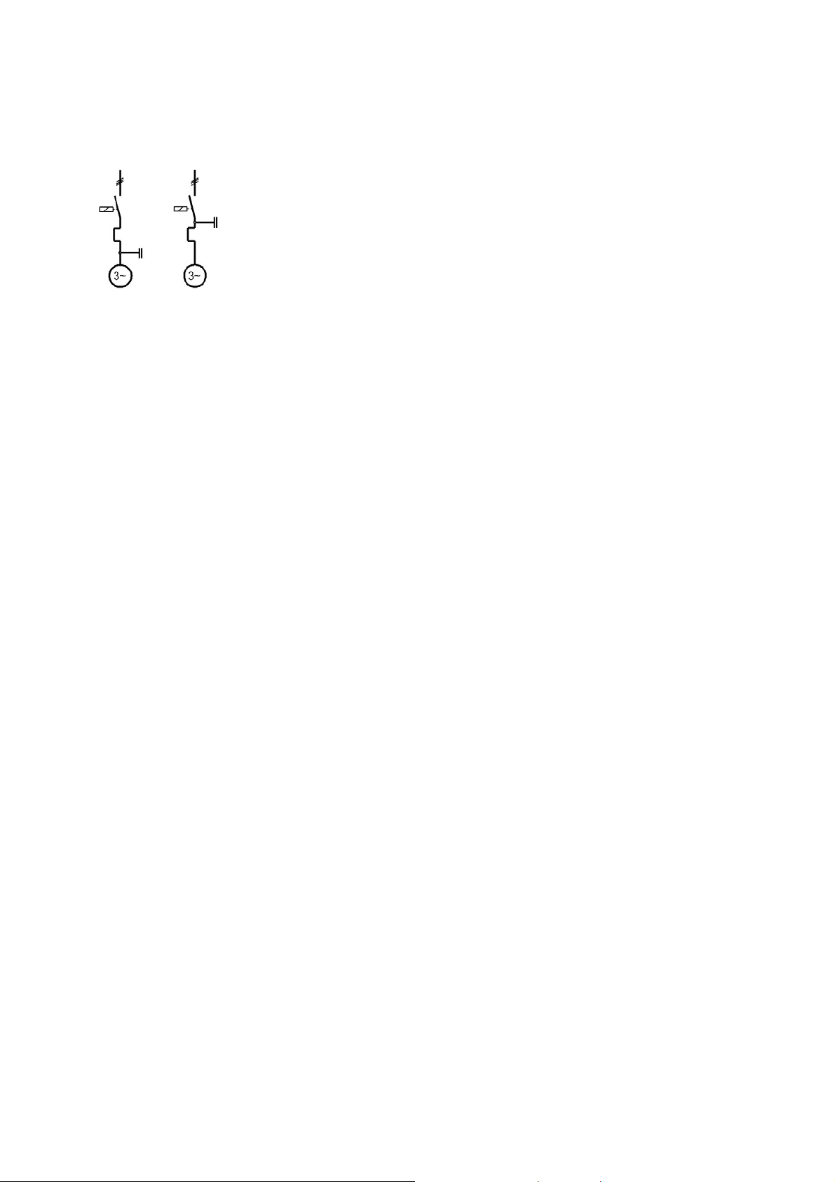
In the case of motors, the capacitors can be connected up- or downstream the motor protection
unit (Fig. 1.5-2). In most cases the capacitor will be connected parallel to the motor (case 1). In
this case th
rated current I
e motor protection unit should be set to a smaller setting current I
as the magnitude of the line current falls due to the compensation:
N
than the motor
e
Case 1 Case 2
Fig. 1.5-2
Individual compensation of motors
I
= (cos φ1/cos φ2) · IN
e
cos φ
cos φ
= power factor of the uncompensated motor
1
= power factor of the compensated motor
2
1.5.1.2 Group compensation
For group compensation each compensation device is assigned to one consumer group. This
may consist of motors or also for example of luminescent lamps that are connected to the mains
via a contactor or a circuit breaker (Fig. 1.5-1 b).
1.5.1.3 Central compensation
Mostly reactive power control units are used for central compensation which are directly
assigned to a main- or sub-distribution station (
many consumers with differing power requirements and variable on-times are instal
Fig. 1.5-1 c). This is especially advantageous if
led in the
network.
Central compensation also offers the advantage that
the compensation device is easy to monitor due its central location,
any retrospective installation or extension is relatively simple,
the capacitive power is continuously adapted to the reactive power requirement of the
consumers and
making allowance for a simultaneity factor a lower capacitance is often required than for
individual co
mpensation.
See IEC 61921; Power capacitors – Capacitor batteries for correcting the low-voltage power
factor
1.5.2 Switching of capacitors
Capacitors form oscillator circuits together with the inductances of the lines and the transformers. During closing, very high transient currents with higher frequencies may flow. Typical
values are 10 ... 30 times the capacitor rated current at frequencies of 2 ... 6 kHz. For this
reason, the switching of capacitors represents a very heavy load on switchgear and can result in
increased contact burn-off or under adverse conditions even welding of the contacts. Especially
when capacitors are switched by contactors, it should be ensured that they are discharged
before switching-on to avoid even higher transient currents and welding of the contacts in case
of adverse phase angles.
A harmonic component in the supply voltage leads to increased current consumption by the
capacitors a
undesired temperature rise, the rated operational current of the contactors, load switches and
circuit breakers shall be higher than the capacitor rated current. Generally this should only be 70
… 75 % of the rated current of the circuit breaker.
LVSAM-WP001A-EN-P - April 2009
nd results in additional heating of the current carrying circuits. To prevent any
1-7
Page 18

Taking into account the aforementioned facts, the switchgear should be dimensioned so that
it does not weld at the high making currents and
that no unacceptable temperature rise occurs during continuous duty.
1.5.2.1 Switching-on single capacitors
If a capacitor with a specific capacity is connected to the power supply, then the making current
is largely determined by the transformer size and by the network impedance to the capacitors,
i.e. from the prospective short-circuit current at the installation site of the capacitor.
The loading of the switchgear increases as
the capacitance of the capacitors increases,
as the rated power of the supplying transformer increases and hence its short-circuit
impedance decreases,
decreasing impedance of the connecting lines.
Table 7 in I
the rated operational current I
−
at
x
valid for
EC 60947-4-1 states the below derivation of capacitor switching capacity I
in relation to the prospective short-circuit current ik:
eAC-3
2
x
⋅=
iI
)6(
kbACe
x
I
ACe
3.13−⋅=
i
k
2
)1( −
)3(
eAC-6b
from
205−⋅>
Ii
)3(
ACek
1.5.2.2 Switching of long, screened lines
Long screened lines have comparatively large capacitances and therefore create high transient
current loads during switching. Typical applications are variable frequency drives. The peak
currents to be expected should be taken into account when selecting switchgear to the same
extent as for the switching of single capacitors.
1.5.2.3 Switching capacitors of central compensation units
If individual capacitors of capacitor banks are switched – for example in reactive power control
units - especially adverse conditions occur at closing of the switchgear contacts as the capacitors already connected to the power supply represent an additional source of energy.
The inrush current is limited by the impedance of the circuit (conductors, capacitor inductance,
inductances
The loading of the switchgear is therefore determined by
the power ratio of the switched capacitors to those already connected to the power supply
and
the impedance of the individual circuit branches
For avoiding welding of t
e.g. be increased, by additional
of the connecting wires).
With special capacitor-contactors or capacitor-c
ces to the power supply via pre-charging resistances, a very high switchable capacitance at a
minimum of interference with the supplying network can be achieved, as the making currents
are specifically limited by the resistances and strongly reduced.
AC-6b is defined in IEC 60947-4-1 as the utilization category for the switching of capacitor
banks.
between the individual capacitor branches).
he switching contacts of the contactors the switchable capacitance can
inductances in the capacitor branches (e.g. a few winding turns
ontactor-combinations that connect capacitan-
LVSAM-WP001A-EN-P - April 2009
1-8
Page 19
1.6 Control circuits, semiconductor load and electromagnetic load
Regarding the specific aspects of the switching of control circuits, also refer to Section 5.
The utilization categories AC-12 to AC-15 for alternating current and DC-12 to DC-14 for direct
current (see
control circui
Tab. 1.1-1) make allowance for the specific loading of switchgear for switching of
ts with semi-conductors or electromagnetic loads. When electromagnets are
switched, for example contactor coils, particular attention is paid to the increased making load
because of the pull-in current of the magnets and the increased breaking load due to the high
inductance of the closed magnets.
In addition to the switching capacity of the contact in the sense of a maximum permitted load,
very often the key criterion in the switching of co
ntrol circuits is contact reliability, i.e. the
capability of a contact or a chain of contacts to reliably switch small signals. This is especially
the case for contacts in circuits of electronic controllers and in the signal range of ≤ 24 V / ≤ 20
mA (also see section
5.3.5).
1.7 Three-phase asynchronous motors
The three-phase asynchronous motor – also known as the induction motor – is the most
frequently used motor type for industrial drives. Especially in the form of a squirrel-cage
induction motor, it dominates the field of industrial electrical drive technology.
1.7.1 Principle of operation
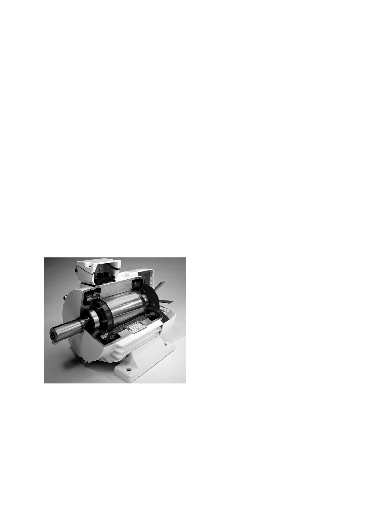
The key functional elements of the three-phase asynchronous motor (see Fig. 1.7-1) are the
fixed stator with a three-phase coil supplied by the three-phase supply network and the revolving rotor. There is no electrical connection between the stator and rotor. The currents in the
rotor are induced by the stator across the air-gap. The stator and rotor are composed of highly
magnetizable dynamo plates with low eddy current and hysteresis losses.
Fig. 1.7-1
Sectional view of a squirrel-cage three-phase motor with enclosed design
When the stator coil is connected to the power supply, the current initially magnetizes the
laminated metal body. This magnetizing current generates a field that rotates with the synchronous speed n
n
n
f = frequency in s
.
s
= 60 · f/p
s
= synchronous speed in min-1
s
-1
p = pole pair number (pole number/2)
For the smallest pole number of 2p = 2, with a 50 Hz power supply, the synchronous speed is
n
= 3000 min-1. For synchronous speeds with other pole numbers and for 50 and 60-Hz power
s
LVSAM-WP001A-EN-P - April 2009
1-9
Page 20

supplies, see Tab. 1.7-1.
Pole
2 4 6 8 10 12 16 24 32 48
number
n
s 50 Hz
n
s 60 Hz
3000 1500 1000 750 600 500 375 250 188 125
3600 1800 1200 900 720 600 450 300 225 150
Tab. 1.7-1
Synchronous speeds for 50 and 60 Hz power supplies
The rotating field of the stator induces a voltage in the coil of the rotor, which in turn creates a
current flow therein. With the interaction of the rotating field of the stator with the conductors in
the rotor through which a current flows, a torque is created in the direction of the rotating field.
The speed of the rotor is always smaller than the synchronous speed by the so-called slip s.
s = (n
-n)/n
s
s
s slip
n
synchronous speed
s
n operational speed
It is only because of this speed differential that a voltage can be induced in the rotor and hence
the rotor curr
ent that is the prerequisite for the generation of the motor-torque. The slip increases with the load torque. Its rated value at the rated load of the motor depends on the rotor
resistance and hence on the energy efficiency of the motor.
The torque curve of the induction motor is characterized by the breakdown-torque. This means
that the torque of the motor increase
s with increasing speed to a maximum value and then
rapidly falls back to zero at the synchronous speed. If the mechanical load of a motor running at
normal service is increased beyond the value of the breakdown torque, it will stall, i.e. it comes
to a halt. The magnitude of the breakdown torque is determined by the electrical reactance of
the motor and hence by the motor’s design. The slip that occurs at breakdown torque can be
influenced by the rotor resistance. This effect is exploited in slip-ring motors by switching on
external resistors (
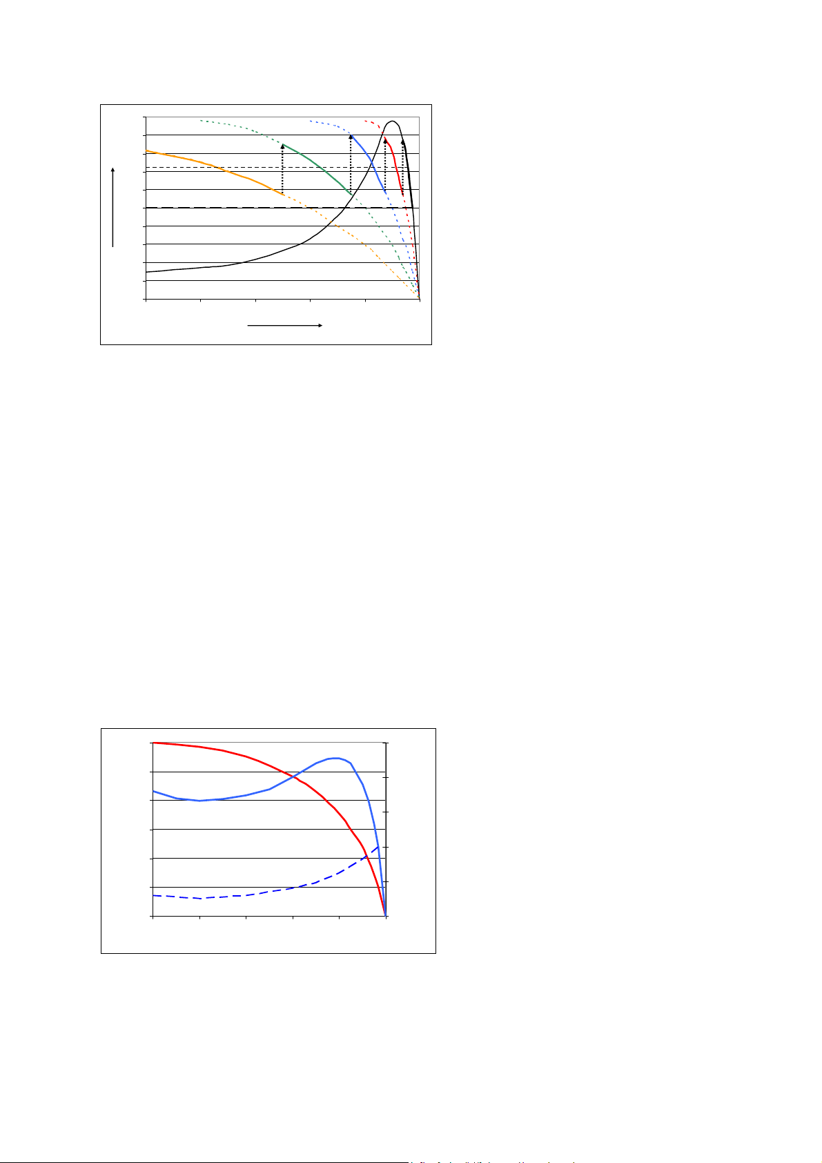
Fig. 1.7-2 and Fig. 1.7-3).
T
b
T
3*R
2
2*R
2
R
2
s
s
10
b
s
3
s
b
b
2
1
Fig. 1.7-2
The torque characteristic of asynchronous motors can quasi be extended by connecting resistors in the
rotor circuit.
breakdown torque
T
b
s slip
breakdown slip
s
b
R
1-10
rotor resistance
2
LVSAM-WP001A-EN-P - April 2009
Page 21
Asynchronous motors behave electrically like transformers. The secondary winding is the rotor
and the mechanical power output of the motor acts on the primary side like a – variable – load
resistance. If no mechanical power output is produced at rest (on initiation of start-up), this load
resistance is zero, i.e. the transformer is in effect secondarily shorted. This leads – depending
on the rotor-internal resistance – to a high or very high current consumption of the motor during
starting. In the case of slip-ring motors, the current consumption is reduced by connecting
external resistors and hence the torque characteristic is adapted to the driven machine. With
squirrel-cage induction motors (see section
torque characteristic ar
e influenced by the design of the rotor cage.
1.7.1.2) the current consumption and hence the
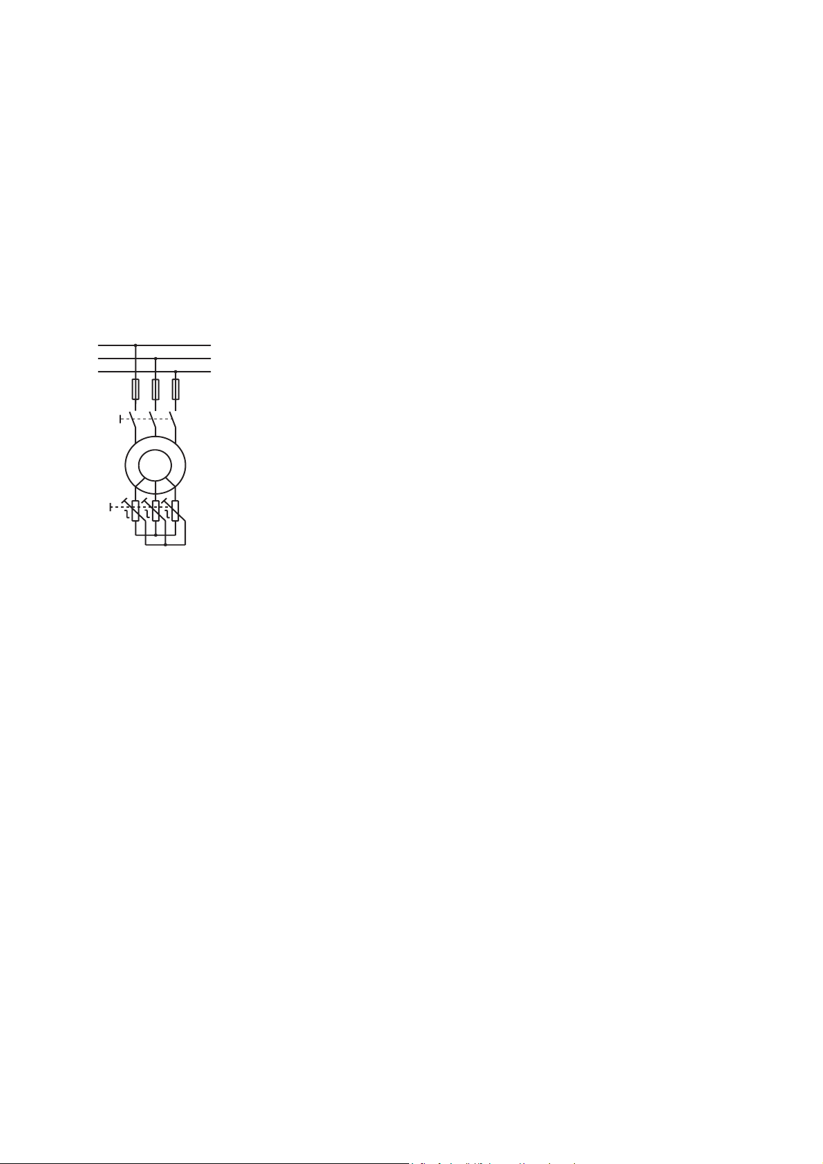
1.7.1.1 Slip-ring motors
With slip-ring motors, the rotor winding is connected to slip rings and terminated with external
resistances. The resistance of the external resistors influences the current flowing through the
rotor and the speed-torque characteristic.
M
3~
Fig. 1.7-3
Principal diagram of a slip-ring motor with external rotor resistances
Slip-ring motors represent the conventional method of controlling starting torque (and the
current consumption) by selection of the rotor resistances. The highest attainable starting torque
corresponds to the breakdown torque of the motor. This is independent of the magnitude of the
rotor resistance. The primary current consumption of slip-ring motors is proportional to the rotor
current. Thanks to these characteristics, slip-ring motors can achieve a high starting torque with
relatively low current consumption.
The external resistors are usually changed in steps during motor startup. The rotor windings are
shorted in normal contin
uous duty. By designing the rotor resistances for continuous duty, it is
even possible to continuously influence the speed, albeit at the cost of high heat dissipation.
LVSAM-WP001A-EN-P - April 2009
1-11
Page 22
2.0
1.8
e
1.6
T/T
1.4
1.2
1.0
0.8
0.6
0.4
0.2
0.0
0.0 0.2 0.4 0.6 0.8 1.0
T
T
av-acc
T
e
≈
4
T
L
T
3
T
0
n/n
T
1
T
2
s
Fig. 1.7-4
Torque characteristic of a slip-ring motor with full-load start-up and stepped change of the rotor resistance
during start-up
T4 … T1 motor torque with series-connected resistance stages (R4>R3>R2>R1)
T
motor torque with shorted rotor windings
0
T
average starting torque
av-acc
T
≈ TL rated torque corresponds to load torque
e
1.7.1.2 Squirrel-cage induction motors
In the case of asynchronous machines with squirrel-cage induction rotors, the rotor consists of a
grooved cylindrical laminated rotor package with rods of highly conductive metal (preferably
aluminum), that is joined on the face side by rings to form a closed cage. The cage – at least in
the case of small motors – is usually cast into the rotor.
To reduce the starting current and influence the starting torque characteristic, the coil rods are
specially designed so th
current displacement. They are usually placed crosswise at an angle to the axis of rotation to
avoid variations in torque and to ensure smooth running characteristics.
Fig. 1.7-5 shows the typical characteristic of the torque and of the current in a cage induction
motor in the speed range from rest to synchronous speed. Material and de
influence the shape of the characteristic curves.
at they create a high rotor resistance at rest and at low speeds by
sign form of the cage
6.00
I
5.00
4.00
e
3.00
I/I
2.00
1.00
0.00
0 20406080100
Δ
T
Δ
T
L
n/ns [%]
2.50
2.00
1.50
1.00
0.50
0.00
e
T/T
Fig. 1.7-5
Typical current and torque characteristic of a squirrel-cage induction m otor bet ween rest and synchronous speed.
current characteristic with delta-connected windings
I
Δ
torque characteristic with delta-connected windings
T
Δ
load torque (example)
T
L
LVSAM-WP001A-EN-P - April 2009
1-12
Page 23
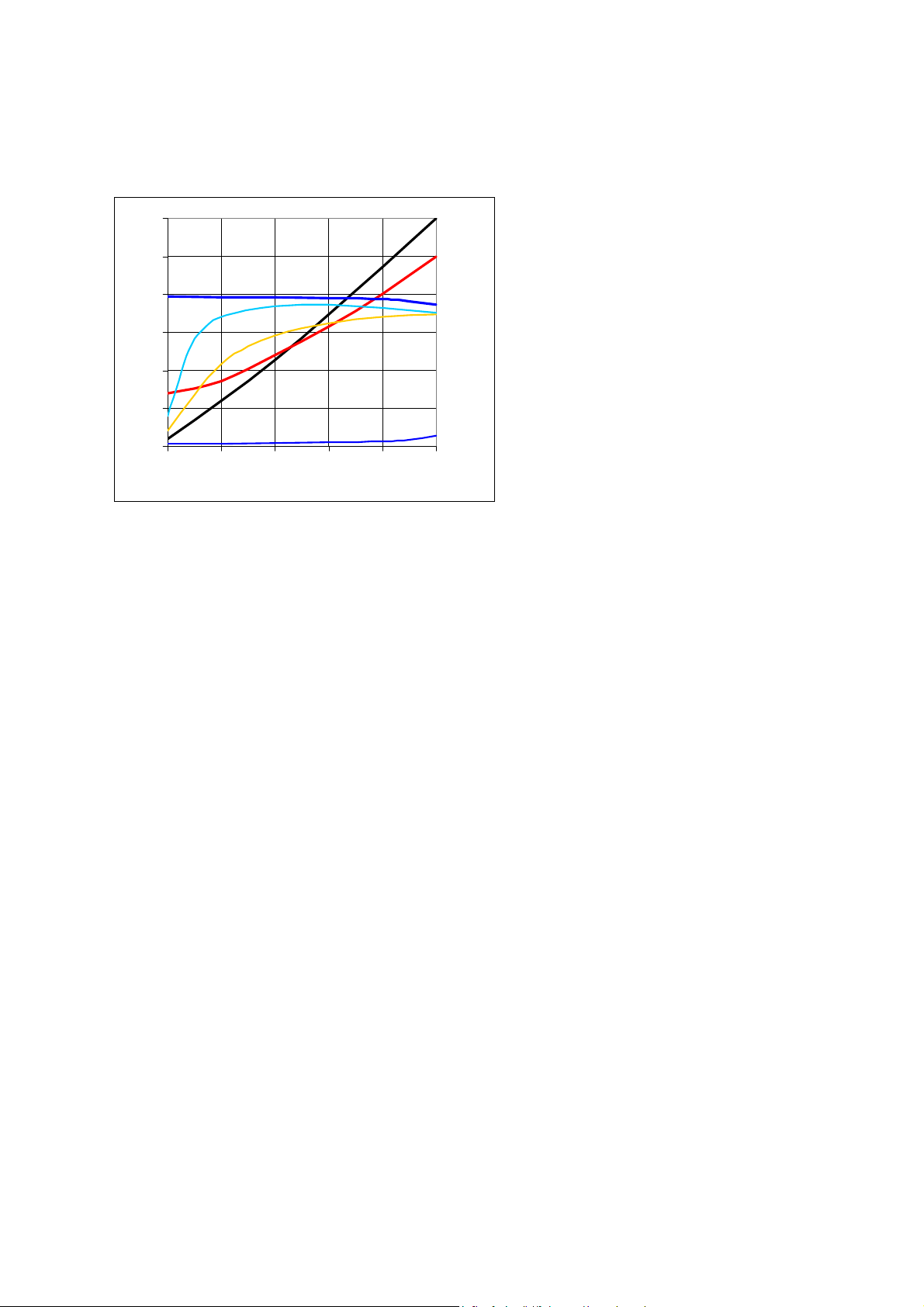
The operating characteristics (Fig. 1.7-6) show that the asynchronous motor has a so-called
I
φ
“hard” speed characteristic, i.
e. the speed changes only slightly with a change in loading. At low
loading, the current consumption approaches the value of the idle running current, which is
basically the same as the magnetization current of the motor.
P
P
1.50
/
1
e
1.25
/
I
e
1.00
n/n
s
0.75
η
cos
0.50
0.25
s
0.00
0.00 0.25 0.50 0.75 1.00 1.25
P
P
/
2
e
Fig. 1.7-6
Operating characteristics of an asynchronous motor as a function of load
n = speed
= synchronous speed
n
s
s = slip
= power intake
P
1
= power output
P
2
P
= rated operational power
e
η = efficiency
s φ = power factor
co
I = current consumption
= rated operational current
I
e
n The speed n only decreases slightly with increasing load. Normal squirrel-cage induction
motors thus have “hard” speed characteristics.
s The slip s in
cos φ The power factor cos φ is strongly d
creases roughly proportionally with increasing load.
ependent on the load and only reaches its highest
value in a state of overload. The power factor is relatively adverse in the part-load range,
as the magnetization is practically constant.
η The efficien
cy η remains relatively constant and in the upper half-load range remains
practically unchanged. It generally reaches its highest value below the rated operational
power P
I The current I increase
falls less strongly and then goes over to the idle running current I
.
e
s proportionally from around the half-load mark. Below this point it
(constant magnetiza-
0
tion)
Starting from the idle running consumption, the power intake P1 increases roughly
P
1
proportionately to the load. In the overload range, its rate of increase is somewhat higher
as losses increase more strongly.
LVSAM-WP001A-EN-P - April 2009
1-13
Page 24

T The torque in the operating range is calculated as follows:
T
=
IU
55.9cos3 ⋅⋅⋅⋅⋅
ηϕ
[]
Nm
n
U voltage across the motor [V]
I current [A]
cosφ power factor
η efficiency of the motor
n speed [min
-1
]
The rated operational currents, starting currents and the torque characteristic of cage induction
motors depend, among other things, on their design, especia
lly the material and form of the
cage, as well as on the number of poles. The specifications provided by the motor manufacturer
apply in each individual case. Typical values for motors can be obtained from the RALVET
electronic documentation.
For switching asynchronous motors, under IEC 60947 the utilization categories AC-2 to AC-4
among others are defined to facilitat
(Tab. 1.1-1). These utilization categories make allowance for the loading
e the user in the selection of suitable contactors
of the switchgear by
the increased making currents when stationary motors are switched on and for the fact that the
effective switching voltage of a running motor is only around 17 % of the rated operational
voltage because the running motor develops a back-e.m.f. (counter voltage to supply voltage).
1.7.1.2.1 High efficiency motors
In the context of the efforts of saving energy and pollution control, the efficiency of electric
motors and drives has become an issue. This on the background of appr. 40% of the global
electricity being used for operating electric motors. The IEC standard 60034-30 (2008) defines
efficiency classes for general purpose induction motors of the power range of 0.75 …375 kW
and with 2, 4 or 6 poles (Tab. 1.7-2). The term MEPS (Minimum Energy Performance Standard)
is being us
minimum level for new motors in the area of the European Union, IE3 may be required in a
further step (minimum requirements, if any, are subject of national legislation).
IEC Class IEC Code EFF Code
Super Premium Efficiency IE4
Premium Efficiency IE3 NEMA Premium
High Efficiency IE2 EFF1 EPAct
Standard Efficiency IE1 EFF2
Below stand Efficiency ‘--- EFF3
1) CEMEP classification (CEMEP = European sector committee of Manufacturers of
Electrical Machines)
ed in this context [25]. It is expected that efficiency class IE2 shall become the
NEMA
1)
Tab. 1.7-2
Efficiency classes for general purpose induction motors according to
IEC 60034-30 (2008) in comparison to the EFF-codes of CEMEP and the codes used by NEMA. IE4 is
not yet defined and reserved for the future.
High efficiency motors that comply with the MEPS standard may have higher starting currents
and cause hi
gher transient current peaks upon switching. The starting torque may be compara-
tively lower for the same starting current, while the breakdown torque may be higher.
When selecting switchgear for starting high efficiency motors, attention should be paid to the
selection of
the proper release class of overload relays (start-up time could become longer at
higher starting current levels). In case of using (current-limiting) circuit breakers the choice of
LVSAM-WP001A-EN-P - April 2009
1-14
Page 25

breakers with high magnetic trip (c.b.’s for transformer protection) may be required for avoiding
nuisance tripping due to high switching transients.
Above factors should particularly be considered in retrofit applications when replacing old
standard motors with new high efficiency motors.
Also, if soft
should be made to ensure the equip
starters are used, the start current may be higher for a given start torque, so a check
ment is rated accordingly. The available start torque may
also need to be evaluated to ensure matching to the load characteristics.
1.7.1.3 Influence of the voltage across the windings
In order to reduce the high current consumption of squirrel-cage induction motors on starting
and the associated, often disruptive, power supply loading and to reduce the high starting
torque when driving sensitive machines, a wide variety of methods is available that is based on
the reduction of the voltage applied across the motor windings. A reduced voltage across a
motor winding results in a proportional reduction in the current flowing through the winding and
consequently in a reduction of the torque developed, by the square of the reduction in the
voltage applied. ½ voltage for example thus means ¼ torque.
A reduction of the voltage across the motor windings can in principle be achieved in one of two
ways:
Reduction of the voltage on the motor while leaving the internal connections of the individual
windings un
Rearranging the connections of the motor windings so that the voltage on the windings is
reduced. Example: Star-delta cir
The ratio of the available motor torque to the motor current flowing is different in above cases.
This is illu
electronic soft starter device (Fig. 1.7-7):
changed (normally connected in delta). Example: electronic soft starter devices.
cuit.
strated with the example of the conventional star-delta circuit compared with the
LVSAM-WP001A-EN-P - April 2009
1-15
Page 26

U
I
U/√3
U
I
p/3
p
Starting method Direct (Δ, delta) Y (star, wye) Soft starting
Current in the pole
100 % 33 % 33 % 57 %
conductor
Torque 100 % 33 % 11 % 33 %
Coil voltage 100 % 57 % 33 % 57 %
U
U
ss
2.50
T/T
2.00
1.50
1.00
0.50
0.00
e
I/I
6.00
e
5.00
4.00
3.00
2.00
1.00
0.00
0 20406080100
T
Δ
I
Y
T
Y
T
SS
I
Δ
I
SS
n/ns [%]
Fig. 1.7-7
nt consumption and torques with direct starting (delta-connected), star-co nnected starting and
Curre
starting with the aid of a soft starting device by reducing the voltage across the motor term inals.
IΔ Current consumption with delta-connected direct starting
T
Torque with delta-connected direct starting
Δ
I
Current consumption for star-connected starting
Y
T
Torque for star-connected starting
Y
I
Current consumption when starting by means of soft starting device at torque T
SS
Y
TSS Torque when starting by means soft starting device and same current consumption
as for star-connected starting
A startup in star circuit develops a higher torque with the same loading on the power supply, as
the voltage across the motor coils is reduced b
y the circuit change. The windings current is at
the same time the pole current, while in the case of a delta-connected motor two windings
currents add vectorial (factor
) to the current of the supplying pole.
3
In relation to the loading of switchgear and its correct selection for starting and operation of
squirrel-cag
the possible
e induction motors with voltage reduction, see Sections 3.3, 3.4 and 3.9, in which
solutions are described in detail.
When using soft starting devices, it should be remembered that the line-side switchgear
operates the input of the
soft starting device, i.e. usually without load. The motor current is
subject to harmonics during start-up, which can lead to undesired tripping, especially where
electronic protective relays are used.
1.7.1.4 Performance of squirrel-cage induction motors with changing fre-
quency
The basic form of the current and torque characteristic is independent of the frequency. In the
sub-synchronous speed range (n = 0 … n
LVSAM-WP001A-EN-P - April 2009
1-16
), the voltage must be reduced in proportion to the
s
Page 27
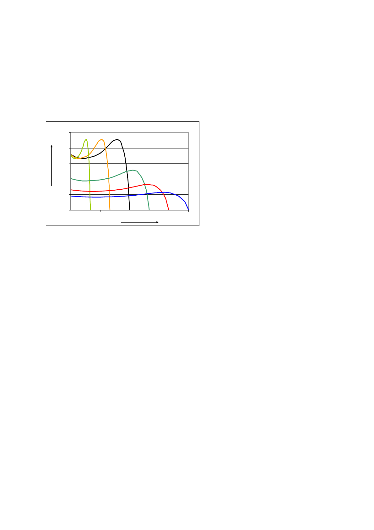
frequency to keep the magnetic flux constant and to avoid saturation of the ferromagnetic
circuits. This means that the magnitude of the breakdown torque remains roughly constant.
Motors that are operated for long periods at lower speeds must be externally ventilated due to
the decreasing efficiency of their internal ventilation.
If the frequency rises above the supply frequency then a constant voltage is usually available
from the frequency converter. This results in a weakening
of the magnetic field with increasing
frequency and consequently in a reduction of the breakdown torque in proportion to the square
of the frequency. Up to the maximum speed, such drives can typically be operated with constant
power output.
2.50
T/T
e
2.00
1.50
1.00
0.50
0.00
0 50 100 150 200
Fig. 1.7-8
Typical torque characteristic with variation of the frequency.
Voltage proportional to frequency in the range 0 … f
Voltage constant in the range > f
n
f/fn[%]
n
When selecting the line-side switching and protective equipment it should be remembered that
frequency converters have large controlled or uncontrolled rectifier circuits on the input-side with
large storage capacitances. This results in high charging current surges and in a high harmonic
content in the current.
LVSAM-WP001A-EN-P - April 2009
1-17
Page 28

LVSAM-WP001A-EN-P - April 2009
1-18
Page 29

2 Switching tasks and selecting the appropriate switchgear
The selection and use of electrical equipment for switchgear assemblies and machine control
units are regulated under the respective national legislation. Within the European Union (EU)
the regulations are based on the CENELEC standards (EN standards) which are largely
identical with the IEC standards. The IEC standards also form the basis of the applicable
regulations in a large number of other countries. In North America, the standards of UL or CSA
as well as the directives of NEMA, NEC etc. have to be applied. All these standards and
regulations have as their common goal to guarantee the safety of electrical installations.
2.1 Electrical equipment complying with standards and matching the application requirements
The standards IEC 60439-1 (Low-voltage switchgear and controlgear assemblies) and
IEC 60204-1 (Electrical equipment of machines) require among other things that the electrical
equipment must correspond to the valid applicable standards. This means that low-voltage
switchgear must be built and tested in compliance with the requirements of IEC 60947. Furthermore, the external design of the electrical equipment, its rated voltages, rated currents, life
span, the making and breaking capacity, the short-circuit withstand capacity etc. must be
suitable for the respective application. If necessary current-limiting protective devices must be
used for protecting the electrical equipment. The coordination of electrical equipment, for
example of motor starters to short-circuit protection equipment must comply with the applicable
norms. When selecting electrical equipment the rated impulse withstand voltages and the
generated switching overvoltages have to be considered.
According to these standards, all devices that are available on the market must comply with the
applicable standards. For the EU and the EEA, this compliance is confir
conformity by the manufacturer and the CE-sign. The same requirements apply to Switzerland,
with the exception that the CE-sign is not compulsory (but is permitted). Other countries have
their own licensing procedures and signs of conformity. So requires China the CCC-mark and
Australia and New Zealand have introduced the C-tick-mark for EMC compliance of electronic
products.
med by a declaration of
Fig. 2.1-1
CE-sign for the EU market (left), CCC-sign for China (center) and C-tick-mark for Australia and Ne w
Zealand
For special applications such as for example shipping, railroads or applications in hazardous
environments where a risk of explosion exists, specific regulations apply in many cases that
usually contain additional requirements beyond the basic IEC standards.
The standards to which the devices have been built and tested are listed in the catalogs. For
low-voltage switchgear (c
markets outside North America, these standards are basically the various parts of the
IEC 60947.
ontactors, motor starters, circuit breakers, load switches etc.) for the
2.2 Basic switching tasks and criteria for device selection
Load circuits include functional components in accordance with Fig. 2.2-1, whereby several
functions can be combined in a single device.
LVSAM-WP001A-EN-P - April 2009
2-1
Page 30
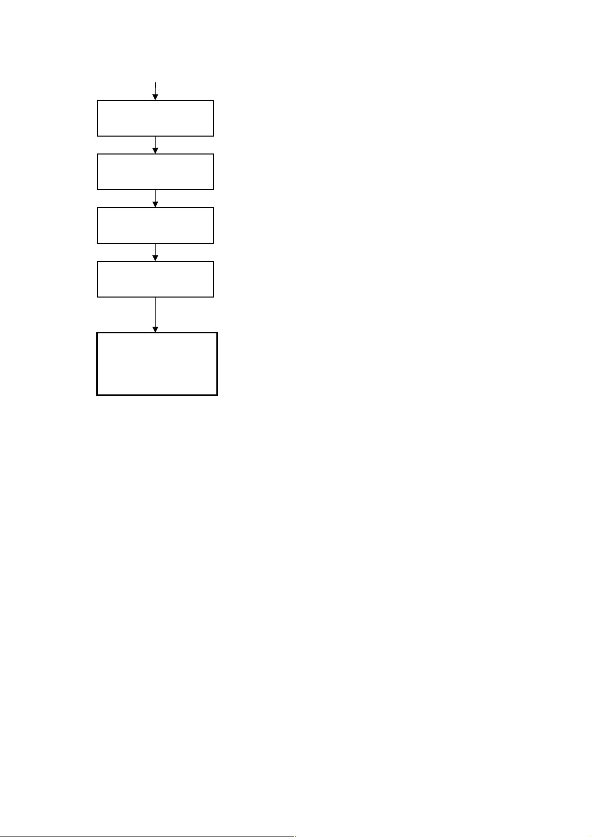
Isolation
Short-circuit
protection
Thermal
protection
Operational
switching
Load
Fig. 2.2-1
Functional elements of a load circuit
Example
Disconnector (Isolator)
Switch disconnector
Circuit breaker with isolating function
Fuse
Circuit breaker
Fuse (line protection)
Circuit breaker with thermal release
Motor protection relay (thermal, electronic)
Contactor
Load switch
Motor protection circuit breaker
Motor
Heater
Lighting
Capacitor
The selection of suitable devices to fulfill the required functions is based on the characteristics
of the load (e.g. rated power and utilization category), the operational requirements (e.g.
switching frequency, required availability after a short-circuit) and the nature of the power supply
(e.g. rated voltage, prospective short-circuit current).
2.2.1 Device types
Various types of device are available for carrying out the switching and protection tasks listed
under 2.2 that are specially designed to fulfill the respective requirements. The various parts of
IEC 60947 (Low-voltage switchgear and controlg
ear) specify the design, performance and test
features of the devices. The most important features of the main device types are presented
below.
2.2.1.1 Disconnectors (isolating switches)
The disconnector is a mechanical switchgear that fulfills in the open position the requirements
specified for the isolation function (IEC 60947-1). The purpose of the isolating function is to cut
off the supply from all or a discrete section of the installation by separating the installation or
section from every source of electrical energy for reasons of safety. The key factor here is the
opening distance. Isolation must be guaranteed from pole to pole and from input to output,
whether this is by means of a visible isolation gap or by suitable design features within the
device (mechanical interlocking mechanism).
A device fulfills the isolating function stipulated under IEC 60947-1 when in the “Open” position
the isolation
circuit of the switchgear. It must also be equipped with an indicator device in relation to the
position of the movable contacts. This position indicator must be linked in a secure, reliable way
to the actuator, whereby the position indicator can also serve as actuator, provided that it can
at a defined withstand voltage is assured between the open contacts of the main
LVSAM-WP001A-EN-P - April 2009
2-2
Page 31

only display the position “Open” in the “OFF” position, when all moving contacts are in the
“Open” position. This is to be verified by testing.
According to IEC 60947-3, an isolator must only be able to make and break a circuit, if either a
current of negligible size is switche
d on or off, or if during switching no noticeable voltage
difference between the terminals of each pole occurs. Under normal conditions it can conduct
operational currents as well as under abnormal conditions larger currents (e.g. short-circuit
currents) for a certain period.
Disconnector
Fig. 2.2-2
Switch symbols
The horizontal line in the switch symbol of the contacts indicates that they fulfill the isolating function
(Load-) Switch Switch-disconnector Circuit breakers
The isolator function can be realized with a variety of devices such as for example in disconnectors, fuse-disconnectors, switch-disconnectors, fuse-switch disconnectors and circuit breakers
with isolating function.
2.2.1.2 Load switches
Load switches (or only “switches”) are mechanical switching devices capable of making,
carrying and breaking currents under normal circuit conditions which may include specified
operating overload conditions and also carrying for a specified time currents under specified
abnormal circuit conditions such as those of short-circuit.
A load switch may have a short-circuit making capacity, however it does not have a short-circuit
breaking capacity (IEC 60947-1 an
circuit withstand capacity), but not be switched-off.
For load switches the range of designs is similarly wide as for isolator switches, for example
“normal” (load) switches, fuse-switch
in all countries.
d -3). Short-circuit currents can be conducted (high short-
es, circuit breakers. Fuse-switches are not legally permitted
2.2.1.3 Switch disconnectors
Switch disconnectors combine the properties of (load) switches and disconnectors.
In this case, too, there are a variety of designs such as “normal” switch disconnectors, fuse-
switch-disconnectors an
d circuit breakers. Fuse-switch-disconnectors are not legally permitted
in all countries.
2.2.1.4 Circuit breakers
See also Section 4.2.2. Circuit breakers are mechanical switching devices, capable of making,
carrying and breaking currents under normal circuit conditions and also making, carrying for a
specified time and breaking currents under specified abnormal circuit conditions such as those
of short-circuit (IEC 60947-2). They thus also fulfill the requirements of (load) switches. Circuit
breakers are often designed so that they can fulfill the requirements for disconnectors.
2.2.1.5 Supply disconnecting devices
IEC 60204-1 (Machine safety – Electrical equipment of machines) requires a supply disconnecting (isolating) device for each incoming source of supply and for each on-board power supply
that completely isolates the machine or the device from the external or internal power supply for
the machine, so that cleaning, maintenance and repair work can be carried out or the machine
can be shut down for longer periods of time.
- A supply disconnecting device must fulfill the requirements of a switch-disconnector as
defined in IEC 60947-3 (load switch
ments of utilization categories AC-23B or DC-23B. Disconnectors are permitted if load shed-
with isolating function) and at the least fulfill the require-
LVSAM-WP001A-EN-P - April 2009
2-3
Page 32

ding is assured by an auxiliary contact before opening of the main contacts of the disconnector. Also circuit breakers with isolating function or other switchgear with isolating function and
motor switching capacity can be used as supply disconnecting devices, provided that they
fulfill the corresponding IEC standards.
- A supply disconnecting device must be manually actuated and have unambiguous “ON” and
“OFF” positions that are clearly marked with “О” and “I”.
A supply disconnecting device must either have a visible contact gap or a position indicator
-
which cannot indicate O
FF (isolated) until all contacts are actually open and the require-
ments for the isolating function as specified under IEC 60947-3 have been satisfied.
- If the supply disconnecting device does not simultaneously
serve as EMERGENCY STOP
device, it may not have a red handle (preferred colors black or gray).
- It must be possible to lock the handle in the “OFF” position (for example with a padlock).
- The supply-side terminals of supply disconnecting devices must be equipped with a finger
protection anti-tamper shield and a
warning sign.
If required, supply disconnecting devices may be equipped with a door interlock device.
The power supply of the below circuits does not necessarily have to be controlled via the supply
disconnect switch:
- Lighting circuits that are required for maintenance work
- Sockets that are exclusively used for service equipment such as drills.
The requirements for supply disconnect switches can be fulfilled by switch-disconnectors, fuse-
switch-disco
nnectors an
d circuit breakers.
2.2.1.6 Supply disconnecting EMERGENCY STOP devices
If there is a real and present danger for man or machine, the dangerous parts of the machine or
the entire machine must be disconnected from the power supply by actuation of an
EMERGENCY STOP device as quickly as possible and brought to a standstill. According to IEC
60204-1 supply disconnecting devices are acceptable as local EMERGENCY STOP devices as
long as they are easily accessible for operating personnel. The below conditions must also be
fulfilled:
- For use as an EMERGENCY STOP device the handle must be red and on a yellow back-
ground.
- The device must be simultaneously able to interrupt the locked-rotor current of the largest
connected motor plus the sum of the rated curr
- It must be able to conduct the total rated operational current of all connected devices.
- The EMERGENCY STOP switch may not break those circuits that could lead to endanger-
ment of the personnel or the machine.
ents of the remaining loads.
LVSAM-WP001A-EN-P - April 2009
2-4
Page 33

2.2.1.7 Summary supply disconnect and EMERGENCY STOP devices
Requirements on supply disconnect devices
(under IEC 6
Operator handle:
- Black or gray handle yes no
- Red handle with yellow background no yes
- Lockable yes yes
Manual actuation from outside yes yes
Easily accessible yes yes
Only one “ON” and “OFF” position yes yes
Position indicator only “О” and “I” yes yes
Lockable in “О” position from outside yes yes
Touch-protected input terminals with warning symbol yes yes
Tab. 2.2-1
Summary of requirements on switches for use as supply disconnect devices and supply disconnect/EMERGENCY STOP devices
0204-1)
Supply
disconnect
devices
Supply
disconnect/
EMERGENCY
STOP devices
2.2.1.8 Fuses
Fuses have a short-circuit breaking capacity and in the form of full-range fuses are also suitable
for overload protection of conductors and certain loads. For details see Section 4.2.1.
2.2.1.9 Devices for thermal protection
See Sections 4.1.2, 4.2 and 4.2.4.
Devices for thermal protection are divided into two groups:
Devices that evaluate the thermal risk to the protected object and provide a protective
disconne
ction in one unit (for example full-range fuses, MCB’s, circuit breakers, motorprotection circuit breakers, electronic motor control devices with integrated motor protection)
and
Devices that exclusively evaluate the thermal risk to the protected object but for protective
shutdown control a power switching
device (usually a contactor). These include for example
overload relays and thermistor (PTC) protection devices.
2.2.1.10 Contactors
Contactors are designed for operational switching and - in accordance with the required high
mechanical and electrical life span - use relatively low contact forces. Accordingly they have no
short-circuit switching capacity and must be protected against the effects of short-circuit
currents by series-connected short-circuit protective devices. See Section
2.3.4.5.
2.3 Parameters for the correct selection and sizing
For the specific application of low-voltage devices additional parameters should be taken into
account such as for example the application ambient temperature, the expected device life
span, any influences from moisture, mechanical impacts and vibrations etc., to name only a few
of the most important. Tab. 2.3-1 provides a summary of the most important parameters when
selecting devices. Some of the specific features
are looked at in more detail below.
LVSAM-WP001A-EN-P - April 2009
2-5
Page 34

Parameter
Rated isolation voltage U
i
Rated operational voltage Ue (<Ui)
Rated impulse withstand voltage U
Rated operational current I
e
imp
Utilization category
Short-circuit withstand capacity / short-circuit
protection
Rated short-circuit making capacity I
Rated short-circuit breaking capacity Icu, I
cm
cs
Cut-off current
Let-through energy (Joule integral)
Rated short time current I
cw
Short-circuit coordination
(Type 1, Type 2) with fuses or circuit breakers
Thermal load
Ambient temperature
Operational overcurrents
(for example heavy-duty starting)
Life span
Frequency of operation
Rated frequency / harmonics
Safety clearances
Mounting position
Pollution degree
Overvoltage category
Protective separation
Site altitude
Shock and vibration
Humidity / climatic loading
Chemical ambient influences
Radioactive radiation
UV radiation
External form / IP degree of protection
Details chapter
2.3.1
2.3.2
2.3.3
2.3.2
2.3.2
2.3.4
2.3.4.6.1
2.3.4.6.2
2.3.4.2
2.3.4.4
2.3.4.1
2.3.4.4
2.3.4.3
2.3.4.5.2
2.3.5
2.3.5.1
2.3.5.2
2.3.6
2.3.7
2.3.8
2.4.3
2.3.9
2.3.10
2.3.3
2.3.3
2.3.11
2.3.12
2.3.13
Fuses
Disconnectors
ers
Starters
Circuit break-
Contactor
Load switches
P P P P P
P P P P P
P P P P
P P P P P
P P P P
P P P
P P
P P
C C
C C
C C C
P
P P P P
C C C C C
C C C C C
C C
C C
C C C C C
P P P
C C
A A A A A
A A A A A
A A A A A
A A A A A
A A A A A
A A A A A
A A A A A
A A A A A
A A A A A
A A A A A
Tab. 2.3-1
Selection criteria for low-voltage switchgear for main circuits
P … Primary selection factors
C … Complementary selection factors
A … Additional criteria
LVSAM-WP001A-EN-P - April 2009
2-6
Page 35

2.3.1 Rated isolation voltage Ui
Ui is the voltage on which the selection of creepage distances of electrical equipment and the
dielectric tests are based. U
must always be bigger than (or at least the same as) the voltage
i
that is applied to the electrical equipment and is thus always larger than or the same size as the
rated operational voltage U
. With the selection of Ue is thus Ui (in the responsibility of the
e
device manufacturer) correctly selected, whereby the pollution degree and the overvoltage
category should be taken into account.
2.3.2 Rated operational voltage Ue, rated operational current Ie and utilization category
The rated operational voltage Ue is always to be considered in association with the corresponding rated operational current I
suitability of an item of electrical equipment for a certain application. For utilization categories
see Section
Corresponding to the universal applicability, an item of electrical equipment can be assigned a
variety of different datasets (for example I
for a certain operational voltage). Common values for rated operational voltages for switchgear
can be seen in Tab. 2.3-2. With 3-phase supply systems, the delta (phase to phase) voltage of
the power supply applies.
d.c.
V
6 6
12 12
24 24
36
48 48
60
72
96
110 110
220 230 230/400
440 400/690
Tab. 2.3-2
Preferred rated voltage
(L-N/L-L). Copyright © IEC, Geneva, Switzerland. www.iec.ch
1.1.
Supply voltages Supply voltages for three-phase
277/480
and the utilization category. These three variables determine the
e
for various operational voltages or I
eAC-3
4-wire or 3-wire systems
a.c.
V
s for supply systems in accordance with IEC 60038 ed. 6.2 and industrial practice
50 Hz
V
120/208
1000
60 Hz
V
240
347/600
600
eAC-3
and I
eAC-4
2.3.3 Rated impulse withstand voltage U
The rated impulse withstand voltage U
is a measure for the dielectric strength. From the point
imp
imp
of view of the user it is important, as the required dielectric strength among other things
depends on the pollution degree of the installation site and the overvoltage category, i.e. the
proximity to the feeding supply network. With respect to the pollution degree see Tab. 2.3-3.
Tab. 2.3-4 shows as an excerpt from Table H.1 of IEC 60947-1 Annex H t
overvoltage category on the applicable impulse withstand voltage U
imp
he influence of the
. The rated impulse
withstand voltage is for example important in circuit breakers that are often deployed on the
distribution level or also on the supply level.
LVSAM-WP001A-EN-P - April 2009
2-7
Page 36

6.1.3.2 Pollution degree
The pollution degree (see 2.5.58) refers to the environmental conditions for which the
equipment is intended.
NOTE 1 The micro-environment of the creepage distance or clearance and not the environment of the equipment determines the
effect on the insulation. The micro-environment might be better or worse than the environment of the equipment. lt includes all
factors influencing the insulation, such as climatic and electromagnetic conditions, generation of pollution, etc.
For equipment intended for use within an enclosure or provided with an integral enclosure, the
pollution degree of the environment in the enclosure is applicable.
For the purpose of evaluating clearances and creepage distances, the following four degrees of
pollution of the micro-environment are establishe
d (clearances and creepage distances
according to the different pollution degrees are given in Tables 13 and 15):
Pollution degree 1:
No pollution or only dry, non-conductive pollution occurs.
Pollution degree 2:
Normally, only non-conductive pollution occurs.
Occasionally, however,
a temporary conductiv-
ity caused by condensation may be expected.
Pollution degree 3:
Conductive pollution occurs, or dry, non-conductive pollution
due to cond
ensation.
occurs which becomes conductive
Pollution degree 4:
The pollution generates persistent conductivity caused, for instance, by conductive dust or by
rain or snow.
Standard pollution degree of industrial applications:
Unless otherwise stated by the relevant product standard, equipment for industrial applications
is generally for use in pollution degree 3 environment. However, other pollution degrees may
be considered to apply depending upon particular applications or the micro-environment.
NOTE 2 The pollution degree of the micro-environment for the equipment may be influenced by installation in an enclosure.
Standard pollution degree of household and similar applications:
Unless otherwise stated by the relevant product standard, equipment for household and similar
applications
Tab. 2.3-3
Pollution degree according to IEC 60947-1 ed. 5.0.
Copyright © IEC, Geneva, Switzerland. www.iec.ch
is generally for use in pollution degree 2 environment.
LVSAM-WP001A-EN-P - April 2009
2-8
Page 37

Maximum value of
erati
rated op
voltage to earth
a.c. r.m.s. or d.c.
onal
V
300 220/380, 230/400,
600 347/600, 380/660,
1000 - 12 8 6 4
Nominal voltage of the
supply system
(≤ rated insulation
voltage of the
equ
ipment)
a.c. r.m.s.
V
240/415, 2607440
277/480
400/690, 415/720
480/830
Preferred values of rated impulse withstand
voltage (1,2/50 μs) at 2 000 m
Overvoltage category
IV III II I
Origin of
Installation
(service
entrance)
level
6 4 2.5 1.5
8 6 4 2.5
Distributi
circuit level
Tab. 2.3-4
Correspondence between the nominal voltage of the supply syste m and rated impulse withstand voltage
of the device with protection by surge-arrestors according to IEC 60099-1
Excerpt from Table H.1 of IEC 60947-1 ed. 5.0 Annex H
Copyright © IEC, Geneva, Switzerland. www.iec.ch
on
kV
(applia
equipment)
Load
level
nce,
Specially
protected
level
2.3.4 Short-circuit withstand capacity and short-circuit protection
See also Section 4.1.3.
Adequate protection against the consequences of a short-circuit is one of the most fundamental
safety measures for electrical equip
of property. For operational reasons it is often desirable that devices survive short-circuits
largely unscathed so that they may become operational again as quickly as possible afterward.
The specification of coordination types for starters is also related to this requirement.
The short-circuit withstand capacity of electrical equipment is usually defined by stating the
largest permitted short-circuit protect
circuit breaker). Current limiting fuses and modern current limiting circuit breakers make a major
contribution to the economical rating of devices, as they strongly reduce the thermal and
dynamic loading of devices and equipment connected downstream.
Loading in the event of a short-circuit is defined by the Joule integral (I
current (I
) and the short-time current (Icw).
D
ment. This affects both the protection of persons as well as
ive device (for example permissible fuse or permissible
2
t value), the cut-off
LVSAM-WP001A-EN-P - April 2009
2-9
Page 38

u
u,i
u
B
i
K
i
D
i
p
t0 t
V
t
A
tk
2
I2t=
t
K
dti.
∫
k
t
Fig. 2.3-1
Basic characteristic of current and voltage when clearing a short-circuit with a current limiting circuit
breaker
u System voltage
Electric arc voltage
B
u
B
Prospective peak short-circuit current
i
p
Limited short-circuit current
i
K
Cut-off current
i
D
Inherent system delay
t
0
Electric arc hesitation time
t
V
Rise time
t
A
Total break time
t
K
2.3.4.1 Joule integral I2t
The I2t-value is a measure of the thermal loading of the electrical equipment in the shorted
circuit. Fuses and current limiting circuit breakers limit the short-circuit current to values
significantly below those of the uninfluenced current and thus reduce the thermal loading of the
devices in the shorted circuit, for example of the contact system of a contactor connected
downstream. The rule of thumb is that the Joule integral of the short-circuit protective device
must be smaller than the permissible I
to be protected.
2
t-value of the conductor and of the electrical equipment
2.3.4.2 Cut-off current ID
The cut-off current is the largest instantaneous value of the current that a current limiting shortcircuit protective device allows through. As the action of the force of the electrical current is
proportional to the square of the current, the cut-off current is critical in ensuring the required
mechanical strength of connected electrical equipment. This is particularly relevant for the
design of bus systems (number and strength of the supports). IEC 60439 takes this circumstance into account by dispensing from the requirement of verification of the short-circuit
withstand capacity for cut-off currents ≤ 17 kA.
2.3.4.3 Rated short-time withstand current lCW
Like the Joule integral, the short-time withstand current lCW is a measure of the thermal load
capacity. It is important for circuit breakers of category B (suitable for selectivity) and is usually
stated as the 1s-current (preferred values under IEC 60947-2 are 0.05, 0.1, 0.25, 0.5 and 1 s). A
conversion of I
I
The I
cw1
-value is of importance when for selectivity reasons the breaking action of circuit
cw
breakers is delayed. The circuit breakers in the shorted circuit must be able to carry the shortcircuit current until the delay time has expired and then shut down the shorted circuit. For circuit
LVSAM-WP001A-EN-P - April 2009
2-10
currents for other durations is permitted according to the equation
cw
2
· t1 = I
2
· t2 = const.
cw2
Page 39

breakers with I
l
≥ 30 kA is required.
CW
≤ 2500 A, IEC 60947-2 requires lCW ≥ 12 · In, at least 5 kA. For In > 2500 A
n
2.3.4.4 Current limiting protective equipment
If the short-circuit withstand capacity of electrical equipment is lower than the prospective shortcircuit current at the installation site, its loading must be reduced in the case of a short-circuit by
upstream current limiting protective equipment to the permissible magnitude. For this purpose
fuses or current limiting circuit breakers may be chosen.
2
The I
t- and iD-values of this protective equipment are – usually in diagrams – stated as a
function of the prospective short-circuit current I
that these quantities vary with the operating voltage. For fuses, limit-curves can be found in the
diagrams for the cut-off current for the largest and without direct current component (see
example
current for the largest direct current
Fig. 2.3-3). As the time of occurrence of a short-circuit is coincidental, the cut-off
component is critical for engineering (i.e. most unfavourable
time point of occurrence of the short-circuit).
(see example Fig. 2.3-2). It should be noted
cp
Fig. 2.3-2
-values and I2t-values as a function of the prospective short-circuit current I
i
D
cp
When the cut-off current is limited to ≤ 17 kA, in accordance with IEC 60439-1 no verification of
the short-circuit withstand capacity for the downstream circuits is required. This relates in
particular to the mechanical strength of the conductors. For the protection of electrical equipment (for example of motor starters) smaller cut-off currents may also be required.
LVSAM-WP001A-EN-P - April 2009
2-11
Page 40

[A]
D
Cut-off current i
Prospective short-circuit current I
cp
Fig. 2.3-3
Example of an i
-diagram for fuses as a function of the prospective short-circuit curre nt Icp
D
1) Peak short-circuit current without direct current component
2) Peak short-circuit current with maximum direct current component
2.3.4.5 Coordination of electrical equipment
The coordination of electrical equipment refers to the assignment of short-circuit protective
devices to contactors or starters with respect to the effects of a short-circuit on these devices.
Distinction is made between two types of coordination:
- The coordination of the trip characteristic of the overload relay (if present) with the protective
characteristic of the short-circuit pro
tective device in respect of the switching capacity of the
contactor
- The coordination between the short-circuit protective device, the contactor and the overload
relay with respect to the destructive
effect of a short-circuit and their operability afterward.
2.3.4.5.1 Coordination in respect of the switching capacity of the contactor
(overcurrent selectivity)
The coordination between the release characteristic of the overload relay and the short-circuit
protective device takes account of the switching capacity of the contactor. Contactors are
designed for the operational switching of loads and are not able to switch-off currents of shortcircuit level. The coordination of the devices must ensure that for currents above the switching
capacity of the contactor the short-circuit protective device shuts down before the overload relay
is responding and dropping-out the contactor (
Fig. 2.3-4 and Fig. 2.3-5).
LVSAM-WP001A-EN-P - April 2009
2-12
Page 41

I >
I >
I >
a)
M3~
b)
M3~
c)
M3~
M3~
d)
M3~
Fig. 2.3-4
Types of load feeders (with electromechanical switchgear)
a) Fuse, contactor, motor protection relay
b) Circuit breaker with magnetic release, contactor, motor protection relay
c) Circuit breaker with motor protection characteristic, contactor
d) Operational switching and circuit breaker function combined in one contact system
For starters that are protected by circuit breakers with motor protection characteristic, no
coordination with respect to the overcurrent selectivity is required, as circuit breakers switch-off
in the event of overloads and short-circuits.
10000
t
1000
100
10
1
1
0.1
5
4 3
2
0.01
0.001
110
7
6
100
I
x
e
Fig. 2.3-5
Short-circuit coordination of switching and protective devices. Circuit breakers with motor protection
characteristic are used as an alternative to fuse/overload relay.
1 Motor starting current
2 Trip characteristic overload relay
3 Destruction limit curve overload relay
4 Trip characteristic circuit breaker with motor protection characteristic
5 Time/current-characteristic fuse (alternative to circuit brea ker)
6 Rated breaking capacity of the contactor
7 Welding area of the contactor
2.3.4.5.2 Coordination with respect to the operability after a short-circuit
The coordination of contactor and overload relay, if any, with a short-circuit protective device
with respect to the operability of starters after a short-circuit is determined by the destructive or
damaging effect of the short-circuit current on the starter components. Basic requirement –
regardless of coordination type – is that neither persons nor equipment may be endangered.
LVSAM-WP001A-EN-P - April 2009
2-13
Page 42

- Coordination type 1 permits damage to the starter so that further operation may only be
possible after repair or replacement.
- With coordination type
2 the contactor or starter must be suitable for further use after the
short-circuit. Slight welding of contacts is acceptable. An early replacement of the starter
components is usually required (depending on the severity of the short-circuit) due to the
erosion of contact material by the short-circuit current, however this can be carried out at an
operationally convenient time.
- Coordination ty
pe “CPS” requires in accordance with IEC 60947-6-2 that a load feeder
continues to be usable after a short-circuit, in order to maximize operational continuity. The
guaranteed residual electrical life span based on a new device is 6000 cycles. In this case
too, the replacement of the starter components as in coordination type 2 is required and
may be carried out at a time that is convenient from an operational viewpoint. Load feeders
under coordination type “CPS” can be realized in any design (see also
Fig. 2.3-4).
Type “1” Type “2” Type “CPS”
Finding and rectifying cause of short-circuit X X X
Checking starter X X
Replacing devices X 1) 1)
Separating welded contacts, if any X
Resume operation X X X
Planned maintenance (device replacement) X X
Tab. 2.3-5
The selection of the coordination type with respect to duration of the interruption to operation
1) Replacement of fuses, if used
2.3.4.6 Short-circuit switching capacity
The switching capacity is the r.m.s value of a current at a given power factor cos φ as well as a
given rated voltage at which a switchgear or a fuse can still shut-off under specified conditions
in an operationally safe way. Both the short-circuit making capacity as well as the short-circuit
breaking capacity of circuit breakers must be larger than or equal to the prospective short-circuit
current at the place of installation. If this is not the case, then a suitable backup protection (for
example a fuse) should be provided to ensure the required switching capacity of the devicecombination. Data regarding devices for backup protection are given in the technical documentation.
2.3.4.6.1 Rated short-circuit making capacity Icm
The rated short-circuit making capacity Icm is a quantity that according to regulations must be in
a certain ratio to the rated ultimate short-circuit breaking capacity I
and that has to be guaran-
cu
teed by the device manufacturer. This is not a variable that must be considered by the user,
however it ensures that a circuit breaker is in the position to connect onto a short-circuit – and to
disconnect it subsequently.
2.3.4.6.2 Rated short-circuit breaking capacity Icu and Ics
IEC 60947-2 makes distinction between the rated ultimate short-circuit breaking capacity ICU
and the rated service short-circuit breaking capacity I
- Rated ultimate short-circuit breaking capacity I
I
is the maximum breaking capacity of a circuit breaker at an associated rated operational
CU
voltage and under specified conditions. I
is expressed in kA and must be at least as large
CU
as the prospective short-circuit current at the site of installation.
Circuit breakers that have switched-off at the level of the ultimate short-circuit breaking capacity, are reduced serviceable afterwards and should at least be checked regarding functionality. There may be changes in the overload trip characteristic and increased temperature
rise due to the erosion of contact material.
LVSAM-WP001A-EN-P - April 2009
2-14
CU
:
CS
:
Page 43

- Rated service short-circuit interrupting capacity I
I
values are usually lower than the values for ICU. Circuit breakers that have been switch-
CS
CS
:
ing-off at the level of the service short-circuit breaking capacity continue to be serviceable
afterward. In plants in which interruptions to operations must be kept as short as possible,
product selection should be carried-out based on I
CS
.
- Breaking capacity of fuses
The same applies to fuses as to circuit breakers
with respect to the I
: at the given rated
CU
operational voltage, the rated breaking capacity must be at least as large as the prospective
short-circuit current at the site of installation.
2.3.5 Thermal protection
Compliance with the permissible operational temperatures of electrical equipment is both a vital
safety factor as well as critical regarding its effective life span. The rate of ageing of plastics
increases exponentially with their operational temperature.
For all electrical equipment, limiting values for the load currents are defined, compliance with
which should be ensured by suitable protective devices and
measures (fuses, overload relays,
temperature sensors).
2.3.5.1 Ambient temperature
Electrical equipment is designed for operation in defined temperature ranges. The upper
temperature limit is of special importance, because practically all electrical equipment dissipates
power and hence produces heat. The selection of the devices must consider the device’s
ambient temperature and the permitted load at this temperature.
The normal ambient temperature range under IEC 60947, IEC 60439 and IEC 60204 is –5 °C to
+40 °C with a 24-hour average that does not exceed +35 °C. It should be noted that
values of the current load capacity unless otherwise stated are related to an ambient temperature of +40 °C. With other (higher) temperatures the loads should be reduced in accordance
with manufacturer specifications or larger devices should be chosen. For industrial switchgear,
loading specifications are often provided for an ambient temperature of +55 or +60 °C.
The lower limit of the operational temperature may be critical with electronic devices and it
should be assured by provision of h
eating that temperature does not fall below. In conjunction
with moisture (freezing), low temperatures can also adversely affect the operability of electromechanical devices.
Rated operational values designated as “open” apply for devices used in free air, while values
designated “enclosed” a
pply for devices installed in an enclosure of small size specified by the
manufacturer. The reference ambient temperature for “open” is the temperature of the ambient
air of the device, even if this is installed in a box or cabinet. The reference ambient temperature
for “enclosed” is the air-temperature of the housing environment. The ambient temperature of
the device in the housing is higher because of the effect of its own heat dissipation. In practice
this means for example that for a contactor “open” at 60 °C I
= 20 A will be stated and “en-
th
closed” at 40 °C the same value, because due to heating in the housing the contactor is
subjected to the same immediate ambient temperature of 60 °C. At 40 °C “open” the same
contactor can for example conduct 25 A.
In switchgear, in which the temperature in the cabinet (see Software TRCS) is calculated or
measured, the data for “open”, that is in t
he immediate device environment (microclimate)
should be taken into account when selecting the devices. It should be ensured by temperature
monitoring and cooling measures that the actual temperature does not exceed the reference
value on which the component selection is based.
the rated
2.3.5.2 Operational overcurrents, heavy-duty starting
Operational overcurrents occur especially when motors are started. Switchgear such as
contactors or load switches should be rated so that it can cope with the regularly occurring
overcurrents without difficulty, assuming it has been selected in accordance with the corresponding utilization category. Motor starts that cause normal motor protection relays of trip
LVSAM-WP001A-EN-P - April 2009
2-15
Page 44

class 10 (tripping between 4 and 10 s at 7.2 · I
A
A
A
A
A
A
A
A
) to trip are considered as heavy-duty starts. In
e
these cases overload protective relays with slower trip characteristics should be selected. See
also
1.7.1.2.1.
In addition the load capacity of the switchgear should be checked.
The load capacity of contactors and circuit breakers without thermal release basically depends
on their size (cross-se
ction/mass of the conducting parts). It therefore varies from device to
device. Up to a starting time of around 10 s for direct starting, the load of the devices during
starting needs not to be checked. Furthermore the admissible load capacity can be obtained
from the technical documentation (catalog, RALVET; see example
should be al
lowed between successive heavy-duty starts that provide sufficient time for the
Fig. 2.3-6). Rest times
switchgear (see RALVET) and the motor to cool down before the next loading.
Heavy starting and
regular short-time duty
Contactor size
100
10
23
43
30/37
09/12/16
95
60/72/85
210A250A300A420
180A140A110
I
e(AC-3)
Max. starting time / load period [s]
1
10 100 1000 10000
Starting current / short-time current [A]
Fig. 2.3-6
Example of a loading diagram for contactors for heavy-duty starting of squirrel-ca ge induction motors
2.3.6 Life span
The life span of switchgear basically depends on the size of the load and the number of
switching cycles. Instead of a time span, with electromechanical switchgear reference is usually
made to the number of operations, as the ageing mainly depends on the stress during switching
and less on the on- and off-phases between. The maximum number of operations is usually
determined by the wear of heavily loaded components – in contactors, load switches and circuit
breakers especially of the contact system.
For switchgear, the mechanical and electrical life spans are separately defined. The mechanical
life span sta
life span states the number of operations for a certain size of electrical loading and a certain
utilization category.
In electronic devices, the life span is usually less dependent on the number of operations but
rather on the working te
power adapters) age more quickly at higher temperatures. This is why it is recommended to
install electronic devices in the cooler parts of switch cabinets.
Ageing is also a problem with fuses, especially in the context of switching of motors. Full-range
fuses (gL, gG
example to repeated short-term melting. When using them with motors with the latters’ high
starting currents, it should therefore be ensured that the starting current does not raise the
tes the number of possible operations without electrical loading, while the electrical
mperature. Thus for example electrolytic capacitors (for example used in
) have a soldered joint for tripping in the overcurrent range that may age due for
LVSAM-WP001A-EN-P - April 2009
2-16
Page 45

temperature of this solder joint beyond a certain limit. Fuse manufacturers provide information
on the smallest fuses that can be selected in relation to given motor currents and starting times.
2.3.6.1 Prospective service life
The prospective service life of switchgear is the number of years, months or weeks that it should
complete under the foreseen service conditions in 1-, 2- or 3-shift operation without the replacement of spare parts. It depends on the frequency of operation and the total number of
individual switching operations. For the latter in addition to the mechanical also the electrical life
span of the devices must be selected accordingly (see Section 2.3.6.3). The required parameters can be determined by means of
∗∗∗=
f
n
tot
S
=
n
Y
f
S
Total number of operations (life span)
n
tot
f
S
h
D
d
Y
n
Y
n
f
S
n
=
Switching operations per hour
Operating hours per day
Operating days per year
Number of years (life span)
ndh
YYD
tot
tot
∗∗
dh
YD
∗∗
dhn
YDY
the below formulae:
2.3.6.2 Mechanical life span
The mechanical life span of switchgear is the total number of possible switch operations without
electrical switch loading. It depends on the design, the masses moved, the forces and accelerations occurring. Large load switches and circuit breakers operate with high contact forces and
large masses, and therefore have a comparatively short mechanical life span. On the other
hand, contactors operate with relatively small contact forces and thus achieve longer mechanical life spans.
After the mechanical life span has expired, the devices must be replaced. This life span is only
rarely achiev
ed during the foreseen service life. In a few cases, where the complete mechanical
life span has to be used, it should be ensured that it is not reduced by adverse ambient
conditions, installation position and – in the case contactors – by an excessive control voltage.
2.3.6.3 Electrical life span
The electrical life span for switchgear is the number of possible switching operations under
operational conditions. After this number has been reached, the parts subject to wear must be –
wherever possible – replaced. With small devices, the entire device must be replaced.
Depending on the application, the loading and the resulting erosion of the contacts varies
widely. This is influ
dominant role:
- Breaking current
- Making curr
- Voltage
- Power factor cos φ with alternating current
- Time constant
- Frequency of operation
- Malfunctions in the plant and on other devices (contact chatter)
- Ambient conditions (climate, temperature, vibrations)
Usually the electrical life span determined under test conditions is presented in diagrams as a
function of the rated op
in contactor selection. In practical operation, the loads are usually lower, as the running motor
usually carries a current that is below the rated operational current. In the case of longer inching
enced by the following conditions, whereby the first mentioned play the
ent
τ with direct current
erational current. These values may generally be used without hesitation
LVSAM-WP001A-EN-P - April 2009
2-17
Page 46

operation, the starting current has already dropped somewhat by the time the motor is switchedoff. This usually compensates for the effect of any disregarded adverse conditions.
For the most common applications of contactors the electrical life span is presented in the
product documentation with various diagrams:
- AC-1 Non-inductive or slightly inductive loa
ds, for example resistance furnaces
(small making current and cos φ higher than with AC-3, however full recurring voltage
on switching off)
- AC-3 Squirrel-cage induction motors: Starting, switching off motors during running
- AC-2 Slip-ring motors: Startin
- AC-4 Squirrel-cage motors: Starting, plugg
(high making current, breaking of the motor rated current)
g, switching
off
ing, inching (high making and breaking current at
full voltage)
- Mixed service of slip-ring motors, e.g.
AC-3
90 %
AC-4 10 %
With the curves Fig. 2.3-7 for AC-3 and Fig. 2.3-8 for AC-4 the expected electrical life span for
specific applications
can be determined. These curves also can be used to determine the
electrical life span for any application (for example jogging motors with very high or especially
low starting current and any mixed service).
Contactor size I
e(AC-3)
[A]
Fig. 2.3-7
Example of a diagram for determining the electrical life span of contactors as a function of the rated
operational current I
The diagram applies up to 460 V, 50/60 Hz.
for utilization category AC-3.
e
Example
Background:
Squirrel-cage induction motor 7.5 kW, 400 V, 15.5 A, AC-3 (switching off only when running),
operating cycle 2 minutes
ON / 2 minutes OFF, 3-shift operation, expected service life 8 years.
Objective:
Selection of the contactor
Solution:
2 min ON +
2 min OFF
= 15 switching operations/h. This results for 3-shift operation over 8
years in around 1 million switching operations.
From diagram Fig. 2.3-7 yields for a rated operational current of 15.5 A and 1 million required
switching operations the
contactor C16 (electrical life span approx. 1.3 million switching
operations).
LVSAM-WP001A-EN-P - April 2009
2-18
Page 47

Contactor size I
Fig. 2.3-8
Example of a diagram for determining the electrical life span of contactors as a function of the rated
operational current I
The diagram applies up to U
for utilization category AC-4.
e
=690 V, 50/60 Hz.
e
e(AC-3)
[A]
Example
Background:
Squirrel-cage induction motor 15 kW, 400 V, 29 A, plugging, switching off rotor at standstill at
I
= 6·Ie, expected life span = 0.2 million switching operations.
A
Objective:
Rating of starting and braking contactors.
Solution:
The starting contactor (circuit making only) is selected according to the maximum permitted
rated power at AC-3 (see Fig. 2.3-7): C30.
The brake contactor is selected according to the maximum permitted rated operational power at
AC-4 and 0.2 million swi
tching opera
tions according to Diagram Fig. 2.3-8: C72.
For mixed service, i.e. service of the contactor with AC-3 and AC-4 switching operations, the life
span results from the sum of the loadings. In the
catalogs, diagrams for certain %-rates of AC-4
operations, for example 10 %, are provided. The RALVET electronic documentation is available
for determining the life span for other percentage rates, or direct inquires must be made.
If in practice the electrical life span was considerably shorter than desired, there are several
possible caus
es and explanations:
- More switching operations than expected, e.g. operated by extremely sensitive controller.
- More frequent inching than expected, e.g. unskilled operation.
- Permitted frequency of operation exceeded, e.g. chattering contacts
- Short-circuits, e.g. switching pause too short for reversing or star-delta starters.
- Synchronization with the supply voltage. Semiconductors as
controllers
could for example
always switch off at the same phase angle and act in the same direction of current-flow
(results in one-sided material migration to the contacts like in direct current control).
Assessment of the contacts
In conjunction with the electrical life span, the question often arises of assessment of contacts
after a certain service pe
riod for continued serviceability. At least with large contactors, the
contacts can be inspected.
Already after the first few switching operations, there are clear signs of burn-off on the contact
surface. After a relatively small number of switching operations, the entire contact surface
becomes roughened an
d blackened. Black deposits and traces of arc extinction can be seen on
LVSAM-WP001A-EN-P - April 2009
2-19
Page 48

the surrounding components. Serrated edges and loss of contact material toward the arcing
A
chamber are also normal.
The end of the contact life span is really reached when larger areas of the contact plating have
broken off or
there is a danger of the contact touching the substrate material. The below figures
are intended as an aid for an assessment of contacts.
B
Sectional
views
A
B
Fig. 2.3-9
Contacts of a power contactor at various stages of the life span with AC-3 loading
Fig.s above: Contacts in new state
Fig.s in center: Contacts after approx. 75 % of the electrical life span; Contact material partially eroded;
contacts still operable
Fig.s below: Contacts at the end of their life span; Substrate material visible, contact material eroded
down to the substrate; further use would lead to contact welding and excessive tempera ture rise.
The pictures on the right show the contact state in long section. The images of the va rious life span
phases originate from various contacts, as the contacts can no longer be used once the section has been
cut.
2.3.7 Intermittent and short-time duty, permissible frequency of operation
With continuous duty, i.e. with constant loading over hours, days and longer, the switchgear
reaches its thermal equilibrium. The individual components reach their steady-state tempera-
LVSAM-WP001A-EN-P - April 2009
2-20
Page 49

tures. The rated loading values refer from a thermal view point to continuous duty at a certain
ambient temperature (see Section 2.3.5). IEC 60034-1 defines the continuous duty of motors at
the rated operational cur
rent until the steady-state temperature is reached as the rated service
type S1.
In practice in addition to the continuous duty there is a large number of loading situations with
changing loads. In inter
mittent operation, load-phases and de-energized breaks alternate in
regular sequences. The load periods and intervals are so short that the components of the
switchgear (and of the load) do not reach their thermal equilibrium neither during the warming
nor the cooling phases. For motors the three rated service types S3, S4 and S5 are defined for
intermittent operation in IEC 60034-1 (S3…constant load; S4…with additional starting load;
S5…with additional starting and braking load).
Fig. 2.3-10
Current loading and temperature rise during intermittent duty
Current loading during intermittent duty S4
I
S4
δ
Heating and cooling during intermittent duty S4
Δ
S4
For meaning of other symbols see Fig. 2.3-11
In short-time duty the current flows for a limited time so that steady-state temperature is not
reached. The de-energized interval after the load-period is however so long that the devices can
nearly cool down to the ambient temperature. In IEC 60034-1 the short-time duty for motors is
named rated service type S2.
Fig. 2.3-11
Current loading and temperature rise in short-time duty S2
Load duration
B
t
B
De-energized interval
t
L
Duration of a switching cycle
t
S
Thermal continuous current
I
th
Current loading with short-time duty
I
S2
Maximum permissible temperature rise
Δδ
max
Temperature rise with thermal continuous current
Δδ
S1
Heating and cooling with short-time duty
Δδ
S2
Comment: In short-time duty a higher temperature than in continuous duty is permitted!
LVSAM-WP001A-EN-P - April 2009
2-21
Page 50

With intermittent or short-time duty, the loading current can be higher than in continuous duty,
without resulting in the permitted temperature being exceeded. Therefore, for example, for
switching ohmic loads and rotor contactors for slip-ring motors smaller contactors can be
selected than would be required according to the rated current of the load.
When switching squirrel-cage induction motors, transformers, capacitors and incandescent
lamps, the required contact rating is
however the main selection criterion. The size of contactors
for these applications is therefore determined by the rated operational current and the respective utilization category for all service types.
2.3.7.1 Intermittent duty and relative ON-time
In order to define a specific intermittent duty, in addition to the value of the current either the
load and cycle time or the frequency of operation per hour together with the relative ON-time are
preferably stated.
I
B
t
B
t
S
Fig. 2.3-12
Intermittent duty
t
B
⋅=
II
BS
t
S
I
Average current loading (r.m.s. value during a switching cycle and hence also during
S
the whole service time) [A]
Current during period under load [A]
B
I
B
B
Load duration [s]
t
B
Switching cycle = load duration + de-energized interval [s]
t
S
ED relative ON-time = t
B/tS
[%]
I
S
The relative ON-time – usually expressed as a percentage – is the ratio of the load duration to
the cycle-time, whereby the cycle-time is the sum of the load duration and the de-energized
interval.
The average current loading I
must always be somewhat lower than the thermal continuous
S
current, so that the temperature rise peaks at the end of each period under load do not exceed
the permitted values. With stator contactors of slip-ring motors, especially with short switching
cycles, the higher current during the starting time (see
heating effect of the ele
ctric arcs must be taken into account.
Fig. 2.3-10) as well as the additional
At high frequency of operation the heating effect of the starting current and the switching arc is
greater than the cooling
effect of the de-energized intervals so that contactors with higher
ratings must be chosen than would normally be required according to the rated operational
current. The selection is made based on the graphs for the permissible frequency of operation.
Even without electrical loading, the frequency of operation of contactors is limited by the
maximum p
ermissible temperature of the coil or the electronic coil control circuit, if any. The inrush currents of the coil (Fig. 2.3-13) make a considerable contribution at higher frequencies of
operation to the overall heating of the
coil and of the contactor. This applies both for alternating
current and for direct current magnets with series resistance or contactors with double-windingcoils (economy circuit) and also to electronic coil control circuits.
LVSAM-WP001A-EN-P - April 2009
2-22
Page 51

A
Fig. 2.3-13
Coil current at closing a contactor a.c. magnet
Rated current of coil
I
S
Inrush current of coil (depending on contactor 6... 15 · IS)
I
S1
T1 ON-command (coil circuit closed)
T2 Magnet closed
The permissible frequency of operation of conventional coils can be exceeded short-time
without risk, as the time constants for the heating of coils is 5 to 20 minutes depending on
contactor size.
True direct current magnets do not exhibit in-rush currents. Therefore with these the ON and
OFF delay times, which in this case
are notably longer, determine the maximum frequency of
operation.
With electronically controlled coils, the permissible frequency of operation is determined by the
thermal load capacity of the electronic components and may
not be exceeded.
With electrical loading, the temperature rise of the contacts must also be taken into account for
determining the permissible frequency of operation. Although, heat is dissipated during
the deenergized intervals, the contacts are additionally heated to a considerable degree by arcing and
by the starting currents when switching motors. The permissible frequency of operation is
therefore dependent on the relative ON-time, the size and duration of the motor starting current
and on the breaking current. Corresponding diagrams are provided in the catalogs for typical
applications (
Fig. 2.3-14).
Contactor size I
9/12/16 A
23/30/37/43 A
60/72/85
e(AC-3
[A]
Fig. 2.3-14
Example of a frequency of operation characteristic for contactors. T he frequency of operation for small
loads is limited by the temperature rise of the coil.
At higher frequencies of operation, the contacts are predominantly loaded by the starting
currents. This also applies to motor windings.
LVSAM-WP001A-EN-P - April 2009
2-23
Page 52

When switching motors – assuming that the motor is correctly rated for the stated frequency of
operation – it should be checked whether the overload protection device is suitable for the high
frequency of operation and that it does not release early or late. See also Section
4.1.2.
Note
equ
Inadvertently exceeding of the permissible fr
ency of operation is the most frequent cause of
prematurely eroded contactor contacts. If the contactors are made to “chatter” by rapidly
recurring interruptions of the coil current and at the same time switch high currents – e.g.
starting currents of motors – this results in heavy wear that can lead to welding or destruction of
the contacts.
It is often difficult to identify faults in switching cir
cuits as they can have a variety of causes, for
example:
- Loose terminals
- Gradually opening cont
acts of thermostats, pressure sensors, limit switches etc.
- Strongly bouncing control contact
- Slowly activated control switch
- Incorrectly programmed PLC
- Drop of control voltage
2.3.8 Rated frequency and harmonics
See also Section 2.4.3.
The normal supply frequencies for all catalog data are 50 and 60 Hz. Also for direct current
applications
whether higher (for example 400 Hz in military and aviation applications) or lower (for example
16 2/3 Hz on railroads) the loading of switching and protective devices changes. An examination
of the suitability for the respective application and the determination of the performance data for
the specified loadings are essential prerequisites for correct device selection.
Also in applications in which harmonic contents of the current occur – for example in variable
speed drives – the performance data of switching
corresponding values are provided in the technical data. With other frequencies,
and protective devices may be affected.
2.3.9 Safety clearances
For devices that generate electric arcs, especially for circuit breakers, safety clearances to
adjacent devices, conductors or conductive surfaces may be required, as the arc gases
(plasma) can be ejected with very high temperature and speed. The safety clearances specified
in the manufacturer documentations must be observed to avoid risks to persons and equipment.
If the required safety clearances are not observed a secondary short-circuit may be created on
the input side of a circuit breaker – for example when conductive gas is emitted during switching
off a short-circuit. Such short-circuit would be switched off by the next short-circuit protective
device on the supply side, whose rated current usually would be significantly higher. The
destructive energy of the electric arc and the danger to persons and material are correspondingly high.
The safety clearances are usually stated in the dimensional dr
example Fig. 2.3-15).
awings for the devices (see
LVSAM-WP001A-EN-P - April 2009
2-24
Page 53

Fig. 2.3-15
Example of a dimensional drawing stating the required safety clearances to condu ctive materials; the
safety clearances do not apply to connected, insulated conductors
Clearances between devices may also be necessary from a thermal viewpoint, in order to
ensure adequate heatflow and compliance with the operationally permissible temperatures.
These specifications are also available in the catalogs or on request. See also Section 6.1.
2.3.10 Mounting position
Certain electrical devices such as contactors and circuit breakers may be subject to restrictions
with respect to the permissible mounting position (Fig. 2.3-16) or their operational parameters
may change with the mounting posit
mounting type is permissible at all, typically exhibit longer dropout times and are sensitive to
impacts in vertical direction. Suspended contactors (overhead position) may require higher pullin voltages, which pushes the lower limit of the tolerance range of the control voltage upward.
ion. Thus standing contactors (table-mounted), if this
Fig. 2.3-16
Permissible mounting position of a contactor (exampl e).
The gray zone on the side indicates the required clearance from grounded components.
Specifications on the permissible mounting positions can be found in the dimensional drawings
of the devices. With respect to the influence on the operational parameters of installation in
positions that differ from the standard position (suspended, upright), it is recommended to
inquire directly to the manufacturer.
2.3.11 Protective separation
For protection against electric shock in conjunction with the use of electronic control devices,
protection by SELV (Safety Extra Low Voltage) and PELV (Protective Extra Low Voltage) is
increasingly being chosen. The maximum voltage levels for SELV and PELV are 50 V a.c. and
120 V d.c. (with exception of special applications with lower limit values).
In circuits with SELV and PELV, all devices that are included in the circuit must be isolated from
other power circuits
double creepage distances and the next higher impulse voltage withstand level U
applies for example for auxiliary circuits of switchgear with respect to their power circuits
(Fig. 2.3-17).
by insulation corresponding to that of a safety transformer. That means
. This
imp
LVSAM-WP001A-EN-P - April 2009
2-25
Page 54

Fig. 2.3-17
Protective separation between power and control circuits
This is usually achieved by a reduction in the rated operational voltage. This means that for
example a contactor suitable for 690 V can be used at 400 V in SELV and PELV circuits. The
approval of SELV and PELV circuits requires design features that guarantee that protective
separation is maintained even in the event of faults (for example broken parts). When selecting
switchgear for SELV and PELV circuits attention must be expressly paid to the declaration of
protective separation at the respective operational voltage.
2.3.12 Site altitude
The site altitude and hence the air density play a role with respect to the cooling conditions, the
dielectric withstand voltage and electric arc extinction. A site altitude of up to 2000 m is considered as normal in accordance with IEC 60947. For higher altitudes, some performance data of
the devices must be reduced. With power electronics devices in many cases load reductions
already apply from 1000 m. In the product catalogs specifications should be found about the site
altitudes on which the performance data is based.
For contactors, bimetallic thermal overload relays and circuit breakers with bimetallic tripping
mechanisms, approximate values for the reduction of ratings at altitude
provided in
Tab. 2.3-6.
Altitude above sea level [m]
[ft]
Contactors
Reduction factor for I
Reduction factor
for I
AC-2, IAC-3, IAC-4
AC-1
n·I
up to 415 V n·I
up to 500 V n·I
up to 690 V n·I
Bimetal overload relays 1)
Adjustment factor on the
n·I
rated operational current of
the motor 2)
1) Also applies for circuit breakers with bimetal tripping mechanisms. The trip characteristics of electronic protective
relays usually do not change with the site altitude
2) Reduction of the rated operational currents of motors in relation to the site altitude in accordance with specifications of the motor manufacturer to be considered additionally
2000
6600
e
e
e
e
e
1.0 0.95 0.9 0.85
1.0 0.95 0.9 0.85
1.0 0.93 0.85 0.78
1.0 0.87 0.77 0.65
1.0 1.06 1.11 1.18
3000
10000
s above 2000 m are
4000
13000
5000
16500
Tab. 2.3-6
Correction factors for applications at altitudes over 2000 m
2.3.13 Shock and vibration
Low-voltage switchgear is designed and tested for loading by shock and vibration for normal
industrial usage. This includes the usual stress in operation, for example, as a consequence of
vibrations during switching of contactors.
LVSAM-WP001A-EN-P - April 2009
2-26
Page 55

In applications with increased stress by shock and vibration such as for example in vehicles, in
rail transport or on ships a variety of measures is required to protect the devices from the
immediate influence of externally generated shock and vibrations. In the simplest case, by
optimization of the mounting position. In case of doubt, the manufacturer should be consulted.
2.4 Specific application conditions and switching tasks
2.4.1 Parallel and series connection of poles
2.4.1.1 Parallelling
Parallel connection of poles in switchgear increases its thermal load capacity. It should be
remembered that the resistances of the individual poles vary due to contact burn-off, deposits
etc. The current does not distribute itself equally among the parallel poles, but corresponding to
their particular impedances.
A reduction factor for the total load must be applied to avoid overloading of the individual
contacts. In
- with 2 parallel poles I
- with 3 parallel poles I
The making and breaking capacity remain in parallel circuits the same as for single contacts , as
frequently one contact is opening or closin
switching work. Therefore it is not possible to increase the contact rating of contactors for
switching motors and capacitive loads by parallel connection of contacts. Tab. 2.4-1 shows the
switching ca
Three pole
Making capacity 12·I
practice the following values for the permissible total current can be calculated with:
= 1.8 x Ie
e2
= 2.5 x Ie
e3
g first and therefore must take the largest part of the
pacity based on the total current with 2 and 3 contacts connected in parallel.
switching
Æ I
e
e
2 poles in
parallel
Æ I
e2
1)
= 1.8 · I
e
(12·Ie2)/1.8 = 6.7·I
e2
3 poles in
parallel
Æ I
e3
1)
= 2.5 · I
(12·Ie3)/2.5 = 4.8·I
e
e3
Breaking capacity 10 · I
1)
Voltage across each contact U = Ue/√3
Tab. 2.4-1
Making and breaking capacity of contactors as a multiple of the rated operational current I
switching and for two and three parallel poles
e
(10·Ie2)/1.8 = 5.6·I
e2
(10·Ie3)/2.5 = 4·I
e3
for three pole
e
For this reason contactor poles should only be connected in parallel for switching resistive loads
(utilization category AC-1). Where possible they should only be connected in parallel by means
of copper bars fed in the center in order to ensure symmetrical current distribution and good
heat dissipation. For small contactors special connecting bridges are available.
Any short-circuit currents that occur are distributed between the poles depending on the given
pole resistances. In the
case of circuit breakers with parallel contacts, it may happen at small
short-circuit currents that the operating current of undelayed electromagnetic short-circuit
releases is not reached. Consequently such a short-circuit is only switched off by the thermal
release after a delay. The pick-up threshold for undelayed short-circuit breaking rises approximately by a factor given by the number of parallel poles.
2.4.1.2 Series connection
When two or three poles of switchgear are connected in series (Fig. 2.4-1), the advantages
include the following:
- Increased dielectric withstand voltage
- Improved s
- Higher operating voltage
- Larger contact life span
witching capacity
LVSAM-WP001A-EN-P - April 2009
2-27
Page 56

These advantages are exploited by using three-pole contactors and circuit breakers for switching single-phase alternating current and above all direct current. The limit for higher operating
voltage is determined by the rated insulation voltage that may in no event be exceeded. The
permissible current loading of poles connected in series is the same as for individual poles.
1-pole 3-pole
2-pole
Fig. 2.4-1
Examples of diagrams for poles connected in series. Where grou nded power supplies are used (top
graph) with loads switched on both sides, it should be noted that ground faults can lead to bridging of
contacts and hence to a reduction in the breakable voltage.
The overload trip characteristics of devices with thermally delayed bimetal tripping mechanisms,
such as circuit breakers and overload relays, apply when all three bimetal strips are equally
loaded. This is guaranteed by connecting the circuits in series. In devices that are sensitive to
phase failure, series connection of all circuits is compulsory. With electronic motor protection
relays, it may be necessary to deactivate the phase failure protection.
The impact of series connection of circuits when switching direct currents is dealt with in
Section 2.4.2.
For the effect of series connection of circuits on switching frequencies < 50 Hz and > 60 Hz see
Section 2.4.3.
2.4.2 AC switchgear in DC applications
Switchgear designed for alternating current can carry at least the same rated continuous
operational DC current. With direct current the skin effect in the circuits disappears and none of
the specific effects associated with alternating currents such as hysteresis or eddy current
losses occur.
DC devices that are operated at low voltage can be switched by AC switchgear without difficulty,
as their direct current switching cap
current.
With voltages in excess of around 60 V, the direct current switching capacity of AC switchgear
with double-breaking co
or three circuits in series (
ntacts (for example contactors) decreases strongly. By connecting two
Fig. 2.4-1) this limit can be raised to twice or three times the voltage.
The reason for the reduced switching capacity with DC compared with AC is the absence of the
current zero crossover t
hat with AC supports the quenching of the electric arc. The electric arc
in the contact system can continue to burn under larger direct voltages and thus destroy the
switchgear. With direct voltages, the contact erosion and hence also the contact life span differ
from those at alternating voltage. The attainable values for direct current are specifically tested
and documented.
With direct current, the load affects the switching capacity more strongly than with alternating
current. The energy stored in the ind
an electric arc. Hence with a strongly inductive load (large time constant L/R) the permissible
switching capacity for the same electrical life span is smaller than with an ohmic load due to the
much longer breaking times.
acity at low voltages is practically the same as for alternating
uctance of the load must largely be dissipated in the form of
LVSAM-WP001A-EN-P - April 2009
2-28
Page 57

Overload release units
The reaction of bimetal strips heated by the operating current depends on the heat generated in
the bimetal strips and in
their heating coil, if any. This applies equally for alternating current and
direct current. The trip characteristic can be somewhat slower with direct current as there are no
hysteresis and eddy current losses. With overload releases that are sensitive to phase failure,
all three circuits should always be connected in series to prevent premature tripping.
Overload releases heated via current transformers are not suitable for direct current. Also
electronic ov
erload relays in most cases cannot be used in direct current applications as the
current is measured via current transformers and their functionality is tailored to alternating
current.
Short-circuit releases
Electromagnetic overcurrent releases can be used with direct current. However the tripping
threshold cu
rrent is som
ewhat higher than with alternating current.
Undervoltage and shunt-trip releases
Undervoltage and shunt-trip releases operate with magnet circuits. Special designs are required
for direct voltage.
2.4.3 Applications at supply frequencies < 50 Hz and > 60 Hz.
Effect of harmonics
Low-voltage switchgear is designed for a supply frequency of 50 ... 60 Hz. If it is desired to use
them for other rated frequencies the following device characteristics should be checked:
- thermal load capacity of the circuits,
- switching capacity,
- life span of the contact system,
- release characteristics,
- operating characteristics of magnetic and motor drives.
The effect of higher frequencies on the performance of low-voltage devices should be consid-
ered both in
networks wit
where current-harmonics occur. Such current-harmonics occur if the supply voltage contains
harmonics or if non-linear consumers are connected. Such consumers may for example be
compensation devices for luminescent lamps that operate in the range of saturation or devices
with phase angle control. With consumers with phase angle control and with frequency converters (Inverters; see Section
supply. The harmonic content can be
current consumption increases with increasing frequency. Special attention should be paid to
this factor in individually compensated motors and a correction of the current settings of the
protective relay may be required.
In applications in which current-harmonics arise, the effect of the harmonics (for ex
additional heating effects) is added to that of the basic frequency. This can be especially critical
in devices that contain coils or ferromagnetic materials (bimetal heating coils, magnetic releases
etc.).
In the case of loads with connection to the neutral conductor (e.g. single-phase loads such as
luminescent lamps, small power ada
the formation of a zero-sequence-system that may lead to thermal overloading. This should also
be taken into account in the use of 4-pole switchgear.
h higher basic frequencies (for example 400 Hz) and also in cases
3.10) harmonics with frequencies up to several kHz may arise in the
increased by capacitors connected to the supply, whose
ample
pters etc.), a high harmonic content can result because of
2.4.3.1 Effect of the supply frequency on the thermal load
In contrast to direct current, with AC the current does not flow evenly through the cross-section
of a conductor. The current density falls from the surface inward. This effect – known as the skin
effect – increases with increasing frequency so that at very high frequencies the core of the
LVSAM-WP001A-EN-P - April 2009
2-29
Page 58

conductor is virtually de-energized and the current only flows in a relatively thin layer at the
conductor surface.
This means that with increasing frequency, the resistance of the circuit increases. In addition,
due to magnetic inductio
n, higher hysteresis and eddy current losses are created in adjacent
metal parts. Especially ferromagnetic materials (arc extinguishing parts, screws, cage terminals,
magnets, base plates) can reach unacceptably high temperatures. Special care should be taken
at frequencies > 400 Hz.
Because of the variable cross-sections of the conductive parts as well as the different nature
and distances to adjacent metal parts, additiona
l heating effects and especially the local
overtemperatures vary according to device type. This has the following consequences for the
load capacity of the switchgear and the switchgear combinations.
Individual clarification is required for each individual application as a general statement cannot
be provided due to the widely differing design fea
tures, especially at frequencies > 400 Hz.
Load capacity of contactors, load switches and circuit breakers
Devices that are designed for a frequency of 50/60 Hz can, from a thermal viewpoint, be used
for the same rated current at a lower frequency. Approximate values for permissible operational
currents are stated in Fig. 2.4-2. The actual reduction factors vary according to design and the
rated current range of th
e devices. It should be noted that cage-type terminals have an adverse
effect on heating at higher frequencies.
1.00
0.90
0.80
0.70
eAC-1(50/60Hz)
/I
0.60
eAC-1(f)
I
0.50
0.40
0.30
0.20
0.10
0.00
medium size
devices
(≈100 A )
big devices
big devices wi t h
cage-type
terminals
10 100 1000 10000
small dev i ces
f [Hz]
Fig. 2.4-2
Approximate values for permissible operational currents AC-1 of contactors, load switches and circuit
breakers at higher frequencies relative to I
at 50…60 Hz
e
Higher frequencies and installation provisions
For installation at higher frequencies, special attention must be paid to the effects of current
distribution (skin effe
ct), hysteresis and eddy current losses:
The conductors to be connected should be rated according to the higher frequency (larger
cross-section, flat or tube conductors). The load capacity of circuits at higher frequencies can be
roughly estimated by help of Fig. 2.4-3. It depends on the geometry of the rails and their
arrangement and should be measured separately in each ind
ividual case. The conductors
should be positioned as far as possible from conductive (especially ferromagnetic) parts, to
minimize inductive effects.
LVSAM-WP001A-EN-P - April 2009
2-30
Page 59

1.00
0.90
0.80
e(50Hz)
/I
0.70
e(f)
I
0.60
0.50
0.40
0.30
0.20
0.10
0.00
10 100 1000 10000
f [Hz]
Fig. 2.4-3
Approximate load capacity of busbars at higher frequencies [12]
Load capacity at 50 Hz
I
e50
Load capacity at frequency f
I
ef
In order to reduce losses, no cage-type terminals should be used. This is especially important
with currents > 100 A!
For single phase loads over 400 Hz, the two outer poles of contactors should be used in parallel
for the feed line and the middle pole for the return line. This results in a partial mutual compensation of the magnetic induction.
2.4.3.2 Effect of the supply frequency on the switching capacity
The starting currents of motors for higher frequencies are sometimes higher than those at
50/60 Hz. At 200 Hz this can result in 15 times the rated current and at 400 Hz up to 20 times.
The power factor may be significantly worse than for motors at 50/60 Hz. Allowance should be
made for the increased making currents when selecting devices.
Switching capacity of contactors and load switches
When breaking a.c. circuits, the clearance between open contacts must be sufficiently deionized during the curre
half cycle. At higher frequencies, the increase of the voltage after the zero crossover is usually
faster. The electric arc duration per half cycle and hence the ionization of the distance between
open contacts is however smaller. Therefore contactors and load switches (zero-point interrupters) up to around 400 Hz have virtually the same switching capacity as at 50/60 Hz.
Insofar as the making currents are permissible (see above) – a reduction of the rated current I
according to Fig. 2.4-2 for contactors and load switches is only required because of the larger
thermal loading at higher frequencies.
The circumstances at lo
the switching chamber due to the lon
current limiting switchgear. The switching capacity falls at lower frequencies and becomes more
heavily dependent on the voltage and the inductance of the load.
The full rated operational current for three-pole operation at 400V and 50/60 Hz can be permitted at 16 2/3 Hz and 400
and 16 2/3 Hz all poles should be connected in series so that the full rated operational current
can be operated.
At frequencies below 16 2/3 Hz, the direct current switching capacity of switchgear in accordance with catalog specifications
Switching capacity of circuit breakers
The short-circuit currents in medium frequency supplies are comparatively low. Any reduction of
the switchin
g capacit
cause problems in practice.
nt zero crossover to prevent a re-ignition of the electric arc in the next
wer frequencies are less favorable. The effect of the strong ionization of
ger presence of the electric arc is predominant with non
V with two poles in series. For rated operational voltages up to 500 V
must be applied.
ies at frequencies over 400 Hz compared to 50/60 Hz does therefore not
e
LVSAM-WP001A-EN-P - April 2009
2-31
Page 60

The effect of the current limitation is reduced with increasing frequency, as at higher frequencies
the peak value of the short-circuit current is already reached during the reaction time of the
switch. In view of the comparatively low short-circuit currents in medium frequency supplies, this
is not relevant in practice. The short breaking times of current limiting circuit breakers are
retained.
With two poles connected in series, circuit breakers with current limitation in single-phase
supplies typically reach
up to 400 V the rated breaking capacity at 50/60 Hz. At voltages over
400 V to 690 V a.c. on the other hand, series connection of three poles is required. In singlephase supplies it must always be ensured that all three poles of thermally delayed overload
releases are in the current loop.
2.4.3.3 Performance of release units at supply frequencies
< 50 Hz and > 60 Hz
Thermal overload releases
Thermally (current-dependent) delayed overload releases and relays operate with bimetal strips.
These are us
secondary current of a current transformer.
Up to around 400 Hz, the heat losses in the heating coils (ohmic losses) are the main heat
source. The additional
these frequencies, so that the tripping characteristic will only be slightly faster than at 50 Hz. At
frequencies over 400 Hz the proportion of inductive heating increases and the ultimate tripping
current falls with increasing frequency.
Overload relays that are connected to main current transformers with a high overcurrent factor
(protective current transformer) or that have integrated curre
what faster tripping characteristic in comparison to 50 Hz at frequencies over 50 Hz to 400 Hz.
The trip characteristic of relays with a saturation current transformer for heavy-duty starting
becomes considerably f
move proportionally to the frequency towards higher currents.
Electronic overload devices
Due to the variety of principles of operation, no general statement can be made on the performance of elec
current transformers it should be noted that application at low frequencies is limited because of
transformer saturation.
Short-circuit releases
For the activation of electromagnetic overcurrent releases, in addition to the size of the current
also the tim
electromagnetic overcurrent releases are activated within around 5 ms. During the half-cycle,
the force is sufficient to pull the armature all the way through to its end position. At higher
frequencies the duration of a half cycle is too short.
The pick-up-threshold of the short-circuit-releases increases over 50/60 Hz and at around
400 Hz approaches 1.4 ti
Increased operating frequencies can lead to increased temperature-rise of the releases.
ually heated via a heating coil by the heat losses of the operating current or the
inductive heating in the bimetal strips itself is practically negligible up to
nt transformers, display a some-
aster with frequency increasing up to 400 Hz as the saturation effect will
tronic overload relays at frequencies over and below 50/60 Hz. With relays with
e is relevant
during which the current is applied. At 50/60 Hz the armatures of the
mes of the 50/60 Hz value.
2.4.3.4 Switchgear used with soft starters
Overload protection
Thermal relays and circuit breakers are equipped with thermal overcurrent releases that can be
adjusted to the motor rated current a
harmonic components of the currents that also contribute to motor heating are measured.
The performance of electronic motor protective devices with respect to the effect of the harmonics (for exam
ple true r.m.s. value measurements) should be obtained from the respective device
documents.
LVSAM-WP001A-EN-P - April 2009
2-32
nd even during soft starting map the motor heating. The
Page 61

I >
M
3~
Fig. 2.4-4
The basic design of a power circuit with circuit breaker, contactor and soft starter
Installations that allow heavy-duty starting via a soft starter with a starting time of around 1
minute and longer require besides a specifically selected motor also specifically selected
switching and protective devices.
It is a good idea to protect motors for heavy-duty starting that are activated by soft starters with
electronic motor protective devices. The circuit br
eaker must be selected and adjusted so that it
does not trip before the motor protective device and that it is thermally capable for the specific
load (harmonics content and starting time). Circuit breakers without thermal releases can be
employed to advantage. The selection and adjustment of the circuit breaker is as for heavy-duty
starting conditions (see Section
short-circui
t protection and/or line protection.
4.1.2.2). In this case, the circuit breaker only has to provide
Short-circuit protection
Short-circuits are critical and endanger the power semiconductors of the soft starters. Circuit
breakers are not sufficiently fast to protect power semiconductors of soft starters against shortcircuits. For short-circuit protection, the specifications provided by the soft starter manufacturer
should therefore be observed. Short-circuit protection for the power semiconductors of soft
starters is often omitted for cost reasons, whereby such coordination only satisfies the requirements of coordination type 1.
2.4.3.5 Switchgear for use with frequency converters (inverters)
Overload protection on supply side
See also Section 3.10.4
Motors that are controlled by an inverter are not directly connected to the power supply (via
rectifier, intermediate cir
devices upstr
eam of the inverter do not receive any direct information about the condition of the
motor and thus cannot fulfill the motor protection function. Motor protection functions are usually
integrated in the inverter.
LVSAM-WP001A-EN-P - April 2009
cuit and inverter, Fig. 2.4-5). Circuit breakers or motor protective
2-33
Page 62

~
~
~
=
=
~
~
~
M
3~
Fig. 2.4-5
The basic design of a circuit with rectifier, intermediate circuit and converter of the inverter. Freq uently
filters are provided on the input side (whether internally or externally) to reduce supply interference.
As the reactive current of the motor is provided by the intermediate circuit capacitance, the
supply current is smaller than the motor current and its power factor cos φ is nearly 1. Because
of the harmonic content of the current, the thermal overcurrent release of the circuit breaker
should be set to approx. to 1.2 times the motor rated current, but no more than the permissible
current carrying capacity of the connecting cable.
Short-circuit protection
Inverters usually protect themselves against short-circuits
on the output side. Short-circuits on
the supply side between pole conductors or pole conductors and ground are switched off by the
upstream short-circuit protective device (circuit breaker or fuse).
Circuit breakers, motor protection relays or contactors in the output circuit of inverters
If low-voltage switchgear is installed in the output circuits of inverters, this must be compatible
with the high switching f
requency of the output signal of several thousand Hz. The harmonic
content of the current can result in overheating of the devices. Especially in circuit breakers with
plunger-operated magnetic releases, the sensitivity to current harmonics increases with
decreasing rated current. As a guideline can serve: Due to the large number of windings on
plunger coils, excessive heating should be expected with versions with < 10 A rated current.
The manufacturers’ specifications should be observed.
With long screened lines between the output of the frequency converter and the motor, switch
contacts located between the device
s can be stressed by high peak currents caused by the
capacitance of the line that may even result in welding of the contacts. The high charging
currents can under certain circumstances also result in undesired releasing. Filters can have
similar effects. The switching mode of inverters generating steep voltage slopes can lead to
additional voltage stress on long lines by traveling wave effects. Suitable filter measures may be
required as a remedy.
Generally it should be ensured by the control circuit that loadside contactors are switching
without load, i.e. that the
frequency converters are switching on after the contactor and switch-
ing off before it.
Overload protection on the output side
Overload protective devices with bimetal strips (bimetal relays and cir
cuit breakers with bimetal
tripping mechanism) are designed for 50/60 Hz. As their mode of operation is based on the
heating of the bimetal strips by the motor current, the release values relate to heating by
50/60 Hz currents. Depending on the design of the device, the switching frequencies of
frequency converters extend from several kHz to the ultrasonic range and generate harmonic
currents in the output that result in additional temperature rise in the bimetal strips. Long
shielded lines to the motor can cause additional increases of the harmonic components
because of the line capacitance.
LVSAM-WP001A-EN-P - April 2009
2-34
Page 63

Fig. 2.4-6
The switching of the output voltage (above) results in a harmonic content of the output cu rrent of
frequency converters (below) that affects the performance of prote ctive devices on the load side.
The temperature rise is not only dependent on the r.m.s. value of the currents, but also on the
induction effects of the higher frequency currents in the metal parts of the devices. The additional heating effect results in a reduction of the ultimate tripping current of the overload relays,
whose extent must be individually determined for the respective combination of frequency
rectifier / overload relay / connecting lines / motor. As a consequence of these effects, the
current settings should be increased for overload relays with bimetals, the choice of a higher
current range may even be necessary. Depending on the device combination, the factor can be
up to 150 %.
As the determination of the shift of the ultimate tripping current is very time consuming in
individual cases and for
all possible device combinations, it is recommended in practice to set
the motor protective devices by physical testing. To this end the drive with a rated load is run for
around one to two hours and the overload relay initially adjusted so that there is no risk of it
being released. At the end of this operating period, the current setting on the device is successively reduced until the relay trips. The final setting is around 10 % above the trip value. If
interruption to operation by tripping during the test is undesired, the release contact can be
temporarily bypassed. The current setting also provides the basis for checking the required size
of the contactor or other switchgear in the circuit.
Also the performance of electronic overload relays may depend on and be affected by the
harmonic content of inverter currents. It is not po
ssible to make a general statement due to the
differences in the modes of operation. In electronic overload relays with current transformers it
should be remembered that use at low frequencies is limited because of converter saturation.
2.4.4 Application of four-pole switchgear devices
The majority of low-voltage switchgear is equipped with three contacts in the main circuit, which
switch three-phase loads in all poles. In some applications switchgear with four main poles is
required, either for safety reasons or for an optimum solution of the application. This may
require various device configurations.
2.4.4.1 Applications of switchgear with 4 NO contacts
Four NO contacts are required or at least very advantageous for the below applications
Applications which require the interruption of the neutral line for switching off or disconnect-
ing loads. T
plies, for protective disconnection in IT or impedance-grounded networks. Attention has to be
paid that the neutral pole closes before or at the same time as the other poles and opens
after them or at the same time. When switching non-linear consumers, specific attention has
to be paid regarding the current loading of the neutral line. See also Section
LVSAM-WP001A-EN-P - April 2009
his can be the case in supplies with adverse grounding conditions, in TT sup-
2.4.3.
2-35
Page 64

Switching-over of supply systems (for example for standby power supplies), for which
12
V
complete separation of the two supply systems is required.
Switching of several single-phase loads (heaters, lamps) with one switchgear unit.
Switching direct current loads with higher rated voltage that requires the series connection of
four contacts (see also Section 2.4.2).
2.4.4.2 Applications of switchgear with 2 NO and 2 NC contacts
Devices with two NO and two NC contacts are useful in applications in which one of two circuits
must always be closed. These are, for example
Switching a heater between two levels (Fig. 2.4-7)
Switching-over between single-phase supplies – for example, emergency power supply
sy
stems (Fig. 2.4-7)
Reversing motors for space saving arrangement of devices (Fig. 2.4-8)
Reversing of 2-step motors with separated windings (Fig. 2.
Fig. 2.4-7
Four-pole contactors with 2 NO / 2 NC contacts for switching single-phase loads (left) or switching-over
between two supplies (right)
4-9)
L2
L1
I >
M
3~
L3
I / O
Fig. 2.4-8
Slimline reversing starter with a 2 NO / 2 NC contactor for reversing
LVSAM-WP001A-EN-P - April 2009
2-36
Page 65

Fig. 2.4-9
Reversing of a two step motor with separate windings
2.4.4.3 Applications of switchgear with 3 NO and 1 NC contact
Devices with three NO and one NC contact are used in applications in which, when the main
load is switched off – for example the motor –, another single-phase load must be switched on.
Such applications could include:
Safety circuits
Direct current brake systems that are activated when a drive is switched off
Clutches that must be released when the drive is switched off
2.4.5 Application of circuit breakers in IT networks
IT supplies are used to prevent that a ground fault leads to immediate disconnection of the
affected circuit like in a grounded system. Although a first ground fault results in a displacement
of the potential of the entire supply, continued operation is still temporarily possible. Special
ground fault monitoring equipment reports any ground faults and hence makes it possible to
quickly rectify the fault – often without disruption to the operation of the plant. The situation is
similar in supplies with high impedance grounding.
If however a second ground fault occurs in another phase, there is a short-circuit that must be
immediately cleared by the short-circ
depending on the locations of the short-circuits (Fig. 2.4-10). This results in different voltage
levels to be switched off
by the short-circuit protective device and in the case of circuit breakers
to different required breaking capacities.
uit protective device. The voltage to be switched off varies
Fig. 2.4-10
Double ground faults on the load side of the circuit breakers do not cause increased stress. If, however,
there is one ground fault on the supply side and the other on the load-side, a significantly higher breaking
capacity is required because of the increased voltage load.
LVSAM-WP001A-EN-P - April 2009
2-37
Page 66

If both short-circuits occur on the load-side of the circuit breaker, the breaking work is shared
between two contacts and the required breaking capacity corresponds to the normal 3-phase
values.
If the location of one short-circuit is on the supply-side of the circuit breaker and the second
short-circui
t on the load-side, then one contact only of the circuit breaker has to perform the total
breaking work and this at phase-to-phase voltage. In this case, the significantly lower single
pole breaking capacity of the circuit breaker at the phase-to-phase voltage is critical. If the
values cannot be obtained from the device documents, an inquiry should be made. If the shortcircuit current at the installation site exceeds the single pole switching capacity of the circuit
breaker, then a back-up fuse is required.
For three-pole short-circuits there is no difference between IT supplies a
The ultimate short-circuit breaking capacity I
and the service short-circuit breaking capacity Ics
cu
nd other supply types.
continue to apply.
Circuit breakers under IEC 60947-2 are suitable for use in IT supplies, if they are not
with the symbol . Testing is in accordance with Annex H.
IT
marked
2.4.6 Switchgear for safety applications
The safety of machines, systems and processes with respect to the protection of persons and
property from damage of any kind is the primary objective of the legislation and of regulations
and norms for technical measures and solutions. Also low-voltage switchgear is being applied in
safety applications. In Section 4 “Protection” the dangers that result from electrical energy
directly are dealt-with in
In safety applications it is very important to receive reliable feedback about the main contacts
position so t
hat for example it can be excluded that an auxiliary contact reports open main
contacts but while in fact – for example because of contact welding – they are closed. In this
context the term “mirror contacts” for power contactors is of importance. In a similar way, the
methods of “positive guidance” or “mechanical link” of contacts of control contactors ensure that
the position of NO and NC contacts cannot be mutually contradictory.
In modular systems, mirror and mechanically linked contacts must be me
base unit, so that they cannot separate.
more detail.
chanically fixed to the
2.4.6.1 Mechanically linked contacts
Appendix L of IEC 60947-5-1 defines the criteria for the mechanical linking of contacts. The
standard defines mechanically linked contact elements as a “combination of n Make contact
element(s) and m Break contact element(s) designed in such a way that they cannot be in
closed position simultaneously …”. The standard also defines the test conditions: With welding
of a contact – for example of a make-contact – the break-contacts of the contactor when
dropped out must still have an opening clearance of 0.5 mm or withstand an impulse voltage of
2.5 kV. The same applies with welding of a break-contact.
LVSAM-WP001A-EN-P - April 2009
2-38
Page 67

U
s
U
s
Fig. 2.4-11
The make contacts remain open when mechanically linked when the control relay is excited and a break
contact has welded.
In accordance with standard, mechanically linked contacts should be clearly labeled on the
device or in the documents or in both places.
Fig. 2.4-12 shows the symbols to be used.
Fig. 2.4-12
Symbol for mechanically linked contacts together with contacts th at are not mechanically linked (left) and
symbol for mechanically linked contacts, when all contacts are mechanically linked (right)
2.4.6.2 Mirror Contacts
Appendix F of IEC 60947-4-1 defines the requirements for mirror contacts, i.e. for the unambiguous feedback of the state of the main contacts in event of fault, for example with welded main
contacts. The standard defines a mirror contact as “normally closed auxiliary contact which
cannot be in closed position simultaneously with the normally open main contact under conditions defined ….”, i.e. if a main contact has welded. The test conditions are similar to those for
mechanically linked contacts: The auxiliary normally closed contacts that are designed as mirror
contacts must still have an opening clearance of 0.5 mm or be able to withstand a test impulse
voltage of 2.5 kV when the contactor is de-energized.
LVSAM-WP001A-EN-P - April 2009
2-39
Page 68

U
s
U
s
Fig. 2.4-13
Principle of mirror contacts: the normally open auxiliary contact remains open when the contactor is deenergized and a main contact has welded.
A power contactor can have several auxiliary mirror contacts. In large contactors it may be
necessary to connect two mirror contacts in series, one of which is mounted on the left and the
other on the right side. Thus even if the contact armature is in an inclined position – for example
if an outside contact has welded – safe feedback is ensured.
Like mechanically linked contacts, mirror contacts must be marked directly on the device, in the
documentation or in both location
s.
Fig. 2.4-14
Symbol for marking mirror contacts
2.4.7 Installations in hazardous atmospheres
2.4.7.1 History, guidelines and regulations
The Directive 94/9/EC (ATEX 05) regulates the requirements for explosion protection in the
European Union. It deals with the properties of explosion-protected devices, protective systems
and components for free trade in the internal market of the EU and stipulates that the use of
such devices in member states may not be prohibited, hindered or restricted.
The Directive is structured in accordance with the so-called “New Approach”. A key feature is
renouncing fr
comprehensively defined directly in the directive (Appendix II: Essential health and safety
requirements relating to the design and construction of equipment and protective systems
intended for use in potentially explosive athmospheres). This is done in a general form, so that
reference to suitable standards is normally preferable.
While placing on the market of explosion-protected devices (protective systems, components) is
uniformly regulated by Directive 94/9/EC, the safe operation of these devices is ultim
regulated under national ordinances. The Directive 1999/92/EC, also known as the Safety at
Work Directive, defines minimum requirements below which the requirements of the national
regulations may not fall.
om strict normative regulations; instead the requirements on the products are
ately
LVSAM-WP001A-EN-P - April 2009
2-40
Page 69

The extensive CENELEC standards for electrical equipment for hazardous areas apply in all
West European states and practically cover the same subjects as the IEC standards.
2.4.7.2 Classification of hazardous areas
When handling combustible or oxidizing substances that are present in fine dispersion as
gases, vapors, mists or dusts, risks of explosion can arise. An effective source of ignition must
be present to initiate an explosion. Sources of ignition can arise in electrical plants as electrical
sparks and arcs, mechanical sparks and hot surfaces.
Hazardous areas are zones, in which, due to the local and operational conditions, a potentially
explosive atmosphere of a dangerous quantity can occur. H
zones (IEC/EN 60079-10, EN 50281-3 and IEC/EN 61241-10) according to the nature of the
combustible substances (gases, vapors and dusts) and according to the frequency of occurrence and duration of the explosive gas atmosphere in the Ex-zone (permanent, occasional or
very seldom and short-time) (
Tab. 2.4-2).
In accordance with Appendix I of the Directive 94/9 EC distinction is made between 2 groups of
devices:
- “Equipment-group I” (Methane or combustible dusts) in the mining industry and
- “Equipment-group II” (gases or dust/air mixtures) for the remaining areas with explosive
atmospheres.
“Equipment-group II” is subdivided among explosion groups IIA (for exa
example ethylene) and IIC (for example hydrogen). The hazard of the gases increases from
explosion group IIA to IIC. The requirements on the electrical equipment increase accordingly.
Combustible gases and vapors are classified into temperature classes according to their ignition
temperatures, the electr
ical equipment according to its surface temperature (T1 ... T6,
Tab. 2.4-4).
As explosion-protected electrical equipment does not always have to satisfy the highest
requirements, it is cla
ssified according to zone, temperature classes and the explosion group of
the combustible substances. This enables the adaptation of explosion-protected electrical
equipment for various ignition protection types (
Tab. 2.4-3).
azardous areas are classified into
mple propane), IIB (for
LVSAM-WP001A-EN-P - April 2009
2-41
Page 70

Classification of equipment acc. to IEC/EN Categories of zones exposed to the risk of ignition
Equipment group
(application area)
I
Mines
II
Other areas with
combustible
atmospheres
Combusti-
ble
sub-
stances
Methane,
Dusts
Gases,
vapours
Dusts
Equipment
category
M1
M2 oder M1
1G Zone 0
2G
or 1G
3G
G
or 2G/1
1D Zone 20
2D or 1D Zone 21 Occasionally present
3D
or 2/1D
Zones
IEC/EN
Underground parts of
mines and suface
installations of mines
Zone 1 Occasionally present
Zone 2
Zone 22
Explanation of equipment categories:
M1 Continued service in case of presence of combustible atmosphere must be guaranteed
M2 It must be possible to switch-off the equipment in case of presence of combustible atmosphere
1G/D very high safety = Equipment safety must be maintained even in case of rare malfunctions,
e.g. at occurrence of two independent failures.
2G/D high safety = Equipment safety must be maintained in case of frequently expected malfunctions,
e.g. in case of failure of one component.
3G/D safe under normal service conditions = Equipment safety guaranteed under normal service conditions
Tab. 2.4-2
Classification of electrical equipment according to the equipment-group (for example II) and equipmentcategory (for example 3 G for Zone 2) and classification by zones
Temporary behaviour of combustible
substances in zones exposed to t
risk of explosion
Permanently, long-term or frequently
present
Low probability of presence or rare
occurence or shor
Permanently, long-term or frequently
present
Low probability of presence or rare
occurence or sho
t-term
t-term
r
he
Ignition protection Principle of protection Zone
General requirements
Installation
Flameproof enclosures d
Increased safety e
Intrinsic safety i
Pressurized enclosures p
Encapsulation m
Oil immersion o
Powder filling q
Type of protection „n“ n
Protection by enclosure IP
Avoid the transfer of an
explosion to the outside
Avoid sparks and ignition
temperatur
Limitation of the energy of
sparks and of temperatu
Keep Ex-atmosphere away
from source of ignition
Keep Ex-atmosphere away
from source of ignition
Keep Ex-atmosphere away
from source of ignition
Avoid the transfer of an
explosion to the outside
Various principles of protection
for zone 2
Keep Ex-atmosphere away
from source of ignition
es
res
1 / 2
1 / 2
0 / 1 /
2
1 / 2
1 / 2
1 / 2
1 / 2
2
20 / 21 /
22
Standard
EN / IEC
EN 50014
IEC 60079-0
EN 60079-14
IEC 60079-14
EN 50018
IEC 60079-1
EN 50019
IEC 60079-7
EN 50020/39
IEC 60079-11
EN 50016
IEC 60079-2
EN 50028
IEC 60079-18
EN 50015
IEC 60079-6
EN 50017
IEC 60079-5
EN 50021
IEC 60079-15
EN 50281-
IEC 61241-1
1-1
Tab. 2.4-3
Ignition protection types and corresponding EN and IEC standards
The identification of ignition protection types of electrical equipment usable e.g. for Increased
Safety “e”, Explosion Group IIC and Temperature Class T6 is different according to EN and IEC
as follows (see also Section
LVSAM-WP001A-EN-P - April 2009
2-42
2.4.7.5):
Page 71

- EN Æ EEx e IIC T6
- IEC Æ Ex e IIC T6
For the follo
wing considerations the ignition protection type Increased S
afety “e” for motors in
conjunction with the associated motor protection is of primary interest. It should thereby be
noted that the motor protective devices should be installed outside the hazardous areas. This
application option is specially identified under CENELEC (see Section 2.4.7.5). With this ignition
protection type, special
precautions are taken to ensure an increased margin of safety and to
avoid the occurrence of impermissibly high surface temperatures and of sparks or electric arcs
inside or outside the electrical equipment.
2.4.7.3 Motors for hazardous areas
Electrical drives that are operated in hazardous areas must be built and engineered so that they
cannot become an ignition source. This applies not only to normal operating and starting, but
also in case of faults, for example at stalled rotor.
The specified temperature limits for hot surfaces as a potential source of ignition have for
ignition protection types
excluded) and Pressurized enclosures “p” (Ex-atmosphere is kept away from the source of
ignition) to be complied with only on the outside of the enclosure. Due to the lag in temperature
changes of the motor housing, short-term temperature rise of the windings over the limit
temperature of the temperature class are with these ignition protection types regarded as noncritical from an explosion protection viewpoint. In contrast, with a motor of ignition protection
type Increased Safety “e” (suppression of sparks and high temperatures), exceeding the limit
temperature of the corresponding temperature class, for which the motor is foreseen, inside the
motor even short-term is not permissible.
Temperature class T1 T2 T3 T4 T5 T6
Ignition class
IEC/EN 60079-14, Tab.1
Maximum surface temperature
EN 50014. Tab.1; IEC/EN 60079-14 Tab.1
Windings class F continuously
EEx e, EN 50019, Tab. 3
Winding class F at end of tE
EN 50019, Tab. 3
= determined by the temperature class of the gas
= determined by the temperature class (isolation class) of the windings
Tab. 2.4-4
Limit temperatures of electrical machines of ignition protection type “e” with insulation material class F.
IEC 60079-14 ed. 4.0. Copyright © IEC, Geneva, Switzerland. www.iec.ch
Flameproof enclosures “d” (transfer of an explosion to the outside
Limit temperatures (°C)
> 450 300 200 135 100 85
450 300 200 135 100 85
<
130 130 130 130 95 80
<
<
210 210 195 130 95 80
Based on the requirement that premature damage and ageing of the motor windings must be
reliably prevented, there is a further limitation with respect to the heating characteristic of the
windings: The permissible ultimate temperature rise corresponding to the insulation material
class (temperature class) of the windings is reduced compared to the normal values by
10 to 15 K in motors of ignition protection type “e”. In theory this signifies a doubling of the
windings life span and serves to increase safety, also resulting however in a reduction of the
power output compared with the standard values for a motor of the same size.
The permissible limit temperature of a winding in an electrical machine of ignition protection type
Increased S
afety “e” depends, on the one hand, on the temperature class from the explosion
protection viewpoint and, on the other, on the insulation material class of the winding. Tab. 2.4-4
shows the relevant limit values for motors of iso
lation class F.
If another insulation material is used, these values change according to the temperature class of
the insulati
LVSAM-WP001A-EN-P - April 2009
on material (Tab. 2.4-5).
2-43
Page 72

Insulation class E B F H
„d“, Continuous service 115 120 145 165
„e“, Continuous service 105 110 130 155
„e“, at the end of the tE-time 175 185 210 235
Tab. 2.4-5
Limit temperatures of motors of ignition protection type “e” and “d” in relation to the insulation material
class of the windings
Limit temperatures (°C)
With respect to the temperature rise characteristics of an electrical machine, two operating
statuses should be taken into account: continuous duty and stalled rotor motor.
At continuous duty under full load the machine slowly heats up and after several hours,
depending on its size, re
aches its steady-state temperature. At the highest permissible ambient
temperature, this steady-state temperature may not exceed the limit temperature of the
insulation material class nor of the temperature class.
In the schematically presented example of the heating characteristics of a machine of insulation
ma
terial class F in Fig. 2.4-15, neither the permitted limit of temperature class T4 nor that of
insulation material class F are exceeded once the steady-state temperature has bee
n reached.
The second operating case should be considered as more critical. It occurs if the rotor of the 3phase asynchronous motor becomes stalled aft
er running at service temperature. The current
that then flows is several times higher than the rated current and causes the temperature of the
rotor and stator windings to rise rapidly. A monitoring device must disconnect the machine from
the supply within the heating time t
reached. The heating time t
is the time after which the permissible temperature is reached with
E
, i.e. the time for the limit temperature of the windings to be
E
a stalled rotor condition starting from service temperature. It is a characteristic quantity of the
motor.
As the selected example of a motor with stalled rotor in Fig. 2.4-15 shows, the limit temperatures of the temperature class f
or applications T4 and T3 determine the t
-time.
E
300
°C
250
200
Iso.-Kl. F =
150
100
50
0
0
0 140
(Limit temparature at T3)
Continuous operation (t / h) Locked rotor (t / s)
195°C
t
T2=300°C
t
(T2)
E
t
(T3)
E
t
(T4)
E
T3=200°C
Iso.-Cl.
F
=210°C
(short-time)
T4=135°C
Iso.-Cl.
=130°C
(permanently)
F
Fig. 2.4-15
Schematic presentation of the heating characteristic of a motor. When locked at service temperature, the
motor must be disconnected from the supply within the t
time.
E
If however the machine is intended for hazardous areas of temperature class T2 (or
T 1), the thermal limit is determined by the short-term permissible limit temperature of isolation
material class F of 210 °C.
Ex-motors are not inherently explosion protected. They achieve the required explosion protection by means of complementary in
stallation measures, including appropriate selection of
LVSAM-WP001A-EN-P - April 2009
2-44
Page 73

equipment and service conditions. With explosion protection type Increased Safety “e” this
particularly requires connection to a correctly selected and adjusted overload protective device.
2.4.7.4 Protection of motors of ignition protection type Increased Safety “e”
For the overload protection of motors of ignition protection type Increased Safety “e”, the
following regulations and standards apply.
- IEC/EN 60947-1, IEC/EN 60947-2 and IEC/EN 60947-4-1 and IEC/EN 60947-8
- IEC/EN 60079-14, Electrical installation in hazardous areas (other than mines), Sections 7 a
and 11.2.1
Among others, the following protective equipment can be considered for use:
- Current-sensing overload protective equipment with delayed release
- Equipment for direct temperature monitoring with the aid of temperature sensors
Protection by current sensing motor protective devices with delayed overload release
Overload protection for motors of ignition protection type “e” must be selected so that it monitors
the rated current I
time t
. The heating time tE is the time after which the permissible temperature of the motor is
E
reached when the rotor is locked at service temperature. The overload protection must release
according to its cold curve as in most cases the protective relays cool down already after a short
break, while motors take much longer to cool down. The starting (locked-rotor) current I
the heating time t
The trip characteristics of the overload protection must always be available at the operating site
or via Internet. The release charact
starting from the cold state as a function the starting current ratio I
The actual trip times must lie within a tolerance band of ±20 % of the stated values.
The trip times t
the motor to be protected for the I
When selecting the overload relay, it should be noted that although a short tripping time t
reliably ensures shutdown within the heating time t
without any disruption.
IEC 60079-7 and EN 50 019 stipulate minimum values for the t
100
tE, t
A
[s]
and can switch off a motor with a locked rotor at all poles within the heating
N
and
A
should be obtained from the rating plate of the motor.
E
eristics should indicate the trip times t
A/IN
of the overload protective devices must be smaller than the heating time tE of
A
ratio given.
A/IN
, the start up of the motor must be possible
E
time of motors (Fig. 2.4-16).
E
with 3-pole loading,
A
– at least 3 to 8 times.
A
15
10
1
3
2
5
4
1
1 10
IA / I
7.7
N
Fig. 2.4-16
Heating time t
characteristic as a function of the starting current ratio I
1 Minimum values for the time t
2 Minimum values for the times t
(minimum value) of motors and tripping time tA of a circuit breaker with motor protection
E
of motors in accordance with IEC 60079-7 and EN 50019
E
of motors in accordance with recommendation of the
E
A/IN
Vereinigung Industrieller Kraftwirtschaft (German “Association of Industrial Power Utilities”)
3 A motor to be protected with t
4 Trip characteristic t
= f (IA/IN) of a typical circuit breaker with motor protection characteristic of
A
=15 s at IA/IN = 7.7
E
trip class 10
5 Starting current of the motor
LVSAM-WP001A-EN-P - April 2009
2-45
Page 74

Current-measuring overload relays for protection of Ex e – motors must be equipped with a
phase failure protection.
Protection by temperature sensors
As an alternative to monitoring the current, the windings temperature can be measured directly.
If overload protection is exclusively provided by the installation of temperature sensors, then the
motor must be especially examined and certified. It should thereby be documented that the
temperature sensors installed in the stator windings trip reliably, even when the rotor is locked,
before the rotor reaches the critical temperature according to the ignition class.
Direct temperature monitoring is usually realized with PTC thermistors.
See also Sections
4.1.2.3 and 4.2.4.3.
Heavy-duty starting and high frequency of operation
Ex -motors with heavy-duty starting create additional requirements in hazardous areas. For
starting time
s that would
result in tripping of the protective device set to the t
-time, precautions
E
are required to reliably avoid impermissibly high temperatures under all operating conditions.
Thus for example heavy-duty starting from the cold state is permissible as long as it does not
exceed 1.7 times t
As the limit temperature of the respective temperature class may not be
-time and is specially monitored.
E
exceeded even during
start-up, especially adapted motors or protective equipment must be selected.
In the case of motors that are frequently switched, there is also a danger that the permissible
limit temperatures of the windings will be exc
eeded. A current-measuring protective device of
the motor by itself is not good enough to protect the motor. Additional monitoring of the coils by
temperature sensors can be the solution in this case. This is in turn only possible with machines
in which the stator is critical. In this case, motors of ignition protection type ”Flameproof
enclosures d” have an advantage as short-term exceeding of the limiting windings temperature
according to the temperature class is not relevant from the viewpoint of explosion protection.
The thermal limit in this case is determined entirely by the insulation material class (temperature
class).
2.4.7.5 ATEX 100a (Directive 94/9/EC)
For EEx- applications within the EU and the EEA (EU plus Iceland, Liechtenstein and Norway)
only devices and protection systems may be circulated that are certified accordingly under EU
Directive 94/9/EC (ATEX 100a or ATEX 95). This also applies to Switzerland on the basis of the
bilateral treaties with the EU.
Motor protective devices for the overload protection of motors of ignition protection type “e” are
subject to th
relays that themselves are installed outside hazardous areas but that are required for the safe
operation of the motors with respect to explosion risks, which are installed inside hazardous
areas. Strict regulations are in force with respect to the inspection and certification of the
devices, their labeling and measures relating to production control and quality assurance at the
manufacturer.
In accordance with ATEX 100a, inspection and certification of devices performed by a recognized standards inst
stalt Braunschweig PTB”) is required. In addition the “Notified Body” audits the production
monitoring and quality assurance systems of the manufacturer. The certification of the manufacturer is subject to periodic renewal.
Device labeling according to ATEX
The protective devices are in accordance with ATEX 100a to be labeled as follows:
• Name and address of the manufacturer
• CE-mark supplemented with the number of the notified testing institution
(for example
• Type designation
• Serial number, where applicable
ese regulations. These include for example circuit breakers and motor protection
itute (“Notified Body”; for example the “Physikalisch Technische Bundesan-
0102 for PTB)
LVSAM-WP001A-EN-P - April 2009
2-46
Page 75

• Year of construction (or code for the year of manufacture)
• Mark
- of the equipment group (for example II
supplemented with specifications
for miscellaneous areas with explosive atmos-
pheres, not in mines)
- of the equipment category (for example 2 for devices that may be used in zones 1 and 2,
supplemented with the letters G and/or D; G for explosive gas mixtures or D for dusts).
For devices that are used for protection of devices in the Ex-area but which themselves
are not installed in the Ex-area, the 2 is placed in brackets
Æ for example
II 2 G or II (2) G, Code number under ATEX.
• Devices that are directly used in an explosive atmosphere receive an additional code number
to reduce th
Æ for example EEx e IIC T3, Code under CENELEC
e risk of misunderstandings:
, “e” for Increased Safety, IIC for the
explosions subgroup “Hydrogen”, T3 stands for a maximum surface temperature of
200 °C.
• Number of the ATEX certificate (e.g. PTB 04 ATEX
3039; a “U” at the end of the ATEX
number indicates that the device cannot be deployed alone as complete electrical equipment
for the Ex-Area – i.e. for example only in conjunction with a motor).
• Relevant standard (for example EN 60079-14 for electrical equipment in hazardous areas
with gas)
• The application instructions associated with the device (trip characteristics etc.) must be
available (fo
r example via Internet). The place of availability of information must be stated on
the device.
2.4.7.6 IECEx and other approval schemes for hazardous areas
Much of the information in this section refers to ATEX standards. ATEX is a European-based
approval scheme, but may not be accepted in some other parts of the world. Other common
hazardous area standards include IECEx (mandatory in some countries, such as Australia) and
NEC (USA).
Readers should refer to their local national standards for clarification. For IECEx see also
www.iecex.com
.
LVSAM-WP001A-EN-P - April 2009
2-47
Page 76

LVSAM-WP001A-EN-P - April 2009
2-48
Page 77

3 Starting and switching motors
3.1 Selection criteria
Electrical motors must be accelerated from rest up to the operating speed with a starting device.
In the case of variable speed drives, the motor controller must also manage the motor speed
during operation. The motor and method of starting selected depend on the load torque, the
desired starting characteristic (starting current, acceleration) and on the characteristic of the
supply. See also Section 1.7 with respect to the characteristic properties of induction motors as
the most frequently used motors.
Main criteria for the selection of the starting method
When making the decision whether to use a
direct-on-line starter
electromech
electronic motor control devices (soft starters, inverters)
the following items should be taken into account
view of application and productivity:
How high is
Can transmission components such as belts, gearboxes or chains be damaged by the high
starting torque with dire
Does the plant require gentle and continuous acceleration or are torque peaks permissible?
Are there any restrictions with respect to supply loading?
Do technologically more complex products offer additional functions for optimization of the
application (
safety controllers, communication links etc.)?
In addition to starting, are features of controlled coasting to a stop or braking to be taken into
account?
In addition to starting, are aspects of speed control to be taken into account once the motor
has started (for example
The selection of suitable starting methods is a critical factor in achieving optimum economic
efficiency in every motor
various methods for starting squirrel-
anical starter for the starting with reduced current or
to find a suitable solution from the points of
the torque required to start the load?
ct starting?
for example pre-warning functions of motor protection relays, mirror contacts for
from process engineering or energy saving perspectives)?
control application. Tab. 3.1-1 provides guidance with respect to the
cage induction motors.
LVSAM-WP001A-EN-P - April 2009
3-1
Page 78

Kind of motor Starting procedures for squirrel- cag e standard motors compared (typical values)
Method of
starting
Direct on
Line
Υ–Δ-
normal
Υ–Δ-closed
transition
Auto-
transformer
Start via
chokes
Start via
resistors
Soft
starters
Frequency
inverters
(DOL)
Mains strong weak weak weak-medium medium medium
Load during
start
Relative
starting
current I
/ I
A
Relative
starting
torque T
A/Te
Run-up time
(normal)
full low low low-medium
4 ... 8
(= I
1)
e
1.5 ... 3
(= T
3)
AD
AD
)
)
1.3 ... 2.7
(= 1/3 IAD)
0.5 ... 1
(= 1/3 TAD)
1.3 ... 2.7
(= 1/3 IAD)
0.5 ... 1
(= 1/3 TAD)
1 ... 5
(=0.25…0.65
I
) selectable
AD
0.4 ... 2
(=0.25…0.65
T
)
AD
0.2 ... 5 s 2 ... 15 s 2 ... 15 s 2 ... 20 s 2 ... 20 s 2 ... 20 s 0.5 ... 10 s 0.5 ... 10 s 2 ...10 s 0.2 ... 10 s
low-
medium
low low-medium low-medium medium medium-full
2 ... 4 2 ... 4 2 ... 6 1 ... 2 2 ...4 2 ... 8
0.4 ... 0.8 0.4 ... 0.8
weak-
medium
0.15 … 2
= k2 · TAD
T
A
3)
weak medium
T
adjustable 4)
A
Run-up time
(heavy duty
5 ... 30 s 15 ... 60 s 15 ... 60 s 20 ... 60 s unusual for loaded start 10 ... 60 s 5 ... 60 s 10 ... 40 s 5 ... 30 s
start)
Characteristic
features
High
acceleration
with high
starting
current
Start with
reduced
torque an
current;
current
and
torque
peaks at
switchover
Like normal
Y-Δ,
considerably
reduced
peaks at
switchover
Similar to Υ–
Δ, but without
switchover-
interruption;
selectable
steps
Voltage
and motor
current
(and thus
relative
torque)
increases
with
speed
Voltage and
torque
increase
less with
speed
compared
to chokes
Adjustable
starting
characteris-
tics. Also
controlled
Stop
possible.
High available
torque at low
current.
Adjustable
starting
characteristics.
Application
area
Drives in
areas with
strong
power
supply
which
permit the
high
starting
Drives
which are
only
loaded
after run-
up
Like normal
Υ–Δ, but for
loads with
little inertia
mass and
high
resistance
torque.
Predominantly
English
speaking
countries
Like Υ–Δ-
starters.
Drives
with
resistance
torque
increasing
with
speed.
Cost-
effective for
unloaded
starts. With
resistance
steps more
expensive
and more
flexible.
torque
1)
IA = Motor starting current, Ie = Rated operational current of Motor 2) TA= Motor-Starting torque Te =Rated operational torque of Motor
3)
k = Voltage reduction factor TAD =Motor starting torque at full voltage 4) Start frequency controlled, torque wide range adjustable
Starts which
require a
gentle or
adjustable
torque
characteris-
tic (or
reduced
starting
currents).
Usually for
operational
speed
adjustment.
Energy saving
possible.
Special squirrel-cage
motors
Υ–Δ-
enhanced
Multi-stage
start
starting
torque
medium-
strong
0.7 ... 1.5 0.7 ... 3
Like normal
Υ–Δ, but at
higher
levels of
current and
torque.
Drives with
high
available
torque at
Starting
currents
and torques
depending
on motor
design.
Usually for
operational
speed
adjustment.
start-up..
Tab. 3.1-1
Characteristic features of the commonly used starting methods for squirrel-cage indu ction motors
LVSAM-WP001A-EN-P - April 2009
3-2
Page 79

3.2 Direct starting of squirrel-cage induction motors
The direct starting (Direct On Line, DOL) is the simplest and most cost-efficient method of
starting a motor. This is assuming that the power supply can easily deliver the high starting
current and that the power transmission components and the working machine are suitable for
the high starting torques.
I> I> I>
Fig. 3.2-1
Example of a two-component starter for direct starting consisting of a motor protection circuit breaker and
a contactor
With direct starting, the poles of contactor and motor protective device are connected to the pole
conductors (Fig. 3.2-1) and the operating current of the motor flows through them. The motor
protective device must therefore be adjusted to t
The contactor is selected according to the rated operational current I
he rated operational current of the motor.
and the respective
e
utilization category:
- AC-3 Squirrel-cage induction motors: Starting, switching off during running
- AC-4
Squirrel-cage induction motors: Starting, plugging, inching
Definition of utilization categories see Section 1.1.
For AC-3 operation, allowance must always be made in practice for sporadic inching operations,
for example during commissioning,
in case of faults or in service work. Contactors from
Rockwell Automation comply with these requirements and may be rated without risk according
to AC-3 values; for the large majority of devices, the rated operational currents for the utilization
categories AC-3 and AC-4 are the same.
A considerable proportion of AC-4 operations or exclusive AC-4 operation is in pra
ctice
relatively rare. In such cases, a high frequency of operation is often required at the same time
and a high electrical life span is expected. Thus the contactor must be selected according to
these two criteria. In most cases a larger contactor must be used than would correspond to the
maximum permissible AC-4 rated operational current. See also Sections 2.3.6.3 and 2.3.7.
3.2.1 Starting time
The starting time is an important parameter in starter engineering, as the starting current can be
many times higher than the rated currents of motor and switchgear and correspondingly places
the latter under thermal loading. It depends on the torque of the motor and hence on the
selected starting method, as well as on the torque characteristic of the load. The difference
between the motor torque and load torque is the acceleration torque. In addition to the resistive
torque of the drive, the inertial mass to be accelerated has a key influence on the time taken for
motor starting.
The duration of so called no-load starting, i.e. starts without loading of the drive, typically lies,
depending on motor size
without large flywheel masses) up to around 5 s. For centrifuges, ball mills, calenders, transport
, in the time range of under 0.1 to around 1 s, starting under load (but
LVSAM-WP001A-EN-P - April 2009
3-3
Page 80

conveyors and large fans, the start times can extend to minutes. In the case of pumps and fans
it should be noted that the pumped material (liquid, air) contributes to the effective inertial mass.
The above given approximate values apply for direct starting. The times are correspondingly
extended with starter methods with reduced starting current and torque.
With respect to the permissible starting time of the respective motor, the manufacturer’s
documentation is definitive.
For the sele
ction of contactors for heavy-duty starting, see Section 2.3.5.2.
3.2.2 Reversing starters
In a reversing starter the motor is switched via two contactors, one for each direction. If the
motor is started from rest, the contactor is selected according to utilization category AC-3. Often
however the motor direction is changed while it is running (plugging), which means a correspondingly higher loading of the contactors and hence requires selection according to utilization
category AC-4. Direct reversing requires a reversing delay between the contactors – for
example by means of a short-term delay – of around 40 ms, to prevent short-circuits between
phases. In addition to electrical interlocking of contactors of reversing starters, mechanical
interlocking is recommended.
Corresponding precautions as for reversing starters are required for plugging with stopping at
standstill. In this ca
controlled by a speed sensor) is switched off and the motor is hence disconnected from the
supply.
se when the motor comes to rest, the braking contactor (for example
I> I> I>
Fig. 3.2-2
Reversing starter with motor protection-circuit breakers and m echanical interlock: Diagram and layout
3.3 Star-delta (Y-Δ, wye-delta) starting
Star-delta (in North America the designation “wye-delta” is commonly used instead) starting is
the simplest method for reducing the starting current of a motor. The technique can be used
with all squirrel-cage induction motors that are delta-connected for normal operation and whose
windings ends are individually connected to terminals. The reduction of the motor current
causes a reduction of the starting torque. Star-delta starting is therefore especially suitable for
drives that are not loaded until after starting. The starting time is longer than with direct starting,
which is especially apparent when driving larger inertial masses.
A distinction should be made between
- normal star-delta starting
- star-delta starting with closed transition
- amplified star-delta starting.
LVSAM-WP001A-EN-P - April 2009
3-4
Page 81

3.3.1 Normal star-delta starting
I
Δ
Circuit connections and switching-over procedure
On initiation of starting, the supply voltage is applied to the star-connected motor windings. The
starting torque and the starting curre
connection. Because of the reduced torque in star connection, the motor does not quite reach
the rated speed. After star-connected start-up, the windings are switched-over to delta connection.
Fig. 3.3-1
When starting in star connection, the phase voltage is applied to the motor windings and a windings
current of I
= IWΔ/√3 flows.
WY
Because of vectorial addition of the windings currents in delta connection I
On switching from star to delta operation, there is a current surge, whose magnitude depends
on various factors. In the figures below, typical cases are illustrated.
Fig. 3.3-2 shows the ideal case for such a switchover. The motor nearly reaches its rated speed
in the first st
age, as the load torque during starting is relatively low. The switching-over current
surge is around the same size as the starting current.
nt in this circuit are approx. 30 % of the values for delta
= IeΔ/3.
eY
6.00
I/I
e
5.00
T
Δ
4.00
3.00
I
2.00
1.00
0.00
0 20406080100
Y
T
Y
2.50
2.00
1.50
1.00
0.50
0.00
T/T
e
n/ns [%]
Fig. 3.3-2
Typical characteristic of current and torque for star-delta starting
I = motor current
= rated operational current of the motor
I
e
= current in star connection
I
Υ
= current in delta connection
I
Δ
= current characteristic with star-delta starting
I
A
T = torque
= rated operational torque of the motor
T
e
= torque in star connection
T
Υ
= torque in delta connection
T
Δ
= load torque
T
L
n = speed
n
s
= synchronous speed
LVSAM-WP001A-EN-P - April 2009
3-5
Page 82

Switching-over itself is usually automatic (rarely manual) and performed by a timing relay set to
the required operating period of the star contactor. Between switching off of the star contactor
and the making of the delta contactor there must be a sufficient time interval to be certain that
the breaking arc in the star contactor is quenched before the delta contactor is switched on. If
switching-over is too rapid, the breaking arc causes a short-circuit and the short-circuit protection disconnects the circuit (see
Fig. 3.3-3).
On the other hand, when the switching interval is too long, the motor speed falls during the deenergized interval, depending on ine
the delta connection is very high, defeating the purpose of the star-delta start up (
rtial mass and load, so strongly that the in-rush current in
Fig. 3.3-4).
A sufficiently long switching interval between breaking of the star contactor and making of the
delta contac
tor is achieved in small contactors with short pull-in and dropout times by electronic
timing relays with a switching-over delay of approx. 50 ms. Larger contactors have an inherent
switching delay of > 25 ms. In this case, timing relays without additional switching delay may be
used. The switching interval then is of the optimum length. To avoid phase short-circuits, the
star and delta contactors are additionally mechanically interlocked.
If the delta contactor is switched via an auxiliary contactor (e.g. at low control voltages), no
switching-over delay is r
equired on the time relay. A switching interval of adequate length
results from the sum of the making delay times of the auxiliary and delta contactor.
6.00
I/I
e
5.00
4.00
3.00
2.00
1.00
0.00
0 20406080100
T
Δ
I
Y
T
Y
I
Δ
2.50
2.00
1.50
1.00
0.50
0.00
T/T
e
n/ns [%]
Fig. 3.3-3
A switching interval that is too short results in a short-circuit via the switching arc – the short-circuit
protection is activated and breaks the circuit
6.00
I/I
e
5.00
4.00
3.00
2.00
1.00
T
Δ
I
Y
T
Y
I
Δ
2.50
2.00
1.50
1.00
0.50
T/T
e
0.00
0 20406080100
0.00
n/ns [%]
Fig. 3.3-4
Æ
With switching intervals that are too long, the speed falls again behind
tion
LVSAM-WP001A-EN-P - April 2009
3-6
direct starting in delta connec-
Page 83

Faults like shown in Fig. 3.3-3 and Fig. 3.3-4 can also be avoided with the interruption-free
(closed transition) st
ar-delta circuit (Section 3.3.4).
When the load torque is too high the star-connected motor only accelerates to a fraction of the
speed and “s
purpose of the star-delta
ticks” at this speed. The switching process would proceed as in Fig. 3.3-5 and the
start up would not be achieved.
Moreover this condition means that the contactors have to switch off a multiple of the motor
rated current. In the example in Fig. 3.3-5 the breaking curre
contactor is selected according to I
e(Y contactor)
= 0.34 · I
emotor
nt is around 1.3 · I
emotor
. The star
(see below) and must accordingly
switch off
1.3/0.34 ≈ 4 · I
e(Y contactor)
In practice this means AC-4 operation with a correspondingly reduced electrical life span. In this
case a motor for amplified star-delta starting (Section 3.3.5) should be used.
6.00
I/I
e
5.00
4.00
3.00
2.00
1.00
T
Δ
I
Y
T
Y
I
Δ
2.50
2.00
1.50
1.00
0.50
T/T
e
0.00
0 20406080100
0.00
n/ns [%]
Fig. 3.3-5
Switching-over at speed- that is too low
Selecting the starter components
With star-delta circuits in accordance with Fig. 3.3-6 in delta mode the circuits of main contactor, delta contactor and
(
Fig. 3.3-7). The devices are therefore loaded with the phase current I
= Ie/√3 = 0.58 · Ie
I
p
B
A F1
motor protection relays are connected in series to the motor windings
:
p
Q1
I >
I > I >
V2
W2
M
U2
3~
W1
U1
V1
Fig. 3.3-6
Starter for normal star-delta starting
LVSAM-WP001A-EN-P - April 2009
3-7
Page 84

Fig. 3.3-7
Contactor contacts and motor protection relays are connected in series to the
motor windings in delta connection
K1M Main contactor
K2M Delta contactor
F1 Thermal relay
Rated operational current of the motor
I
e
Phase current
I
p
For normal star-delta starting, the switchgear should be rated for the following rated operational
currents:
Main contactor K1M = 0.58 · I
Delta contactor K2M = 0.58 · I
Star contactor K3M = 0.34 · I
e
e
e
Thermal relay F1 = 0.58 · Ie Æ Motor protection in Υ- and Δ- operation, with F1 in
Pos. A (Fig. 3.3-6), t
Circuit breakers Q1 = 1.00 · I
Æ Restricted motor protection in Υ- operation,
e
with Q1 in Pos. B (Fig. 3.3-6), t
≤ 15 s (normal starting)
A
> 15 … 40 s
A
The selection of contactors according to these values applies for starting times of maximum
15 seconds and 12 start
s per hour. With heavy-duty starting or higher frequencies of operation,
a larger contactor K3M, possibly also K1M, should be selected (see Sections 2.3.5.2 and 2.3.6).
Equally the electrical life span of contactors, especially of the star contactor, should be reviewed
(see Section 2.3.6.3
break many times its rat
). If e.g. switching-over occurs at too low a speed, the star contactor has to
ed current (Fig. 3.3-5). This would strongly reduce its electrical life
span.
3.3.2 Motor connection for clockwise and counterclockwise direction of rotation
When the delta contactor connects at adverse vectorial positions of the supply voltage and the
rotor field, transient processes could occur in the motor that could lead to larger current peaks
than at switching-on the delta-connected motor . This can result in the making capacity of the
contactors being exceeded with as a consequence welding of contacts.
The transient currents can be reduced by appropriate wiring of the main circuit (Fig. 3.3-8).
Besides the load on the
in the motor.
LVSAM-WP001A-EN-P - April 2009
3-8
contactors, this also reduces the dynamic stress on the windings-heads
Page 85

Lower transient currents peaks with correct wiring (clockwise rotation)
Fig. 3.3-8
Correct connection of motor phases for clockwise rotation
During the de-energized switching interval, the rotor falls back against the rotating field of the
power supply. Its magnetic field induces a decaying residual voltage in the stator – in the
voltage phasor diagram Fig. 3.3-9 for the pole conductor L1 entered as U
When connecting to delta (Fig. 3.3-8 und Fig. 3.3-9) the mains voltage U
.
L1’-N
is applied to the
L1-L3
stator winding, across which this residual voltage is still present. The differential voltage ∆U is
relatively small, thanks to the favorable vectorial position of the residual voltage U
supply voltage U
that are approximately oriented in the same direction. Thus the current
L1-L3
and the
L1’-N
surge generated by this resultant voltage will also remain small.
Fig. 3.3-9
Phasor diagram for star-delta with correctly connected motor phases for clockwise rotation
High transient current surge with incorrect wiring
The motor also turns clockwise when the terminals are connected according to Fig. 3.3-10.
Fig. 3.3-10
Incorrect connection of the motor phases also produces clockwise turning
A decaying residual voltage acts again with lagging phase position in the stator during the
switching interval. On switching to delta, the phase winding with the phasor U
to the supply phase U
. These two voltages however have totally different vectorial direc-
L1-L2
is connected
L1’-N
tions, the differential voltage ∆U is high and results in a correspondingly high transient current
surge.
LVSAM-WP001A-EN-P - April 2009
3-9
Page 86

Switching from star to delta produces the phasor diagram Fig. 3.3-11
Fig. 3.3-11
Phasor diagram for connections of the motor phases according to Fig. 3.3-10. This produces a high
transient current su
rge because of the adverse vector position.
Counterclockwise sense of rotation
To run the motor in the counterclockwise direction, it is not enough to swap around two phases
at any point. This would produce the
same relationships as described above. In order to keep
the transient current surge from star to delta connection as small as possible the wiring must be
arranged as in
Fig. 3.3-12.
Fig. 3.3-12
Correct connection of the motor phases for counterclockwise rotation of motor
3.3.3 Influence of the third harmonic on motor protection relays
In motors, in which there is relatively little core iron (e.g. refrigeration motors, submersible pump
motors etc.), with delta connection the third harmonic and its harmonics are excited in the
windings as a consequence of iron saturation. Because of the triple frequency the currents of
the third harmonic have the same vector position in all three windings. This harmonic current
basically flows in a circle through the windings and is not noticeable in the feeding lines. With
star connection, no third harmonics can form as the motor star point is not connected to the
mains.
Experience shows that the harmonic current values can be up to 30 % and more of the basic
current. With measuring instruments that show the true r.m.s. value, the
entire windings current can be measured; on the other hand, the harmonic component cannot
be correctly measured by instruments that only show the mean value.
The third harmonic contributes to heating of the motor windings. This is taken into account by
the motor manufacturer so that the r
ated load is not compromised. Therefore motor protective
devices for direct starting in delta mode should always be set to the motor rated operational
current (= current in feeding lines).
In delta mode in a star-delta starter the motor protective device is connected in series to the
motor windings (Fig. 3.3-7). If it is normally set to 0.58 · I
it may release prematurely due to the
e
additional harmonics. In these cases the actual r.m.s value of the windings current should be
measured and the setting of the protective device should be increased by the percentage of the
LVSAM-WP001A-EN-P - April 2009
3-10
r.m.s. value of the
Page 87

harmonic current. This applies for motor protective devices such as bimetal relays, whose trip
characteristic is based on the r.m.s. value of the current.
Electronic motor protective devices frequently use measuring principles that differ fro
m the
above (for example based on the peak value of the current). In these cases, the settings
adjustment must be made on the basis of practical tests.
3.3.4 Uninterrupted star-delta starting (closed transition)
With this circuit (Fig. 3.3-14 and Fig. 3.3-15) the decay of the motor speed during star-delta
switching is avoided and the subsequent current peak is kept small.
Before the star contactor is opened, a fourth (transition) contactor K4M makes the motor circuit
via resistances in delta. This means
over (
Fig. 3.3-13) and the motor speed hardly falls. The delta contactor K2M then establishes
the final stat
e of operation and drops out the transition contactor K4M.
As the normal star-delta circuit, this circuit is only suitable for starting with small load torques.
that the motor current is not interrupted during switching-
Fig. 3.3-13
Oscillogram of star-delta starting with closed transition
Fig. 3.3-14
Star-delta starter for closed transition
LVSAM-WP001A-EN-P - April 2009
3-11
Page 88

Fig. 3.3-15
The four switching steps of the closed transition star-delta – circuit
A Starting in star – connection
B Switching-over: Star and transition contactors are closed
C Switching-over: Delta circuit via transition contactor and resistors
D Operation in normal delta circuit
Rating of starters
Main contactor K1M 0.58 · I
Delta contactor K2M 0.58 · I
Star contactor K3M 0.58 · I
e
e
e
Transition contactor K4M 0.27 · Ie (typical value, varies with R1)
Overload relay F1 0.58 · I
e
Transition resistor R1 (0.35...0.4) · Ue/Ie
The factor should be selected from the stated range so that a
standard resistance value results.
Unlike in the normal star-delta circuit, the star contactor in the starter for closed transition has
the same rating as the main and delta contactor. This is f
or two reasons:
- The K3M star contactor must break the star current of the motor and of the transition
resistances. A current of approx. 1.5 · I
flows in the transition resistors. Therefore a corre-
e
spondingly higher contact rating is required.
- The closed transition star-delta circuit is often used in plants with higher frequencies of
operation, in which also a longer ele
ctrical life span is required.
The resistors are only loaded for a maximum of 0.1 seconds (short-time duty). However in most
cases only the continuous load cap
resistors the continuous load capacity P
acity of the resistors is known. For wired ceramic-tube
required for selection can be calculated by help of the
R
following approximation formulas:
2
≈ U
P
R
P
R
/(1200 · R) [W] for max. 12 operations/h
e
2
≈ U
/(500 · R) [W] for max. 30 operations/h
e
Notes
In a star-delta circuit with closed transition, no excessive switching current surge can be
produced.
With large in
ertial masse
for clockwise or counterclockwise rotation (see Section
s, it should also be ensured that the motor is correctly wired
3.3.2), to prevent damage by torque
surges.
3.3.5 Amplified star-delta starting
With a large load torque, an adequate speed is not achieved in the normal star connection
because of the reduction of the starting torque of the motor (see Fig. 3.3-5). A larger motor
torque can be achieved with amplified star-delta
also increases with the motor torque (see Tab. 3.1-1).
Two starting methods are possible:
- Mixed star-delta starting
- Part winding star-delta starting
For both methods, motors with suitab
LVSAM-WP001A-EN-P - April 2009
3-12
le windings tappings are required.
starting. That being said, the starting current
Page 89

Mixed star-delta starting
In this case the motor windings are usually divided into two equal halves. On starting, one half
of the part-windings is de
current in star-connectio
lta-connected, the other is star-connected (Fig. 3.3-16). The starting
n is approx. (2 ... 4) · I
. This generates a correspondingly larger
e
starting torque.
Fig. 3.3-16
Mixed star-delta starting
Circuit diagram and connections of motor coils during starting (Y) and in operation (∆)
3.3.6 Part-winding star-delta starting
In this case, too, the motor windings are subdivided. In the star connection, only the main
winding – one part of the entire winding – is used (Fig. 3.3-17). The starting current in star
connection is (2 ... 4) · I
, depending on tapping, from which a larger breakaway torque results.
e
LVSAM-WP001A-EN-P - April 2009
3-13
Page 90

Fig. 3.3-17
Part-winding star-delta starting
Circuit diagram and connections of the motor windings during starting (Y) and in operation (∆)
Ratings of the starter components
With the exception of the star contactor, contactors and motor protective devices have the same
ratings as with the “normal” star-delta circuit (
· I
selected for (0.5 ... 0.58)
because of the larger starting current.
e
see Section 3.3.1). The star contactor should be
Notes
A sufficiently long switching interval for transition from star to delta operation should
be ensured,
in accordance with Section 3.3.1. A closed transition star-delta connection in accordance with
Section 3.3.4 is possible in both cases. With very large load-torques it may even be necessary.
The transition resistor an
d the transition contactor should be rated as described there.
The rules in accordance with Section 3.3.2 apply for the connections.
3.4 Auto-transformer starting
3.4.1 Circuit and function
An auto-transformer starter makes it possible to start squirrel-cage induction motors with
reduced starting current, as the voltage across the motor is reduced during starting. In contrast
to the star-delta connection, only three motor leads and terminals are required.
On starting, the motor is connected to the tappings of the auto transformer; transformer
contactor K2M and star contactor K1M are closed. The motor starts at the voltage reduced by
the transformer, with a correspondingly smaller current.
By this means the feeding current in comparison to direct starting would be reduced by the
square of the transformer voltage ratio; nevertheless, it
also covers the relatively high transformer losses. Depending on the tapping and starting current
ratio of the motor, the starting current lies at (1 … 5) · I
the square of the voltage across the windings. Auto-transformers usually have three available
taps in each phase (for example 80 %, 65 %, 50 %), so that the motor starting characteristic can
be adjusted to the load conditions.
is in most cases noticeably higher, as it
. In contrast, the motor torque falls with
e
LVSAM-WP001A-EN-P - April 2009
3-14
Page 91

If the motor has reached 80 ... 95 % of its rated speed (depending on the desired reduction of
the current surge after switching-over), the star contactor K1M on the transformer is opened.
Now the transformer part-windings act as chokes. The motor voltage is only reduced by the
chokes below the supply voltage and the motor speed does not fall. The main contactor K3M
closes via auxiliary contacts of the star contactor and applies the full supply voltage to the
motor. For its part, the main contactor K3M drops out the transformer contactor K2M. The entire
procedure is thus uninterrupted.
Fig. 3.4-1
Auto-transformer starter with uninterrupted switching over (Korndörfer starting m ethod)
3.4.2 Rating of the starter
The main contactor K3M and the motor protective device F1 are selected according to the motor
rated operational current I
. Transformer contactor and star contactor are only briefly closed
e
during starting. Their rating is determined by the required contact breaking capacity, as they
must reliably cope with any unforeseen disconnection during start up. The star contactor also
operates with every start-up during switching-over. The values of the rated operational currents
for the transformer contactor K2M, depending on the start time and starting current, are
between (0.3 … 1) · I
, for the star contactor between (0.45 … 0.55) · Ie.
e
3.5 Starting via chokes or resistors
The series-connected chokes (Fig. 3.5-1) or resistors (Fig. 3.5-2) reduce the voltage at the
motor and hence also the starting current. The starting torque is reduced by around the square
of the current.
3.5.1 Starting via chokes
At rest the motor impedance is small. Most of the supply voltage drops across the seriesconnected chokes. The breakaway torque of the motor is therefore strongly reduced. With
increasing speed, the voltage across the motor increases because of the fall of the current
consumption and the vectorial voltage distribution between the motor and the reactance
connected in series. Hence the motor torque also increases. After the motor start-up, the
chokes are shorted by the time-delayed main contactor K1M and the starting contactor K2M is
dropped out.
LVSAM-WP001A-EN-P - April 2009
3-15
Page 92

Fig. 3.5-1
Motor starting via series-connected chokes
3.5.2 Starting via resistors
The basic circuit diagram is the same as described in Section 3.5.1, only that the chokes are
replaced by lower-cost resistors.
Fig. 3.5-2
Motor starting via series-connected resistors
With this method, the starting current can only be slightly reduced, as the motor torque falls with
the square of the voltage and the voltage across the motor, other than with starting via chokes,
only increases slightly with increasing speed. It is more advantageous to reduce the seriesresistance during starting in steps. This reduces the voltage across the resistor and increases
that across the motor. The expenditure on hardware is thereby significantly larger.
A simpler solution are enclosed electrolytic resistors with a negative temperature coefficient.
Their ohmic resistan
ce decreases automatically during starting because of heating by the
starting current.
3.6 Stator resistance soft starting
3.6.1 Circuit and function
This method is used with relatively small induction motors with squirrel-cage rotors to achieve a
soft starting effect. The starting torque is reduced because an ohmic resistance is connected in
the supply line of one phase (Fig. 3.6-1). This means that the motor is asymmetrically supplied,
resulting in
phases without series resistance. Modern solutions make use of controlled power semiconductors instead of resistors.
LVSAM-WP001A-EN-P - April 2009
3-16
a more gentle, surge-free motor start-up. The motor current is not reduced in the two
Page 93

Fig. 3.6-1
Stator resistance soft starting for gentle motor starting
Note
A motor protective device without differential release must be used, as it would otherwise
operate during start-up.
3.7 Pole-changing motors
3.7.1 Speed change by pole changing
The number of poles determines the rated speed in asynchronous motors at a given supply
frequency. If the stator windings are designed for two or more different pole numbers, the speed
can be changed in just as many steps by switching-over.
The Dahlander circuit that with only one winding and six terminals supports two pole numbers
and hence speeds in the ratio 1:2 is
two steps are thereby in a certain relationship to each other, depending on the circuit version.
The Dahlander winding is divided into individual windings groups, stepped according to the
smaller pole pitch. When current flows through each windings group in the same direction, the
higher pole number is generated, and when the current direction is reversed in each second
windings group, the lower pole number is generated. By repetition of the same windings
arrangement from pole to pole, a very good windings symmetry is achieved.
A special type of Dahlander circuit is the PAM circuit (pole amplitude modulation). In PAM
motors, an asymmetry of the field har
the resulting pole numbers are in ratios other than 1:2 (e.g. 6/4-pole or 8/6-pole).
Motors in PAM circuits, like those in Dahlander circuits, only have six terminals. For
winding types, the same versions of the external circuit diagram can be used. An additional star
point contactor is always required for the YY stage, in addition to the two feeding contactors of
both steps.
Pole changing can also be achieved by regrouping the windings branches. This is kn
phase mixing or phase modulation. In this case the winding along the periphery is divided into
coil blocks. Depending on the number of these blocks, double or multi-stage pole changing can
be performed. Three terminals are required per speed level.
With pole changing by phase modulation, the connection diagram provided by the motor
manufacturer should be consulted w
Either only one feeding contactor (for example YYY/YYY circuit) is required per stage or in
addition a supplementary bypass contactor (for example ∆/∆∆ circuit).
In Tab. 3.7-1 and Tab. 3.7-2 a summary is provided of the most common arrangements and
circuit layouts of stator w
indings for pole-changing motors.
especially economical. The rated powers and torques of the
monics is accepted and the windings are grouped so that
both
own as
hen selecting the external circuit layout and the switchgear.
LVSAM-WP001A-EN-P - April 2009
3-17
Page 94

Tab. 3.7-1
Pole-changing motors with 2 speeds
Tab. 3.7-2
Pole-changing motors with 3 or 4 speeds
3.7.2 Ratings of starters for pole changing
Pole-changing motors often have, especially at lower speeds, considerably less favorable
efficiency and power factors (cos φ) than standard motors. The intake current is therefore
usually higher than that assigned to the corresponding power in the selection tables. Therefore
the feeding contactors of the individual steps (Fig. 3.7-1) for all arrangements and circuit layouts
(separate windings, Dahlander, PAM, phase modulation circuits) should n
to the rated operational powers, but according to the rated operational currents specified by the
motor manufacturer. Selection is in accordance with utilization category AC-3; for steps with
inching operations, the supply contactor should be suitable for AC-4.
The star point contactor of the YY-step (K3) in Dahlander circuits, carries, depending on the
circuit variation, exactly or approximately half the current of the feeding
= I
I
eK3
eYY
/2 [A]
Selection is always in accordance with AC-3;
LVSAM-WP001A-EN-P - April 2009
3-18
ot be rated according
contactor for this step:
Page 95

The star point contactor in a PAM circuit, because of the asymmetrical phase currents and of
the harmonic content, should have the same rating as the feeding contactor of the YY step.
The rating of contactors in phase modulation circuits is based
on the specifications of the motor
manufacturer with respect to the rated operational current.
Fig. 3.7-1
Circuit diagram for motors in Dahlander or PAM circuits
For all arrangements and circuit layouts, a separate motor protective device should be provided
for the thermal overload protection of the motor in each step that is adjusted to the respective
rated operational current.
As a change of current direction occurs in Dahlander, PAM and phase modulation circuits when
the pole number is cha
nged in a section of the windings, a de-energized interval is necessary
during switching over to prevent unacceptably high switching current surges. If the making delay
of the feeding contactors of both steps is smaller than 20 ms, electrical interlocking must be
performed with a switching interval (approx. 30 … 50 ms). When switching over between two
separate windings, the currents that are produced are only in the range of the starting currents
that the switchgear can easily cope with.
Note
Normally with multi-spee
d motors, a common short-circuit protection is provided for all steps,
that is rated according to the largest rated operational current. It must be checked whether this
short-circuit protection is also permissible for the selected feeding contactor of the smaller step.
Otherwise a larger contactor should be selected.
3.7.3 Rating of the starter for steps with star-delta starting
If a winding is designed for six terminals, star-delta starting can be provided in this step. Instead
of the feeding contactor, a star-delta contactor combination is required. This is rated according
to the rated operational current of the relevant step.
A reduction of the starting current can also be achieved in star-delta starting in Step l with the
Dahlander circuit Δ/YY (Step l: Y- Δ
contactors (Fig. 3.7-2).
; Step II: YY). The circuit can be realized with only four
LVSAM-WP001A-EN-P - April 2009
3-19
Page 96

The contactors are rated according to the rated operational currents I
For the contactors K3 and K4, the higher value applies (Tab. 3.7-3).
Contactor Function Load
K1
K2
K3 Delta contactor
K4 Star contactor
Tab. 3.7-3
Rating of starters for steps with star-delta starting
Feeding contactor
Feeding contactor
and
st
star contactor
1
and
nd
star contactor
2
Step I
Step II
Step I
Step II
Step I
Step II
(Y-Δ)
(YY)
(Y-Δ)
(YY)
(Y-Δ)
(YY)
I
eI
I
eII
0.58 · I
eI
and
0.5 · I
eII
Ca. 0.33 · I
and
0.5 · I
eII
eI
(Step l) or I
eI
(Step lI).
eII
Fig. 3.7-2
2-step star-delta starter for motors in Dahlander circuit (with nine terminals), star-delta starting in Step I
3.8 Starting wound-rotor motors
With slip-ring motors (wound-rotor motors) the starting current can be limited to (1,1 ... 2,8) · Ie
with high load torque and at extended starting times. This means that heavy-duty starting is also
possible with supplies with poor loading capacities. See also Section 1.7.1.1.
Slip-ring motors have rotor windings, whose three ends extend over the slip rings. When
resistors are
(
Fig. 3.8-1). The starting resistors in each rotor phase are shorted stepwise by contactors during
start-up.
(Fig. 3.8-2). In automatic starting arrangements, the contactors of the individual starting steps
are controlled by adjusta
switched dependent of speed by centrifugal switches.
connected in the rotor circuit, the starting current and hence the torque are affected
ble time relays. In so-called Combi-motors, the rotor resistances are
LVSAM-WP001A-EN-P - April 2009
3-20
Page 97

2.0
T
1.8
T
T
av-acc
4
1.6
1.4
1.2
T/T
1.0
e
0.8
0.6
0.4
0.2
0.0
0.0 0.2 0.4 0.6 0.8 1.0
n/n
T
3
s
T
0
T
1
2
Fig. 3.8-1
Torque characteristic on starting of a slip-ring motor
… T4 Torque characteristics of the individual starting steps
T
0
T
Mean starting torque
av-acc
A starter for a slip-ring motor can be equipped with one or more steps. On the one hand, this
allows the starting torque to adjust to the working machine and, on the other, the current peaks
to the supply conditions.
Half-load starting Full-load starting
Number of resistance steps 2 3 4 2 3 4
Max. starting current I
Min. starting torque T
max/Ie
min/Te
Starting time s 4 … 60
2.2 1.7 1.3 2.8 2.3 1.8
0.5 0.5 0.5 1 1 1
Tab. 3.8-1
Example of application: Starting motors under load
Note
With slip-ring motors, also the speed can be controlled with the resistors in the rotor circuit
(resistance or slip contr
ol; e.g. for crane motors). This requires a correspondingly designed
control circuit and ratings of the contactors and resistors for variable speed operation.
Fig. 3.8-2
Circuit diagram with three-step, automatic shorting of external rotor resistors
LVSAM-WP001A-EN-P - April 2009
3-21
Page 98

Ratings of the starter (start-up mode see Tab. 3.8-2)
The stator contactor K1M (feeding contactor) is selected, corresponding to the rated operational
current I
of the motor under utilization category AC-2. A distinction is made in rotor contactors
e
between step contactors (K3M, K4M) and the final stage contactor (K2M). The rotor contactors
only have to connect and conduct the current briefly. Their poles are usually delta-connected.
The final stage contactor (K2M) must be designed for continuous duty AC-1; the loading is
0.58 · I
. The step contactors (K3M, K4M) operate in starter circuits in short-time duty mode.
e rotor
They can therefore be rated for this short-term loading or according to their making capacity.
Rating for starting with
half-load full-load heavy duty
I
Stator contactor K1M
av rotor/Ie rotor
I
e AC-2
0.7 1.4 2.0
I
e (stator)
I
e (stator)
I
e (stator)
Rotor contactors (poles connected in delta)
Final stage contactor K2M I
Step contactors
2 steps K3M 0.20 · I
3 steps K3M, K4M 0.18 · I
4 steps K3M … K5M 0.15 · I
Overload relay F1
e AC-1
0.58 · I
I
e (stator)
e rotor
e rotor
e rotor
e rotor
0.58 · I
0.35 · I
0.30 · I
0.25 · I
I
e (stator)
e rotor
e rotor
e rotor
e rotor
0.58 · I
0.50 · I
0.43 · I
0.35 · I
I
e (stator)
Max. starting time per step 15 s 12 s 12 s
Max. frequency of operation (starts per hour) 120/h 30/h 12/h
I
e (stator)
I
e rotor
I
av rotor
Rated operational current of the motor (stator)
Rated operational current of the rotor
Mean rotor current during starting
Tab. 3.8-2
Factor
s for the rated operational currents of the motor for contactor selection according to the AC-2
catalog values
Permissible rated voltage for the rotor contactors
As the rotor contactors are only under voltage briefly during starting, in accordance with
IEC 60947-4-1, 5.3.1.1.2 the rated
operational voltage of the rotor U
may exceed the rated isolation voltage U
of the contactor by 100 %. Contactors for 690 V may
i
(rotor standstill voltage)
er
therefore be used up to a rotor standstill voltage of 1380 V.
e rotor
e rotor
e rotor
e rotor
3.9 Electronic soft starters
Soft starters serve for a continuous adjustment of the starting characteristic of three-phase
asynchronous motors to the requirements of the load by controlling the voltage across the motor
and enable for an optimum integration of the drives in process control by means of various
complementary functions.
While when star-delta starters are used, the starting torque and starting current can be fix
reduced to ar
range. It should be noted that the motor torque of a soft starter falls with the square of the
voltage and current reduction. With the same starting current as with a star-delta starter in star
connection (= 1/3 I
T
for star-delta. See also Section 1.7.1.3.
AΔ
With the conventional starting procedures such as direct on line starters, starting transformers
or star-delta starters, the
transients. Each switching procedure also means a rapid current change (transient current
peaks) and hence generates high torque peaks in the motor. Electronic equipment with power
LVSAM-WP001A-EN-P - April 2009
3-22
ound a third, with electronic soft starters the reduction can be set within a wide
), with a soft starter the motor torque falls to 1/9 TAΔ in comparison to 1/3
AΔ
motor, supply and the entire drive chain is loaded by switching
Page 99

semiconductors can prevent these transient effects and reduce the loading of power supply and
drive.
The following features and options are characteristic in the use of soft starters:
Extended setting range of the starting characteristic or selection of various starting character-
istics for an optimum adjustment to the requirements of the working machine
Infinite variable characteristic of current, voltage and torque. No transient current peaks
Motor connection with only three lines with control in the motor supply lines
Increased rated power of the soft starter (factor 1.73) with control in the windings circuit and
motor connection with six lines
By-passing of power semiconductors after motor start to reduce the permanent losses
Limited number of starts per hour depending on starting conditions and thermal specifica-
tions of the
soft starter
Extended coasting to stop and braking of drives
Crawl speed for positioning
Diagnostic and early warning functions such as overload, underload, locked rotor etc.
Integration in a communication network
Integrated (motor) protection functions
Current harmonics during the starting time by phase control
Drives with soft starters require for maintenance work on the motor a series disconnecting
device (for example disconnector sw
Soft starters are available in a variety of different designs, ea
itches, circuit breakers with isolating function).
ch with specific technical characteristics. For the selection of a device for a specific application the technical literature of the
manufacturer and its technical support have to be observed. See also IEC 60947-4-2 [5] and
[17]. For specific aspects of high efficiency motors see 1.7.1.2.1.
3.9.1 Voltage ramp versus current limitation
The basic mode of operation of soft starters is to control the voltage across the motor by phase
control. Usually the phase control is performed in 3 phases and in both current half-cycles by
means of triacs or antiparallel connected thyristors. Economical solutions use controlled
semiconductors in only two or even only one (1) phase. The resulting asymmetries create
disadvantages with respect to the available torque related to the current consumption and for
example an increasing loading of the motor bearings because of torque asymmetries. The 1phase controller corresponds to the stator-resistance starting circuit (see Section
The voltage across the motor can for example be controlled by
a (selectable) voltage ramp or
a fixed (reduced) voltage (quasi current-limiting)
in relation to a feedback variable such as
o motor current (current limitation) or
o speed (start following a speed characteristic)
Depending on the method chosen, t
produced (
current limitation, large
Fig. 3.9-1). When starting with a voltage ramp and especially when starting with
acceleration torques in the range of the breakdown torque are generated
ypical torque and speed characteristics for starting are
towards the end of the starting period.
3.5).
LVSAM-WP001A-EN-P - April 2009
3-23
Page 100

Current at direct
start
Current at soft start
with voltage ramp
Current at soft start
with current limit
T/T
Direct start
e
Current limit
Voltage ramp
Load
n/n
s
Fig. 3.9-1
Current and torque characteristics for starting
In the following a more detailed discussion of the characteristics of various available soft starter
functions is presented.
3.9.2 Voltage ramp
The voltage across the motor is linearly increased during a settable time, starting from an
adjustable initial value (Fig. 3.9-2). The starting current and the starting torque, and hence the
accelerati
tic of the load. This method is especially suitable for load-free start-ups and for working machines with increasing torque requirement at increasing speed (drives with larger inertial
masses, fans etc.).
Percent
Voltage
Fig. 3.9-2
Soft start with voltage ramp
on, adjust themselves in accordance with the voltage ramp and the torque characteris-
100%
Initial
Torque
Start
Time (seconds)
Run
For drives with variable loading at the start – for example processing machines that normally
start up in a load-free condition, but which can be under load due to a fault – soft starters with
two voltage ramps are available (Fig. 3.9-3). The initial voltages and starting times of ramps are
separately adjustable an
d hence can be adapted to both operating states. It is possible to
switch between both ramps as required.
Percent
Voltage
100%
Initial T orque
#2
Initial T orque
#1
Ramp #2
Start #1
Ramp #1
Start #2
Time (seconds)
Run #1
Run #2
Fig. 3.9-3
Soft starter with changeable voltage ramp for various loading states at start.
3.9.3 Kickstart
Many drives have a high breakaway torque at rest, because for example bearings surfaces may
generate high initial friction. This requires a short period of increased starting voltage at the
LVSAM-WP001A-EN-P - April 2009
3-24
 Loading...