

Page 1

Reach Drive User Manual
Manufactured for DBT
Instruction Manual
D2-3561
Page 2

The information in this manual is subject to change without notice.
Throughout this manual, the following notes are used to alert you to safety considerations:
ATTENTION:Identifies information about practices or circumstances that can lead to personal
injury or death, property damage, or economic loss.
!
Important: Identifies information that is critical for successful application and understanding of the product.
ATTENTION:Only qualified electrical personnel familiar with the construction and operation of
this equipment and the hazards involved should install, adjust, operate, or service this equipment.
!
Read and understand this manual and other applicable manuals in their entirety before
proceeding. Failure to observe this precaution could result in severe bodily injury or loss of life.
ATTENTION:DC bus capacitors retain hazardous voltages after input power has been
disconnected. After disconnecting input power, wait five (5) minutes for the DC bus capacitors to
discharge and then check the voltage with a voltmeter to ensure the DC bus capacitors are
discharged before touching any internal components. Failure to observe this precaution could
result in severe bodily injury or loss of life.
ATTENTION:The drive can operate at and maintain zero speed. The user is responsible for
assuring safe conditions for operating personnel by providing suitable guards, audible or visual
alarms, or other devices to indicate that the drive is operating or may operate at or near zero
speed. Failure to observe this precaution could result in severe bodily injury or loss of life.
ATTENTION:Do not install modification kits with power applied to the drive. Disconnect and lock
out incoming power before attempting such installation or removal. Failure to observe this
precaution could result in severe bodily injury or loss of life.
ATTENTION:The drive start/stop/enable control circuitry includes solid state components. If
hazards due to accidental contact with moving machinery or unintentional flow of liquid, gas or
solids exist, an additional hardwired stop circuit may be required to remove the AC line to the
drive. An auxiliary braking method may be required.
ATTENTION:The drive contains ESD- (Electrostatic Discharge) sensitive parts and assemblies.
Static control precautions are required when installing, testing, servicing, or repairing the drive.
Erratic machine operation and damage to, or destruction of, equipment can result if this procedure
is not followed. Failure to observe this precaution can result in bodily injury.
ATTENTION:The user is responsible for conforming with all applicable local, national, and
international codes. Failure to observe this precaution could result in damage to, or destruction
of, the equipment.
Copyright © 2006 Rockwell Automation. All rights reserved.
Page 3

Chapter 1
Chapter 2
CONTENTS
Introduction
1.1 Who Should Use this Manual? ........................................................................ 1-1
1.2 Manual Conventions ........................................................................................ 1-1
1.3 Identifying the Drive by Nameplate.................................................................. 1-1
1.4 Identifying the Drive by Model Number ........................................................... 1-2
Installation/Wiring
2.1 AC Supply Source Considerations .................................................................. 2-1
2.1.1 Unbalanced or Ungrounded Distribution Systems ................................ 2-2
2.1.2 Input Power Conditioning ...................................................................... 2-2
2.2 General Grounding Requirements................................................................... 2-3
2.2.1 Safety Ground - PE ............................................................................... 2-4
2.2.2 Shield Termination - SHLD.................................................................... 2-4
2.2.3 RFI Filter Grounding.............................................................................. 2-5
2.3 Fuses and Circuit Breakers ............................................................................. 2-5
2.4 Power Wiring ................................................................................................... 2-5
2.4.1 Cable Types Acceptable for 200-600 Volt Installations......................... 2-5
2.4.2 Motor Cable Lengths ............................................................................. 2-5
2.4.3 Power Termination Location Notes ....................................................... 2-6
2.5 I/O Wiring......................................................................................................... 2-7
2.5.1 I/O Terminal Designations..................................................................... 2-8
2.5.2 Encoder Terminal Block ...................................................................... 2-11
2.5.3 Signal and Control Wire Types............................................................ 2-12
2.5.4 The I/O Control Board ......................................................................... 2-14
2.5.5 I/O Terminal Blocks ............................................................................. 2-14
2.5.6 Hardware Enable Circuitry .................................................................. 2-15
2.5.7 Resistance Temperature Detector (RTD) Board ................................. 2-15
2.5.7.1 Connections .......................................................................... 2-17
2.5.7.2 Hardware .............................................................................. 2-17
2.5.7.3 Microcontroller Software ....................................................... 2-19
Contents
Chapter 3
Parameter Descriptions
3.1 Parameters ...................................................................................................... 3-2
3.2 Advanced Tuning Parameters (Vector Control Only) .................................. 3-141
Chapter 4
Troubleshooting
4.1 About Alarms ................................................................................................... 4-2
4.1.1 Alarm Descriptions ................................................................................ 4-3
4.2 About Faults .................................................................................................... 4-7
4.2.1 About the Fault Queue .......................................................................... 4-7
4.2.2 Clearing Faults ...................................................................................... 4-8
4.2.3 Fault Descriptions and Corrective Actions ............................................ 4-9
4.3 Testpoint Parameter ...................................................................................... 4-15
4.4 Troubleshooting the Drive Using the LCD HIM ............................................. 4-16
4.4.1 Accessing the Fault Queue ................................................................. 4-16
1
Page 4

Appendix A
Appendix B
Appendix C
Appendix D
Technical Specifications........................................................................................... A-1
Logic Command/Status Words ................................................................................ B-1
HIM Overview........................................................................................................... C-1
Application Notes ..................................................................................................... D-1
2
DBT Reach Drive User Manual
Page 5
CHAPTER 1
198
270
432-528
Nom. Coolant Pressure: 25psig
Input: 3 Phase, 47-63 Hz
MFD. in 2006 on AUG 15
3 Sec. Overload Amps
1 Min. Overload Amps
Continuous Amps
Base Hz (default)
AC Voltage Range
Output: 3 Phase, 0-400Hz
AC Voltage Range
Normal Duty Power
Amps
60 Hz
180
0-460
169
480V
150 HP
Serial Number: MEAZ0NNO
Original Firmware V. 1.001
Series: A
Cat No.
Madein the U.S.A. by Rockwell Automation Co. (FAC1C)
I/O:
Frame: 1
DBT
CNMD180W0ENNNC1
CNMD180W0ENNNC1
The purpose of this manual is to provide you with the basic information needed to
install, start-up, and troubleshoot the Reach Drive.
1.1 Who Should Use this Manual?
This manual is intended for qualified personnel. You must be able to program and
operate adjustable frequency AC drives devices. In addition, you must have an
understanding of the parameter settings and functions.
1.2 Manual Conventions
Parameter names: In most instances, parameter names are shown as the parameter
name followed by the parameter number.
For example: Ramped Speed (22).
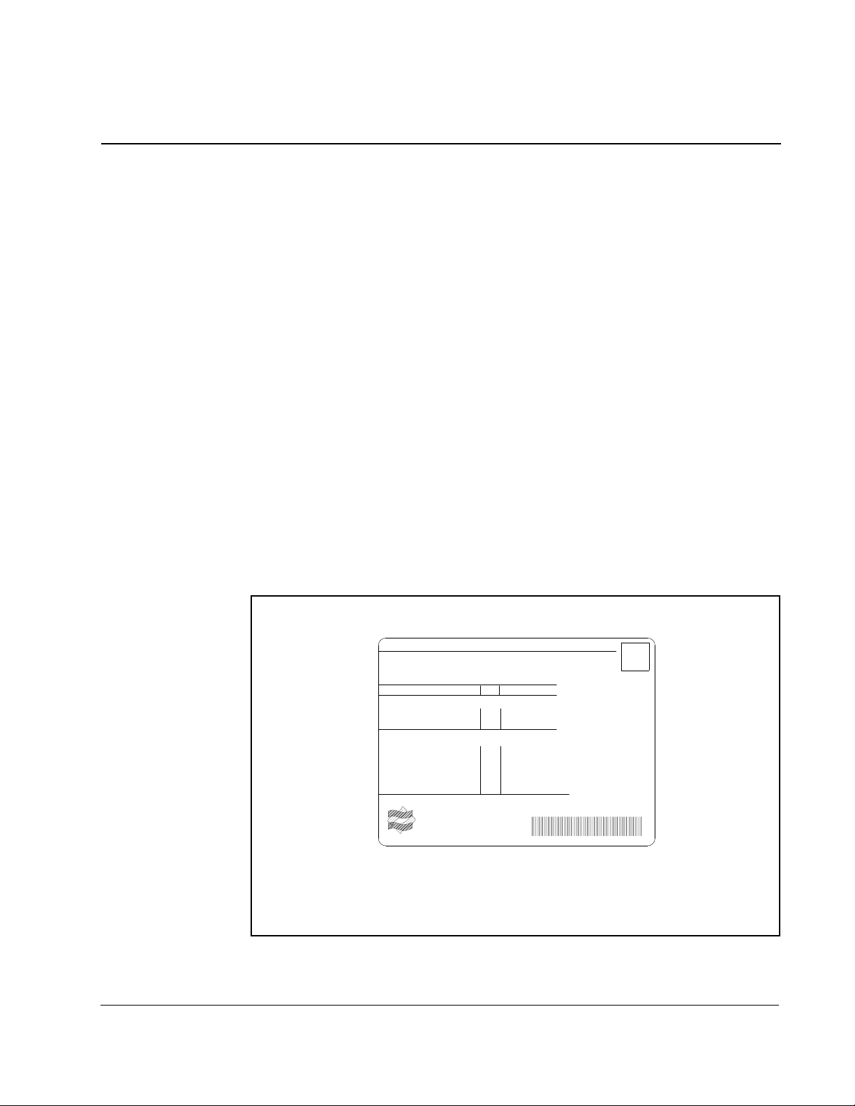
1.3 Identifying the Drive by Nameplate
Introduction
Introduction
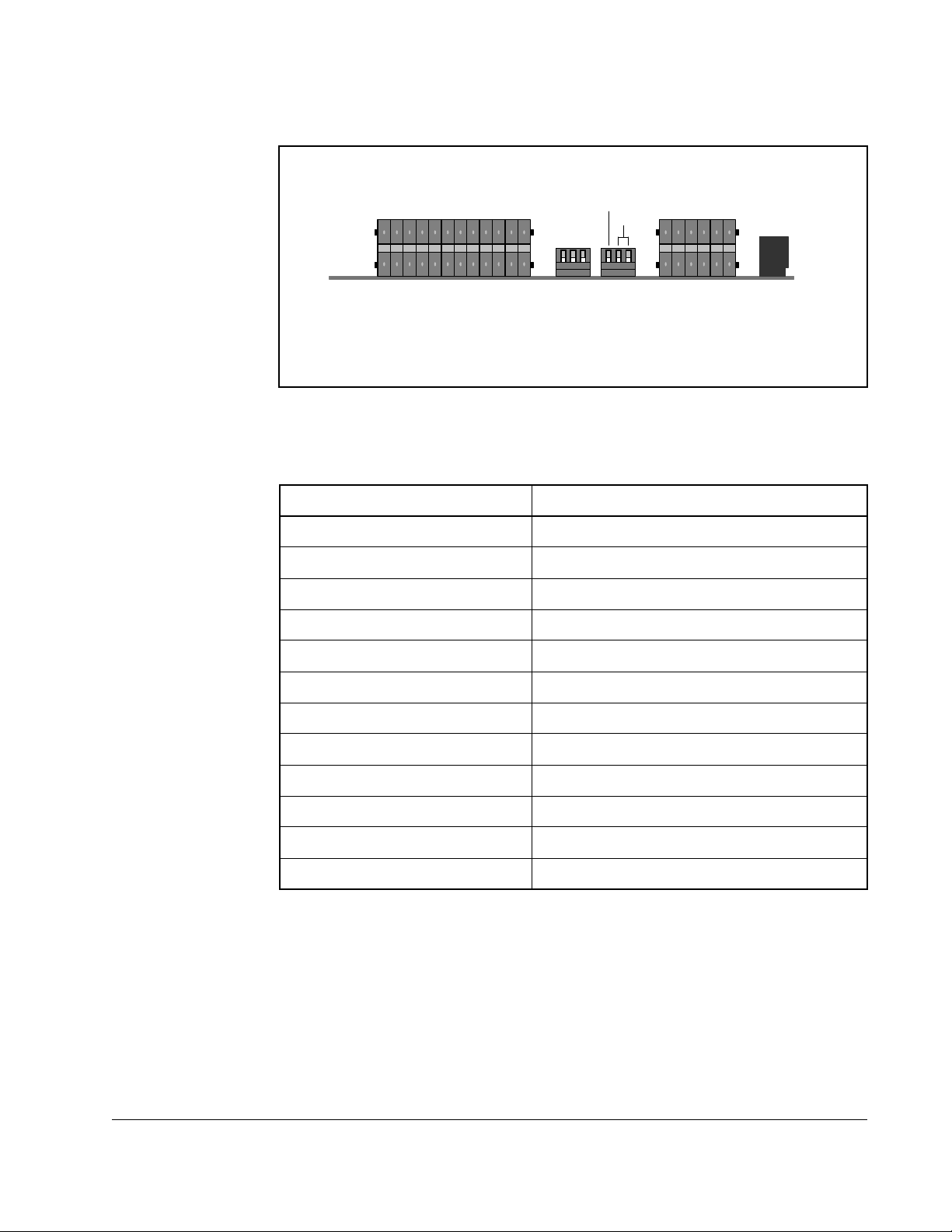
Each Reach Drive can be identified by its nameplate.
Figure 1.1 – Identifying the Drive by Nameplate
1-1
Page 6

1.4 Identifying the Drive by Model Number
Each Reach Drive and Reach Drive Kit can be identified by its model number. The
model number is on the shipping label and drive nameplate. The model number
includes the drive and any factory-installed options.
Table 1.1 – Reach Drive Model Numbers
Part Model Number
Reach Drive CNMD180W0ENNNC1
ControNet Comm
Adapter Fiber Kit
Pump Control
Adapter Kit
Dynamic Brake
Resistor Kit
CNM-CNETGF-11
CNM-PCTRL-11
CNM-R2-019P600
1-2
DBT Reach Drive User Manual
Page 7
Installation/Wiring
This chapter provides information on mounting and wiring the Reach Drive.
Most start-up difficulties are the result of incorrect wiring. Every precaution must be
taken to assure that the wiring is done as instructed. All items must be read and
understood before the actual installation begins
ATTENTION:The following information is merely a guide for proper
installation. Rockwell Automation cannot assume responsibility for the
!
2.1 AC Supply Source Considerations
Reach Drives are suitable for use on a circuit capable of delivering up to a maximum
of 200,000 rms symmetrical amperes and a maximum of 600 volts.
compliance or the noncompliance to any code, national, local or
otherwise for the proper installation of this drive or associated equipment.
A hazard of personal injury and/or equipment damage exists if codes are
ignored during installation.
CHAPTER 2
ATTENTION:To guard against personal injury and/or equipment
damage caused by improper fusing or circuit breaker selection, use only
!
If a system ground fault monitor (RCD) is to be used, only Type B (adjustable) devices
should be used to avoid nuisance tripping.
the recommended line fuses/circuit breakers specified in Appendix A.
Installation/Wiring
2-1
Page 8
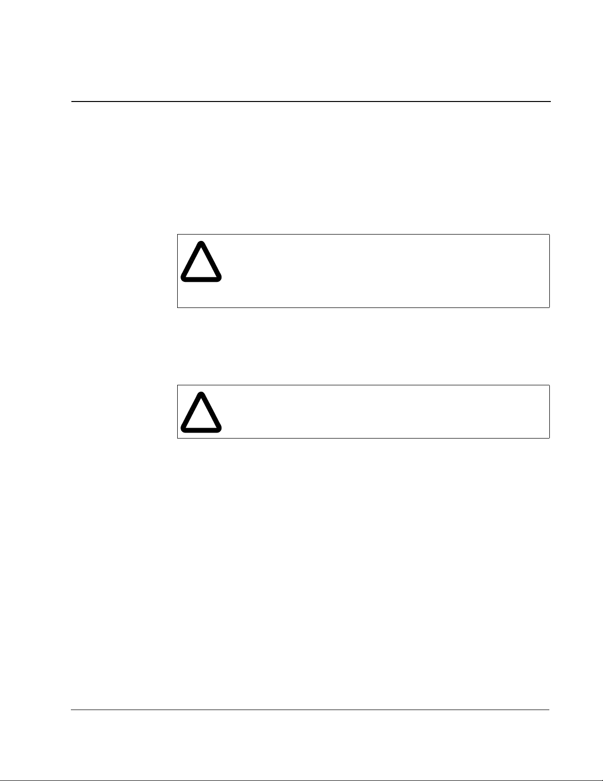
2.1.1 Unbalanced or Ungrounded Distribution Systems
ATTENTION:Power distribution to Reach Drives is intended to be from
the ungrounded secondary of the system’s step down transformer.
!
Protective MOVs, the EMI Snubber Board, and common mode capacitors
(3 places) in the drive have been disconnected. They should typically be
reconnected in any application where the power distribution at the drive
is grounded. Refer to Figure 2.1
STEP 1
SEE CONNECTION
DETAILS
STEP 2
CUT TY-WRAP
PULL INSULATED LEADS FREE
REMOVE INSULATED COVER
SEPARATE LEADS
2-2
REMOVE SCREW
FASTEN LUGS WITH SCREW TO FLANGE
TIGHTEN SCREW TO 28 in-lbs
TUCK LEADS BACK INTO UNIT
Figure 2.1 – Protective Circuit Connections for Grounded Drive Systems
2.1.2 Input Power Conditioning
Certain events on the power system supplying a drive can cause component damage
or shortened product life. The following events can cause such damage.
• The power system has power factor correction capacitors switched in and out of
the system, either by the user or by the power company.
• The power source has intermittent voltage spikes in excess of 6000 volts. These
spikes could be caused by other equipment on the line or by events such as
lightning strikes.
DBT Reach Drive User Manual
Page 9
• The power source has frequent interruptions.
GROUNDPOINT
GROUNDPOINT
GROUNDPOINT
If these conditions exist, it is recommended that the user install a minimum amount of
impedance between the drive and the source. This impedance could come from the
supply transformer itself, the cable between the transformer and drive or an additional
transformer or reactor.
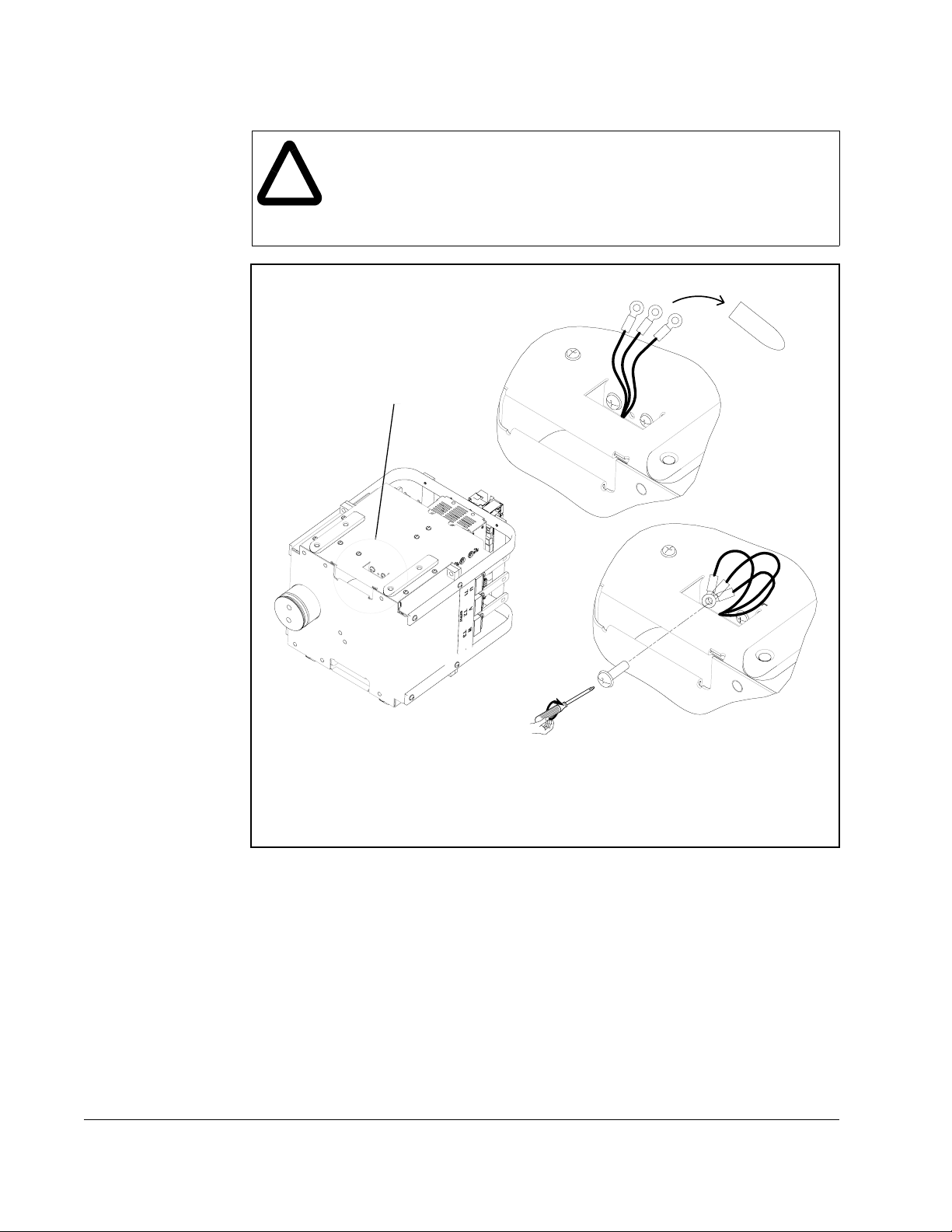
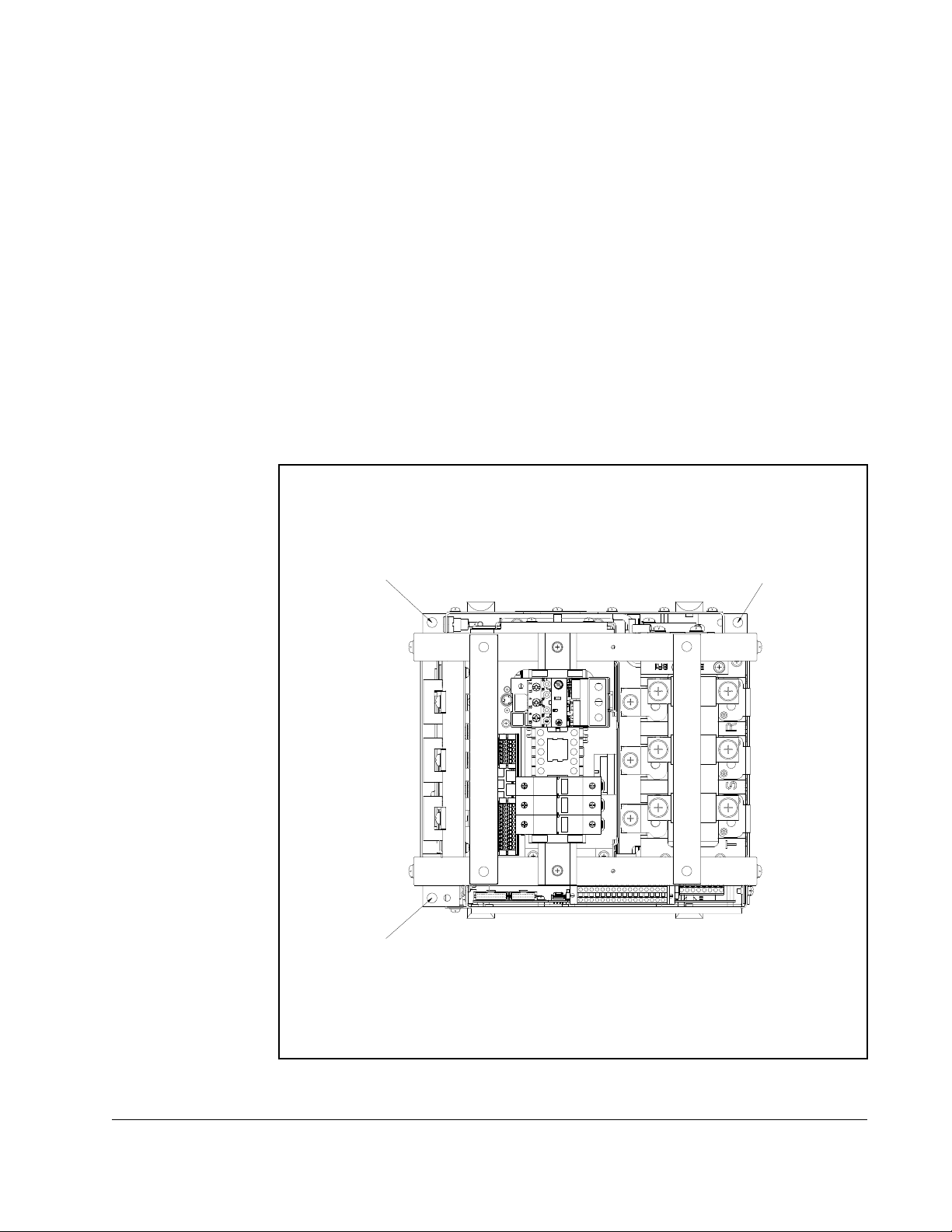
2.2 General Grounding Requirements
The drive Safety Ground - PE must be connected to system ground. Ground
impedance must conform to the requirements of national and local industrial safety
regulations and/or electrical codes. The integrity of all ground connections should be
periodically checked.
For installations within a cabinet, a single safety ground point or ground bus bar
connected directly to building steel should be used. All circuits including the AC input
ground conductor should be grounded independently and directly to this point/bar.
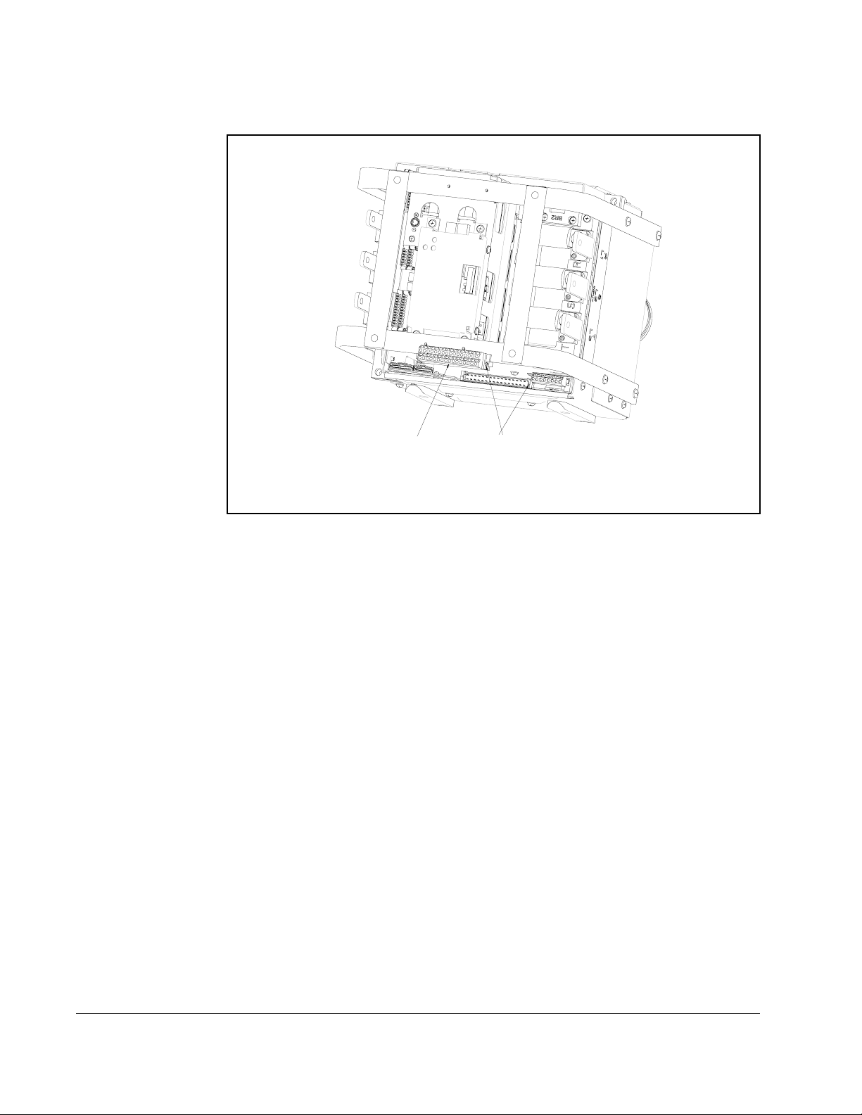
Refer to Figure 2.2 and Table 2.1.
Installation/Wiring
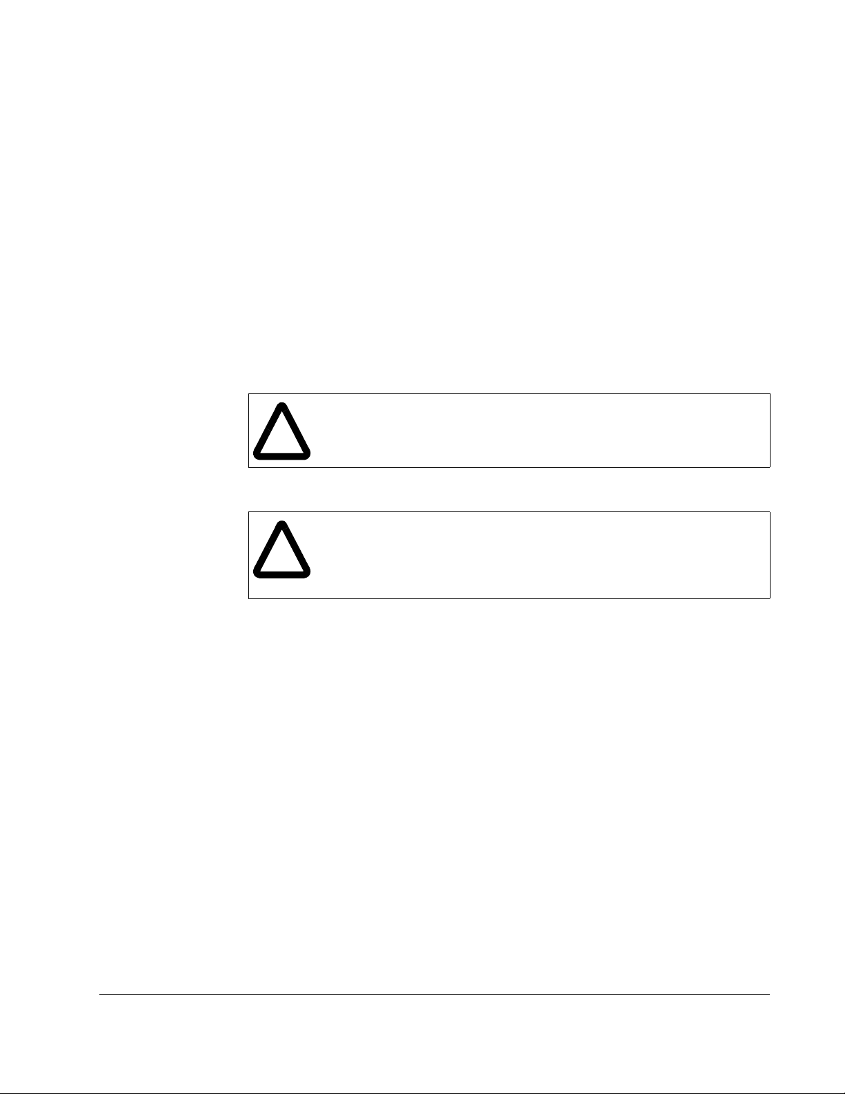
Figure 2.2 – Recommended Ground Locations
2-3
Page 10

Table 2.1 – Power Termination Locations Notes
Terminal Description Notes
BR1 DC Brake (+) DB Resistor Connection
BR2 DC Brake (-)
DC+ DC Bus (+)
DC- DC Bus (-)
PE PE Ground
Motor Ground
U U (T1) To motor
V V (T2) To motor
W W (T3) To motor
R R (L1) AC Line Input Power
S S (L2) AC Line Input Power
T T (L3) AC Line Input Power
PS+ AUX (+) Auxiliary Control Voltage
PS- AUX (-) Auxiliary Control Voltage
2.2.1 Safety Ground - PE
This is the safety ground for the drive that is required by code. This point must be
connected to adjacent building steel (girder, joist), a floor ground rod or bus bar (see
above). Grounding points must comply with national and local industrial safety
regulations and/or electrical codes.
2.2.2 Shield Termination - SHLD
The Shield terminal provides a grounding point for the motor cable shield. The motor
cable shield should be connected to this terminal on the drive (drive end) and the
motor frame (motor end). A shield terminating cable gland may also be used.
When shielded cable is used for control and signal wiring, the shield should be
grounded at the source end only, not at the drive end.
2-4
DBT Reach Drive User Manual
Page 11
2.2.3 RFI Filter Grounding
Using an optional RFI filter may result in relatively high ground leakage currents.
Therefore, the filter must only be used in installations with grounded AC supply
systems and be permanently installed and solidly grounded (bonded) to the
building power distribution ground. Ensure that the incoming supply neutral is solidly
connected (bonded) to the same building power distribution ground. Grounding must
not rely on flexible cables and should not include any form of plug or socket that would
permit inadvertent disconnection. Some local codes may require redundant ground
connections. The integrity of all connections should be periodically checked. Refer to
the instructions supplied with the filter.
2.3 Fuses and Circuit Breakers
The Reach Drive includes input fuses. National and local industrial safety regulations
and/or electrical codes may determine additional requirements for these installations.
Refer to Appendix A for recommended fuses/circuit breakers.
ATTENTION:The Reach Drive does not provide branch short circuit
protection. Specifications for the recommended fuse or circuit breaker to
!
provide protection against short circuits are provided in Appendix A.
2.4 Power Wiring
ATTENTION:National Codes and standards (NEC, VDE, BSI etc.) and
local codes outline provisions for safely installing electrical equipment.
!
Installation must comply with specifications regarding wire types,
conductor sizes, branch circuit protection and disconnect devices. Failure
to do so may result in personal injury and/or equipment damage.
2.4.1 Cable Types Acceptable for 200-600 Volt Installations
A variety of cable types are acceptable for drive installations. For many installations,
unshielded cable is adequate, provided it can be separated from sensitive circuits. As
an approximate guide, allow a spacing of 0.3 meters (1 foot) for every 10 meters (32.8
feet) of length. In all cases, long parallel runs must be avoided. Do not use cable with
an insulation thickness less than or equal to 15 mils (0.4mm/0.015 in.). Use Copper
wire only. Wire gauge requirements and recommendations are based on 75 degrees
C. Do not reduce wire gauge when using higher temperature wire.
Unshielded
THHN, THWN or similar wire is acceptable for drive installation in dry environments
provided adequate free air space and/or conduit fill rates limits are provided. Do not
use THHN or similarly coated wire in wet areas. Any wire chosen must have a
minimum insulation thickness of 15 Mils and should not have large variations in
insulation concentricity.
2.4.2 Motor Cable Lengths
Typically, motor lead lengths less than 91 meters (300 feet) are acceptable.
Installation/Wiring
2-5
Page 12
2.4.3 Power Termination Location Notes
BR1
BR2
(+) DC BUS
TEST POINT
(-) DC BUS
TEST POINT
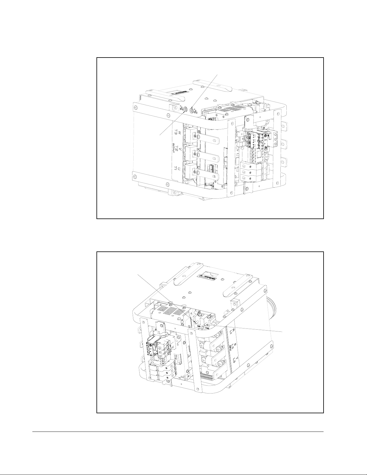
Figure 2.3 – Power Termination Locations (DC+ and DC-)
2-6
Figure 2.4 – Power Termination Locations (BR1 and BR2)
DBT Reach Drive User Manual
Page 13
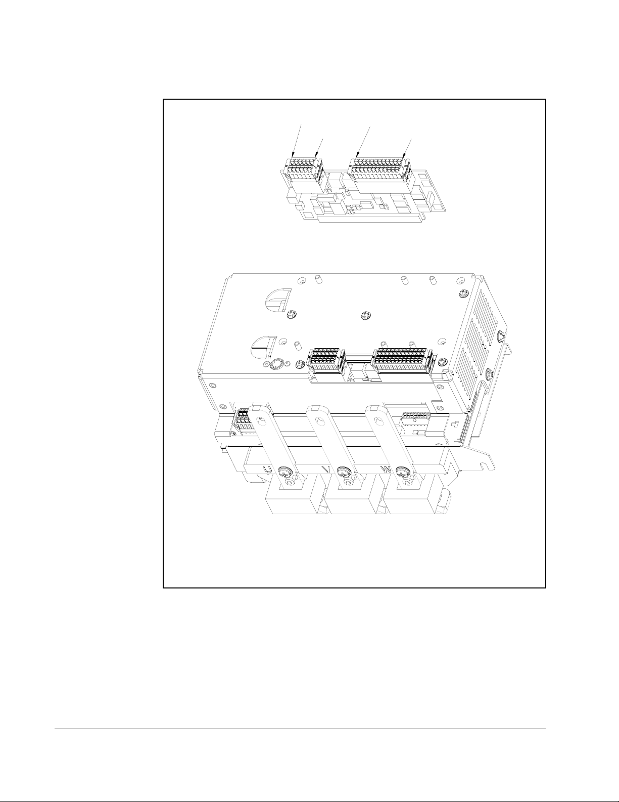
2.5 I/O Wiring
T
S
R
Important points to remember about I/O wiring:
• Use Copper wire only. Wire gauge requirements and recommendations are based
on 75 degrees C. Do not reduce wire gauge when using higher temperature wire.
• Wire with an insulation rating of 600V or greater is recommended.
• Control and signal wires should be separated from power wires by at least 0.3
meters (1 foot).
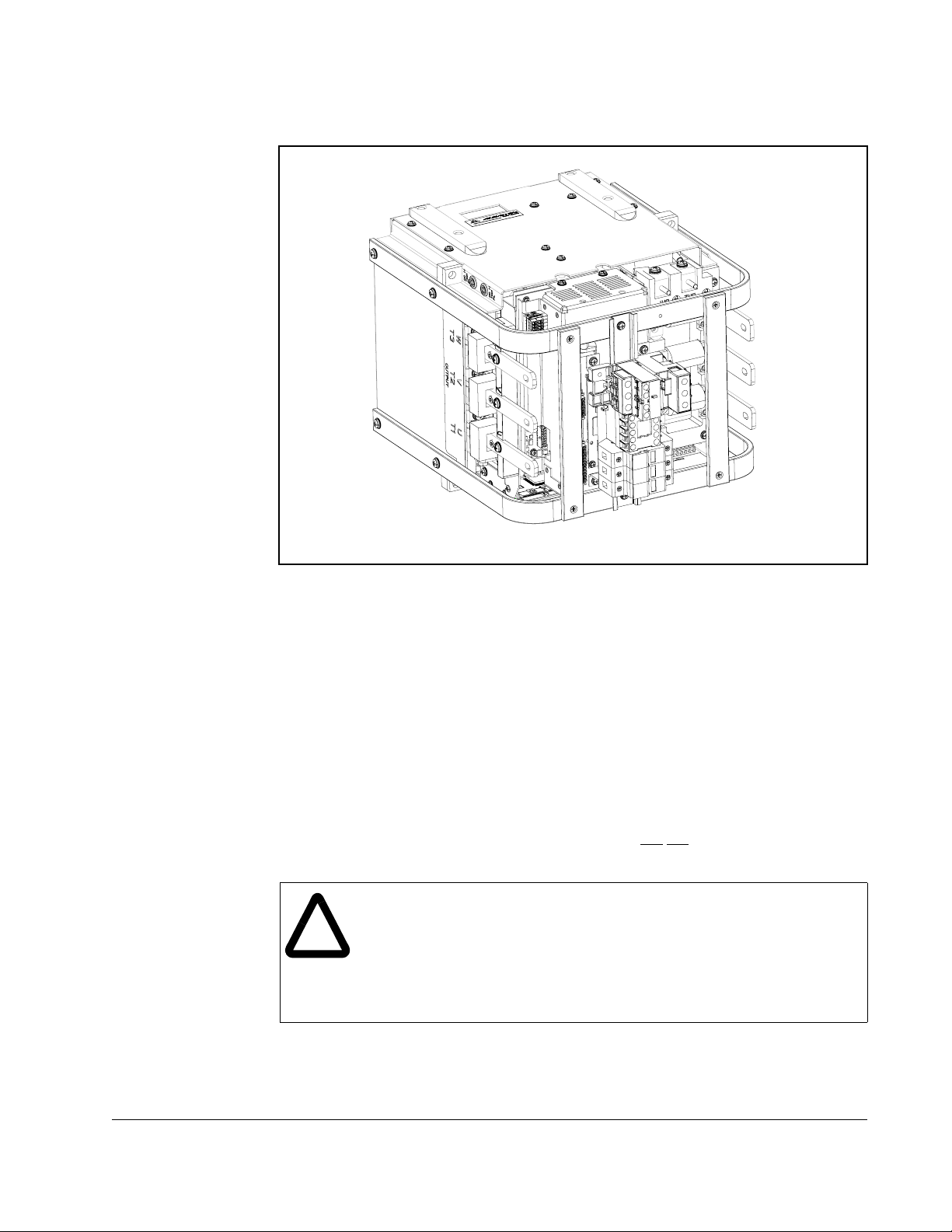
Figure 2.5 – Power Termination Locations (U, V, W, R, S, T)
Installation/Wiring
Important: I/O terminals labeled “(–)” or “Common” are
ground and are designed to greatly reduce common mode interference.
Grounding these terminals can cause signal noise.
ATTENTION:Configuring an analog input for 0-20mA operation and
driving it from a voltage source could cause component damage. Verify
!
proper configuration prior to applying input signals.
ATTENTION:Hazard of personal injury or equipment damage exists
when using bipolar input sources. Noise and drift in sensitive input circuits
can cause unpredictable changes in motor speed and direction. Use
speed command parameters to help reduce input source sensitivity.
not referenced to earth
2-7
Page 14
2.5.1 I/O Terminal Designations
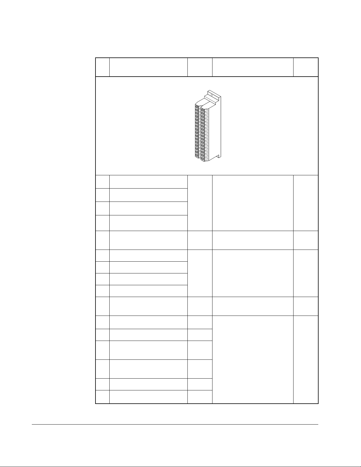
Table 2.2 – I/O Terminal Designations
No. Signal
1
Analog In 1 (-)
2
Analog In 1 (+)
3
Analog In 2 (-)
4
Analog In 2 (+)
12
1
1
1
Factory
Default Description
1
16
32
Isolated3, bipolar, differential
+/- 10V/4-20mA, 11 bit and
sign, 88k ohm input
impedance. For 4-20mA, a
jumper must be installed at
terminals 17 and 18 (or 19
and 20).
Rel.
Param.
320327
5 Port Common - For (+) and (-) 10V port
references.
6 Analog Out 1 (-)
2
Bipolar (current output is not
bipolar), +/- 10V/4-20mA, 11
7 Analog Out 1 (+)
8 Analog Out 2 (-)
bit and sign, voltage mode limit current to 5 mA. Current
mode - maxz load resistance
9 Analog Out 2 (+)
is 400 ohms.
10 HW PTC Input 1 - 1.8k ohm PTC, Internal 3.32k
ohm pull-up resistor
11
Digital Out 1 - N.C.
4
Fault Max. Resistive Load:
240V AC/30V DC -- 1200VA,
12 Digital Out 1 Common
13
Digital Out 1 - N.O.
14
Digital Out 2 - N.C.
4
4
NOT
Fault
NOT
Run
150W
Max. Current: 5A, Min. Load
10mA
Max. Inductive Load:
240V AC/30V DC - 840VA,
105W
15 Digital Out 2/3 Com
16
Digital Out 3 - N.O.
4
Run
Max. Current: 3.5A, Min.
Load: 10mA
340347
238
259
380391
2-8
DBT Reach Drive User Manual
Page 15

Table 2.2 – I/O Terminal Designations
Factory
No. Signal
17
Current In Jumper
In 1
18
19
Current In Jumper
Analog In 2
20
1
- Analog
1
–
Default Description
Placing a jumper across
terminals 17 and 18 (or 19
and 20) will configure that
analog input for current.
(Parameter 320 must be set
ON.)
21 –10V Pot Reference – 2k ohm minimum load.
22 +10V Pot Reference –
23 HW PTC Input 1 – See above
24
+24VDC
5
– Drive supplied logic input
power.
5
25 Digital In Common –
26
24V Common
(5)
– Common for internal power
supply.
27 Digital In 1 Stop - CF115V AC, 50/60 Hz
- Opto
isolated
Low State: less than 30V AC
28 Digital In 2 Start
29 Digital In 3 Auto/M
an.
30 Digital In 4 Speed
Sel 1
High State: greater than 100V
AC
24V DC
- Opto isolated
Low State: less than 5V DC
High State: greater than 20V
DC
11.2 mA DC
31 Digital In 5 Speed
Sel 2
Rel.
Param.
361366
Installation/Wiring
32 Digital In 6/Hardware Enable Speed
Sel 3
1.
Important: 4-20mA operation requires a jumper at terminals 17 and 18 (or 19 and 20). Drive damage may
occur if jumper is not installed.
2.
These inputs/outputs are dependant on a number of parameters (see “Rel. Param.).
3.
Differential Isolation - External source must be maintained at less than 160V with respect to PE. Input
provides high common mode immunity.
4.
Contacts in unpowered state. Any relay programmed as Fault or Alarm will energize (pick up) when power
is applied to drive and deengergize (drop out) when a fault or alarm exists. Relays selected for other
functions will energize only when that condition exists and will deenergize when condition is removed.
5.
150mA maximum load. Not present on 115V versions.
2-9
Page 16
32 POSITION I/O PLUG
REMOVE FROM CONTROL PCB
TERMINATE WIRE HARNESS TO PLUG
THEN MATE PLUG TO HEADER AND
FASTEN SCREWS TO 7 in-lbs
SCREW ON PLUG
NUT ON PCB HEADER
Figure 2.6 – I/O Plug
2-10
DBT Reach Drive User Manual
Page 17
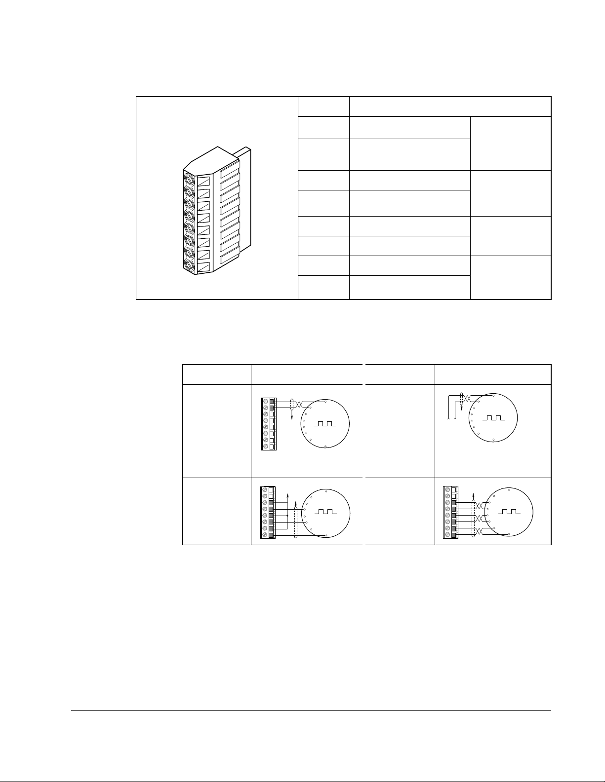
2.5.2 Encoder Terminal Block
Table 2.3 – Encoder Terminal Designations
No. Description
8
+12V
1
DC Power
7 +12V <Footnote>(1) DC
Return (Common)
8
6 Encoder Z (NOT) Pulse, marker or
5 Encoder Z
4 Encoder B (NOT) Quadrature B
3 Encoder B
1
2 Encoder A (NOT) Single channel
1 Encoder A
1.
Jumper selectable +5/12V is available on 20B-ENC-2 Encoder Boards only.
2.
Z channel can be used as a pulse input while A & B are used for encoder.
Table 2.4 – Sample Encoder Wiring
I/O Connection Example I/O Connection Example
Encoder
Power
1
–
Internal
Drive Power
Internal
+12V DC
(250 mA)
8
7
Common
6
5
to SHLD
4
3
2
1
Encoder
Power
–External
Power
Source
(drive) 12V
DC, 250mA
Internal power
source
250 mA.
registration
input.
input.
or quadrature A
input.
to
+
Common
SHLD
External
Power
Supply
2
Installation/Wiring
Encoder
Signal
–SingleEnded, Dual
Channel
1.
SHLD connection is on drive chassis.
to Power Supply
8
Common
7
6
5
4
3
2
1
Z NOT
Z
B NOT
B
A NOT
A
to SHLD
Encoder
Signal
–Differential,
Dual Channel
to SHLD
8
7
Z NOT
6
Z
5
B NOT
4
B
3
A NOT
2
A
1
2-11
Page 18

2.5.3 Signal and Control Wire Types
Table 2.5 – Recommended Signal Wire
Signal Type/
Where Used
B e l d e n W i r e T y p e ( s )
(or equivalent)
Description
Minimum
Insulation
Rating
Analog I/O
and PTC
Encoder/
Pulse I/O
<30 m (100
ft.)
Encoder/
Pulse I/O
30 to 152 m
(100 to 500
ft.)
Encoder/
Pulse I/O
152 to 259 m
(500 to 850
ft.)
8760/9460
8770
Combined:
Signal:
Power:
Combined:
Signal:
Power:
Combined:
2
9730
9730/9728
3
8790
4
9892
9730/9728
3
8790
9773/9774
2
0.750 mm
(18AWG),
twisted pair, 100% shield
with drain
0.750 mm
1
.
2
(18AWG), 3
cond., shielded for remote
pot only.
0.196 mm2(24AWG),
individually shielded.
2
0.196 mm2(24AWG),
individually shielded.
0.750 mm2(18 AWG)
0.330 mm2 or 0.500 mm2
4
2
0.196 mm2(24AWG),
individually shielded.
0.750 mm2(18 AWG)
5
0.750 mm2 (18 AWG) or
2
0.500 mm
, individually
shielded pair
300V,
75-90
degrees C
(167-194
degrees F)
2-12
1.
If the wires are short and contained within a cabinet which has no sensitive circuits, the use of shielded
wire may not be necessary, but is always recommended.
2.
9730 is 3 individually shielded pairs (2 channel + power). If 3 channel is required, use 9728.
3.
8790 is 1 shielded pair.
4.
9892 is 3 individually shielded pairs (3 channel), 0.332 (22 AWG) + 1 shielded pair 0.5 mm2 (20 AWG)
for power.
5.
9773 is 3 individually shielded pairs (2 channel + power). If channel 3 is required, use 9774.
DBT Reach Drive User Manual
Page 19

Table 2.6 – Recommended Control Wire for Digital I/O
Type Wire Type(s) Description
Minimum Insulation
Rating
Unshielded Per US NEC or applicable
national or local code
Shielded Multi-conductor shielded
cable such as Belden
8770(or equiv.)
– 300V,
60 degrees C
(140 degrees F)
0.750
2
(18AWG), 3
mm
conductor,
shielded.
Installation/Wiring
2-13
Page 20
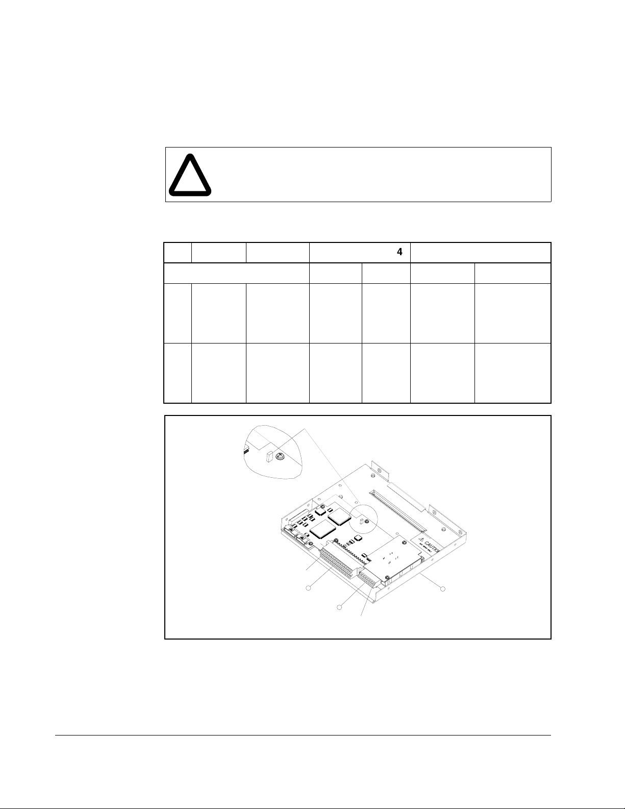
2.5.4 The I/O Control Board
4. Maximum/minimum sizes that the terminal block will accept - these are not recommendations.
4
Figure 2.2 shows the I/O control board and terminal block locations. The control board
provides a mounting point for the various Reach Drive I/O options. To remove the
cassette, loosen the two screw latches as shown in Figure 2.7. (A).
ATTENTION: You must stay within the minimum and maximum wire size
range. Failure to observe this precaution can result in severe equipment
!
damage, bodily injury, or loss of life.
2.5.5 I/O Terminal Blocks
No. Name Description Wire Size Range4 Torque
1
2
I/O
Terminal
Block
Encoder
Terminal
Block
Signal &
control
connections
Encoder
power &
signal
connections
Table 2.7 – I/O Terminal Block Specifications
Maximum Minimum Maximum Recommended
2.1 mm
2
(14 AWG)
0.30
mm
2
0.6 N-m
(5.2 lb.-in.)
(22
AWG)
0.75 mm
(18 AWG)
2
0.196
2
mm
0.6 N-m
(5.2 lb.-in.)
(24
AWG)
JUMPER
0.6 N-m
(5.2 lb.-in.)
0.6 N-m
(5.2 lb.-in.)
PIN 1
1
2
Figure 2.7 – Reach Drive Typical Control Board and I/O Terminal Blocks
2-14
A
PIN 1
DBT Reach Drive User Manual
Page 21

2.5.6 Hardware Enable Circuitry
By default, the user can program a digital input as an Enable input. The status of this
input is
disabled
can be utilized. This is done by removing a jumper and wiring the enable input to
“Digital In 6.” (See tables 2.5 and 2.6 for more information).
1. Remove the I/O Control board.
2. Locate and remove Jumper 10 on the Main Control Board (see Figure 2.7).
3. Re-assemble the I/O Control board.
4. Wire enable to Digital In 6.
5. Verify that Digital In6 Sel (366) is set to “1, Enable.”
interpreted by drive software
without
software interpretation, a “dedicated” hardware enable configuration
. If the application requires the drive to be
2.5.7 Resistance Temperature Detector (RTD) Board
Up to eight RTD or NTC (negative temperature coefficient) temperature sensors are
supported by the Reach Drive RTD board. The number of I/O required from an upper
level controller to utilize the RTD Board can be managed by selecting one of several
configuration options.
Installation/Wiring
2-15
Page 22
PIN 1
PIN 6
RTD PC BOARD
PIN 1
PIN 12
2-16
RTD PC BOARD ASSEMBLED IN ENCLOSURE
Figure 2.8 – RTD Board
DBT Reach Drive User Manual
Page 23
2.5.7.1 Connections
Gain
123
Mode
Time
123
24
13
112
712
16
S1 S2 J3 - I/OJ2 - RTD Inputs J2
Figure 2.9 – RTD Board Connections
Table 2.8 – J2 RTD Board I/O Function
Position I/O Function
1 +24V COM
2LOUT1 COM
3LOUT2 COM
4LOUT3 COM
5LIN COM
6AOUT COM
7 +24VDC
8LOUT1 NO
9LOUT2 NO
10 LOUT3 NO
11 LIN
12 AOUT
Important: A motor temperature sensor (RTD, NTC, or thermocouple) should be
2.5.7.2 Hardware
The hardware consists of a single PC board with two wired connectors, one for
temperature sensors and the second for power and I/O signals.
considered equivalent to a motor thermostat and wired with the same
considerations. Motor thermostat contacts are generally not isolated from
the drive/controller digital inputs. Therefore, the sensor inputs will not be
isolated on the RTD board.
Installation/Wiring
2-17
Page 24

RTD/NTC Sourcing
A 2-wire RTD or NTC temperature sensor may be used. A chassis connection is
available for each sensor for use with shielded cable. Each channel requires up to
three connections.
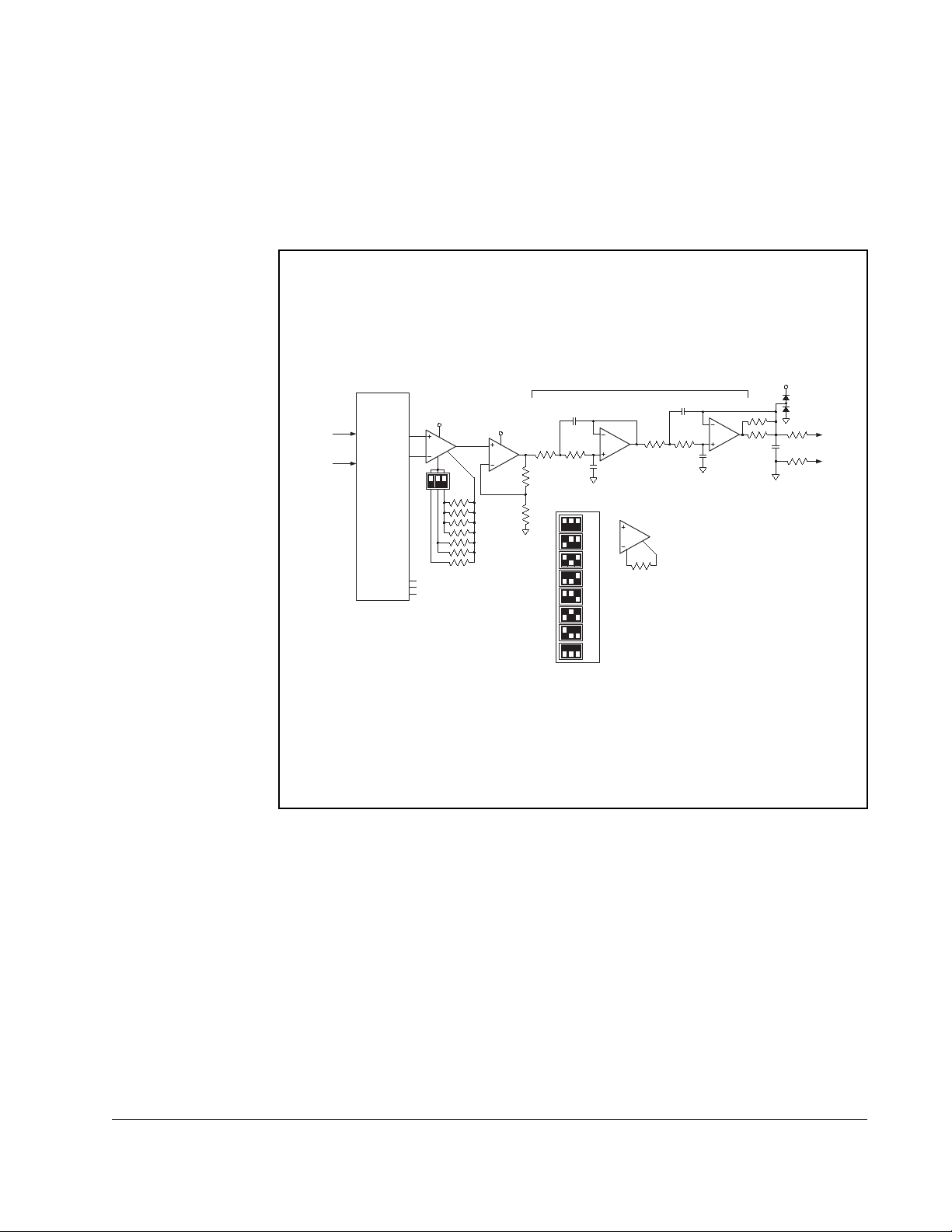
Multiplexer and Amplifier
An analog multiplexer sequentially connects the temperature sensors one at a time to
the analog output. The active sensor channel is indicated by a 3-bit output (A0-A2).
When using an RTD or NTC, a simple voltage divider is formed and the device is
probed differentially.
The sensor voltages are amplified using a high-quality, rail-to-rail instrumentation
amplifier with gain adjustment. To accomodate a variety of sensors and temperature
ranges, an amplifier boosts the analog sensor voltage in order to increase the
temperature resolution. Discrete gains of x10 through x80 are selectable through DIP
switch settings. A 4th order low pass filter rejects normal-mode noise at the analog
input with a cutoff frequency of approximately 16 Hz.
To determine the proper gain setting:
1. Determine R
, the maximum resistance of the sensor over the temperature
MAX
range to be measured.
2. Determine the maximum voltage across R
V
= 1.00V X
MAX
3. Select the largest gain that results in V
R
MAX
MAX
than 10 volts.
using the following equation:
MAX
/ (
R
+ 998)
MAX
* Gain (x10, x20, or x40), being less
2-18
DBT Reach Drive User Manual
Page 25
Example:
Using a 100 Ohm Pt RTD (a=0.00385) to measure temperatures from 0 degrees
Celsius to 200 degrees Celsius, the maximum resistance occurs at 200 degrees
Celsius and is approximately 177 Ohm. The maximum voltage across the sensor is
151 mV. If the x40 gain is used, the output voltage at 200 degrees Celsius is 6.04
Volts.
NTC/RTD
Sourcing
SA (1 of 8)
SB (1 of 8)
Analog Multiplexer
F
x10
x20
x30
x40
x50
x60
x70
x80
4th Order Low Pass Filter
MAX4194
Gain = 1 + 50K/Rg
Instrumentation Amp
Gain Adjustable
DA
DB
A0
Channel
A1
Address
A2
MAX4194
Rail-to-Rail
5V
S1
50K
12V
x10
100K
11.1K
F
100K 100K
Gain Adjust
DIP Switch Settings, S1
(overall gain)
up
down
Figure 2.10 – Scaled Analog Output for RTD Board
F
= 16Hz
C
100K 100K
LMC6484
Quad Op Amp
Rail-to-Rail
Rg
F
F
0.01 F
12V
10
Analog
Out
0-10V
10
Installation/Wiring
Digital I/O
The digital outputs are isolated with solid state relays. The outputs are internally short
circuit protected. The digital input is optically isolated.
2.5.7.3 Microcontroller Software
A microcontroller monitors three DIP switches to determine the operational mode of
the RTD board. A single “Mode” switch determines whether the board uses an internal
timebase or the digital input as a clock to step through the eight analog input
channels. When using the internal timebase, the other two DIP switches select one of
four clock periods.
2-19
Page 26

When the “Mode” switch is up (open) the board uses the digital input as an
enable/reset. When the board’s digital input is inactive (open or ground), the analog
output is held at the first channel. When the digital input is active (24V), the
microcontroller sequentially cycles through the eight temperature sensor channels.
Each channel is available at the analog output for the selected period of time. After the
eighth channel is completed, the cycle begins again with the first channel.
Deactivating the digital input will asynchronously reset the sequence back to the first
channel. The “Period” jumpers/dip switches select one of four time periods between
temperature sensor channels.
Table 2.9 – Microcontroller Settings
Period S2-2 S2-3
1 second Down Down
10 seconds Up Down
30 seconds Down Up
60 seconds Up Up
When the “Mode” switch (S2-1) is down (closed) the board uses the digital input as an
external clock to sequentially cycle through the eight temperature sensor channels.
The analog output channel advances with both the rising and falling edges of the
digital input. In both modes the active channel is output as a 3-bit binary address on
the RTD board’s digital outputs. An inactive output (open) indicates a “0.” When using
the digital input as an external clock, it may be necessary to monitor the address lines
in order to maintain synchronization with the controller. When using the internal clock
mode, the digital outputs may be ignored to reduce the required number of I/O. In
either mode, the board’s digital input is debounced with a period of 50mS.
2-20
DBT Reach Drive User Manual
Page 27
CHAPTER 3
Parameter Descriptions
The following information is provided for each parameter along with its description:
Parameter Number: Unique number assigned to each parameter.
Parameter Name: Unique name assigned to each parameter.
Range: Predefined parameter limits or selections. Note that a
negative Hz value indicates reverse rotation.
Default: Factory default setting.
Access: Parameter access level.
0 = Basic (reduced parameter set)
1 = Standard
2 = Advanced (full parameter set)
Path: Menu selections to reach specified parameter. The path is
indicated in this manner: File>Group
See also: Associated parameters that may provide additional or
related information.
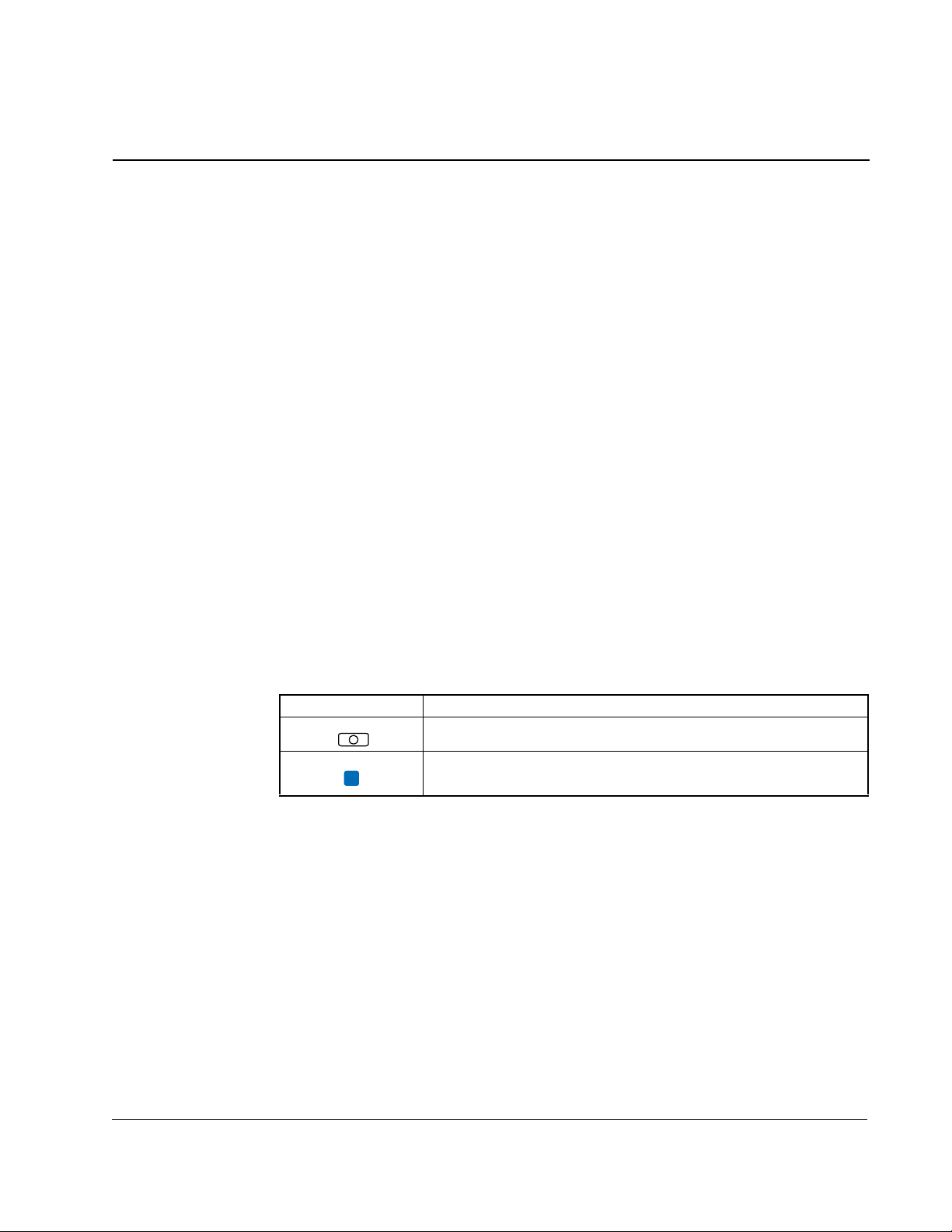
What the Symbols Mean
Symbol Meaning
Drive must be stopped before changing parameter value.
Parameter is only displayed when Motor Cntl Sel (53) is set to
FV
The parameters are presented in numerical order.
“4.” (FVC Vector)
Parameter Descriptions
3-1
Page 28

3.1 Parameters
1 Output Freq
Range: +/-400.0 Hz [0.1 Hz]
Default: Read Only
Access: 0 Path: Monitor>Metering
See also:
The output frequency present at T1, T2, and T3 (U, V, and W).
2 Commanded Speed
Range: +/- [P.082 Maximum Speed] [0.1 Hz or 0.1 RPM]
Default: Read Only
Access: 0 Path: Monitor>Metering
See also: 79
The value of the active Speed/Frequency Reference. Displayed in Hz or RPM,
depending on value of Speed Units (79).
3 Output Current
Range: 0.0 to Drive Rated Amps x 2 [0.1 A]
Default: Read Only
Access: 0 Path: Monitor>Metering
See also:
The total output current present at T1, T2, and T3 (U, V, and W).
4 Torque Current
Range: Drive Rating x -2/+2 [0.1 A]
Default: Read Only
Access: 1 Path: Monitor>Metering
See also:
The amount of current that is in phase with the fundamental voltage component.
5 Flux Current
Range: Drive Rating x -2/+2 [0.1 A]
Default: Read Only
Access: 1 Path: Monitor>Metering
See also:
3-2
The amount of current that is out of phase with the fundamental voltage component.
DBT Reach Drive User Manual
Page 29

6 Output Voltage
Range: 0.0 to Drive Rated Volts [0.1 VAC]
Default: Read Only
Access: 0 Path: Monitor>Metering
See also:
The output voltage present at terminals T1, T2, and T3 (U, V, and W).
7 Output Power
Range: 0 to Drive Rated kW x 2 [0.1 kW]
Default: Read Only
Access: 0 Path: Monitor>Metering
See also:
The output power present at T1, T2, and T3 (U, V, and W).
8 Output Powr Fctr
Range: 0.00 to 1.00 [0.01]
Default: Read Only
Access: 2 Path: Monitor>Metering
See also:
The output power factor.
9Elapsed MWh
Range: 0.0 to 214,748,352.0 MWh [0.1 MWh]
Default: Read Only
Access: 2 Path: Monitor>Metering
See also:
The accumulated output energy of the drive.
10 Elapsed Run Time
Range: 0.0 to 214,748,352.0 Hr [0.1 Hr]
Default: Read Only
Access: 1 Path: Monitor>Metering
See also:
The accumulated time the drive has been outputting power.
Parameter Descriptions
3-3
Page 30

11 MOP Reference
Range: +/- [Maximum Speed] [0.1 Hz or 0.1 RPM]
Default: Read Only
Access: 1 Path: Monitor>Metering
See also: 79
The value of the signal at the MOP (Motor-Operated Potentiometer).
12 DC Bus Voltage
Range: 0 to Based on Drive Rating [0.1 VDC]
Default: Read Only
Access: 1 Path: Monitor>Metering
See also:
The present DC bus voltage level.
13 DC Bus Memory
Range: 0 to Based on Drive Rating [0.1 VDC]
Default: Read Only
Access: 2 Path: Monitor>Metering
See also:
A six-minute average of the DC bus voltage level.
14 Elapsed kWh
Range: 0 to 429,496,729.5 kWh [0.1 kWh]
Default: Read Only
Access: 1 Path: Monitor>Metering
See also:
The accumulated output energy of the drive.
1617Analog In1 Value
Analog In2 Value
Range: 0.000 to 20.000 mA [0.001 mA]
-/+10.000 V [0.001 V]
Default: Read Only
Access: 1 Path: Monitor>Metering
See also:
The value of the signal of the analog input.
3-4
DBT Reach Drive User Manual
Page 31

18 PTC HW Value
Range: 0.00 to 5.00 Volts [0.01 Volts]
Default: Read Only
Access: 2 Path: Monitor>Metering
See also:
This parameter displays the value present at the drive’s PTC input terminals. When a
motor is provided with a PTC (positive temperature coefficient) thermal sensor, it can
be connected to terminals 10 and 23.
21 Spd Fdbk No Filt
Range:
Default: Read Only
Access: 2 Path: Monitor>Metering
See also:
Displays the unfiltered value of the actual motor speed based on either the measured
encoder feedback or on an estimation when an encoder is not present.
22 Ramped Speed
Range: +/- 400.0 Hz or +/- 24,000.0 RPM [0.1 Hz or 0.1 RPM]
Default: Read Only
Access: 1 Path: Monitor>Metering
See also: 79
The value of commanded speed after Accel/Decel and S-Curve are applied.
23 Speed Reference
Range: +/- 400.0 Hz or +/- 24,000.0 RPM [0.1 Hz or 0.1 RPM]
Default: Read Only
Access: 0 Path: Monitor>Metering
See also: 79
The summed value of ramped speed, process PI and droop. When FVC Vector mode
is selected, droop will not be added
Parameter Descriptions
3-5
Page 32

24 Commanded Torque
FV
Range: +/- 800.0% [0.1%]
Default: Read Only
Access: 0 Path: Monitor>Metering
See also: 53
The final torque reference value after limits and filtering are applied. Percent of motor
rated torque.
25 Speed Feedback
Range: +/- 400.0 Hz or +/- 24,000.0 RPM [0.1 Hz or 0.1 RPM]
Default: Read Only
Access: 1 Path: Monitor>Metering
See also:
Displays the lightly filtered value of the actual motor speed based on measured
encoder feedback or an estimation.
26 Rated kW
Range: 0.00 to 3000.00 kW [0.01 kW]
Default: Read Only
Access: 0 Path: Monitor>Drive Data
See also:
3-6
The drive power rating.
27 Rated Volts
Range: 0.0 to 65535.0 VAC [0.1 VAC]
Default: Read Only
Access: 0 Path: Monitor>Drive Data
See also:
The drive input voltage class (208, 240, 400, etc.).
28 Rated Amps
Range: 0.0 to 6553.5 Amps [0.1 Amps]
Default: Read Only
Access: 0 Path: Monitor>Drive Data
See also:
DBT Reach Drive User Manual
Page 33

The drive rated output current.
29 Control SW Ver
Range: 0.000 to 65535.000 [0.001]
Default: Read Only
Access: 0 Path: Monitor>Drive Data
See also: 196
The Main Control board software version.
40 Motor Type
Range: 0 = Induction
Default: 0 = Induction
Access: 2 Path: Motor Control>Motor Data
See also: 53, 157, 158, 159
Set to match the type of motor connected: Induction, Synchronous Reluctance, or
Synchronous Permanent Magnet.
Important: Selecting option 1 or 2 also requires selection of “Custom V/Hz,” option 2
1 = Synchr Reluc
2 = Synchr PM
in Motor Cntl Sel (53).
41 Motor NP Volts
Range: 0.0 to Drive Rated Volts [0.1 VAC]
Default: Based on Drive Rating
Access: 1 Path: Motor Control>Motor Data
See also:
Set to the motor nameplate rated volts. The motor nameplate base voltage defines the
output voltage when operating at rated current, rated speed, and rated temperature.
42 Motor NP FLA
Range: 0.0 to Rated Amps x 2 [0.1 Amps]
Default: Based on Drive Rating
Access: 1 Path: Motor Control>Motor Data
See also: 47, 48
Set to the motor nameplate rated full load amps. The motor nameplate FLA defines
the output amps when operating at rated voltage, rated speed, and rated temperature.
It is used in the motor thermal overload and in the calculation of slip.
Parameter Descriptions
3-7
Page 34

43 Motor NP Hertz
Range: 5.0 to 400.0 Hz [0.1 Hz]
Default: Based on Drive Type
Access: 1 Path: Motor Control>Motor Data
See also:
Set to the motor nameplate rated frequency. The motor nameplate base frequency
defines the output frequency when operating at rated voltage, rated current, rated
speed, and rated temperature.
44 Motor NP RPM
Range: 60.0 to 25200.0 RPM [0.1 RPM]
Default: 1780 RPM
Access: 1 Path: Motor Control>Motor Data
See also:
Set to the motor nameplate rated RPM. The motor nameplate RPM defines the rated
speed when operating at motor nameplate base frequency, rated current, base
voltage, and rated temperature. This is used to calculate slip.
45 Motor NP Power
Range: 0.00 to 1000.00 [0.01 kW or 0.01 HP]
Default: Based on Drive Type
Access: 1 Path: Motor Control>Motor Data
See also: 46
3-8
Set to the motor nameplate rated power. The motor nameplate power is used with the
other nameplate values to calculate default values for motor parameters to assist the
commissioning process. This may be entered in horsepower or in kilowatts as
selected in Mtr NP Pwr Units (46).
46 Mtr NP Pwr Units
Range: 0 = Horsepower (changes power units to HP without rescaling values)
1 = kilowatts (changes power units to kW without rescaling values)
2 = Convert HP (Converts all power units to HP and rescales values)
3 = Convert kW (changes power units to kW and rescales values)
Default: Based on Drive Rating
Access: 2 Path: Motor Control>Motor Data
See also:
Selects the motor power units to be used. This parameter determines the units for
Motor NP Power (45).
Convert HP = Converts all power units to Horsepower.
Convert kW = Converts all power units to kilowatts.
DBT Reach Drive User Manual
Page 35

47 Motor OL Hertz
Range: 0.0 to Motor NP Hz [0.1 Hz]
Default: Motor NP Hz/3
Access: 2 Path: Motor Control>Motor Data
See also: 42, 220
Selects the output frequency below which the motor operating current is derated. The
motor thermal overload will then generate a fault at lower levels of current.
48 Motor OL Factor
Range: 0.20 to 2.00 [0.1]
Default: 1.00
Access: 2 Path: Motor Control>Motor Data
See also: 42, 220
Sets the amps threshold for motor overload fault.
Motor FLA x OL Factor = Operating Level
49 Motor Poles
Range: 2 to 40 [1 Pole]
Default: 4
Access: 0 Path: Motor Control>Motor Data
See also:
Defines the number of poles in the motor.
53 Motor Cntl Sel
Range: 0 = Sensrls Vect
Default: 0 = Sensrls Vect
Access: 2 Path: Motor Control>Torq Attributes
See also: 80
Sets the method of motor control used in the drive.
Important: “FVC Vector” mode with encoder feedback requires autotuning of the
Sensrls Vect = Maintains consistent magnetizing current up to base speed. Voltage
increases as a function of load.
1 = SV Economize
2 = Custom V/Hz
3 = Fan/Pmp-V/Hz
4 = FVC Vector
motor, both coupled and uncoupled to the load. Being coupled to the load
will determine inertia (preferably lightly loaded). Total Inertia (450) will
have to be estimated if uncoupled for tuning of the speed loop or
separately adjust Ki (445) and Kp (446).
Parameter Descriptions
3-9
Page 36

SV Economize = Allows the drive to automatically adjust output voltage as the load
changes to minimize current supplied to the motor. The voltage is adjusted by means
of flux current adaptation.
Custom V/Hz = Allows the user to tailor the volts/hertz curve by adjusting parameters
Maximum Voltage (54), Maximum Frequency (55), Run Boost (70), Break Voltage (71)
and Break Frequency (72).
Fan/Pmp V/Hz = This mode sets a fan load volts/hertz curve profile exponential to
base frequency (and linear from base to maximum frequency). Run Boost (70) can
offset the low speed curve point.
FVC Vector = This mode requires autotuning of the motor, both coupled and
uncoupled to the load.
54 Maximum Voltage
Range: (Rated Volts x 0.25) to Rated Volts [0.1 VAC]
Default: Drive Rated Volts
Access: 2 Path: Motor Control>Torq Attributes
See also:
Sets the highest voltage the drive will output.
55 Maximum Freq
Range: 5.0 to 420.0 Hz [0.1 Hz]
Default: 110.0 or 130.0 Hz
Access: 2 Path: Motor Control>Torq Attributes
See also: 83
Sets the maximum allowable frequency the drive will output. Note that this is not
maximum speed, which is set in parameter 82. Refer to figure 3.1.
ATTENTION: The user is responsible for ensuring that the driven
machinery, all drive-train mechanisms, and application material are
!
capable of safe operation at the maximum operating speed of the drive.
Overspeed detection in the drive determines when the drive shuts down.
The factory default for overspeed detection is set to 10.0 Hz (or 300.0
RPM) greater than the Maximum Speed (82). Failure to observe this
precaution could result in equipment damage, sever injury or loss of life.
3-10
DBT Reach Drive User Manual
Page 37

Allowable Output Frequency Range -
Bus Regulation or Current Limit
V
Max Volts
o
(54)
l
t
Motor Volts
a
(41)
g
e
Break Volts
(71)
Start Boost
(69)
Run
Boost
(70)
0 Break
56 Compensation
Range: See figure 3.2
Default: See figure 3.2
Access: 2 Path: Motor Control>Torq Attributes
See also:
Allowable Output Frequency Range - Normal Operation
Allowable Speed Reference Range
Frequency Trim
due to Speed
Control Mode
Min
Speed
(81)
Frequency
(72)
Motor NP Hz
(43)
Frequency
Figure 3.1 – Speed Limits
Overspeed
Max
Speed
(82)
Limit
(83)
Output
Freq Limit
Maximum
Freq
(55)
Parameter Descriptions
Enables/disables the compensation correction options.
(1)
ave
x
Rs Adapt
Mtr Lead Rev
Xsistor Diag
Ixo AutoCalc
101110
Enable Jerk
Reflect W
1
0
x =Reserved
=Enabled
=Disabled
10 01234567891112131415
Bit #
Factory Default Bit Values
PWM FreqLock
TPEncdless
0
0
xxxxxxx
(1)
For current limit (except FVC Vector mode).
Figure 3.2 – Compensation (56)
Reflect Wave = Enables/disables reflected wave correction software, which reduces
overvoltage transients from the drive to the motor. For lead lengths beyond 300 feet,
enable this feature.
3-11
Page 38

Enable Jerk = Enables/disables the jerk limit in the current limiter that helps to
eliminate overcurrent trips on fast accelerations. Disable this feature if your application
requires the actual acceleration of the motor to be faster than .25 sec. In non-FVC
Vector modes, disabling jerk removes a short S-curve at the start of the accel/decel
ramp.
Ixo AutoCalc = Reserved
Xsistor Diag = Enables/disables power transistor power diagnostic tests that execute
at each Start command.
Rs Adapt = (FVC w/Encoder only) Disabling may improve torque regulation at lower
speeds (although this is typically not needed).
Mtr Lead Rev = Reverses the phase rotation of the applied voltage, effectively
reversing the motor leads.
PWM Freq Lock = Keeps the PWM frequency from decreasing to 2 kHz at low
operating frequencies in FVC Vector mode without encoder.
57 Flux Up Mode
Range: 0 = Manual
1 = Automatic
Default: 0 = Manual
Access: 2 Path: Motor Control>Torq Attributes
See also: 53, 58
Manual (0): Flux is established for Flux Up Time (58) before acceleration
Auto (1): Flux is established for a calculated time period based on motor nameplate
data. Flux Up Time (58) is not used.
58 Flux Up Time
Range: 0.000 to 5.000 sec [0.001 sec]
Default: 0.000 sec
Access: 2 Path: Motor Control>Torq Attributes
See also: 53, 58
Sets the amount of time the drive will use to try to achieve full motor stator flux. When
a start command is issued, DC current at current limit level is used to build stator flux
before accelerating.
59 SV Boost Filter
Range: 0 to 32767 [1]
Default: 500
Access: 0 Path: Motor Control>Torq Attributes
See also:
Sets the amount of filtering used to boost voltage during Sensorless Vector and FVC
Vector (encoderless) operation.
3-12
DBT Reach Drive User Manual
Page 39

61 Autotune
Range: 0 = Ready
Default: 3 = Calculate
Access: 1 Path: Motor Control>Torq Attributes
See also: 53, 62
Provides a manual or automatic method for setting IR Voltage Drop (62), Flux Current
Ref (63) and Ixo Voltage Drop (64). Valid only when Motor Cntl Sel (53) is set to
Sensrls Vect, SV Economize or FVC Vector.
Ready (0) = Parameter returns to this setting following a Static Tune or Rotate Tune. It
also permits manually setting IR Voltage Drop (62), Ixo Voltage Drop (64) and Flux
Current Ref (63).
Static Tune (1) = A temporary command that initiates a non-rotational motor stator
resistance test for the best possible automatic setting of IR Voltage Drop (62) in all
valid modes and a non-rotational motor leakage inductance test for the best possible
automatic setting of Ixo Voltage Drop (64) in FVC Vector Mode. A start command is
required following the initiation of this setting. The parameter returns to Ready (0)
following the test, at which time another start transition is required to operate the drive
in normal mode. Used when the motor cannot be rotated.
1 = Static Tune
2 = Rotate Tune
3 = Calculate
Rotate Tune (2) = A temporary command that initiates a Static Tune followed by a
rotational test for the best possible automatic setting of Flux Current Ref (63). In FVC
Vector mode, with encoder feedback, a test for the best possible automatic setting of
Slip RPM @ FLA is also run. A start command is required following initiation of this
setting. The parameter returns to Ready (0) following the test, at which time another
start transition is required to operate the drive in normal mode.
Important: Rotate Tune (2) is used when the motor is uncoupled from the load.
Results may not be valid if a load is coupled to the motor during this
!
Calculate (3) = This setting uses motor nameplate data to automatically set IR
Voltage Drop (62), Ixo Voltage (64) and Flux Current Ref (63).
procedure.
ATTENTION:Rotation of the motor in an undesired direction can occur
during this procedure (Autotune (61) = Rotate Tune (2)). To guard against
possible injury and/or equipment damage, it is recommended that the
motor be disconnected from the load before proceeding.
Parameter Descriptions
3-13
Page 40

62 IR Voltage Drop
Range: 0.0 to Motor NP Volts x 0.25 [0.1 VAC]
Default: Based on Drive Rating
Access: 1 Path: Motor Control>Torq Attributes
See also: 53, 61
Value of volts dropped across the resistance of the motor stator. Used only when
Motor Cntl Sel (53) is set to Sensrls Vect, SV Economize or FVC Vector.
63 Flux Current Ref
Range: 0.00 to Motor NP FLA [0.01 Amps]
Default: Based on Drive Rating
Access: 1 Path: Motor Control>Torq Attributes
See also: 53, 61
Value of amps for full motor flux. Used only when Motor Cntl Sel (53) is set to Sensrls
Vect, SV Economize or FVC Vector.
64 Ixo Voltage Drop
Range: 0.00 to 230.0, 460.0 or 575.0 VAC [0.1 VAC]
Default: Based on Drive Rating
Access: 1 Path: Motor Control>Torq Attributes
See also:
Sets the value of the voltage drop across the leakage inductance of the motor at rated
motor current. Used only when Motor Cntl Sel (53) is set to Sensrls Vect, SV
Economize or FVC Vector.
66 Autotune Torque
Range: 0.0 to 150% [0.1%]
FV
Default: 50%
Access: 1 Path: Motor Control>Torq Attributes
See also: 53
Specifies motor torque applied to the motor during the flux current and inertia tests
performed during an autotune.
3-14
DBT Reach Drive User Manual
Page 41

67 Inertia Autotune
FV
Range: 0 = Ready
Default: 0 = Ready
Access: 1 Path: Motor Control>Torq Attributes
See also: 53, 450
Provides an automatic method of setting Total Inertia. This test is automatically run
during Start-Up motor tests.
Important: Use when motor is coupled to the load. Results may not be valid if the
Ready = Parameter returns to this setting following a completed inertia tune.
Inertia Tune = A temporary command that initiates an inertia test of the motor/load
combination. The motor will ramp up and down, while the drive measures the amount
of inertia.
1 = Inertia Tune
load is not coupled to the motor during this procedure.
69 Start/Acc Boost
Range: 0.0 to Motor NP Volts x 0.25 [0.1 VAC]
Default: Based on drive rating
Access: 2 Path: Motor Control>Volts per Hertz
See also: 53, 70
Sets the voltage boost level for starting and acceleration when Custom V/Hz mode is
selected.
70 Run Boost
Range: 0.0 to Motor NP Volts x 0.25 [0.1 VAC]
Default: Based on drive rating
Access: 2 Path: Motor Control>Volts per Hertz
See also: 53, 69,
Sets the boost level for steady state or deceleration when Fan/Pmp V/Hz or Custom
V/Hz modes are selected.
71 Break Voltage
Range: 0.0 to Motor NP Volts [0.1 VAC]
Default: Motor NP Volts x 0.25
Access: 2 Path: Motor Control>Volts per Hertz
See also: 53, 72
Sets the voltage the drive will output at Break Frequency (72).
Parameter Descriptions
3-15
Page 42

72 Break Frequency
Range: 0.0 to Maximum Freq [0.1 Hz]
Default: Motor NP Freq x 0.25
Access: 2 Path: Motor Control>Volts per Hertz
See also: 53, 71
Sets the frequency the drive will output at Break Voltage (71).
79 Speed Units
Range: 0 = Hz
1 = RPM
2 = Convert Hz
3 = Convert RPM
Default: 0 = Hz
Access: 0 Path: Speed Command>Spd Mode & Limits
See also:
Selects the units to be used for all speed related parameters. Options 0 and 1 indicate
status only. Options 2 and 3 will convert and/or configure the drive for that selection.
Convert Hz (2) = Converts all speed based parameters to Hz and changes the value
proportionately (i.e. 1800 RPM = 60 Hz).
Convert RPM (3) = Converts all speed based parameters to RPM and changes the
value proportionately.
80 Feedback Select
Range: 0 = Open Loop
Default: 0 = Open Loop
Access: 2 Path: Speed Command>Spd Mode & Limits
See also: 53, 152, 412
Selects the source for motor speed feedback. Note that all selections are available
when using Process PI.
1 = Slip Comp
2 = Reserved
3 = Encoder
4 = Reserved
5 = Simulator
3-16
DBT Reach Drive User Manual
Page 43

ATTENTION: When operating the drive with encoder feedback selected
(Feedback Select (80) = 3 (Encoder)), a loss of encoder signal may
!
Open Loop (0) = Provides no speed compensation due to load variations. This is
strict volts per hertz output as a function of the speed reference. Slip compensation is
not needed and encoder is not present.
Slip Comp (1) = Provides for frequency output adjustment as a function of load. The
amount of compensation is defined by the value of Slip RPM @ FLA (121). It is used
when tight speed control is needed and an encoder is not present.
Encoder (3) = An encoder is present and connected to the drive.
Simulator (5) = Simulates a motor for testing drive operation and interface check.
produce an overspeed condition. For differential encoders, Motor Fdbk
Type (412) should be selected as option 1 or 3 to detect the loss of an
encoder signal. The user is responsible for ensuring that the driven
machinery, all drive-train mechanisms, and application material are
capable of safe operation at the maximum operating speed of the drive.
Overspeed detection in the drive determines when the drive shuts down.
The factory default for overspeed detection is set to 10.0 Hz (or 300.0
RPM) greater than the Maximum Speed (82). Failure to observe this
precaution could result in equipment damage, sever injury or loss of life.
81 Minimum Speed
Range: 0.0 to Maximum Speed [0.1 Hz or 0.1 RPM]
Default: 0.0
Access: 0 Path: Speed Command>Spd Mode & Limits
See also: 79, 83, 92, 95
Sets the low limit for the speed reference after scaling is applied.
ATTENTION:The drive can operate at and maintain zero speed. The
user is responsible for assuring safe conditions for operating personnel
!
by providing suitable guards, audible or visual alarms, or other devices
to indicate that the drive is operating or may operate at or near zero
speed. Failure to observe this precaution could result in severe bodily
injury or loss of life.
82 Maximum Speed
Range: 5.0 to 400.0 [0.1 Hz] or 75.0 to 24000.0 RPM [0.1 RPM]
Default: 50.0 or 60.0 Hz (Volt Class) [Motor NP RPM]
Access: 0 Path: Speed Command>Spd Mode & Limits
See also: 55, 79, 83, 91, 94, 202
Sets the high limit for the speed reference after scaling is applied.
Parameter Descriptions
3-17
Page 44

ATTENTION: The user is responsible for ensuring that the driven
machinery, all drive-train mechanisms, and application material are
!
capable of safe operation at the maximum operating speed of the drive.
Overspeed detection in the drive determines when the drive shuts down.
The factory default for overspeed detection is set to 10.0 Hz (or 300.0
RPM) greater than the Maximum Speed (82). Failure to observe this
precaution could result in equipment damage, sever injury or loss of life.
83 Overspeed Limit
Range: 0.0 to 20.0 Hz [0.1 Hz] or 0.0 to 600.0 RPM [0.1 RPM]
Default: 10.0 Hz or 300.0 RPM
Access: 2 Path: Speed Command>Spd Mode & Limits
See also: 55, 79, 82
Sets the incremental amount of the output frequency (above Maximum Speed)
allowable for functions such as slip compensation. See figure 3.3.
Maximum Speed + Overspeed Limit must be ≤ to Maximum Frequency
ATTENTION: The user is responsible for ensuring that the driven
machinery, all drive-train mechanisms, and application material are
!
capable of safe operation at the maximum operating speed of the drive.
Overspeed detection in the drive determines when the drive shuts down.
The factory default for overspeed detection is set to 10.0 Hz (or 300.0
RPM) greater than the Maximum Speed (82). Failure to observe this
precaution could result in equipment damage, sever injury or loss of life.
3-18
V
Max Volts
o
l
t
Motor Volts
a
g
e
Break Volts
Start Boost
(54)
(41)
(71)
(69)
Run
Boost
(70)
0 Break
Speed
Allowable Output Frequency Range -
Bus Regulation or Current Limit
Allowable Output Frequency Range - Normal Operation
Allowable Speed Reference Range
Frequency Trim
due to Speed
Control Mode
Min
(81)
Frequency
(72)
Figure 3.3 – Speed Limits
Motor NP Hz
(43)
Frequency
Overspeed
Limit
(83)
Max
Speed
(82)
Output
Freq Limit
DBT Reach Drive User Manual
Maximum
Freq
(55)
Page 45

84
85
86
Skip Frequency 1
Skip Frequency 2
Skip Frequency 3
Range: -/+ Maximum Speed [0.1 Hz]
Default: 0.0 Hz
Access: 2 Path: Speed Command>Spd Mode & Limits
See also: 87
Sets a frequency at which the drive will not operate (also called an avoidance
frequency). Requires that both Skip Frequency 1-3 and Skip Frequency Band (87) be
set to a value other than 0.
87 Skip Freq Band
Range: 0.0 to 30.0 Hz [0.1 Hz]
Default: 0.0 Hz
Access: 2 Path: Speed Command>Spd Mode & Limits
See also: 84, 85, 86
Determines the bandwidth around a skip frequency (half the band above and half the
band below the skip frequency). The same bandwidth applies to all skip frequencies.
88 Speed/Torque Mod
Range: 0 = Zero Torque
1 = Speed Reg
FV
Default: 1 = Speed Reg
Access: 1 Path: Speed Command>Spd Mode & Limits
See also: 53
!
Selects the torque reference source.
2 = Torque Reg
3 = Min Torq/Spd
4 = Max Torq/Spd
5 = Sum Torq/Spd
6 = Absolute Min
7 = Pos/Spd Prof
ATTENTION: When selecting operation in a torque mode configuration,
the user is responsible for ensuring that the driven machinery, all
drive-train mechanisms, and application material are capable of safe
operation at the maximum operating speed of the drive. Overspeed
detection in the drive determines when the drive shuts down. The factory
default for overspeed detection is set to 10.0 Hz (or 300.0 RPM) greater
than the Maximum Speed (82). Failure to observe this precaution could
result in equipment damage, sever injury or loss of life.
Parameter Descriptions
Zero Torque (0) = Torque Command = 0.
3-19
Page 46

Speed Reg (1) = Drive operates as a speed regulator.
Torque Reg (2) = An external torque reference is used for the torque command.
Min Torq/Spd (3) = Selects the smallest algebraic value to regulate to when the
torque reference and torque generated from the speed regulator are compared.
Max Torq/Spd (4) = Selects the largest algebraic value to regulate to when the torque
reference and torque generated from the speed regulator are compared.
Sum Torq /Spd (5) = Selects the sum of the torque reference and the torque
generated from the speed regulator.
Absolute Min (6) = Selects the smallest absolute algebraic value to regulate to when
the torque reference and torque generated from the speed regulator are compared.
Pos/Spd Prof (7) = Drive operates as a speed or position regulator as determined by
the steps configured by the Profile Step parameters (720-877) and Setup parameters
(705-719).
89 Logic Source Sel
Range: 0 = Terminal Blk
Default: 1 = Local HIM
Access: 0 Path: Speed Command>Control Src Sel
See also:
1 = Local HIM
2 = DPI Port 2
3 = DPI Port 3
4 = Reserved
5 = Network
6 = Reserved
7 = All Ports
3-20
Selects the only control source for these logic commands:
• Start (Run)
• Jog
• Direction
• Clear Faults
• Stop (Any attached HIM Stop Key is always functional. A Network stop command is
effective only for Network or All Ports. A Terminal Block Stop command is effective
only for Terminal Blk or All Ports.
Selecting All Ports (7) enables control from any control source (or port).
DBT Reach Drive User Manual
Page 47

ATTENTION: Changing parameter 89 to Terminal Blk or Network
while Start At PowerUp is enabled may start the drive if a start
!
Important: Asserting an HIM Control digital input or acquiring Manual with Save HIM
command is on from the newly selected logic source.
When Start At PowerUp is enabled, the user must ensure that
automatic start up of the driven equipment will not cause injury to
operating personnel or damage to the driven equipment. In addition,
the user is responsible for providing suitable audible or visual alarms or
other devices to indicate that this function is enabled and the drive may
start at any moment. Failure to observe this precaution could result in
severe bodily injury or loss of life.
ATTENTION: Removing and replacing the LCD HIM while the drive is
running may cause an abrupt speed change if the LCD HIM is the
selected reference source, but is not the selected control source. The
drive will ramp to the reference level provided by the HIM at the rate
specified in Accel Time 1 (140), Accel Time 2 (141), Decel Time 1
(142) and Decel Time 2 (143). Be aware that an abrupt speed change
may occur depending upon the new reference level and the rate
specified in these parameters. Failure to observe this precaution could
result in bodily injury.
Ref (192) bit 1 (Manual Mode) True (1) will override this parameter’s
selection.
90 Speed Ref A Sel
Range: 1 = Analog In 1
Default: 18 = Local HIM
Access: 0 Path: Speed Command>Speed References
See also: 2, 91-93, 101-107, 117-120, 192-194, 213, 272, 273, 320, 361-366
2 = Analog In 2
3-6 = Reserved
7 = Pulse In
8 = Encoder
9 = MOP Level
10 = Reserved
11 = Preset Spd 1
12 = Preset Spd 2
13 = Preset Spd 3
14 = Preset Spd 4
15 = Preset Spd 5
16 = Preset Spd 6
17 = Preset Spd 7
18 = Local HIM
19 = DPI Port 2
20 = DPI Port 3
21 = DPI Port 4
22 = Network
23-24 = Reserved
25 = Scale Block 1
26 = Scale Block 2
27 = Scale Block 3
28 = Scale Block 4
Speed Command>Control Src Select
Parameter Descriptions
3-21
Page 48

Selects the source of the speed reference to the drive unless Preset Speed 1-7
(101-107)
Note that the manual reference command and input HIM Control can override the
reference control source.
or Speed Ref B (93) is selected.
ATTENTION:Removing and replacing the LCD HIM while the drive is
running may cause an abrupt speed change if the LCD HIM is the
!
selected reference source. The drive will ramp to the reference level
provided by the HIM at the rate specified in Accel Time 1 (140), Accel
Time 2 (141), Decel Time 1 (142) and Decel Time 2 (143). Be aware that
an abrupt speed change may occur depending upon the new reference
level and the rate specified in these parameters. Failure to observe this
precaution could result in bodily injury.
91 Speed Ref A Hi
Range: -/+Maximum Speed [0.1 Hz or 0.1 RPM]
Default: Maximum Speed
Access: 1 Path: Speed Command>Speed References
See also: 79, 82, 190
Scales the upper value of the Speed Ref A Sel (90) selection when the source is an
analog input.
92 Speed Ref A Lo
Range: -/+Maximum Speed [0.1 Hz or 0.01 RPM]
Default: 0.0
Access: 1 Path: Speed Command>Speed References
See also: 79, 81, 190
Scales the lower value of the Speed Ref A Sel (90) selection when the source is an
analog input.
3-22
DBT Reach Drive User Manual
Page 49

93 Speed Ref B Sel
Range: 1 = Analog In 1
2 = Analog In 2
3-6 = Reserved
7 = Pulse In
8 = Encoder
9 = MOP Level
10 = Reserved
11 = Preset Spd 1
12 = Preset Spd 2
13 = Preset Spd 3
14 = Preset Spd 4
15 = Preset Spd 5
16 = Preset Spd 6
17 = Preset Spd 7
18 = Local HIM
19 = DPI Port 2
20 = DPI Port 3
21 = DPI Port 4
22 = Network
23-24 = Reserved
25 = Scale Block 1
26 = Scale Block 2
27 = Scale Block 3
28 = Scale Block 4
Default: 11 = Preset Spd 1
Access: 0 Path: Speed Command>Speed References
Speed Command> Control Src Select
See also: 2, 91-93, 101-107, 117-120, 192-194, 213, 272, 273, 361-366
Selects the source of the speed reference to the drive unless Preset Speed 1-7
(101-107)
Note that the manual reference command and input HIM Control can override the
reference control source.
!
is selected.
ATTENTION:Removing and replacing the LCD HIM while the drive is
running may cause an abrupt speed change if the LCD HIM is the
selected reference source. The drive will ramp to the reference level
provided by the HIM at the rate specified in Accel Time 1 (140), Accel
Time 2 (141), Decel Time 1 (142) and Decel Time 2 (143). Be aware that
an abrupt speed change may occur depending upon the new reference
level and the rate specified in these parameters. Failure to observe this
precaution could result in bodily injury.
Parameter Descriptions
3-23
Page 50

94 Speed Ref B Hi
Range: -/+Maximum Speed [0.1 Hz or 0.01 RPM]
Default: Maximum Speed
Access: 1 Path: Speed Command>Speed References
See also: 79, 93, 190
Scales the upper value of the Speed Ref B Sel (93) selection when the source is an
analog input.
95 Speed Ref B Lo
Range: -/+Maximum Speed [0.1 Hz or 0.01 RPM]
Default: 0.0
Access: 1 Path: Speed Command>Speed References
See also: 79, 90, 93, 190
Scales the lower value of the Speed Ref B Sel (93) selection when the source is an
analog input.
96 TB Man Ref Sel
Range: 1 = Analog In 1
2 = Analog In 2
3-8 = Reserved
9 = MOP Level
3-24
Default: 2 = Analog In 2
Access: 1 Path: Speed Command>Speed References
See also: 97, 98
Specifies the manual speed reference source when a digital input is configured for
auto/manual.
Important: Analog ln 2 is not a valid selection if it was selected for Trim ln Select
(117), PI Feedback Sel (128), PI Reference Sel (126), Current Lmt Sel
(147) or Sleep Wake Ref (179).
97 TB Man Ref Hi
Range: -/+Maximum Speed [0.1 Hz or 0.01 RPM]
Default: Maximum Speed
Access: 1 Path: Speed Command>Speed References
See also: 79, 96
Scales the upper value of the TB Man Ref Sel selection when the source is an analog
input.
DBT Reach Drive User Manual
Page 51

98 TB Man Ref Lo
Range: -/+Maximum Speed [0.1 Hz or 0.01 RPM]
Default: 0.0
Access: 1 Path: Speed Command>Speed References
See also: 79, 96
Scales the lower value of the TB Man Ref Sel selection when the source is an analog
input.
99 Pulse Input Ref
Range: -/+ 400.0 Hz or -/+ 24000.0RPM [0.1 Hz or 0.1 RPM]
Default: Read Only
Access: 0 Path: Speed Command>Speed References
See also:
Displays the pulse input value as seen at terminals 5 and 6 of the Encoder Terminal
Block if Encoder Z Chan (423) is set to “Pulse Input.”
100 Jog Speed 1
Range: +/- Maximum Speed [0.1 Hz or 0.1 RPM]
101
102
103
104
105
106
107
Default: 10.0 Hz or 300.0 RPM
Access: 0 Path: Speed Command>Discrete Speeds
See also: 79
Sets the output frequency/speed when a jog command is issued. Units are selected
by Speed Units (79).
Preset Speed 1
Preset Speed 2
Preset Speed 3
Preset Speed 4
Preset Speed 5
Preset Speed 6
Preset Speed 7
Range: -/+Maximum Speed [0.1 Hz or 1 RPM]
Default: See table 3.1
Access: See table 3.1 Path: Speed Command>Discrete Speeds
See also: 79, 90, 93
Provides an internal fixed speed command value. In bipolar mode, direction is
commanded by the sign of the reference.
Parameter Descriptions
3-25
Page 52

Parameter No. Parameter Name Default Access
101 Preset Speed 1 5.0 Hz or 150 RPM 0
102 Preset Speed 2 10.0 Hz or 300 RPM 2
103 Preset Speed 3 20.0 Hz or 600 RPM 2
104 Preset Speed 4 30.0 Hz or 900 RPM 2
105 Preset Speed 5 40.0 Hz or 1200 RPM 2
106 Preset Speed 6 50.0 Hz or 1500 RPM 2
107 Preset Speed 7 60.0 Hz or 1800 RPM 2
108 Jog Speed 2
Range: -/+ Maximum Speed [0.1 Hz or 0.1 RPM]
Default: 10.0 Hz or 300.0 RPM
Access: 0 Path: Speed Command>Discrete Speeds
See also:
Sets the output frequency of the drive when Jog Speed 2 is selected.
116 Trim % Setpoint
Range: -/+ 200.0% [0.1 %]
Default: 0.0%
Access: 2 Path: Speed Command>Speed Trim
See also: 118
Table 3.1 – Default Values for Preset Speeds 1-7
3-26
Adds or subtracts a percentage of the speed reference or maximum speed.
Dependent on the setting of Trim Out Select (118).
DBT Reach Drive User Manual
Page 53

117 Trim In Select
Range: 0 = Setpoint
1 = Analog In 1
2 = Analog In 2
3-6 = Reserved
7 = Pulse In
8 = Encoder
9 = MOP Level
10 = Reserved
11 = Preset Spd 1
12 = Preset Spd 2
13 = Preset Spd 3
14 = Preset Spd 4
15 = Preset Spd 5
16 = Preset Spd 6
17 = Preset Spd 7
18 = Local HIM
19 = DPI Port 2
20 = DPI Port 3
21 = DPI Port 4
22 = Network
23-24 = Reserved
25 = Scale Block 1
26 = Scale Block 2
27 = Scale Block 3
28 = Scale Block 4
Default: 1 = Analog In 1
Access: 2 Path: Speed Command>Speed Trim
See also: 90, 93
Specifies which input signal is being used as a trim input. The trim is an input signal
that is added to the selected speed reference. If an analog input is used as the trim
signal, two scaling parameters [Trim Hi (119) and Trim Lo (120)] are provided.
118 Trim Out Select
Range: See figure 3.4
Default: See figure 3.4
Access: 2 Path: Speed Command>Speed Trim
See also: 117, 119, 120
Specifies which speed references are to be trimmed.
Parameter Descriptions
3-27
Page 54

119 Trim Hi
Range: -/+Maximum Speed [0.1 Hz or 1 RPM/%]
Default: 60.0 Hz
Access: 2 Path: Speed Command>Speed Trim
See also: 79, 82, 117
Scales the upper value of the Trim In Select (117) selection when the source is an
analog input.
120 Trim Lo
Range: -/+Maximum Speed [0.1 Hz] or 1 RPM/%]
Default: 0.0 Hz
Access: 2 Path: Speed Command>Speed Trim
See also: 79, 117
Bit #
PTC HW
0
Reserved
x
AutoRst Act
DB Active
AutoRst Ctdn
Curr Limit
Motor Overld
Bus Freq Reg
DPI at 500 k
10 01234567891112131415
Figure 3.4 – Trim Out Select (118)
AutoTuning
Stopping
DC Braking
Jogging
Active
Running
00000000000000
Ready
1
=Condition True
0
=Condition False
x =Reserved
3-28
Scales the lower value of the Trim In Select (117) selection when the source is an
analog input.
Important: Parameters 121, 122, and 123 are used to enable and tune the Slip
Compensation Regulator. In order to allow the regulator to control drive
operation, Feedback Select (80) must be set to 1 = Slip Comp.
121 Slip RPM @ FLA
Range: 0.0 to 1200.0 RPM [0.1 RPM]
Default: Based on Motor NP RPM
Access: 2 Path: Speed Command>Slip Comp
See also: 61, 80, 122, 123
Sets the amount of compensation to drive output at motor FLA. If Autotune (61) is set
to 3 = Calculate, changes made to this parameter will not be accepted.
Value may be changed by Autotune (61) when “Encoder” is selected in Feedback
Select (80).
DBT Reach Drive User Manual
Page 55

122 Slip Comp Gain
Range: 1.0 to 100.0 [0.1]
Default: 40.0
Access: 2 Path: Speed Command>Slip Comp
See also: 80, 121, 122
Sets the response time of slip compensation.
123 Slip RPM Meter
Range: -/+300.0 RPM [0.1 RPM]
Default: Read Only
Access: 2 Path: Speed Command>Slip Comp
See also: 80, 121, 122
Displays the present amount of adjustment being applied as slip compensation.
Important: Parameters in the Process PI Group are used to enable and tune the PI
Loop. In order to allow the PI Loop to control drive operation, set PI
Control (125) to Enabled, bit 0 = 1.
124 PI Configuration
Range: See figure 3.5
Default: See figure 3.5
Access: 2 Path: Speed Command>Process PI
See also: 124-138
Selects specific features of the PI regulator.
ind Up
Preload Mode
Zero Clamp
Feedbak Sqrt
x
xxxxx
10 01234567891112131415
Bit #
Factory Default Bit Values
Figure 3.5 – PI Configuration (124)
Torque Trim
% of Ref
Anti-W
Stop Mode
Ramp Ref
Bit 0 - Excl Mode (Exclusive Mode)
• Enabled = Selects speed regulation.
• Disabled = Selects trim regulation.
Invert Error
0000000000
Excl Mode
1
=Enabled
0
=Disabled
x =Reserved
Parameter Descriptions
3-29
Page 56

Bit 1 - Invert Error
• Enables/disables the option to invert the sign of the PI error signal. Enabling this
feature creates a decrease in output for an increasing error and an increase in
output for a decreasing error.
Bit 2 - Preload Mode
• Enabled = Initializes the PI integrator to the commanded speed while the PI is
disabled.
• Disabled = The PI integrator is loaded with the PI Pre-load (133) while the PI is
disabled.
Bit 3 - Ramp Ref
• Enables/disables ramping the reference used from PI Feedback to the selected PI
Reference after PI is enabled. The active accel time is used for the PI ramp
reference slew rate. The ramping is bypassed when the reference equals the
setpoint.
Bit 4 - Zero Clamp
• Enables/disables option to limit operation so that the output frequency always has
the same sign as the master speed reference. This limits the possible drive action to
one direction only. Output from the drive will be from zero to maximum frequency
forward or zero to maximum frequency reverse.
Bit 5 - Feedback Sqrt (Square Root Feedback)
• Enables/disables the option of using the square root of the feedback signal as the PI
feedback. This is used for pressure control because fans and pumps vary pressure
with the square of the speed.
Bit 6 - Stop Mode
• Enabled = A Stop command is issued to the drive and the PI Loop will continue to
operate during the decel ramp.
Bit 7 - Anti-Windup
Enabled = The PI Loop will automatically prevent the integrator from creating an
excessive error that could cause instability. The integrator will be controlled without the
need for PI Reset or PI Hold Inputs.
Bit 8 - Torque Trim
• PI Output summed into the Torque Input.
Bit 9 - % of Ref
• PI scaled to % of Ref instead of Max Frequency.
125 PI Control
Range: See figure 3.6
Default: See figure 3.6
Access: 2 Path: Speed Command>Process PI
See also: 124-138
Controls the PI regulator. Note that you must use a datalink to write to this parameter
interactively from a network.
3-30
DBT Reach Drive User Manual
Page 57

PI control allows the drive to take a reference signal (setpoint) and an actual signal
(feedback) and automatically adjust the speed of the drive to match the actual signal
to the reference.
Proportional control (P) adjusts the output based on the size of the error (larger error =
proportionally larger correction).
Integral control (I) adjusts the output based on the duration of the error. The integral
control by itself is a ramp output correction. This type of control gives a smoothing
effect to the output and will continue to integrate until zero error is achieved.
By itself, integral control is slower than many applications require, and, therefore, is
combined with proportional control (PI).
The purpose of the PI regulator is to regulate a process variable such as position,
pressure, temperature, or flow rate, by controlling speed.
There are two ways the PI regulator can be configured to operate (see parameter
124):
• Process trim, which takes the output of the PI regulator and sums it with a master
speed reference to control the process.
• Process control, which takes the output of the PI regulator as the speed command.
No master speed reference exists, and the PI output directly controls the drive
output.
Note that Feedback Select (80) must be set to Process PI (2).
PI Hold
PI Enable
PI Reset
00
x0xxxxxxxxxxxx
10 01234567891112131415
Nibble 1Nibble 2Nibble 3Nibble 4
1
=Enabled
0
=Disabled
x =Reserved
Bit #
Factory Default Bit Values
Figure 3.6 – PI Control (125)
Bit 0 - PI Enable
• Enables/disables the operation of the PI loop.
Note: To use the PI loop, Bit 0 must be set to Enable (1), even if a digital input has
been programmed to be used as a PI Enable (See parameters 361-366).
Bit 1 - PI Hold
• Enabled = The integrator for the outer control loop is held at the current level; that
is, it will not increase.
• Disabled = The integrator for the outer PI control loop is allowed to increase.
Bit 2 - PI Reset
• Enabled = The integrator for the outer PI control loop is reset to zero.
• Disabled = The integrator for the outer PI control loop integrates normally.
Parameter Descriptions
3-31
Page 58

126 PI Reference Sel
Range: 0 = Setpoint
1 = Analog In 1
2 = Analog In 2
3-6 = Reserved
7 = Pulse In
8 = Encoder
9 = MOP Level
10 = Master Ref
11 = Preset Spd 1
12 = Preset Spd 2
13 = Preset Spd 3
14 = Preset Spd 4
15 = Preset Spd 5
16 = Preset Spd 6
17 = Preset Spd 7
18 = Local HIM
19 = DPI Port 2
20 = DPI Port 3
21 = DPI Port 4
22 = Network
23-24 = Reserved
25 = Scale Block 1
26 = Scale Block 2
27 = Scale Block 3
28 = Scale Block 4
Default: 0 = PI Setpoint
Access: 2 Path: Speed Command>Process PI
See also: 124-138
Selects the source of the PI reference signal. Setting this parameter to 0 = PI Setpoint
indicates PI Setpoint (127) is used.
127 PI Setpoint
Range: -/+100.00% of Maximum Process Value [0.01%]
Default: 50.00%
Access: 2 Path: Speed Command>Process PI
See also: 124-138
Provides an internal fixed value for the process setpoint when PI Reference Sel (126)
is set to PI Setpoint.
3-32
DBT Reach Drive User Manual
Page 59

128 PI Feedback Sel
Range: 0 = Setpoint
1 = Analog In 1
2 = Analog In 2
3-6 = Reserved
7 = Pulse In
8 = Encoder
9 = MOP Level
10 = Master Ref
11 = Preset Spd 1
12 = Preset Spd 2
13 = Preset Spd 3
14 = Preset Spd 4
15 = Preset Spd 5
16 = Preset Spd 6
17 = Preset Spd 7
18 = Local HIM
19 = DPI Port 2
20 = DPI Port 3
21 = DPI Port 4
22 = Network
23-24 = Reserved
25 = Scale Block 1
26 = Scale Block 2
27 = Scale Block 3
28 = Scale Block 4
Default: 0 = PI Setpoint
Access: 2 Path: Speed Command>Process PI
See also: 124-138
Selects the source of the PI feedback signal. Setting this parameter to 0 = PI Setpoint
indicates PI Setpoint (127) is used.
129 PI Integral Time
Range: 0.00 to 100.00 sec [0.01 sec]
Default: 2.00 sec
Access: 2 Path: Speed Command>Process PI
See also: 124-138
Specifies the time required for the integral component to reach 100% of PI Error Meter
(137). Not functional when the PI Hold bit of PI Control = 1 (Enabled).
Parameter Descriptions
3-33
Page 60

130 PI Prop Gain
Range: 0.00 to 100.00 [0.01]
Default: 1.00
Access: 2 Path: Speed Command>Process PI
See also: 124-138
Sets the value for the PI proportional component when the PI Hold bit of PI Control
(125) = Enabled (1).
PI Error x PI Prop Gain = PI Output
131 PI Lower Limit
Range: -/+400.0 Hz or -/+ 800.0% [0.1 Hz or .01%]
Default: -Maximum Freq or -100%
Access: 2 Path: Speed Command>Process PI
See also: 79, 124-138
Sets the lower limit of the PI output. This value must be less than the value set in PI
Upper Limit (132).
132 PI Upper Limit
Range: -/+400.0 Hz or -/+ 800.0% [0.1 Hz or 0.1%]
Default: +Maximum Freq 0r 100%
Access: 2 Path: Speed Command>Process PI
See also: 79, 124-138
Sets the upper limit of the PI output. This value must be greater than the value set in
PI Lower Limit (131).
133 PI Preload
Range: PI Lower Limit to PI Upper Limit [0.1 Hz or 0.1%]
Default: 0.0 Hz or 100%
Access: 2 Path: Speed Command>Process PI
See also: 79, 124-138
3-34
DBT Reach Drive User Manual
Page 61

Sets the value used to preload the integral component on start or enable.
134 PI Status
Range: See figure 3.7
Default: Read Only
Access: 2 Path: Speed Command>Process PI
See also: 124-138
The present state of the process PI regulator.
Bit 0 - PI Enabled
• Indicates whether or not the PI loop is enabled.
Bit 1 - PI Hold
• Is set to 1 to indicate when a digital input is configured for PI Hold and is turned
on, or the PI Hold bit is set in PI Control (125).
Bit 2 - PI Reset
• Is set to 1 to indicate when the PI Integrator is being reset to zero.
Bit 3 - PI InLimit
• Is set to 1 to indicate when the PI output equals positive limit or negative limit.
Bit #
xxxxxxxxxxxx
10 01234567891112131415
Figure 3.7 – PI Status (134)
PI Hold
PI Reset
PI InLimit
0000
Nibble 1Nibble 2Nibble 3Nibble 4
PI Enabled
1
=Condition True
0
=Condition False
x =Reserved
135 PI Ref Meter
Parameter Descriptions
Range: -/+100.0% [0.1%]
Default: Read Only
Access: 2 Path: Speed Command>Process PI
See also: 124 - 138
Present value of the PI reference signal.
3-35
Page 62

136 PI Fdback Meter
Range: -/+100.0% [0.1%]
Default: Read Only
Access: 2 Path: Speed Command>Process PI
See also: 124-138
Present value of the PI feedback signal.
137 PI Error Meter
Range: -/+200.0% [0.1%]
Default: Read Only
Access: 2 Path: Speed Command>Process PI
See also: 124-138
Present value of the PI error signal.
138 PI Output Meter
Range: -/+ 100.0 Hz or -/+ 800.0% [0.1 Hz or 0.1%]
Default: Read Only
Access: 2 Path: Speed Command>Process PI
See also: 124-138
3-36
Present value of the PI output signal.
139 PI BW Filter
Range: 0.0 to 240.0 Radians [0.1 Radians]
Default: 0.0 Radians
Access: 2 Path: Speed Command>Process PI
See also: 137
Provides filter for Process PI error signal. The output of this filter is displayed in PI
Error Meter (137). Zero will disable the filter.
.
DBT Reach Drive User Manual
Page 63

140
141
Accel Time 1
Accel Time 2
Range: 0.0 to 3600.0 [0.1 sec]
Default: 10.0 secs
Access: 140=0
141=2
See also: 142, 143, 146, 361
The Accel Time parameters set the rate at which the drive ramps to its output
frequency after a start command or during an increase in command frequency (speed
change). The rate established is the result of the following equation:
(Maximum Speed / Accel Time) = Accel Rate
Two accel times exist to enable acceleration rate changes “on the fly” using a building
automation system command or digital input, if configured.
Path: Dynamic Control>Ramp Rates
142
143
Decel Time 1
Decel Time 2
Range: 0.0 to 3600.0 sec [0.1 sec]
Default: 10.0 secs
Access: 142=0
143=2
See also: 140, 141, 146, 361
Sets the rate of deceleration for all speed decreases.
(Max Speed / Decel Time) = Decel Rate
Two decel times exist to enable deceleration rate changes “on the fly” using a building
automation system command or digital input, if configured.
Path: Dynamic Control>Ramp Rates
145 DB While Stopped
Range: 0 = Disabled
1 = Enabled
Default: 0 = Disabled
Access: 2 Path: Dynamic Control>Stop/Brake Modes
See also: 161, 162
Parameter Descriptions
Enables/disables dynamic brake operation when drive is stopped. DB may operate
when drive is stopped. DB may operate if input voltage becomes too high.
Disabled = DB will only operate when drive is running.
Enabled = DB will only operate when the drive is energized.
3-37
Page 64

146 S Curve %
Range: 0 to 100% [0.1%]
Default: 0%
Access: 0 Path: Dynamic Control>Ramp Rates
See also: 140 - 143
Sets the percentage of acceleration or deceleration time that is applied to the ramp as
S Curve. Time is added; 1/2 at the beginning and 1/2 at the end of the ramp.
147 Current Lmt Sel
Range: 0 = Curr Lim Val
1 = Analog In 1
2 = Analog In 2
Default: 0 = Cur Lim Val
Access: 2 Path: Dynamic Control>Load Limits
See also: 146, 149
Selects the source for the adjustment of current limit (i.e., parameter, analog input,
etc.).
148 Current Lmt Val
Range: Based on Drive Type [0.1 Amps]
Default: Rated Amps x 1.5 (Yields approximate default value)
Access: 0 Path: Dynamic Control>Load Limits
See also: 147, 149
Defines the current limit value when Current Lmt Sel (147) = Cur Lim Val.
When in Adj Voltage mode, the output voltage will not be allowed the exceed this
value.
149 Current Lmt Gain
Range: 0 to 5000 [1]
Default: 250
Access: 2 Path: Dynamic Control>Load Limits
See also: 147, 148
Sets the responsiveness of the current limit.
3-38
DBT Reach Drive User Manual
Page 65

150 Drive OL Mode
Range: 0 = Disabled
1 = Reduce CLim
2 = Reduce PWM
3 = Both-PWM 1st
Default: 3 = Both-PWM 1st
Access: 1 Path: Dynamic Control>Load Limits
See also: 219
Selects the drive’s response to increasing drive temperature and may reduce the
current limit value as well as the PWM frequency. If the drive is being used with a sine
wave filter, the filter is likely tuned to a specific carrier frequency. To ensure stable
operation, it is recommended that Drive OL Mode be set to 1 = Reduce CLim.
151 PWM Frequency
Range: 2 - 10kHz [2/4/8/10 kHz]
FV
Default: 4 kHz
2 kHz (Frames 4-6, 575 VAC)
Access: 0 Path: Dynamic Control>Load Limits
See also:
Sets the carrier frequency for the PWM output. Drive derating may occur at higher
carrier frequencies. For derating information, refer to Appendix A.
Important: If Motor Cntl Sel (53) is set to FVC Vector, the drive will run at 2kHz
carrier frequency when operating below 6 Hz.
152 Droop RPM @ FLA
FV
Range: 0.0 to 200.0 RPM [0.1 RPM]
Default: 0.0 RPM
Access: 1 Path: Dynamic Control>Load Limits
See also:
Selects amount of droop that the speed reference is reduced when at full load torque.
Zero disables the droop function.
Important: Selecting “Slip Comp” with Feedback Select (80) in conjunction with
Droop RPM @ FLA may produce undesirable results.
Parameter Descriptions
3-39
Page 66

153 Regen Power Limit
Range: -800.0 % to 0.0% [0.1%]
Default: -50.0%
Access: 1 Path: Dynamic Control>Load Limits
See also: 53
Sets the maximum power limit allowed to transfer from the motor to the DC Bus. When
using an external dynamic brake, set Regen Power Limit to its maximum value.
154 Current Rate Lim
Range: 1.0% to 800.0% [0.1%]
Default: 400.0%
Access: 1 Path: Dynamic Control>Load Limits
See also:
Sets the largest allowable rate of change for the current reference signal. This number
is scaled in percent of maximum motor current every 250 microseconds.
155
156
Stop Mode A
Stop Mode B
Range: 0 = Coast
1 = Ramp
2 = Ramp to Hold
3 = DC Brake
4 = Fast Brake
Default: 155: 1 = Ramp
156: 0 = Coast
Access: 155= 0
156= 2
See also: 157-159
Active stop mode. Stop Mode A is active unless Stop Mode B is selected by a digital
input. See section 13.17 for more information.
ATTENTION:The drive start/stop/enable control circuitry includes solid
state components. If hazards due to accidental contact with moving
!
machinery or unintentional flow of liquid, gas or solids exist, an additional
hardwired stop circuit may be required to remove the AC line to the drive.
An auxiliary braking method may be required.
Path: Dynamic Control>Stop/Brake Modes
3-40
DBT Reach Drive User Manual
Page 67

157 DC Brake Lvl Sel
Range: 0 = DC Brake Lvl
Default: 0 = DC Brake Lvl
Access: 1 Path: Dynamic Control>Stop/Brake Modes
See also: 155, 156, 158, 159
Selects the source for DC Brake Level (158).
1 = Analog In 1
2 = Analog In 2
158 DC Brake Level
Range: 0 to (Rated Amps x 1.5) [0.1 Amps]
Default: Rated Amps x 1.5
Access: 1 Path: Dynamic Control>Stop/Brake Modes
See also: 40, 157-159
Defines the maximum DC brake current level injected in the motor when “DC Brake” is
selected as a stop mode.
The DC braking voltage used in this function is created by a PWM algorithm and may
not generate the smooth holding force needed for some applications.
ATTENTION:If a hazard of injury due to movement of equipment or
material exists, an auxiliary mechanical braking device must be used to
!
stop the motor. Failure to observe this precaution could result in severe
bodily injury or loss of life.
ATTENTION:This feature should not be used with synchronous or
permanent mag net motors. Motors may be demagnetized during braking.
Failure to observe this precaution could result in damage to, or
destruction of, the equipment.
159 DC Brake Time
Range: 0.0 to 90.0 sec [0.1 sec]
Default: 0.0 sec
Access: 1 Path: Dynamic Control>Stop/Brake Modes
See also: 155 - 158
Sets the amount of time DC brake current is “injected” into the motor.
Parameter Descriptions
3-41
Page 68

160 Bus Reg Ki
Range: 0 to 5000 [1]
Default: 450
Access: 2 Path: Dynamic Control>Stop/Brake Modes
See also: 161, 162
Sets the responsiveness of the bus regulator.
161
162
Bus Reg Mode A
Bus Reg Mode B
Range: 0 = Disabled
1 = Adjust Freq
2 = Dynamic Brak
3 = Both - DB 1st
4 = Both - Frq 1st
Default: Mode A: 0 = Disabled
Mode B: 0 = Disabled
Access: 2 Path: Dynamic Control>Stop/Brake Modes
See also: 160, 163
Sets the method and sequence of the DC bus regulator voltage. Choices are dynamic
brake, frequency adjust, or both.
Sequence is determined by programming or digital input to the terminal block.
If a dynamic brake resistor is connected to the drive, Bus Reg Mode A and Bus Reg
Mode B must be set to option 2, 3, or 4.
3-42
DBT Reach Drive User Manual
Page 69
ATTENTION:The adjust freq portion of the bus regulator function is
extremely useful for preventing nuisance overvoltage faults resulting from
!
aggressive decelerations, overhauling loads, and eccentric loads. It
forces the output frequency to be greater than commanded frequency
while the drive’s bus voltage is increasing towards levels that would
otherwise cause a fault. However, it can also cause either of the following
two conditions to occur:
• Fast positive changes in input voltage (more than a 10% increase within
6 minutes) can cause uncommanded positive speed changes; however,
an OverSpeed Limit fault will occur if the speed reaches Max Speed +
Overspeed Limit. If this condition is unacceptable, action should be
taken to 1) limit supply voltages within the specification of the drive, and
2) limit fast positive input voltage changes to less than 10%. Without
taking such actions, if this operation is unacceptable, the adjust freq
portion of the bus regulator function must be disabled (see parameters
161 and 162).
• Actual deceleration times can be longer than commanded deceleration
times; however, a Decel Inhibit fault is generated if the drive stops
decelerating altogether. If this condition is unacceptable, the adjust freq
portion of the bus regulator must be disabled (see parameters 161 and
162). In addition, installing a properly sized dynamic brake resistor will
provide equal or better performance in most cases.
Note that these faults are not instantaneous and have shown test results
that take between 2 and 12 seconds to occur.
163 DB Resistor Type
Range: 0 = Internal Res
Default: 2 = None
Access: 1 Path: Dynamic Control>Stop/Brake Modes
See also: 161, 162
Selects whether the internal or an external DB resistor will be used.
If a dynamic braking resistor is connected to the drive, Bus Reg Mode A and B (161
and 162) must be set to option 2, 3 or 4.
!
1 = External Res
2 = None
ATTENTION: Equipment damage may result if a drive mounted (internal)
resistor is installed and this parameter is set to “External Res” or “None.”
Thermal protection for the internal resistor will be disabled, resulting in
possible device damage. Failure to observe this precaution could result
in equipment damage.
Parameter Descriptions
3-43
Page 70

164 Bus Reg Kp
Range: 0 to 10000
Default: 1500
Access: 2 Path: Dynamic Control>Stop/Brake Modes
See also:
Proportional gain for the bus regulator. Used to adjust regulator response.
165 Bus Reg Kd
Range: 0 to 10000
Default: 1000
Access: 2 Path: Dynamic Control>Stop/Brake Modes
See also:
Derivative gain for the bus regulator. Used to control regulator overshoot.
166 Flux Braking
Range: 0 = Disabled
Default: 0 = Disabled
Access: 2 Path: Dynamic Control>Stop/Brake Modes
See also:
1 = Enabled
Set to use an increase in the motor flux current to increase the motor losses, and allow
a faster deceleration time when a chopper brake or regenerative capability is not
available. Flux Braking can be used as a stopping or fast deceleration method.
167 Powerup Delay
Range: 0.0 to 10800.0 Secs [0.1 Sec]
Default: 0.0 Secs
Access: 1 Path: Dynamic Control>Restart Modes
See also:
Defines the programmed delay time, in seconds, before a start command is accepted
after a power up.
168 Start At PowerUp
Range: 0 = Disabled
Default: 0 = Disabled
Access: 2 Path: Dynamic Control>Restart Modes
See also:
1 = Enabled
3-44
DBT Reach Drive User Manual
Page 71

Enables/disables a feature to issue a Start or Run command and automatically
resume running at commanded speed after drive input power is restored.
When enabled, Start At PowerUp requires a digital input configured and closed for
Run or Start and a valid start contact.
ATTENTION: Be aware of the following:
!
power to the motor when all start conditions are met.
• If the drive is running from the terminal block, Start At PowerUp is
• Setting parameter 168 to 1 (Enabled) immediately applies output
enabled, and a fault occurs, the drive coasts to rest and generates a
fault. In this case, resetting and clearing the fault immediately restarts
the drive without any change to the start or stop input states.
When this function is enabled, the user must ensure that automatic start
up of the driven equipment will not cause injury to operating personnel
or damage to the driven equipment. In addition, the user is responsible
for providing suitable audible or visual alarms or other devices to
indicate that this function is enabled and the drive may start at any
moment. Failure to observe this precaution could result in severe bodily
injury or loss of life.
169 Flying Start En
Range: 0 = Disabled
1 = Enabled
Default: 0 = Disabled
Access: 2 Path: Dynamic Control>Restart Modes
See also: 170
Enables/disables the function which reconnects to a spinning motor at actual RPM
when a start command is issued.
170 Flying StartGain
Parameter Descriptions
Flying Start En is not required in FVC Vector mode when using an encoder.
Range: 20 to 32767 [1]
Default: 4000
Access: 2 Path: Dynamic Control>Restart Modes
See also: 169
Adjusts the responsiveness of the flying start function. Increasing the value in this
parameter increases the responsiveness of the flying start function.
Important: Lower gain may be required for permanent magnet motors.
3-45
Page 72

174 Auto Rstrt Tries
Range: 0 to 9 [1]
Default: 0 (Disabled)
Access: 1 Path: Dynamic Control>Restart Modes
See also: 175
ATTENTION:Equipment damage and/or personal injury may result if
parameter 174 is used in an inappropriate application. Do not use this
!
Important: The drive will re-start after a reset if the start input is still asserted.
Specifies the maximum number of times the drive attempts to reset a fault and restart
when the auto restart feature is enabled.
function without considering applicable local, national, and international
codes, standards, regulations, or industry guidelines.
ATTENTION: The drive may start immediately after a fault is auto-reset
when Start At PowerUp (168) is set to Enabled.
When Start At PowerUp is enabled, the user must ensure that automatic
start up of the driven equipment will not cause injury to operating
personnel or damage to the drive equipment. In addition, the user is
responsible for providing suitable audible or visual alarms or other
devices to indicate that this function is enabled and the drive may start at
any moment. Failure to observe this precaution could result in severe
bodily injury or loss of life.
The auto restart feature provides the ability for the drive to automatically perform a
fault reset followed by a start attempt without user or application intervention. Only
certain faults are permitted to be reset.
When the auto restart feature is enabled (that is, Auto Rstrt Tries is set to a value
greater than zero), and an auto-resettable fault occurs, the drive will stop. After the
number of seconds in Auto Restrt Delay (175) has elapsed, the drive will automatically
reset the faulted condition. The drive will then issue an internal start command to start
the drive.
If another auto-resettable fault occurs, the cycle will repeat up to the number of
attempts specified in Auto Rstrt Tries.
If the drive faults repeatedly for more than the number of attempts specified in Auto
Rstrt Tries with less than five minutes between each fault, the drive will remain in the
faulted state. The fault Auto Rstrt Tries will be logged in the fault queue.
The auto restart feature is disabled when the drive is stopping and during autotuning.
Note that a DC Hold state is considered stopping.
The following conditions will abort the reset/run process:
• Issuing a stop command from any control source. (Note that removal of a 2-wire
run-fwd or run-rev command is considered a stop command.)
• Issuing a fault reset command from any active source.
3-46
DBT Reach Drive User Manual
Page 73

• Removing the enable input signal.
• Setting Auto Restrt Tries to zero.
• Occurrence of a fault that is not auto-resettable.
• Removing power from the drive.
• Exhausting an auto-reset/run cycle.
175 Auto Rstrt Delay
Range: 0.5 to 10800.0 sec [0.1 sec]
Default: 1.0 sec
Access: 1 Path: Dynamic Control>Restart Modes
See also: 174
Sets the time between restart attempts when the auto restart feature is enabled. Refer
to Auto Rstrt Tries (174) for more information about the auto restart feature.
177 Gnd Warn Level
Range: 1.0 to 5.0 Amps [0.1 Amps]
Default: 3.0 Amps
Access: 2 Path: Dynamic Control>Power Loss
See also: 174
Sets the level at which a ground warning fault will occur. Configure with Alarm Config
1 (259).
178 Sleep-Wake Mode
Range: 0 = Disabled
Default: 0 = Disabled
Access: 1 Path: Dynamic Control>Restart Modes
See also:
Enables the Sleep-Wake function.
Important: When enabled, the following conditions must be met:
• A proper value must be programmed for Wake Level (180) and Sleep Level (182).
• A speed reference must be selected in Speed Ref A Sel (90).
• At least one of the following must be programmed (and input closed) in Digital Inx
Sel (361-366): Enable, Stop-CF, Run, Run Forward, Run Reverse.
1 = Direct (Enabled)
2 = Invert (Enabled)
Parameter Descriptions
3-47
Page 74

ATTENTION: Enabling the Sleep-Wake function can cause unexpected
machine operation during the Wake mode. Failure to observe these
precautions can result in damage to the equipment and/or personal injury.
!
Table 3.2 – Conditions Required to Start Drive when Sleep-Wake is Enabled1 2
After Fault After Stop
Configured
Digital
Input(s)
Stop Stop
Enable Enable
Run
Run For.
Run Rev.
1
When power is cycled, restart will occur if all conditions above are met.
2
When Sleep-Wake Mode is enabled, drive start will occur if all conditions above are met.
3
The Sleep-Wake function and Speed Reference may be assigned to the same analog input.
4
Start/Run Cmd must be cycled.
5
Signal does not have to be greater than Wake level.
After
Power-Up
Closed
Wake
Signal
Closed
Wake
Signal
Run
Closed
Wake
Signal
Stop-CF Cmd
(HIM or
Ter mBlk )
Stop Closed
Wake Signal
Start/Run Cmd
Enable Closed
Wake Signal
Start/Run Cmd
Run Cmd
Wake Signal
4
Clear Faults Cmd
(TB or V*S Utilities) HIM, TB, or Network Stop
Stop Closed Stop Closed
4
Enable Closed
Wake Signal
4
Run Closed
Wake Signal
Direct Mode:
Invert Mode: Analog Sig<Sleep Level
Start/Run Cmd
Enable Closed
Direct Mode:
Invert Mode: Analog Sig<Sleep Level
Start/Run Cmd
Run Cmd
Wake Signal
179 Sleep-Wake Ref
Range: 1 = Analog In 1
Default: 2 = Analog In 2
Access: 1 Path: Dynamic Control>Restart Modes
See also:
2 = Analog In 2
3
Analog Sig>Sleep Level
Analog Sig>Sleep Level
4
5
5
5
5
3-48
Selects the source of the input controlling the Sleep-Wake function.
180 Wake Level
Range: Sleep Level / 20.000 mA, 10.000 volts [0.001 mA, 0.001 V]
Default: 6.000 mA, 6.000 V
Access: 1 Path: Dynamic Control>Restart Modes
See also: 181
Defines the analog input level that will start the drive.
DBT Reach Drive User Manual
Page 75

181 Wake Time
Range: 0.0 to 1000.0 Secs [0.1 sec]
Default: 0.0 sec
Access: 1 Path: Dynamic Control>Restart Modes
See also: 180
Defines the amount of time at or above Wake Level before a start command is issued.
182 Sleep Level
Range: 4.000 mA, 0.000 V / Wake Level [0.001 mA, 0.001 V]
Default: 5.000 mA, 5.000 V
Access: 1 Path: Dynamic Control>Restart Modes
See also: 183
Defines the analog input level that will stop the drive.
183 Sleep Time
Range: 0.0 to 1000.0 secs [0.1 sec]
Default: 0.0 sec
Access: 1 Path: Dynamic Control>Restart Modes
See also: 182
Defines the amount of time at or below Sleep Level before a stop command is issued.
184 Power Loss Mode
Range: 0 = Coast
Default: 0 = Coast
Access: 1 Path: Dynamic Control>Power Loss
See also: 13, 184
Sets the reaction to a loss of input power. Power loss is recognized when:
DC bus voltage is ≤ 73% of DC Bus Memory and Power Loss Mode is set to Coast. DC
bus voltage is ≤ 82% of DC Bus Memory and Power Loss Mode is set to Decel.
1 = Decel
2 = Continue
3 = Coast input
4 = Decel input
Parameter Descriptions
3-49
Page 76
185 Power Loss Timer
Range: 0.0 to 60.0 sec [0.1 sec]
Default: 0.5 sec
Access: 1 Path: Dynamic Control>Power Loss
See also: 184
Sets the time that the drive will remain in power loss mode before a fault is issued.
186 Power Loss Level
Range: 0.0 to 999.9 [0.1 VDC]
Default: Drive Rated Volts
Access: 1 Path: Dynamic Control>Power Loss
See also:
When set to a non-zero value, selects the change in level at which the Power Loss will
occur.
The drive can use the percentages referenced in Power Loss Mode (184) or a trigger
point can be set for the line loss detection as follows:
V
A digital input (programmed to 29 = Pwr Loss Lvl) is used to toggle between fixed
percentages and the detection level.
= [DC Bus Memory] - [Power Loss Level]
Trigger
ATTENTION: If the value for Power Loss Level (186) is greater than
18% of DC Bus Memory (13), the user must provide a minimum line
!
impedance to limit inrush current when the power line recovers. The
input impedance should be equal to or greater than the equivalent of a
5% transformer with a VA rating 5 times the drive input VA rating. Failure
to observe this precaution could result in damage to equipment.
187 Load Loss Level
Range: 0.0 to 800.0% [0.1%]
Default: 200.0%
Access: 2 Path: Dynamic Control>Power Loss
See also: 211, 259
Sets the percentage of motor nameplate torque at which a load loss alarm will occur.
3-50
DBT Reach Drive User Manual
Page 77

188 Load Loss Time
Range: 0.0 to 30.0 secs [0.1 sec]
Default: 0.0 secs
Access: 2 Path: Dynamic Control>Power Loss
See also: 187
Sets the time that current is below the level set in Load Loss Level (188) before a fault
occurs.
189 Shear Pin Time
Range: 0.0 to 30.0 secs [0.1 sec]
Default: 0.0 secs
Access: 1 Path: Dynamic Control>Load Limits
See also: 238
Sets the time that the drive is at or above current limit before a fault occurs. Zero
disables this feature.
190 Direction Mode
Range: 0 = Unipolar
Default: 0 = Unipolar
Access: 0 Path: Utility>Direction Config
See also: 91, 92, 320 - 327, 361 - 366
1 = Bipolar
2 = Reverse Dis
Parameter Descriptions
Selects the source for control of drive direction.
ATTENTION:When using bipolar analog inputs, unpredictable changes
in motor speed and direction can be caused by noise and drift in sensitive
!
Unipolar = Drive receives unsigned reference (0 to 32767) and direction command
separately (from the DPI port). For example, the direction keys on an HIM apply the
direction to the reference.
Bipolar = Drive receives signed reference (-32767 to 32767). In this case, the
direction keys have no effect.
Reverse Disable = Drive receives signed reference (-32767 to 32767); however,
regardless of the reference, the drive is not permitted to reverse.
circuits. Use speed command parameters to help reduce input source
sensitivity. Failure to observe this precaution could result in bodily injury
or damage to equipment.
ATTENTION:Setting parameter 190 to 0 or 1 may cause unwanted motor
direction. Verify driven machinery cannot be damaged by reverse rotation
before changing the setting of this parameter to 0 or 1. Failure to observe
this precaution could result in damage to, or destruction of, equipment.
3-51
Page 78

192 Save HIM Ref
Range: See figure 3.8
Default: See figure 3.8
Access: 2 Path: Utility>HIM Ref Config
See also:
Allows configuration of the operation of all attached HIM devices (independent of
Logic Source Sel (89)). Upper word (bits 16-31) are reserved.
Bit #
Factory Default Bit Values
At Power Down:
Inactive = Preload HIM reference with zero at power-up.
Active = Save HIM references at power down and preload them at power-up.
01
xxxxxxxxxxxx
10 01234567891112131415
Figure 3.8 – Save HIM Ref (192)
Reserved
OIM Disable
0
x
Manual Mode
At Powr Down
Manual Mode:
Inactive = Transition from Auto to Manual causes only reference to be controlled from
the requesting HIM.
Active = Transition from Auto to Manual causes reference and control (Start, Jog,
Direction, Clear Faults) to be controlled from the requesting HIM.
HIM Disable:
Inactive: HIM Start, Jog, Direction, and Clear Fault commands are functional.
Active: HIM Start, Jog, Direction, and Clear Fault commands are disabled.
193 Man Ref Preload
Range: 0 = Disabled
1 = Enabled
Default: 1 = Enabled
Access: 2 Path: Utility>HIM Ref Config
See also:
Enables/disables a feature to automatically load the present auto frequency reference
value into the HIM when Manual is selected. Allows smooth speed transition from Auto
to Manual.
3-52
DBT Reach Drive User Manual
Page 79
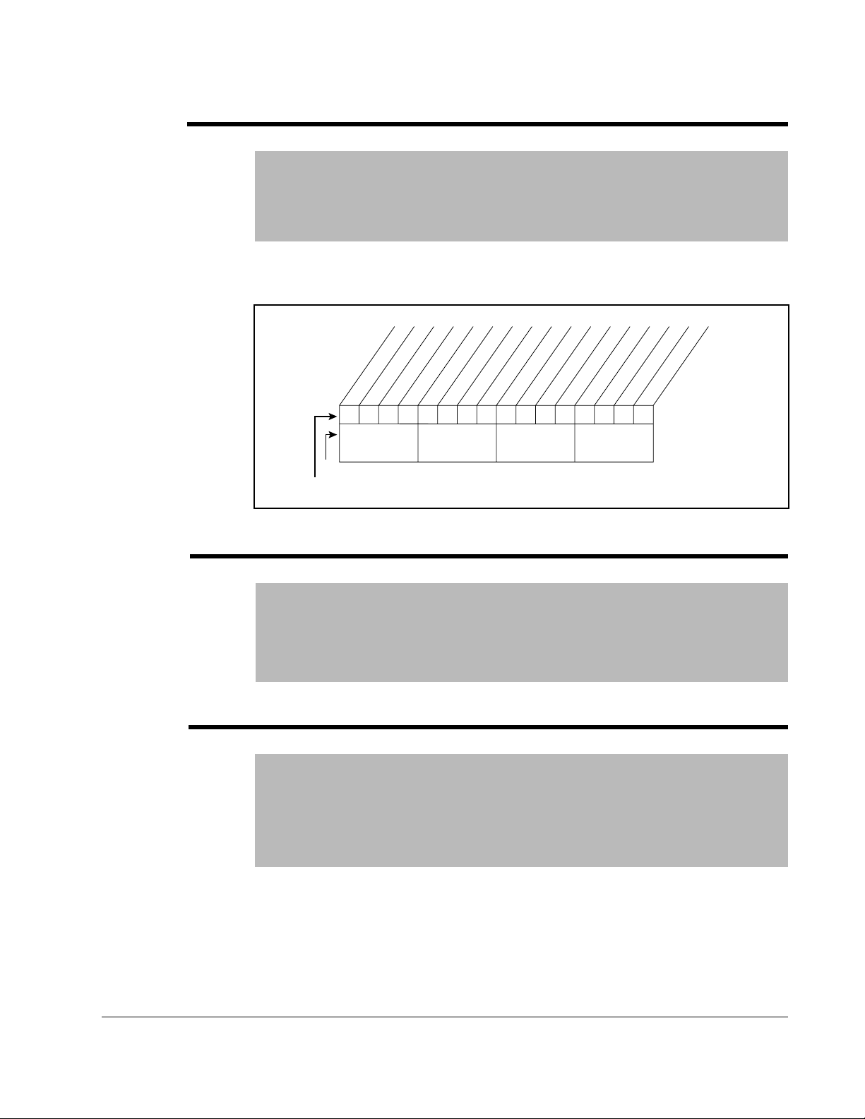
194 Save MOP Ref
Range: See figure 3.9
Default: See figure 3.9
Access: 2 Path: Utility>MOP Config
See also:
Enables/disables the feature that saves the present MOP (motor-operated
potentiometer) frequency reference at power down or at stop.
Bit #
Factory Default Bit Values
xxxxxxxxxxxx
10 01234567891112131415
Nibble 1Nibble 2Nibble 3Nibble 4
Figure 3.9 – Save MOP Ref (194)
At Stop
0xx0
At Powr Down
1
=Save
0
=Do Not Save
x =Reserved
195 MOP Rate
Range: 0.2 to Maximum Frequency [0.1 Hz/sec]
Default: 1.0 Hz/sec or 30.0 RPM/sec
Access: 2 Path: Utility>MOP Config
See also:
Sets the rate of change of the MOP reference in response to a digital input.
6.0 to Maximum Frequency [0.1 RPM/sec]
196 Param Access Lvl
Range: 0 = Basic
Default: 0 = Basic
Access: 2 Path: Utility>Drive Memory
See also:
Displays the present parameter access level.
The value of this parameter is not affected by a “Reset Defalts” command.
1 = Standard
2 = Advanced
Parameter Descriptions
3-53
Page 80

197 Reset to Defalts
Range: 0 = Ready
1 = Factory
2 = Low Voltage
3 = High Voltage
Default: 0 = Ready
Access: 0 Path: Utility>Drive Memory
See also: 41-47, 54, 55, 62, 63, 69-72, 82, 148, 158
Resets all parameter values to defaults except Language (201), Param Access Lvl
(196), Voltage Class (202) and Torq Prove Cnfg (600).
• Option 1 resets the drive to factory settings based on Voltage Class.
• Options 2 and 3 resets the drive to factory settings and sets alternate voltage and
current ratings.
Important: For Frames 5 and 6, the internal fan voltage may have to be changed
when using Option 2 or 3.
198 Load Frm Usr Set
Range: 0 = Ready
1 = User Set 1
2 = User Set 2
3 = User Set 3
Default: 0 = Ready
Access: 1 Path: Utility>Drive Memory
See also: 199
3-54
Loads a previously saved set of parameter values from a selected user set location in
drive non-volatile memory to active drive memory.
ATTENTION: The Reach Drive can be configured to use multiple saved
parameter (user) sets. Caution must be utilized to ensure that each user
!
This parameter is disabled while Dynamic User Set mode is active. Dyn UserSet Cnfg
(204), Dynamic Mode bit (0) = Enabled (1).
set is programmed for proper operation for the application. Recalling an
improperly programmed user set may cause rotation of the motor in an
undesired direction at unexpected speeds or may cause unpredictable
starting of the drive and motor. Failure to observe this precaution could
result in damage to equipment, severe bodily injury or loss of life.
DBT Reach Drive User Manual
Page 81

199 Save To User Set
Range: 0 = Ready
1 = User Set 1
2 = User Set 2
3 = User Set 3
Default: 0 = Ready
Access: 1 Path: Utility>Drive Memory
See also: 198
Saves the parameter values in active drive memory to a user set in drive non-volatile
memory.
200 Reset Meters
Range: 0 = Ready
Default: 0 = Ready
Access: 1 Path: Utility>Drive Memory
See also:
Resets selected meters to zero.
1 = MWh
2 = Elapsed Time
201 Language
Range: 0 = Not Selected
Default: 0 = Not Selected
Access: 2 Path: Utility>Drive Memory
See also:
1 = English
2 = Francais
3 = Espanol
4 = Italiano
5 = Deutsch
7 = Portugues
10 = Nederlands
Parameter Descriptions
Selects the display language when using an LCD HIM. Options 6, 8 and 9 are
reserved.
3-55
Page 82

202 Voltage Class
Range: 2 = Low Voltage
3 = High Voltage
4-5 = Reserved
Default: Based on Drive Type
Access: 2 Path: Utility>Drive Memory
See also: 41-47, 54, 55, 62, 63, 69-72, 82, 148, 158
Resets selected parameters that change the drive voltage rating, current rating,
scaling, and motor data. Maximum, Minimum and Default values for parameters
41-47, 54, 55, 62, 63, 69-72, 82, 148 and 158 will be affected by changing this
parameter.
203 Drive Checksum
Range: 0 to 65535 [1]
Default: Read Only
Access: 2 Path: Utility>Drive Memory
See also:
Provides a checksum value that indicates whether or not a change in drive
programming has occurred (data values only).
204 Dyn UserSet Cnfg
Range: See figure 3.10
Default: See figure 3.10
Access: 2 Path: Utility>Drive Memory
See also:
Enables/Disables dynamic selection of user parameter sets.
Bit #
Factory Default Bit Values
10 01234567891112131415
Figure 3.10 – Dyn UsrSet Cnfg
xxxxxxxxxxxx
Ctrl Source
0xx0
Dynamic Mode
Dynamic Mode
1
=Enabled
0
=Disabled
Ctrl Source
1
=[Dyn UserSet Sel]
0
=Digital Inputs
x =Reserved
3-56
DBT Reach Drive User Manual
Page 83

ATTENTION: The Reach Drive can be configured to use multiple saved
parameter (user) sets. Caution must be utilized to ensure that each user
!
set is programmed for proper operation for the application. Recalling an
improperly programmed user set may cause rotation of the motor in an
undesired direction at unexpected speeds or may cause unpredictable
starting of the drive and motor. Failure to observe this precaution could
result in damage to equipment, severe bodily injury or loss of life.
Important: In Dynamic Mode, changes to the parameters are not saved to nonvolatile
storage. Switching user sets restores the values last saved before
enabling dynamic mode.
205 Dyn UserSet Sel
Range: See figure 3.11
Default: See figure 3.11
Access: 2 Path: Utility>Drive Memory
See also:
Selects user set if Dyn UserSet Cnfg = xxxx xx11.
10 01234567891112131415
xxxxxxxxxxxx
Bit #
Factory Default Bit Values
Figure 3.11 – Dyn UsrSet Sel
1
=Enabled
0
=Disabled
Ctrl Source
1
=[Dyn UserSet Sel]
0
=Digital Inputs
x =Reserved
Ctrl Source
Dynamic Mode
Dynamic Mode
0xx0
ATTENTION: The Reach Drive can be configured to use multiple saved
parameter (user) sets. Caution must be utilized to ensure that each user
!
set is programmed for proper operation for the application. Recalling an
improperly programmed user set may cause rotation of the motor in an
undesired direction at unexpected speeds or may cause unpredictable
starting of the drive and motor. Failure to observe this precaution could
result in damage to equipment, severe bodily injury or loss of life.
Parameter Descriptions
3-57
Page 84

206 Dyn UserSet Actv
Range: See figure 3.12
Default: Read Only
Access: 2 Path: Utility>Drive Memory
See also:
Indicates the active user set and if the operation of the user set is dynamic or normal.
Bit #
209 Drive Status 1
Range: See figure 3.13
Default: Read Only
Access: 2 Path: Utility>Diagnostics
See also: 210
User Set 3
User Set 3
User Set 3
10 01234567891112131415
xxxxxxxxxxxx
Figure 3.12 – Dyn UserSet Actv
0000
Normal Mode
1
=Condition True
0
=Condition False
x =Reserved
Present operating condition of the drive.
(2)
Spd Ref ID 0
Spd Ref ID 1
Spd Ref ID 2
Spd Ref ID 3
Local ID 2
(1)
(1)
Local ID 0
At Speed
Local ID 1
(1)
(2)
(2)
(2)
10 01234567891112131415
Bit #
(2)
Bits
Description
0
0
0
0
0
0
0
0
0
1
0
0
1
0
1
0
0
1
0
0
1
1
0
1
1
1
0
0
1
0
0
1
0
1
1
0
1
1
1
0
1
1
0
1
1
1
1
1
1
Ref A Auto
1
Preset 1 Auto
0
Preset 2 Auto
1
Preset 3 Auto
0
Preset 4 Auto
1
Preset 5 Auto
0
Preset 6 Auto
1
Preset 7 Auto
0
TB Manual
1
Port 1 Manual
0
Port 2 Manual
1
Port 3 Manual
0
Port 4 Manual
1
Port 5 Manual
0
Port 6 Manual
1
Jog Ref
Faulted
Alarm
Accelerating
Decelerating
Actual Dir
(1)
Bits
0
0
0
0
0
1
0
1
0
0
1
1
1
0
0
1
0
1
1
1
0
1
1
1
Active
Ready
Command Dir
1
0110000001110000
0
x =Reserved
Description15 14 13 12 11 10 9
Por t 0 (TB)
Por t 1
Por t 2
Por t 3
Por t 4
Por t 5
Por t 6
No Local Control
=Condition True
=Condition False
3-58
Figure 3.13 – Drive Status 1 (209)
DBT Reach Drive User Manual
Page 85

210 Drive Status 2
Range: See figure 3.14
Default: Read Only
Access: 2 Path: Utility>Diagnostics
See also: 209
Present operating condition of the drive.
Bit #
211 Drive Alarm 1
Range: See figure 3.15
PTC
H
R
xx
W
eserved
eg
tdn
ct
it
verld
otor O
us Freq R
PI at 500 k
C
B
D
M
10 01234567891112131415
Figure 3.14 – Drive Status 2 (210)
urr Lim
utoR
A
st A
utoR
A
st C
B
D
ctive
A
utoTuning
A
B
C
D
raking
Stopping
Jogging
unning
R
00000000000000
ctive
A
R
eady
1
0
x =Reserved
=Condition True
=Condition False
Default: Read Only
Access: 1 Path: Utility>Diagnostics
See also: 212
Indicates Type 1 alarm conditions that currently exist in the drive. Note that for alarm
conditions not configured in Alarm Config 1 (259), the status indicated will be a zero.
arn
Ground W
Brk Slipped
Load Loss
aking
In PhaseLoss
Decel Inhibt
Motor Therm
W
10 01234567891112131415
Reserved
Drv OL Lvl 1
Drv OL Lvl 2
x
000000000
Anlg in Loss
IntDBRes OH
Power Loss
Str At PwrUp
UnderVoltage
000000
Prechrg Actv
1
=Condition True
0
=Condition False
x =Reserved
Bit #
PTC HW
Prof SetHome
1
00
xxxxxxxxxxxxx
26 161718192021222324252728293031
=Condition True
x
0
=Condition False
x =Reserved
Bit #
Figure 3.15 – Drive Alarm 1 (211)
Parameter Descriptions
3-59
Page 86

212 Drive Alarm 2
Range: See figure 3.16
Default: Read Only
Access: 1 Path: Utility>Diagnostics
See also: 211
Indicates Type 2 alarm conditions that currently exist in the drive.
Bit #
Bit #
Brk Slipped
TB Ref Cflct
PTC Conflict
DigIn CflctC
Sleep Config
Ixo Vlt Rang
SpdRef Cflct
10 01234567891112131415
26 161718192021222324252728293031
FlxAmps Rang
VHz NegSlope
IR Vlts Rang
MtrTyp Cflct
NP Hz Cflct
MaxFrq Cflct
Bipolr Cflct
0000000000000000
UserSetCflct
PICfgCflct
xxx0xxxxxxxxxxxx
Figure 3.16 – Drive Alarm 2 (212)
DigIn CflctA
DigIn CflctB
1
=Condition True
0
=Condition False
x =Reserved
TrqPrv Cflct
ProfStpCflct
1
=Condition True
0
=Condition False
x =Reserved
3-60
DBT Reach Drive User Manual
Page 87

213 Speed Ref Source
Range: 0 = PI Output
Default: Read Only
Access: 2 Path: Utility>Diagnostics
See also: 90, 93, 96, 101
1 = Analog In 1
2 = Analog In 2
3-6 = Reserved
7 = Pulse In
8 = Encoder
9 = MOP Level
10 = Jog Speed
11 = Preset Spd 1
12 = Preset Spd 2
13 = Preset Spd 3
14 = Preset Spd 4
15 = Preset Spd 5
16 = Preset Spd 6
17 = Preset Spd 7
18 = Local HIM
19 = DPI Port 2
20 = DPI Port 3
21 = DPI Port 4
22 = Network
23 = Reserved
24 = Auto Tune
25 = Jog Speed 2
26 = Scale Block 1
27 = Scale Block 2
28 = Scale Block 3
29 = Scale Block 4
30 = Pos/Spd Ref
31 = Position Reg
32 = Micro Pos
33 = Homing
34 = Decel Switch
35 = End Switch
36 = Unipolar Lim
37 = Rev Dis Lim
38 = Max Spd Lim
39 = Min Spd Lim
40 = Rev Spd Lim
41 = Load Trq Lim
214 Start Inhibits
Parameter Descriptions
Displays the source of the speed reference of the drive.
Range: See figure 3.17
Default: Read Only
Access: 2 Path: Utility>Diagnostics
See also:
Displays the inputs currently preventing the drive from starting.
3-61
Page 88

DPI Port 5
xx
Bit #
215 Last Stop Source
Range: 0 = Pwr Removed
1 = Local HIM
2 = DPI Port 2
3 = DPI Port 3
4 = Reserved
5 = Network
6 = Reserved
7 = Digital In
8 = Fault
9 = Not Enabled
10 = Sleep
11 = Jog
12 = Autotune
13 = Precharge
Default: Read Only
Access: 2 Path: Utility>Diagnostics
See also: 361-366
x
Param
Startup Actv
DPI Port 1
Digital In
DPI Port 2
DPI Port 4
DPI Port 3
100000
10 01234567891112131415
Figure 3.17 – Start Inhibits (214)
s Reset
DC Bus Pchrg
Stop Assertd
Type 2 Alarm
Enable
0000100
Fault
1
=Inhibit True
0
=Inhibit False
x =Reserved
Displays the source that initiated the most recent stop sequence. It will be cleared (set
to 0) during the next start sequence.
216 Dig In Status
Range: See figure 3.18
Default: Read Only
Access: 2 Path: Utility>Diagnostics
See also: 361-366
Current state of the digital inputs on the terminal block.
Bit #
Inputs & Outputs> Digital Inputs
Digital In2
Digital In1
Digital In3
Digital In4
Digital In5
Digital In6
xxxxxxxxxx
10 01234567891112131415
Figure 3.18 – Dig In Status (216)
000000
Nibble 1Nibble 2Nibble 3Nibble 4
1
=Input Present
0
=Input Not Present
x =Reserved
3-62
DBT Reach Drive User Manual
Page 89

217 Dig Out Status
Range: See figure 3.19
Default: Read Only
Access: 2 Path: Utility>Diagnostics
See also: 380-384
Current state of the digital outputs.
Bit #
218 Drive Temp
Range: 0 to 100.0 degC [0.1 degC]
Inputs & Outputs>Digital Outputs
Digital Out1
Digital Out2
Digital Out3
xxxxxxxxxxxx
10 01234567891112131415
Figure 3.19 – Dig Out Status (276)
00x0
1
=Output Energized
0
=Output De-energized
x =Reserved
Default: Read Only
Access: 2 Path: Utility>Diagnostics
See also:
Present operating temperature of the drive power section.
219 Drive OL Count
Range: 0.0 to 100.0% [0.1%]
Default: Read Only
Access: 2 Path: Utility>Diagnostics
See also: 150
Accumulated percentage of drive overload. Continuously operating the drive over
100% of its rating will increase this value to 100% and cause a drive fault.
Parameter Descriptions
3-63
Page 90

220 Motor OL Count
Range: 0.0 to 100.0% [1.0%]
Default: Read Only
Access: 2 Path: Utility>Diagnostics
See also: 47, 48
Accumulated percentage of motor overload. Continuously operating the motor over
100% of the motor overload setting will increase this value to 100% and cause a drive
fault.
221 Mtr OL Trip Time
Range: 0.0 to 99999 [1]
Default: Read Only
Access: 2 Path: Utility>Diagnostics
See also: 220
Amount of time before a Drive Overload fault occurs if the load condition remains
constant. A value of 99999 means that the drive is operating under the overload level.
224 Fault Speed
Range: 0.0 to +Maximum Freq [0.1 Hz]
0.0 to +Maximum Speed [0.1 RPM]
Default: Read Only
Access: 2 Path: Utility>Diagnostics
See also: 79, 225-230
3-64
Captures and displays the output speed of the drive at the time of the last fault.
225 Fault Amps
Range: 0.0 to Rated Amps x 2 [0.1 Amps]
Default: Read Only
Access: 2 Path: Utility>Diagnostics
See also: 224-230
Captures and displays motor amps at the time of the last fault.
DBT Reach Drive User Manual
Page 91

226 Fault Bus Volts
Range: 0.0 to Max Bus Volts [0.1 VDC]
Default: Read Only
Access: 2 Path: Utility>Diagnostics
See also: 224-230
Captures and displays the DC bus voltage of the drive at the time of the last fault.
227 Status 1 @ Fault
Range: See figure 3.20
Default: Read Only
Access: 2 Path: Utility>Diagnostics
See also: 209, 224-230
Captures and displays Drive Status 1 bit pattern at the time of the last fault.
Spd Ref ID 3
Spd Ref ID 2
Bit #
Spd Ref ID 1
Spd Ref ID 0
Local ID 1
Local ID 2
10 01234567891112131415
At Speed
Faulted
Local ID 0
Decelerating
Alarm
Command Dir
Actual Dir
Accelerating
Nibble 1Nibble 2Nibble 3Nibble 4
Active
0110000101110000
Ready
1
=Condition True
0
=Condition False
x =Reserved
228 Status 2 @ Fault
Parameter Descriptions
Figure 3.20 – Status 1 @ Fault (227)
Range: See figure 3.21
Default: Read Only
Access: 2 Path: Utility>Diagnostics
See also: 210, 224-230
Captures and displays Drive Status 2 bit pattern at the time of last fault.
Ready
Active
Running
Jogging
DC Braking
AutoTuning
Stopping
00000000000000
1
=Condition True
0
=Condition False
x =Reserved
Bit #
PTC HW
x
0
DPI at 500 k
Reserved
AutoRst Act
DB Active
AutoRst Ctdn
Curr Limit
Motor Overld
Bus Freq Reg
10 01234567891112131415
Figure 3.21 – Status 2 @ Fault (228)
3-65
Page 92
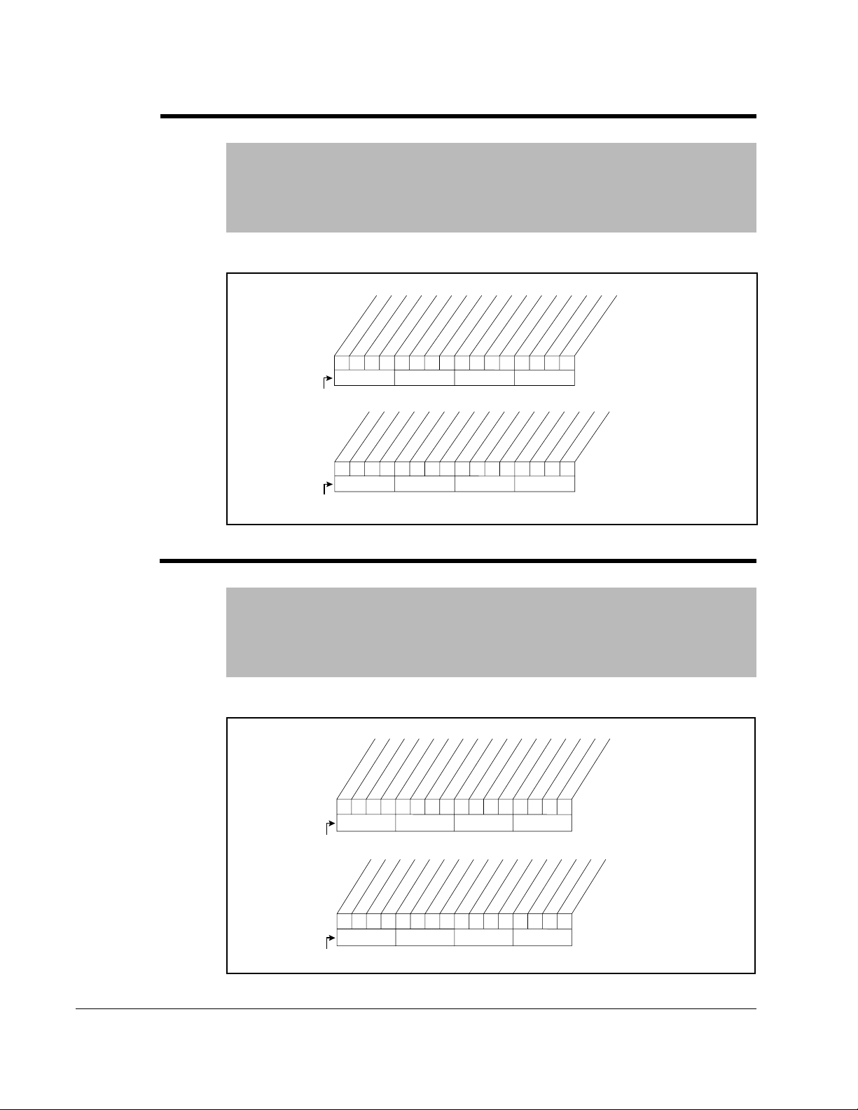
229 Alarm 1 @ Fault
Range: See figure 3.22
Default: Read Only
Access: 1 Path: Utility>Diagnostics
See also: 211, 224-230
Captures and displays Drive Alarm 1 at the time of the last fault.
Brk Slipped
Ground Warn
Bit #
Bit #
230 Alarm 2 @ Fault
Range: See figure 3.23
Default: Read Only
Access: 1 Path: Utility>Diagnostics
See also: 211, 221-230
Captures and displays Drive Alarm 2 bit pattern at the time of last fault.
Reserved
Anlg in Loss
Drv OL Lvl 1
x
000000000
IntDBRes OH
xxxxxxxxxxxxx
Decel Inhibt
Waking
Drv OL Lvl 2
In PhaseLoss
Motor Therm
Load Loss
10 01234567891112131415
26 161718192021222324252728293031
Figure 3.22 – Alarm 1 @ Fault (229)
UnderVoltage
Power Loss
Str At PwrUp
000000
Prof SetHome
PTC HW
00
x
Prechrg Actv
1
=Condition True
0
=Condition False
x =Reserved
1
=Condition True
0
=Condition False
x =Reserved
3-66
Bit #
Bit #
Brk Slipped
TB Ref Cflct
PTC Conflict
Ixo Vlt Rang
SpdRef Cflct
FlxAmps Rang
Sleep Config
VHz NegSlope
IR Vlts Rang
MtrTyp Cflct
NP Hz Cflct
MaxFrq Cflct
DigIn CflctB
DigIn CflctC
Bipolr Cflct
0000000000000000
10 01234567891112131415
ProfStpCflct
UserSetCflct
PICfgCflct
xxx0xxxxxxxxxxxx
26 161718192021222324252728293031
Figure 3.23 – Alarm 2 @ Fault (230)
DigIn CflctA
1
=Condition True
0
=Condition False
x =Reserved
TrqPrv Cflct
1
=Condition True
0
=Condition False
x =Reserved
DBT Reach Drive User Manual
Page 93

234 Testpoint 1 Sel
4
4
Range: 0 to 65535 [1]
Default: 499
Access: 2 Path: Utility>Diagnostics
See also: 235
Selects the function whose value is displayed in Testpoint 1 Data (235). These are
internal values that are not accessible through parameters.
See Testpoint Codes and Functions in chapter 12 for a list of codes and functions.
235 Testpoint 1 Data
Range: -/+ 2147483648 [1]
Default: Read Only
Access: 2 Path: Utility>Diagnostics
See also: 234
The present value of the function selected in Testpoint 1 Sel (234).
236 Testpoint 2 Sel
Range: 0 to 65535 [1]
Default: 499
Access: 2 Path: Utility>Diagnostics
See also: 237
Selects the function whose value is displayed in Testpoint 2 Data (237). These are
internal values that are not accessible through parameters.
See the Testpoint Codes and Functions in chapter 12 for a list of codes and functions.
237 Testpoint 2 Data
Range: -/+ 2147483648 [1]
Default: Read Only
Access: 2 Path: Utility>Diagnostics
See also: 236
The present value of the function selected in Testpoint 2 Sel (236).
Parameter Descriptions
3-67
Page 94

238 Fault Config 1
3
3.24
3.24
Range: See figure 11.24
Default: See figure 11.24
Access: 2 Path: Utility>Faults
See also:
Enables/disables annunciation of the faults shown in figure 11.24.
xx
Bit #
Factory Default Bit Values
240 Fault Clear
Range: 0 = Ready
1 = Clear Faults
2 = Clr Flt Que
Default: 0 = Ready
Access: 2 Path: Utility>Faults
See also:
Resets a fault and clears the fault queue.
241 Fault Clear Mode
Range: 0 = Disabled
1 = Enabled
Default: 1 = Enabled
Access: 2 Path: Utility>Faults
See also:
Reserved
Out PhaseLoss
ShearPNo Acc
PTC HW
x
000
10 01234567891112131415
Figure 3.24 – Fault Config 1 (238)
Motor Therm
In PhaseLoss
Load Loss
AutRst Tries
Decel Inhibt
Reserved
Shear Pin
Motor OverLd
x
10001000
UnderVoltage
1
Power Loss
1
=Enabled
0
=Disabled
x =Reserved
3-68
Enables/disables a fault reset (clear faults) attempt from any source. This does not
apply to fault codes, which are cleared indirectly via other actions.
DBT Reach Drive User Manual
Page 95

242 Power Up Marker
Range: 0.0000 to 214748.3647 Hr [0.0001 Hr]
Default: Read Only
Access: 2 Path: Utility>Faults
See also: 244, 246, 248, 250, 252, 254, 256, 258
Elapsed hours since initial drive power up. This value will rollover to 0 after the drive
has been powered on for more than the maximum value shown.
243
245
247
249
251
253
255
257
244
246
248
250
252
254
256
258
Fault 1 Code
Fault 2 Code
Fault 3 Code
Fault 4 Code
Fault 5 Code
Fault 6 Code
Fault 7 Code
Fault 8 Code
Range: 0000 to 65535
Default: Read Only
Access: 2 Path: Utility>Faults
See also:
A code that represents a drive fault. The codes will appear in these parameters in the
order they occur. Fault 1 Code = the most recent fault.
Fault 1 Time
Fault 2 Time
Fault 3 Time
Fault 4 Time
Fault 5 Time
Fault 6 Time
Fault 7 Time
Fault 8 Time
Range: 0.0000 to 214748.3647 [0.0001 Hr]
Default: Read Only
Access: 2 Path: Utility>Faults
See also: 242
Parameter Descriptions
The time between initial power up and the occurrence of the associated trip fault. Can
be compared to Power Up Marker for the time from the most recent power up.
Fault x Time - Power Up Marker = Time difference to the most recent power up. A
negative value indicates a fault occurred before the most recent power up. A positive
value indicates a fault occurred after the most recent power up.
3-69
Page 96

259 Alarm Config 1
Range: See figure 3.25
Default: See figure 3.25
Access: 2 Path: Utility>Alarms
See also:
Enables/disables alarm conditions that will initiate a drive alarm.
261 Alarm Clear
262
263
264
265
266
267
268
269
Range: 0 = Ready
Default: 0 = Ready
Access: 1 Path: Utility>Alarms
See also: 262 - 269
Resets all Alarm1 - 8 Code parameters (262 - 269) to zero.
Alarm 1 Code
Alarm 2 Code
Alarm 3 Code
Alarm 4 Code
Alarm 5 Code
Alarm 6 Code
Alarm 7 Code
Alarm 8 Code
1 = Clr Alarm Que
Bit #
Brk Slipped
Ground Warn
In PhaseLoss
Motor Therm
Load Loss
Waking
10 01234567891112131415
26 161718192021222324252728293031
Figure 3.25 – Alarm Config 1 (259)
Decel Inhibt
Drv OL Lvl 1
Drv OL Lvl 2
000000000
Reserved
x
IntDBRes OH
Power Loss
Str At PwrUp
Anlg in Loss
000000
PTC HW
00
xxxxxxxxxxxxx
Prechrg Actv
UnderVoltage
1
=Condition True
0
=Condition False
x =Reserved
Prof SetHome
1
=Condition True
x
0
=Condition False
x =Reserved
3-70
Range: 0 to 65535 [1]
Default: Read Only
Access: 1 Path: Utility>Alarms
See also: 261
A code that represents a drive alarm. The codes will appear in the order that the
alarms occur. The first code in is the first out. A time stamp is not available with
alarms.
DBT Reach Drive User Manual
Page 97

270 DPI Baud Rate
Range: 0 = 125 kbps
1 = 500 kbps
Default: 1 = 500 kbps
Access: 2 Path: Communication>Comm Control
See also:
Sets the drive rate for attached drive peripherals. The drive must be reset for the
change in value to be effected.
271 Drive Logic Rslt
Range: See figure 3.26
Default: Read Only
Access: 2 Path: Communication>Comm Control
See also:
The final logic command to the drive resulting from the combination of all port
requests and masking functions. Each bit or set of bits represent a command to the
drive or follower device.
(1)
(1)
(1)
Bit #
Spd Ref ID 1
Spd Ref ID 2
MOP Dec
Spd Ref ID 0
0
0
0
0
1
1
1
1
Forward
Decel 1
Decel 2
Accel 1
Accel 2
Reverse
Local Contrl
Mop Inc
10 01234567891112131415
(1)
Bits
Description14 13 12
No Command - Man. Mode
0
0
0
1
1
0
0
1
1
Ref A Auto
1
Preset 2 Auto
0
Preset 3 Auto
1
Preset 4 Auto
0
Preset 5 Auto
1
Preset 6 Auto
0
Preset 7 Auto
1
Figure 3.26 – Drive Logic Rslt (271)
Jog
Clear Fault
0110000101110000
Nibble 1Nibble 2Nibble 3Nibble 4
Start
Stop
1
=Condition Active
0
=Condition Inactive
x =Reserved
Parameter Descriptions
3-71
Page 98

272 Drive Ref Rslt
Range: -/+32767 [1]
Default: Read Only
Access: 2 Path: Communication>Comm Control
See also:
Present frequency reference scaled as a DPI reference for peer-to-peer
communications. The value shown is the output prior to the accel/decel ramp and any
corrections supplied by slip comp, PI, etc.
273 Drive Ramp Rslt
Range: -/+32767 [1]
Default: Read Only
Access: 2 Path: Communication>Comm Control
See also:
Present frequency reference scaled as a DPI reference for peer-to-peer
communications. The value shown is the value after the accel/decel ramp but prior to
any corrections supplied by slip comp, PI, etc.
274 DPI Port Sel
Range: 0 = Not Used
Default: 0 = Not Used
Access: 2 Path: Communication>Comm Control
See also:
1 = DPI Port 1
2 = DPI Port 2
3 = DPI Port 3
4 = DPI Port 4
5 = DPI Port 5
3-72
Selects which DPI port reference value will appear in DPI Port Value (275).
275 DPI Port Value
Range: -/+32767 [1]
Default: Read Only
Access: 2 Path: Communication>Comm Control
See also:
Value of the DPI reference selected in DPI Port Sel (274).
DBT Reach Drive User Manual
Page 99

.
276 Logic Mask
Range: See figure 3.27
Default: See figure 3.27
Access: 2 Path: Communication>Masks & Owners
See also: 288-297
Determines which ports can control the drive when Write Mask Act (597), bit 15 is set
to “1.” If the bit for a port is set to “0,” the port will have no control functions except for
stop.
10 01234567891112131415
Bit #
Factory Default Bit Values
Figure 3.27 – Logic Mask (276)
DPI Port 5
DPI Port 4
DPI Port 3
DPI Port 1
DPI Port 2
111111xxxxxxxxxx
Digital In
1
=Control Permitted
0
=Control Mask
x =Reserved
277 Start Mask
Range: See figure 3.27
Default: See figure 3.27
Access: 2 Path: Communication>Masks & Owners
See also: 288-297
Controls which adapters can issue start commands.
278 Jog Mask
Range: See figure 3.27
Default: See figure 3.27
Access: 2 Path: Communication>Masks & Owners
See also: 288-297
Controls which adapters can issue jog commands.
Parameter Descriptions
3-73
Page 100

279 Direction Mask
Range: See figure 3.27
Default: See figure 3.27
Access: 2 Path: Communication>Masks & Owners
See also: 288-297
Controls which adapters can issue forward/reverse direction commands.
280 Reference Mask
Range: See figure 3.27
Default: See figure 3.27
Access: 2 Path: Communication>Masks & Owners
See also: 288-297
Controls which adapters can select an alternate reference.
281 Accel Mask
Range: See figure 3.27
Default: See figure 3.27
Access: 2 Path: Communication>Masks & Owners
See also: 288-297
3-74
Controls which adapters can select Accel Time 1 (140) and Accel Time 2 (141).
282 Decel Mask
Range: See figure 3.27
Default: See figure 3.27
Access: 2 Path: Communication>Masks & Owners
See also: 288-297
Controls which adapters can select Decel Time 1 (142) and Decel Time 2 (143).
283 Fault Clr Mask
Range: See figure 3.27
Default: See figure 3.27
Access: 2 Path: Communication>Masks & Owners
See also: 288-297
Controls which adapters can clear a fault.
DBT Reach Drive User Manual
 Loading...