

Page 1
External Bus Resistor Kit
for LiquiFlo AC Drives
Drive M/N’s 41L4060, 41LR4060, LF150414W4
Instruction Manual D2-3535
ATTENTION: Only qualified electrical personnel familiar with the construction and operation of this
equipment and the hazards involved should install, adjust, operate, or service this equipment. Read and
!
understand this manual and other applicable manuals in their entirety before proceeding. Failure to
observe this precaution could result in severe bodily injury or loss of life.
ATTENTION: Do not install or remove modification kits with power applied to the drive. Disconnect
and lock out incoming power before attempting such installation or removal. Failure to observe this
!
precaution could result in severe bodily injury or loss of life.
ATTENTION: DC Bus capacitors retain hazardous voltages after input power has been disconnected.
After disconnecting input power, wait five (5) minutes for the DC bus capacitors to discharge and then
!
check the voltage with a voltmeter to ensure that the DC bus capacitors are discharged before touching
any internal components. Failure to observe this precaution could result in severe bodily injury or loss of
life.
ATTENTION: The user is responsible for conforming with all applicable local, national, and
international codes. Failure to observe this precaution could result in damage to, or destruction of, the
!
equipment.
ATTENTION: The drive contains ESD- (Electrostatic Discharge) sensitive parts and assemblies. Static
control precautions are required when installing, testing, servicing or repairing the drive. Erratic machine
!
operation and damage to, or destruction of, equipment can result if this procedure is not followed.
Failure to observe this precaution could result in severe bodily injury or loss of life.
What the Kit
Contains
External Resistor Kit M/N 180788-A02 can be used only with B-frame (414A)
LiquiFlo AC drives, model numbers: 41L4060, 41LR4060 and LF150414W4. Verify
that you have the correct resistor assembly by verifying that the harness is labeled,
“414AMP EXT BUS RESIS KIT.”
Quantity: Description
1 Resistor Assembly
6 M4 x 16 Mounting Screws with captive locking hardware
1Protective Cover
1 Drilling Template / Cabinet Guard
This kit is for field upgrade only. You should not use it if you are replacing the drive. If
you replace the drive in the future, you should remove the resistor kit from the drive
system.
©2004 Rockwell Automation. All rights reserved.
Page 2
2 Instruction Manual D2-3535
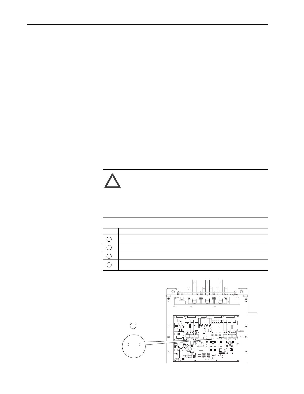
What You Need to Do
Step 1: Verifying the DC Bus
Capacitors are Discharged
To install the external bus resistor kit you need to:
❐ Step 1: Verify that the DC Bus Capacitors are discharged
❐ Step 2: Identify a mounting location for the resistor assembly
❐ Step 3: Drill mounting holes for the resistor assembly, using the
template
❐ Step 4: Mount the resistor assembly
❐ Step 5: Unplug connectors P1 and P2, and route harness
❐ Step 6: Connect the ground wire
❐ Step 7: Connect the harness
❐ Step 8: Verify installation
❐ Step 9: Register installation
ATTENTION: DC Bus capacitors retain hazardous voltages
after input power has been disconnected. After disconnecting
!
input power, wait five (5) minutes for the DC bus capacitors to
discharge and then check the voltage with a voltmeter to ensure
that the DC bus capacitors are discharged before touching any
internal components. Failure to observe this precaution could
result in severe bodily injury or loss of life.
Task Description
Turn off and lock out input power. Wait five minutes
A
Verify that there is no voltage at the drive’s input power terminals
B
Remove front cover
C
Measure the DC bus potential with a voltmeter while standing on a non-conductive surface
D
and wearing insulated gloves (1000V)
Test Points for initial
DC Bus Voltage
Measurement
Pos
(+)
D
J3
J4
TP1 TP2
D13
D34
U16
U22
R8 R9 R10
U32
U3
D31U8D30
D35
D61
U37
R11 R12 R13 R6
C6
D14
D15
U4
D25
U7
D32
U9
U17
U23
U24
D58
DS2
D62
U33
D63
J8
J5
R5
R7
RV2
RV6
RV7
RV8
J7
C12
C10
C11
D21
R25C17
D23
D22
C18 R26
C19
R27
U5
C21
T6
T7 T8
R34
R32
R33
C26
U11
U12
U10
D37
C28
D41
D42
D39
D40
C30
U18
U19
U20
D46
D45
D48
D47
U25
U26
D53
D54
D55
U27
U28
DS3
DS4
D59
C48
U34
J1
J6
RV1
R1
C1
C4
C2 C3
C5
Neg
(-)
TP2TP1
Q2Q1
D10
T1
D11
U1 C13
R19
D12
Q4
D16
T2
D24
L1
C20
U6
D26
C22
R36
R35
T10
Q5
D52
D49
D50
D51
U21
R37
Q6
T11
1
D56
D60
C39
C41
U36
C49
D65
D64
D66
C50
FUSE1
R14
R15
R16 R17
R2
R3J2R4
RV4
RV3
C8
C7
D18
R23
D17 R22
C15
C14
T3
T4 T5
C23
R29 R30
D27
T9
D29
DS1
U14
U15
D44
D43
C33
C32
C31
C38
C37
C36
C35
L2
FUSE2
C40
U29
U30
U35
C42
C44
C43
C45
R18
D3
D4
D2
D5
D1
D7
D8 D9
D6
RV5
Q3
C9
R20
C16 R24
D19
U2
R21
D20
R28
R31
D28
C24
C25
D33
C27
U13
D36
C29
D38
C34
Made in USA
BARCODE
ASSY
R38
R39 D57
R41
R40
R43
R42
U31
C47
C46
TP4TP5TP6 TP3
Page 3

Instruction Manual D2-3535 3
Step 2: Identifying the
Mounting Location
Consider the following factors when choosing the location for the resistor
assembly:
• the resistor assembly must be mounted inside the drive cabinet
• the resistor assembly must be mounted vertically, with the closed part of
the protective cover pointing towards the front of the enclosure
• the wiring harness must be able to reach connectors P1 and P2 inside the
drive
• the wiring harness must not pass over unprotected sharp edges or hot
surfaces
• the resistor assembly must not be mounted on the enclosure door
Resistor assembly shown without
harness for clarity
Towards
Enclosure
Door
Protective
Cover
Page 4
4 Instruction Manual D2-3535
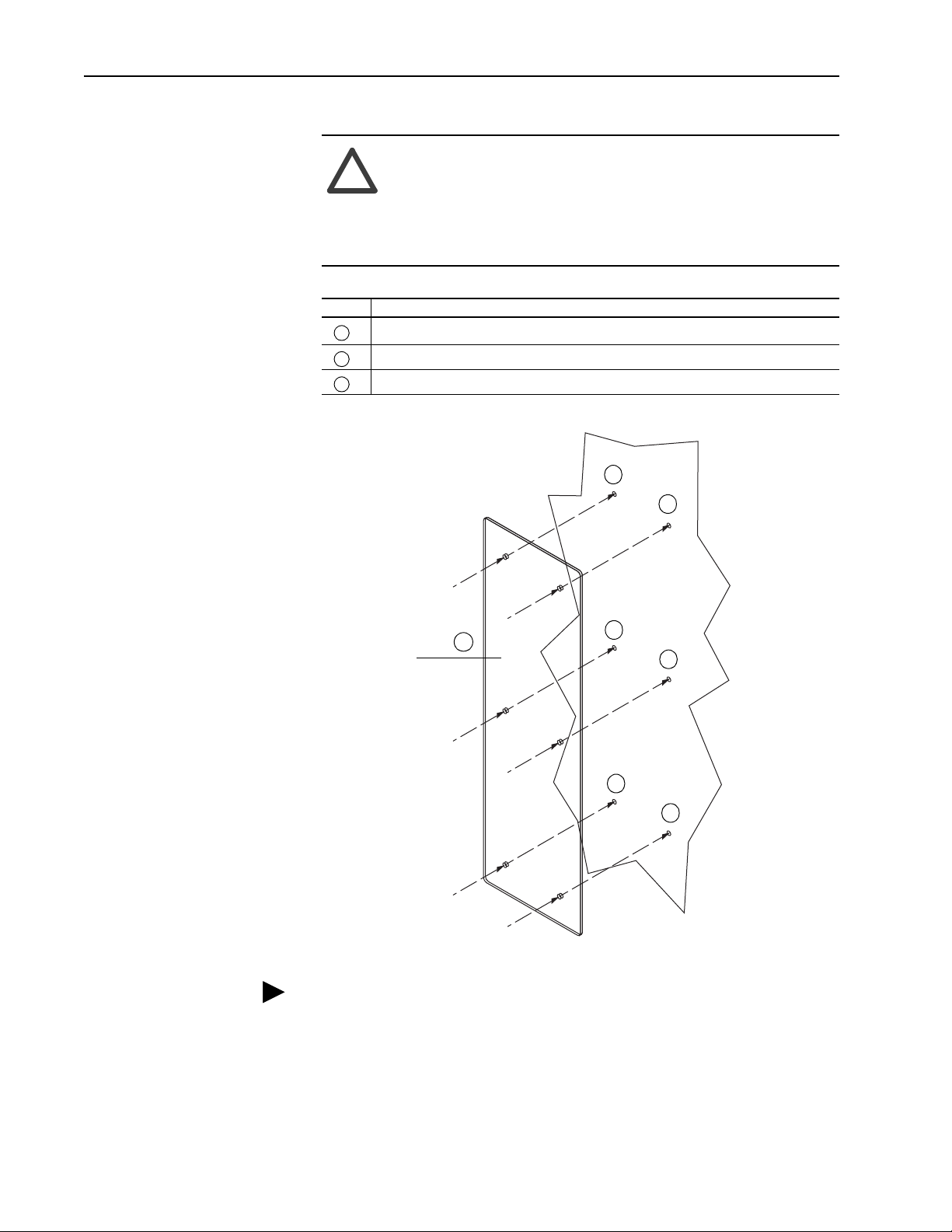
Step 3: Drilling the Mounting
Holes
ATTENTION: Metal debris or other foreign matter must be
kept from falling into the drive. Metal debris or other foreign
!
matter may become lodged in the drive circuitry resulting in
component damage. Failure to observe this precaution could
result in severe bodily injury or loss of life and/or damage to, or
destruction of, equipment.
Task Description
Protect internal components from drilling debris
A
Using the template, mark locations for six mounting holes
B
Drill six 5mm (3/16 inch) mounting holes
C
B
B
Drilling Template /
A
Cabinet Guard
TIP: The template is symmetrical, so you have the options of drilling from
the outside or inside of the enclosure. Drilling outside reduces the risk of
debris falling into the drive.
B
B
B
B
Page 5

Instruction Manual D2-3535 5
Step 4: Mounting the
Resistor Assembly
A
A
Task Description
Using a Phillips screw driver, install and tighten the six M4 x 16 mounting screws (torque 12
A
in-lb)
!
A
A
ATTENTION: The cabinet can be very hot where the resistor
assembly is mounted. HOT surfaces can cause severe burns. You
must install the cabinet guard to protect personnel from
accidental contact with the hot cabinet surface.
Cabinet Guard
Enclosure Wall
Resistor assembly
mounted on inside of
enclosure
A
Mounting Screws
inserted from outside
of enclosure
A
Resistor assembly shown
without harness for clarity
Page 6

6 Instruction Manual D2-3535
Step 5: Unplugging
Connectors P1 and P2 and
Routing the Wiring Harness
P1 and P2
Push Here
to Release
Connector
Locate the P1 and P2 Connectors near the upper-left part of the power
structure and unplug them.
To Resistor Assembly
Important: The harness connections are considered power level wiring.
Run them separately from I/O and signal wiring.
Page 7

Step 6: Connecting the
Ground Wire
Typical installations can use the existing ground stud originally intended for
grounding the enclosure door.
This figure illustrates recommended practices for connecting grounds to an
enclosure.
Ground Lug
Star Washer
Instruction Manual D2-3535 7
Welded Stud
BoltPaint Free
Area
Nut
Star Washer
Component
Ground Conductor
Ground Lug
Nut Component
Star Washer
Ground Conductor
Star Washer
Page 8

8 Instruction Manual D2-3535
Step 7: Connecting the
Harness
Task Description
Plug P1A into P1
A
Plug P2A into P2
B
Harness to Resistor Assembly
P1
A
P1A
P2A
P2
B
Wires
to
Drive
Wires
from
Drive
Page 9

Instruction Manual D2-3535 9
Step 8: Verifying the
Installation
J1
J6
RV1
R1
C1
C4
C2 C3
C5
Q2Q1
D10
T1
D11
U1 C13
R19
D12
Q4
D16
T2
D24
L1
C20
U6
D26
C22
R36
R35
T10
Q5
D52
D49
D50
D51
U21
R37
Q6
T11
1
D56
D60
C39
C41
U36
C49
D65
D64
D66
C50
FUSE1
Task Description
A
B
C
J3
R14
R15
R2
R3J2R4
RV4
RV3
D2
D1
D6
RV5
C8
C9
C7
D18
C16 R24
R23
D17 R22
C15
C14
D19
T3
T4 T5
R29 R30
U15
D43
FUSE2
C40
C43
R28
R31
D28
D27
C24
T9
D33
C27
U13
D36
D38
D44
C33
Made in USA
C38
C37
BARCODE
ASSY
L2
U29
U30
R38
R40
R42
U31
U35
C44
C45
C23
D29
DS1
U14
C32
C31
C36
C35
C42
Disconnect J4 from PMC Board
Confirm continuity between the points specified in Ta bl e A
Reconnect J4 to PMC Board
J4
Pin 1
R16 R17
Q3
A
B
J4
R9 R10
J5
R5
R11 R12 R13 R6
C6
C10
D21
D15
U5
D25
C21
T6
U7
R32
U10
D39
U18
U24
DS2
DS3
DS4
D59
C48
D62
U34
D63
J8
R11 R12
R7
RV2
RV6
RV7
RV8
J7
C12
C11
R25C17
D22
C18 R26
D23
C19
R27
T7 T8
R34
R33
C26
U11
U12
D37
C28
D41
D42
D40
C30
U19
U20
D46
D45
D47
D48
U25
U26
D53
D54
D55
U27
U28
C
J4
R18
R8 R9 R10
D3
D4
D5
D7
D8 D9
R20
U2
D14
D13
R21
D20
U3
U4
TP1 TP2
D32
D31U8D30
C25
U9
C29
D34
D35
C34
U16
U17
U23
U22
D58
R39 D57
U32
R41
D61
U33
R43
C47
C46
U37
TP4TP5TP6 TP3
Table A J4 Continuity Tests
J4:Pin 1 BUS (+) Continuity or
J4:Pin 3 BUS MID
J4:Pin 5 BUS (-)
(1)
If you are unfamiliar with continuity tests, refer to Performing Continuity
Te st s on page 9.
(2)
See Wiring Diagram for Reference on page 11.
Test Points
Resistor Assembly
End of Cable
(1)
(2)
Meter ReadingJ4 End of Cable
approximately zero ohms
Follow the normal steps for verifying drive installation and operation. Refer to the
drive Hardware Reference and Software Start-up manuals.
If you have a... ... refer to these publications:
LiquiFlo 1.0 drive
•
D2-3410,
LiquiFlo AC General Purpose (Volts/Hertz) and Vector Duty Drive
Software Start-up
•
D2-3411,
LiquiFlo AC Power Modules Hardware Reference, Installation and
Troubleshooting
LiquiFlo 1.5 drive
•
D2-3494,
LiquiFlo 1.5 AC Power Modules Hardware Reference, Installation,
and Troubleshooting
•
D2-3495,
LiquiFlo 1.5 AC General Purpose (Volts/Hertz) and Vector Duty
Drive Software Start-Up and Reference Manual
Performing Continuity Tests
In these tests you are verifying continuity, a short circuit, between the two test
points. The continuity mode on a digital multi-meter provides the easiest method
for performing this test. Place one meter lead on the first test point and the meter
should beep when you place the other lead on the second test point.
If your meter does not have a continuity mode, you can use a resistance mode.
Place one meter lead on the first test point and the meter should indicate a short
circuit (read approximately zero ohms) when you place the other lead on the
second test point.
Page 10

10 Instruction Manual D2-3535
Step 9: Registering
the Installation
C
Register the installation of the External Bus Resistor kit on the Rockwell
Automation Warranty And Returns Processing (WARP) website
http://www.automation.rockwell.com/warp/
(
Click on “Continue”
Click on “Field Retrofits”
A
).
B
Select “External Bus
Resistor Upgrade” from
the drop-down
D
Click on “Register Retrofit”
Enter all the required and
E
pertinent information.
Click on “Create Registration”
F
Page 11

Wiring Diagram for
Reference
Instruction Manual D2-3535 11
BUS (+)
BUS (-)
2600 Ohm
2600 Ohm
BUS MID
EXTERNAL BUS RESISTOR ASSEMBLY
RESISTOR 24708-501-12
1
P2
1
2
3
DISCHARGE RESISTOR
10K Ohms
Note:
The old resistors and their
connecting wires remain
in the drive.
1
2
3
R1 R2
DISCHARGE RESISTOR
10K Ohms
24708-501-13 24708-501-13
63481-105SFY OR 63481-105SFY OR
TEMP
SWITCH
CHILLPLATE
TEMP
SWITCH
REACTOR
FAN
9 8 7 6 5
4 2 3
DC+ BUS
DC MIDPT
DC- BUS
P2A
P1A
P1
1
1
2
BLEEDER (+)
4
4 2 3
4 5 6
3
BLEEDER (-)
6
5
TEMPSW1
7 8 9
FANPWR (+)
TEMPSW2
9 8 7
9 8 7 6 5
FANPWR (-)
Page 12

U.S. Drives Technical Support
Tel: (1) 262.512.8176, Fax: (1) 262.512.2222, Email: support@drives.ra.rockwell.com, Online: www.ab.com/support/abdrives
Trademarks not belonging to Rockwell Automation are property of their respective companies.
Publication D2-3535-July 2004 Copyright © 2004Rockwell Automation, Inc. All Rights Reserved. Printed in USA.
 Loading...