

Page 1

1769 CompactLogix Packaged Controllers
Catalog Numbers
1769-L23-QBFC1B
Quick Start and User Manual
1769-L23E-QB1B, 1769-L23E-QBFC1B,
Page 2
Important User Information
WARNING
IMPORTANT
ATTENTION
SHOCK HAZARD
BURN HAZARD
Solid state equipment has operational characteristics differing from those of electromechanical equipment. Safety Guidelines
for the Application, Installation and Maintenance of Solid State Controls (publication SGI-1.1
Automation sales office or online at http://www.rockwellautomation.com/literature/
between solid state equipment and hard-wired electromechanical devices. Because of this difference, and also because of the
wide variety of uses for solid state equipment, all persons responsible for applying this equipment must satisfy themselves that
each intended application of this equipment is acceptable.
In no event will Rockwell Automation, Inc. be responsible or liable for indirect or consequential damages resulting from the use
or application of this equipment.
The examples and diagrams in this manual are included solely for illustrative purposes. Because of the many variables and
requirements associated with any particular installation, Rockwell Automation, Inc. cannot assume responsibility or liability for
actual use based on the examples and diagrams.
No patent liability is assumed by Rockwell Automation, Inc. with respect to use of information, circuits, equipment, or software
described in this manual.
Reproduction of the contents of this manual, in whole or in part, without written permission of Rockwell Automation, Inc., is
prohibited.
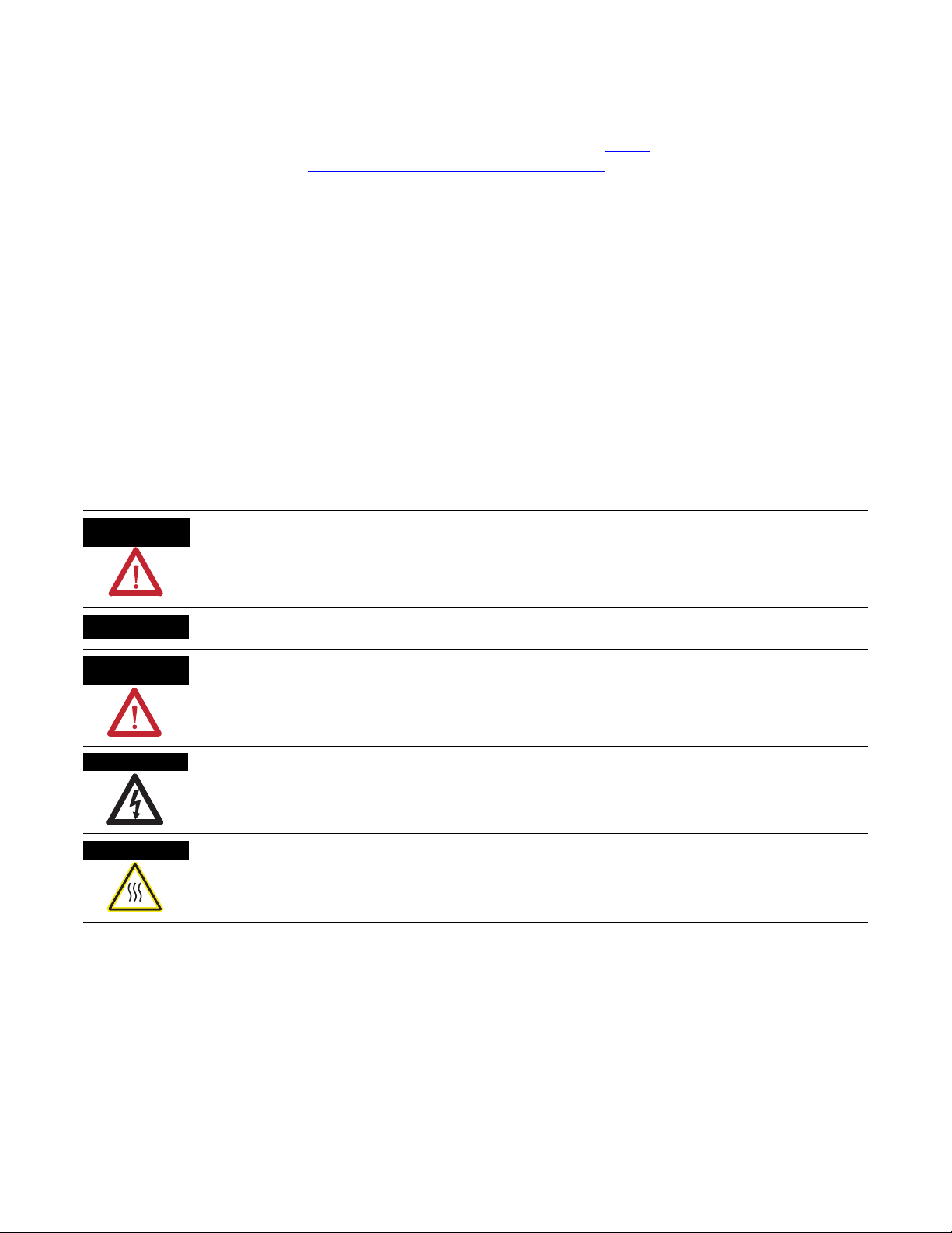
Throughout this manual, when necessary, we use notes to make you aware of safety considerations.
available from your local Rockwell
) describes some important differences
Identifies information about practices or circumstances that can cause an explosion in a hazardous environment,
which may lead to personal injury or death, property damage, or economic loss.
Identifies information that is critical for successful application and understanding of the product.
Identifies information about practices or circumstances that can lead to personal injury or death, property damage,
or economic loss. Attentions help you identify a hazard, avoid a hazard, and recognize the consequence
Labels may be on or inside the equipment, for example, a drive or motor, to alert people that dangerous voltage may
be present.
Labels may be on or inside the equipment, for example, a drive or motor, to alert people that surfaces may reach
dangerous temperatures.
Allen-Bradley, Rockwell Automation, Rockwell Software, CompactLogix, Point I/O, PowerFlex 40, PanelView Plus, Stratix 6000, Logix5000, RSLinx, RSLinx Enterprise, FactoryTalk View SE, and TechConnect are
trademarks of Rockwell Automation, Inc.
Trademarks not belonging to Rockwell Automation are property of their respective companies.
Page 3

Summary of Changes
Introduction
Updated Information
The release of this document contains new and updated information. Change
bars on the side of the page indicate new and updated information.
This document contains the following changes.
Topic Page
DH-485 Network Communication 184
Determine Expansion Module Limits 230
Expansion I/O RPI 231
Program the Packaged Controller 233
3Publication IASIMP-QS010B-EN-P - October 2009 3
Page 4

Summary of Changes
Notes:
4 Publication IASIMP-QS010B-EN-P - October 2009
Page 5
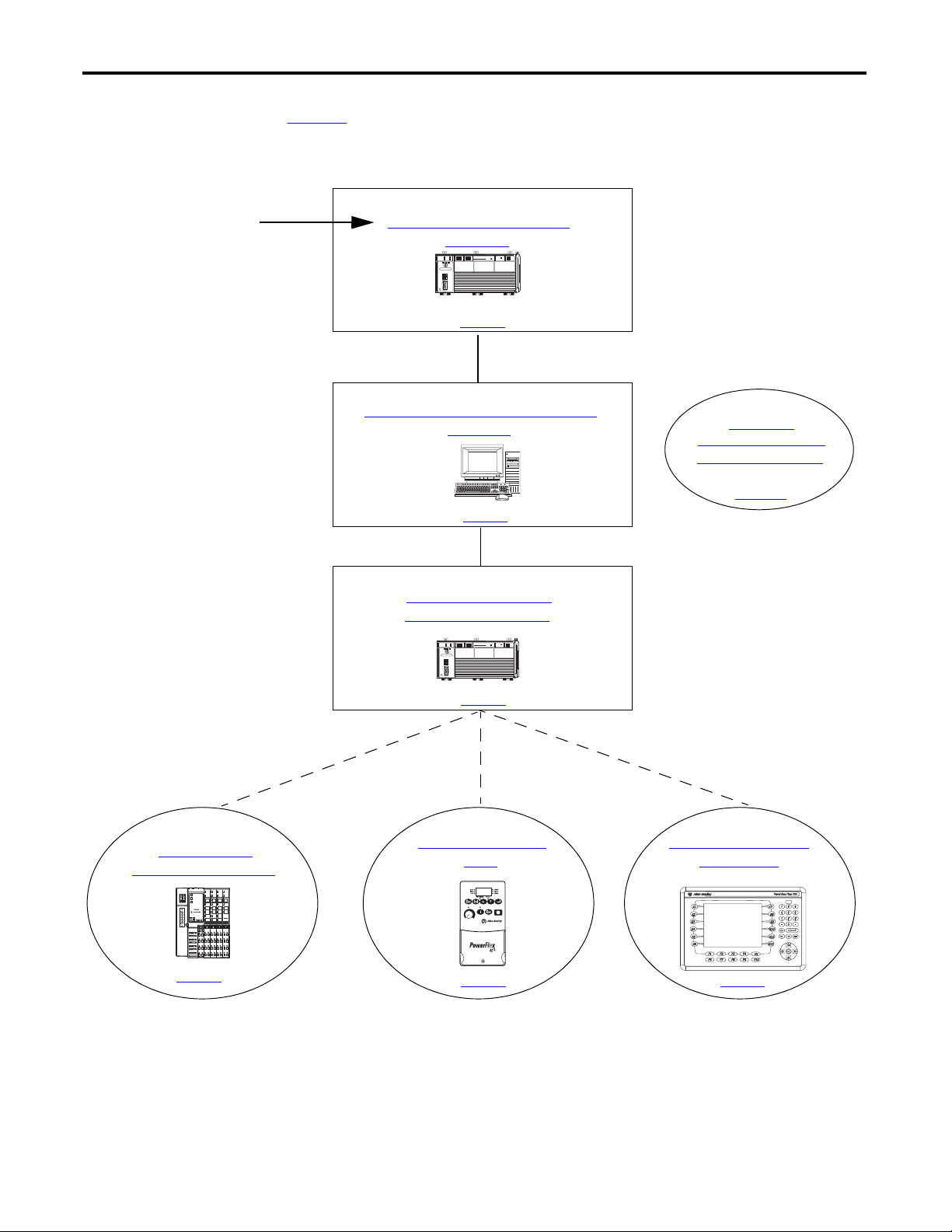
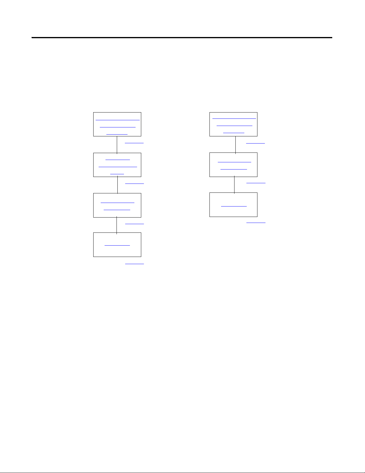
CompactLogix L23E
QBFC-1B
Chapter 3
Create a Project Using
RSLogix 5000 Software
Chapter 1
Assemble the CompactLogix
Hardware
Chapter 2
Prepare the Computer, Network, and
Controller
Chapter 7
Optional Configuration of the
DeviceNet Network
Chapter 4
Add POINT I/O
Modules to the Project
Chapter 5
Add a PowerFlex 40
Drive
Chapter 6
Add a PanelView Plus
600 Terminal
Optional
Depending on your system.
page 23
page 29
page 125
page 53
page 83
page 97
Optional Network
(not used to complete examples)
For general information about your packaged controller,
start with the User Manual on page 151
.
To begin using your packaged
controller, start here.
page 73
CompactLogix L23E
Where to Start
QBFC-1B
5Publication IASIMP-QS010B-EN-P - October 2009 5
Page 6
Where to Start
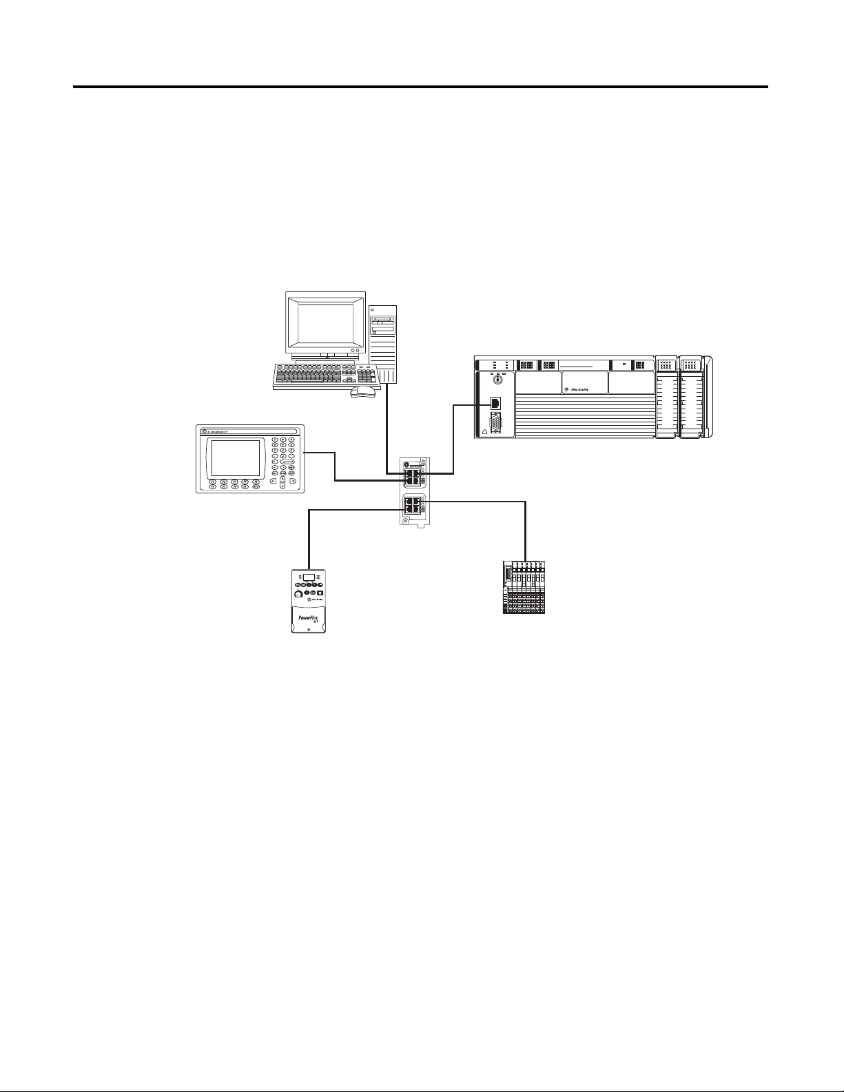
PanelView Plus 600PanelView Plus 600
PV+ 600
Stratix 6000 Switch
PowerFlex 40
Component Class
Drive
POINT I/O Modules
I/O
I/O
CompactLogix L23E
1769-L23E-QBFC1 or 1769-L23E-QB1B
Workstation
Configurations for Quick Start
This quick start demonstrates the use of this hardware and network configuration.
Option 1: 1769-L23E Packaged Controller with an EtherNet/IP Network
An Ethernet switch other than the Stratix 6000 switch may be used. For this quick start, the
Stratix 6000 switch is recommended.
6 Publication IASIMP-QS010B-EN-P - October 2009
Page 7
Where to Start
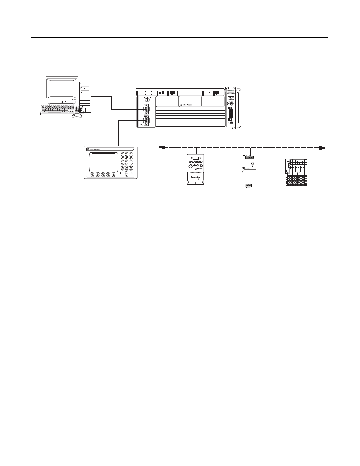
PanelView Plus 600PanelView Plus 600
PV+ 600
DeviceNet Network
PowerFlex 40
Component Class Drive
CompactLogix L23
POINT I/O Modules
1606
Power Supply
Workstation
Option 2: 1769-L23-QBFC1B Packaged Controller with a Serial Network
(1)
This option shows an example DeviceNet network that could be configured by using the
chapter, Optional - Configuration of the DeviceNet Network
(on page 125). While that
chapter provides a brief description of how to use a DeviceNet network with a 1769-L23
packaged controller, full details for using a DeviceNet network with any Logix5000 controller
are contained in the DeviceNet Modules in Logix5000 Control Systems User Manual,
publication DNET-UM004
Once you have selected your configuration, use the Parts List
.
on page 18 to determine what
hardware you need.
If you already have your hardware, proceed to Chapter 1
Hardware, on page 23.
, Assemble the CompactLogix
(1)
Publication IASIMP-QS010B-EN-P - October 2009 7
Page 8

Where to Start
Notes:
8 Publication IASIMP-QS010B-EN-P - October 2009
Page 9

Quick Start
Table of Contents
Preface
Assemble the CompactLogix
Hardware
About This Quick Start . . . . . . . . . . . . . . . . . . . . . . . . . . . . . . . . . . . . . 15
Required Software . . . . . . . . . . . . . . . . . . . . . . . . . . . . . . . . . . . . . . . . . 16
CompactLogix Packaged Controller Software Requirements . . . . 16
POINT I/O Modules and PowerFlex 40 Drive Software
Requirements . . . . . . . . . . . . . . . . . . . . . . . . . . . . . . . . . . . . . . . . . . 16
PanelView Plus Terminal Software Requirements. . . . . . . . . . . . . 16
DeviceNet Network Software Requirements. . . . . . . . . . . . . . . . . 17
Parts List. . . . . . . . . . . . . . . . . . . . . . . . . . . . . . . . . . . . . . . . . . . . . . . . . 18
Conventions . . . . . . . . . . . . . . . . . . . . . . . . . . . . . . . . . . . . . . . . . . . . . . 20
Additional Resources . . . . . . . . . . . . . . . . . . . . . . . . . . . . . . . . . . . . . . . 21
Chapter 1
Before You Begin. . . . . . . . . . . . . . . . . . . . . . . . . . . . . . . . . . . . . . . . . . 23
What You Need . . . . . . . . . . . . . . . . . . . . . . . . . . . . . . . . . . . . . . . . . . . 23
Follow These Steps . . . . . . . . . . . . . . . . . . . . . . . . . . . . . . . . . . . . . . . . 24
Connect the Battery to the Packaged Controller . . . . . . . . . . . . . . . . . 25
Record the Ethernet Address (MAC) . . . . . . . . . . . . . . . . . . . . . . . . . . 25
Make Network Connections . . . . . . . . . . . . . . . . . . . . . . . . . . . . . . . . . 26
Wire Power. . . . . . . . . . . . . . . . . . . . . . . . . . . . . . . . . . . . . . . . . . . . . . . 27
Additional Resources . . . . . . . . . . . . . . . . . . . . . . . . . . . . . . . . . . . . . . . 28
Prepare the Computer, Network,
and Controller
Create a Project Using
RSLogix 5000 Software
Chapter 2
Before You Begin. . . . . . . . . . . . . . . . . . . . . . . . . . . . . . . . . . . . . . . . . . 29
What You Need . . . . . . . . . . . . . . . . . . . . . . . . . . . . . . . . . . . . . . . . . . . 29
Follow These Steps . . . . . . . . . . . . . . . . . . . . . . . . . . . . . . . . . . . . . . . . 30
Terminology . . . . . . . . . . . . . . . . . . . . . . . . . . . . . . . . . . . . . . . . . . . . . . 31
Make Network Connections . . . . . . . . . . . . . . . . . . . . . . . . . . . . . . . . . 31
Install RSLogix 5000 Programming Software. . . . . . . . . . . . . . . . . . . . 33
Configure a Serial Driver . . . . . . . . . . . . . . . . . . . . . . . . . . . . . . . . . . . . 38
Set the IP Address for the Computer . . . . . . . . . . . . . . . . . . . . . . . . . . 40
Assign an IP Address to the Packaged Controller . . . . . . . . . . . . . . . . 42
Configure the EtherNet/IP Driver in RSLinx Software . . . . . . . . . . . 44
Browse the EtherNet/IP Network in RSLinx Software . . . . . . . . . . . 45
Load Firmware . . . . . . . . . . . . . . . . . . . . . . . . . . . . . . . . . . . . . . . . . . . . 46
Install Additional Software . . . . . . . . . . . . . . . . . . . . . . . . . . . . . . . . . . 50
Additional Resources . . . . . . . . . . . . . . . . . . . . . . . . . . . . . . . . . . . . . . . 51
Chapter 3
Before You Begin. . . . . . . . . . . . . . . . . . . . . . . . . . . . . . . . . . . . . . . . . . 53
What You Need . . . . . . . . . . . . . . . . . . . . . . . . . . . . . . . . . . . . . . . . . . . 53
Follow These Steps . . . . . . . . . . . . . . . . . . . . . . . . . . . . . . . . . . . . . . . . 54
Create a Project . . . . . . . . . . . . . . . . . . . . . . . . . . . . . . . . . . . . . . . . . . . 55
9Publication IASIMP-QS010B-EN-P - October 2009 9
Page 10

Add POINT I/O Modules
Configure the Packaged Controller . . . . . . . . . . . . . . . . . . . . . . . . . . . . 57
Configure Embedded I/O. . . . . . . . . . . . . . . . . . . . . . . . . . . . . . . . . . . 58
Add Ladder Logic to Test the Embedded Outputs . . . . . . . . . . . . . . . 59
Set the Communication Path and Download to the Controller . . . . . 62
Additional Resources . . . . . . . . . . . . . . . . . . . . . . . . . . . . . . . . . . . . . . . 64
Chapter 4
Before You Begin. . . . . . . . . . . . . . . . . . . . . . . . . . . . . . . . . . . . . . . . . . 65
What You Need . . . . . . . . . . . . . . . . . . . . . . . . . . . . . . . . . . . . . . . . . . . 65
Follow These Steps . . . . . . . . . . . . . . . . . . . . . . . . . . . . . . . . . . . . . . . . 66
Mount and Connect the Network Adapter. . . . . . . . . . . . . . . . . . . . . . 67
Mount the POINT I/O Modules . . . . . . . . . . . . . . . . . . . . . . . . . . . . . 68
Mount and Wire the POINT I/O Power Supply. . . . . . . . . . . . . . . . . 69
Wire the Adapter and I/O Modules to the Power Supply. . . . . . . . . . 70
Assign an IP Address to the POINT I/O Adapter . . . . . . . . . . . . . . . 71
Add POINT I/O Modules to the Project . . . . . . . . . . . . . . . . . . . . . . 73
Add Ladder Logic . . . . . . . . . . . . . . . . . . . . . . . . . . . . . . . . . . . . . . . . . 76
Download the Project . . . . . . . . . . . . . . . . . . . . . . . . . . . . . . . . . . . . . . 78
Set the POINT I/O Chassis Size . . . . . . . . . . . . . . . . . . . . . . . . . . . . . 79
Test the POINT I/O Light . . . . . . . . . . . . . . . . . . . . . . . . . . . . . . . . . . 80
Additional Resources . . . . . . . . . . . . . . . . . . . . . . . . . . . . . . . . . . . . . . . 81
Add a PowerFlex 40 Drive
Add a PanelView Plus 600
Terminal
Chapter 5
Before You Begin. . . . . . . . . . . . . . . . . . . . . . . . . . . . . . . . . . . . . . . . . . 83
What You Need . . . . . . . . . . . . . . . . . . . . . . . . . . . . . . . . . . . . . . . . . . . 83
Follow These Steps . . . . . . . . . . . . . . . . . . . . . . . . . . . . . . . . . . . . . . . . 84
Mount the PowerFlex 40 Drive. . . . . . . . . . . . . . . . . . . . . . . . . . . . . . . 85
Wire Power. . . . . . . . . . . . . . . . . . . . . . . . . . . . . . . . . . . . . . . . . . . . . . . 85
Connect the Communication Adapter . . . . . . . . . . . . . . . . . . . . . . . . . 86
Assign an IP Address to the PowerFlex 40 Drive . . . . . . . . . . . . . . . . 88
Add the Drive to the Project . . . . . . . . . . . . . . . . . . . . . . . . . . . . . . . . . 90
Download the Project . . . . . . . . . . . . . . . . . . . . . . . . . . . . . . . . . . . . . . 92
Edit PowerFlex 40 Parameter Values . . . . . . . . . . . . . . . . . . . . . . . . . . 93
Reference for Editing Parameters . . . . . . . . . . . . . . . . . . . . . . . . . 93
Test the PowerFlex 40 Tags . . . . . . . . . . . . . . . . . . . . . . . . . . . . . . . . . 95
Additional Resources . . . . . . . . . . . . . . . . . . . . . . . . . . . . . . . . . . . . . . . 96
Chapter 6
Before You Begin. . . . . . . . . . . . . . . . . . . . . . . . . . . . . . . . . . . . . . . . . . 97
What You Need . . . . . . . . . . . . . . . . . . . . . . . . . . . . . . . . . . . . . . . . . . . 97
Follow These Steps . . . . . . . . . . . . . . . . . . . . . . . . . . . . . . . . . . . . . . . . 98
Mount the PanelView Plus Terminal . . . . . . . . . . . . . . . . . . . . . . . . . . 99
Wire the PanelView Plus Terminal for Power . . . . . . . . . . . . . . . . . . . 99
Make Network Connections . . . . . . . . . . . . . . . . . . . . . . . . . . . . . . . . 100
Assign an IP Address to the Terminal . . . . . . . . . . . . . . . . . . . . . . . . 101
10 Publication IASIMP-QS010B-EN-P - October 2009
Page 11

Optional - Configuration of the
DeviceNet Network
Create a New Application . . . . . . . . . . . . . . . . . . . . . . . . . . . . . . . . . . 102
Create an RSLinx Enterprise Configuration in FactoryTalk View ME
Software . . . . . . . . . . . . . . . . . . . . . . . . . . . . . . . . . . . . . . . . . . . . . . . . 103
Create Device Shortcuts to the Controller . . . . . . . . . . . . . . . . . . . . . 105
Create the OB16_Light Indicator . . . . . . . . . . . . . . . . . . . . . . . . . . . . 110
Create a Push Button . . . . . . . . . . . . . . . . . . . . . . . . . . . . . . . . . . . . . . 113
Test the Indicator and Push Button . . . . . . . . . . . . . . . . . . . . . . . . . . 115
Add a Goto Configuration Mode Button . . . . . . . . . . . . . . . . . . . . . . 117
Assign Keys . . . . . . . . . . . . . . . . . . . . . . . . . . . . . . . . . . . . . . . . . . . . . 118
Assign an Initial Screen . . . . . . . . . . . . . . . . . . . . . . . . . . . . . . . . . . . . 120
Transfer to the PanelView Plus Terminal . . . . . . . . . . . . . . . . . . . . . . 121
Test the Application on the PanelView Plus Terminal . . . . . . . . . . . 123
Additional Resources . . . . . . . . . . . . . . . . . . . . . . . . . . . . . . . . . . . . . . 124
Chapter 7
Before You Begin. . . . . . . . . . . . . . . . . . . . . . . . . . . . . . . . . . . . . . . . . 125
What You Need . . . . . . . . . . . . . . . . . . . . . . . . . . . . . . . . . . . . . . . . . . 125
Follow These Steps . . . . . . . . . . . . . . . . . . . . . . . . . . . . . . . . . . . . . . . 126
Attach the 1769-SDN Module to the Packaged Controller . . . . . . . . 127
Connect the 1769-SDN Module to the Network. . . . . . . . . . . . . . . . 128
Connect and Apply Power to the DeviceNet Network . . . . . . . . . . . 129
Set the 1769-SDN Module’s Node Address. . . . . . . . . . . . . . . . . . . . 130
Create a DeviceNet Scanlist. . . . . . . . . . . . . . . . . . . . . . . . . . . . . . . . . 132
Create a DeviceNet Configuration File. . . . . . . . . . . . . . . . . . . . . . . . 135
Add the 1769-SDN Module to the RSLogix 5000 Project. . . . . . . . . 138
Create DeviceNet Tags . . . . . . . . . . . . . . . . . . . . . . . . . . . . . . . . . . . . 140
Additional Resources . . . . . . . . . . . . . . . . . . . . . . . . . . . . . . . . . . . . . . 142
Publication IASIMP-QS010B-EN-P - October 2009 11
Page 12

User Manual
Preface
Overview of the CompactLogix
Packaged Controllers
Network Communication
About This User Manual . . . . . . . . . . . . . . . . . . . . . . . . . . . . . . . . . . . 151
Additional Resources. . . . . . . . . . . . . . . . . . . . . . . . . . . . . . . . . . . 151
Chapter 1
Features of the Packaged Controllers . . . . . . . . . . . . . . . . . . . . . . . . . 153
1769-L23E-QB1B Packaged Controller . . . . . . . . . . . . . . . . . . . . . . . 154
1769-L23E-QBFC1B Packaged Controller . . . . . . . . . . . . . . . . . . . . 154
1769-L23-QBFC1B Packaged Controller . . . . . . . . . . . . . . . . . . . . . . 155
Chapter 2
EtherNet/IP Network Communication . . . . . . . . . . . . . . . . . . . . . . . 158
Software for an EtherNet/IP Network . . . . . . . . . . . . . . . . . . . . 158
EtherNet/IP Network Features . . . . . . . . . . . . . . . . . . . . . . . . . . 159
EtherNet/IP Network Connections. . . . . . . . . . . . . . . . . . . . . . . 159
Configure the 1769-L23E Ethernet Interface . . . . . . . . . . . . . . . 161
Additional Resources for EtherNet/IP Networks. . . . . . . . . . . . 163
DeviceNet Network Communication. . . . . . . . . . . . . . . . . . . . . . . . . 164
CompactLogix DeviceNet Scanner. . . . . . . . . . . . . . . . . . . . . . . . 164
Software for a DeviceNet Network . . . . . . . . . . . . . . . . . . . . . . . 164
DeviceNet Network Features . . . . . . . . . . . . . . . . . . . . . . . . . . . . 165
Using DeviceNet Modules with the CompactLogix Controller . 165
Additional Resources for DeviceNet Networks. . . . . . . . . . . . . . 165
Serial Communication . . . . . . . . . . . . . . . . . . . . . . . . . . . . . . . . . . . . . 166
Determine Need for Isolator and Cable for Connection. . . . . . . 167
Communicate with DF1 Devices . . . . . . . . . . . . . . . . . . . . . . . . . 169
Communicate with ASCII Devices. . . . . . . . . . . . . . . . . . . . . . . . 172
ASCII Instructions. . . . . . . . . . . . . . . . . . . . . . . . . . . . . . . . . . . . . 174
Modbus Support . . . . . . . . . . . . . . . . . . . . . . . . . . . . . . . . . . . . . . 176
Broadcast Messages Over a Serial Port. . . . . . . . . . . . . . . . . . . . . 176
DH-485 Network Communication . . . . . . . . . . . . . . . . . . . . . . . . . . . 184
Additional Resources for DH-485 Communication . . . . . . . . . . 188
Additional Resources for Serial Communication. . . . . . . . . . . . . 189
Chapter 3
Embedded I/O
12 Publication IASIMP-QS010B-EN-P - October 2009
Embedded I/O . . . . . . . . . . . . . . . . . . . . . . . . . . . . . . . . . . . . . . . . . . 191
Embedded I/O Tags . . . . . . . . . . . . . . . . . . . . . . . . . . . . . . . . . . . . . . 192
Digital Inputs . . . . . . . . . . . . . . . . . . . . . . . . . . . . . . . . . . . . . . . . . . . . 194
DC Input Wiring . . . . . . . . . . . . . . . . . . . . . . . . . . . . . . . . . . . . . . 194
DC Input Filtering. . . . . . . . . . . . . . . . . . . . . . . . . . . . . . . . . . . . . 195
Configure the DC Inputs. . . . . . . . . . . . . . . . . . . . . . . . . . . . . . . . 195
DC Input Tags . . . . . . . . . . . . . . . . . . . . . . . . . . . . . . . . . . . . . . . . 197
Digital Outputs. . . . . . . . . . . . . . . . . . . . . . . . . . . . . . . . . . . . . . . . . . . 198
DC Output Wiring. . . . . . . . . . . . . . . . . . . . . . . . . . . . . . . . . . . . . 198
Page 13

Add Additional Local I/O
Configure the DC Outputs . . . . . . . . . . . . . . . . . . . . . . . . . . . . . . 199
DC Output Tags . . . . . . . . . . . . . . . . . . . . . . . . . . . . . . . . . . . . . . 199
Analog I/O. . . . . . . . . . . . . . . . . . . . . . . . . . . . . . . . . . . . . . . . . . . . . . 200
Analog I/O Wiring Diagrams. . . . . . . . . . . . . . . . . . . . . . . . . . . . 200
Configure the Analog I/O . . . . . . . . . . . . . . . . . . . . . . . . . . . . . . 203
Analog I/O Tags . . . . . . . . . . . . . . . . . . . . . . . . . . . . . . . . . . . . . . 205
High-speed Counters . . . . . . . . . . . . . . . . . . . . . . . . . . . . . . . . . . . . . . 207
High-speed Counters Wiring Diagrams . . . . . . . . . . . . . . . . . . . . 207
Configure the High-speed Counters. . . . . . . . . . . . . . . . . . . . . . . 212
High-speed Counter Tags . . . . . . . . . . . . . . . . . . . . . . . . . . . . . . . 216
Range Control of the HSC . . . . . . . . . . . . . . . . . . . . . . . . . . . . . . 225
Other Configuration Parameters. . . . . . . . . . . . . . . . . . . . . . . . . . . . . 226
Additional Resources . . . . . . . . . . . . . . . . . . . . . . . . . . . . . . . . . . . . . . 227
Chapter 4
Expansion Modules . . . . . . . . . . . . . . . . . . . . . . . . . . . . . . . . . . . . . . . 229
Determine Expansion Module Limits. . . . . . . . . . . . . . . . . . . . . . . . . 230
Add Expansion I/O Modules . . . . . . . . . . . . . . . . . . . . . . . . . . . . . . . 231
Expansion I/O RPI. . . . . . . . . . . . . . . . . . . . . . . . . . . . . . . . . . . . 231
Additional Resources . . . . . . . . . . . . . . . . . . . . . . . . . . . . . . . . . . . . . . 232
Program the Packaged Controller
Battery Maintenance
Network Worksheet
Index
Chapter 5
Program the Controller . . . . . . . . . . . . . . . . . . . . . . . . . . . . . . . . . . . . 234
Tasks. . . . . . . . . . . . . . . . . . . . . . . . . . . . . . . . . . . . . . . . . . . . . . . . 234
Programs and Equipment Phases . . . . . . . . . . . . . . . . . . . . . . . . . 234
Trends. . . . . . . . . . . . . . . . . . . . . . . . . . . . . . . . . . . . . . . . . . . . . . . 235
Monitoring Controller Status . . . . . . . . . . . . . . . . . . . . . . . . . . . . 235
Additional Resources . . . . . . . . . . . . . . . . . . . . . . . . . . . . . . . . . . . . . . 236
Chapter 6
Battery for Use with Packaged Controllers. . . . . . . . . . . . . . . . . . . . . 237
Check Battery Power Level . . . . . . . . . . . . . . . . . . . . . . . . . . . . . . . . . 237
Estimate 1769-BA Battery Life . . . . . . . . . . . . . . . . . . . . . . . . . . . . . . 238
Store Batteries. . . . . . . . . . . . . . . . . . . . . . . . . . . . . . . . . . . . . . . . . . . . 238
Additional Resources . . . . . . . . . . . . . . . . . . . . . . . . . . . . . . . . . . . . . . 238
EtherNet/IP Network. . . . . . . . . . . . . . . . . . . . . . . . . . . . . . . . . . . . . 239
DeviceNet Network. . . . . . . . . . . . . . . . . . . . . . . . . . . . . . . . . . . . . . . 239
1769-SDN Module Information . . . . . . . . . . . . . . . . . . . . . . . . . . . . . 239
RSNetWorx for DeviceNet Configuration File Information. . . . . . . 239
Publication IASIMP-QS010B-EN-P - October 2009 13
Page 14

Notes:
14 Publication IASIMP-QS010B-EN-P - October 2009
Page 15

Preface
About This Quick Start
This quick start provides examples and procedures for the use of a
CompactLogix packaged controller system. This publication also includes
RSLogix 5000 programming software version 18 updates.
The procedures cover many of the most common user tasks, such as:
• connecting the controller to multiple devices (local and distributed I/O,
a drive, and a PanelView Plus terminal).
• connecting and configuring networks (EtherNet/IP, DeviceNet, and
serial) for use with CompactLogix systems.
• creating and monitoring controller programs.
The examples are designed to get devices installed and communicating with
each other in the simplest way possible. The programming examples are not
complex, and offer easy solutions to verify that devices are functioning and
communicating properly.
The beginning of each chapter contains the following information. Read these
sections carefully before beginning work in each chapter:
• Before You Begin - This section lists the steps that must be completed
and decisions that must be made before starting that chapter. The
chapters in this quick start do not have to be completed in the order in
which they appear, but this section defines the minimum amount of
preparation required before completing the current chapter.
• What You Need - This section lists the tools that are required to
complete the steps in the current chapter. This includes, but is not
limited to, hardware and software.
• Follow These Steps - This illustrates the steps in the current chapter
and identifies which steps are required to complete the examples for
specific networks or configurations.
Also, additional resources, such as websites, technical notes, and other
Rockwell Automation publications are listed in the Additional Resources tables
at the end of each chapter.
15Publication IASIMP-QS010B-EN-P - October 2009 15
Page 16

5
Required Software
Your software requirements depend upon the CompactLogix system
components you are using. Use the sections below to determine the software
required for your system components.
CompactLogix Packaged Controller Software Requirements
To complete any of the examples in this quick start, you need one of these
editions of RSLogix 5000 programming software, version 17 or later:
•Lite
•Mini
•Full
•Standard
•Professional
You install and use these utilities included with the RSLogix 5000
programming software to complete the examples in this quick start:
•BootP-DHCP server
• ControlFlash
• RSLinx Classic, version 2.54 or later
Verify that these utilities are included with your RSLogix 5000 software
package.
POINT I/O Modules and PowerFlex 40 Drive Software
Requirements
If you are using POINT I/O modules or a PowerFlex 40 drive to complete
examples in this quick start, only the software listed for the CompactLogix
packaged controllers is required.
PanelView Plus Terminal Software Requirements
If you plan to complete the PanelView Plus examples within this quick start,
FactoryTalkView Machine Edition software is required in addition to the
software required for the use of the packaged controller.
16 Publication IASIMP-QS010B-EN-P - October 2009
Page 17

DeviceNet Network Software Requirements
If you plan to use a DeviceNet network with your packaged controller, this
software is required:
• RSNetWorx for DeviceNet
• DeviceNet Tag Generator (included with RSLogix 5000 programming
software)
5
Publication IASIMP-QS010B-EN-P - October 2009 17
Page 18

5
Parts List
Hardware Used in This Quick Start
Quantity Cat. No. Description
General Configuration
1 1769-L23E-QB1B,
1769-L23E-QBFC1B, or
1769-L23-QBFC1B
1 1769-ECR Compact I/O Right End Cap/Terminator (included with packaged controller)
1
1
1
1-3
1 1794-PS13 FLEX I/O 85…264V AC to 24V DC 1.3 A Power Supply
1 22B-V2P3N104 PowerFlex 40 Drive
1 22B-CCB PowerFlex 40 Communication Adapter Cover
1 2711P-T6C20A PanelView Plus 6-inch Color Keypad Terminal with EtherNet/IP and RS-232 Networks
1734-IB4
1734-OB4E
1734-OE2C
1734-TB
(1)
(2)
(1)
(3)
This table lists the hardware used in this quick start. The hardware you need
depends on the options and examples you choose to complete. Specific
hardware requirements are listed at the beginning of each chapter.
CompactLogix Packaged Controller
POINT I/O 4 Sink Input Module
POINT I/O 4 Protected Output Module
POINT I/O 2 Current Output Analog Module
Wiring Base w/ Removable IEC Screw Terminals
1 1794-PS3 or
2711P-RSACDIN
2 1756-CP3 RS-232 Cable
1 2706-NC13 PanelView Plus Serial Cable
2…3 N/A DIN Rail (steel not aluminum)
1 1606-XLS80E DC Power Supply
EtherNet/IP Configuration
1 1734-AENT POINT I/O EtherNet/IP Adapter
1 22-COMM-E EtherNet/IP Adapter for Use With the PowerFlex 40 Drive
1 1783-EMS08T Stratix 6000 Ethernet Switch (recommended), Stratix 2000 Ethernet Switch (for
6 1585J-M8
Serial Configuration
1 1756-CP3 RS-232 cable
1 2706-NC13 Point-to-point RS-232 Cable (required with 1769-L23-QBFC1B packaged controllers,
Flex I/O Power Supply or Other General-use Power Supply to supply 70 W DC power to
PanelView Plus (if DC power is required for your terminal)
applications without remote I/O), or other Ethernet Switch
(5)
Industrial-grade Ethernet Cables
optional with 1769-L23E packaged controllers)
or Other Standard Ethernet Cables
18 Publication IASIMP-QS010B-EN-P - October 2009
Page 19

Hardware Used in This Quick Start
Quantity Cat. No. Description
DeviceNet Configuration
1 1769-SDN Compact I/O DeviceNet Scanner
1
1734-ADNX
(4)
POINT I/O DeviceNet Adapter
1 22-COMM-D DeviceNet Adapter for Use with the PowerFlex 40 Drive
1 1606-XLDNET8 DeviceNet Power Supply
N/A 1485C-P1E75 KwikLink Flat Cable
2 1485A-T1E4 KwikLink Terminator/Resistor
4 1485P-P1E4-R5 KwikLink Sealed Micro Connector
4 1485K-P1F5-C KwikLink Right-angle Male to Cable
1 1485T-P1E4-B1 KwikLink Power Tap Module
(1)
Use POINT I/O modules at series C or later to complete examples in this quick start.
(2)
The 1734-OB4E module is the only POINT I/O module used in this quick start. The other modules are added only as examples and are not required.
(3)
The number of wiring bases you need depends upon the number of POINT I/O modules you use in your system.
(4)
The examples in this quick start use the 1734-ADNX POINT I/O adapter. However, you may choose to use the 1734-ADN adapter instead.
(5)
For more information about industrial grade cables, see the Ethernet Connectivity product profile, publication
1585-PP001
.
5
Publication IASIMP-QS010B-EN-P - October 2009 19
Page 20

5
Conventions
Convention Meaning Example
bold Bold text denotes menus, menu items, buttons, or options. Click OK.
Check/uncheck Click to activate/deactivate a checkbox. Check the Open Module Properties checkbox.
Click Click left mouse button once. (Assumes cursor is positioned on
object or selection.)
Courier
font
Double-click Click left mouse button twice in quick succession. (Assumes
Expand Click the + to the left of a given item /folder to show its
Right-click Click right mouse button once. (Assumes cursor is positioned on
Select Click to highlight a menu item or list choice. Select Properties from the pull-down menu.
> Shows nested menu selections as menu name followed by menu
Type or enter text exactly as shown. Type cmd.
cursor is positioned on object or selection.)
contents.
object or selection.)
selection.
This manual uses the following conventions.
Click Browse.
Double-click the H1 icon.
In the H1-1 window, expand the FFLD.
Right-click the Fieldbus Networks icon.
Click File
> Page Setup > Options.
20 Publication IASIMP-QS010B-EN-P - October 2009
Page 21

Additional Resources
Resource Description
1769 CompactLogix Controllers Selection
Guide, publication 1769-SG001
1769 Compact I/O Selection Guide, publication
1769-SG002
NetLinx Selection Guide, publication
NETS-SG001
Provides information and specifications for consideration when selecting CompactLogix
controllers and software.
Provides information and specifications for consideration when selecting I/O modules
for use with the CompactLogix system. It includes Compact I/O, POINT I/O, and FLEX I/O
modules.
Provides information and specifications for consideration when selecting a network to
use and which hardware and cables you need.
5
EtherNet/IP Media Planning and Installation
Manual, publication
Ethernet Connectivity Product Profile,
publication
1585-PP001
ENET-IN001
Provides information about how to select and install your EtherNet/IP network physical
media.
Provides information specific to the industrial-grade Ethernet Connectivity products,
including RJ45 cables, offered by Rockwell Automation.
Publications are available for viewing or electronic download at
http://literature.rockwellautomation.com
.
Publication IASIMP-QS010B-EN-P - October 2009 21
Page 22

5
Notes:
22 Publication IASIMP-QS010B-EN-P - October 2009
Page 23

Assemble the CompactLogix Hardware
In this chapter, you install your CompactLogix hardware packaged controller.
Before You Begin
Determine which of these networks and appropriate hardware to use:
• For the EtherNet/IP network (option 1), use either the 1769-L23E-QB1B or
1769-L23E-QBFC1B controller.
Chapter
1
• For a serial connection (option 2), use the 1769-L23-QBFC1B controller.
What You Need
• CompactLogix packaged controller: 1769-L23E-QB1B, 1769-L23E-QBFC1B, or
1769-L23-QBFC1B.
• CompactLogix controller battery: 1769-BA (included with your controller).
• Power supply: This quick start uses the 1606-XLS80E supply, but any DC power supply
that meets the requirements for the 1769-L23 controllers may be used.
• Compact I/O end cap: 1769-ECR (included with your controller).
• Compact I/O DeviceNet scanner module: 1769-SDN (only if you are using a
DeviceNet network).
• Network cable: Ethernet (1585J-M8 or similar), serial (1756-CP3).
• Stratix 6000 or other Ethernet switch.
23Publication IASIMP-QS010B-EN-P - October 2009 23
Page 24
Chapter 1 Assemble the CompactLogix Hardware
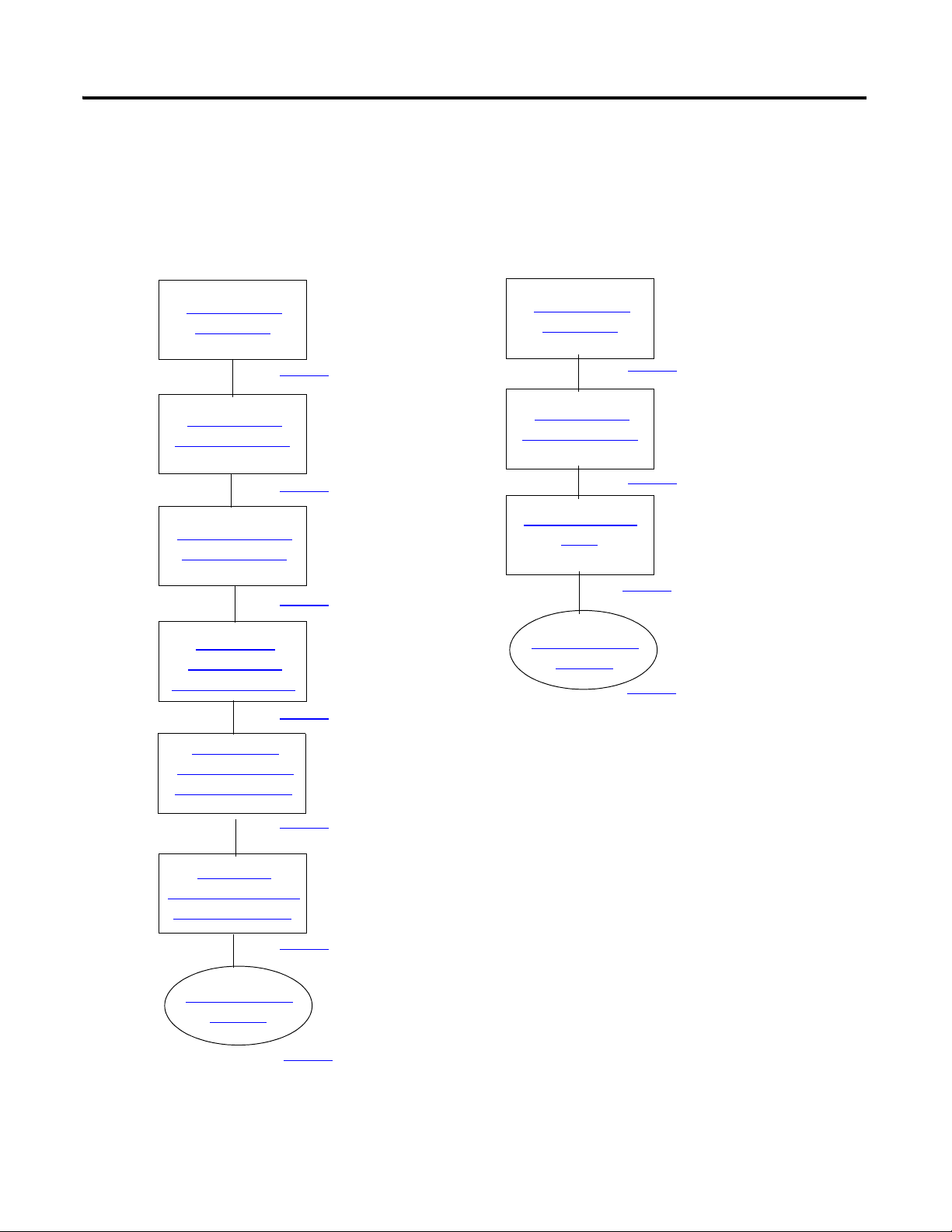
Connect the Battery
to the Packaged
Controller
1769-L23E 1769-L23
Record the
Ethernet Address
(MAC)
Make Network
Connections
Wire Power
Connect the Battery
to the Packaged
Controller
Make Network
Connections
Wire Power
page 25
page 25
page 27
page 26
page 25
page 27
page 26
Follow These Steps
Complete the steps shown for your controller.
24 Publication IASIMP-QS010B-EN-P - October 2009
Page 25
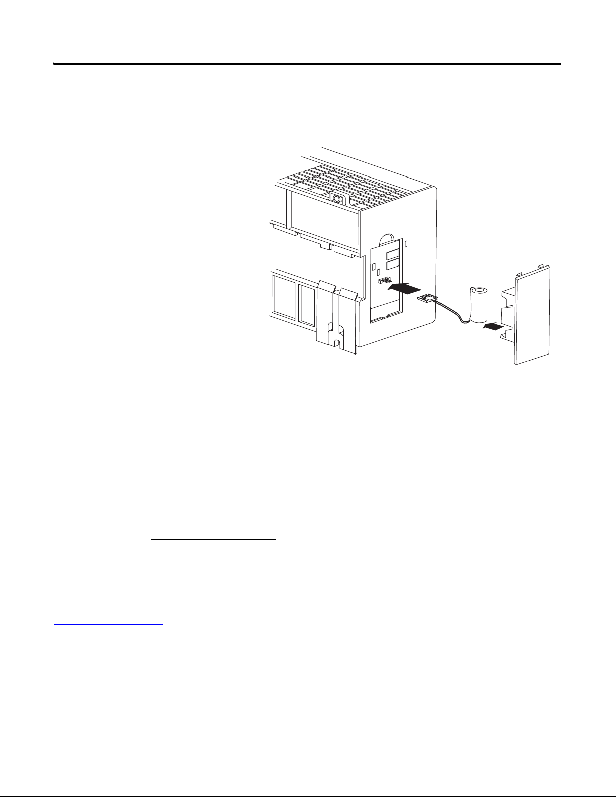
Assemble the CompactLogix Hardware Chapter 1
1. Remove the battery door and
connect the battery to the
controller.
2. Insert the battery into the slot
on the battery door.
3. Close the battery door.
00:00:BC:21:D7:BE
Ethernet Address
Connect the Battery to the Packaged Controller
Battery
Record the Ethernet Address (MAC)
1769-L23E controllers
The Ethernet address (MAC) is found on a label near the power-supply wiring terminal. This
is an example address.
Record the Ethernet address (MAC) for the CompactLogix controller on the
Network Worksheet
address later.
at the back of this quick start. This address may be used to set the IP
Publication IASIMP-QS010B-EN-P - October 2009 25
Page 26
Chapter 1 Assemble the CompactLogix Hardware
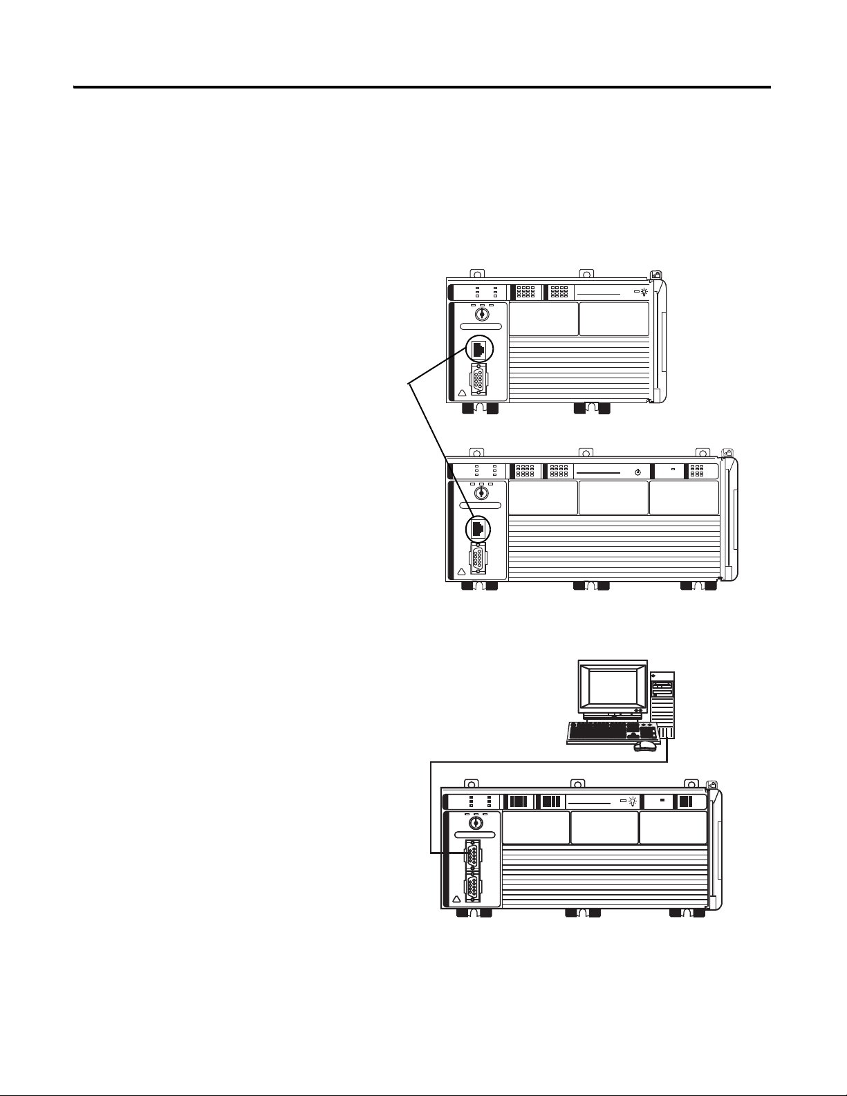
CompactLogix L23E
QBFC-1B
CompactLogix L23E
1. Insert an Ethernet cable with an
RJ45 connector.
2. Connect the other end of the cable
to the Ethernet switch
.
Ethernet Ports
1. Connect the 1756-CP3 cable
to the channel 0 serial port
on the controller.
2. Connect the other end of
the cable to a COM port on
the computer.
CompactLogix L23
1769-L23-QBFC1B
Make Network Connections
1769-L23E packaged controllers, option 1
1769-L23 packaged controllers, option 2
26 Publication IASIMP-QS010B-EN-P - October 2009
Page 27
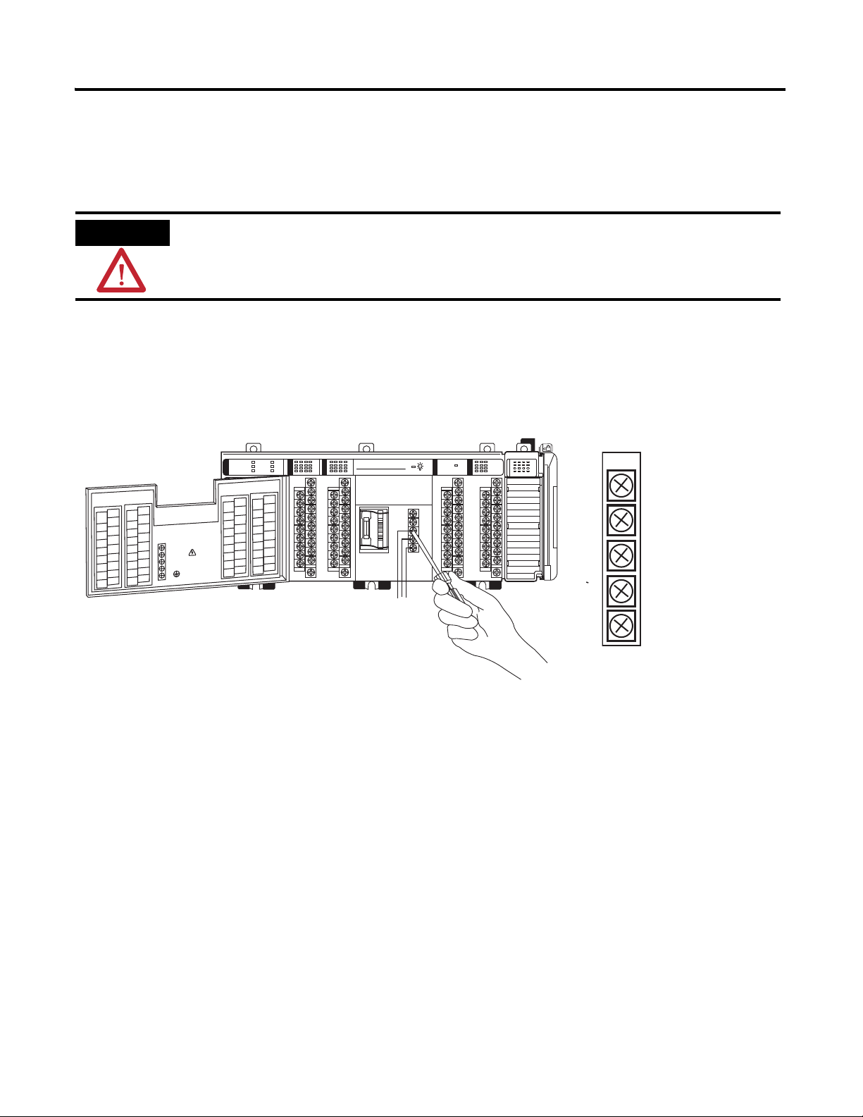
Wire Power
CompactLogix L23E
QBFC-1B
1. Insert the +24V DC, DC neutral, and ground wires and tighten the terminal screws.
2. Turn on incoming power.
WARNING
Verify that all incoming power is turned off before wiring power.
No Connection
+24V DC
DC Neutral
System Power Ground
No Connection
Power supply for all packaged controllers
Assemble the CompactLogix Hardware Chapter 1
Publication IASIMP-QS010B-EN-P - October 2009 27
Page 28

Chapter 1 Assemble the CompactLogix Hardware
Additional Resources
Resource Description
Chapter 6
CompactLogix Packaged Controllers Installation
Instructions, publication 1769-IN082
of the user manual, page 237 Provides detailed information about the use of the 1769-BA with the packaged
controllers.
Provides details about assembling and mounting the controller and upgrading firmware
as well as controller technical specifications.
Publications are available for viewing or electronic download at http://literature.rockwellautomation.com.
28 Publication IASIMP-QS010B-EN-P - October 2009
Page 29

Chapter
2
Prepare the Computer, Network, and Controller
In this chapter, you configure network communication on your computer and install the
necessary programming and configuration software.
In this chapter, you also assign IP addresses to devices on an EtherNet/IP network. For more
information about using the packaged controllers on an EtherNet/IP network, see Chapter 2
of the user manual, titled Network Communication
(page 157).
Before You Begin
• Verify that your computer meets the software’s system requirements for your edition of
RSLogix 5000 software.
What You Need
• RSLogix 5000 software (see the Preface for version and edition information).
• ControlFlash software (packaged with RSLogix 5000 software).
• RLinx Classic software, version 2.54 or later (packaged with RSLogix 5000 software).
• BOOTP/DHCP server utility
• The computer needs a Network Interface Card (NIC) and its associated Windows driver
installed (the NIC and driver are standard on most computers).
• An Ethernet Address (MAC) for each device. You recorded these addresses in the
Network Worksheet
on the back cover.
(packaged with RSLogix 5000 software).
• A planned IP Address for each device. If you are using an isolated network, determine a
numbering convention for your IP addresses. Record these addresses on the
Network Worksheet
29Publication IASIMP-QS010B-EN-P - October 2009 29
inside the back cover.
Page 30
Chapter 2 Prepare the Computer, Network, and Controller
Make Network
Connections
Install RSLogix
5000 Programming
Configure a Serial
Driver
Set the IP Address
for the Computer
Configure the
EtherNet/IP Driver
in RSLinx Software
Install Additional
Software
Browse the
EtherNet/IP Network
in RSLinx Software
page 31
page 40
page 50
page 44
page 45
page 38
page 33
Assign an IP
Address to the
Packaged Controller
page 42
Serial
EtherNet/IP
Make Network
Connections
Install RSLogix
5000 Programming
page 31
page 33
Install Additional
Software
page 50
Optional
Install additional software
specific to your system.
Optional
Install additional software
specific to your system.
Follow These Steps
Complete these steps.
30 Publication IASIMP-QS010B-EN-P - October 2009
Page 31

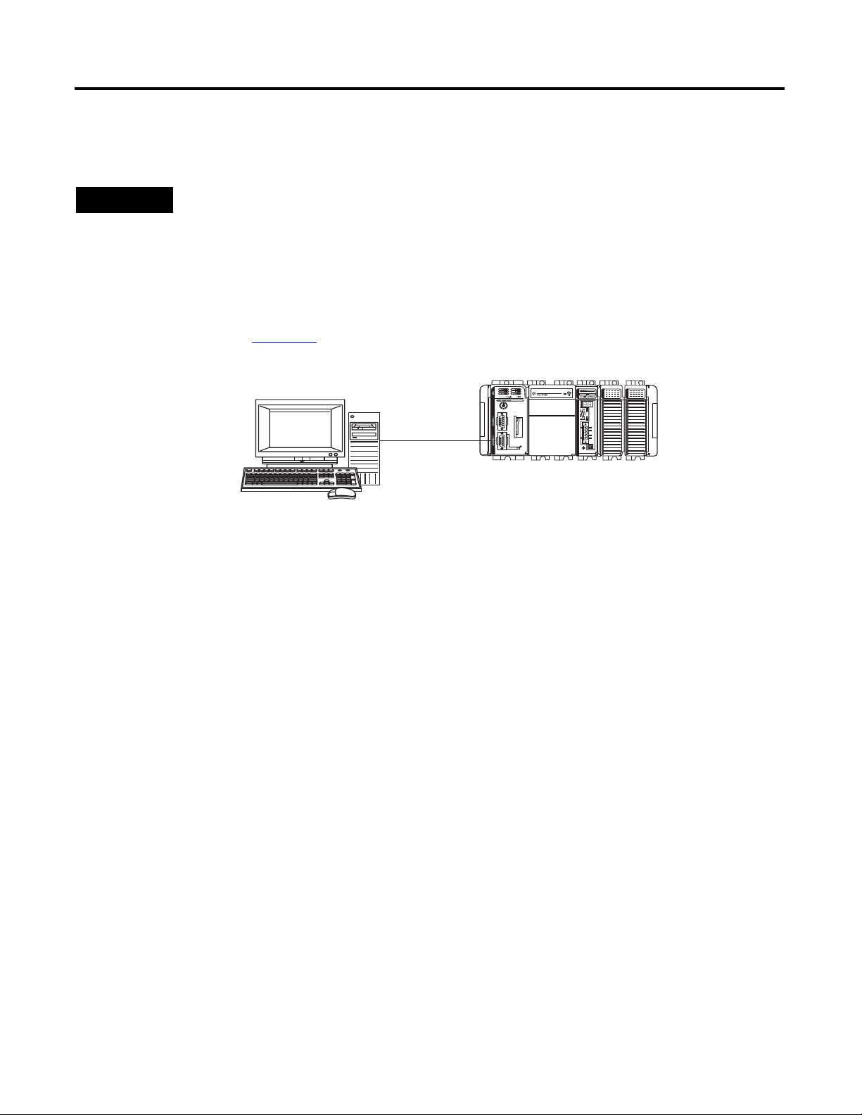
Prepare the Computer, Network, and Controller Chapter 2
1. Connect one end of the
Ethernet cable to the
computer.
2. Connect the other end to the
Ethernet switch
Stratix 6000 Switch
Computer with a standard
Ethernet port.
1769-L23E-QB1B
Terminology
Ethernet networks use these types of addresses.
Term Definition
Ethernet Address Each Ethernet device has a unique Ethernet address (sometimes called a MAC address). The
address appears as twelve digits separated by colons (for example, xx:xx:xx:xx:xx:xx). It is
usually on a label on the device itself.
Each digit is a number in hexadecimal (0 to 9 or A through F). No other device in the world will
have the same address, and it can not be changed.
You use the Ethernet address to identify a device so you can assign it an IP address.
IP Address In addition to the Ethernet address, an IP address identifies a node on an Ethernet network.
The IP address can be manually set. or you can use special software to automatically assign it.
An IP Address consists of four decimal integers separated by periods (xxx.xxx.xxx.xxx). Each xxx
is a decimal value from 0…255. For example, an IP Address could be 192.168.1.092 The
selection of IP Addresses is beyond the scope of this quick start, so please contact your
network administrator or use the ones provided in the examples.
Once you set an IP address for a device, you generally reference the device by its IP address.
The examples in this quick start use IP Addresses to define communication paths to the
devices.
Make Network Connections
Required for option 1
CompactLogix L23E
Publication IASIMP-QS010B-EN-P - October 2009 31
Page 32
Chapter 2 Prepare the Computer, Network, and Controller
TIP
Verify that you connected a 1756-CP3 cable to a COM port on the computer and to the CH0 port on the
controller as described in Chapter 1.
1756-CP3 serial cable to CH0 of an 1769-L23 controller.
This connection will be used to update the controller firmware later in this chapter.
Serial connection - Required for option 2
If you are using an 1769-L23E packaged controller, you may choose to upgrade your controller firmware by
using your Ethernet connection instead. If you use the Ethernet connection, you do not have to make this
serial connection.
32 Publication IASIMP-QS010B-EN-P - October 2009
Page 33

Prepare the Computer, Network, and Controller Chapter 2
3. Accept the default
software products for
installation and click
Next.
Throughout the installation, click Next to use default RSLogix 5000 programming software
installation settings except when indicated in the steps below.
1. Begin the RSLogix
5000 programming
software installation.
2. Choose your language
and click Continue.
4. Enter your user name,
organization, and software serial
number, then click Next.
Install RSLogix 5000 Programming Software
Required for all controllers
Publication IASIMP-QS010B-EN-P - October 2009 33
Page 34
Chapter 2 Prepare the Computer, Network, and Controller
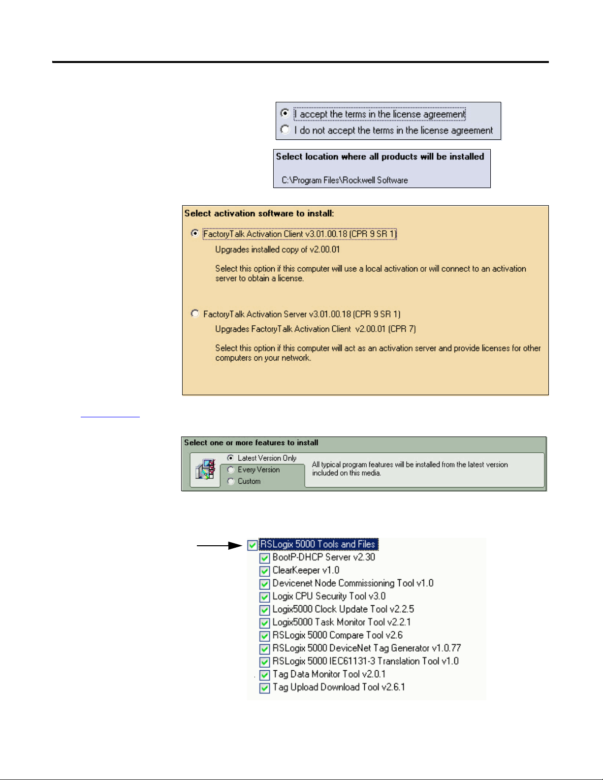
7. Select your
activation type
and click Next.
This quick start uses
FactoryTalk
Activation software
to activate RSLogix
5000 programming
software. For more
information, see the
FactoryTalk
Activation FAQ,
publication
FT00-FA001.
5. Accept the license agreement and
click Next.
8. Click Next to
install only the
latest version of
RSLogix 5000
programming
software (version
17).
9. Verify that
RSLogix 5000
Tools and Files is
checked and click
Next.
6. Click Next to install the program
files to the default directory.
34 Publication IASIMP-QS010B-EN-P - October 2009
Page 35

10. Click Next to
install the typical
firmware kits.
11. Click Next to install
typical RSLogix
Architect tools.
12. Click Next to
install the
typical set of
EDS files and
RSLinx
software.
Prepare the Computer, Network, and Controller Chapter 2
Publication IASIMP-QS010B-EN-P - October 2009 35
Page 36
Chapter 2 Prepare the Computer, Network, and Controller
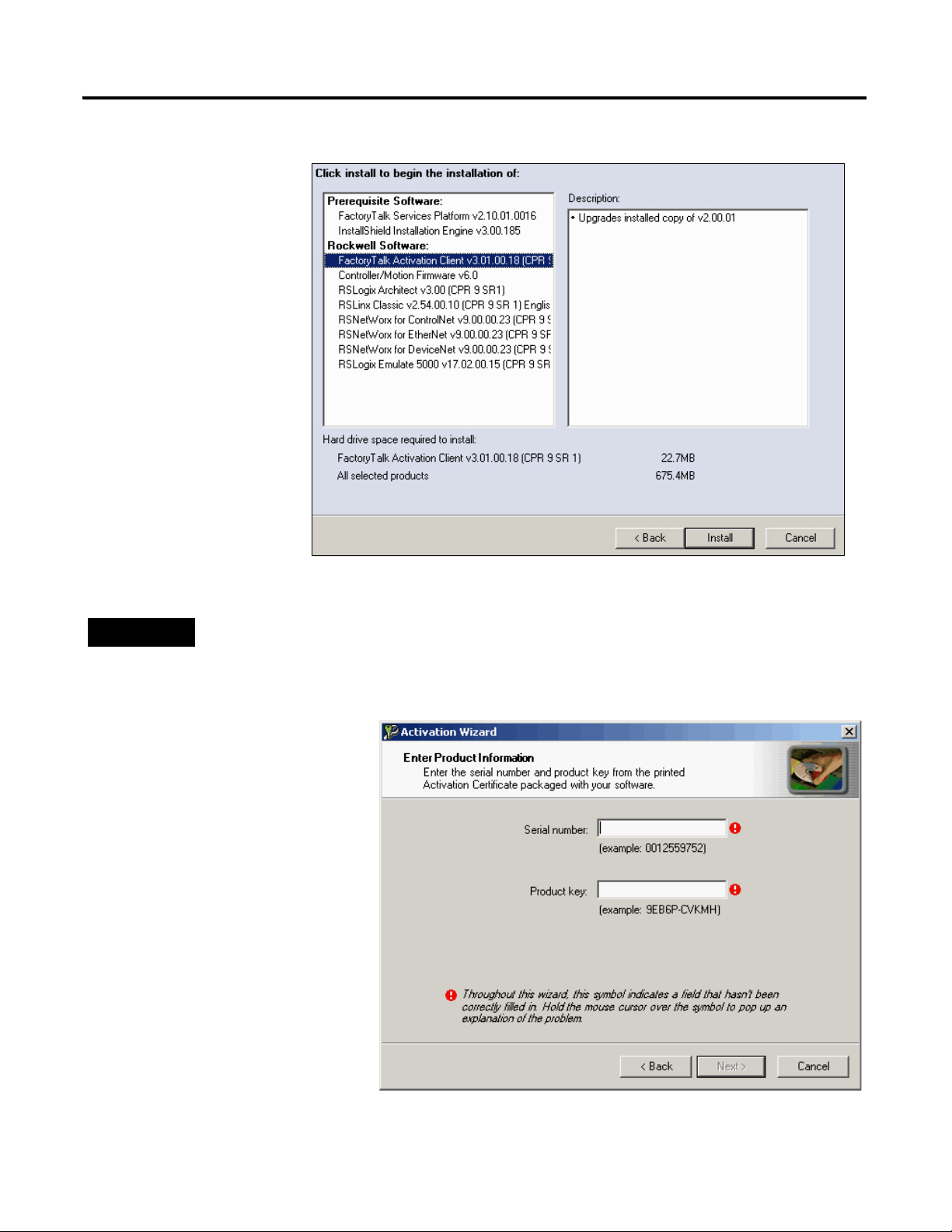
13. Click Install to
complete the
installation.
The installation
dialog box displays
progress while the
software installs.
TIP
As the installation progresses, you may be prompted to complete additional set-up tasks depending on
your system configuration. Follow those prompts and enter information as indicated in the dialog boxes to
complete your installation.
After a few moments, the
FactoryTalk Installation
Wizard starts.
14. Click Next.
15. Enter the Serial number
and Product key from the
certification letter packaged
with your software.
16. Click Next.
36 Publication IASIMP-QS010B-EN-P - October 2009
Page 37
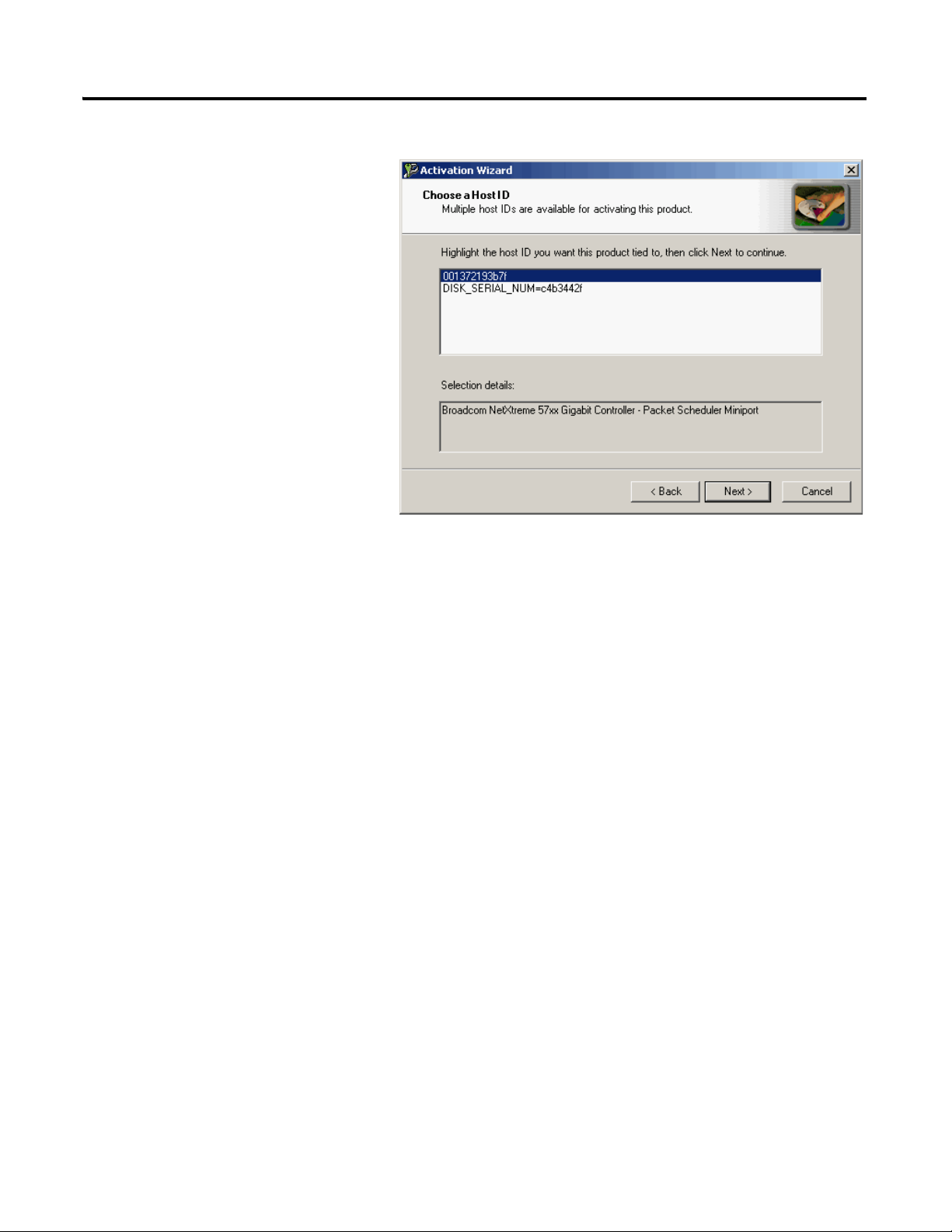
17. Select your host ID and click
Next.
The activation completes if the
computer is connected to the
Internet.
If Internet access is not
available, call Rockwell
Automation Technical
Support to complete your
activation.
18. Click Finish to close the
Activation Wizard.
Prepare the Computer, Network, and Controller Chapter 2
Publication IASIMP-QS010B-EN-P - October 2009 37
Page 38
Chapter 2 Prepare the Computer, Network, and Controller
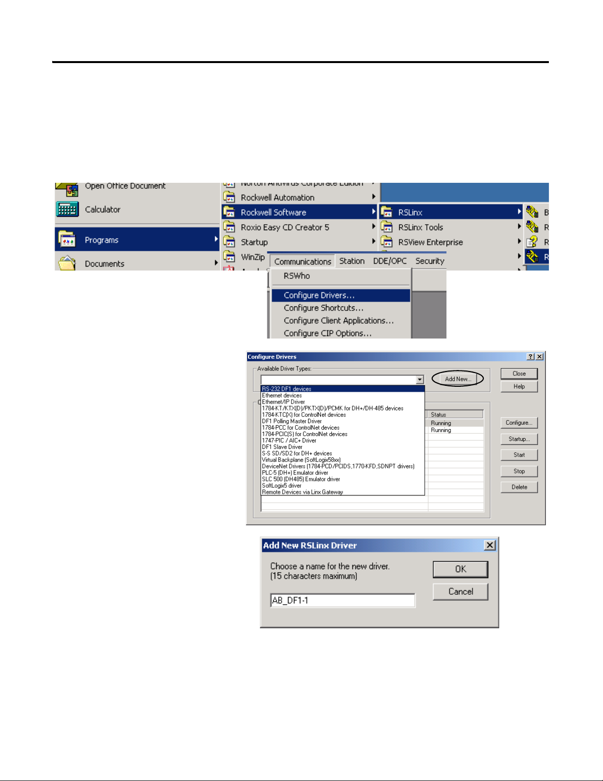
1. Launch RSLinx software.
2. From the Communications menu,
choose Configure Drivers.
3. Select RS-232 DF1
devices.
4. Click Add New.
Configure a Serial Driver
Required for serial network (option 2)
38 Publication IASIMP-QS010B-EN-P - October 2009
Page 39

The Serial driver is added to
the Configured Drivers list.
10. Verify that the Status of the
driver is Running, and click
Close.
11. Click the RSWho icon to
view the driver.
All of the configured, active
drivers display.
6. Select the Comm Port to which you
connected the 1756-CP3 cable.
7. From the Device pull-down, select
Logix5550/CompactLogix.
8. Click Auto Configure.
9. Click OK.
Expand the serial driver to see
connected devices.
Prepare the Computer, Network, and Controller Chapter 2
Publication IASIMP-QS010B-EN-P - October 2009 39
Page 40

Chapter 2 Prepare the Computer, Network, and Controller
1. On your desktop, right-click My
Network Places and choose
Properties.
2. Double-click the Local Area
Connection.
3. Click Properties.
4. On the General tab, select
Internet Protocol
(TCP/IP) and click
Properties.
5. Select Use the following
IP address and enter an IP
address and Subnet mask
for your computer.
6. Click OK.
For more information about selecting an IP Address, see the information on page 31
.
7. Record the IP address and subnet mask in the Network Worksheet
inside the back
cover.
8. Click OK.
Set the IP Address for the Computer
Required for EtherNet/IP network (option1)
40 Publication IASIMP-QS010B-EN-P - October 2009
Page 41

9. Click the Support tab.
10. Verify that the IP Address and Subnet
Mask match what you entered on the
Network Worksheet
.
If these numbers do not match what
you entered, contact your network
administrator to verify that your IP
address is correct.
11. Close the Local Area Connection
Status dialog box.
Prepare the Computer, Network, and Controller Chapter 2
Publication IASIMP-QS010B-EN-P - October 2009 41
Page 42

Chapter 2 Prepare the Computer, Network, and Controller
TIP
Devices on the EtherNet/IP network broadcast requests for IP addresses until the IP addresses have been
assigned.
The procedure in this chapter uses the BOOTP server packaged with RSLogix 5000 programming software
to assign IP addresses, however, any industry-standard BootP server can be used.
1. After you have installed and connected your packaged, launch the BOOTP/DHCP
Server utility.
2. From the Tools menu, choose Network
Settings.
3. Enter the Subnet Mask from the
Network Worksheet
.
4. Click OK.
Assign an IP Address to the Packaged Controller
1769-L23E packaged controllers
In this chapter, you use the BOOTP/DHCP server to assign an IP address to the packaged
controller. You use the BOOTP server that you installed with RSLogix 5000 software.
42 Publication IASIMP-QS010B-EN-P - October 2009
Page 43

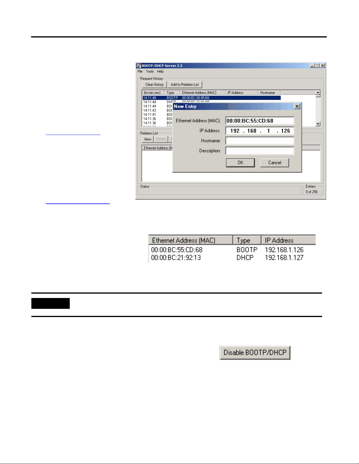
The Request History displays
all the devices, including the
packaged controller, on your
network that need an IP
address. The Ethernet address
(Mac ID) of the packaged
controller corresponds with
the address you recorded on
Network Worksheet.
5. Double-click the request
from your packaged
controller.
6. Enter the IP address and
record it on the
Network Worksheet
inside the
back cover.
If you are not using an isolated
network, obtain these numbers
from your network administrator.
7. Click OK.
8. Disable BootP/DHCP by selecting the packaged controller from the Relation List and
clicking Disable BOOTP/DHCP.
[Disable BOOTP/DHCP] Command successful appears in the Status bar.
9. Close the BOOTP/DHCP Server utility.
If you are prompted to save changes, click No.
IMPORTANT
For a device to retain its IP address through a power cycle, BootP/DHCP must be disabled. Complete step
8 to disable BootP/DHCP for the packaged controller.
IP Addresses Assigned Successfully
Prepare the Computer, Network, and Controller Chapter 2
Publication IASIMP-QS010B-EN-P - October 2009 43
Page 44

Chapter 2 Prepare the Computer, Network, and Controller
1. If RSLinx software is not open, launch RSLinx software.
2. From the Communications
menu, choose Configure
Drivers.
3. From the Available
Driver Types, choose
Ethernet/IP Driver.
4. Click Add New.
5. Click OK to keep the
default name.
6. Click OK to Browse Local
Subnet.
Configure the EtherNet/IP Driver in RSLinx Software
Required for EtherNet/IP network (option 1)
44 Publication IASIMP-QS010B-EN-P - October 2009
Page 45

Prepare the Computer, Network, and Controller Chapter 2
The EtherNet/IP driver is
added to the Configured
Drivers list.
7. Verify that the driver’s
Status is Running, and click
Close.
1. In RSLinx Classic
software, click the
RSWho button.
The EtherNet/IP driver
and network devices
display.
2. Expand the Ethernet
Port and the
backplane to view the
packaged controller.
3. Close or minimize the
RSLinx Classic
window.
Browse the EtherNet/IP Network in RSLinx Software
Publication IASIMP-QS010B-EN-P - October 2009 45
Page 46

Chapter 2 Prepare the Computer, Network, and Controller
1. Launch ControlFlash software.
2. Click Next.
3. Select the controller catalog
number and click Next.
Load Firmware
Required for all packaged controllers
46 Publication IASIMP-QS010B-EN-P - October 2009
Page 47

4. Expand the driver
associated with
your packaged
controller.
5. Select your
packaged
controller.
6. Click OK.
Ethernet
8. If the Current Revision
matches the revision of
firmware you want, click
Cancel and skip to Chapter 3.
Otherwise, select the desired
firmware revision and click
Next.
Packaged
Controller
7. Move the
keyswitch on
the controller
to PROG.
Serial
Prepare the Computer, Network, and Controller Chapter 2
Publication IASIMP-QS010B-EN-P - October 2009 47
Page 48

Chapter 2 Prepare the Computer, Network, and Controller
9. Click Finish and then click
Yes.
The firmware upgrade begins.
IMPORTANT
Do not interupt the firmware
upgrade once it has begun.
Interrupting the firmware upgrade may
result in an inoperable packaged
controller. After the Upgrade Status
dialog box indicates the upgrade is
complete, you may proceed.
10. If updating a 1769-L23E packaged controller, click
OK after reading the release notes.
If using this connection The estimated time to upgrade firmware is
Ethernet 10 min
Serial 40…60 min
1769-L23E Only
48 Publication IASIMP-QS010B-EN-P - October 2009
Page 49
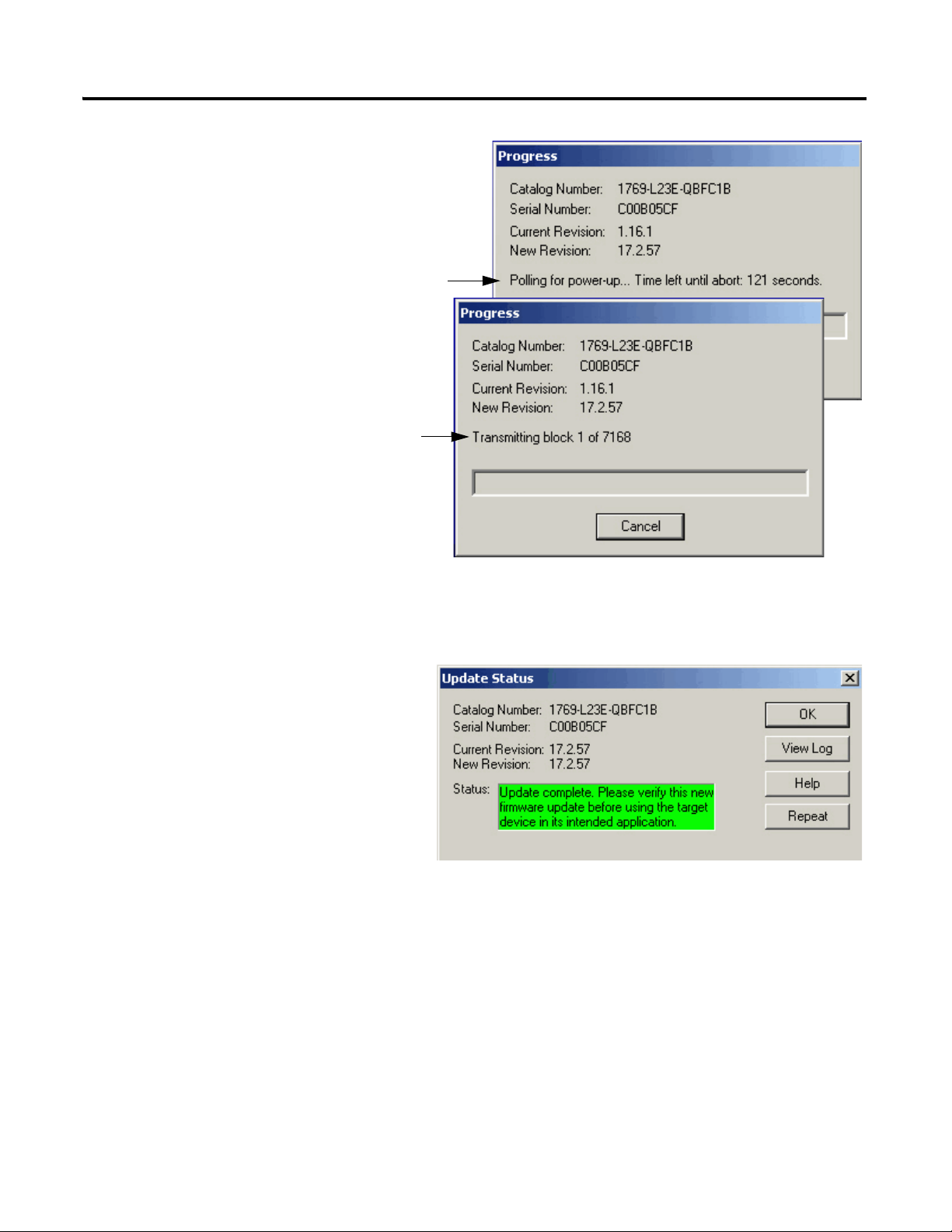
During the firmware
upgrade, these Progress
dialog boxes display 2 or
3 times.
Do not take any action
while these status
dialog boxes display.
These status changes
indicate that the
packaged controller is
self-cycling (Polling for
power-up) and
continuing with the
firmware upgrade
(Transmitting block).
Status change.
Status change.
The Upgrade Status dialog box
indicates that the firmware upgrade
has been successfully completed.
11. Click OK.
12. To close the ControlFlash utility,
click Cancel and then click Yes.
Prepare the Computer, Network, and Controller Chapter 2
Publication IASIMP-QS010B-EN-P - October 2009 49
Page 50

Chapter 2 Prepare the Computer, Network, and Controller
• If you are completing the PanelView Plus chapters in this quick start, install
FactoryTalkView Machine Edition and RSLinx Enterprise software from the
FactoryTalkView Machine Edition package. This software must be installed before you
install any additional software.
• If you are using a DeviceNet network, install RSNetWorx for DeviceNet software.
Install Additional Software
50 Publication IASIMP-QS010B-EN-P - October 2009
Page 51

Additional Resources
Resource Description
Prepare the Computer, Network, and Controller Chapter 2
CompactLogix Packaged Controllers Installation
Instructions, publication 1769-IN082
CompactLogix Packaged Controllers Release
Notes, publication 1769-RN012
FactoryTalk Activation FAQ, publication
FT00-FA001
ControlFlash Firmware Upgrade Kit, publication
1756-QS105
Logix5000 Controllers Quick Start, publication
1756-QS001
EtherNet/IP Modules in Logix5000 Control
Systems, publication ENET-UM001
Provides details about assembling and mounting the controller and upgrading firmware
as well as controller technical specifications.
Provides descriptions of enhancements, anomalies (known and corrected), and
restrictions specific to the firmware revision.
Provides answers to FactoryTalk Activation questions, including how the FactoryTalk
Activation differs from master disk activation.
Provides details regarding the installation of ControlFlash software and execution of
firmware upgrades.
Provides start-up procedures for all Logix5000 controllers with RSLogix 5000 software.
Provides details about using EtherNet/IP modules and devices with RSLogix 5000 and
related software.
Publications are available for viewing or electronic download at http://literature.rockwellautomation.com.
Publication IASIMP-QS010B-EN-P - October 2009 51
Page 52

Chapter 2 Prepare the Computer, Network, and Controller
Notes:
52 Publication IASIMP-QS010B-EN-P - October 2009
Page 53

Chapter
3
Create a Project Using RSLogix 5000 Software
In this chapter you create a project in RSLogix 5000 programming software. In the project
you use ladder logic to create a push button that controls a light on a digital output of the
controller. This project is used in subsequent chapters to test communication with other
devices.
For a programming quick reference and more information about programming your
CompactLogix packaged controller, see Chapter 5
Controller, on page 233.
of the user manual, Program the Packaged
Before You Begin
• Install the required software, see Chapter 2.
• Configure your network, see Chapter 2
.
What You Need
• A CompactLogix packaged controller (1769-L23E-QB1B, 1769-L23-QBFC1B, or
1769-L23E-QBFC1B).
53Publication IASIMP-QS010B-EN-P - October 2009 53
Page 54
Chapter 3 Create a Project Using RSLogix 5000 Software
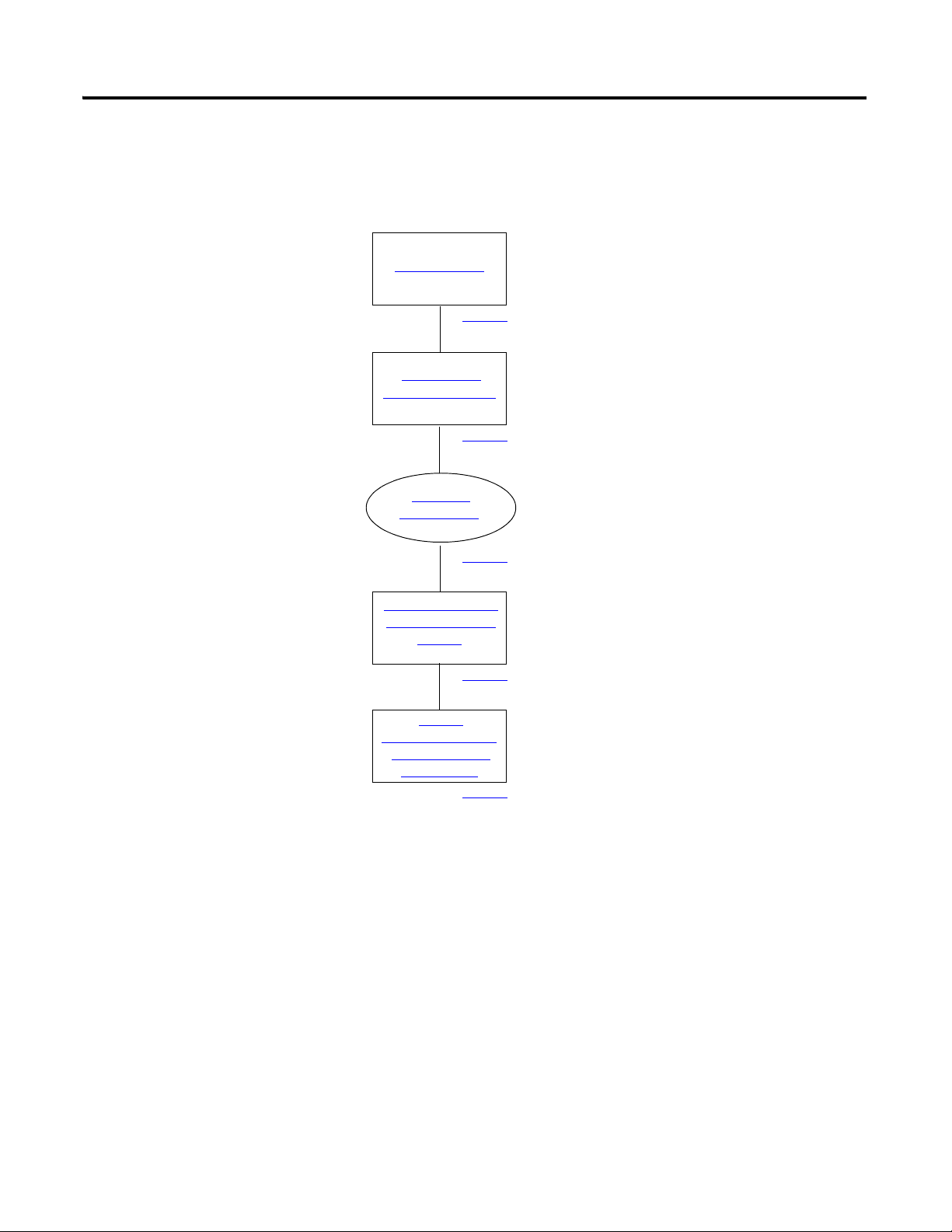
Create a Project
Configure the
Packaged Controller
Configure
Embedded I/O
Add Ladder Logic to
Test the Embedded
Outputs
Set the
Communication Path
and Download to
the Controller
page 55
page 57
page 58
page 59
page 62
Optional
Not required to complete the
examples in this quick start.
Follow These Steps
Complete these steps.
54 Publication IASIMP-QS010B-EN-P - October 2009
Page 55

Create a Project Using RSLogix 5000 Software Chapter 3
1. Open RSLogix 5000 software by clicking Start > Programs > Rockwell Software >
RSLogix 5000 Enterprise Series > RSLogix 5000.
The Quick Start window displays in the RSLogix workspace.
Navigation tabs for
Quick Start, Learning
Center, and Resource
Center pages.
The Quick Start pages provide useful links, tutorials,
training videos, and other tools you may choose to
view before beginning your project.
2. Click New Project.
Create a Project
All controllers
Publication IASIMP-QS010B-EN-P - October 2009 55
Page 56
Chapter 3 Create a Project Using RSLogix 5000 Software
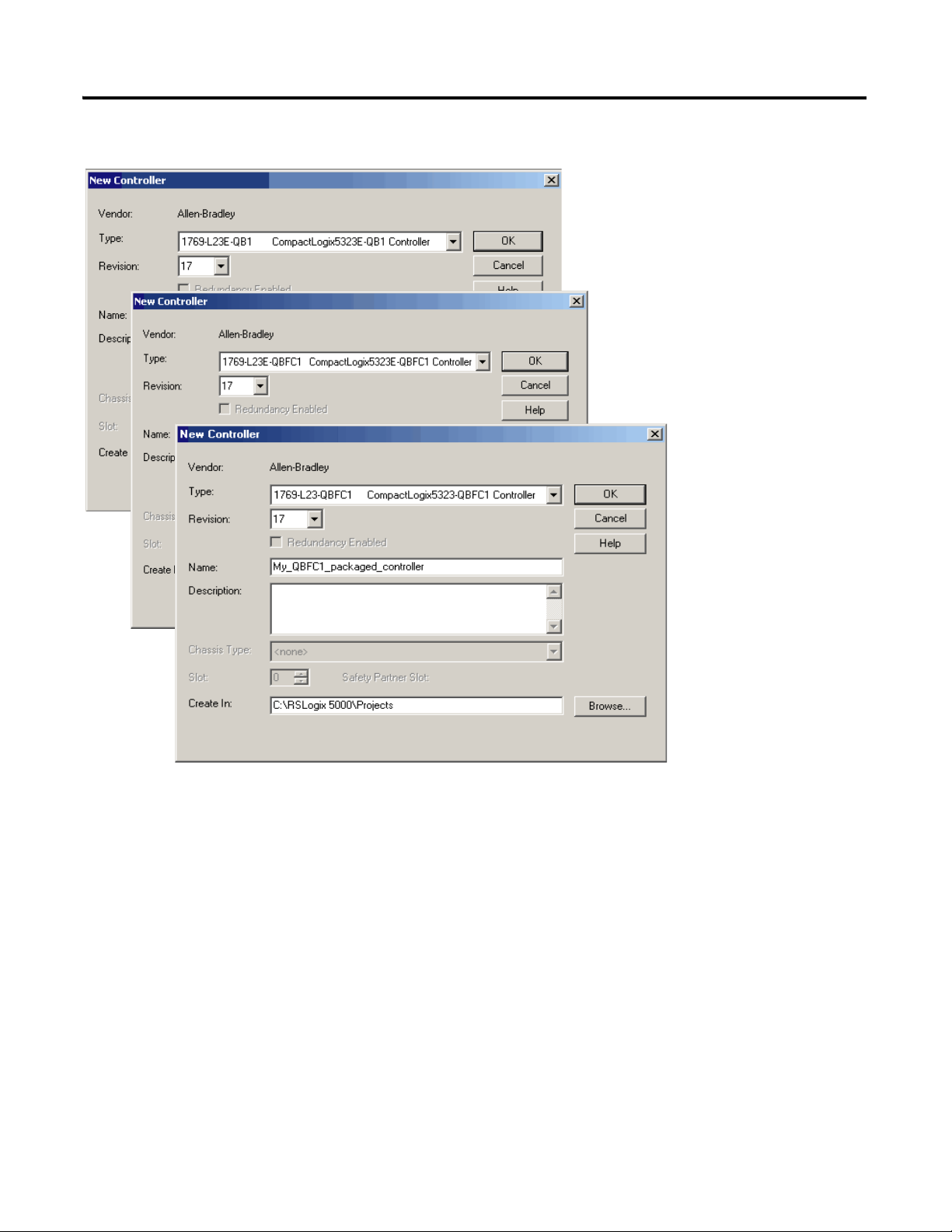
3. Choose your controller and
revision number.
1769-L23E-QB1B
4. Enter a unique controller
name.
5. Click OK.
1769-L23E-QBFC1B
1769-L23-QBFC1B
56 Publication IASIMP-QS010B-EN-P - October 2009
Page 57
Configure the Packaged Controller
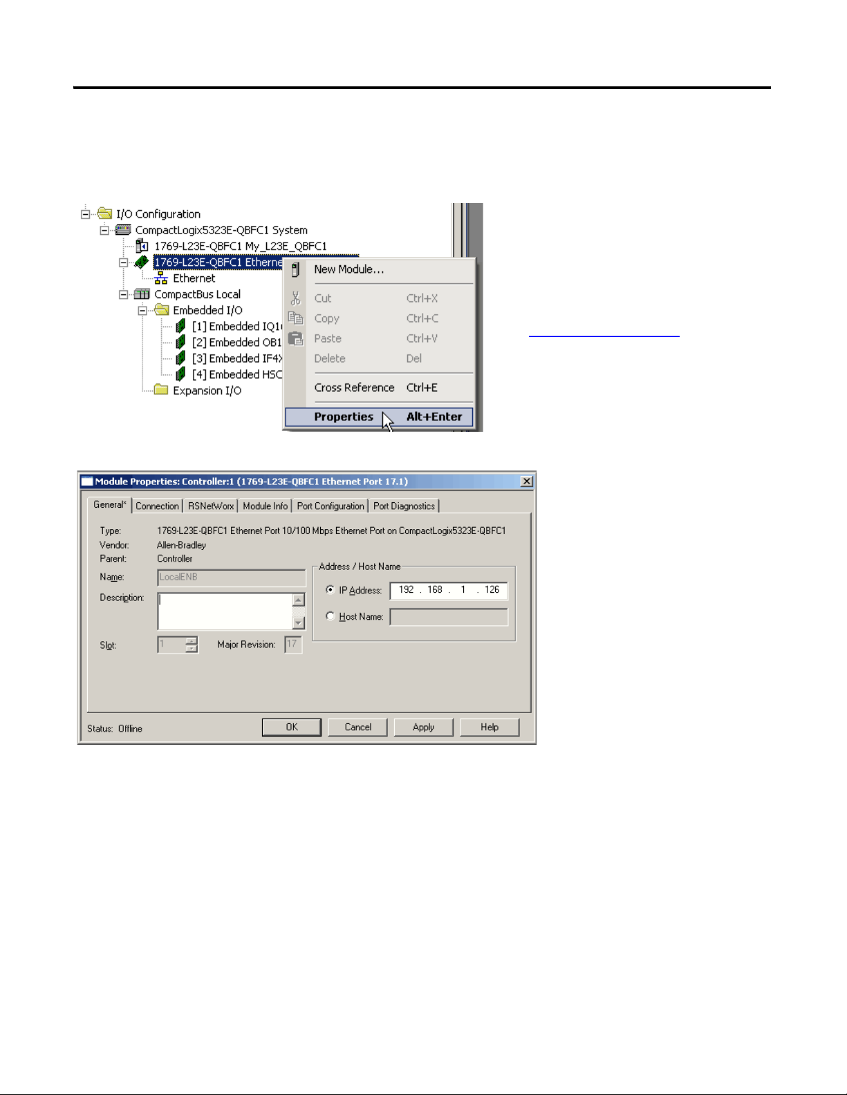
1. Right-click the Ethernet Port
and choose Properties.
2. Enter the controller’s IP
address (recorded on the
Network Worksheet
) and
click OK.
All 1769-L23E controllers
Create a Project Using RSLogix 5000 Software Chapter 3
Publication IASIMP-QS010B-EN-P - October 2009 57
Page 58

Chapter 3 Create a Project Using RSLogix 5000 Software
1. Double-click the embedded I/O you need
to configure.
2. Use the tabs and boxes within the
Module Properties dialog box to specify
your configuration parameters.
For detailed
information about
configuring your
embedded I/O, see
Chapter 3 of the user
manual, Embedded
I/O (page 191).
Configure Embedded I/O
Not required for quick start examples
The quick start examples use the default configuration of the embedded I/O. Before you use
the embedded I/O in your application, you may choose to configure the embedded I/O
specific to your application.
58 Publication IASIMP-QS010B-EN-P - October 2009
Page 59

Add Ladder Logic to Test the Embedded Outputs
1. Expand the Tas ks folders and
double-click MainRoutine.
A blank MainRoutine opens.
2. From the Element Toolbar, drag and drop an Examine On and an
Output Energize element onto the rung.
All controllers
Create a Project Using RSLogix 5000 Software Chapter 3
Publication IASIMP-QS010B-EN-P - October 2009 59
Page 60

Chapter 3 Create a Project Using RSLogix 5000 Software
3. Double-click the ? in the
Examine On.
4. Type PB (for push button).
5. Press Enter.
6. Right-click PB and choose New
‘PB’.
7. Click OK to keep the defaults.
60 Publication IASIMP-QS010B-EN-P - October 2009
Page 61

9. Right-click the Output_Light tag name and
choose New ‘Output_Light’.
Output_Light is an alias tag for the I/O point
tag name. This lets you assign a simple name to
a physical I/O point address.
10. From the Type pull-down menu,
select Alias.
11. In the Alias For pull-down menu,
browse to a local output point and
select any bit.
In this example, Local:2:O.Data.0 is
used.
12. Click OK.
The output shows the specified
output.
8. Name the Output Energize Output_Light.
IMPORTANT
Do not use spaces in the tag name. Use
underscores ( _ ) instead.
Create a Project Using RSLogix 5000 Software Chapter 3
Publication IASIMP-QS010B-EN-P - October 2009 61
Page 62

Chapter 3 Create a Project Using RSLogix 5000 Software
4. Expand the network
tree.
5. Select your controller
and click Set Project
Path.
6. Click Download.
1. Save your changes.
3. Click the RSWho
button.
EtherNet/IP
Serial
2. Move the keyswitch on your controller to Program.
Set the Communication Path and Download to the Controller
All 1769-L23 controllers
62 Publication IASIMP-QS010B-EN-P - October 2009
Page 63

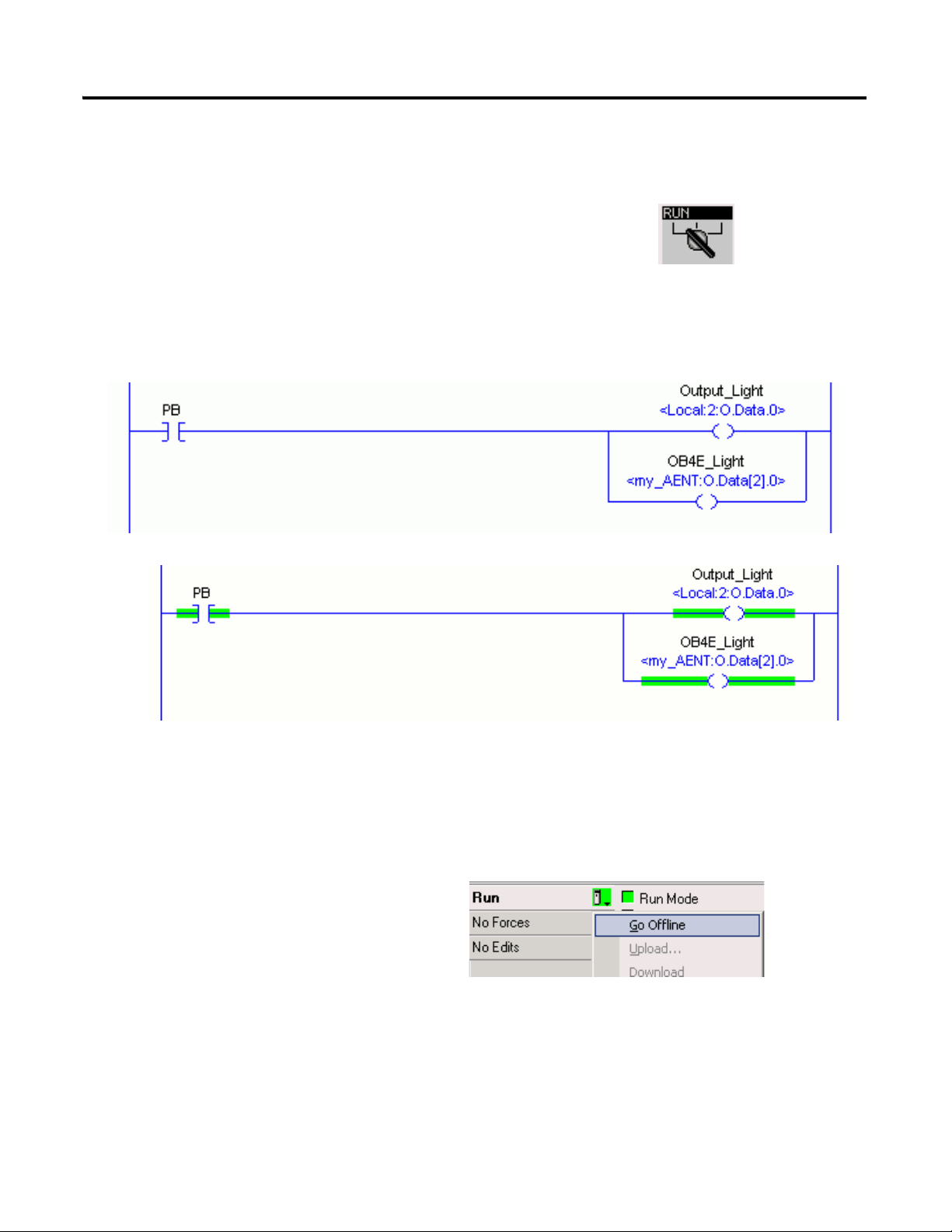
8. Move the keyswitch on your controller to Run.
9. Select the PB Examine On instruction and press Ctrl+T.
This toggles the state from 0 to 1 (off to on).
10. Verify that the LED indicator on the digital output of the
controller turns on.
11. Press Ctrl+T to toggle the state back to 0 (off).
12. Go Offline.
Off
On
The project Path updates.
EtherNet/IP
7. Click Download.
Serial
Create a Project Using RSLogix 5000 Software Chapter 3
Publication IASIMP-QS010B-EN-P - October 2009 63
Page 64

Chapter 3 Create a Project Using RSLogix 5000 Software
Additional Resources
Resource Description
Chapter 5
Packaged Controller, on page 233
Logix5000 Controllers Common Procedures
Programming Manual, publication 1756-PM001
of the user manual, Program the
Provides detail information about programming the packaged controllers, including
available user memory, available programming languages, use of programs and
equipment phases, and monitoring controller status.
Provides details about creating and editing a program, communicating with modules,
and configuring modules.
These manuals are available for viewing or electronic download at http://literature.rockwellautomation.com.
64 Publication IASIMP-QS010B-EN-P - October 2009
Page 65

Chapter
4
Add POINT I/O
In this chapter, you install the 1734 POINT I/O network adapter and the 1734 POINT I/O
modules. You then add POINT I/O modules to your project using RSLogix 5000
programming software. You also add ladder logic and download the project to the controller
so you can test communication with an I/O module. This project builds upon the program
created in Chapter 3
Before You Begin
.
• Create a project in RSLogix 5000 programming software, see Chapter 3.
• Select the appropriate mounting base for I/O modules:
– if you use a 1734-IT2I module, then use the 1734-TBCJC.
– for all other I/O modules, use the 1734-TB or 1734-TBS.
What You Need
• POINT I/O adapter: 1734-AENT for Ethernet./IP network.
• POINT I/O mounting bases: 1734-TB or 1734-TBS, and 1734-TBCJC.
• A digital-output POINT I/O module. The examples use a 1734-OB4E.
• Power supply: 1794-PS3 or 1794-PS13.
• This chapter also uses the 1734-IB4 module as an example, however, use of the module
is not required.
65Publication IASIMP-QS010B-EN-P - October 2009 65
Page 66

Chapter 4 Add POINT I/O
Add Ladder Logic
page 76
Download the
Project
page 78
Test the POINT I/O
Light
page 80
Add POINT I/O
Modules to the
Project
page 73
Mount and Connect
the Network
Adapter
Mount the POINT
I/O Modules
Mount and Wire the
POINT I/O Power
Supply
Assign an IP
Address to the
POINT I/O Adapter
page 67
page 69
page 68
page 71
Set the POINT I/O
Chassis Size
page 79
Follow These Steps
If you are using POINT I/O modules, complete these steps.
66 Publication IASIMP-QS010B-EN-P - October 2009
Page 67

Mount and Connect the Network Adapter
1. Locate the Ethernet address (MAC), found
next to the label. Record the Ethernet address
(MAC) for the POINT I/O adapter on the
Network Worksheet
.
This address is used to set the IP address later
in the quick start.
2. Set the address to a value greater than or
equal to 256.
This example uses 999.
3. Remove the safety end cap.
4. Press the adapter onto the DIN rail.
5. Insert an Ethernet cable.
00:00:BC:21:8A:B6
Ethernet Address
Example Address
(Found on the right side of the module.)
Ethernet Port
EtherNet/IP network
Add POINT I/O Chapter 4
Publication IASIMP-QS010B-EN-P - October 2009 67
Page 68
Chapter 4 Add POINT I/O
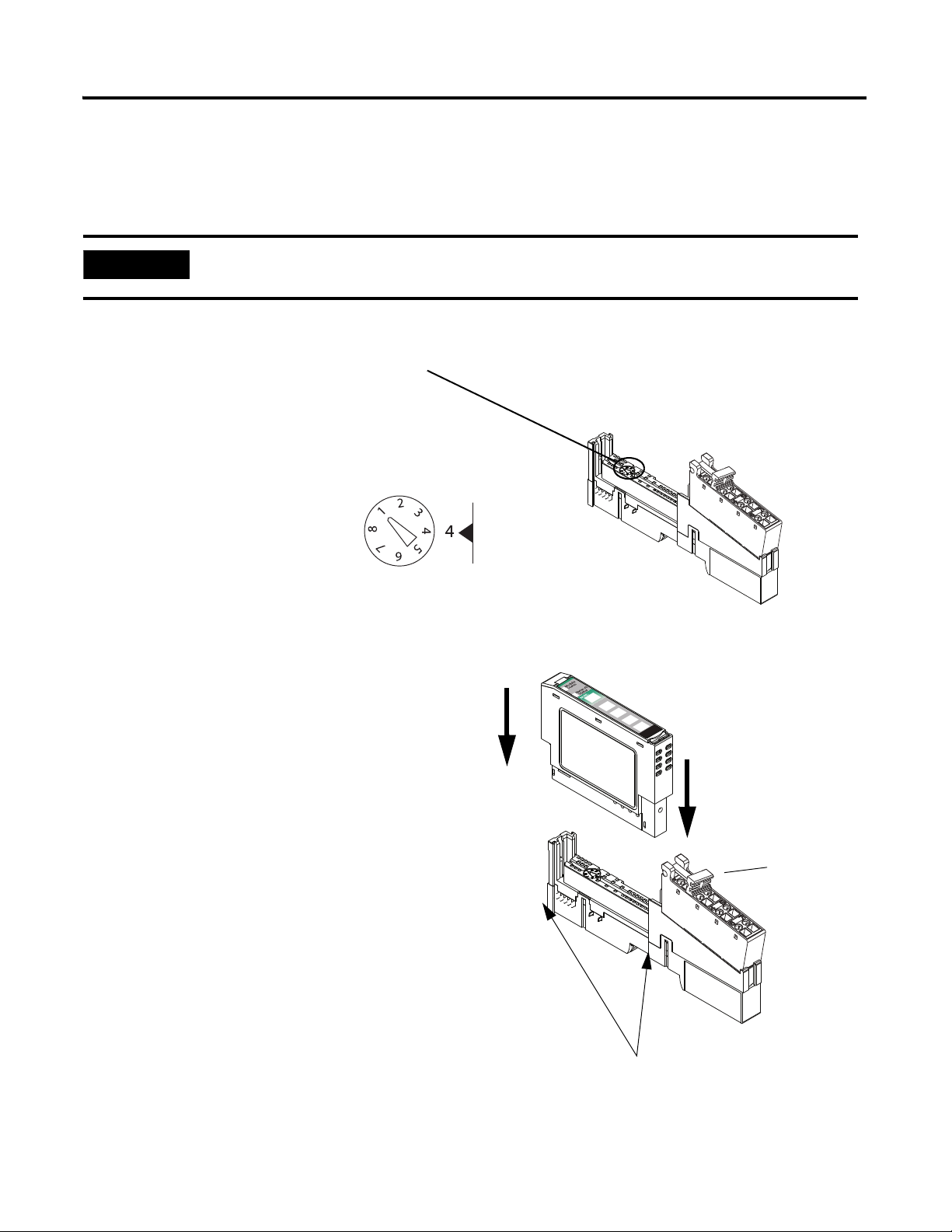
1. Using a small, flathead screwdriver, rotate the
keyswitch to match the figure on the I/O
module.
2. Press the module into the wiring base.
3. Snap the handle up.
4. Complete steps 1–3 with all POINT I/O
modules.
5. Slide the first module and wiring base
assembly along the adapter and press it
onto the DIN rail.
6. Repeat with all of the I/O assemblies.
Handle
Tongue-and-groove Slots
IMPORTANT
The 1734-IT2I module must be mounted in the 1734-TBCJC wiring base. All other modules can be
mounted in either of the 1734-TB or 1734-TBS wiring bases.
Figure on Module
Wiring Base
Module
Mount the POINT I/O Modules
All controllers, POINT I/O modules, and wiring bases
68 Publication IASIMP-QS010B-EN-P - October 2009
Page 69
Mount and Wire the POINT I/O Power Supply
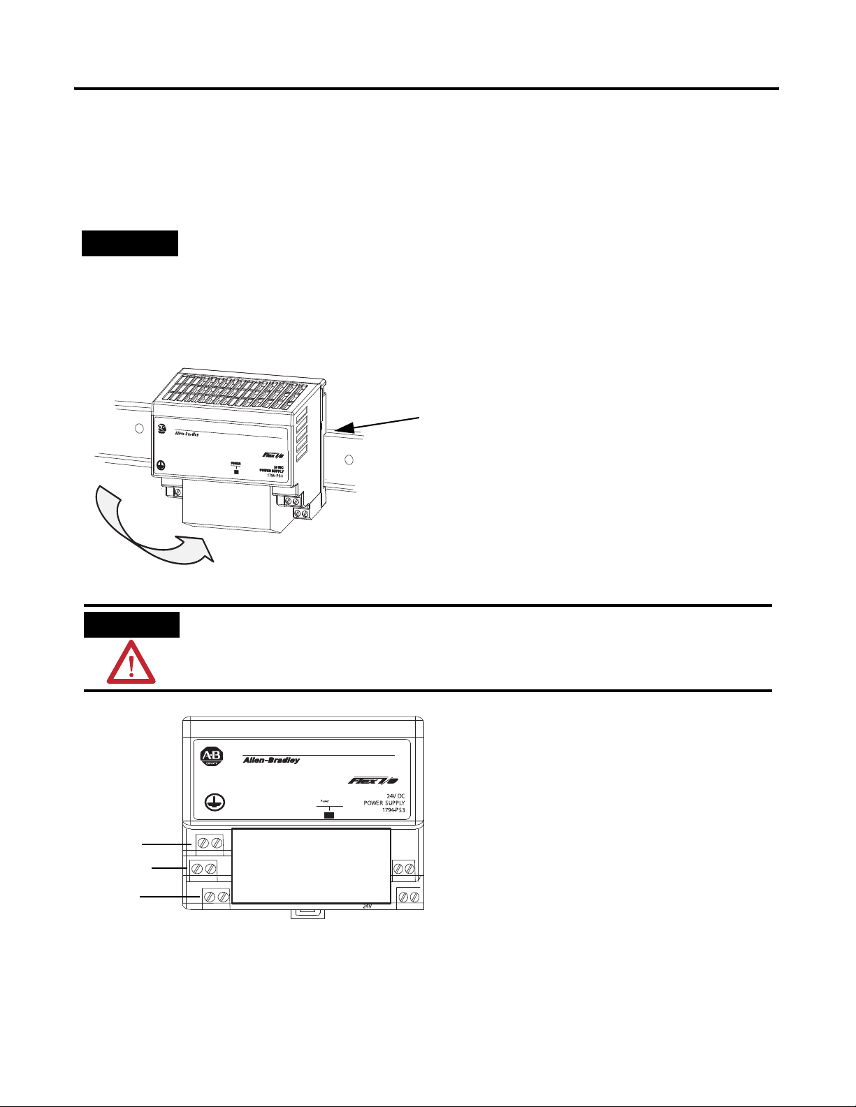
1. Hook the upper-lip of the DIN rail latch onto the
DIN rail.
2. Press the module onto the DIN rail.
3. Connect the 120/230V AC power,
120/230V AC common and AC
Ground wires.
Ground
Common
Power
WARNING
Verify that all incoming power is turned off before wiring power.
Upper-lip of DIN-rail latch.
TIP
You can choose to power your POINT I/O with the listed POINT I/O power supplies, or, use the DC power
supply powering your packaged controller. Any 24V DC power supply can be used with the POINT I/O.
Verify that any power supply you use is disconnected before wiring power.
1794-PS3 or 1794-PS13 power supplies
Add POINT I/O Chapter 4
Publication IASIMP-QS010B-EN-P - October 2009 69
Page 70

Chapter 4 Add POINT I/O
Common
Power
1. Connect the 12/24V DC common
and 12/24V DC power wires from
the power supply to the adapter.
2. Refer to the individual POINT
I/O installation instructions for
wiring the I/O modules.
3. Turn on incoming power.
Wire the Adapter and I/O Modules to the Power Supply
POINT I/O adapter, I/O modules, and power supply
70 Publication IASIMP-QS010B-EN-P - October 2009
Page 71

Add POINT I/O Chapter 4
TIP
Devices on the EtherNet/IP network broadcast requests for IP addresses until the IP addresses have been
assigned.
The procedure in this chapter uses the BOOTP server packaged with RSLogix 5000 software to assign
IP addresses, however, any industry-standard BootP server can be used.
1. After you have installed and connected your adapter, launch the BOOTP/DHCP
Server utility.
2. From the Tools menu, choose Network
Settings.
3. Enter the Subnet Mask from the
Network Worksheet
.
4. Click OK.
Assign an IP Address to the POINT I/O Adapter
EtherNet/IP network
In this chapter, you use the BOOTP/DHCP server to assign an IP address to the POINT
I/O adapter. You use the BootP server that was installed with RSLogix 5000 programming
software.
Publication IASIMP-QS010B-EN-P - October 2009 71
Page 72
Chapter 4 Add POINT I/O
The Request History displays
all the devices, including the
packaged controller, on your
network that need an IP
address. The Ethernet address
(MAC ID) of the adapter
corresponds with the address
you recorded on
Network Worksheet.
5. Double-click the request
from your adapter.
6. Enter the IP address and
record it on the
Network Worksheet
inside
the back cover.
If you are not using an isolated
network, obtain these numbers
from your network
administrator.
7. Click OK.
8. To disable BootP/DHCP, select the adapter from the Relation List and click Disable
BOOTP/DHCP.
[Disable BOOTP/DHCP] Command successful
appears in the Status bar.
9. Close the BOOTP/DHCP Server utility.
If you are prompted to save changes, click No.
IMPORTANT
For a device to retain its IP address through a power cycle, BootP/DHCP must be disabled. Complete step
8 to disable BootP/DHCP for the adapter.
IP Addresses Assigned Successfully
72 Publication IASIMP-QS010B-EN-P - October 2009
Page 73
Add POINT I/O Modules to the Project
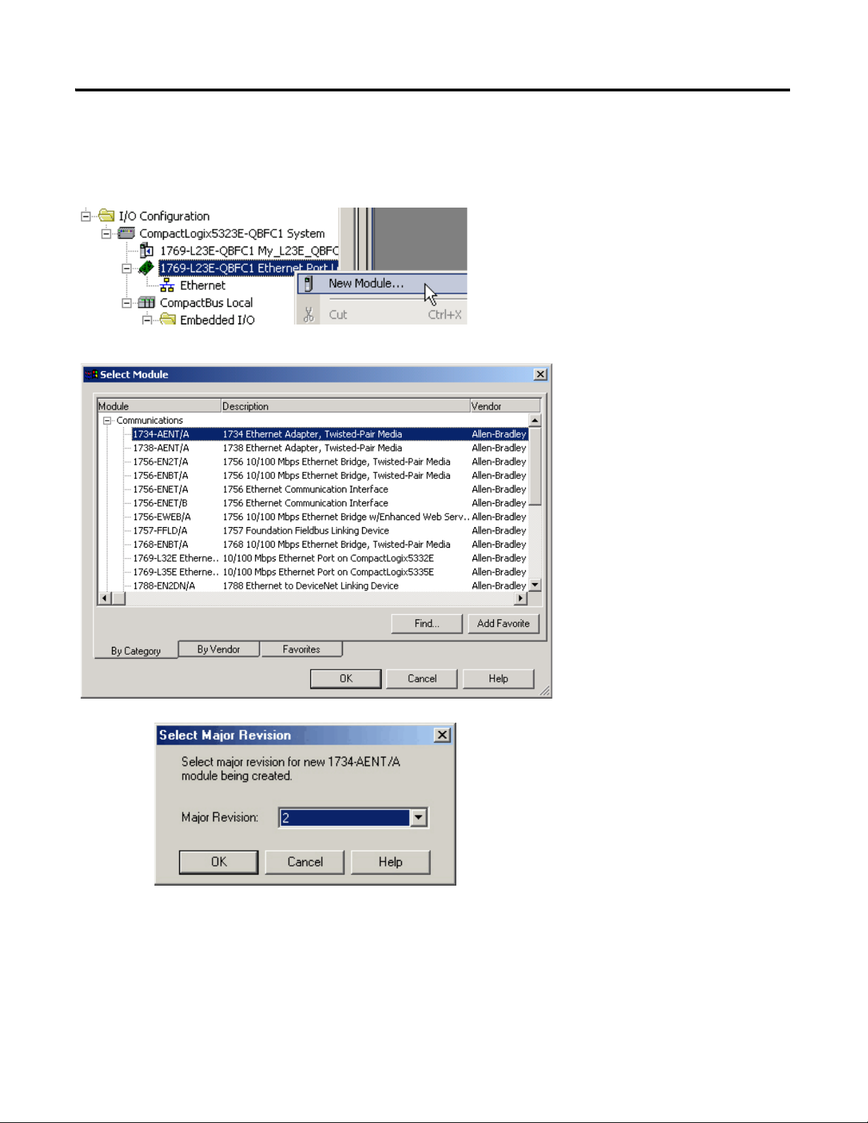
3. Select the 1734-AENT
POINT I/O network adap
and click OK.
1. Verify that your project is
Offline.
2. Right-click the network port
and choose New Module.
4. Specify the major revision
and click OK.
Module Properties dialog
box opens.
Add POINT I/O Chapter 4
Publication IASIMP-QS010B-EN-P - October 2009 73
Page 74

Chapter 4 Add POINT I/O
5. Type a name for the
adapter.
6. Type the IP address.
Use the
Network Worksheet
located inside the back
cover as a reference.
7. Select the Chassis
Size (exact number of
POINT I/O modules
+ 1 for the adapter).
8. Verify that Open
Module Properties is
unchecked and click
OK.
The adapter is added to the
I/O configuration.
9. Right-click the 1734 POINT
network adapter module and
choose New Module.
74 Publication IASIMP-QS010B-EN-P - October 2009
Page 75

11. Enter a name.
12. Click OK.
10. Select the left-most
POINT I/O module
in your chassis and
click OK.
The module is added to the I/O
Configuration.
13. Repeat steps 9…12 until all of your
POINT I/O modules are added in
order from left to right.
After you have completed adding your
POINT I/O modules, go to Add Ladder
Logic on page 76
.
Completed Configuration of POINT I/O Modules
Add POINT I/O Chapter 4
Publication IASIMP-QS010B-EN-P - October 2009 75
Page 76

Chapter 4 Add POINT I/O
1. In the Main Routine, drag and drop a Branch onto the rung.
2. Expand the branch to the right side of Output _Light.
3. Drag and drop another Output Energize element
onto the Branch and name it xxxx_Light
(where xxxx identifies your output module).
Add Ladder Logic
76 Publication IASIMP-QS010B-EN-P - October 2009
Page 77

5. From the Type pull-down, choose
Alias.
6. From the Alias For pull-down
menu, browse to find your 1734
output module.
7. Click the output point you want to
use.
8. Click OK.
9. Click Save.
4. Right-click the Light and choose
New ‘xxxx_Light’.
Add POINT I/O Chapter 4
Publication IASIMP-QS010B-EN-P - October 2009 77
Page 78

Chapter 4 Add POINT I/O
3. Click Download.
If you have no loads wired to your
output modules, the red status
LEDs indicators may start
blinking.
2. Click the Controller Status icon
and choose Download.
If you are using an EtherNet/IP network, after you download to the controller, the
1734 modules may show faults. Setting the chassis size as shown in the next section
should resolve these faults.
1. Move the keyswitch on your controller to Program.
Download the Project
78 Publication IASIMP-QS010B-EN-P - October 2009
Page 79

Set the POINT I/O Chassis Size
1. Right-click the 1734-AENT and
choose Properties.
If the both the chassis sizes match, skip to step 1
on page 80
.
If the numbers do not match, continue with step 3.
3. On the Connection tab, check the Inhibit Module
checkbox and click Apply.
4. Click Yes.
2. Click the Chassis
Size tab.
Set Chassis Size in Module.
6. Click OK at the warning.
The Module chassis size updates.
7. On the Connection Tab, uncheck the Inhibit
Module checkbox and click OK.
8. Click Yes.
You have set the POINT I/O chassis size.
9. Click Save.
5. On the Chassis size tab, click
Add POINT I/O Chapter 4
Publication IASIMP-QS010B-EN-P - October 2009 79
Page 80
Chapter 4 Add POINT I/O
1. Move the keyswitch on your controller to RUN.
2. Select the PB and press Ctrl+T.
This toggles the state from 0 to 1 (off to on).
3. Verify that the lights on both the embedded and POINT digital output modules turn
on.
4. Press Ctrl+T to toggle the state back to 0 (off).
5. Choose Go Offline.
Off
On
Test the POINT I/O Light
80 Publication IASIMP-QS010B-EN-P - October 2009
Page 81

Additional Resources
Resource Description
Add POINT I/O Chapter 4
Point I/O Ethernet Adapter Installation
Instructions, publication 1734-IN590
1734 Point I/O ControlNet Adapter Installation
Instructions, publication 1734-IN582
Point I/O DeviceNet Adapter Installation
Instructions, publication 1734-IN026
POINT I/O Wiring Base Assembly Installation
Instructions, publication 1734-IN511
Cold Junction Compensated Terminal Block
Installation Instructions, publication
1734-IN583
Point I/O Protected Output Module Installation
Instructions, publication 1734-IN056
FLEX I/O DC Power Supply Modules Installation
Instructions, publication 1794-IN069
ControlLogix Controllers Common Procedures
Programming Manual, publication 1756-PM001
Provides details regarding installation of the adapter and technical specifications.
Provides details regarding installation of the adapter and technical specifications.
Provides details regarding installation of the adapter and technical specifications.
Provides details regarding installation of the POINT I/O wiring base.
Provides details regarding installation of the Cold Junction Compensated Terminal
Block wiring base.
Provides details about the installation and wiring of POINT I/O Protected Output
Modules.
Provides details about the installation and wiring of FLEX I/O power supplies.
Provides details about adding and configuring modules, establishing communication,
and writing ladder logic.
Publications are available for viewing or electronic download at http://literature.rockwellautomation.com.
Publication IASIMP-QS010B-EN-P - October 2009 81
Page 82

Chapter 4 Add POINT I/O
Notes:
82 Publication IASIMP-QS010B-EN-P - October 2009
Page 83

Chapter
5
Add a PowerFlex 40 Drive
In this chapter, you mount and wire power to a PowerFlex 40 drive, configure your
communication adapter, and make network connections. You then configure a PowerFlex 40
drive using the drive keypad and add the drive to your project using RSLogix 5000
programming software. This project builds upon the project created in Chapter 3
Before You Begin
• Create a project using RSLogix 5000 programming software, see Chapter 3.
What You Need
• PowerFlex 40 drive
• Communication adapter for use with the PowerFlex 40 drive (22-COMM-E,
EtherNet/IP adapter)
• Communication adapter cover for use with the PowerFlex 40 drive
• No additional software required
.
83Publication IASIMP-QS010B-EN-P - October 2009 83
Page 84

Chapter 5 Add a PowerFlex 40 Drive
Add the Drive to
the Project
page 90
Download the
Project
page 92
Edit PowerFlex 40
Parameter Values
page 93
Test the PowerFlex
40 Tags
page 95
Assign an IP Address
to the PowerFlex 40
Drive
page 88
Mount the
PowerFlex 40 Drive
Wire Power
Connect the
Communication
Adapter
page 85
page 85
page 86
Follow These Steps
If you have a PowerFlex 40 drive, complete these steps for your network.
84 Publication IASIMP-QS010B-EN-P - October 2009
Page 85
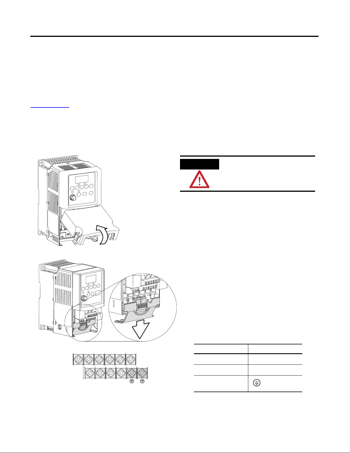
Add a PowerFlex 40 Drive Chapter 5
1. Remove the cover.
V/T2T/L3S/L2R/L1 U/T1 W/T3
BR+ BR-DC- DC+
2. Remove the terminal block cover to
access the power connections.
3. Insert the 120/240V AC, V AC COM
and chassis ground wires and tighten
the terminal screws.
Connect To
120/240V AC
R/L1
V AC COM
S/L2
Chassis ground
WARNING
Verify that all incoming power
is turned off before wiring
power.
Mount the PowerFlex 40 Drive
For this quick start, the PowerFlex 40 drive is simply placed on a desktop.
For complete mounting instructions, see the PowerFlex 40 Drive User Manual, publication
22B-UM001
.
Wire Power
Publication IASIMP-QS010B-EN-P - October 2009 85
Page 86
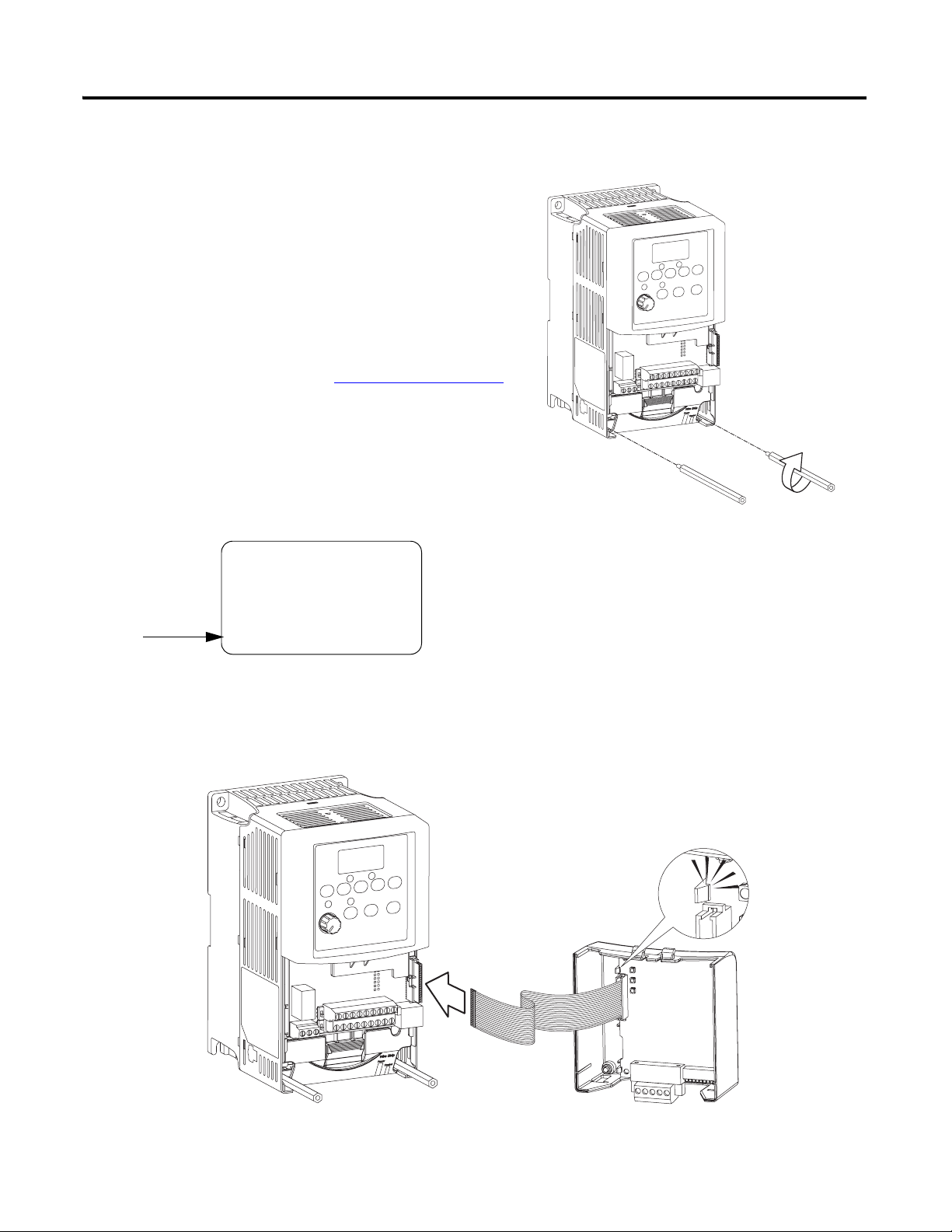
Chapter 5 Add a PowerFlex 40 Drive
1. Record the Ethernet address (MAC ID) of the
Ethernet adapter on the Network Worksheet
.
The Ethernet address is found on the label on
the back of the Ethernet adapter.
1. Attach the extending screws.
0.8…1 Nm
(7…9 lb-in)
Allen-Bradley
22-COMM-E
SERIES A
FRN: V1.003
SN: 40018FB6
DEVICE: 5vDC 350mA
HW ADDRESS: 00:00:BC:08:85:B6
Ethernet Adapter Label
2. Snap the adapter into the cover and connect
the cable from the adapter to the PowerFlex
40 drive.
Connect the Communication Adapter
86 Publication IASIMP-QS010B-EN-P - October 2009
Page 87
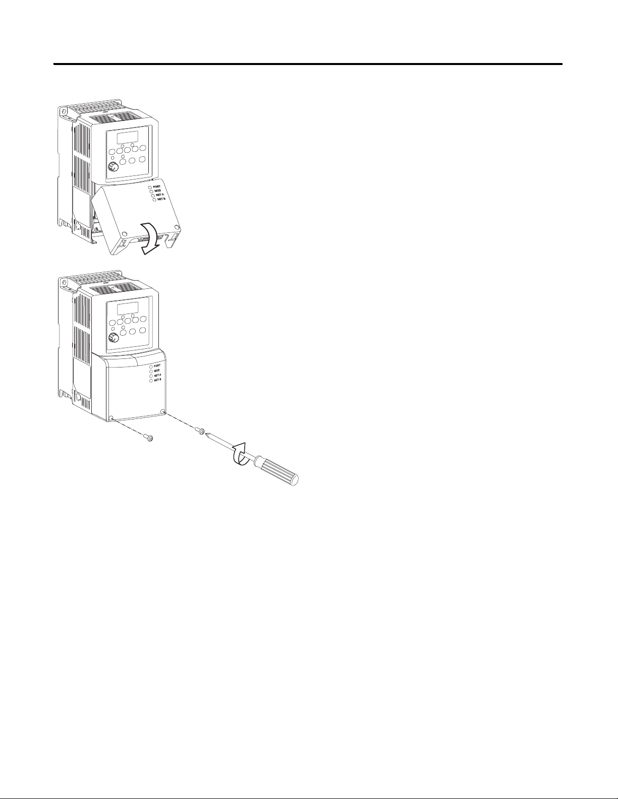
Add a PowerFlex 40 Drive Chapter 5
0.5-0.6 N-m
(4-5 lb.-in.)
3. Place the adapter cover on the PowerFlex drive.
4. Tighten the screws.
5. Connect the network cable to the adapter.
6. Apply power to the PowerFlex 40 drive.
0.5…0.6 Nm
(4…5 lb-in)
Publication IASIMP-QS010B-EN-P - October 2009 87
Page 88
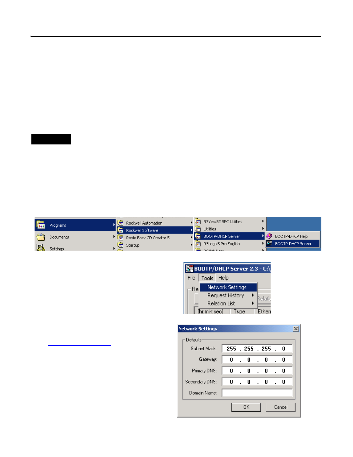
Chapter 5 Add a PowerFlex 40 Drive
TIP
Devices on the EtherNet/IP network broadcast requests for IP addresses until the IP addresses have been
assigned.
The procedure in this chapter uses the BOOTP server packaged with RSLogix 5000 programming software
to assign IP addresses, however, any industry-standard BootP server can be used.
1. After you have installed and connected your adapter, launch the BOOTP/DHCP
Server utility.
2. From the Tools menu, choose Network
Settings.
3. Enter the Subnet Mask from the
Network Worksheet
.
4. Click OK.
Assign an IP Address to the PowerFlex 40 Drive
EtherNet/IP network
In this chapter, you use the BOOTP/DHCP server to assign an IP address to the PowerFlex
40 drive. You use the BootP server that was installed with RSLogix 5000 programming
software.
88 Publication IASIMP-QS010B-EN-P - October 2009
Page 89

The Request History displays
all the devices, including the
drive, on your network that
need an IP address. The
Ethernet address (MAC ID) of
the drive corresponds with the
address you recorded on
Network Worksheet.
5. Double-click the request
from your adapter.
6. Enter the IP address and
record it on the
Network Worksheet
inside the back cover.
If you are not using an isolated
network, obtain these numbers
from your network
administrator.
7. Click OK.
8. To disable BootP/DHCP, select the drive from the Relation List and click Disable
BOOTP/DHCP.
[Disable BOOTP/DHCP] Command successful
appears in the Status bar.
9. Close the BOOTP/DHCP Server utility.
If you are prompted to save changes, click No.
IMPORTANT
For a device to retain its IP address through a power cycle, BootP/DHCP must be disabled. Complete step
8 to disable BootP/DHCP for the drive.
IP Addresses Assigned Successfully
Add a PowerFlex 40 Drive Chapter 5
Publication IASIMP-QS010B-EN-P - October 2009 89
Page 90

Chapter 5 Add a PowerFlex 40 Drive
1. Verify that you are not online with the
packaged controller.
2. Right-click your network port and choose
New Module.
3. Expand Drives.
4. Select the PowerFlex 40-E.
5. Click OK.
6. In the Name box, type
a name for the drive.
7. Enter the IP Address
for your drive.
Use the
Network Worksheet
as a reference.
8. Click Change.
Add the Drive to the Project
90 Publication IASIMP-QS010B-EN-P - October 2009
Page 91

9. From the Electronic Keying
pull-down menu, select
Disable Keying.
10. Click OK.
11. Click OK again.
The PowerFlex 40 drive is
added to the controller
organizer.
Add a PowerFlex 40 Drive Chapter 5
Publication IASIMP-QS010B-EN-P - October 2009 91
Page 92

Chapter 5 Add a PowerFlex 40 Drive
TIP
2. Click the Controller
Status icon and choose
Download.
3. Click Download.
The project downloads to the
controller.
1. If you have not already done so, move
the keyswitch on your controller to
PROG.
Download the Project
If you receive a fault message on your PowerFlex 40 drive, press on the
keypad to clear the fault.
92 Publication IASIMP-QS010B-EN-P - October 2009
Page 93

Edit PowerFlex 40 Parameter Values
TIP
Step Displayed
1. Press .
The parameter number is displayed and blinks.
2. Press to select the group letter.
The group letter blinks.
3. Press or to scroll through the group letters.
4. Press to select the desired group letter.
The parameter number blinks.
5. Press or to scroll through the parameter numbers.
6. Press to select the desired parameter number.
The parameter value is displayed.
7. Press or to scroll through the parameter values.
The values blink as you scroll through them.
8. Press to select the desired parameter value.
The parameter stops blinking.
9. Press to return to the parameter number.
10.Follow this procedure to change other parameter values, or
press repeatedly to return to the value display.
VOLTS
AMPS
HERTZ
FAULTPROGRAM
VOLTS
AMPS
HERTZ
FAULTPROGRAM
VOLTS
AMPS
HERTZ
FAULTPROGRAM
VOLTS
AMPS
HERTZ
FAULTPROGRAM
VOLTS
AMPS
HERTZ
FAULTPROGRAM
Use the table below as a reference when editing parameter values as instructed on
Add a PowerFlex 40 Drive Chapter 5
page 94
.
When power is first applied to the PowerFlex 40 drive, the display defaults to the
current value.
Reference for Editing Parameters
VOLTS
AMPS
HERTZ
FAULTPROGRAM
VOLTS
AMPS
HERTZ
FAULTPROGRAM
VOLTS
AMPS
HERTZ
FAULTPROGRAM
Publication IASIMP-QS010B-EN-P - October 2009 93
Page 94

Chapter 5 Add a PowerFlex 40 Drive
Use the reference on page 93 to make the following parameter value edits on your PowerFlex
40 drive.
1. If your PowerFlex 40 drive has been previously used, reset it to factory defaults.
a. Change the value of parameter P041 from 0 to 1.
The drive is reset and fault F048 is displayed and blinks.
b. Press to clear the fault.
c. Press to return to editing parameters.
2. Change the value of parameters P036 and P038 from 0 to 5.
Changing these parameters switches control the Start Source and the Speed Reference
from the keypad to the communication port. This enables you to control these functions
by using RSLogix 5000 tags.
3. Press to accept parameter edits.
4. Press to return to the speed display.
94 Publication IASIMP-QS010B-EN-P - October 2009
Page 95

Test the PowerFlex 40 Tags
2. Double-click Controller Tags.
3. Expand the PowerFlex 40
output tag.
4. At the O.FreqCommand
Tag, enter 555.
The value 555 equals 55.5 Hz.
1. Move the controller keyswitch
to RUN.
TIP
To change a tag in RSLogix 5000 software:
1. Select the tag value.
2. Enter or select the desired value.
3. Press <Enter>.
Add a PowerFlex 40 Drive Chapter 5
Publication IASIMP-QS010B-EN-P - October 2009 95
Page 96
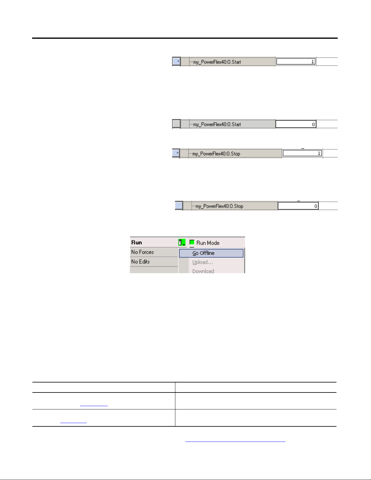
Chapter 5 Add a PowerFlex 40 Drive
4. At the O.Start tag, enter 1.
The drive begins to run and the display
registers the drive’s speed until it reaches 55.5
Hz.
5. After the drive has reached 55.5 Hz,
enter 0 at the O.Start tag.
6. At the O.Stop tag, enter 1.
The drive begins to slow until reaching 0.0 Hz.
7. When the drive reaches 0.0 Hz, enter
0 at the O.Stop tag.
8. Go Offline.
By starting and stopping the drive, you verified that:
• the controller is correctly communicating with the drive.
• the drive can receive simple commands.
Additional Resources
Resource Topic
Logix5000 Controllers Common Procedures Programming
Manual, publication 1756-PM001
PowerFlex 40 Adjustable Frequency AC Drive User Manual,
publication 22B-UM001
Provides details about adding and configuring modules, establishing
communication, and writing ladder logic.
Provides information about installing, programming, editing
parameters, and troubleshooting the PowerFlex 70 drive.
Publications are available for viewing or electronic download at http://literature.rockwellautomation.com.
96 Publication IASIMP-QS010B-EN-P - October 2009
Page 97

Chapter
6
Add a PanelView Plus 600 Terminal
In this chapter, you mount and wire power to a PanelView Plus terminal, configure network
communication, and make network connections. You also use RSView software to create
indicators to represent the push button and output you created in Chapter 3
application to the PanelView Plus terminal so you can test communication with the
controller.
Before You Begin
• Create a project in RSLogix 5000 programming software, see Chapter 3.
. You transfer the
• Install and configure your network, see Chapter 1
and 2.
What You Need
• FactoryTalk View Studio Machine Edition software.
• PanelView Plus terminal - this quick start uses a PanelView Plus 600 terminal.
• One power supply, if you are using a PanelView Plus powered by DC power. We
recommend either a 1794-PS3 or a 2711P-RSACDIN, but any DC power supply can be
used.
• Ethernet cable and switch.
• For a serial connection, 2706-NC13 cable.
97Publication IASIMP-QS010B-EN-P - October 2009 97
Page 98
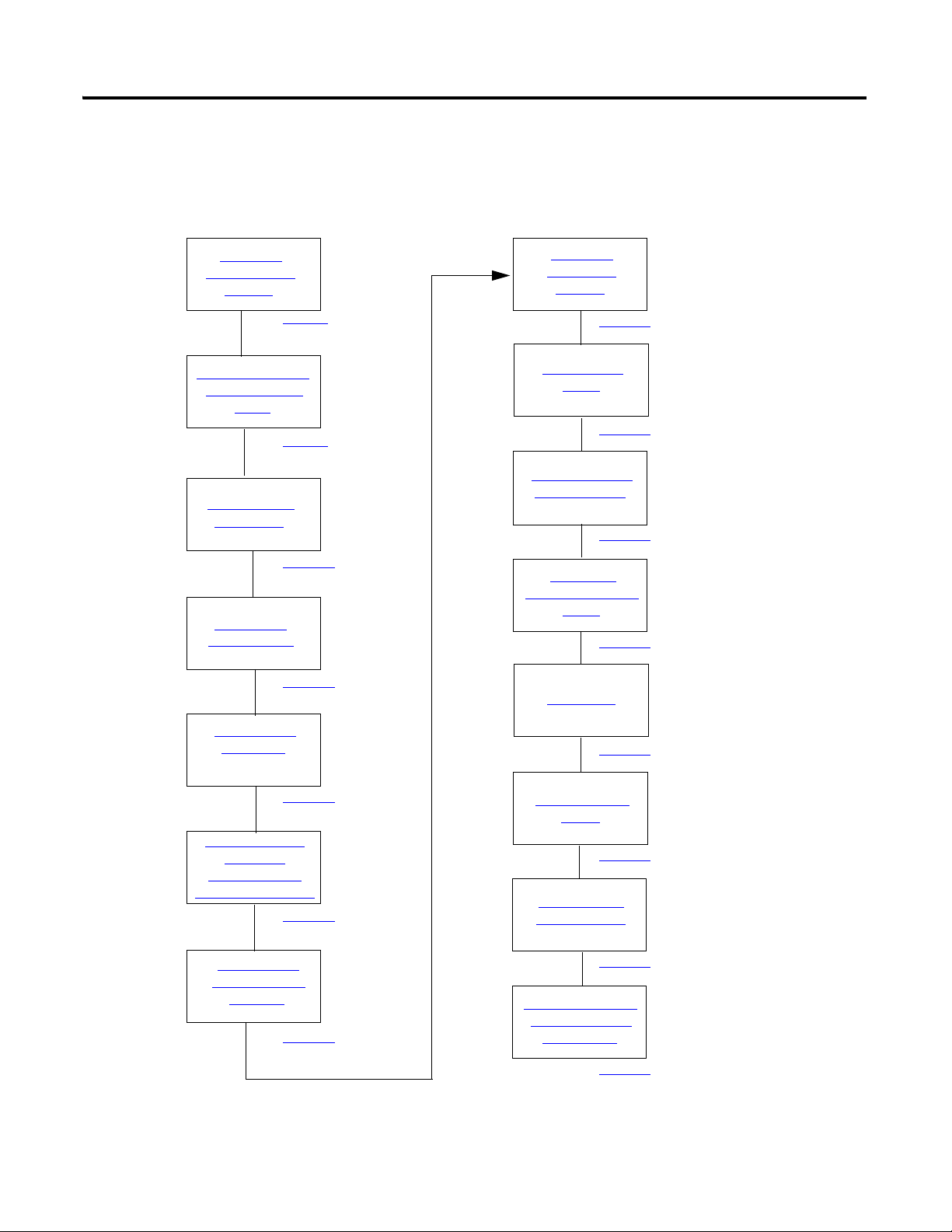
Chapter 6 Add a PanelView Plus 600 Terminal
Create a New
Application
Create an RSLinx
Enterprise
Configuration in
FactoryTalk View ME
Create Device
Shortcuts to the
Controller
Create the
OB16_Light
Indicator
Create a Push
Button
Test the Indicator
and Push Button
page 102
page 103
page 105
page 110
page 113
page 115
Add a Goto
Configuration Mode
Button
page 117
Assign Keys
page 118
Assign an Initial
Screen
page 120
Transfer to the
PanelView Plus
page 121
Test the Application
on the PanelView
Plus Terminal
page 123
Mount the
PanelView Plus
Terminal
page 99
Wire the PanelView
Plus Terminal for
Power
page 99
Make Network
Connections
page 100
Assign an IP
Address to the
page 101
Follow These Steps
If you have a PanelView Plus terminal, complete these steps.
98 Publication IASIMP-QS010B-EN-P - October 2009
Page 99
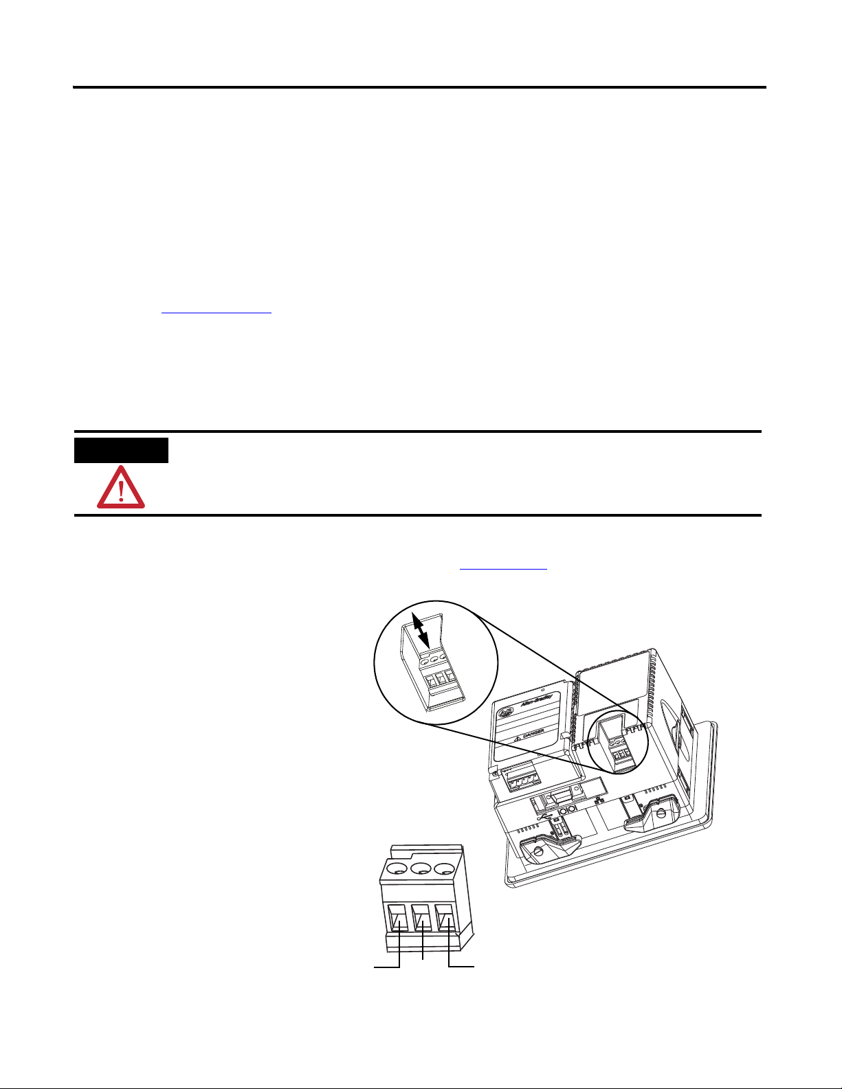
Add a PanelView Plus 600 Terminal Chapter 6
For additional information about wiring power for the PanelView Plus 600 terminal, see the PanelView Plus
400 and 600 Terminals Installation Instructions, publication 2711P-IN002.
WARNING
Verify that all incoming power is turned off before wiring power.
1. Remove the wiring terminal
block using a flat-blade
screwdriver to gently pry the
terminal block from the slot.
2. Connect power wires as shown
in the diagram.
3. Insert the wiring terminal
block and press it into place.
AC Power Wiring
L1
L2/N
Protective Earth Ground
Mount the PanelView Plus Terminal
2711P-K10C4D1 terminal and all packaged controllers
For the purpose of this quick start, the PanelView Plus terminal can be propped on a desktop.
For further mounting instructions, see the PanelView Plus Terminals User Manual,
publication 2711P-UM001
.
Wire the PanelView Plus Terminal for Power
Publication IASIMP-QS010B-EN-P - October 2009 99
Page 100

Chapter 6 Add a PanelView Plus 600 Terminal
Ethernet cable connection.
Serial cable connection (from
1769-L23-QBFC1B serial port).
Make Network Connections
Required for all controllers
100 Publication IASIMP-QS010B-EN-P - October 2009
 Loading...