

Page 1

Integrated Motion on the EtherNet/IP Network: Configuration and Startup
ControlLogix, CompactLogix, GuardLogix,
Compact GuardLogix, iTRAK 5730, Kinetix 350, Kinetix 5300,
Kinetix 5500, Kinetix 5700, Kinetix 6500, PowerFlex 527,
PowerFlex 755
User Manual
Original Instructions
Page 2
Integrated Motion on the EtherNet/IP Network: Configuration and Startup User Manual
Important User Information
Read this document and the documents listed in the additional resources section about installation, configuration, and
operation of this equipment before you install, configure, operate, or maintain this product. Users are required to familiarize
themselves with installation and wiring instructions in addition to requirements of all applicable codes, laws, and standards.
Activities including installation, adjustments, putting into service, use, assembly, disassembly, and maintenance are required to
be carried out by suitably trained personnel in accordance with applicable code of practice.
If this equipment is used in a manner not specified by the manufacturer, the protection provided by the equipment may be
impaired.
In no event will Rockwell Automation, Inc. be responsible or liable for indirect or consequential damages resulting from the use
or application of this equipment.
The examples and diagrams in this manual are included solely for illustrative purposes. Because of the many variables and
requirements associated with any particular installation, Rockwell Automation, Inc. cannot assume responsibility or liability for
actual use based on the examples and diagrams.
No patent liability is assumed by Rockwell Automation, Inc. with respect to use of information, circuits, equipment, or software
described in this manual.
Reproduction of the contents of this manual, in whole or in part, without written permission of Rockwell Automation, Inc., is
prohibited.
Throughout this manual, when necessary, we use notes to make you aware of safety considerations.
WARNING: Identifies information about practices or circumstances that can cause an explosion in a hazardous environment, which
may lead to personal injury or death, property damage, or economic loss.
ATTENTION: Identifies information about practices or circumstances that can lead to personal injury or death, property damage,
or economic loss. Attentions help you identify a hazard, avoid a hazard, and recognize the consequence.
IMPORTANT Identifies information that is critical for successful application and understanding of the product.
Labels may also be on or inside the equipment to provide specific precautions.
SHOCK HAZARD: Labels may be on or inside the equipment, for example, a drive or motor, to alert people that dangerous voltage
may be present.
BURN HAZARD: Labels may be on or inside the equipment, for example, a drive or motor, to alert people that surfaces may reach
dangerous temperatures.
ARC FLASH HAZARD: Labels may be on or inside the equipment, for example, a motor control center, to alert people to potential Arc
Flash. Arc Flash will cause severe injury or death. Wear proper Personal Protective Equipment (PPE). Follow ALL Regulatory
requirements for safe work practices and for Personal Protective Equipment (PPE).
2 Rockwell Automation Publication MOTION-UM003L-EN-P - November 2020
Page 3

Table of Contents
Preface . . . . . . . . . . . . . . . . . . . . . . . . . . . . . . . . . . . . . . . . . . . . . . . . . . . . . . . 9
About This Publication . . . . . . . . . . . . . . . . . . . . . . . . . . . . . . . . . . . . . . . . . . . 9
Download Firmware, AOP, EDS, and Other Files . . . . . . . . . . . . . . . . . . . . 9
Summary of Changes. . . . . . . . . . . . . . . . . . . . . . . . . . . . . . . . . . . . . . . . . . . . . 9
Additional Resources . . . . . . . . . . . . . . . . . . . . . . . . . . . . . . . . . . . . . . . . . . . . . 9
Chapter 1
Components of a Motion System Controller, Communication, Drive, and Software Options . . . . . . . . . . 11
Help for Selecting Drives and Motors . . . . . . . . . . . . . . . . . . . . . . . . . . . . . 14
Chapter 2
Configure Drive Properties Before You Begin . . . . . . . . . . . . . . . . . . . . . . . . . . . . . . . . . . . . . . . . . . . . . . . 16
Add a Kinetix Drive . . . . . . . . . . . . . . . . . . . . . . . . . . . . . . . . . . . . . . . . . . . . . 18
Add a PowerFlex Drive. . . . . . . . . . . . . . . . . . . . . . . . . . . . . . . . . . . . . . . . . . . 19
Add a Peripheral Device for PowerFlex 755 Drives . . . . . . . . . . . . . . . 20
Add an iTRAK Section, Mover, or Power Supply . . . . . . . . . . . . . . . . . . . . 21
Configure Module Definition . . . . . . . . . . . . . . . . . . . . . . . . . . . . . . . . . . . . 23
Safety Application Types . . . . . . . . . . . . . . . . . . . . . . . . . . . . . . . . . . . . . 24
Connection Types . . . . . . . . . . . . . . . . . . . . . . . . . . . . . . . . . . . . . . . . . . . 25
Safety Instance . . . . . . . . . . . . . . . . . . . . . . . . . . . . . . . . . . . . . . . . . . . . . . 25
Motion Safety Type . . . . . . . . . . . . . . . . . . . . . . . . . . . . . . . . . . . . . . . . . . 26
Configure Power Settings. . . . . . . . . . . . . . . . . . . . . . . . . . . . . . . . . . . . . . . . 26
Configure Digital Inputs. . . . . . . . . . . . . . . . . . . . . . . . . . . . . . . . . . . . . . . . . 29
Configure Digital Outputs . . . . . . . . . . . . . . . . . . . . . . . . . . . . . . . . . . . . . . . 31
Configure Safety Settings. . . . . . . . . . . . . . . . . . . . . . . . . . . . . . . . . . . . . . . . 31
Configure Safety Connections . . . . . . . . . . . . . . . . . . . . . . . . . . . . . . . . 32
Generate the Safety Network Number
(Integrated safety drives only) . . . . . . . . . . . . . . . . . . . . . . . . . . . . . . . . 33
Configure Track Sections . . . . . . . . . . . . . . . . . . . . . . . . . . . . . . . . . . . . . . . . 35
Rockwell Automation Publication MOTION-UM003L-EN-P - November 2020 3
Page 4

Table of Contents
Chapter 3
Configure Axis Properties Create an Associated Axis . . . . . . . . . . . . . . . . . . . . . . . . . . . . . . . . . . . . . . . . 37
Create an Axis . . . . . . . . . . . . . . . . . . . . . . . . . . . . . . . . . . . . . . . . . . . . . . . 37
Specify Feedback Assignments. . . . . . . . . . . . . . . . . . . . . . . . . . . . . . . . 39
Create a Motion Group . . . . . . . . . . . . . . . . . . . . . . . . . . . . . . . . . . . . . . . . . . 40
Set the Base Update Period . . . . . . . . . . . . . . . . . . . . . . . . . . . . . . . . . . . 41
Associate Axes to the Motion Group. . . . . . . . . . . . . . . . . . . . . . . . . . . . . . . 43
Configure an Axis and Control Mode . . . . . . . . . . . . . . . . . . . . . . . . . . . . . 43
Specify the Motor Data Source . . . . . . . . . . . . . . . . . . . . . . . . . . . . . . . . . . . 49
Choose the Catalog Number as the Motor Data Source . . . . . . . . . . 50
Choose Nameplate as the Motor Data Source. . . . . . . . . . . . . . . . . . . 51
Choose Motor NV or Drive NV as the Motor Data Source . . . . . . . . 53
Display Motor Model Information . . . . . . . . . . . . . . . . . . . . . . . . . . . . . . . . 53
Use Motor Analyzer . . . . . . . . . . . . . . . . . . . . . . . . . . . . . . . . . . . . . . . . . . . . . 54
Assign Motor Feedback . . . . . . . . . . . . . . . . . . . . . . . . . . . . . . . . . . . . . . . . . . 55
Configure Load Feedback . . . . . . . . . . . . . . . . . . . . . . . . . . . . . . . . . . . . . . . . 59
Configure Master Feedback . . . . . . . . . . . . . . . . . . . . . . . . . . . . . . . . . . . . . . 60
Configure Feedback Only Axis Properties . . . . . . . . . . . . . . . . . . . . . . 60
Configure Actions. . . . . . . . . . . . . . . . . . . . . . . . . . . . . . . . . . . . . . . . . . . . . . . 60
Configure Exceptions . . . . . . . . . . . . . . . . . . . . . . . . . . . . . . . . . . . . . . . . . . . 62
Chapter 4
Axis Scheduling Timing Model . . . . . . . . . . . . . . . . . . . . . . . . . . . . . . . . . . . . . . . . . . . . . . . . . . 65
One Cycle Timing. . . . . . . . . . . . . . . . . . . . . . . . . . . . . . . . . . . . . . . . . . . . 66
Axis Scheduling Configuration . . . . . . . . . . . . . . . . . . . . . . . . . . . . . . . . . . . 68
Configure the Update Periods . . . . . . . . . . . . . . . . . . . . . . . . . . . . . . . . . . . . 69
Motion Utilization . . . . . . . . . . . . . . . . . . . . . . . . . . . . . . . . . . . . . . . . . . . . . . 76
Chapter 5
Configuration Examples for a
Kinetix Drive
Example 1: Position Loop with Motor Feedback Only . . . . . . . . . . . . . . . 77
Example 2: Position Loop with Dual Feedback . . . . . . . . . . . . . . . . . . . . . 80
Example 3: Feedback Only . . . . . . . . . . . . . . . . . . . . . . . . . . . . . . . . . . . . . . . 85
Example 4: Kinetix 5500 Drive, Velocity Loop with
Motor Feedback. . . . . . . . . . . . . . . . . . . . . . . . . . . . . . . . . . . . . . . . . . . . . . . . . 89
Example 5: Kinetix 350 Drive, Position Loop with
Motor Feedback. . . . . . . . . . . . . . . . . . . . . . . . . . . . . . . . . . . . . . . . . . . . . . . . . 93
Example 6: Kinetix 5700 Drive, Frequency Control with
No Feedback. . . . . . . . . . . . . . . . . . . . . . . . . . . . . . . . . . . . . . . . . . . . . . . . . . . . 97
Example 7: 842E-CM Integrated Motion Encoder with
Master Feedback . . . . . . . . . . . . . . . . . . . . . . . . . . . . . . . . . . . . . . . . . . . . . . . 100
4 Rockwell Automation Publication MOTION-UM003L-EN-P - November 2020
Page 5

Chapter 6
Tab le o f Conte nts
Axis Configuration Examples for
the PowerFlex 755 Drive
Example 1: Position Loop with Motor Feedback Via a
UFB Feedback Device. . . . . . . . . . . . . . . . . . . . . . . . . . . . . . . . . . . . . . . . . . . 104
Example 2: Position Loop with Dual Motor Feedback Via a
UFB Feedback Device. . . . . . . . . . . . . . . . . . . . . . . . . . . . . . . . . . . . . . . . . . . 107
Example 3: Velocity Loop with Motor Feedback Via a
UFB Feedback Device. . . . . . . . . . . . . . . . . . . . . . . . . . . . . . . . . . . . . . . . . . . . 111
Example 4: Velocity Loop with No Feedback . . . . . . . . . . . . . . . . . . . . . . 114
Example 5: Frequency Control with No Feedback. . . . . . . . . . . . . . . . . . 116
Example 6: Torque Loop with Feedback . . . . . . . . . . . . . . . . . . . . . . . . . . 121
Chapter 7
Axis Configuration Examples for
the PowerFlex 527 Drive
Example 1: Frequency Control with No Feedback. . . . . . . . . . . . . . . . . . 125
Example 2: Velocity Control with Motor Feedback. . . . . . . . . . . . . . . . . 130
Example 3: Position Control with Motor Feedback. . . . . . . . . . . . . . . . . 133
Chapter 8
Commission an Axis Scaling. . . . . . . . . . . . . . . . . . . . . . . . . . . . . . . . . . . . . . . . . . . . . . . . . . . . . . . . 137
Direct Coupled Rotary . . . . . . . . . . . . . . . . . . . . . . . . . . . . . . . . . . . . . . 139
Direct Coupled Linear. . . . . . . . . . . . . . . . . . . . . . . . . . . . . . . . . . . . . . . 140
Rotary Transmission. . . . . . . . . . . . . . . . . . . . . . . . . . . . . . . . . . . . . . . . 140
Linear Actuator. . . . . . . . . . . . . . . . . . . . . . . . . . . . . . . . . . . . . . . . . . . . . 141
Changing Scaling Factors . . . . . . . . . . . . . . . . . . . . . . . . . . . . . . . . . . . 141
Hookup Tests. . . . . . . . . . . . . . . . . . . . . . . . . . . . . . . . . . . . . . . . . . . . . . . . . . 142
Run a Motor and Feedback Test . . . . . . . . . . . . . . . . . . . . . . . . . . . . . . 144
Run a Motor Feedback Test . . . . . . . . . . . . . . . . . . . . . . . . . . . . . . . . . . 146
Run a Marker Test . . . . . . . . . . . . . . . . . . . . . . . . . . . . . . . . . . . . . . . . . . 146
Applying the Commutation Hookup Test. . . . . . . . . . . . . . . . . . . . . . . . . 147
Unknown Commutation Offset . . . . . . . . . . . . . . . . . . . . . . . . . . . . . . 148
Verification of Known Commutation Offset. . . . . . . . . . . . . . . . . . . 148
Non-standard or Incorrect Wiring . . . . . . . . . . . . . . . . . . . . . . . . . . . 148
Run a Commutation Test . . . . . . . . . . . . . . . . . . . . . . . . . . . . . . . . . . . . . . . 149
Polarity . . . . . . . . . . . . . . . . . . . . . . . . . . . . . . . . . . . . . . . . . . . . . . . . . . . . . . . 150
Autotune . . . . . . . . . . . . . . . . . . . . . . . . . . . . . . . . . . . . . . . . . . . . . . . . . . . . . . 150
Load . . . . . . . . . . . . . . . . . . . . . . . . . . . . . . . . . . . . . . . . . . . . . . . . . . . . . . . . . . 154
Load Observer . . . . . . . . . . . . . . . . . . . . . . . . . . . . . . . . . . . . . . . . . . . . . . . . . 156
Benefits of Load Observer . . . . . . . . . . . . . . . . . . . . . . . . . . . . . . . . . . . 156
How Load Observer Functions . . . . . . . . . . . . . . . . . . . . . . . . . . . . . . . 157
Load Observer Configuration . . . . . . . . . . . . . . . . . . . . . . . . . . . . . . . . 158
Adaptive Tuning. . . . . . . . . . . . . . . . . . . . . . . . . . . . . . . . . . . . . . . . . . . . 159
Benefits of Adaptive Tuning . . . . . . . . . . . . . . . . . . . . . . . . . . . . . . . . . 159
How Adaptive Tuning Functions . . . . . . . . . . . . . . . . . . . . . . . . . . . . . 159
Adaptive Tuning Configuration . . . . . . . . . . . . . . . . . . . . . . . . . . . . . . 161
Command Notch Filters. . . . . . . . . . . . . . . . . . . . . . . . . . . . . . . . . . . . . 165
Load Ratio Data from Motion Analyzer. . . . . . . . . . . . . . . . . . . . . . . . . . . 166
Test an Axis with Motion Direct Commands . . . . . . . . . . . . . . . . . . . . . . 166
Access Motion Direct Commands for an Axis or Group . . . . . . . . . 167
Rockwell Automation Publication MOTION-UM003L-EN-P - November 2020 5
Page 6

Table of Contents
Understanding STO Bypass When Using
Motion Direct Commands. . . . . . . . . . . . . . . . . . . . . . . . . . . . . . . . . . . 169
Chapter 9
Homing Guidelines for Homing . . . . . . . . . . . . . . . . . . . . . . . . . . . . . . . . . . . . . . . . . 174
Active Homing . . . . . . . . . . . . . . . . . . . . . . . . . . . . . . . . . . . . . . . . . . . . . 175
Passive Homing . . . . . . . . . . . . . . . . . . . . . . . . . . . . . . . . . . . . . . . . . . . . 175
Examples. . . . . . . . . . . . . . . . . . . . . . . . . . . . . . . . . . . . . . . . . . . . . . . . . . . . . . 176
Active Homing . . . . . . . . . . . . . . . . . . . . . . . . . . . . . . . . . . . . . . . . . . . . . 176
Passive Homing . . . . . . . . . . . . . . . . . . . . . . . . . . . . . . . . . . . . . . . . . . . . 179
Absolute Position Recovery (APR). . . . . . . . . . . . . . . . . . . . . . . . . . . . . . . . 179
APR Terminology . . . . . . . . . . . . . . . . . . . . . . . . . . . . . . . . . . . . . . . . . . . 180
Position Recovery Considerations for Logix5000 Controllers . . . 180
Absolute Feedback Device . . . . . . . . . . . . . . . . . . . . . . . . . . . . . . . . . . . 181
SERCOS Versus Integrated Motion on Ethernet Networks . . . . . 181
APR Scenarios. . . . . . . . . . . . . . . . . . . . . . . . . . . . . . . . . . . . . . . . . . . . . . 181
APR Faults . . . . . . . . . . . . . . . . . . . . . . . . . . . . . . . . . . . . . . . . . . . . . . . . . . . . 185
APR Fault Conditions . . . . . . . . . . . . . . . . . . . . . . . . . . . . . . . . . . . . . . . 185
APR Fault Generation . . . . . . . . . . . . . . . . . . . . . . . . . . . . . . . . . . . . . . . 186
APR Fault Examples . . . . . . . . . . . . . . . . . . . . . . . . . . . . . . . . . . . . . . . . 188
Resetting an APR Fault . . . . . . . . . . . . . . . . . . . . . . . . . . . . . . . . . . . . . . 190
Absolute Position Loss without APR Faults . . . . . . . . . . . . . . . . . . . . 190
Behavior of APR for Incremental Encoders. . . . . . . . . . . . . . . . . . . . 190
Chapter 10
Manual Tune When to Manually Tune an Axis . . . . . . . . . . . . . . . . . . . . . . . . . . . . . . . . . 191
Axis Configuration Types. . . . . . . . . . . . . . . . . . . . . . . . . . . . . . . . . . . . 191
Current Tuning Configuration. . . . . . . . . . . . . . . . . . . . . . . . . . . . . . . 192
Loop Responses . . . . . . . . . . . . . . . . . . . . . . . . . . . . . . . . . . . . . . . . . . . . 192
Tune The Axis . . . . . . . . . . . . . . . . . . . . . . . . . . . . . . . . . . . . . . . . . . . . . . . . . 194
Motion Generator and Motion Direct Commands . . . . . . . . . . . . . . . . . 195
Additional Tune. . . . . . . . . . . . . . . . . . . . . . . . . . . . . . . . . . . . . . . . . . . . . . . . 197
Feedforward Parameters . . . . . . . . . . . . . . . . . . . . . . . . . . . . . . . . . . . . 197
Compensation Parameters . . . . . . . . . . . . . . . . . . . . . . . . . . . . . . . . . . 198
Torque Notch Filters Parameters . . . . . . . . . . . . . . . . . . . . . . . . . . . . . 198
Torque Filters Parameters . . . . . . . . . . . . . . . . . . . . . . . . . . . . . . . . . . . 199
Command Notch Filters Parameters. . . . . . . . . . . . . . . . . . . . . . . . . . 199
Adaptive Tuning Parameters. . . . . . . . . . . . . . . . . . . . . . . . . . . . . . . . 200
Limits Parameters . . . . . . . . . . . . . . . . . . . . . . . . . . . . . . . . . . . . . . . . . . 201
Planner Parameters. . . . . . . . . . . . . . . . . . . . . . . . . . . . . . . . . . . . . . . . . 202
Configure Torque Values . . . . . . . . . . . . . . . . . . . . . . . . . . . . . . . . . . . . 202
Monitor Tags with the Quick Watch Window . . . . . . . . . . . . . . . . . . . . . 203
Use Motion Generator . . . . . . . . . . . . . . . . . . . . . . . . . . . . . . . . . . . . . . . . . . 204
6 Rockwell Automation Publication MOTION-UM003L-EN-P - November 2020
Page 7

Tab le o f Conte nts
Chapter 11
Status, Faults, and Alarms Faults and Alarms Dialog Box . . . . . . . . . . . . . . . . . . . . . . . . . . . . . . . . . . . 207
QuickView Pane . . . . . . . . . . . . . . . . . . . . . . . . . . . . . . . . . . . . . . . . . . . . . . . 209
Data Monitor . . . . . . . . . . . . . . . . . . . . . . . . . . . . . . . . . . . . . . . . . . . . . . . . . . 209
Motion Status . . . . . . . . . . . . . . . . . . . . . . . . . . . . . . . . . . . . . . . . . . . . . . . . . 210
Drive Status Indicators . . . . . . . . . . . . . . . . . . . . . . . . . . . . . . . . . . . . . . . . . 211
Connection Faults and Errors . . . . . . . . . . . . . . . . . . . . . . . . . . . . . . . . . . . 211
Motion Faults. . . . . . . . . . . . . . . . . . . . . . . . . . . . . . . . . . . . . . . . . . . . . . . . . . 212
Manage Motion Faults. . . . . . . . . . . . . . . . . . . . . . . . . . . . . . . . . . . . . . . . . . 212
Configure the Exception Actions for AXIS_CIP_DRIVE. . . . . . . . . . . . 213
Inhibit an Axis . . . . . . . . . . . . . . . . . . . . . . . . . . . . . . . . . . . . . . . . . . . . . . . . . 215
Example: Inhibit an Axis . . . . . . . . . . . . . . . . . . . . . . . . . . . . . . . . . . . . 217
Example: Uninhibit an Axis. . . . . . . . . . . . . . . . . . . . . . . . . . . . . . . . . . 218
Appendix A
Parameter Group Dialog Boxes Parameter Group Dialog Boxes . . . . . . . . . . . . . . . . . . . . . . . . . . . . . . . . . . 219
Appendix B
Program a Velocity Profile and
Jerk Rate
Program a Velocity Profile and Jerk Rate . . . . . . . . . . . . . . . . . . . . . . . . . 221
Definition of Jerk . . . . . . . . . . . . . . . . . . . . . . . . . . . . . . . . . . . . . . . . . . . 221
Choose a Profile . . . . . . . . . . . . . . . . . . . . . . . . . . . . . . . . . . . . . . . . . . . . 222
Use % of Time for the Easiest Programming of Jerk . . . . . . . . . . . . 222
Velocity Profile Effects . . . . . . . . . . . . . . . . . . . . . . . . . . . . . . . . . . . . . . 223
Jerk Rate Calculation. . . . . . . . . . . . . . . . . . . . . . . . . . . . . . . . . . . . . . . . 224
Profile Operand . . . . . . . . . . . . . . . . . . . . . . . . . . . . . . . . . . . . . . . . . . . . 228
Enter Basic Logic . . . . . . . . . . . . . . . . . . . . . . . . . . . . . . . . . . . . . . . . . . . . . . 232
Example Motion Control Program . . . . . . . . . . . . . . . . . . . . . . . . . . . 232
Download a Project . . . . . . . . . . . . . . . . . . . . . . . . . . . . . . . . . . . . . . . . . 233
Choose a Motion Instruction. . . . . . . . . . . . . . . . . . . . . . . . . . . . . . . . . . . . 234
Troubleshoot Axis Motion. . . . . . . . . . . . . . . . . . . . . . . . . . . . . . . . . . . . . . . 235
Why Does My Axis Accelerate When I Stop It? . . . . . . . . . . . . . . . . . 236
Why Does My Axis Overshoot Its Target Speed? . . . . . . . . . . . . . . . 237
Why Is There a Delay When I Stop and Then Restart a Jog? . . . . . 240
Why Does The Axis Reverse Direction When Stopped
and Started? . . . . . . . . . . . . . . . . . . . . . . . . . . . . . . . . . . . . . . . . . . . . . . . 242
Programming with the MDSC Function . . . . . . . . . . . . . . . . . . . . . . . . . . 243
Rockwell Automation Publication MOTION-UM003L-EN-P - November 2020 7
Page 8

Table of Contents
Appendix C
PowerFlex Out-of-Box
Configuration
Recommended Out-of-Box Settings . . . . . . . . . . . . . . . . . . . . . . . . . . . . . 247
Setting the ACO/AVO Attributefor PowerFlex 527 Drives Only . . . . . . 251
Glossary . . . . . . . . . . . . . . . . . . . . . . . . . . . . . . . . . . . . . . . . . . . . . . . . . . . . . 253
Index . . . . . . . . . . . . . . . . . . . . . . . . . . . . . . . . . . . . . . . . . . . . . . . . . . . . . . . 257
8 Rockwell Automation Publication MOTION-UM003L-EN-P - November 2020
Page 9

Preface
About This Publication
Use this manual to configure an integrated motion on the EtherNet/IP™
network application and to start up your motion solution with a Logix
controller-based system.
This manual is designed to give you a straightforward approach to an
integrated motion control solution. If you have any comments or suggestions,
on the back cover of this manual.
Download Firmware, AOP, EDS, and Other Files
see Documentation Feedback
Download firmware, associated files (such as AOP, EDS, and DTM), and access
product release notes from the Product Compatibility and Download Center at
rok.auto/pcdc
.
Summary of Changes This publication contains the following new or updated information. This list
includes substantive updates only and is not intended to reflect all changes.
Topic Page
Added Information on Kinetix® 5300 servo drives and the iTRAK® 5730 Intelligent Track System Throughout
Restructured Configuration Information into Chapter 1
Updated Drive Function Descriptions 29
Types of Hookup Tests 143
Adaptive Tuning Configuration 161
Revised Descriptions of Command Notch Filters 165
Revised Information on APR Recovery Scenarios 181
Updated Guidance on When to Manually Tune an Axis 191
…Chapter 3 11…37
Additional Resources These documents contain additional information concerning related products
from Rockwell Automation.
Resource Description
842E-CM Integrated Motion Encoder on EtherNet/IP User Manual,
publication 842E-UM002
ControlLogix 5580 and GuardLogix 5580 Controllers User Manual,
publication 1756-UM543
CompactLogix 5380 and Compact GuardLogix 5380 Controllers User Manual,
publication 5069-UM001
ControlLogix System User Manual, publication 1756-UM001
EtherNet/IP Network Devices User Manual, publication ENET-UM006
GuardLogix 5570 Controllers User Manual, publication 1756-UM022
GuardLogix 5570 and Compact GuardLogix 5370 Controller Systems Safety
Reference Manual, publication 1756-RM099
GuardLogix 5580 and Compact GuardLogix 5380 Controller Systems Safety
Reference Manual, publication 1756-RM012
Integrated Motion on the EtherNet/IP Network Reference Manual,
publication MOTION-RM003
Kinetix 350 Single-axis EtherNet/IP Servo Drive User Manual, publication 2097-
UM002
Rockwell Automation Publication MOTION-UM003L-EN-P - November 2020 9
Describes the necessary tasks to install, wire, and troubleshoot your encoder.
Provides information on how to install, configure, program, and operate
ControlLogix® 5580 and GuardLogix® 5580 controllers.
Provides information on how to install, configure, program, and operate
CompactLogix™ 5380 and Compact GuardLogix 5380 controllers.
Describes the necessary tasks to install, configure, program, and operate a ControlLogix system.
Describes how to use EtherNet/IP™ communication modules in Logix 5000™ control systems.
Provides information on how to install, configure, and operate GuardLogix 5570 controllers in
Studio 5000 Logix Designer® projects, version 21 or later.
Provides information on how to meet safety application requirements for
GuardLogix 5570 controllers in Studio 5000 Logix Designer projects, version 21 or later.
Describes the necessary tasks to install, configure, program, and operate a ControlLogix system.
Provides a programmer with details about the Integrated Motion on the EtherNet/IP network
Control Modes, Control Methods, and AXIS_CIP_DRIVE Attributes.
Provides detailed information on wiring, power, troubleshooting, and integration with
ControlLogix, or CompactLogix controller platforms.
Page 10
Preface
Resource Description
Kinetix 5300 Single-axis EtherNet/IP Servo Drives User Manual, publication 2198-
UM005
Kinetix 5500 Servo Drives Installation Instructions, publication 2198-IN001
Kinetix 5500 Servo Drives User Manual, publication 2198-UM001
Kinetix 5700 Safe Monitor Functions User Manual, publication 2198-RM001
Kinetix 5700 Servo Drives User Manual, publication 2198-UM002
Kinetix 6200 and Kinetix 6500 Modular Multi-axis Servo Drives User Manual,
publication 2094-UM002
Logix 5000 Controllers Motion Instructions Reference Manual,
publication MOTION-RM002
Logix 5000 Controllers Common Procedures, publication 1756-PM001
Logix 5000 Controllers General Instructions Reference Manual, publication 1756-
RM003
LOGIX 5000 Controllers Advanced Process Control and Drives and Equipment
Phase and Sequence Instructions Reference Manual, publication 1756-RM006
Logix 5000 Controllers Quick Start, publication 1756-QS001 Describes how to get started programming and maintaining Logix5000 controllers.
Motion System Tuning Application Technique, publication MOTION-AT005
PowerFlex 527 Adjustable Frequency AC Drive User Manual, publication 520-
UM002
PowerFlex 750-Series AC Drives Programming Manual, publication 750-PM001
PowerFlex 750-Series AC Drives Reference Manual, publication 750-RM002
PowerFlex 755 Drive Embedded EtherNet/IP Adapter User Manual,
publication 750COM-UM001
PowerFlex 750-Series Safe Speed Monitor Option Module Safety Reference
Manual, publication 750-RM001
PowerFlex 750-Series Safe Torque Off Option Module User Manual,
publication 750-UM002
PowerFlex 755 Integrated Safety - Safe Torque Off Option Module User Manual,
publication 750-UM004
The Integrated Architecture and CIP Sync Configuration Application Technique,
publication IA-AT003
EtherNet/IP Network Devices User Manual, ENET-UM006
Ethernet Reference Manual, ENET-RM002
System Security Design Guidelines Reference Manual, SECURE-RM001
Industrial Components Preventive Maintenance, Enclosures, and Contact Ratings
Specifications, publication IC-TD002
Safety Guidelines for the Application, Installation, and Maintenance of Solid-state
Control, publication SGI-1.1
Industrial Automation Wiring and Grounding Guidelines, publication 1770-4.1 Provides general guidelines for installing a Rockwell Automation industrial system.
Product Certifications website, rok.auto/certifications
. Provides declarations of conformity, certificates, and other certification details.
Provides detailed installation instructions to mount, wire, and troubleshoot the Kinetix® 5300
servo drives, and system integration for your drive and motor/actuator combination with a Logix
5000 controller.
Provides installation instructions for the Kinetix 5500 Integrated Axis Module and Axis Module
components.
Provides information on installation, configuration, start up, troubleshooting, and applications for
the Kinetix 5500 servo drive systems.
Explains how the Kinetix 5700 drives can be used in up to Safety Integrity Level (SIL 3),
Performance Level (PL e) applications.
Provides information on installing, configuring, start up, troubleshooting, and applications for the
Kinetix 5700 servo drive systems.
Provides information on installation, configuration, start up, troubleshooting, and applications for
the Kinetix 6200 and Kinetix 6500 servo drive systems.
Provides a programmer with details about motion instructions for a Logix-based controller.
Provides detailed and comprehensive information about how to program a Logix 5000™
controller.
Provides a programmer with details about general instructions for a Logix-based controller.
Provides a programmer with details about process and drives instructions for a Logix-based
controller.
Provides detailed information on motion system tuning.
Provides information on installation, configuration, start up, troubleshooting, and applications for
the PowerFlex® 527 drive.
Provides information that is necessary to install, start-up, and troubleshoot PowerFlex 750-
Series Adjustable Frequency AC Drives.
Provides detailed drive information including operation, parameter descriptions, and
programming of the AC drive.
Provides information on installation, configuration, start up, troubleshooting, and applications for
the PowerFlex 755 Drive Embedded EtherNet/IP Adapter.
These publications provide detailed information on installation, setup, and operation of the 750Series safety option modules.
Provides detailed configuration information on CIP™ Sync technology and time synchronization.
Describes how to configure and use EtherNet/IP devices to communicate on the EtherNet/IP
network.
Describes basic Ethernet concepts, infrastructure components, and infrastructure features.
Provides guidance on how to conduct security assessments, implement Rockwell Automation
products in a secure system, harden the control system, manage user access, and dispose of
equipment.
Provides a quick reference tool for Allen-Bradley industrial automation controls and assemblies.
Designed to harmonize with NEMA Standards Publication No. ICS 1.1-1987 and provides general
guidelines for the application, installation, and maintenance of solid-state control in the form of
individual devices or packaged assemblies incorporating solid-state components.
You can view or download publications at rok.auto/literature.
10 Rockwell Automation Publication MOTION-UM003L-EN-P - November 2020
Page 11

Components of a Motion System
Topic Page
Controller, Communication, Drive, and Software Options 11
Help for Selecting Drives and Motors 14
Chapter 1
Controller, Communication, Drive, and Software Options
To create an Integrated Motion on EtherNet/IP™ system, you need the
following:
• A Logix 5000™ controller with a connection to the EtherNet/IP network,
either via an embedded Ethernet port or an Ethernet communication
module (See Table 1
•An Integrated Motion drive (see Table 2
•Software
- Studio 5000 Logix Designer® application
-RSLinx® Classic software, version 3.51.00 or later
- For PowerFlex® 755 drives, you need the Add-on Profile, V18 or later.
A safety controller is required for motion and safety applications.
When a PowerFlex 755 drive is used in Integrated Motion on
EtherNet/IP mode, the Logix controller and Studio 5000 Logix
Designer application are the exclusive owners of the drive. A HIM or
other drive software tools, such as DriveExplorer™ and Connected
Components Workbench software, cannot be used to control the
drive or change configuration settings. These tools can only be used
for monitoring.
See the Product Compatibility and Download Center (PCDC)
controller, Ethernet module, and drive firmware revisions, Studio 5000 Logix
Designer required revisions, and compatibility information.
)
)
for minimum
Table 1
depending on the hardware that is used in your application and the
configuration of your axes. For example, you can have eight Position Loop axes
per 1756-EN2T module. Each drive requires one TCP and one CIP™ connection.
If you have other devices that consume TCP connections on the module, it
reduces the number of drives you can support. Only the drives and axes that
are configured for Position Loop are limited. Frequency Control, Velocity
Loop, and Torque Loop configured drives and axes are not limited.
Rockwell Automation Publication MOTION-UM003L-EN-P - November 2020 11
provides information on how many motion axes are supported
Page 12

Chapter 1 Components of a Motion System
Table 1 - Supported Axes by Controller Type
Controller
ControlLogix® 5570,GuardLogix 5570
Armor™ ControlLogix 5570, Armor™ GuardLogix® 5570
Communication Modules
(1)
1756-EN2T, 1756-EN2TF,
1756-EN2TP, 1756-EN2TR
1756-EN3TR 100 Up to 100
Supported Axes
Position Loop Other Loop Types
8Up to 100
1756-EN4TR 100 Up to 100
ControlLogix 5580, GuardLogix 5580
1756-EN2T, 1756-EN2F, 1756-EN2TP,
1756-EN2TR
8Up to 256
1756-EN3TR 256 Up to 256
1756-EN4TR 256 Up to 256
ControlLogix 5580, GuardLogix 5580
1756-L81E, 1756-L81ES
1756-L82E, 1756-L82ES
1756-L83E, 1756-L83ES, 1756-L84E, 1756-L84ES
1756-L85E
Embedded Ethernet
Embedded Ethernet
Embedded Ethernet
Embedded Ethernet
(3)
(3)
(3)
(3)
256 Up to 256
256 Up to 256
256 Up to 256
256 Up to 256
5069-L306ERM, 5069-L306ERMS2 Embedded Ethernet 2 Up to 256
5069-L310ERM, 5069-L310ERMS2 Embedded Ethernet 4 Up to 256
5069-L320ERM, 5069-L320ERMS2 Embedded Ethernet 8 Up to 256
CompactLogix™ 5380, Compact
GuardLogix 5380
5069-L330ERM, 5069-L330ERMS2 Embedded Ethernet 16 Up to 256
5069-L340ERM, 5069-L340ERMS2 Embedded Ethernet 20 Up to 256
5069-L350ERM, 5069-L350ERMS2 Embedded Ethernet 24 Up to 256
5069-L380ERM, 5069-L380ERMS2 Embedded Ethernet 28 Up to 256
5069-L3100ERM, 5069-L3100ERMS2 Embedded Ethernet 32 Up to 256
1769-L18ERM Embedded Ethernet 2 Up to 100
1769-L27ERM Embedded Ethernet 4 Up to 100
1769-L30ERM, 1769-L30ERMS Embedded Ethernet 4 Up to 100
CompactLogix 5370, Compact
GuardLogix 5370, Armor
CompactLogix 5370, Armor Compact
GuardLogix 5370
(1) For more information on Ethernet communication modules, see 1756 ControlLogix Communication Modules Specifications Technical Data, publication 1756-TD003.
(2) Multiple controllers can control drives on a common 1756-ENxTx module, so based on the TCP connection limit, up to 128 can be supported.
(3) ControlLogix 5580 and GuardLogix 5580 can also use Ethernet communication modules to communicate on the EtherNet/IP network.
1769-L33ERM, 1769-L33ERMS
1769-L33ERMO, 1769-L33ERMOS
1769-L36ERM, 1769-L36ERMS
1769-L36ERMO, 1769-L36ERMOS
1769-L37ERM, 1769-L37ERMS, 1769-L37ERMO,
1769-L37ERMOS,
1769-L38ERM, 1769-L38ERMS
1769-L38ERM0, 1769-L38ERM0S
Embedded Ethernet 8 Up to 100
Embedded Ethernet 16 Up to 100
Embedded Ethernet 16 Up to 100
Embedded Ethernet 16 Up to 100
(2)
12 Rockwell Automation Publication MOTION-UM003L-EN-P - November 2020
Page 13

Chapter 1 Components of a Motion System
Table 2 describes the EtherNet/IP drives available for integrated motion.
Table 2 - Integrated Motion EtherNet/IP Drives
Drive Description
842E-CM Absolute
Encoders
Kinetix® 350 The Kinetix 350 drive is a single-axis EtherNet/IP servo drive with hardwired Safe Torque Off (STO) with connection to safety inputs.
Kinetix 5300 The Kinetix 5300 servo drive is an entry-level servo drive integrated on EtherNet/IP.
Kinetix 5500
Kinetix 5700
Kinetix 6500
PowerFlex 527
PowerFlex 755
iTRAK® 5730
Intelligent Track
System
iTRAK Power
Supply
(1) Integrated Motion support of the Integrated Safety Functions option module (20-750-S4) is only available when used with GuardLogix 5580 and Compact GuardLogix 5380 safety controllers.
(2) PowerFlex Drive firmware revision 14 or later required for Integrated Safe Torque Off option module (20-750-S3) Integrated Safety Functions option module (20-750-S4)
The 842E-CM is an ultra-high resolution encoder with EtherNet/IP interface with time synchronization for motion control. These encoders provide 18-bit singleturn resolution and 30-bit multi-turn resolution.
The Kinetix 5500 servo drives support the Integrated Motion on EtherNet/IP network. Single-axis and multi-axis, AC, DC, AC/DC, and AC/DC hybrid bus-sharing
configurations are possible.
2198-Hxxx-ERS servo drives support hardwired Safe Torque Off (STO) with connections to safety inputs.
2198-Hxxx-ERS2 servo drives support integrated Safe Torque Off (STO) with connections to the safety controller.
2198-Sxxx-ERS3 (single-axis) and 2198-Dxxx-ERS3 (dual-axis) series A support hardwired and integrated STO with connections to the safety controller.
Series B also support integrated Timed SS1 safety function.
2198-Sxxx-ERS4 (single-axis) and 2198-Dxxx-ERS4 (dual-axis) inverters support integrated safe monitor functions with connection to the safety controller.
2198-Pxxx DC Bus Supply provides power in a range of 7…46 kW and 10.5…69.2 A output current to Bulletin 2198 single-axis and dual-axis inverters for
applications.
2198-RPxxx Regenerative Bus Supply provides continuous output power and current to Bulletin 2198 single-axis and dual-axis inverters for applications.
The Kinetix 6500 drive is a closed-loop modular servo drive. It consists of an integrated axis (IAM) power module and up to seven axis (AM) power modules,
each coupled with a Kinetix 6500 control module.
The IAM and AM power modules provide power for up to eight axes.
The 2094-EN02D-M01-S0 control modules support Safe Torque Off (STO) and 2094-EN02D-M01-S1 control modules support safe-speed monitoring.
The PowerFlex 527 is a single-axis EtherNet/IP AC drive with hardwired and Integrated Safe Torque Off (STO).
It consists of an integrated axis power module and incremental encoder feedback (sold separately).
The PowerFlex 755 Drive EtherNet/IP AC drive can control a motor in closed loop and open loop mode. The PowerFlex 755 drive contains an EtherNet/IP
adapter that is embedded on the main control board. Drive option modules provide I/O, safety
The iTRAK 5730 system is a modular, scalable, linear motor system. This system provides independent control of multiple movers on straight or
curvilinear paths.
Catalog number 2198T-W25K-ER, DC-DC converter that generates DC-bus power for iTRAK systems.
(1) (2)
, and feedback functions to the drive.
Rockwell Automation Publication MOTION-UM003L-EN-P - November 2020 13
Page 14

Chapter 1 Components of a Motion System
Help for Selecting Drives and Motors
Motion Analyzer helps you select the appropriate Allen-Bradley® drives and
motors that are based on your load characteristics and typical motion
application cycles. The software guides you through wizard-like screens to
collect information specific to your application.
After you enter the information for your application, such as, load inertia,
gearbox ratio, feedback device, and brake requirements, the software
generates an easy-to-read list of recommended motors, drives, and other
support equipment.
You can access Motion Analyzer at
https://motionanalyzer.rockwellautomation.com
.
14 Rockwell Automation Publication MOTION-UM003L-EN-P - November 2020
Page 15

Configure Drive Properties
Topic Page
Before You Begin 16
Add a Kinetix Drive 18
Add a PowerFlex Drive 19
Add an iTRAK Section, Mover, or Power Supply 21
Configure Module Definition 23
Configure Power Settings 26
Configure Digital Inputs 29
Configure Digital Outputs 31
Configure Safety Settings 31
Configure Track Sections 35
Chapter 2
This chapter describes the basic steps for how to configure an integrated
motion project in the Logix Designer application. For detailed product-specific
configuration, see the user manual for your product.
IMPORTANT
When a PowerFlex® drive is used in Integrated Motion on EtherNet/IP mode,
the Logix controller and Logix Designer are the exclusive owners of the drive
(same as Kinetix® drives). A HIM or other drive software tools cannot be used
to control the drive or change configuration settings. These tools can only be
used for monitoring.
Rockwell Automation Publication MOTION-UM003L-EN-P - November 2020 15
Page 16
Chapter 2 Configure Drive Properties
Before You Begin Before you can configure a drive in the Logix Designer application, you must
create a controller project with a connection to the EtherNet/IP™ network as
shown in Figure 1 on page 17
Keep these considerations in mind when creating your motion project.
• For a Motion and Safety application, you must add a GuardLogix®
integrated safety controller.
• For all communication modules, use the firmware revision that matches
the firmware revision of your controller. See the release notes for the
firmware version of your controller.
• The electronic keying feature automatically compares the expected
module, as shown in the configuration tree, to the physical module
before communication begins.
ATTENTION: When configuring communication modules in motion or
safety applications, set electronic keying to either Exact Match or
Compatible Keying. Never use Disable Keying with motion or safety
applications.
For more information about electronic keying, see the Electronic Keying
in Logix 5000™ Control Systems Application Technique, publication
LOGIX-AT001
• Time synchronization supports highly distributed applications that
require time stamping, sequence of events recording, distributed motion
control, and increased control coordination. All controllers and
communication modules must have time synchronization enabled for
applications that use Integrated Motion on the EtherNet/IP network.
.
.
See the Integrated Architecture® and CIP Sync Configuration
Application Technique, publication IA-AT003
on time synchronization.
For detailed information on configuring a controller or Ethernet/IP adapter,
see the publications listed in the Additional Resources
, for detailed information
on page 9.
16 Rockwell Automation Publication MOTION-UM003L-EN-P - November 2020
Page 17
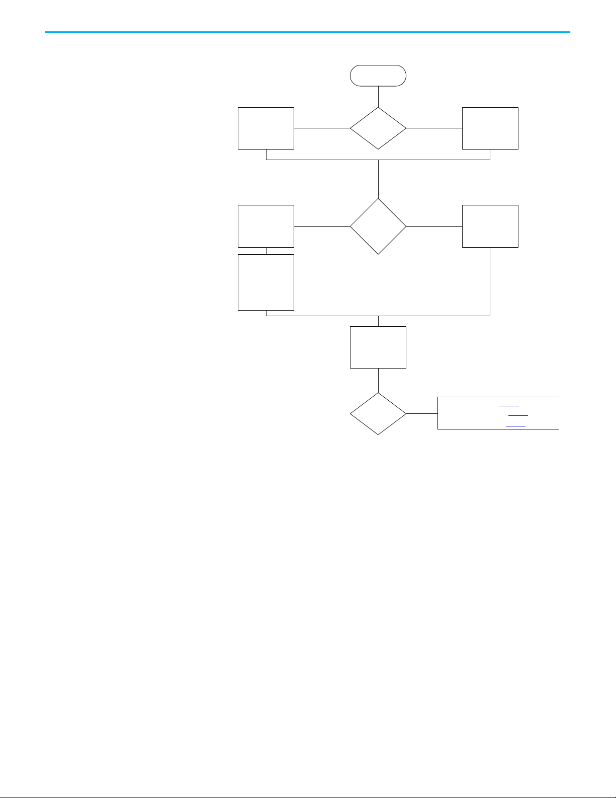
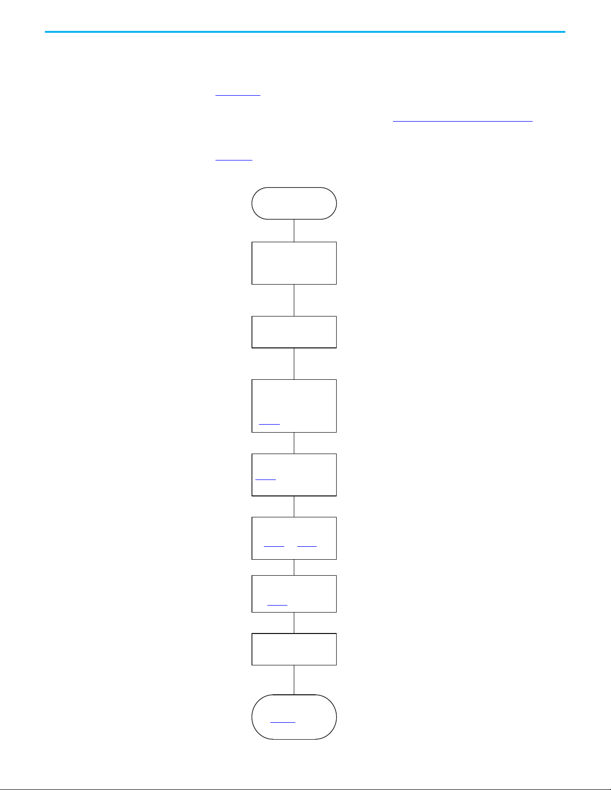
Figure 1 - Create a Motion Project
Controller Project
Enable Time
Synchronizaon
Is this a safety
applicaon?
Integrated safety
controller
Standard
controller
Does the
controller need
an EtherNet/IP
device?
Add the
EtherNet/IP
device to the
project
Use the embedded
EtherNet/IP
connecvity in the
controller
Add a Drive or
iTRAK system
For Kinex drives, see pg
For PowerFlex drives, see pg
For iTRAK systems, see pg
Set Exact Keying
to
Exact Match or
Compable Keying
on the Module
Definion dialog
box.
yes
no
yes
no
Check Enable Time Synchronizaon
on
the Date/Time tab of the Module
Properes dialog box.
Choose Time Sync and Moon as the
Time Sync Connecon type on the
Module Definion dialog box.
For Kinetix Drives, see page 18
For PowerFlex Drives, see page 19
For iTRAK® systems, see page 21
Chapter 2 Configure Drive Properties
Rockwell Automation Publication MOTION-UM003L-EN-P - November 2020 17
Page 18
Chapter 2 Configure Drive Properties
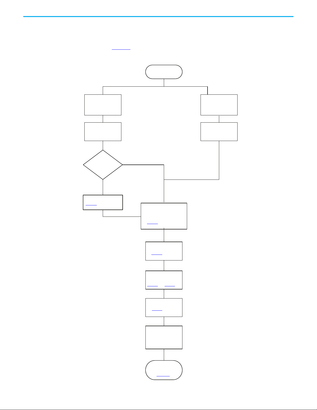
Controller Project Ready
Controller EtherNet/IP Connectivity Time
Synchronization
Add a Kinetix Drive to
your EtherNet/IP
Network
Configure General Settings
Configure Drive Settings
in the Module Definition
Dialog Box
page 23
Type a Name and IP Address of the
drive on the General page of the
Module Properties dialog box.
Configure power settings
page 26
Configure Digital
Inputs and Outputs
page 29
and page 31
Configure Safety
Connections
page 31
Configure Motion Safety
or Drive Safety
Configure Axis Properties
See Chapter 3
See your Drive User Manual for
details on configuring your drive
safety options.
Add a Kinetix Drive The available configuration options differ depending on the controller and
drive type you chose for your project. Before you begin, verify that you have the
correct minimum software, firmware, and Add-on Profile versions. See
Chapter 1.
Refer to the drive manuals, listed in the Additional Resources on page 9, for
detailed information on drive configuration and operation.
Figure 2
shows the path for configuring a Kinetix drive in a motion project.
Figure 2 - Add and Configure a Kinetix Drive
18 Rockwell Automation Publication MOTION-UM003L-EN-P - November 2020
Page 19
Chapter 2 Configure Drive Properties
Controller Project Ready
Add PowerFlex 755 Drive
to your
EtherNet/IP Network
Add PowerFlex 527
Drive to your
EtherNet/IP Network
Configure General
Settings
Configure General
Settings
Do you need I/O
or feedback?
Type a Name and IP Address
of the drive on the General
page of the Module
Properties dialog box.
Choose a PowerFlex 755
drive catalog number that
ends in -CM or -CM-Sx for an
Integrated Motion Drive.
Add a peripheral device
page 20
Configure drive settings
in the Module Definition
dialog box
page 23
Configure power
page 26
Configure
Motion Safety
Configure Safety
page 31
Configure digital inputs
and outputs
page 29
and page 31
See your Drive User Manual for
details on configuring your drive
safety options.
Configure Axis
Properties
See Chapter 3
Add a PowerFlex Drive The available configuration options differ depending on the controller, drive
type, and PowerFlex option modules you chose for your project.
yes
Figure 3
shows the path for configuring a PowerFlex drive in a motion project.
Figure 3 - Add and Configure a PowerFlex 755 or PowerFlex 527 Drive
no
Rockwell Automation Publication MOTION-UM003L-EN-P - November 2020 19
Page 20
Chapter 2 Configure Drive Properties
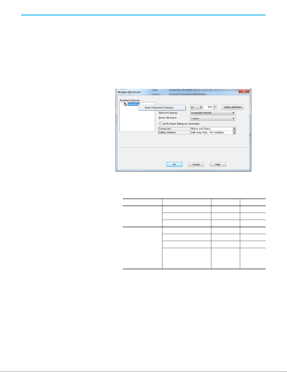
Add a Peripheral Device for PowerFlex 755 Drives
To add a peripheral device to your drive for I/O or feedback, follow these steps.
1. On the General tab of the Module Properties dialog box, click Change to
open the Module Definition dialog box.
2. Edit the Revision, if necessary.
For PowerFlex 755 drives, you must select a revision of 12 or later to add
an I/O module to port 7 as a peripheral device.
3. Right-click your drive and choose New Peripheral Device.
4. Select a port for your device.
These feedback module combinations that are supported.
Option Supported Module Catalog Number Valid Ports
Single Incremental Encoder 20-750-ENC-1 4…8
Two Feedback Options
Two Feedback Options
and One Safety Option
(1) The safe speed monitor option module must be used with the 20-750-DENC-1 Dual Incremental Encoder module
or the 20-750-UFB-1 Universal Feedback module.
Dual Incremental Encoder 20-750-DENC-1 4…8
Universal Feedback Card 20-750-UFB-1 4…6
Single Incremental Encoder 20-750-ENC-1 4 and 5
Dual Incremental Encoder 20-750-DENC-1 4 and 5
Universal Feedback 20-750-UFB-1 4 and 5
Safe Torque Off, or
Safe Speed Monitor
Integrated Safe Torque Off, or
Integrated Safety Functions
(1)
, or
20-750-S
20-750-S1
20-750-S3
20-750-S4
6
5. If you will be using a feedback option module for safe feedback with a 20750-S4 safety option, click the Safe Feedback checkbox.
20 Rockwell Automation Publication MOTION-UM003L-EN-P - November 2020
Page 21

Chapter 2 Configure Drive Properties
6. If your drive is equipped with an integrated safety option module (20750-S3 or 20-750-S4), click Safety Definition to define the Major and
Minor Revisions and Electronic Keying options.
When you are using integrated safety modules, you can set the electronic
keying to either Exact Match or Compatible Keying.
7. Continue with Configure Module Definition
on page 23.
Add an iTRAK Section, Mover, or Power Supply
The available configuration options differ depending on the controller, and
iTRAK device type you chose for your project. Before you begin, verify that you
have the correct minimum software, firmware, and Add-on Profile versions.
See Chapter 1.
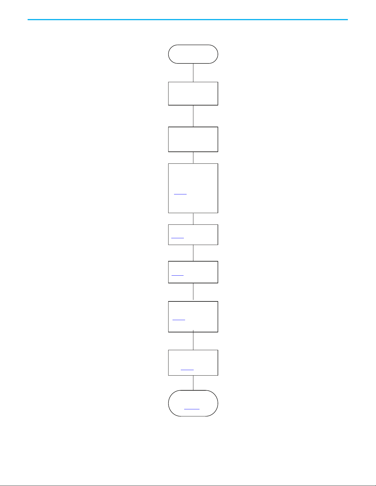
Figure 4 shows the path for configuring an iTRAK section, mover, or power
supply in an integrated motion project.
If you are using an iTRAK power supply, add the module to the project under
the same controller as the iTRAK sections and the Kinetix 5700 power supply
(either the regenerative power supply or the DC Bus supply).
If using the iTRAK system, each section is automatically assigned an IP
address by the iTRAK backplane, in sequential order from the first iTRAK
module added to the project.
Rockwell Automation Publication MOTION-UM003L-EN-P - November 2020 21
Page 22
Chapter 2 Configure Drive Properties
Controller Project Ready
Controller EtherNet/IP
connectivity Time
Synchronization
If you have an iTRAK power supply,
add the drive under the same
controller as the iTRAK section and
Kinetix 5700 power supply.
Type a Name and IP Address of the
drive on the General page of the
Module Properties dialog box.
Add iTRAK Drive
Configure General
Settings
Configure safety page
page 31
Configure power page
page 26
Configure drive
settings in the Module
Definition dialog box
page 23
Configure Motion Safety
page 26
See your iTRAK user manual for
details on configuring your motion
safety options.
Configure track
sections
page 35
Configure Axis
Properties
See Chapter 3
Figure 4 - Add iTRAK Drive Modules
22 Rockwell Automation Publication MOTION-UM003L-EN-P - November 2020
Page 23
Chapter 2 Configure Drive Properties
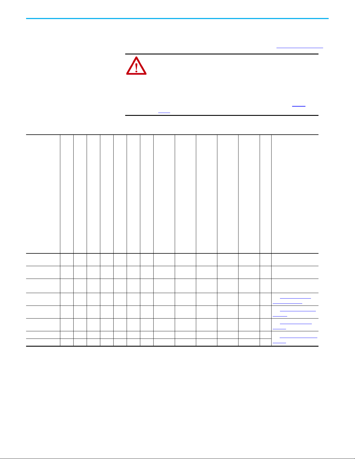
Configure Module Definition All drives let you update the drive Revision, choose an Electronic Keying type,
and choose a Power Structure. Options for Connection type and other fields
depend on the type of drive you added to your project. See Table 3 on page 23
ATTENTION: The electronic keying feature automatically compares the
expected module, as shown in the configuration tree, to the physical
module before communication begins.
When you are using devices in an integrated motion application, set the
electronic keying to either Exact Match or Compatible Keying.
Never use Disable Keying with motion or safety modules.
For more information about electronic keying, see the Electronic Keying in
Logix 5000™ Control Systems Application Technique, publication LOGIX-
AT001.
Table 3 - Module Definition Fields
.
Kinetix 350
Kinetix 5300
Kinetix 5500
Kinetix 6500
Kinetix 5700 DC - Bus Supply
Kinetix 5700 Regenerative Bus Supply
Kinetix 5700 Inverter
PowerFlex 755 Drive with Embedded Ethernet
PowerFlex 755 Hi-Power Drive with Embedded Ethernet
PowerFlex 755 Drive with Safe Torque Off
PowerFlex 755 Hi-Power Drive with Safe Torque Off
(with 20-750-S option module installed)
PowerFlex 755 Drive with Safe Speed Monitoring
PowerFlex 755 Hi-Power Drive with Safe Speed Monitoring
(with 20-750-S1 option module installed)
PowerFlex 755 Drive with Integrated Safe Torque Off
PowerFlex 755 Hi-Power Drive with Integrated Safe Torque Off
(with 20-750-S3 option module installed)
PowerFlex 755 Drive with Integrated Safety Functions
PowerFlex 755 Hi-Power Drive with Integrated Safety Functions
(with 20-750-S4 option module installed)
PowerFlex 527 Drive
Revision XXXXXX
Electronic KeyingXXXXXXXXXXXXX
Power StructureXXXXXXXXXXXXX
Safety Application X
ConnectionXXXXXXXXXXXXX
Safety Instance X X
Motion Safety 1 X
Motion Safety 2 X
(1) For 2198-xxxx-ERS3 series A drives, the firmware revision is 7 or earlier. For 2198-xxxx-ERS3 series B, drives, the firmware versions is 9 or later.
(2) For PowerFlex 755 drives, you must select a revision of 12 or later to add an I/O module to port 7 as a peripheral device.
(3) Locate the power stucture reference numbers by checking the device hardware, reviewing the product documentation, checking the purchase order, or reviewing the bill of materials.
(1)X(2)
X
(2)
X
(2)
X
(2)
X
(2)
X
Update the Revision, if
X
necessary.
Choose Exact Match or
Compatible Keying.
Assign a power structure,
if necessary.
See Safety Application
Types on page 24
See Connection Types on
page 25.
See Safety Instance on
page 25
See Motion Safety Type
page 26
(3)
on
Rockwell Automation Publication MOTION-UM003L-EN-P - November 2020 23
Page 24
Chapter 2 Configure Drive Properties
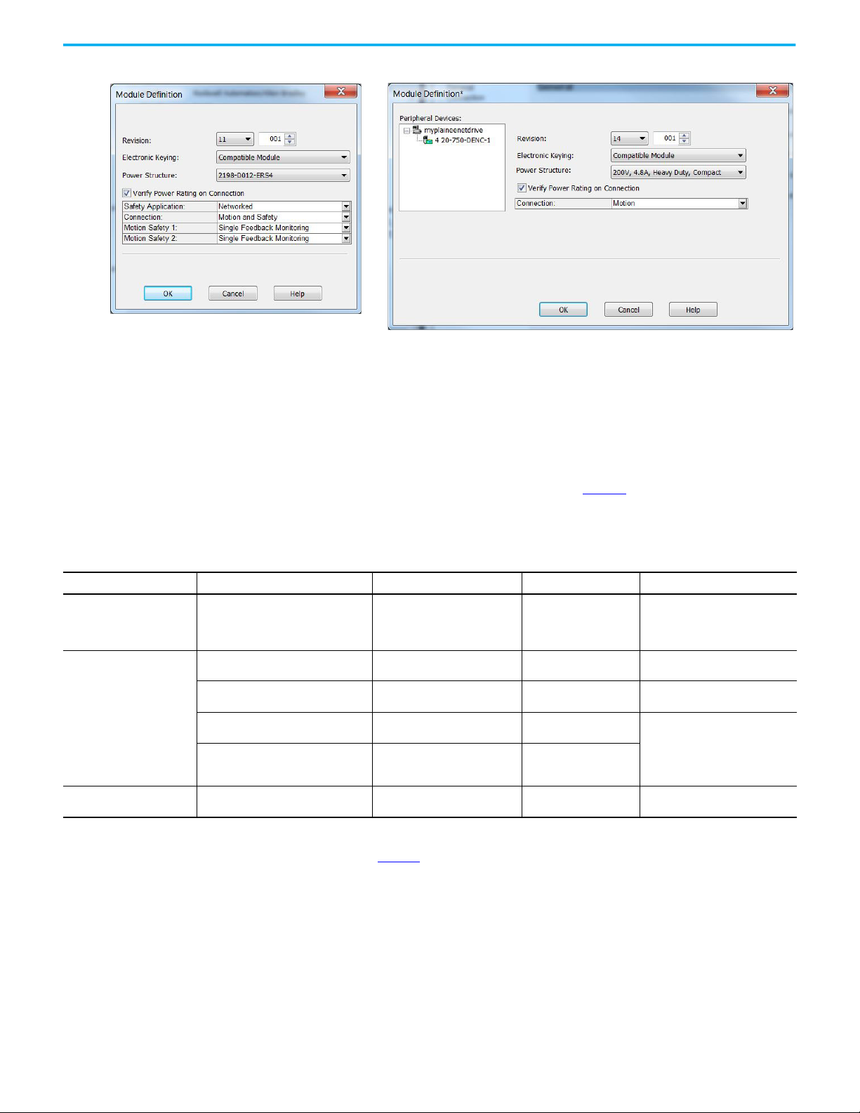
Kinetix 5700 Drive with Integrated Safety
PowerFlex 755 Drive with Embedded Ethernet
Figure 5 - Example Module Definition Dialog Boxes
Safety Application Types
The Safety Application pull-down menu lets you choose between Hardwired
for Hardwired STO mode or Networked for a Kinetix 5700 integrated safety
application or iTRAK 5730 integrated safety. Table 4
defines the choices and
which Connection Types are available based on your choice of Safety
Application mode.
Table 4 - Safety Application Definitions
Safety Application Mode Safety Functions
Hardwired Safe Torque-off (STO)
Safe Torque-off (STO) 2198-xxxx-ERS3 (series A)
Safe Torque-off (STO) 2198T-L20-T03
Networked (integrated)
Safety Off
(1) Where a 2198-xxxx-ERS3 drive is specified, a 2198-xxxx-ERS4 drive is backwards compatible. Where a 2198-xxxx-ERS3 (series A) drive is specified, a 2198-xxxx-ERS3 (series B) drive is backwards
compatible.
(2) See the Kinetix 5700 Safe Monitor Functions Safety Reference Manual, publication 2198-RM001
Timed SS1
• Timed SS1
• Monitored SS1
• Controller-based safety functions
•none
Minimum Module
2198-xxxx-ERS3 (series A)
2198-xxxx-ERS3 (series B)
2198-xxxx-ERS3 (series B)
2198T-L20-T03
2198-xxxx-ERS4
(2)
iTRAK 5730
(1)
Required
, for more information on these Drive Safety instructions.
Connection Types Compatible Controllers
• Motion Only • ControlLogix® 5570/5580
• Motion and Safety
•Safety Only
• Motion and Safety
•Safety Only
• Motion and Safety
•Safety Only
• Motion and Safety
•Safety Only
• Motion Only • ControlLogix 5580
• CompactLogix 5370/5380
• GuardLogix 5570/5580
• Compact GuardLogix 5370/5380
• GuardLogix 5570/5580
• GuardLogix 5580
• GuardLogix 5580
• Compact GuardLogix 5380
• GuardLogix 5580
24 Rockwell Automation Publication MOTION-UM003L-EN-P - November 2020
Page 25

Chapter 2 Configure Drive Properties
Connection Types
Choose the connection type for your drive.
Table 5 - Module Connection Definitions
Connection Type Used with the follow safety options Description
Motion and Safety • Integrated safety • Motion connections and integrated safety are managed by this controller.
Motion Only
Safety Only
• Hardwired Safe Torque Off mode
• Integrated safety, if there is a secondary safety
controller
• Integrated safety • Integrated safety is managed by this controller.
• Motion connections are managed by this controller.
• Hardwired STO is controlled by the hardwired safety inputs or integrated safety is managed by
another controller that has a Safety-only connection to the drive.
• Motion connections are managed by another controller that has a Motion only connection to the
drive.
For Motion and Safety or Safety selections, additional configuration and
considerations not covered in this manual apply. See the publications for
your drive, PowerFlex 750-series safety option module, and safety
controller, which are listed in the Additional Resources
Safety Instance
on page 9.
For PowerFlex drives with a 20-750-S4 option module installed and a
connection type of Motion and Safety or Safety only, you can choose a Safety
Instance.
Table 6 - Safety Instance Definitions
Safety Instance Mode Description
Safe Stop Only - No Feedback STO function and Timed SS1 Safe Stop functions are available.
Single Feedback Monitoring Primary feedback is used in the safety object for safe monitoring.
In addition to primary feedback, an external feedback device is used to provide
Dual Feedback Monitoring
error checking of the primary feedback device. A secondary encoder is
considered part f the encoder diagnostics and the data it produces is not rated
safety data.
Rockwell Automation Publication MOTION-UM003L-EN-P - November 2020 25
Page 26
Chapter 2 Configure Drive Properties
Motion Safety Type
When the Connection type is Motion and Safety or Safety only and the Safety
Application mode is Networked, you can choose a Motion Safety Type.
Table 7 - Motion Safety Definitions
Motion Safety Mode Description
STO Only 2198-xxxx-ERS3 (series A and B): STO function only.
2198-xxxx-ERS4: STO function and Timed SS1 Safe Stop functions are available.
Safe Stop Only - No Feedback
Single Feedback Monitoring
Dual Feedback Monitoring
See the Kinetix 5700 Safe Monitor Functions Safety Reference Manual,
publication 2198-RM001
device or two feedback devices.
2198-xxxx-ERS3 (series B): STO function and Timed SS1 Safe Stop functions are
available.
iTRAK 5730: STO function and Timed SS1 Safe Stop functions are available.
Primary feedback is used in the safety object for safe monitoring. The feedback can be
a SIL rated Hiperface DSL encoder, for example, a VPL-B1003P-Q or W motor used in
the DSL Feedback port. This can also be a Sine/Cosine or EnDat device, for example, an
MPL-B310P-M motor used in the Universal Feedback port.
In addition to primary feedback, an external feedback device is used to improve SIL
levels. For example, the Bulletin 842HR type encoder can be used in the Universal
Feedback port as a Sine/Cosine device.
, to evaluate SIL levels possible with a single feedback
Configure Power Settings The Power page lets you configure the drive Bus Configuration, assign a Bus
Sharing Group, set Bus Regulator Action or select a Shunt Resistor Type and
configuration limits. The options for configuration differ depending on drive
type.
Consider the following when choosing the appropriate settings for your
application.
• The Logix Designer application enforces shared-bus configuration rules
for Kinetix drives, except for shared AC configurations.
ATTENTION: To avoid damage to equipment all modules that are
physically connected to the same shared-bus connection system must be
part of the same bus-sharing Group in the Studio 5000 Logix Designer
application.
• Kinetix 5500 drives with single-phase operation is limited to 2198-H003ERSx, 2198-H008-ERSx, and 2198-H015-ERSx.
• Single-phase operation is possible only when Module Properties > Power
tab > Bus Configuration is configured as Standalone and Voltage is
configured as 200…240V AC.
ATTENTION: To avoid damage to equipment, make sure the AC input
voltage that is configured in the Logix Designer application matches the
actual hardware being configured.
26 Rockwell Automation Publication MOTION-UM003L-EN-P - November 2020
Page 27
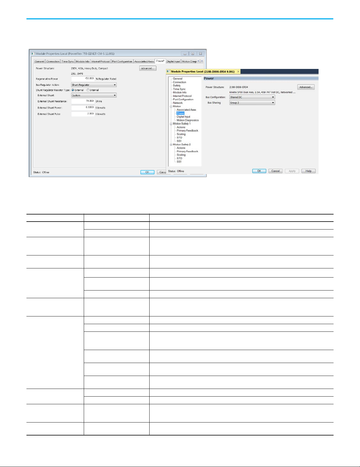
Figure 6 - Power Configuration Example Pages
PowerFlex 755 Drive
Kinetix 5700 Drive
Chapter 2 Configure Drive Properties
Table 8 - Power Settings
Attribute Settings Description
Volt age
PWM Frequency
AC Input Phasing
Bus Configuration
Bus-sharing Group
Bus Regulator Action
Shunt Regulator Resistor Type
External Shunt
External Shunt Resistance
1. Choose the appropriate power settings for your application.
400-480 VAC 324…528 AC rms input voltage
200-240 VAC 195…264 AC rms input voltage
2 kHz
4 kHz (Default)
8 kHz
• Three Phase
• Single Phase
Shared AC/DC
(1)
Standalone
Shared DC Applies to inverter drives with Shared DC input (common-bus) configurations.
(2)
•Group1
•Group2
•Group3
Disabled Disables the internal shunt resistor and external shunt option.
Shunt Regulator Enables the internal and external shunt options.
Adjustable Frequency
(3)
Shunt then Adjustable Frequency
Adjustable Frequency then Shunt
Common Bus Follower
(4)
Internal Enables the internal shunt (external shunt option is disabled).
External Enables the external shunt (internal shunt option is disabled).
•None
• Shunt catalog number
(5)
•Custom
Valid values are determined by the
type of drive.
The value sets the carrier frequency for the Pulse Width Modulation (PWM) output to the motor.
Input power phasing. Single phase operation is not available for all drives. For more information on the
power options that are available, see the user manual for your product.
Applies to 2198-Pxxx DC-bus power supply (converter) modules.
Applies to single-axis drives and drives with Shared AC input configurations.
Indicates that the converter section of the drive supplies DC Bus power only to this drive's power structure.
Applies to any bus-sharing configuration.
This selection allows the drive to either change the torque limits or ramp rate of the velocity to control the
DC bus voltage. This option is not recommended for positioning applications because it will override the
velocity and the system can overshoot or may not stop.
This selection allows the Shunt resistor to absorb as much energy as it is designed for, then transitions to
adjustable frequency control if the limit of the resistor has been reached.
This selection allows for adjustable frequency control of the DC bus. If adjustable frequency control cannot
maintain the DC bus within limits, the shunt resistor will be activated.
To configure your Kinetix 6500 IAM power module as a common-bus follower IAM
module.
Selects external shunt option.
Specifies the external shunt resistance in Ohms. Available only if External Shunt is set to Custom.
Rockwell Automation Publication MOTION-UM003L-EN-P - November 2020 27
Page 28
Chapter 2 Configure Drive Properties
PowerFlex 755 Drive
Kinetix 5700 DC Bus Supply
Table 8 - Power Settings
Attribute Settings Description
External Shunt Power
External Shunt Pulse Power
Bus Capacitance
(1) Shared AC/DC bus configuration is the default selection for 2198-Pxxx DC-bus power supplies.
(2) For more information on bus-sharing groups, refer to Kinetix 5700 servo drives User Manual, publication 2198-UM002
(3) Default for PowerFlex 527 drives.
(4) Drive will not accept CommonBus Follower selection while three-phase power or DC bus power is applied.
(5) Only the shunt catalog number intended for the specific DC-bus power supply is shown. See the Kinetix Servo Drives Specifications Technical Data, publication KNX-TD003
shunt resistors.
Valid values are determined by the
type of drive.
Valid values are determined by the
type of drive.
Valid values are determined by the
type of drive.
Specifies the external shunt power in Kilowatts. Available only if External Shunt is set to Custom.
Specifies the external shunt power in Kilowatts. Available only if External Shunt is set to Custom.
Specifies the bus capacitance in microfarads (uF). Available only if External Shunt is set to Custom.
.
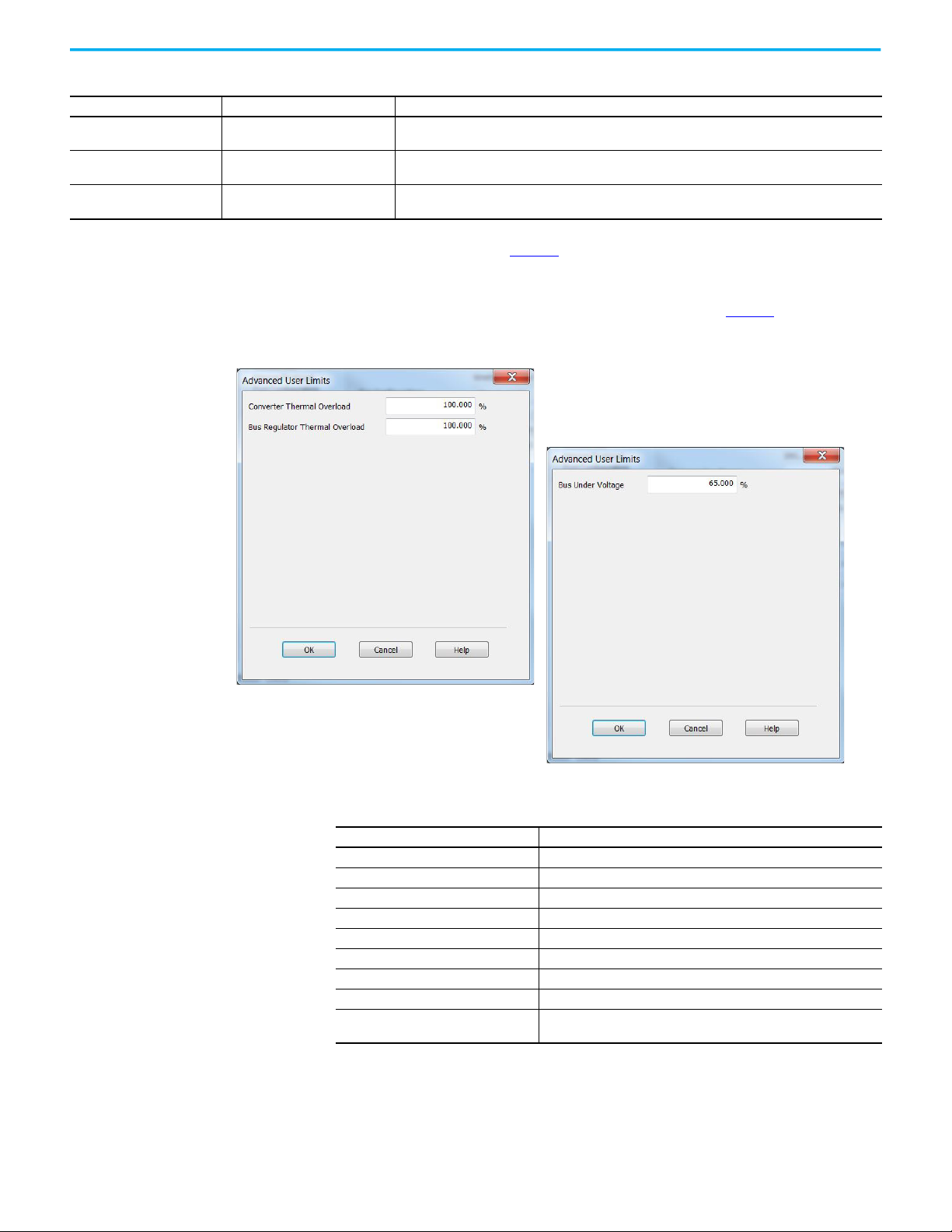
2. Click Advanced to adjust the limits for overload and voltage.
, for more information on
Table 9 - Limits for Overload and Voltage
Parameter Description
Converter Over Temperature Limit Sets the user limit for converter over temperature.
Converter Thermal Overload Limit Sets the user limit for converter thermal overload.
Converter Pre-charge Overload Limit Sets the user limit for converter pre-charge overload.
Converter Ground Current Limit Sets the user limit for the converter ground current.
Bus Regulator Over Temperature Limit Sets the user limit for bus regulator temperature.
Bus Regulator Thermal Overload Limit Sets the user limit for bus regulator overload.
Bus Over Voltage Limit Sets the user limit for bus over voltage.
Bus Under Voltage Limit Sets the user limit for bus under voltage.
Control Module Over Temperature Limit
28 Rockwell Automation Publication MOTION-UM003L-EN-P - November 2020
Sets the user limit for the Control Module Over temperature User Limit
exception.
Page 29

Chapter 2 Configure Drive Properties
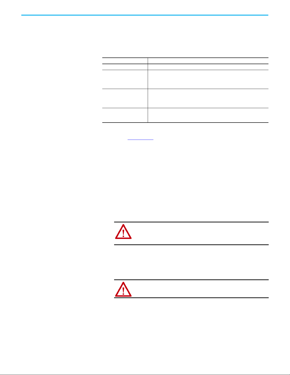
Configure Digital Inputs The following restrictions apply to settings made on this page:
• All digital input parameters, except Unassigned, must be unique.
• At least one Digital Input must be set to Regeneration OK when a module
is set to the Shared DC - Non-CIP Converter bus sharing configuration in
the Power tab.
• When you use the 2198-R014, 2198-R031, or 2198-R127 external passive
shunt resistor with a DC-bus power supply, the Shunt Thermal Switch
Digital Input must be configured.
Configure the digital inputs to monitor the status of drive functions
appropriate to your application.
Table 10 - Drive Functions
Functions Description
Enable A 24V DC input is applied to this terminal as a condition to enable each module.
Home
Registration 1
Registration 2
Home
Positive Overtravel
Negative Overtravel
Regeneration OK
AC Line Contactor OK An active indicates that the AC Line Contactor is working correctly.
Bus Capacitor OK
Shunt Thermal Switch OK
An active state indicates to a homing sequence that the referencing sensor as been
seen. Typically, a transition of this signal is used to establish a reference position for the
machine axis.
An inactive-to-active transition (also known as a positive transition) or active-to-inactive
transition (also known as a negative transition) is used to latch position values for use in
registration moves.
An active state indicates to a homing sequence that the referencing sensor has been
seen. Typically, a transition of this signal is used to
establish a reference position for the machine axis.
The positive/negative limit switch (normally closed contact) inputs for each axis require
24V DC (nominal).
In the active state the inverters can be enabled. An inactive state indicates that the bus
supply unit is not ready to supply DCbus
power. The inverters cannot be enabled.
When a Kinetix 5700 bus group is supplied by an 8720MC-RPS unit, one inverter in the
bus group must be configured in the Logix Designer application as Shared-DC Non-CIP
Motion™ Converter and assigned to Regeneration OK. This signal is wired from RDY on
the 8720MC-RPS unit and indicates to the Kinetix 5700 drive system that the 8720MC-RPS
unit is ready to supply power. Enabled inverters enumerate a Bus Power Sharing fault if
the Regeneration OK input goes inactive.
You can configure this input in the Logix Designer application and wire the module
status (MS) output from the 2198-CAPMOD-2240 capacitor module to indicate to the
inverter that a major fault is present on the capacitor module.
When the 2198-R014, 2198-R031, or 2198-R127 external shunt resistor is wired to the DCbus power supply, this input must be
configured in the Logix Designer application to monitor the status of the external shunt
module thermal switch and assigned to Shunt
thermal switch OK. This function does not apply to the 2198-R004 shunt resistor. You can
also use this input to monitor the status of an
active shunt module in the system that is connected via the capacitor module or an
extension module.
Rockwell Automation Publication MOTION-UM003L-EN-P - November 2020 29
Page 30

Chapter 2 Configure Drive Properties
Table 10 - Drive Functions
Functions Description
u can configure this input in the Logix Designer application and wire the module
Yo
Bus Conditioner OK
Pre-charge OK
Motor Thermostat OK
status (MS) output from the 2198-DCBUSCONDRP312
conditioner module to indicate to the inverter that a major fault is present on the
conditioner module.
This feature extends the precharge input monitoring capability to the PowerFlex
755 drive in integrated motion. The event processing is as follows:
1. If the configured Pre-charge OK Input becomes inactive and the drive is in the
Stopped state, the drive enters the precharge state.
2. If the configured Pre-charge OK input becomes inactive and the drive is in the
Running state, the drive generates the Converter Pre-charge Input Deactivated
exception and performs a Fault Coast Stop.
Motor thermostat input functionality is provided through the motor thermostat
input (PTC) on the 22-Series I/O modules (installed in Port 7) when in Integrated Motion
on EtherNet/IP mode.
The functionality is the same as the motor thermostat functionality in parameter
mode. When the PTC input resistance transitions from low to high at the design
temperature, the drive issues a motor over temperature fault, 18 [Motor PTC Trip].
The functionality supports the current motor thermostat range for status trip and
reset in parameter mode. However, this functionality is not suitable for AllenBradley MPL and MPM motors due to the varying hardware capacities and thermostat
ranges of the Kinetix and 22-Series I/O modules.
30 Rockwell Automation Publication MOTION-UM003L-EN-P - November 2020
Page 31

Chapter 2 Configure Drive Properties
Configure Digital Outputs The Digital Outputs tab is only available for PowerFlex 755 drives with a digital
I/O option card installed as a peripheral device. The appearance of the tab
varies depending on the device configuration.
Configure the digital outputs appropriately for your application.
Table 11 - Digital Output Functions
Functions Description
Unassigned The output is not assigned.
A Contactor Enable Output can be configured in the PowerFlex 755 drive in
integrated motion only. The operation of this output is tied to fault processing in
Contactor Enable
Mechanical Brake Engage Delay
the drive. The drive de-energizes the Contactor Enable Output when an
exception causes the axis to go to the ‘shut down’ state.
Note: This configuration is only valid when an auxiliary power supply is used for
control power with frames 1…7 drives or when a 24 auxiliary power supply is
used on frames 8…10 drives.
The amount of time that the power structure remains enabled after the axis has
been commanded to zero speed before disabling the power structure. The
motor decelerates to a stop, the brake output actuates, and this delay provides
time for the brake to engage.
Configure Safety Settings If your system includes a drive that supports integrated safety, note the safety
network number (SNN) on the Module Properties General page, which
populates automatically when you add a drive that supports integrated safety
to the project.
Safety network numbers for PowerFlex drives that include 20-750-S3 or 20750-S4 option modules are unique. SNNs for other drives match the SNN of
the safety controller in the project.
Often the automatically-assigned SNN is sufficient, but sometimes manual
manipulation of the SNN is required. See Generate an SNN on page xx
for
more information.
The connection between the owner controller and the drive is based on the
following:
• Servo drive safety network number
•GuardLogix slot number
• GuardLogix safety network number
• Path from the GuardLogix controller to the 2198-xxxx-ERSx drive
• Configuration signature
Rockwell Automation Publication MOTION-UM003L-EN-P - November 2020 31
Page 32

Chapter 2 Configure Drive Properties
If any differences are detected, the connection between the GuardLogix
controller and drive is lost, and the yellow yield icon appears in the controller
project tree after you download the program.
Configure Safety Connections
1. Choose the Safety page.
2. Click Advanced to open the Advanced Connection Reaction Time Limit
Configuration dialog box.
32 Rockwell Automation Publication MOTION-UM003L-EN-P - November 2020
Page 33

Chapter 2 Configure Drive Properties
3. Analyze each safety channel to determine the appropriate settings.
The smallest Input RPI allowed is 6 ms. The selection of small RPI values
consumes network bandwidth and can cause spurious trips because
other devices cannot get access to the network.
For more information about the Advanced Connection Reaction Time
Limit Configuration, refer to the appropriate GuardLogix or Compact
GuardLogix Controllers User Manual, which is listed in Additional
Resources on page 9.
Generate the Safety Network Number (Integrated safety drives only)
The assignment of a time-based safety network number (SNN) is automatic
when you create a GuardLogix safety controller project and add new Safety
devices. This number is generally sufficient. However, manual manipulation of
an SNN is required in the following situations:
• If safety consumed tags are used
• If the project consumes safety input data from a device whose
configuration is owned by some other device
• If a safety project is copied to another hardware installation within the
same routable safety system
If an SNN is assigned manually, the SNN has to be unique.
IMPORTANT
If you assign an SNN manually, make sure that the system expansion does
not result in duplication of SNN and node address combinations.
A warning appears if your project contains duplicate SNN and node address
combinations. You can still verify the project, but Rockwell Automation
recommends that you resolve the duplicate combinations.
Rockwell Automation Publication MOTION-UM003L-EN-P - November 2020 33
Page 34

Chapter 2 Configure Drive Properties
To edit the SNN, follow these steps.
1. To open the Safety Network Number dialog box, click the ellipsis to the
right of the Safety Network Number.
2. Select either Time-based or Manual.
If you select Manual, enter a value from 1…9999 decimal.
3. Click Generate.
4. Click OK.
34 Rockwell Automation Publication MOTION-UM003L-EN-P - November 2020
Page 35

Chapter 2 Configure Drive Properties
Configure Track Sections For iTRAK drive modules, follow the steps below to configure your track.
1. From the Track ID pull down menu, select your Track ID.
When multiple modules share the same Track ID, these modules are
identified as being configured as a single Track System. This allows Logix
Designer to validate the track system as a whole. Section modules that
specify a 0 or Not Specified Track ID are not validated because they are
treated as stand-alone sections when validating track systems.
2. From the Mover Axis Assignment Sequence pull-down menu, choose the
Mover Axis Assignment Sequence for your motion application.
Table 12 - Mover Axis Assignment Sequences
Mover Axis Assignment Sequence Description
Decreasing Position
Increasing Position
Decreasing Position from Reference Mover
Increasing Position from Reference Mover
Track section assigns movers on the track to axis instances in a sequence
starting with the mover with the highest position value as the first mover
followed by movers with decreasing position values.
Track section assigns movers on the track to axis instances in a sequence
starting with the mover with the lowest position value as the first mover
followed by movers with increasing position values.
Track section assigns movers on the track to axis instances in a sequence
starting with the mover electronically identified as the Reference Mover
followed by movers in the direction of decreasing position values relative to
the Reference Mover.
Track section assigns movers on the track to axis instances in a sequence
starting with the mover electronically identified as the Reference Mover
followed by movers in the direction of increasing position values relative to
the Reference Mover
Rockwell Automation Publication MOTION-UM003L-EN-P - November 2020 35
Page 36

Chapter 2 Configure Drive Properties
3. From the Section Motor pull-down menu, select the section motor
corresponding to your iTRAK drive module.
A curve section acts like three individual sections: Curve A, curve B and
curve C. Each of the three sections needs to be added as a separate drive
and configured individually.
• If your drive module is a Straight section then select a 2198T-L20-T0303A00-S2 section motor
• If your drive module is a Curve A section then select a 2198T-L20-T0309D18-S2-A section motor
• If your drive module is a Curve B section then select a 2198T-L20-T0309D18-S2-B section motor
• If your drive module is a Curve C section then select a 2198T-L20-T0309D18-S2-C section motor
4. Enter the length of your entire track (number of iTRAK modules x 0.3 m)
in the Track Length field.
36 Rockwell Automation Publication MOTION-UM003L-EN-P - November 2020
Page 37

Configure Axis Properties
Topic Page
Create an Associated Axis 37
Create a Motion Group 40
Associate Axes to the Motion Group 43
Configure an Axis and Control Mode 43
Specify the Motor Data Source 49
Display Motor Model Information 53
Use Motor Analyzer 54
Assign Motor Feedback 55
Configure Load Feedback 59
Configure Master Feedback 60
Configure Actions 60
Configure Exceptions 62
Chapter 3
Create an Associated Axis Before you can complete the configuration process, you need to create an axis
and associate it to your drive.
Create an Axis
Follow these steps to create an axis.
1. To open the Module Properties dialog box, double-click the drive in the
Controller Organizer.
Rockwell Automation Publication MOTION-UM003L-EN-P - November 2020 37
Page 38

Chapter 3 Configure Axis Properties
PowerFlex® 755 Drive
Kinetix® 5700 Drive
2. Click the Associated Axes tab.
3. Click New Axis.
4. On the New Tag dialog box, type a name for the axis.
The default data type is AXIS_CIP_DRIVE.
For iTRAK® systems, the first axis must be the section axis. The
remaining four axis can be used for mover axis or left blank depending
on your application.
38 Rockwell Automation Publication MOTION-UM003L-EN-P - November 2020
Page 39

Chapter 3 Configure Axis Properties
5. Make any adjustments for your application.
6. Click Create.
7. Configure additional axes, if applicable.
Specify Feedback Assignments
The type of feedback you can assign differs based on the type of drive.
Table 13 - Drive Feedback Types
Drive Axis Feedback Types
Kinetix 350 1 Motor Feedback
Kinetix 5300 2
Kinetix 5500 1 Motor Feedback
Kinetix 6500 2
PowerFlex 527 1 Motor Feedback
Kinetix 5700 Single-axis Inverter (2198-Sxxx-ERSx) 2
Kinetix 5700 Dual-axis Inverter (2198-Dxxx-ERSx) 4
Kinetix 5700 DC Bus Power Supply
Kinetix 5700 Regenerative Power Supply
2198T iTRAK Power Supply 1 No Feedback
iTRAK 5370 Section 1 Integrated Track Feedback
iTRAK 5370 Mover 4 Integrated Track Feedback
PowerFlex 755 with 20-750-ENC-1 feedback module 1 Configure the Port channel A for Motor Feedback or Load Feedback
PowerFlex 755 with 20-750-DENC-1 feedback module
PowerFlex 755 with 20-750-UFB-1 feedback module
Axis 1 for Motor or Load Feedback
Axis 2 for Auxiliary (Master) Feedback
• Port 1 is reserved for Motor Feedback on the primary axis (Axis_1)
• Port 2 can be used either as Load Feedback for the primary axis or as a
Master Feedback for a secondary feedback only axis (Axis_2)
Axis 1 for Motor or Load Feedback
Axis 2 for Auxiliary (Master) Feedback
Axis 1 and 3 for Motor or Load Feedback
Axis 2 and 4 for Auxiliary (Master) Feedback
1 No Feedback
Configure the Port channel A and channel B for Motor Feedback or Load
1
Feedback
PowerFlex 755 requires a peripheral device for feedback. You must manually
establish the motor or load feedback port and channel assignments on the
PowerFlex 755 drive.
1. For PowerFlex 755 drive and Kinetix 5700 drive and Kinetix 6500 drives,
use the pull-down menus to choose the feedback type for the applicable
axes.
2. Click OK to close the Module Properties dialog box.
IMPORTANT
The Logix Designer application prevents the creation of feedback
port assignments with incompatible feedback types. For example,
you cannot assign the same port for multiple devices. The same port
cannot be used for Motor Feedback Device, Load Feedback Device,
and Master Feedback Device.
Rockwell Automation Publication MOTION-UM003L-EN-P - November 2020 39
Page 40

Chapter 3 Configure Axis Properties
Create a Motion Group All axes must be added to the Motion Group in your project. If you do not
group the axes, they remain ungrouped and unavailable for use. You can only
have one Motion Group per Logix controller.
To create a motion group, follow these instructions.
1. In the Controller Organizer, right-click Motion Groups and choose New
Motion Group.
2. Type a name for the motion group.
3. Make any adjustments for your application.
4. Click Create.
40 Rockwell Automation Publication MOTION-UM003L-EN-P - November 2020
Page 41

Chapter 3 Configure Axis Properties
Set the Base Update Period
The Base Update Period is basically the RPI rate for Ethernet communication
between the controller and the motion module, a Unicast connection.
There are two alternate update periods that you can configure when using the
Axis Scheduling function. See Axis Scheduling Configuration
details.
The Base Update Period determines how often the Motion Task runs. When
the Motion Task runs, it interrupts most other tasks regardless of their
priority. The Motion Task is the part of the controller that takes care of
position and velocity information for the axes.
To set the Base Update Period, follow these steps.
1. Click the Attribute tab in the Motion Group Properties dialog box.
on page 68 for
Rockwell Automation Publication MOTION-UM003L-EN-P - November 2020 41
Page 42

Chapter 3 Configure Axis Properties
Motion Task
Scans of Your Code, System
Overhead, and so on
0 ms 10 ms
20 ms 30 ms 40 ms
In this example, the Base Update Period = 10 ms. Every 10 ms the controller stops scanning your code and whatever else it is doing and runs the motion
2. Set the Base Update Period.
Check the Last Scan time values. Typically, the value is less
than 50% of the Base Update Period.
Figure 7 - Base Update Period Example
The Base Update Period is a trade-off between updating positions of your axes
and scanning your code. In general, you do not want the Motion Task to take
more than 50% of the overall Logix controller time on average. The more axes
that you add to the Motion Group, the more time it takes to run the Motion
Task.
For detailed information on the Axis Scheduling function, Axis Assignment
tab, and Alternate Update Period Scheduling, see Axis Scheduling
Configuration on page 68.
42 Rockwell Automation Publication MOTION-UM003L-EN-P - November 2020
Page 43

Chapter 3 Configure Axis Properties
Associate Axes to the Motion Group
To associate axes to a motion group, follow these steps:
1. Right-click the new motion group and choose Properties.
2. Click the Axis Assignment tab and move your axes (created earlier) from
Unassigned to Assigned.
3. Click the Attribute tab and edit the default values as appropriate for your
application.
See Axis Scheduling and Faults for detailed information on the settings
available from the Attribute tab.
Configure an Axis and Control Mode
4. Click OK.
After you add the drive to your project and create the axes, use the Axis
Properties dialog boxes to complete the drive configuration. Notice that the
dialog boxes change based on your configuration choices.
Table 14
lists the basic tasks necessary configure an axis.
Table 14 - Axis Properties Pages
Axis Properties Page Perform These Tasks Page
• Assign the axis configuration.
• Choose the feedback configuration.
General
Motor
Motor Feedback • Select and configure the Motor Feedback Type. 55
Load Feedback • Select and configure the Load Feedback Type, if applicable. 59
Master Feedback
• Choose the application type, if applicable.
• Choose the loop response (low, medium, or high), if applicable.
• If you have not already done so, you can create and associate an axis to a new
Motion Group and associate a drive module to the axis.
• Specify a motor with the Data Source = Nameplate Datasheet.
• Specify a motor with the Data Source = Catalog Number.
• Select a motor with the Data Source = Motor NV.
• Only the Motor Overload Limit is configurable for iTRAK Sections
• Select and configure the Master Feedback Type, if applicable.
Master Feedback is only available for Feedback Only axes.
44
49
60
Rockwell Automation Publication MOTION-UM003L-EN-P - November 2020 43
Page 44

Chapter 3 Configure Axis Properties
Table 14 - Axis Properties Pages
Axis Properties Page Perform These Tasks Page
Actions
Exceptions
Scaling
• Configure how an axis responds to fault types.
• Modify actions for how an axis responds to fault types.
• Define the action to be performed by the drive as a result of an exception
condition. Exceptions are conditions that can occur during motion axis operation
that could generate faults or alarms.
• Configure feedback by choosing the load type, by entering the scaling units, and
by choosing the Travel mode.
• Enter the Input Transmission and Actuator ratio, if applicable.
60
62
137
The parameters that you configure on the General category dialog box result in
the presentation of attributes and parameters that are available for the
combination of your selections.
IMPORTANT
All AXIS_CIP_DRIVE Axis Properties dialog boxes are dynamic.
Optional attributes and dialog boxes that are related to each
integrated motion axis you create come and go based on what
combination of axis characteristics you define.
See the Integrated Motion Reference Manual, publication MOTION-RM003
,
for complete information on Axis Attributes and how to apply Control Modes
in the axis configuration.
IMPORTANT
Be sure to associate the drive and axis before when configuring
the axis because the drive determines what optional attributes
are supported for the axis.
If you have already created an axis and associated in with a drive, the
Associated Module and Axis are shown on the General page of the Axis
Properties dialog box.
Figure 8 - General Page
The Axis Number field corresponds to the axes listed on the Associated Axes
tab of the Module Properties dialog box. Any feedback port assignments that
you made on the Associated Axes page are also mapped to the drive when you
associate an axis and a drive.
44 Rockwell Automation Publication MOTION-UM003L-EN-P - November 2020
Page 45

Chapter 3 Configure Axis Properties
For more information on Control Modes, see the Integrated Motion Reference
Manual, publication MOTION-RM003
.
1. In the Controller Organizer, double-click the Axis that you want to
configure.
2. Choose an Axis Configuration type. For this example, choose Position
Loop.
Table 15
, Table 16, and Table 17 compare the axis configuration types
for Kinetix, PowerFlex, and iTRAK drives.
Table 15 - Compare the Axis Configuration Types for the Kinetix Drives
Axis Type
Position Loop (P) Yes Yes Yes Yes Yes No No Yes
Velocity Loop (V) Yes Yes Yes Yes Yes No No Yes
Torque Loop (T) Yes Yes Yes Yes Yes No No Yes
Feedback Only (E) No Yes Yes Yes Yes No No Yes
Frequency Control (F) No Yes Yes Yes Yes No No No
Regenerative Converters
(G)
Non-Regenerative
Converters (N)
Kinetix
350 Drive
No No No No No No Yes No
No No No No No Yes No No
Kinetix
5300
Drive
Kinetix
5500
Drive
Kinetix 5700 Dualaxis Inverter
Kinetix 5700 Singleaxis Inverter
Kinetix 5700 DC
Bus Supply
Kinetix 5700
Regenerative
Power Supply
Table 16 - Compare the Axis Configuration Types for the PowerFlex Drives
Axis Type PowerFlex® 527 PowerFlex 755
Position Loop (P) Yes Yes
Velocity Loop (V) Yes Yes
Torque Loop (T) No Yes
Feedback Only (E) No No
Frequency Control (F) Yes Yes
Kinetix
6500
Drive
Rockwell Automation Publication MOTION-UM003L-EN-P - November 2020 45
Page 46

Chapter 3 Configure Axis Properties
Table 17 - Compare the Axis Configuration Types for the iTRAK 5370
Axis Type iTRAK 5370 Sections iTRAK 5370 Movers
Position Loop (P) No Yes
Velocity Loop (V) No No
Torque Loop (T) No Yes
Feedback Only (E) No No
Frequency Control (F) No No
Track Section (X) Yes No
3. In the Feedback Configuration pull-down menu, choose Motor Feedback.
For iTRAK mover and section axes, the Feedback Configuration is always
Motor Feedback. Fot the iTRAK power supply it is always No Feedback.
See Table 18
and Table 19 for Kinetix and PowerFlex drive options,
respectively.
Table 18 - Feedback Configuration Types for Kinetix Drives
Feedback
Type
Motor
Feedback
Load Feedback —
Dual Feedback — Position Loop (P) — Position Loop (P) — — Position Loop (P)
Dual Integral — — — — — — —
Master
Feedback
No Feedback —
Kinetix 350 Kinetix 5300 Kinetix 5500
Position Loop (P),
Velocity Loop (V),
Torque Loop (T)
— Feedback Only (N) Feedback Only (N) Feedback Only (N) — — Feedback Only (N)
Position Loop (P),
Velocity Loop (V),
Torque Loop (T)
Position Loop (P),
Velocity Loop (V)
Velocity Loop (V),
Fre quency
Control (F)
Position Loop (P),
Velocity Loop (V),
Torque Loop (T)
—
Velocity Loop (V),
Frequency Control (F)
Kinetix 5700 Single
and Dual-axis
Inverter Type
Position Loop (P),
Velocity Loop (V),
Torque Loop (T)
Position Loop (P),
Velocity Loop (V)
Frequency Control (F)
Kinetix 5700 DC
Bus Supply
——
——
Non-regenerative
Converter Only (N)
Kinetix 5700
Regenerative
Power Supply
Regenerative
Converter (G)
Kinetix 6500
Position Loop (P),
Velocity Loop (V),
Torque Loop (T)
Position Loop (P),
Velocity Loop (V),
Torque Loop (T)
—
Table 19 - Feedback Configuration Types for PowerFlex Drives
Feedback Type PowerFlex 527 PowerFlex 755
Motor Feedback Position Loop (P), Velocity Loop(V)
Load Feedback — —
Dual Feedback — Position Loop (P)
46 Rockwell Automation Publication MOTION-UM003L-EN-P - November 2020
Position Loop (P), Velocity Loop(V),
Torque Loop (T)
Page 47

Chapter 3 Configure Axis Properties
Table 19 - Feedback Configuration Types for PowerFlex Drives
Feedback Type PowerFlex 527 PowerFlex 755
Dual Integral — Position Loop (P)
Master Feedback — —
No Feedback Frequency Control (F)
Velocity Loop (V),
Frequency Control (F)
4. Choose application type, if applicable.
Application Type specifies the type of motion control application and is used to
set the Gain Tuning Configuration Bits attribute that establishes the
appropriate gain set application. These combinations determine how the
calculations are made, which can reduce the need to perform an Autotune or a
Manual Tune.
Rockwell Automation Publication MOTION-UM003L-EN-P - November 2020 47
Page 48

Chapter 3 Configure Axis Properties
This table provides the gains that are established based on the application type.
Table 20 - Customize Gains to Tune
Application Type Kpi Kvi ihold Kvff Kaff torqLPF
(1)
Custom
Basic No No No Yes No Yes
Tracking No Yes No Yes Yes Yes
Point-to-Point Yes No Yes No No Yes
Constant Speed No Yes No Yes No Yes
(1) If you set the type to Custom, you can control the individual gain calculations by changing the bit settings in the Gain Tuning
Configuration Bits Attribute.
— ————
Include in the table that:
• Kpi = Position Integrator Bandwidth
• Kvi = Velocity Integrator Bandwidth
• iHold = Integrator Hold
• Kvff = Velocity Feedforward
• Kaff = Acceleration Feedforward
• torqLPF = Torque Low Pass Filter
5. Choose a loop response, if applicable.
Loop Response settings also impact the calculations that are made and can
minimize the need for you to perform an Autotune or a Manual Tune. The loop
response impacts the spacing between the position and velocity loops and the
proportional and integral gains. This response impacts how aggressively a
given profile is tracked.
For information about other application type and loop response
settings and attribute calculations, see the specific attribute
descriptions in the Integrated Motion on the EtherNet/IP Reference
Manual, publication MOTION-RM003.
6. Some drives let you enable or disable a Vertical Load Control function.
When this feature is Enabled, the drive attempts, whenever possible, to
avoid applying Category 0 stop actions in response to Major Fault
conditions. The drive may tailor other aspects of its behavior to best
handle vertical loads.
48 Rockwell Automation Publication MOTION-UM003L-EN-P - November 2020
Page 49

Chapter 3 Configure Axis Properties
7. For converters, specify a Converter Startup Method to indicate how the
axis transitions from the Stopped state to the Starting state.
Table 21 - Converter Startup Methods
Method Description
the converter stays in the Stopped state until it receives an Enable Request from the controller.
Enable Request
Enable Input
Automatic
After the converter receives the request, it transitions to Starting state and checks for proper
AC line synchronization. Once ready for regenerative control, the converter transitions to the
Running state with all configured control loops operational.
the converter checks the status of the Enable Input. If it is active, the converter axis transitions
from the Stopped state to the Starting state and checks for proper AC line synchronization.
Once ready for regenerative control, the converter transitions to the Running state with all
configured control loops operational.
the converter automatically transitions to Starting state and checks for proper AC line
synchronization. Once ready for regenerative control, the converter transitions to the Running
state with all configured control loops operational.
Specify the Motor Data Source
The Motor Data Source is where you tell the axis where the motor
configuration values are originating. You can select a motor by catalog number
from the Motion Database. You can enter motor data from a nameplate or data
sheet, or use the motor data that is contained in the drive or motor nonvolatile
memory.
On the Motor dialog box you specify what motor you want to use and where the
data is coming from:
• Specify a motor with the Data Source = Catalog Number.
(1)
• Specify a motor with the Data Source = Nameplate Datasheet.
• Select a motor with the Data Source = Motor NV (Kinetix Drives) or Drive
NV (PowerFlex 755 Drives)
(1)
For iTRAK systems, the motor data cannot be edited, with the exception of the
Motor Overload Limit on iTRAK section axes.
(1) Not supported for PowerFlex 527 drives.
Rockwell Automation Publication MOTION-UM003L-EN-P - November 2020 49
Page 50

Chapter 3 Configure Axis Properties
To reduce the size of the
list, use these filters.
Choose the Catalog Number as the Motor Data Source
To choose a motor from the Motion Database, follow these steps.
1. If the Axis Properties dialog box is not open, double-click the axis.
2. Go to the Motor dialog box of Axis Properties.
3. From the Data Source pull-down menu, choose Catalog Number.
4. Click Change Catalog.
5. Select a motor.
50 Rockwell Automation Publication MOTION-UM003L-EN-P - November 2020
Page 51

Chapter 3 Configure Axis Properties
6. The Motor dialog box is now populated with all information that is
related to the motor you selected from the Motion Database.
7. Click Apply.
When you use a motor catalog number as the data source,
default values are automatically set based on the Application
Type and Loop Response settings from the General dialog
box.
Choose Nameplate as the Motor Data Source
The Nameplate option requires you to enter the motor specification
information from the motor nameplate and the motor data sheet.
1. On the Motor dialog box of Axis Properties, from the Data Source pulldown menu, choose Nameplate Datasheet.
2. Choose a motor type.
Ta b l e 2 2
shows the motor types that are available.
Rockwell Automation Publication MOTION-UM003L-EN-P - November 2020 51
Page 52

Chapter 3 Configure Axis Properties
Table 22 - Motor Types (Kinetix Drives)
Motor Type
Rotary Permanent Magnet Yes Yes Yes Yes Yes
Rotary Induction No Yes Yes Yes No
Linear Permanent Magnet No Yes Yes Yes Yes
Rotary Interior Permanent Magnet No No No Yes No
Kinetix
350 Drive
Kinetix 5300 Kinetix 5500 Kinetix 5700 Kinetix 6500
Table 23 - Motor Types (PowerFlex Drives)
Motor Type PowerFlex 755 PowerFlex 527
Rotary Permanent Magnet Yes No
Rotary Induction Yes Yes
Linear Permanent Magnet No No
Rotary Interior Permanent Magnet No No
Notice that the motor information fields are initialized to defaults.
3. Enter the parameter information from the motor Nameplate Datasheet
and click Apply.
52 Rockwell Automation Publication MOTION-UM003L-EN-P - November 2020
Page 53

Chapter 3 Configure Axis Properties
The asterisk next to
a category means
that you have not
applied changes.
Choose Motor NV or Drive NV as the Motor Data Source
When you choose Motor NV as the data source, the motor attributes are
derived from nonvolatile memory of a motor-mounted smart feedback device
that is equipped with a serial interface (Motor NV) or from the drive (Drive
NV). Only a minimal set of motor and motor feedback (Feedback 1) attributes
are required to configure the drive.
1. From the Motor dialog box of Axis Properties, choose Motor NV or Drive
NV.
2. Choose the Motor Units that are associated with the motor, either Rev
for rotary motor or Meters for linear motor.
No other motor information is needed.
3. Click Apply.
Display Motor Model Information
The Motor Model dialog box displays more information that is based on the
motor, axis, and feedback configuration types you choose.
• If the motor data source is Catalog Number, the fields are populated
automatically from the database and the fields are read-only.
• If the motor data source is Nameplate Datasheet, you can enter the
information.
You can leave the default values, go online, and run a Motor Test to
get the proper values from the drive.
See Hookup Tests
on page 142.
• If the motor data source is Drive NV, the data comes from the nonvolatile
memory of the drive.
• If you select Catalog Number, Motor NV, or Drive NV, the values display
as read-only.
Rockwell Automation Publication MOTION-UM003L-EN-P - November 2020 53
Page 54

Chapter 3 Configure Axis Properties
Use Motor Analyzer For some drives, you can use the Motor Analyzer tool to identify the model for
motors that have the data source set to Nameplate Datasheet.
The Motor Analyzer provides the following three tests:
• Dynamic Motor
• Static Motor
• Calculate Model
The tests analyze motor parameters for rotary and linear induction motors
and permanent magnet motors. The parameters that appear on the tests are
dependent on the motor type you choose.
If the motor you are using is a Permanent Magnet, the Dynamic Motor
is the only test that appears.
54 Rockwell Automation Publication MOTION-UM003L-EN-P - November 2020
Page 55

Chapter 3 Configure Axis Properties
Table 24 - Motor Analyzer Parameters
Parameter Description
Motor Resistance Specifies the phase-to-phase, resistance of a permanent magnet motor.
Motor Inductance Specifies the phase-to-phase, inductance of a permanent magnet motor.
Motor Rotary Voltage
Constant
Motor Stator Resistance
Motor Stator Leakage
Reactance
Motor Torque Constant
Motor Rotor Leakage
Reactance
Motor Flux Current
Rated Slip
Specifies the voltage, or back-EMF, constant of a rotary permanent-magnet motor in
phase-to-phase RMS Volts per KRPM.
Specifies the Y circuit, phase-neutral, winding resistance of the stator as shown as R1
in the IEEE motor model.
Specifies the Y circuit, phase-neutral, leakage reactance of the stator winding, at
rated frequency, as shown as X1 in the IEEE motor model.
Specifies the torque constant of a rotary permanent-magnet motor in Newton-meters
per RMS amp.
Specifies the Y circuit, phase-neutral, equivalent stator-referenced leakage
inductance of the rotor winding, at rated frequency, as shown as X2 in the IEEE motor
model.
Id Current Reference that is required to generate full motor flux. The No Load Motor
Rated Current commonly found in Induction Motor data sheets closely approximates
the value of the Motor Flux Current.
The Kinetix 350 does not support this parameter.
Rated Slip is the amount of slip at motor rated current (full load) and motor rated
frequency.
See the Integrated Motion on the EtherNet/IP Network Reference Manual,
publication MOTION-RM003
, for complete information on Axis Attributes
Motor Feedback.
Assign Motor Feedback What appears on the Motor Feedback dialog box is dependent on what you
select on the General dialog box for Feedback Configuration.
Axis Configuration Type Parameters
Feedback Only Master Feedback
Frequency Control No Feedback
• Motor Feedback, one mounted device
Position Loop
Velocity Loop
Torque Loop • Motor Feedback, mounted device
For a Kinetix drive, the Motor Feedback dialog box represents the information
for the feedback device that is directly coupled to the motor. This dialog box is
available if the feedback configuration that is specified on the General dialog
box is anything other than Master Feedback or No Feedback.
• Dual Feedback, two mounted devices
• Dual Integral Feedback, two mounted devices
• Load Feedback
• Motor Feedback, mounted device
Feedback channel attributes that are associated with the Motor Feedback
dialog box are designated as Feedback 1.
Rockwell Automation Publication MOTION-UM003L-EN-P - November 2020 55
Page 56

Chapter 3 Configure Axis Properties
PowerFlex 755 Drive with motor specified by
Nameplate Datasheet
Kinetix 350 Drive with motor specified by catalog number
56 Rockwell Automation Publication MOTION-UM003L-EN-P - November 2020
Page 57

Chapter 3 Configure Axis Properties
If you chose Catalog Number as the data source for your motor, all information
on this dialog box with be entered automatically except for the Startup
Method. Otherwise you have to enter the information yourself. Configure the
available settings by using the information in the table below.
Table 25 - Settings
Setting Description
The type of feedback available depends on the axis and feedback configurations. Some
examples include:
• Not specified
• Digital AqB
Type
Units
Cycle Resolution Enter the cycle resolution for the feedback device.
Cycle Interpolation Enter the cycle interpolation for the feedback device.
Effective Resolution
Startup Method
Turns For a rotary motor, enter a value for the absolute number of turns for the device to make.
Length
(1) iTRAK systems only
•Sine Cosine
•Hiperface DSL
• Tamagawa Serial
• Stahl SSI
• Track Mover
• Track Section
• Rev for Rotary motors
• Meter for Linear motors
If you specified a motor on the Motor page, the value is automatically set.
Configures or displays the effective resolution of the feedback device. This value is
calculated by multiplying the Cycle Resolution with the Cycle Interpolation.
Determines how the device applies the feedback count value during drive startup. Choose
from the following:
• Incremental - The device zeros the feedback count accumulator at power-up.
• Absolute - The device initializes the feedback count accumulator at power-up to the
absolute feedback position value read from the feedback device. Digital AqB and Sine/
Cosine Feedback Types do not support Absolute startup.
For a linear motor, enter the absolute length of the device.
{get info on length attribute for Sections and Movers - I think help is incorrect}
(1)
(1)
Rockwell Automation Publication MOTION-UM003L-EN-P - November 2020 57
Page 58

Chapter 3 Configure Axis Properties
Configure Commutation
If a permanent magnet motor is selected from the Motion Database, the
Commutation Alignment is set to Controller Offset. However, if a permanent
magnet motor is specified from Nameplate Datasheet, you must specify the
Commutation Alignment method. The default is set to Not Aligned.
Table 26 - Commutation Alignment Settings
Type Description
Not Aligned indicates that the motor is not aligned, and that the Commutation Offset
Not Aligned
Controller Offset
Motor Offset The drive derives the commutation that is offset directly from the motor.
Self-Sense
In most cases, the Commutation Alignment is set to Controller Offset and the
Commutation test is run during commissioning to determine the
Commutation Offset and Polarity.
value is not valid. If the Commutation Offset is not valid, the drive cannot use it to
determine the commutation angle. Any attempt to enable the drive with an invalid
commutation angle results in a Start Inhibit condition.
Controller Offset applies the Commutation Offset value from the controller to
determine the electrical angle of the motor.
The drive automatically measures the commutation that is offset when it transitions to
the Starting state for the first time after a power cycle. This setting generally applies to
a PM motor equipped with a simple incremental-feedback device.
See the Integrated Motion Reference Manual, publication MOTION-RM003
for more information on axis attributes.
Effective Resolution Support for PowerFlex 755 Drives
The AXIS_CIP_DRIVE axis properties Motor Feedback category
recognizes the support of selectable Effective Resolution as defined
in the Add-on Profile (AOP) schema for version 28 controller projects.
The Motor Feedback category also lets you select between the
choices that are presented. Logix Designer application version 28
modifies the feedback types that define support for the 20-bit fixed
Effective Resolution in current PowerFlex 755 schemas. The default
selection for Nameplate Datasheet is 20 bit. Version 28 modifies the
feedback type to add the new 24-bit fixed Effective Resolution to the
schema. You must select the Effective Resolution field to configure
for 24 bit. This modification is in addition to the new SSI Digital
support that was added for Major Revision 12 of the PowerFlex 755
drives.
,
58 Rockwell Automation Publication MOTION-UM003L-EN-P - November 2020
Page 59

Chapter 3 Configure Axis Properties
Configure Load Feedback The Load Feedback category contains the information from the feedback
device that is directly coupled to the load-side of a mechanical transmission or
actuator.
The Load Feedback category is available if the Feedback Configuration that is
specified on the General dialog box is Load or Dual.
Attributes that are associated with the Load Feedback category are designated
Feedback 2.
Unlike the Motor Feedback category, you must explicitly enter load feedbackdevice information on the Load Feedback category, including the Feedback
Type. This entry is required because the Load Feedback device is not built into
the motor.
Table 27 - Load Feedback Settings
Setting Description
The type of feedback available depends on the axis and feedback configurations. Some
examples include:
• Not specified
Type
Units
Cycle Resolution Enter the cycle resolution for the feedback device.
Cycle Interpolation Enter the interpolation factor for the feedback device.
Effective Resolution
Startup Method
Turns For a rotary motor, enter a value for the absolute number of turns for the device to make.
Length For a linear motor, enter the absolute length of the device.
• Digital AqB
•Sine Cosine
•Hiperface DSL
• Tamagawa Serial
• Stahl SSI
• Rev for Rotary motors
• Meter for Linear motors
Configures or displays the effective resolution of the feedback device. This value is
calculated by multiplying the Cycle Resolution with the Cycle Interpolation.
Determines how the device applies the feedback count value during drive startup. Choose
from the following:
• Incremental - The device zeros the feedback count accumulator at power-up.
• Absolute - The device initializes the feedback count accumulator at power-up to the
absolute feedback position value read from the feedback device. Digital AqB and Sine/
Cosine Feedback Types do not support Absolute startup.
Rockwell Automation Publication MOTION-UM003L-EN-P - November 2020 59
Page 60

Chapter 3 Configure Axis Properties
Configure Master Feedback The Master Feedback category is available if the Feedback Configuration that
is specified in the General category is Master Feedback. The attributes that are
associated with the Master Feedback category are associated with Feedback 1.
Again, like the Load Feedback category, you must enter all information.
To verify that motor and feedback device are functioning properly, download
to the controller, and continue on to Hookup Tests
on page 142.
Configure Feedback Only Axis Properties
To create your external encoder module and configure feedback-only axis
properties if you are using the 842E-CM integrated motion encoder on the
EtherNet/IP™ network, see Example 7: 842E-CM Integrated Motion Encoder
with Master Feedback on page 100.
Configure Actions Configure standard actions to determine how the axis responds to certain
faults. The options available for each of the actions depend on the axis
configuration and information from the drive's profile. See Table 28
ATTENTION: Changing Action attributes from the Current Decel &
Disable setting could endanger personnel, machine, and property if
Vertical Load Control is enabled on the General page of the Axis
Properties dialog box.
Safety Actions can be configured for the following drives:
.
• Kinetix 5700 drives with Safe Monitor functionality, catalog numbers
2198-xxxx-ERS4
• PowerFlex 755 drives with a 20-750-S4 integrated safety functions option
card installed
•iTRAK 5370
See your drive or safety option module user manual for more information on
configuring safety actions for Safe Torque Off and Safe Stop functions.
60 Rockwell Automation Publication MOTION-UM003L-EN-P - November 2020
Page 61

Table 28 - Standard Actions
Parameter Description Action
• Disable & Coast
• Current Decel & Disable
Disable (MFS) Stopping Action
Connection Loss Stopping Action
Converter Input Phase Loss Action
Power Loss Action Specifies the power loss action for the motor.
Shutdown Action Specifies the shutdown action of the motor.
Motor Overload Action
Drive Overload Action
AC Line Frequency Change Action
AC Line Sync Loss Action
AC Line Voltage Sag Action
Converter Overload Action
Selects the stop action for the motor. The available options
depend on the Axis Configuration.
Specifies the stopping method applied to the motor when
it detects a loss of connection.
Specifies the converter's response to an incoming phase
loss while the converter is running.
Specifies the motor overload action for the motor. This
field is optional.
Specifies the drive overload action for the motor. This field
is optional.
Specifies the converter's action when the rate of change of
the AC line frequency exceeds a hard-coded threshold or
the configured frequency change threshold.
Specifies the converter's response to an incoming line
synchronization loss condition while the converter is
running.
Specifies the converter's response to an incoming AC Line
Voltage Sag condition while the device is running.
Specifies the device's response to a converter overload
condition.
•Ramped Decel & Disable
• Current Decel & Hold
• Ramped Decel & Hold
• DC injection brake
• AC injection brake
• Disable & Coast
• Current Decel & Disable
•Ramped Decel & Disable
• Current Decel & Hold
• Ramped Decel & Hold
•Continue
•Ride thru
•Continue
• Disable & Coast
• Ramp Down
•Ride thru
•Disable
• Drop DC Bus
•None
• Current Foldback
•None
• Current Foldback
• Reduce PWM Rate
• PWM - Foldback
•Continue
•Ride thru
•Continue
•Ride thru
•Continue
•Ride thru
•None
• Current Foldback
Chapter 3 Configure Axis Properties
For details on Actions, see the MOTION-RM003.
Rockwell Automation Publication MOTION-UM003L-EN-P - November 2020 61
Page 62

Chapter 3 Configure Axis Properties
Configure Exceptions Drives with Motion Only connections let you define the action performed by
the drive as a result of an exception condition. Exceptions are conditions that
can occur during motion axis operation that could generate faults or alarms.
The associated drive of the axis controls which actions are available for each
Exception. When a fault or alarm occurs, the corresponding fault or alarm axis
attributes are set.
ATTENTION: Modifying the Exception Action settings may require
programmatically stopping or disabling the axis to protect personnel,
machine, and property.
• The method used for stopping an axis for a Stop Drive exception
action depends on the specific exception condition as determined by
the drive. The action does NOT depend on the configured Disable
(MSF) Stopping Action parameter on the Actions page.
• When a previously selected entry is no longer supported due to a
configuration change, most of the conditions default to Disable. In the
few cases where Disable does not apply, the default is Fault Status
Only. For example, Disable does not apply with a feedback-only type
configuration.
Table 2 9 - E xception Ac tions
Exception Action Definition
Ignore
Alarm
Fault Status Only
Stop Planner
Disable
Shutdown
The controller completely ignores the exception condition. For some exceptions that are
fundamental to the operation of the planner, Ignore is not an available option.
The controller sets the associated bit in the Motion Alarm Status word, but does not
otherwise affect axis behavior. If the exception is so fundamental to the drive, Alarm is
not an available option. When an exception action is set to Alarm, the Alarm goes away
by itself when the exceptional condition has cleared.
Fault Status Only instructs the controller to set the associated bit in the Motion Fault
Status word, but does not otherwise affect axis behavior. An explicit Fault Reset is
required to clear the fault once the exceptional condition has cleared. Like Ignore and
Alarm, if the exception is so fundamental to the drive, Fault Status Only is not an available
option.
The controller sets the associated bit in the Motion Fault Status word and instructs the
Motion Planner to perform a controlled stop of all planned motion at the configured
maximum deceleration rate. An explicit Fault Reset is required to clear the fault once the
exceptional condition has cleared. If the exception is so fundamental to the drive, Stop
Planner is not an available option.
When the exception occurs, the associated bit in the Fault Status word is set and the axis
comes to a stop by using the stopping action defined by the drive for the particular
exception that occurred. There is no controller based configuration to specify what the
stopping action is, the stopping action is device dependent.
When the exception occurs, the drive brings the motor to a stop by using the stopping
action defined by the drive and the power structure is disabled. An explicit Shutdown
Reset is required to restore the drive to operation.
For details on Exception Actions, see the MOTION-RM003
.
62 Rockwell Automation Publication MOTION-UM003L-EN-P - November 2020
Page 63

Chapter 4
Axis Scheduling
Topic Page
About Axis Scheduling 64
Timing Model 65
Axis Scheduling Configuration 68
Configure the Update Periods 69
Motion Utilization 76
This chapter describes how to configure the Axis Scheduling feature that is in
the Motion Group properties dialog box.
Axis Scheduling provides a way for you to configure drives to run at different
update rates. Axis Scheduling can improve the performance of your
controllers. You can use Axis Scheduling with integrated motion drives and
virtual axes. By using Axis Scheduling, you can optimize your controller,
network, and drive performance. For smaller controller applications
(CompactLogix™), you can expect to see a significant improvement in system
performance.
Many applications have motion drives with different performance
requirements. At the simplest level, motion drives can be assigned into a ‘fast’
and ‘slow’ update rate groupings.
• The ‘fast’ group typically includes high-speed coordinated process
positioning drives with aggressive PCAM or interpolation profiles and
auxiliary functions like registration position/velocity phase correction.
• The ‘slow’ group typically includes non-coordinated motion drives used
for automatic machine reconfiguration, non-coordinated point-to-point
motion process drives, or coordinated drives with less aggressive PCAM
or gearing functions.
Axis Scheduling is compatible with these products:
• ControlLogix® 5580 controllers
• GuardLogix® 5580 controllers
• CompactLogix™ 5380 controllers
• Compact GuardLogix 5380 controllers
• ControlLogix 5570 controllers
• GuardLogix 5570 controllers
• CompactLogix 5370 controllers
• Compact GuardLogix 5370 controllers
• All Integrated Motion EtherNet/IP™ drives, for example, Kinetix®,
PowerFlex®, and other third-party drives
Rockwell Automation Publication MOTION-UM003L-EN-P - November 2020 63
Page 64

Chapter 4 Axis Scheduling
About Axis Scheduling Axis Scheduling can improve ControlLogix and CompactLogix EtherNet/IP
Integrated Architecture® Motion system performance by reducing average
Logix controller and EtherNet/IP network utilization. Axis Scheduling
supports three separate controller/network motion drive update rates per
controller, one rate for high-performance drives, and two additional rates for
lower performance drives.
For example, suppose that you have a robot that removes product from a
conveyor belt. There are three precision axes on the robot and four generalpurpose axes on the conveyor belt. If you configure the controller to run all
seven axes at 2 ms to control the precision axes, this setting takes the network
utilization of your controller too high. In the past, one option would have been
to run all seven axes at 8 ms, but this setting is not fast or precise enough for
the robot axes. So you have had to add a second controller and Ethernet
module to get the performance you needed. Axis Scheduling lets you configure
the axes at different rates that are based on the needs of the application, which
balances the motion performance and network utilization of your controller.
With Axis Scheduling, you can configure the axes on the robot to run at a faster
base-update rate (2 ms) than the rate of the conveyor (8 ms).
With the ability to configure three update periods, the four conveyor axes can
run as one channel, which appears to the controller as one drive. The axes are
updated round-robin style; every 2 ms, three of the robot axes and one of the
conveyor axes are updated.
During the next update, three robot axes are updated and then the next
conveyor axis is updated; eventually all conveyor axes are updated and the
process starts again. The controller updates four axes every update period. The
controller can handle the load of four axes easier than a load of seven axes. This
capability improves the performance of the controller.
64 Rockwell Automation Publication MOTION-UM003L-EN-P - November 2020
Page 65

Chapter 4 Axis Scheduling
Timing Model The general timing model for the integrated motion on the EtherNet/IP
network I/O connection data exchange is described in this section. The Timing
Model field on the Attribute tab of the Motion Group Properties dialog box is
shown as One Cycle or Two Cycle. See Figure 9
Figure 9 - Timing Model Attribute Examples
for an example.
Rockwell Automation Publication MOTION-UM003L-EN-P - November 2020 65
Page 66

Chapter 4 Axis Scheduling
Device Interrupt Timer
Device Interrupt Service
Motion D-to-C I/O Connection
Motion C-to-D I/O Connection
Controller Task
Controller Task Timer Events
Motion Planner
Motion Planner
Input Traffic
No Motion Traffic
Output Traffic
Connection Update
Device Update Period
Actual Position
Cmd Position
Controller Update Period (1 ms)
250 µs
Controller Task Phase
Offset ~330 µs
One Cycle Timing
The Controller Update Period paces data exchange between the device and the
controller with one Device-to-Controller data packet that is sent for every
Controller-to-Device data packet received. The Controller-to-Device
Connection packets are sent periodically according to the configured
Controller Update Period. The Device Update Period, which is the update
period at which the device performs its control calculations, is typically much
faster than the Controller Update Period. The basic integrated motion on the
EtherNet/IP network 1-cycle timing model is shown in Figure 10
Figure 10 - Integrated Motion on the EtherNet/IP Network One Cycle Timing Model
.
66 Rockwell Automation Publication MOTION-UM003L-EN-P - November 2020
Page 67

Chapter 4 Axis Scheduling
Device Interrupt Timer
Device Interrupt Service
Motion D-to-C I/O Connection
Motion C-to-D I/O Connection
Controller Task
Controller Task Timer Events
Input Traffic
Output Traffic
Connection Update
Device Update Period
Actual Position
Command Position
Controller Update Period (1 ms)
250 µs
Controller Task Phase
Offset ~500 µs
Motion Planner
Motion Planner
Two Cycle Timing
The Two Cycle Timing Model that is shown in Figure 11 begins with the device
transmitting the D-to-C connection packet to the controller at the beginning
of the update cycle. In this case, the Controller Task does not start until half
way through the update cycle. This start point allows more time for the D-to-C
connection packet to reach the controller before the Motion Planner task runs.
Unlike the One Cycle Timing Model, the C-to-D connection packet is not
transmitted back to the device until the next time the Motion Planner task
runs. This delay again allows more time for the C-to-D connection packet to
reach the device. It takes two connection cycles to complete the I/O data
transaction with the device.
Figure 11 - Integrated Motion on the EtherNet/IP Network Two Cycle Timing Model
Rockwell Automation Publication MOTION-UM003L-EN-P - November 2020 67
Page 68

Chapter 4 Axis Scheduling
Axis Scheduling Configuration
In the Studio 5000 Logix Designer application, you use the Axis Schedule
Panel, accessible from the Attribute tab of the Motion Group Properties dialog
box, to configure the update periods. The Axis Schedule Panel provides a Base
Update Period and two alternatives. Information such as Estimated
Utilization and Actual Utilization appear on this panel.
The alternative rates for lower performance drives provide a way for multiple
drives to be ‘multiplexed’ through one drive update channel. Axis Scheduling
allows multiple drives to be updated by using the same amount of controller
and network capacity as used in updating one non-multiplexed drive.
For more information on how to configure a motion group for Kinetix or
PowerFlex drives, see Create a Motion Group
on page 40.
68 Rockwell Automation Publication MOTION-UM003L-EN-P - November 2020
Page 69

Chapter 4 Axis Scheduling
Configure the Update Periods
Follow these steps to configure the update periods:
To change all update rates to the same value, refer to the example
on page 73.
1. Double-click the Motion Group.
The Motion Group Properties dialog box appears.
2. Assign axes to the group if necessary.
3. Click Apply.
4. Go to the Attribute tab.
Rockwell Automation Publication MOTION-UM003L-EN-P - November 2020 69
Page 70

Chapter 4 Axis Scheduling
5. Choose a Base Update Period.
In this example, the Base Update Period is 4.0 ms and the Alternate 1 and
2 Update Periods are 8 ms and 20 ms. The base period acts as the anchor
value for the axis scheduling feature.
The Alternate Update Periods are multiples of the base. You can edit the
Base Update Period when the controller is offline and is read-only when
the controller is online. The alternate rates on the Attribute tab are readonly.
6. To go to the Axis Schedule Panel, click the Axis Schedule.
The Axis Schedule Panel appears.
The axes that you assigned in the Axis Assignment tab appear in the Base
column.
70 Rockwell Automation Publication MOTION-UM003L-EN-P - November 2020
Page 71

Chapter 4 Axis Scheduling
7. To assign the axes to the Alternate Update Periods, use the positioning
arrows.
The axes appear in the Alternate columns.
8. Choose the Alternate 1 Update Period.
The multipliers range from 2…32, so if the base update rate is 2.0, the
values in the alternate rates are 4, 6, 8, 10, 12…32. If the base update rate is
3.0, the values are 6, 9, 12, 15, and so on.
If you change the Base rate to a value that the Alternate rate value is not a
multiple of, a warning flag appears next to the Alternate rate.
Rockwell Automation Publication MOTION-UM003L-EN-P - November 2020 71
Page 72

Chapter 4 Axis Scheduling
Once an alternate rate is set on the Axis Schedule Panel, the Base Update
Period for the group on the Attribute tab becomes disabled. You can still
set the base update rate on the Axis Schedule Panel.
A warning appears and the value is set to either 0.5 or 32 if you enter a
value outside of the acceptable range.
If the Base Update Period is too small, the controller does not have
time to execute non-motion related Ladder Logic.
As a result, the configuration sets the lower limit on the Base Update
Period that is based on the number of axes in the group.
You can use Integrated Architecture Builder (IAB) to determine the
performance information that is based on your system
configuration.
Too many axes per base rate can indicate one of the following:
• There is not enough time for the motion task to execute, which results in a
motion task overlap error.
• There are high-application program scan times, which affect all logic:
program logic that supports motion applications and general program logic.
9. Choose the Alternate 2 update period.
If the base update rate is changed to a value that invalidates the alternate
update rates, a warning tool tip appears.
If you click OK or Apply, a warning box appears that tells you that you
must select valid alternate update rates before you apply any changes.
10. Update the periods as required.
11. Click Apply.
72 Rockwell Automation Publication MOTION-UM003L-EN-P - November 2020
Page 73

Chapter 4 Axis Scheduling
The Alternate update rates appear on the Attribute tab.
The following example shows what happens on the various dialog boxes when
all update rates are changed to the same value.
1. To change all rates to the same value, for example 4 ms, go to the Axis
Schedule Panel.
Rockwell Automation Publication MOTION-UM003L-EN-P - November 2020 73
Page 74

Chapter 4 Axis Scheduling
The Base Update Period on the Attribute tab becomes active.
After you have made all update periods in the Axis Schedule Panel, the
update period values are the same and the Base Update Period is now
active. The Alternate Update Periods are always read-only.
2. Change the Base Update Period.
74 Rockwell Automation Publication MOTION-UM003L-EN-P - November 2020
Page 75

Chapter 4 Axis Scheduling
After you click Apply (or OK), the values in the alternate fields change to
match the base.
The values are also changed in the Axis Schedule Panel.
Rockwell Automation Publication MOTION-UM003L-EN-P - November 2020 75
Page 76

Chapter 4 Axis Scheduling
Motion Utilization The following values are updated in real time as you change your
configuration. You can see how the utilization metrics are responding to your
configuration changes and you can modify your configuration.
• The yellow warning icons indicate that the value is at the borderline of
the controller capabilities.
• The red X next to the Task I/O Cycle and Connection I/O Cycle warnings
indicates that the value has reached beyond what the motion task cycle
can handle.
If you are reaching utilization limits and you only have the Base Update Period
that is assigned to axes, start to assign axes to the Alternate Update Periods.
Table 30 - Utilization Parameter Descriptions
Parameter Description
Estimated utilization assumes basic default configuration with no active
Estimated Utilization - Motion
Logix Controller
Tas k I/O Cycle
Connection I/O Cycle
Communications
Ethernet Media
Actual Utilization - Motion
Logix Controller
Tas k I/O Cycle
motion planner activity, no transmission statistics, and no cyclic read or
write.
The estimated percent of time the controller spends on motion while
online.
The estimated percentage of time of the Logix controller that a motion
task consumes. If this value exceeds 50%, a warning icon appears. If this
value exceeds 80%, an error icon appears.
The estimated percentage of time available in the update cycle Motion
Task to process input, run motion planner, and send output to motion
devices. If this value exceeds 100%, a warning icon appears. If this value
exceeds (200 connection I/O cycle Cycle)%, an error icon appears.
The estimated percentage of time available in the update cycle for input
and output data transmission over the motion connection. If this value
exceeds 80%, a warning icon appears. If the value exceeds 100%, an
error icon appears.
Shows the estimated percentage of time of the communications controller
that the motion connection packets consume. If this value exceeds 50%, a
warning icon appears. If this value exceeds 100%, an error icon appears.
Shows the estimated percentage of Ethernet media bandwidth that
motion-connection packet traffic uses. If the value exceeds 50%, a
warning icon appears. If the values exceed 100%, an error icon appears.
Actual utilization is based on measurements that are made by the Logix
controller. Actual utilization values can be substantially higher than
estimated utilization values depending on factors such as active motion
planner activity, transmission statistics, and cyclic read or write data.
Shows the actual percentage of time of the Logix controller that the
motion task consumes.
Shows the actual percentage of time available in the update cycle for
motion task to process input, run motion planner, and send output to
motion devices.
76 Rockwell Automation Publication MOTION-UM003L-EN-P - November 2020
Page 77

Chapter 5
Configuration Examples for a Kinetix Drive
Topic Page
Example 1: Position Loop with Motor Feedback Only 77
Example 2: Position Loop with Dual Feedback 80
Example 3: Feedback Only 85
Example 4: Kinetix 5500 Drive, Velocity Loop with Motor Feedback 89
Example 5: Kinetix 350 Drive, Position Loop with Motor Feedback 93
Example 6: Kinetix 5700 Drive, Frequency Control with No Feedback 97
Example 7: 842E-CM Integrated Motion Encoder with Master Feedback 100
This chapter provides typical axis-configuration examples when using
Kinetix® 350, Kinetix 5500, Kinetix 6500, and Kinetix 5700 drives. The
differences between the Kinetix drives are noted where applicable.
Example 1: Position Loop with Motor Feedback Only
Kinetix 5700 drive configurations are similar to the examples in this chapter.
For more examples of how to configure the Kinetix 5700 drive, see the Kinetix
5700 Servo Drives User Manual, publication 2198-UM002
In this example, you create an AXIS_CIP_DRIVE and a Kinetix 6500 drive,
which includes the control module and a power structure. You then connect
the motor feedback cable to the Motor Feedback port of the Kinetix 6500 drive.
1. Once you have created an AXIS_CIP_DRIVE, open the Axis Properties.
2. From the Axis Configuration pull-down menu, choose Position Loop.
3. From the Feedback Configuration pull-down menu, choose Motor
Feedback.
The axis and feedback configurations determine the control mode.
For more information on the control modes, see the Integrated Motion on the
EtherNet/IP network Reference Manual, publication MOTION-RM003
.
.
Rockwell Automation Publication MOTION-UM003L-EN-P - November 2020 77
Page 78

Chapter 5 Configuration Examples for a Kinetix Drive
The newly created Kinetix 6500 drive module name is the
default. The Axis Number defaults to 1, indicating the
primary axis of the drive. Axis Number 2 is used only for
configuring a Feedback Only axis.
The type of drive you selected and the power structure
you assigned via the Kinetix 6500 Module Properties.
For more information, see Add a Kinetix Drive
on
page 18.
Figure 12 - Example 1: General Dialog Box, Position Loop with Motor Feedback Only
After you have configured the axis and you change the Axis
Configuration type or the Axis Number, some of the configuration
information is set to default values. This change can cause some
previously entered data to be reset back to its default setting.
When you select the Position Loop with Motor Feedback, the Motor and
Motor Feedback dialog boxes become available.
78 Rockwell Automation Publication MOTION-UM003L-EN-P - November 2020
Page 79

Chapter 5 Configuration Examples for a Kinetix Drive
4. Choose Catalog Number as the Motor Data Source.
5. Click Change Catalog and choose your motor.
In this case, a MPL-B310P-M motor was chosen.
Figure 13 - Example 1: Position Loop with Motor Feedback Only, Motor Dialog Box
Click Change Catalog to choose motors from the motion database. When
you specify your motor this way, the motor specification data is
automatically entered for you.
If the motor you are using is not in the Change Catalog list, then it is not
in the Motion Database. You have to input the specification data or add a
custom motor to the Motion Database that can be selected.
For more information, see Choose Nameplate as the Motor Data Source
on page 51.
Rockwell Automation Publication MOTION-UM003L-EN-P - November 2020 79
Page 80

Chapter 5 Configuration Examples for a Kinetix Drive
Figure 14 - Example 1: Position Loop with Motor Feedback Only, Scaling Dialog Box
Example 2: Position Loop with Dual Feedback
6. Choose the Load Type.
7. Enter the Scaling Units.
8. Choose the Travel Mode.
For more information about Scaling, see Scaling on page 137
9. Click Apply.
You are now finished configuring the axis for Position Loop with Motor
Feedback.
In this example, you create an AXIS_CIP_DRIVE and a Kinetix 6500 drive,
which includes the control module and a power structure. You must configure
both feedback ports. You must have two feedback cables that are connected to
the Kinetix 6500 drive for one axis.
You connect the Motor Feedback cable to the Motor Feedback port, and the
Load Feedback cable to the Aux Feedback port of the Kinetix 6500 drive.
1. Once you have created an AXIS_CIP_DRIVE, open the Axis Properties.
2. From the Axis Configuration pull-down menu, choose Position Loop.
.
80 Rockwell Automation Publication MOTION-UM003L-EN-P - November 2020
Page 81

Chapter 5 Configuration Examples for a Kinetix Drive
The type of drive you selected and the power structure
you assigned via the Kinetix 6500 Module Properties.
For more information, see Add a Kinetix Drive
on
page 18.
The newly created Kinetix 6500 drive module name is the
default. The Axis Number defaults to 1, indicating the
primary axis of the drive. Axis Number 2 is used only for
configuring a Feedback Only axis.
3. From the Feedback Configuration pull-down menu, choose Dual
Feedback.
The axis and feedback configurations determine the control mode.
For more information on the control modes, see the Integrated Motion
on the EtherNet/IP Network Reference Manual,
publication MOTION-RM003
Figure 15 - Example 2: Position Loop with Dual Feedback, General Dialog Box
.
Rockwell Automation Publication MOTION-UM003L-EN-P - November 2020 81
IMPORTANT
After you have configured the axis and you change the Axis
Configuration type or the Axis Number, some of the configuration
information is set to default values. This change can cause some
previously entered data to be reset back to its default setting.
Now that you defined the axis as being a Position Loop with Dual
Feedback axis, the Motor, Motor Feedback, and Load dialog boxes
become available.
4. From the Data Source pull-down menu, choose Catalog Number.
Page 82

Chapter 5 Configuration Examples for a Kinetix Drive
Figure 16 - Example 2: Position Loop with Dual Feedback, Motor Dialog Box
5. Click Change Catalog and choose your motor.
In this case, a MPL-B310P-M motor was chosen.
When you select the Data Source for the motor specification, the
MPL-B310P-M motor is in the Motion Database, so you can select it by
Catalog Number. Notice that the specification data for this motor is
automatically entered for you.
If the motor you are using is not in the Change Catalog list, then it is not
in the Motion Database. You must input the specification data.
For more information, see Choose Nameplate as the Motor Data Source
on page 51.
On the Motor Feedback dialog box, the information is automatically filed
in based on your selections on the Motor dialog box.
82 Rockwell Automation Publication MOTION-UM003L-EN-P - November 2020
Page 83

Chapter 5 Configuration Examples for a Kinetix Drive
The drive gets the commutation that is
offset directly from the motor.
Figure 17 - Example 2: Position Loop with Dual Feedback, Motor Feedback Dialog Box
For information about Commutation, see Assign Motor Feedback on
page 55 and Applying the Commutation Hookup Test on page 147.
The axis is now configured as the primary feedback. The next task is to
configure Feedback 2 on the Load Feedback dialog box.
6. To assign the Load Feedback device, click the Define feedback device
hyperlink or go to the Module Properties of the drive.
Figure 18 - Example 2: Position Loop with Dual Feedback, Load Feedback Dialog Box, Load-side
Fee db ack
7. From the Load Feedback Device pull-down menu, choose Aux Feedback
Port.
8. To apply your changes and return to the Load Feedback dialog box, click
OK.
Rockwell Automation Publication MOTION-UM003L-EN-P - November 2020 83
Page 84

Chapter 5 Configuration Examples for a Kinetix Drive
Default values for Resolution and Interpolation are
automatically provided. You must enter the actual
resolution of load-side feedback device.
Figure 19 - Example 2: Kinetix 6500 Module Properties, Associated Axis Tab
9. Choose the Feedback Type and Units.
Figure 20 - Example 2: Position Loop with Dual Feedback, Load Feedback Dialog Box
84 Rockwell Automation Publication MOTION-UM003L-EN-P - November 2020
Page 85

Chapter 5 Configuration Examples for a Kinetix Drive
The Scaling values are in Load Feedback units.
Figure 21 - Example 2: Position Loop with Dual Feedback, Scaling Dialog Box
You are now finished configuring the axis as Position Loop axis with
Dual Feedback.
10. To apply your changes and close Axis Properties, click OK.
Example 3: Feedback Only In this example, you create a half axis AXIS_CIP_DRIVE type by using the AUX
Feedback port of the drive for Master Feedback. You must connect the Master
Feedback device cable to the Aux Feedback port of the Kinetix 6500 drive.
You can use feedback only axes, for example, as a master reference
for gearing, with PCAM moves, and MAOC output CAMs.
1. From the Axis Configuration pull-down menu, choose Feedback Only.
2. From the Feedback Configuration pull-down menu, choose Master
Feedback.
This selection determines the control mode.
For more information, see the Integrated Motion on the EtherNet/IP
network Reference Manual, publication MOTION-RM003
3. From the Module pull-down menu, choose the associated module that
you want to use for the Master Feedback device.
.
Rockwell Automation Publication MOTION-UM003L-EN-P - November 2020 85
Page 86

Chapter 5 Configuration Examples for a Kinetix Drive
The Axis Number is set to 2, because Axis 1 is already
assigned to the primary axis of the drive.
Feedback 1 is the logical port for this axis that is
assigned to physical Port 2, or Aux Feedback port
of the Kinetix 6500 drive.
Figure 22 - Example 3: Feedback Only with Master Feedback, General Dialog Box
4. To associate the drive with the axis, click the Define feedback device
hyperlink.
Figure 23 - Example 3: Feedback Only with Master Feedback, Master Feedback Dialog Box
5. From the Axis 2 (Auxiliary Axis) pull-down menu, choose
Axis_IV_Feedback Only to associate the axis.
86 Rockwell Automation Publication MOTION-UM003L-EN-P - November 2020
Page 87

Figure 24 - Example 3: Master Feedback Dialog Box
Default values are completed for you.
This channel is Feedback 1 of Axis 2. It is connected to the
Aux Feedback port of the primary axis. This Feedbackonly axis is also known as the 1/2 axis.
Chapter 5 Configuration Examples for a Kinetix Drive
6. From the Master Feedback Device pull-down menu, choose Aux
Feedback Port to map the port to the device.
The available ports are different for the Kinetix 5700 drives.
7. To apply your changes and return to Axis Properties, click OK.
Figure 25 - Example 3: Feedback Only with Master Feedback, Master Feedback Dialog Box
Rockwell Automation Publication MOTION-UM003L-EN-P - November 2020 87
Page 88

Chapter 5 Configuration Examples for a Kinetix Drive
Figure 26 - Example 3: Feedback Only with Master Feedback, Scaling Dialog Box
8. From the Type pull-down menu, choose Digital AqB as the feedback type.
9. From the Units pull-down menu, choose Rev.
10. In the appropriate field, type the resolutions of your specific feedback
device.
11. From the Load Type pull-down menu, choose your load type.
12. Enter the Scaling Units.
13. From the Mode pull-down menu, choose your Travel mode.
For more information about Scaling, see Scaling
on page 137.
14. Click Apply.
You are now finished configuring an axis for Feedback Only.
88 Rockwell Automation Publication MOTION-UM003L-EN-P - November 2020
Page 89

Chapter 5 Configuration Examples for a Kinetix Drive
Displays the type of drive you selected the Kinetix 5500
Module Properties.
For more information, see Add a Kinetix Drive
on
page 18.
The newly created Kinetix 5500 drive module name is the
default. The Axis Number defaults to 1, indicating the axis of
the drive.
Example 4: Kinetix 5500 Drive, Velocity Loop with Motor Feedback
In this example, you are configuring a Kinetix 5500 servo drive, catalog
number 2098-H025-ERS, with motor feedback by using a Rotary Permanent
Magnet motor, catalog number VPL-A1001M-P.
You must connect the Motor Feedback cable to the Motor Feedback port of the
Kinetix 5500 drive and then configure the feedback port.
1. Once you have added the drive to your project and created an
AXIS_CIP_DRIVE, open the Axis Properties.
Figure 27 - Example 4: Velocity Loop with Motor Feedback, General Dialog Box
After you select Velocity Loop with Motor Feedback, the Motor and Motor
Feedback dialog boxes become available.
2. Click the Motor dialog box.
3. Choose Catalog Number as the Motor Data Source.
4. Click Change Catalog and choose your motor, for example, catalog
number VPL-B0631T-C.
Rockwell Automation Publication MOTION-UM003L-EN-P - November 2020 89
After you have configured the axis and you change the Axis
Configuration type or the Axis Number, some of the configuration
information is set to default values. This change can cause some
previously entered data to be reset back to its default setting.
Page 90

Chapter 5 Configuration Examples for a Kinetix Drive
Figure 28 - Example 4: Velocity Loop with Motor Feedback, Motor Dialog Box
When you select the Catalog Number for the motor specification, the
VPL-B0631T-C motor is in the Motion Database. The specification data
for this motor is automatically completed for you.
If the motor you are using is not in the Change Catalog list, then it is not
in the Motion Database. You must input the specification data or add a
custom motor to the Motion Database that can be selected.
For more information, see Choose Nameplate as the Motor Data Source
on page 51.
5. Click the Motor Feedback dialog box.
90 Rockwell Automation Publication MOTION-UM003L-EN-P - November 2020
Page 91

Chapter 5 Configuration Examples for a Kinetix Drive
Figure 29 - Example 4: Velocity Loop with Motor Feedback, Motor Feedback Dialog Box
With this drive and motor combination, the Motor-Mounted Feedback
that is available is the Hiperface DSL type. The data is automatically
populated based on that selection. You can assign the commutation
alignment.
6. To adjust the Scaling attributes, click the Scaling dialog box.
Rockwell Automation Publication MOTION-UM003L-EN-P - November 2020 91
Page 92

Chapter 5 Configuration Examples for a Kinetix Drive
Figure 30 - Example 4: Velocity Loop with Motor Feedback, Scaling Dialog Box
7. Choose the Load Type.
8. Enter the Scaling Units.
9. Choose the Travel Mode.
For more information about Scaling, see Scaling
on page 137.
10. Click Apply.
You are now finished configuring the Kinetix 5500 axis for Velocity Loop
with Motor Feedback.
92 Rockwell Automation Publication MOTION-UM003L-EN-P - November 2020
Page 93

Chapter 5 Configuration Examples for a Kinetix Drive
Displays the type of drive you selected the Kinetix 350
Module Properties.
For more information, see Add a Kinetix Drive
on
page 18.
The newly created Kinetix 350 drive module name is the
default. The Axis Number defaults to 1, indicating the axis of
the drive.
Example 5: Kinetix 350 Drive, Position Loop with Motor Feedback
In this example, create a project with a CompactLogix™ controller, for
example, 1769-L36ERM. You are configuring a Kinetix 350 drive, catalog
number 2097-V33PR6-LM, with motor feedback by using a Rotary Permanent
Magnet motor, catalog number MPAR-A1xxxB-V2A.
You must connect the Motor Feedback cable to the Motor Feedback port of the
Kinetix 350 drive and then configure the feedback port.
1. Once you have added the drive to your project and created an
AXIS_CIP_DRIVE, open the Axis Properties.
Figure 31 - Example 5: Position Loop with Motor Feedback, General Dialog Box
2. Click the Motor dialog box.
3. Choose Catalog Number as the Motor Data Source.
4. Click Change Catalog and choose your motor, for example, catalog
number MPAR-A1xxxB-V2A.
Rockwell Automation Publication MOTION-UM003L-EN-P - November 2020 93
After you have configured the axis and you change the Axis
Configuration type or the Axis Number, some of the configuration
information is set to default values. This change can cause some
previously entered data to be reset back to its default setting.
Page 94

Chapter 5 Configuration Examples for a Kinetix Drive
Figure 32 - Example 5: Position Loop with Motor Feedback, Motor Dialog Box
When you select the Catalog Number for the motor specification, the
MPAR-A1xxxB-V2A motor is in the Motion Database. The specification
data for this motor is automatically completed for you.
If the motor you are using is not in the Change Catalog list, then it is not
in the Motion Database. You must input the specification data or add a
custom motor to the Motion Database that can be selected.
For more information, see Choose Nameplate as the Motor Data Source
on page 51.
94 Rockwell Automation Publication MOTION-UM003L-EN-P - November 2020
Page 95

Chapter 5 Configuration Examples for a Kinetix Drive
5. Click the Motor Feedback dialog box.
Figure 33 - Example 5: Position Loop with Motor Feedback, Motor Feedback Dialog Box
With this drive and motor combination, the data is automatically
populated based on that selection.
6. To adjust the Scaling attributes, click the Scaling dialog box.
Rockwell Automation Publication MOTION-UM003L-EN-P - November 2020 95
Page 96

Chapter 5 Configuration Examples for a Kinetix Drive
Figure 34 - Example 5: Position Loop with Motor Feedback
The default load type is linear actuator.
7. Enter the Scaling Units.
8. Enter the Travel Range.
For more information about Scaling, see Scaling
on page 137.
9. Click OK.
You are now finished configuring the Kinetix 350 axis for Position Loop with
Motor Feedback.
96 Rockwell Automation Publication MOTION-UM003L-EN-P - November 2020
Page 97

Chapter 5 Configuration Examples for a Kinetix Drive
Displays the type of drive you selected and power
structure you assigned via the Kinetix 5700 drive Module
Properties.
See Add a Kinetix Drive
on page 18.
The newly created Kinetix 5700 drive name is the
default. The Axis Number defaults to 1, indicating the
primary axis of the drive. Axis Number 2 is used only
for configuring a Feedback Only axis.
Defines the controller Control Mode.
See the Integrated Motion on the EtherNet/IP
Network Reference Manual, publication,
MOTION-RM003
.
Example 6: Kinetix 5700 Drive, Frequency Control with No Feedback
In this example, create a project with a ControlLogix® controller, for example,
1756-L73S. You are configuring a Kinetix 5700 drive, catalog number
2198-D006-ERS3, with no feedback by using a HPK-Series High-power Servo
motor.
1. Once you have added the drive to your project and created an
AXIS_CIP_DRIVE, open the Axis Properties.
2. From the Axis Configuration pull-down menu, choose Frequency
Control.
At the Feedback Configuration pull-down menu, No Feedback is the only
option.
Figure 35 - Example 6: Frequency Control with No Feedback, General Dialog Box
3. From the Data Source pull-down menu, choose a data source.
In this case, the data source is Catalog Number and the Motion Database
provides values for these fields.
See the Display Motor Model Information
information about data sources.
Rockwell Automation Publication MOTION-UM003L-EN-P - November 2020 97
on page 53 for more
Page 98

Chapter 5 Configuration Examples for a Kinetix Drive
Figure 36 - Example 6: Frequency Control with No Feedback, Motor Dialog Box
4. From the Frequency Control Method pull-down menu, choose the
appropriate method.
This example uses Basic Volts/Hertz.
5. Click Apply.
Figure 37 - Example 5: Frequency Control with No Feedback, Frequency Control Dialog Box
6. From the Load Type pull-down menu, choose the appropriate load type.
98 Rockwell Automation Publication MOTION-UM003L-EN-P - November 2020
Page 99

Chapter 5 Configuration Examples for a Kinetix Drive
Figure 38 - Example 6: Frequency Control with No Feedback, Scaling Dialog Box Conversion Units
7. Enter the Transmission Ratio.
8. From the Actuator Type pull-down menu, choose the appropriate
actuator, if applicable.
9. Enter the Diameter dimensions.
10. Enter the Scaling Units.
See the Scaling
on page 137 for more information.
11. From the Travel Mode pull-down menu, choose the appropriate travel
mode.
12. Click Apply.
You are now finished configuring the axis for Frequency Control with No
Feedback.
Rockwell Automation Publication MOTION-UM003L-EN-P - November 2020 99
Page 100

Chapter 5 Configuration Examples for a Kinetix Drive
Example 7: 842E-CM Integrated Motion Encoder with Master Feedback
In this example, create a project with a ControlLogix controller, for example,
1756-L73. You are configuring an 842E-CM encoder, catalog number 842-CMM, with feedback only.
1. In the Controller Organizer, right-click Ethernet under the I/O
Configuration folder and choose New Module.
The Select Module Type dialog box appears.
Figure 39 - Example 7: Select Module Type Dialog Box
2. Select your 842E-CM encoder as appropriate for your actual hardware
configuration.
3. Click Create.
The New Module dialog box appears.
Figure 40 - Example 7: New Module Dialog Box
100 Rockwell Automation Publication MOTION-UM003L-EN-P - November 2020
 Loading...