

Page 1
Quick Start
Computer Numerical Control (CNC) Machining
Accelerator Toolkit
For FANUC Series 30i-B, 31i-B, 32i-B, and 35i-B CNC Systems
Page 2
Important User Information
IMPORTANT
Solid-state equipment has operational characteristics differing from those of electromechanical equipment. Safety
Guidelines for the Application, Installation and Maintenance of Solid State Controls (publication SGI-1.1
your local Rockwell Automation sales office or online at http://www.rockwellautomation.com/literature/
important differences between solid-state equipment and hard-wired electromechanical devices. Because of this difference,
and also because of the wide variety of uses for solid-state equipment, all persons responsible for applying this equipment
must satisfy themselves that each intended application of this equipment is acceptable.
In no event will Rockwell Automation, Inc. be responsible or liable for indirect or consequential damages resulting from
the use or application of this equipment.
The examples and diagrams in this manual are included solely for illustrative purposes. Because of the many variables and
requirements associated with any particular installation, Rockwell Automation, Inc. cannot assume responsibility or
liability for actual use based on the examples and diagrams.
No patent liability is assumed by Rockwell Automation, Inc. with respect to use of information, circuits, equipment, or
software described in this manual.
Reproduction of the contents of this manual, in whole or in part, without written permission of Rockwell Automation,
Inc., is prohibited.
Throughout this manual, when necessary, we use notes to make you aware of safety considerations.
WARNING: Identifies information about practices or circumstances that can cause an explosion in a hazardous
environment, which may lead to personal injury or death, property damage, or economic loss.
available from
) describes some
ATTENTION: Identifies information about practices or circumstances that can lead to personal injury or death,
property damage, or economic loss. Attentions help you identify a hazard, avoid a hazard, and recognize the
consequence
SHOCK HAZARD: Labels may be on or inside the equipment, for example, a drive or motor, to alert people that
dangerous voltage may be present.
BURN HAZARD: Labels may be on or inside the equipment, for example, a drive or motor, to alert people that
surfaces may reach dangerous temperatures.
Identifies information that is critical for successful application and understanding of the product.
Allen-Bradley, CenterONE, CompactBlock, CompactLogix, ControlFLASH, ControlLogix, CrossWorks, Explorer, FactoryTalk, Guard I/O, GuardLogix, Integrated Architecture, Kinetix, MCS, PanelView, PowerFlex,
ProposalWorks, RSLogix, RSLinx, TechConnect, RailBuilder, Rockwell Automation, Rockwell Software, and Ultra are trademarks of Rockwell Automation, Inc.
Trademarks not belonging to Rockwell Automation are property of their respective companies.
Page 3
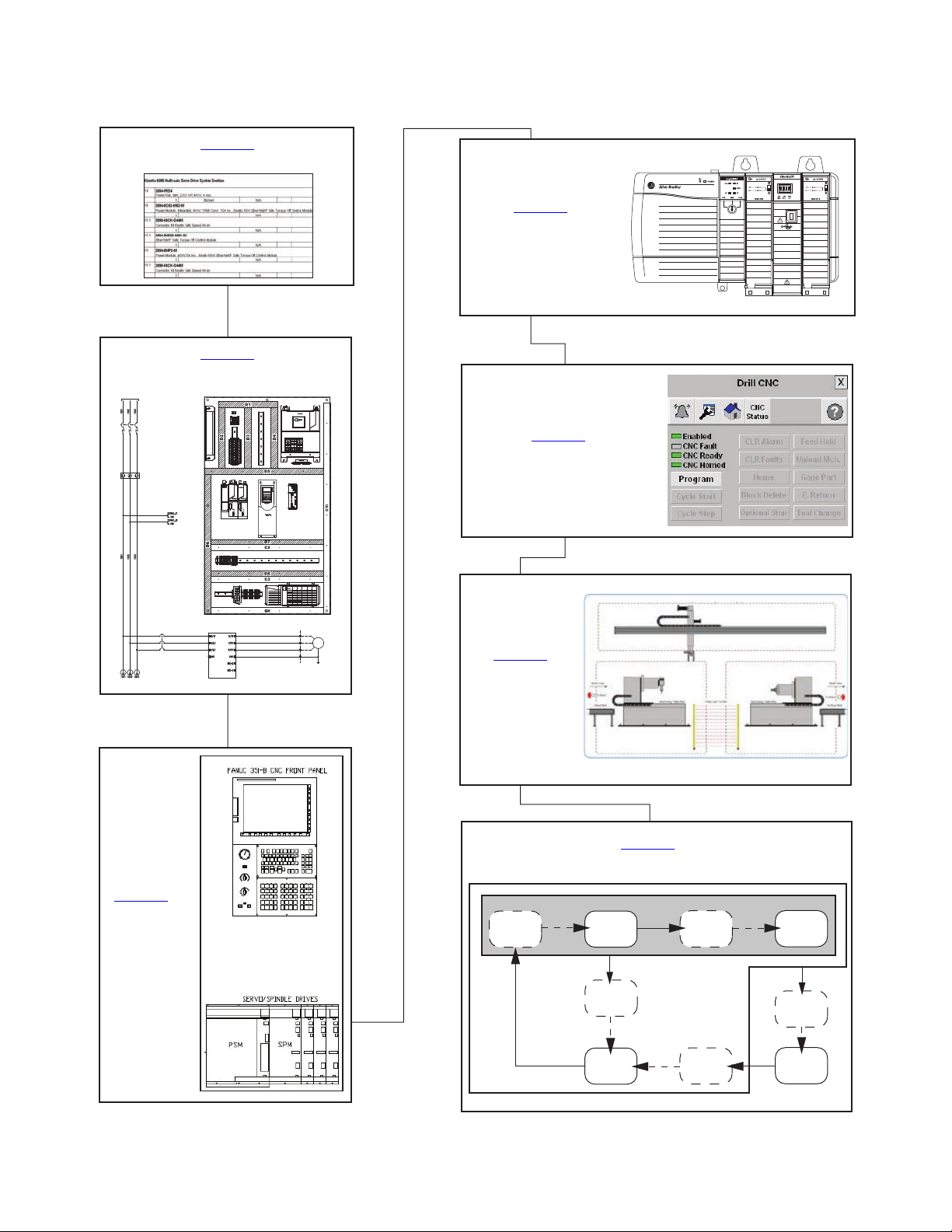
Follow this path to complete your CNC machining application.
MOTOR
FIELD SIDE
DRIVE
PROTECTION
POWERFLEX 4
AC DRIVE
MOTOR_01
USER PROTECTED
XXXVAC SUPPLY
MAINS DISCONNECT
PROTECTION
XXAMPS
FILTERED POWER
Chapter 7
Motion System Application Guide
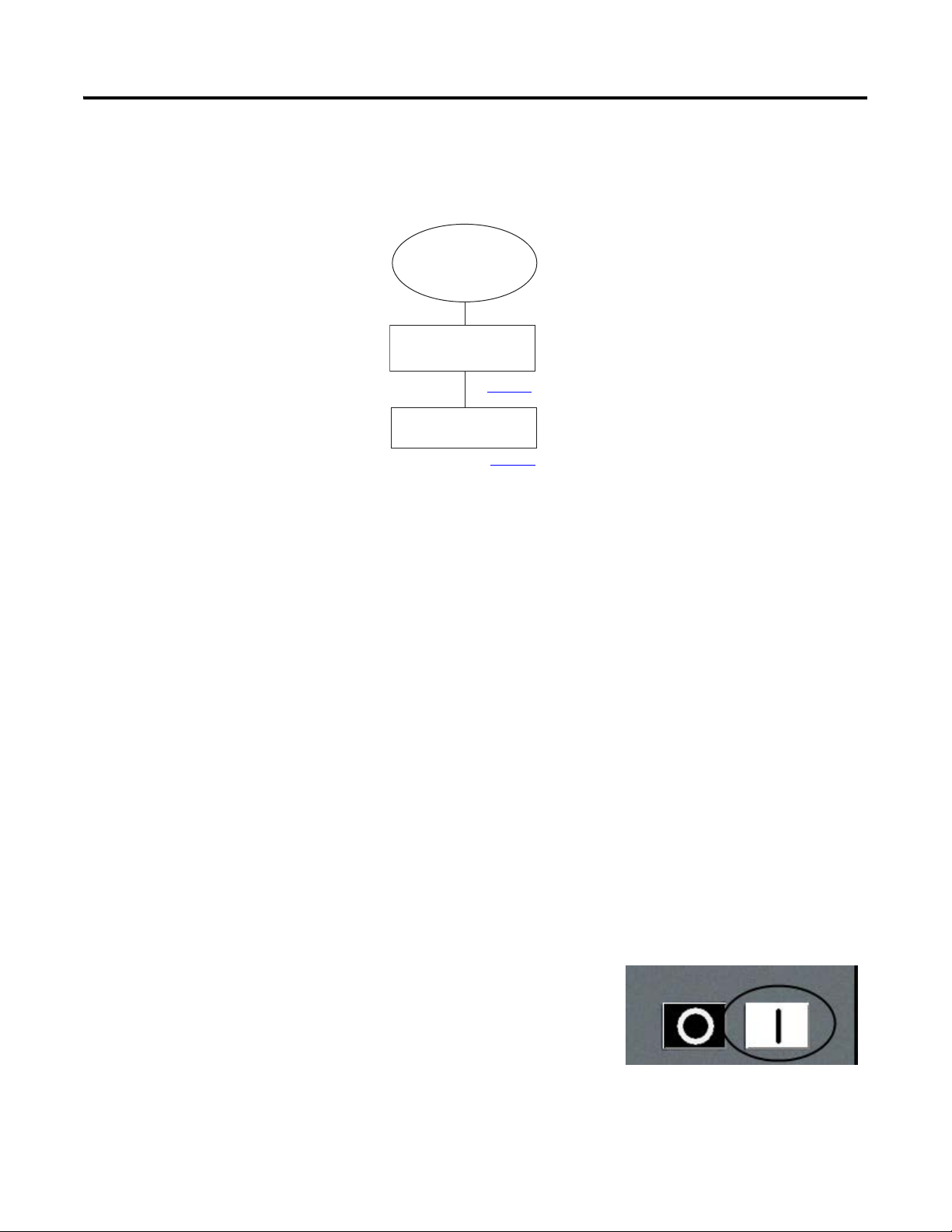
RESETTING
IDLE
(enabled)
STARTING
START
RUNNING
STOPPING
STOP
STOPPED
(disabled)
CLEARING
ABORTED
ABORTING
RESET
ABORT
CLEAR
The machine can go from any state in the shaded box to STOPPING.
The machine can go from any state
in the solid box to ABORTING.
Chapter 2
System Layout and Wiring
Chapter 1
Architecture and Hardware Selection
Chapter 3
FANUC CNC
Configuration
Chapter 4
GuardLogix®
Configuration
Chapter 7
System Application Guide
Chapter 5
FactoryTalk® View ME
Configuration
Chapter 6
System
Commissioning
Rockwell Automation Publication IASIMP-QS034A-EN-P - October 2012 3
Page 4

Where to Start
Notes:
4 Rockwell Automation Publication IASIMP-QS034A-EN-P - October 2012
Page 5

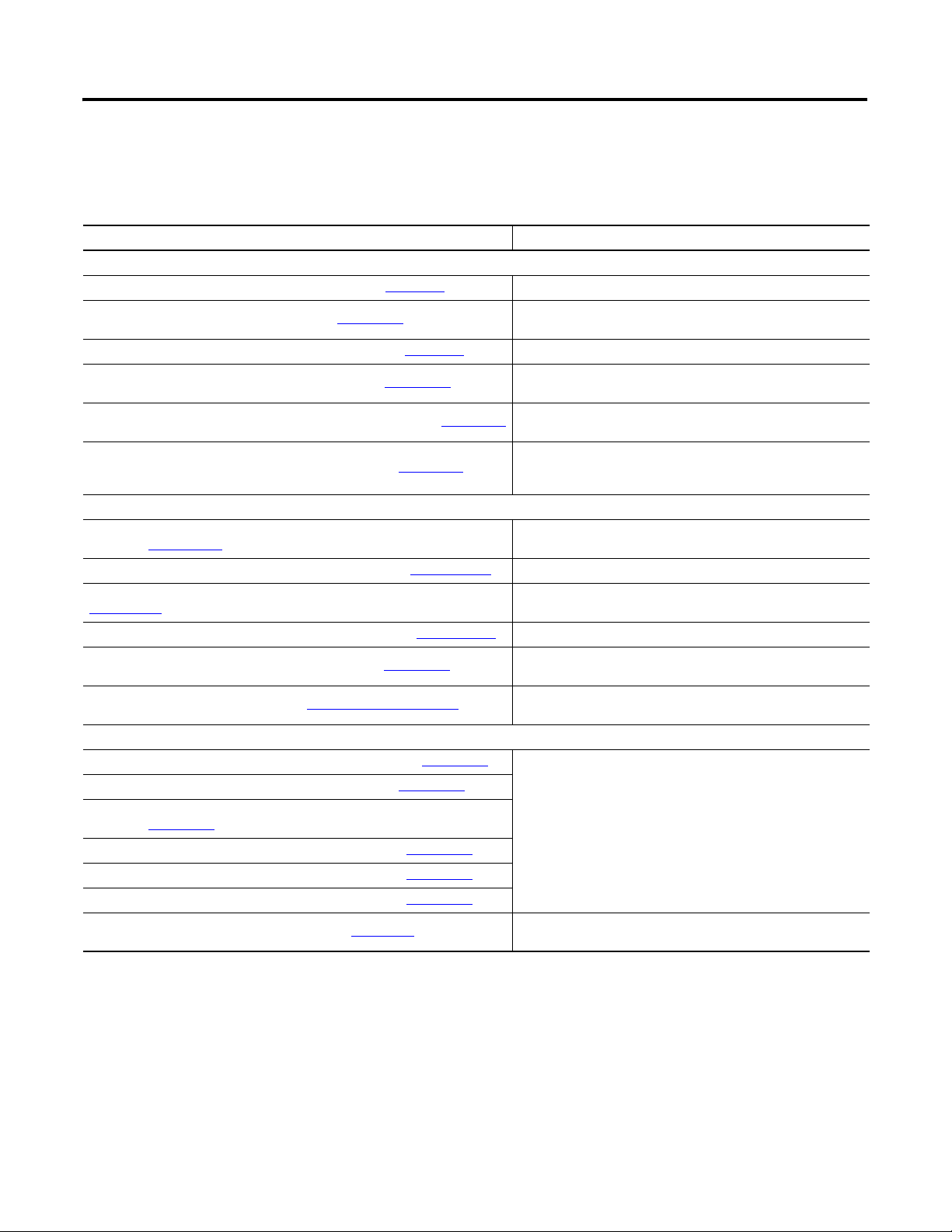
Table of Contents
Preface
Architecture and Hardware Selection
System Layout and Wiring
Introduction. . . . . . . . . . . . . . . . . . . . . . . . . . . . . . . . . . . . . . . . . . . . . . . . . . . . . 11
Conventions. . . . . . . . . . . . . . . . . . . . . . . . . . . . . . . . . . . . . . . . . . . . . . . . . . . . . 12
Required Software . . . . . . . . . . . . . . . . . . . . . . . . . . . . . . . . . . . . . . . . . . . . . . . 12
Additional Resources . . . . . . . . . . . . . . . . . . . . . . . . . . . . . . . . . . . . . . . . . . . . . 13
Additional Toolkits and FANUC Publications . . . . . . . . . . . . . . . . . 14
Chapter 1
Before You Begin . . . . . . . . . . . . . . . . . . . . . . . . . . . . . . . . . . . . . . . . . . . . . . . . 17
What You Need . . . . . . . . . . . . . . . . . . . . . . . . . . . . . . . . . . . . . . . . . . . . . . . . . 17
Follow These Steps. . . . . . . . . . . . . . . . . . . . . . . . . . . . . . . . . . . . . . . . . . . . . . . 18
Review System Selection and Configuration Tools . . . . . . . . . . . . . . . . . . 19
FANUC CNC Express Software . . . . . . . . . . . . . . . . . . . . . . . . . . . . . . 19
Rockwell Automation DMAT Wizard Software . . . . . . . . . . . . . . . . 19
Rockwell Automation Safety Selection Tools . . . . . . . . . . . . . . . . . . . 20
Rockwell Automation Product Selection Toolbox. . . . . . . . . . . . . . . 21
Open FANUC CNC Express Software . . . . . . . . . . . . . . . . . . . . . . . . . . . . 22
Create CNC System Bill of Materials . . . . . . . . . . . . . . . . . . . . . . . . . . . . . . 23
Create Supervisory Controller and Safety System Bill of Materials. . . . 28
Chapter 2
Before You Begin . . . . . . . . . . . . . . . . . . . . . . . . . . . . . . . . . . . . . . . . . . . . . . . . 30
What You Need . . . . . . . . . . . . . . . . . . . . . . . . . . . . . . . . . . . . . . . . . . . . . . . . . 30
Follow These Steps. . . . . . . . . . . . . . . . . . . . . . . . . . . . . . . . . . . . . . . . . . . . . . . 31
Select FANUC CNC Drawings from Drawing Library. . . . . . . . . . . . . . 31
Edit FANUC CNC Drawing Set. . . . . . . . . . . . . . . . . . . . . . . . . . . . . . . . . . 34
Create a New Project . . . . . . . . . . . . . . . . . . . . . . . . . . . . . . . . . . . . . . . . . 34
Edit CNC Power Drawings . . . . . . . . . . . . . . . . . . . . . . . . . . . . . . . . . . . 35
Edit CNC Safety and Standard I/O Drawings . . . . . . . . . . . . . . . . . . 38
Edit System Communication Drawings . . . . . . . . . . . . . . . . . . . . . . . . 41
Edit CNC System Layout Drawing . . . . . . . . . . . . . . . . . . . . . . . . . . . . 43
Assemble and Edit Your GuardLogix System Drawing Set . . . . . . . . . . . 44
FANUC CNC Configuration
Chapter 3
Before You Begin . . . . . . . . . . . . . . . . . . . . . . . . . . . . . . . . . . . . . . . . . . . . . . . . 47
What You Need . . . . . . . . . . . . . . . . . . . . . . . . . . . . . . . . . . . . . . . . . . . . . . . . . 47
Follow These Steps. . . . . . . . . . . . . . . . . . . . . . . . . . . . . . . . . . . . . . . . . . . . . . . 48
Initial FANUC CNC Configuration . . . . . . . . . . . . . . . . . . . . . . . . . . . . . . 48
System Powerup. . . . . . . . . . . . . . . . . . . . . . . . . . . . . . . . . . . . . . . . . . . . . . 48
Parameter Write Enable . . . . . . . . . . . . . . . . . . . . . . . . . . . . . . . . . . . . . . 49
High Speed Ethernet Option. . . . . . . . . . . . . . . . . . . . . . . . . . . . . . . . . . 51
Configure Ethernet Module . . . . . . . . . . . . . . . . . . . . . . . . . . . . . . . . . . . 53
Create a New Project File . . . . . . . . . . . . . . . . . . . . . . . . . . . . . . . . . . . . . 56
Download FANUC LADDER III Software Project
to the FANUC S35i-B CNC. . . . . . . . . . . . . . . . . . . . . . . . . . . . . . . . . . 60
Rockwell Automation Publication IASIMP-QS034A-EN-P - October 2012 5
Page 6

Table of Contents
USB External Device. . . . . . . . . . . . . . . . . . . . . . . . . . . . . . . . . . . . . . . . . . 63
EtherNet/IP Settings . . . . . . . . . . . . . . . . . . . . . . . . . . . . . . . . . . . . . . . . . 64
Logic Configuration . . . . . . . . . . . . . . . . . . . . . . . . . . . . . . . . . . . . . . . . . . . . . . 68
Editing Application Logic Modules and Adding Code . . . . . . . . . . . 70
Device Logic Modules. . . . . . . . . . . . . . . . . . . . . . . . . . . . . . . . . . . . . . . . . 73
Verify and Save the Project File . . . . . . . . . . . . . . . . . . . . . . . . . . . . . . . . 75
Download FANUC LADDER III Software Project
to the FANUC S35i-B CNC . . . . . . . . . . . . . . . . . . . . . . . . . . . . . . . . . . 77
Chapter 4
GuardLogix Configuration
Before You Begin. . . . . . . . . . . . . . . . . . . . . . . . . . . . . . . . . . . . . . . . . . . . . . . . . 82
What You Need. . . . . . . . . . . . . . . . . . . . . . . . . . . . . . . . . . . . . . . . . . . . . . . . . . 82
Follow These Steps . . . . . . . . . . . . . . . . . . . . . . . . . . . . . . . . . . . . . . . . . . . . . . . 83
Create an Initial GuardLogix Project Using the DMAT Wizard. . . . . . 84
Order and Run the DMAT Wizard . . . . . . . . . . . . . . . . . . . . . . . . . . . . 84
Import the Preconfigured RSLogix 5000 Project . . . . . . . . . . . . . . . . 84
GuardLogix Controller and Network Configuration . . . . . . . . . . . . . . . . 87
Create a New Project File. . . . . . . . . . . . . . . . . . . . . . . . . . . . . . . . . . . . . . 87
Configure Ethernet Module for your HMI Terminal
and CNC Modules . . . . . . . . . . . . . . . . . . . . . . . . . . . . . . . . . . . . . . . . . . . 89
Save the Project File. . . . . . . . . . . . . . . . . . . . . . . . . . . . . . . . . . . . . . . . . . . 90
Import and Configure the Machine Logic Module . . . . . . . . . . . . . . . . . . 91
FANUC CNC AOP Configuration . . . . . . . . . . . . . . . . . . . . . . . . . . . . . . . 95
Update FANUC CNC Add-On Profile (AOP) . . . . . . . . . . . . . . . . . 95
Add and Configure FANUC CNC . . . . . . . . . . . . . . . . . . . . . . . . . . . . 96
Save the Project File . . . . . . . . . . . . . . . . . . . . . . . . . . . . . . . . . . . . . . . . . . . . . . 99
Import and Configure CNC Application Logic Module . . . . . . . . . . . . 100
Import and Configure FANUC CNC Device Logic Modules . . . . . . . 104
Set String Tag Names for Alarm History Faceplate . . . . . . . . . . . . . . . . . 108
Set Visible Rows for Equipment Status Faceplate. . . . . . . . . . . . . . . . . . . 111
Import and Configure Device and Application Status Logic. . . . . . . . . 113
Create Specific Application Logic. . . . . . . . . . . . . . . . . . . . . . . . . . . . . . . . . 120
Application Code Logic Template Overview. . . . . . . . . . . . . . . . . . . 120
Application Logic Creation Steps That Use
Application Logic Examples . . . . . . . . . . . . . . . . . . . . . . . . . . . . . . . . . . 126
Application Logic Creation Steps That Use a Template. . . . . . . . . 136
Safety Logic Integration. . . . . . . . . . . . . . . . . . . . . . . . . . . . . . . . . . . . . . . . . . 137
Safety I/O. . . . . . . . . . . . . . . . . . . . . . . . . . . . . . . . . . . . . . . . . . . . . . . . . . . 137
GuardLogix Safety Logic . . . . . . . . . . . . . . . . . . . . . . . . . . . . . . . . . . . . . 138
Safety Faceplate Logic . . . . . . . . . . . . . . . . . . . . . . . . . . . . . . . . . . . . . . . . 144
Verify and Save the Project File . . . . . . . . . . . . . . . . . . . . . . . . . . . . . . . . . . . 146
Chapter 5
FactoryTalk View ME Configuration
6 Rockwell Automation Publication IASIMP-QS034A-EN-P - October 2012
Before You Begin. . . . . . . . . . . . . . . . . . . . . . . . . . . . . . . . . . . . . . . . . . . . . . . . 149
What You Need. . . . . . . . . . . . . . . . . . . . . . . . . . . . . . . . . . . . . . . . . . . . . . . . . 149
Follow These Steps . . . . . . . . . . . . . . . . . . . . . . . . . . . . . . . . . . . . . . . . . . . . . . 150
Page 7

Table of Contents
Design from a Preconfigured HMI Application File. . . . . . . . . . . . . . . . 151
Restore and Open a Preconfigured HMI Application. . . . . . . . . . . 151
Delete Unused Displays. . . . . . . . . . . . . . . . . . . . . . . . . . . . . . . . . . . . . . 154
Delete Unused Parameter Files . . . . . . . . . . . . . . . . . . . . . . . . . . . . . . . 155
Configure Parameter Files. . . . . . . . . . . . . . . . . . . . . . . . . . . . . . . . . . . . 156
Delete Unused Alarm Triggers and Tags . . . . . . . . . . . . . . . . . . . . . . 160
Design from an Existing HMI Application File . . . . . . . . . . . . . . . . . . . . 162
Open Your Existing HMI Application File and Add Displays . . . 162
Add Parameter Files . . . . . . . . . . . . . . . . . . . . . . . . . . . . . . . . . . . . . . . . . 165
Configure Parameter Files. . . . . . . . . . . . . . . . . . . . . . . . . . . . . . . . . . . . 167
Import Alarm Setup File . . . . . . . . . . . . . . . . . . . . . . . . . . . . . . . . . . . . . 171
Delete Unused Alarm Triggers . . . . . . . . . . . . . . . . . . . . . . . . . . . . . . 173
Import and Edit Alarm Tags . . . . . . . . . . . . . . . . . . . . . . . . . . . . . . . . . 174
Configure Goto Display Buttons on Startup Display . . . . . . . . . . . . . . . 177
Add FANUC CNC Goto Buttons to Your Application . . . . . . . . 177
Associate Each Button to a Faceplate and Parameter File. . . . . . . . 179
Configure Equipment Status Faceplate Display . . . . . . . . . . . . . . . . . . . . 185
Add the Equipment Status Faceplate Display . . . . . . . . . . . . . . . . . . 186
Add the ME_Equipment_Parameter File. . . . . . . . . . . . . . . . . . . . . . 187
Configure Goto Buttons on the Equipment Status Faceplate . . . . 189
Configure Additional Device Value Columns. . . . . . . . . . . . . . . . . . 191
Configure Safety Faceplate Displays . . . . . . . . . . . . . . . . . . . . . . . . . . . . . . 193
System Commissioning
Chapter 6
Before You Begin . . . . . . . . . . . . . . . . . . . . . . . . . . . . . . . . . . . . . . . . . . . . . . . 195
What You Need . . . . . . . . . . . . . . . . . . . . . . . . . . . . . . . . . . . . . . . . . . . . . . . . 195
Follow These Steps. . . . . . . . . . . . . . . . . . . . . . . . . . . . . . . . . . . . . . . . . . . . . . 196
Download Applications . . . . . . . . . . . . . . . . . . . . . . . . . . . . . . . . . . . . . . . . . 197
Download RSLogix 5000 Software Project File
to the Logix Controller . . . . . . . . . . . . . . . . . . . . . . . . . . . . . . . . . . . . . . 197
Configure and Download FactoryTalk Project
to PanelView Plus Terminal . . . . . . . . . . . . . . . . . . . . . . . . . . . . . . . . . . 198
Commissioning Devices . . . . . . . . . . . . . . . . . . . . . . . . . . . . . . . . . . . . . . . . . 205
Commissioning CIP Motion Drives . . . . . . . . . . . . . . . . . . . . . . . . . . 205
Commissioning sercos Drives . . . . . . . . . . . . . . . . . . . . . . . . . . . . . . . . 205
Commissioning PowerFlex 7-class Drives. . . . . . . . . . . . . . . . . . . . . . 205
Commissioning PowerFlex 4-class Drives. . . . . . . . . . . . . . . . . . . . . . 205
Commissioning Kinetix 300 Drives . . . . . . . . . . . . . . . . . . . . . . . . . . . 205
Commissioning Supervisory and CNC System . . . . . . . . . . . . . . . . . . . . 206
Verify Network Communication . . . . . . . . . . . . . . . . . . . . . . . . . . . . . 206
Clearing Faults . . . . . . . . . . . . . . . . . . . . . . . . . . . . . . . . . . . . . . . . . . . . . . 212
Operator (manual) Control . . . . . . . . . . . . . . . . . . . . . . . . . . . . . . . . . . 212
Program (automatic) Control . . . . . . . . . . . . . . . . . . . . . . . . . . . . . . . . 213
Rockwell Automation Publication IASIMP-QS034A-EN-P - October 2012 7
Page 8

Table of Contents
Chapter 7
System Application Guide
Before You Begin. . . . . . . . . . . . . . . . . . . . . . . . . . . . . . . . . . . . . . . . . . . . . . . . 215
What You Need. . . . . . . . . . . . . . . . . . . . . . . . . . . . . . . . . . . . . . . . . . . . . . . . . 215
Follow These Steps . . . . . . . . . . . . . . . . . . . . . . . . . . . . . . . . . . . . . . . . . . . . . . 216
Machine Startup Faceplate . . . . . . . . . . . . . . . . . . . . . . . . . . . . . . . . . . . . . . . 217
Machine Status . . . . . . . . . . . . . . . . . . . . . . . . . . . . . . . . . . . . . . . . . . . . . . 217
Machine Control . . . . . . . . . . . . . . . . . . . . . . . . . . . . . . . . . . . . . . . . . . . . 219
Program/Operator Mode . . . . . . . . . . . . . . . . . . . . . . . . . . . . . . . . . . . . 219
State Diagram Faceplate Display . . . . . . . . . . . . . . . . . . . . . . . . . . . . . . 220
CNC Faceplate . . . . . . . . . . . . . . . . . . . . . . . . . . . . . . . . . . . . . . . . . . . . . . . . . 221
Home View . . . . . . . . . . . . . . . . . . . . . . . . . . . . . . . . . . . . . . . . . . . . . . . . . 221
CNC Status Views. . . . . . . . . . . . . . . . . . . . . . . . . . . . . . . . . . . . . . . . . . . 222
CNC Control Views. . . . . . . . . . . . . . . . . . . . . . . . . . . . . . . . . . . . . . . . . 222
Fault Indication View . . . . . . . . . . . . . . . . . . . . . . . . . . . . . . . . . . . . . . . . 223
Fault Diagnostic Views. . . . . . . . . . . . . . . . . . . . . . . . . . . . . . . . . . . . . . . 224
Configuration View. . . . . . . . . . . . . . . . . . . . . . . . . . . . . . . . . . . . . . . . . . 225
Online Help Views . . . . . . . . . . . . . . . . . . . . . . . . . . . . . . . . . . . . . . . . . . 226
Motion Drive and/or PowerFlex Drive Faceplates. . . . . . . . . . . . . . . . . . 226
Guard I/O Safety Faceplates. . . . . . . . . . . . . . . . . . . . . . . . . . . . . . . . . . . . . . 226
Equipment Status Display Overview . . . . . . . . . . . . . . . . . . . . . . . . . . . . . . 226
Alarm History Display Overview . . . . . . . . . . . . . . . . . . . . . . . . . . . . . . . . . 228
Logic Program Overview
Logic Module Customization
Add Other Devices to the Equipment
Status Faceplate
Appendix A
Machine/Application/Device Module Relationship . . . . . . . . . . . . . . . . 230
Module Routine Overview . . . . . . . . . . . . . . . . . . . . . . . . . . . . . . . . . . . . . . . 231
Machine Module . . . . . . . . . . . . . . . . . . . . . . . . . . . . . . . . . . . . . . . . . . . . 234
Application Modules. . . . . . . . . . . . . . . . . . . . . . . . . . . . . . . . . . . . . . . . . 240
Device Modules . . . . . . . . . . . . . . . . . . . . . . . . . . . . . . . . . . . . . . . . . . . . . 241
Appendix B
Machine State Customization . . . . . . . . . . . . . . . . . . . . . . . . . . . . . . . . . . . . 243
Tag and Logic Modification Recommendations . . . . . . . . . . . . . . . . 246
State Display Tag Modifications . . . . . . . . . . . . . . . . . . . . . . . . . . . . . . 247
Bypass Idle State Modifications . . . . . . . . . . . . . . . . . . . . . . . . . . . . . . . 248
Module Fault Customization. . . . . . . . . . . . . . . . . . . . . . . . . . . . . . . . . . . . . 249
Alarm History Faceplate Logic Modification . . . . . . . . . . . . . . . . . . . . . . 252
Coordinated Reset Customization . . . . . . . . . . . . . . . . . . . . . . . . . . . . . . . . 253
Appendix C
Add Devices to the Equipment Status Faceplate. . . . . . . . . . . . . . . . . . . . 255
Add Optional Faceplate Views . . . . . . . . . . . . . . . . . . . . . . . . . . . . . . . . . . . 258
8 Rockwell Automation Publication IASIMP-QS034A-EN-P - October 2012
Page 9

Appendix D
Table of Contents
Logix Communication and Controller
Configuration
Index
Configure Personal Computer Communication Properties . . . . . . . . . 261
Configure the EtherNet/IP Driver . . . . . . . . . . . . . . . . . . . . . . . . . . . . . . . 263
Configure the Logix Controller . . . . . . . . . . . . . . . . . . . . . . . . . . . . . . . . . . 264
Rockwell Automation Publication IASIMP-QS034A-EN-P - October 2012 9
Page 10

Table of Contents
Notes:
10 Rockwell Automation Publication IASIMP-QS034A-EN-P - October 2012
Page 11

Preface
IMPORTANT
Introduction
This quick start provides step by step instructions for using the CNC
Machining Accelerator Toolkit to help you design, install, operate, and
maintain a CNC work cell incorporating a GuardLogix Supervisory
Controller and FANUC Series 30i-B, 31i-B, 32i-B, or 35i-B CNC System.
Included are selection tools, layout and wiring drawings, and
pre-configured logic and HMI files to assist you in creating an Integrated
Architecture™ solution for your application requirements.
All the supporting files are included on the CNC Machining Accelerator
Toolkit DVD, publication IASIMP-SP018. The DVD provides PLC and
CNC selection tools; CAD drawings for panel layout and wiring; basic
status, control, and diagnostic logic files; FactoryTalk View ME faceplates,
and more. For a copy of the DVD, contact your local Rockwell
Automation distributor or sales representative. With these tools and the
built-in best-practices design, the system designer is free to focus on the
design of their machine control and not on design overhead tasks.
You can also download these same supporting files from the
Rockwell Automation® Integrated Architecture Tools website,
http://www.ab.com/go/iatools on the Beyond Getting Started tab.
Before using this quick start and the contents of the CNC Machining
Accelerator Toolkit DVD, read the Terms and Conditions READ ME PDF
file on the DVD.
The beginning of each chapter contains the following information. Read
these sections carefully before beginning work in each chapter:
• Before You Begin - This section lists the steps that must be
completed and decisions that must be made before starting that
chapter. The chapters in this quick start do not have to be completed
in the order in which they appear, but this section defines the
minimum amount of preparation required before completing the
current chapter.
• What You Need - This section lists the tools that are required to
complete the steps in the current chapter. This includes, but is not
limited to, hardware and software.
• Follow These Steps - This illustrates the steps in the current chapter
and identifies which steps are required to complete the examples by
using specific networks.
Rockwell Automation Publication IASIMP-QS034A-EN-P - October 2012 11
Page 12

Preface
Conventions
Convention Meaning Example
CNC
Click
Double-click
Right-click
Drag and drop
Select Click to highlight a menu item or list choice. From the pull-down menu, choose H1-1.
Check/uncheck Click to select a checkbox option.
>
Expand Click the + to the left of a given item /folder to show its contents. In the H1-1 dialog box, expand FFLD.
Enter Used when you can type from the keyboard or choose from a list. Enter the catalog number of the product.
Type Used when the only option is to type from the keyboard. Type the catalog number of the product.
Press
Used as an abbreviation for Computer Numeric Control. In this Toolkit,
The GuardLogix PLC communicates to the FANUC CNC by using the
EtherNet/IP communication protocol.
Click the left mouse button once (assumes cursor is positioned on object
or selection). Click button to initiate action.
Click the left mouse button twice in quick succession (assumes cursor is
positioned on object or selection).
Click the right mouse button once (assumes cursor is positioned on
object or selection).
Click and hold the left mouse button on an object, move the cursor to
where you want to move the object, and release the mouse button.
Shows nested menu selections as menu name followed by menu
selection.
Press a specific button on the PanelView™ terminal or other component
with touch-screen technology.
This manual uses the following conventions.
GuardLogix PLC to FANUC CNC EtherNet/IP
configuration.
Click Browse.
Double-click the H1 icon.
Right-click the Fieldbus Networks icon.
Drag and drop the desired block into the Strategy
dialog box.
Check Consider Case if you want to conduct a
case-sensitive search.
Click File>Page Setup>Options.
Press Axis Control.
Required Software
Rockwell Automation Software Cat. No. Version Required For
RSLogix™ 5000
• ControlFLASH™
• BOOTP/DHCP utility (EtherNet/IP network)
• RSLinx® Classic
FactoryTalk View Studio for Machine Edition
• FactoryTalk Services
• RSLinx Enterprise
• RSLinx Classic
FANUC III for PMC Development
(Microsoft Windows)
CNC Machining Accelerator Toolkit DVD IASIMP-SP018
To complete this quick start, the following software is required.
9324-RLD300RNE 20.00 or later
9701-VWSTMENE 6.00 or later PanelView Plus terminals
A08B-9210-J505 6.80 or later FANUC CNC applications
N/A
All ControlLogix®/GuardLogix PLC
applications
CAD files, wiring diagrams,
application files, and other
support information
12 Rockwell Automation Publication IASIMP-QS034A-EN-P - October 2012
Page 13
Preface
Additional Resources
These documents contain additional information concerning related
products from Rockwell Automation.
Table 1 - Additional Resources
Resource Description
Guard Logix and Compact Logix Controllers
GuardLogix Controller Installation Instructions, publication 1756-IN045 Provides information on installing the GuardLogix controller
GuardLogix Controllers User Manual, publication 1756-UM020
CompactLogix Controllers Installation Instructions, publication 1768-IN004 Provides information on installing the CompactLogix™ controller
Compact GuardLogix Controllers User Manual, publication 1768-UM002
GuardLogix Controller Systems Safety Reference Manual, publication 1756-RM093
Logix Common Procedures Programming Manual, publication 1756-PM001
Safety Modules and Products
CompactBlock Guard I/O DeviceNet Safety Module Installation Instructions,
publication 1791DS-IN002
Guard I/O DeviceNet Safety Modules User Manual, publication 1791DS-UM001 Provides information on using Guard I/O DeviceNet Safety modules
Guard I/O EtherNet/IP Safety Modules Installation Instructions, publication
1791ES-IN001
Guard I/O EtherNet/IP Safety Modules User Manual, publication 1791ES-UM001
POINT Guard I/O Safety Module User Manual, publication 1734-UM013
Safety Products Catalog S116, available at http://www.ab.com/catalogs/
Kinetix Drives
Kinetix 300 EtherNet/IP Indexing Drives User Manual, publication 2097-UM001
Kinetix 350 Single-axis EtherNet/IP Servo Drives, publication 2097-UM002
Kinetix 6200 and Kinetix 6500 Modular Multi-axis Servo Drives User Manual,
publication 2094-UM002
Kinetix 6000 Multi-axis Servo Drives User Manual, publication 2094-UM001
Kinetix 2000 Multi-axis Servo Drives User Manual, publication 2093-UM001
Kinetix 7000 Multi-axis Servo Drives User Manual, publication 2099-UM001
Kinetix Motion Control Selection Guide, publication GMC-SG001
Provides information on configuring and programming the 1756
GuardLogix system
Provides information on configuring and programming the 1768
Compact GuardLogix system
Contains detailed requirements for achieving and maintaining SIL 3
with the GuardLogix controller system
Provides information on programming Logix5000 controllers,
including managing project files, organizing tags, programming and
testing routines, and handling faults
Provides information on installing CompactBlock™ Guard I/O™
DeviceNet Safety modules
Provides information on installing CompactBlock Guard I/O
EtherNet/IP Safety modules
Provides information on using Guard I/O EtherNet/IP Safety modules
Provides information on installing, configuring and operating POINT
Guard I/O Safety Modules
Provides selection and specification information for Rockwell
Automation safety products.
Provides mounting, wiring, configuring, and troubleshooting
instructions for the Kinetix® Motion Control servo drives
Provides drive specifications, motor/servo-drive system
combinations, and accessories for Kinetix motion control products
Rockwell Automation Publication IASIMP-QS034A-EN-P - October 2012 13
Page 14
Preface
Table 1 - Additional Resources (Continued)
Resource Description
CIP Motion and sercos
SERCOS and Analog Motion Configuration and Startup User Manual,
publication MOTION-UM001
CIP Motion Reference Manual, publication MOTION-RM003
CIP Motion Configuration and Startup User Manual, publication MOTION-UM003
Online Configuration and Selection Tools
Rockwell Automation Configuration and Selection Tools, available at
http://www.rockwellautomation.com/en/e-tools/
Information on configuring and troubleshooting your ControlLogix
and CompactLogix sercos interface modules
Provides descriptions of the AXIS_CIP_DRIVE attributes and
RSLogix 5000 software Control Modes and Methods
Information on configuring and troubleshooting your ControlLogix
and CompactLogix EtherNet/IP network modules
These online tools install on your personal computer so that you can
quickly access information on our products:
• CrossWorks™
• Industrial Computer Selector
• Operator Interface Selection Tool
• Programmable Controller Family Selector
You can view or download publications at
http://www.rockwellautomation.com/literature. To order paper copies of
technical documentation, contact your local Allen-Bradley distributor or
Rockwell Automation sales representative.
Additional Toolkits and FANUC Publications
This table provides information for supporting toolkits and FANUC
publications.
Toolkits and FANUC Publications Description
Drives and Motion Accelerator Toolkit DVD, publication IASIMP-SP017 Toolkit for sercos interface or EtherNet/IP-based motion control
Safety Accelerator Toolkit DVD, publication SAFETY-CL002
FANUC Series 30i/31i/32i/35i -MODEL B, EtherNet/IP Adapter function,
publication B-64014EN/04-2
FANUC Series 30i/31i/32i/35i -MODEL B, FANUC Power Motion i -MODEL A,
EtherNet/IP Scanner function, publication B-64014EN/04-3
You can request the FANUC publications by contacting your local
FANUC America distributor or sales representative.
http://www.FANUCfa.com/us-en/Home
Toolkit to provide a framework for developing safety applications.
Information on configuring and troubleshooting your FANUC CNC's
EtherNet/IP network modules.
Information on configuring and troubleshooting your FANUC CNC's
EtherNet/IP network modules.
14 Rockwell Automation Publication IASIMP-QS034A-EN-P - October 2012
Page 15

Chapter
1
Architecture and Hardware Selection
In this chapter you are introduced to the FANUC CNC Express software to create an EtherNet/IP bill of
materials for your CNC system. The CNC Express software provides the means to select hardware and software
from FANUC that are stocked locally in the United States. This is for reference only, and is not to be used for
final product selection. Please contact your local FANUC representative prior to purchase.
Use either the Drives and Motion Accelerator Toolkit DVD, publication IASIMP-SP017, and/or Safety
Accelerator Toolkit DVD, publication SAFETY-CL002, to configure the Rockwell Automation system, or to
select the power distribution components for the CNC control system. Be sure that an 1756-EN2TR or
1756-EN3TR Ethernet module is selected for the Rockwell Automation system.
To assist you with a possible architecture and hardware selection, reference the CNC Work Cell machine
application. The CNC Work Cell machine application is an example only, with the focus of the toolkit being the
integration between the Rockwell Automation GuardLogix controller and the FANUC CNC.
See Figure 1 on page 16 for a CNC work cell application example.
Rockwell Automation Publication IASIMP-QS034A-EN-P - October 2012 15
Page 16
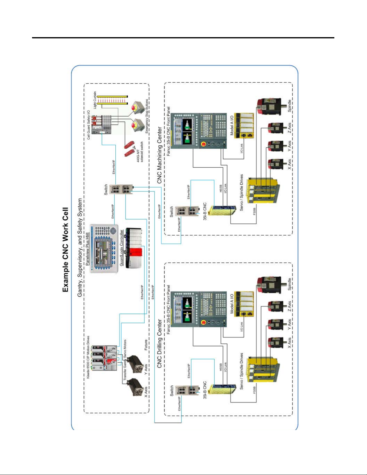
Chapter 1 Architecture and Hardware Selection
Figure 1 - CNC Work Cell Application Example
16 Rockwell Automation Publication IASIMP-QS034A-EN-P - October 2012
Page 17

Architecture and Hardware Selection Chapter 1
Before You Begin
Collect specific application data, for example:
• System input voltage
• System CNC model and display options
• CNC required options
• System I/O requirements
• Motor and drive sizing
• Other system sizing info
What You Need
• The CNC Machining Accelerator Toolkit DVD, publication IASIMP-SP018. For a copy of the DVD,
contact your local Rockwell Automation distributor or sales representative.
• FANUC CNC Express selection software. For a copy of the DVD, contact your local FANUC sales
representative.
• If Rockwell Automation Kinetix or PowerFlex® Drives are used in the system, the Drives and Motion
Accelerator Toolkit DVD is required, publication IASIMP-SP017. For a copy of the DVD, contact your
local Rockwell Automation distributor or sales representative.
• If Rockwell Automation GuardLogix safety controller and safety components are used in the system, the
Safety Accelerator Toolkit DVD is required, publication SAFETY-CL002. For a copy of the DVD,
contact your local Rockwell Automation distributor or sales representative.
Rockwell Automation Publication IASIMP-QS034A-EN-P - October 2012 17
Page 18

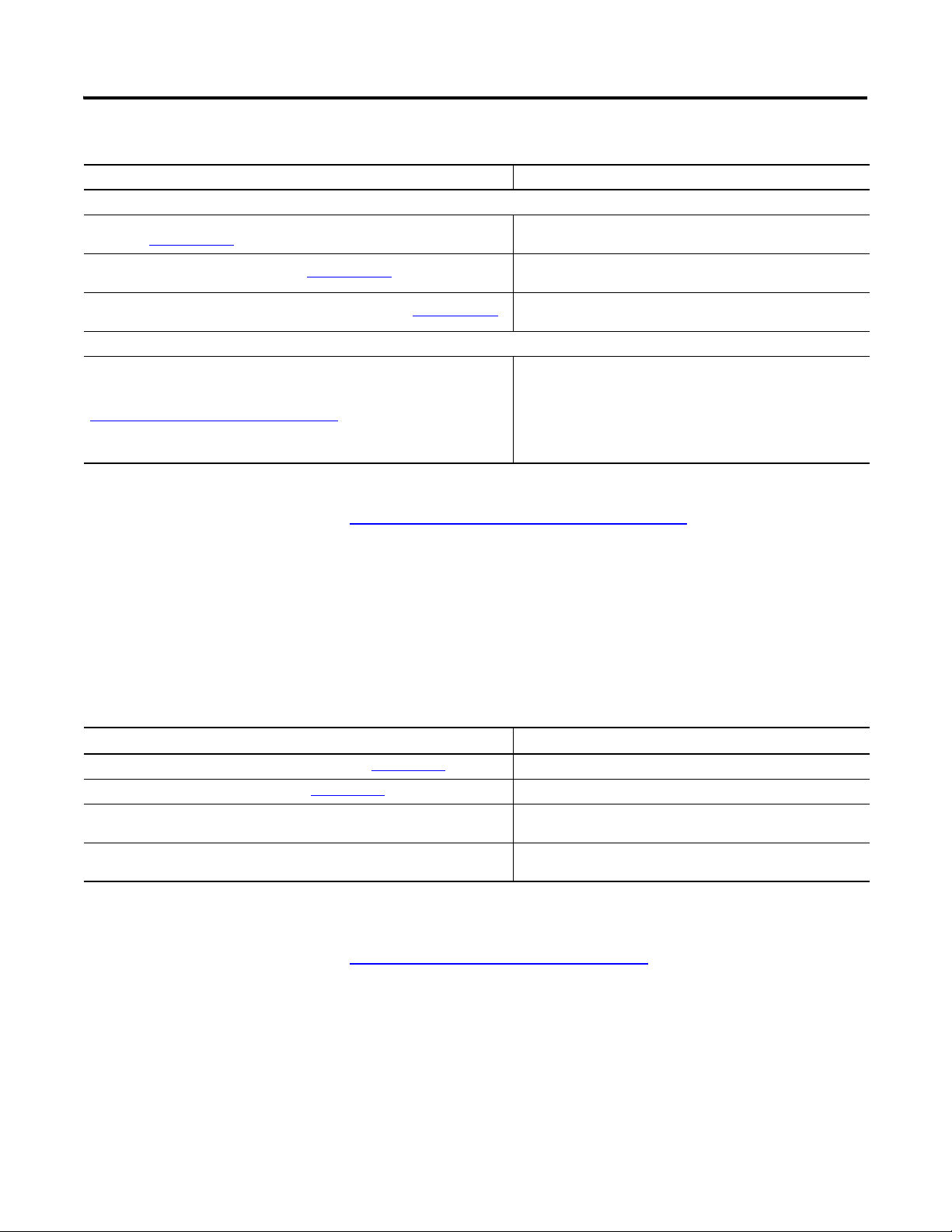
Chapter 1 Architecture and Hardware Selection
Open FANUC CNC
Express Software
page 22
Create CNC System Bill
of Materials
page 23
Review System Selection
and Configuration Tools
page 19
page 28
Create Supervisory
Controller and Safety
System Bill of Materials
Follow These Steps
Complete the following steps to create a bill of materials for your CNC system.
Start
18 Rockwell Automation Publication IASIMP-QS034A-EN-P - October 2012
Page 19
Architecture and Hardware Selection Chapter 1
Review System Selection and Configuration Tools
This section provides and overview of the FANUC and Rockwell Automation system selection and
configuration tools that you may need for your FANUC configuration.
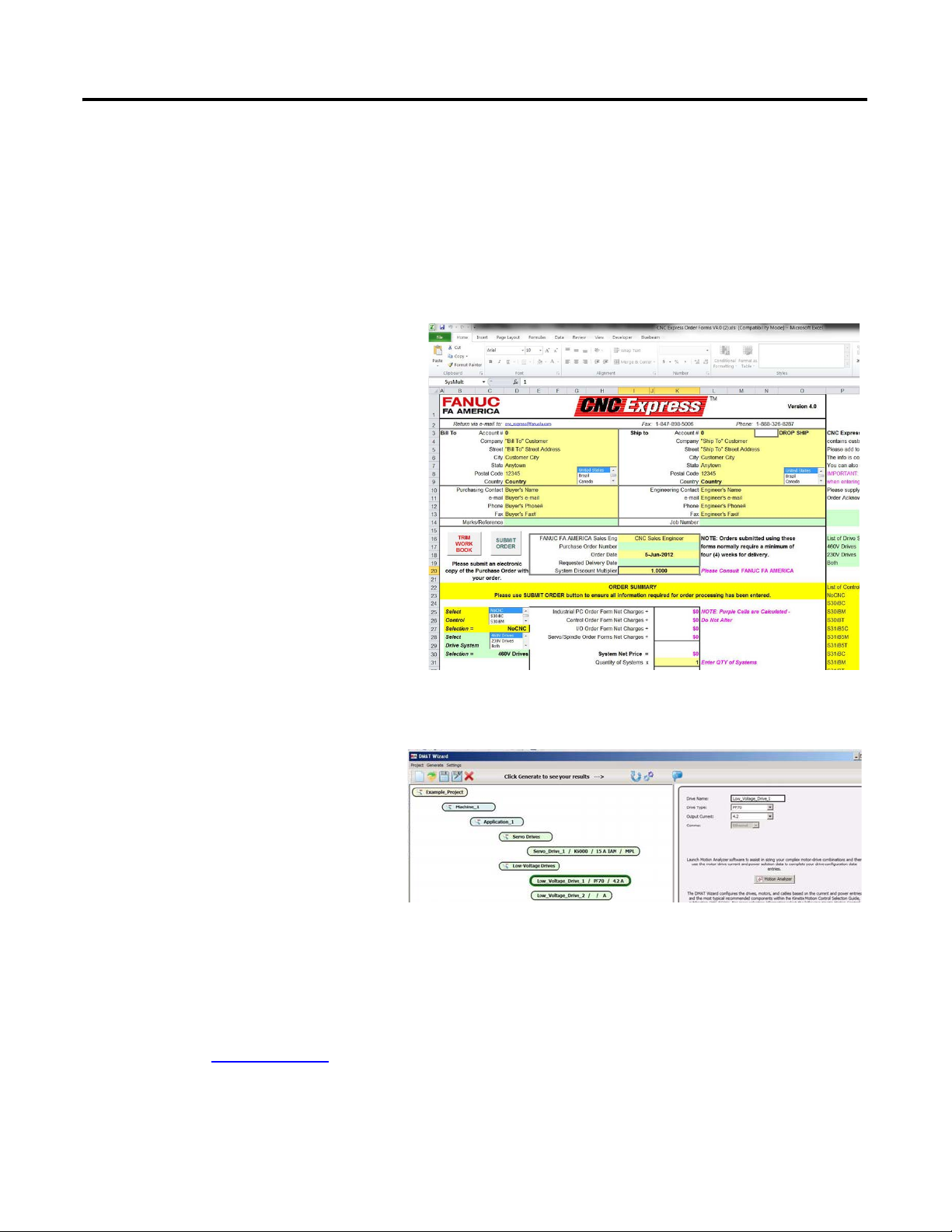
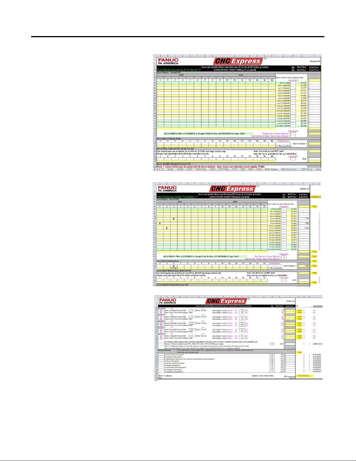
FANUC CNC Express Software
The Excel workbook CNC Express Order
Forms.xls contains the product information
and the actual order forms. Each worksheet
represents a certain product and contains the
relevant order guide information for the
product selections offered in that worksheet,
and is followed by the order form. To order
from this workbook, you make simple product
selections by using check marks, and the
workbook does the rest of the work.
Rockwell Automation DMAT Wizard Software
The Drives and Motion Accelerator Toolkit
(DMAT) Wizard software provides a
streamlined way of creating a bill of
material, assembling a system drawing set,
and creating a RSLogix 5000 project file
with a preconfigured controller, network,
drives, and initial system program logic.
This can be accomplished in minutes by
inserting simple system and drive
configuration entries, and running other
system selection tools as needed.
You can access this software tool on the
Drives and Motion Accelerator Toolkit
DVD, publication IASIMP-SP017.
Rockwell Automation Publication IASIMP-QS034A-EN-P - October 2012 19
Page 20

Chapter 1 Architecture and Hardware Selection
Rockwell Automation Safety Selection Tools
The Safety Accelerator Toolkit provides a
number of software selection tools to assist
in hardware selection and performance
estimation for your safety systems. You may
access these software tools within the
Safety Accelerator Toolkit DVD,
publication SAFETY-CL002.
20 Rockwell Automation Publication IASIMP-QS034A-EN-P - October 2012
Page 21
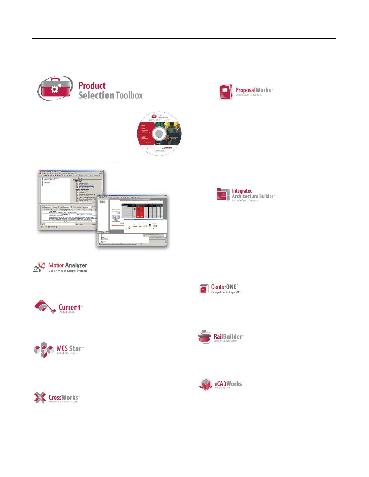
Rockwell Automation Product Selection Toolbox
The Rockwell Automation Product Selection Toolbox
(PST) offers a complete suite of user tools for product
selection and configuration across produc t lines from
project conception through final design. From push
buttons to drives to motor control centers and fully
networked control systems, you’ll find the product
information and configuration assistance you need to
help you and your customers succeed with Rockwell
Automation.
• Provides access to information on a broad range of
Allen-Bradley® products and services
• Easy product selection inter face to make it a snap to
determine the exact catalog numbers for the item
you need
• Access to current list pricing, and a comprehensive
supplemental product information list
• Contains features, such as product selection wizards,
agreement pricing, a spare parts generator, and the
ability to separate par t numbers to see what
Rockwell Automation components comprise them
• All of these features and more can help you select
the correct product based on your requirements and
give your customers the information they need fast
• Lets you quickly develop Logix/NetLinx control
system configurations with BOM and reports
• Integration with configurator allows configuration
of PowerFlex drives and ArmorStart motor
controllers
• Motion control drive/motor combinations and
accessories can be added through links to Motion
Analyzer software
• New Ethernet capabilities include Stratix™ switches
and physical media with enhanced graphical views
• IAB output can be easily exported to ProposalWorks
to take advantage of extended proposal generation
features, and supplementary data
Product Selection & System Design Tools
• Assists the user in selecting correct motor for application, proper drive, and gearbox
(if required)
• Effective optimization capabilities allow user to get the most out of the selected
motor and drive combination
• Allows users to have the most up-to-date applications, product, price, and
supplementary information
• All programs are scheduled for update every three weeks
• Assists in crossing competitive part numbers to Rockwell Automation equivalents
• Gives users the ability to submit crosses directly to PST and they will provide a cross or users
can go to: ab.com/e-tools
and look up existing cross references in the database
• Allows you select product 3D CAD drawings in AutoCAD software
• Provides you with access to thousands of drawings for a wide range of Allen-Bradley
products as well as assistance configuring catalog numbers
• Helps you configure Motor Control Syste m starters for rated motor voltages from 230… 690V
• Program provides the correct catalog number, wiring diagram, and layout drawing for starters
of your choice
• Provides assistance in selecting and dimensioning all of required busbar rack components
• Simplifies the design of custom terminal block rails
• Allows you to select and place terminal blocks on mounting rail along with
specifying labeling of terminal blocks, locating jumper bars between blocks,
automatically selecting end barriers, and partition plates
• Intuitive software application designed specifically for configuring Motor
Control Centers
• User friendly interface helps reduce error and enables customers to get their
MCCs quickly
Architecture and Hardware Selection Chapter 1
Rockwell Automation Publication IASIMP-QS034A-EN-P - October 2012 21
Page 22
Chapter 1 Architecture and Hardware Selection
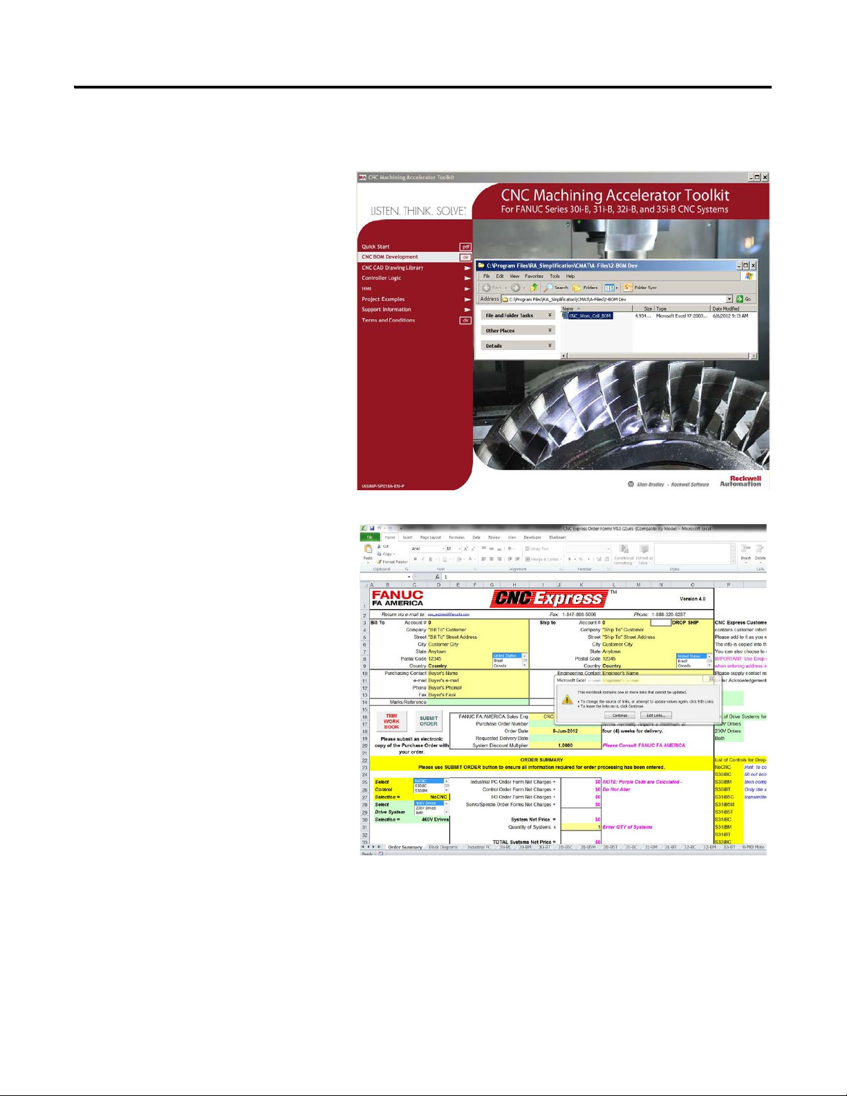
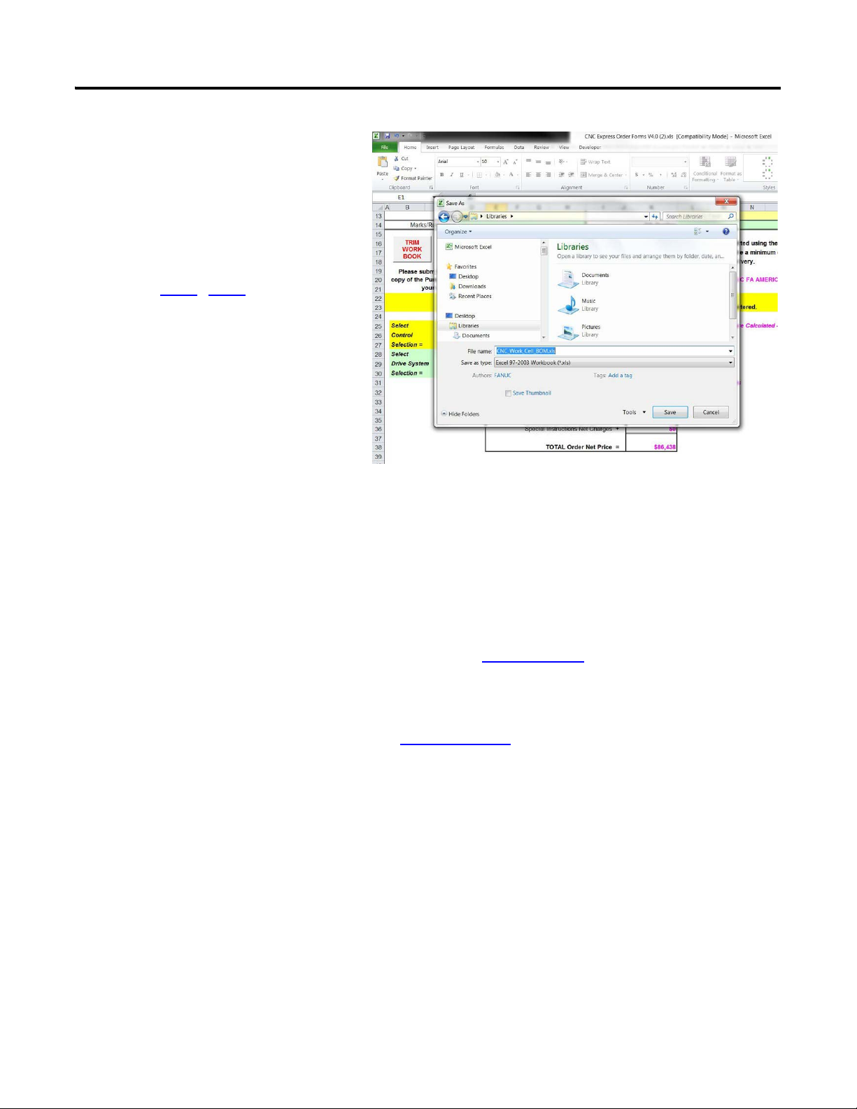
Open FANUC CNC Express Software
1. Navigate to and choose the CNC
Express application,
CNC_Work_Cell_BOM.xlsx,
on the CNC Machining Accelerator
Toolkit DVD.
The initial CNC Express dialog box
opens.
22 Rockwell Automation Publication IASIMP-QS034A-EN-P - October 2012
Page 23
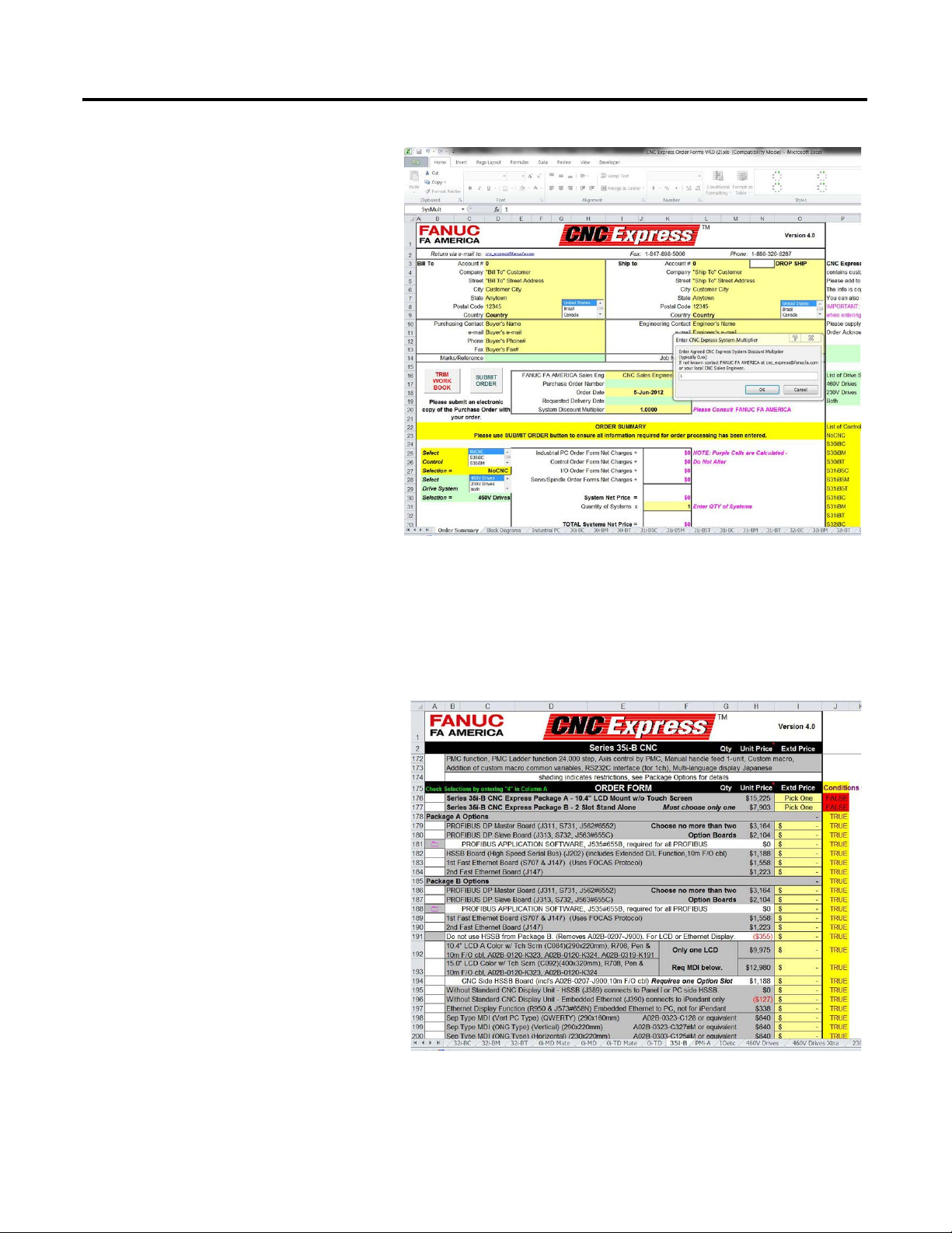
2. Click continue to leave the links as
they are. The multiplier pop up
window will then be displayed.
3. Add the multiplier that has been
approved by FANUC, and then click
OK. You are now ready to begin
creating the bill of materials (BOM).
Architecture and Hardware Selection Chapter 1
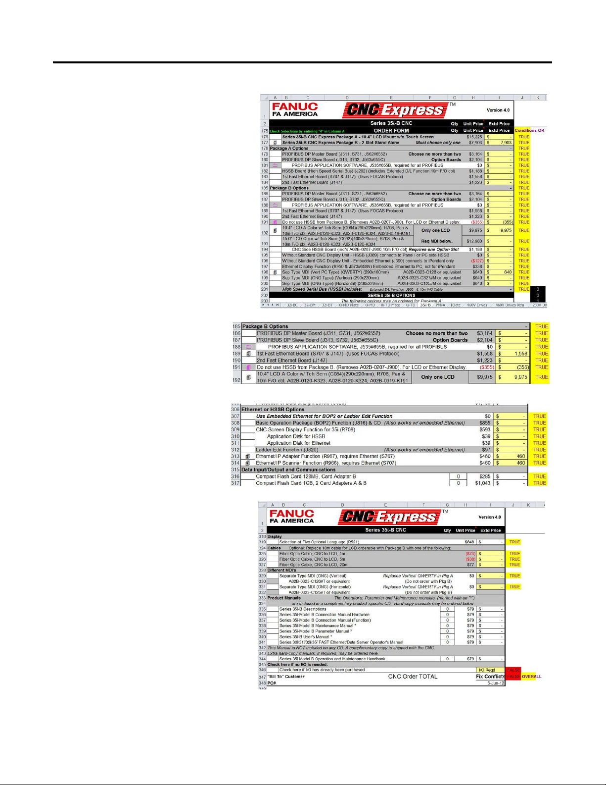
Create CNC System Bill of Materials
1. Select the CNC model, and display
options.
a. Use the tabs near the bottom of the
spreadsheet to navigate to and
select the appropriate CNC model,
based on your machining
requirements.
For the CNC Work Cell example, a
35i-B CNC is selected.
The 35i-B tab is displayed.
Rockwell Automation Publication IASIMP-QS034A-EN-P - October 2012 23
Page 24
Chapter 1 Architecture and Hardware Selection
TIP
b. Use the cells in the spreadsheet to
navigate to and select the
appropriate CNC package, based
on your specific application
requirements.
The 35i-B selections are displayed.
c. Use the cells in the
spreadsheet to navigate to
and select the appropriate
EtherNet/IP options.
d. Use the cells in the spreadsheet to
navigate to and select the
appropriate displays and options.
When all options are selected the
cell at the bottom of the tab (J347)
will display either a TRUE
OVERALL or FALSE
OVERALL status. Make the
appropriate corrections until the
status reads TRUE OVERALL.
The Status is FALSE until the I/O
selection has been satisfied in
the next step.
The 35i-B configuration is now complete.
24 Rockwell Automation Publication IASIMP-QS034A-EN-P - October 2012
Page 25
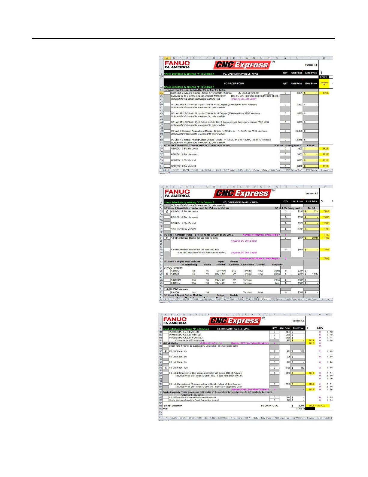
2. Select the System I/O.
TIP
a. Use the tabs near the bottom of the
spreadsheet to navigate to and select
the IOetc tab, for I/O selection.
The IOetc tab is displayed.
b. Use the cells in the spreadsheet to
navigate to and select the
appropriate I/O modules, based on
your specific application
requirements.
Architecture and Hardware Selection Chapter 1
The 35i-B selections are displayed.
c. Use the cells in the spreadsheet to
navigate to and select the
appropriate I/O and options.
When all options are selected the
cell at the bottom of the tab (U268)
will display either a TRUE
OVERALL or FALSE OVERALL
status. Make the appropriate
corrections until the status reads
TRUE OVERALL.
The Status is FALSE until the
I/O selection has been satisfied
in the next step.
The I/O configuration is now complete.
Rockwell Automation Publication IASIMP-QS034A-EN-P - October 2012 25
Page 26
Chapter 1 Architecture and Hardware Selection
3. Select the drives and motors for the
application
a. Use the tabs near the bottom of the
spreadsheet to navigate to and
select the appropriate voltage for
the drives, based on your system
power voltage.
For the CNC Work Cell example,
460V drives is selected.
The 460V drives tab is displayed.
b. Use the cells in the spreadsheet to
navigate to and select the
appropriate motors and drives,
based on your specific application
requirements.
The 460V drives selections are
displayed.
c. Use the cells in the spreadsheet to
navigate to and select the
appropriate motor and drive
options. When all options are
selected the cell at the bottom of the
tab (U801) will display either a
TRUE OVERALL or FALSE
OVERALL status. Make the
appropriate corrections until the
status reads, TRUE OVERALL.
The 460V drives configuration is now
complete.
26 Rockwell Automation Publication IASIMP-QS034A-EN-P - October 2012
Page 27
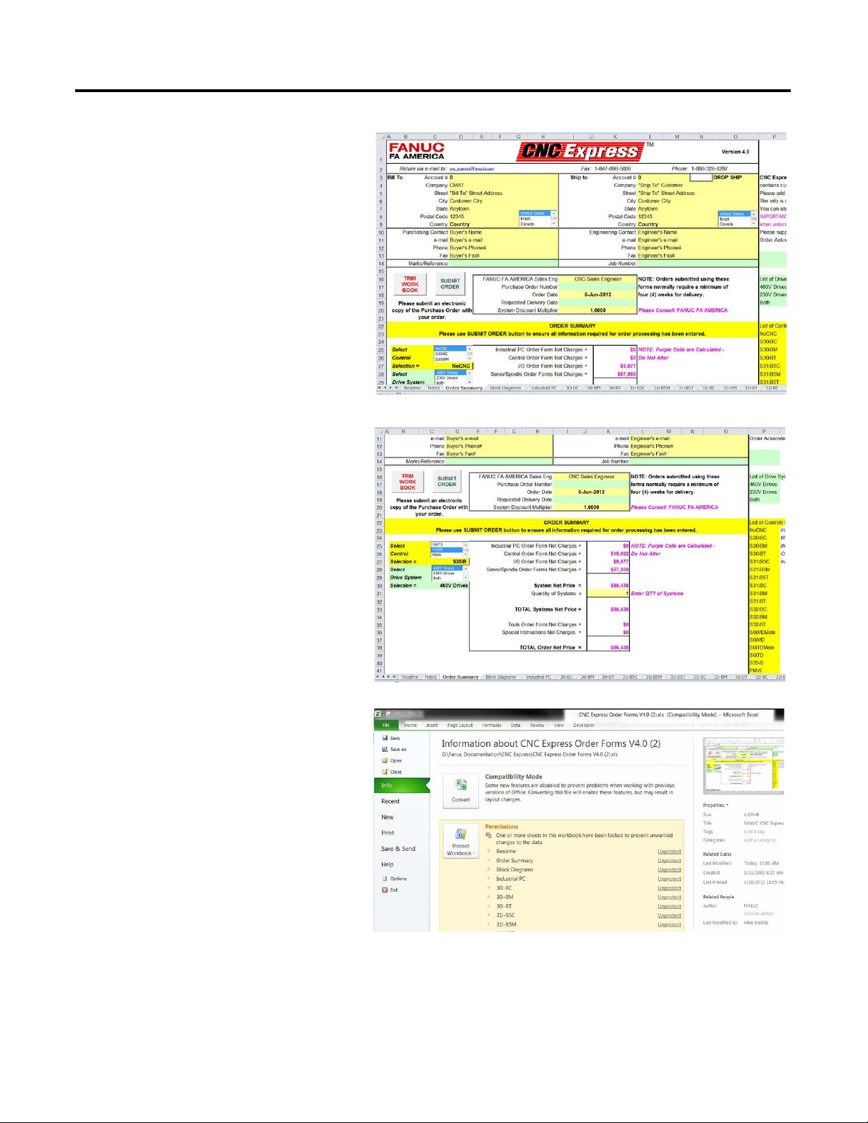
4. Review the complete CNC
configuration.
a. Use the tabs near the bottom of the
spreadsheet to navigate to and click
the Summary tab.
The Summary tab is now displayed.
b. Use the cells in the spreadsheet to
navigate to and select the
appropriate CNC control, and drive
system selection. When the system
is configured properly, the pricing is
shown. If the configured solution is
not correct, fix conflicts are
displayed in the value fields.
Architecture and Hardware Selection Chapter 1
The CNC BOM configuration is
now complete.
5. Name and save the BOM project file.
a. From the File menu, choose Save
As.
Rockwell Automation Publication IASIMP-QS034A-EN-P - October 2012 27
Page 28
Chapter 1 Architecture and Hardware Selection
b. Type a new BOM project file name.
By creating a new BOM project file
specifically for your application, you
preserve the initial toolkit file for
future reference.
In this example, the file was named
CNC_Work_Cell_BOM.
6. Repeat step 1…step 5 for each CNC in
your system.
The BOMs can now be submitted to
FANUC for purchase. We recommend that
your local FANUC representative review
and approve the configuration prior to
purchase.
Create Supervisory Controller and Safety System Bill of Materials
Refer to the Drives and Motion Accelerator Toolkit for creating a supervisory controller bill of materials that
includes Rockwell Automation Kinetix or PowerFlex drives. For a copy of the DVD, contact your local Rockwell
Automation distributor or sales representative.
• Drives and Motion Accelerator Toolkit DVD, publication IASIMP-SP017.
Refer to the Safety Accelerator Toolkit for creating a safety system bill of materials that includes Rockwell
Automation GuardLogix controller and Guard I/O.
• Safety Accelerator Toolkit DVD, publication SAFETY-CL002.
28 Rockwell Automation Publication IASIMP-QS034A-EN-P - October 2012
Page 29
Chapter
CNC Power Example
CNC I/O Example
CNC System Layout Example
2
System Layout and Wiring
In this chapter you select CNC layout and wiring drawings from a library of drawings in AutoCAD .dwg, .dxf, or
.pdf formats to start your system drawing set. If you are using AutoCAD or AutoCAD Electrical software, you
can also take advantage of the drawing editing steps included in this chapter. The library’s device wiring
references and attributes move with the devices as you edit your power drawing set.
You will use the Drives and Motion Accelerator Toolkit DVD, publication IASIMP-SP017, and/or Safety
Accelerator Toolkit DVD, publication SAFETY-CL002, to assemble your drawing set for the Rockwell
Automation components in your system.
Figure 2 - CNC Power, I/O, and Layout Drawing Examples
Rockwell Automation Publication IASIMP-QS034A-EN-P - October 2012 29
Page 30

Chapter 2 System Layout and Wiring
This section uses the CNC Work Cell application example to help you understand how to use the drawing
libraries. The CNC Work Cell includes the following main devices:
• Two FANUC 35i-B CNC systems
• Two Kinetix 6500 servo drives and motors
• One GuardLogix safety controller and EtherNet/IP network module
Before You Begin
Complete your system architecture and hardware selection (see Chapter 1).
What You Need
• CNC Machining Accelerator Toolkit DVD, publication IASIMP-SP018. For a copy of the DVD, contact
your local Rockwell Automation distributor or sales representative.
• AutoCAD Electrical software to open the DWG or DXF files.
• Adobe Reader software to open PDF files.
• System Design for Control of Electrical Noise Reference Manual, publication GMC-RM001.
• System Design for Control of Electrical Noise Video, publication GMC-SP004.
• If Rockwell Automation Kinetix or PowerFlex Drives are used in the system, the Drives and Motion
Accelerator Toolkit DVD is required, publication IASIMP-SP017. For a copy of the DVD, contact your
local Rockwell Automation distributor or sales representative.
• If Rockwell Automation GuardLogix safety controller and safety components are used in the system, the
Safety Accelerator Toolkit DVD is required, publication SAFETY-CL002. For a copy of the DVD,
contact your local Rockwell Automation distributor or sales representative.
30 Rockwell Automation Publication IASIMP-QS034A-EN-P - October 2012
Page 31

Follow These Steps
TIP
Start
page 31
Select FANUC CNC Drawings
from Drawing Library
page 34
Edit FANUC CNC Drawing Set
Assemble and Edit Your
GuardLogix System Drawing Set
page 44
Complete the following steps to create your system layout and wiring drawings.
System Layout and Wiring Chapter 2
Select FANUC CNC Drawings from Drawing Library
The CNC drawing library is organized by these drawing file types:
• AutoCAD Electrical .dwg
• AutoCAD .dxf
• Adobe PDF
The drawings are examples only, and may not reflect your application. There are many different models of
FANUC CNCs and drive combinations available. This toolkit does not detail all possible combinations. This
toolkit uses the 35i-B CNC as an example.
If you do not have CAD software that is compatible with the .dwg/.dxf formats, the PDF files provide an excellent
reference library for wiring all your system devices.
Rockwell Automation Publication IASIMP-QS034A-EN-P - October 2012 31
Page 32

Chapter 2 System Layout and Wiring
1. Create a project folder.
For the CNC Work Cell
example, the
CNC_Work_Cell folder was
created.
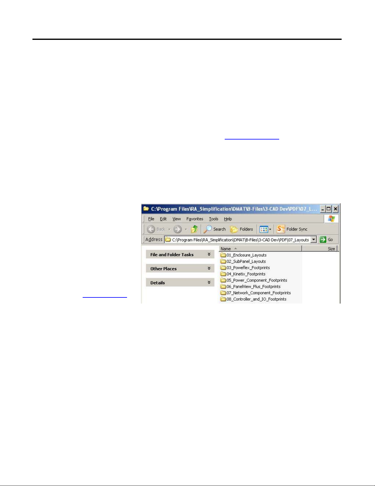
2. Browse to the CNC CAD
Drawing Library on the
CNC toolkit DVD and
select the DWG Format
Drawings, DXF Format
Drawings, or PDF Format
Drawings directory.
Each drawings directory include these files in their respective
files formats.
All drawings are associated with the FANUC CNCs, with the
exception of these three drawings:
• The 07_PLC_1791DS_IB16 and
11_PLC_1791DS_IB4XOW4 drawings are examples of
Rockwell Automation Guard I/O showing the safety I/O
interface with the FANUC Dual Check I/O.
• The 15_CNC_Ethernet_Communication drawing includes
an example of EtherNet/IP communication with the
Rockwell Automation GuardLogix controller, PanelView
Plus, and Kinetix/PowerFlex drives.
32 Rockwell Automation Publication IASIMP-QS034A-EN-P - October 2012
Page 33

3. Copy the entire set of drawings in this folder.
4. Paste the drawing you copied into the
Project Drawings folder.
System Layout and Wiring Chapter 2
Rockwell Automation Publication IASIMP-QS034A-EN-P - October 2012 33
Page 34

Chapter 2 System Layout and Wiring
Edit FANUC CNC Drawing Set
These steps provide general instructions for how to maximize the use of the toolkit’s drawing library in creating a
complete CNC system layout and wiring drawing set. We recommend AutoCAD or AutoCAD Electrical
software to take full advantage of the drawing editing steps and the library’s device wiring references and
attributes that move with the devices as you edit your project drawing set. Some of the initial project creation
steps are illustrated by using AutoCAD Electrical software, but most are generic and can be used with a variety of
software drawing packages.
Create a New Project
1. Open your drawing software.
2. Create and name your new project.
3. Add and select the toolkit library drawings
you copied in the previous section.
34 Rockwell Automation Publication IASIMP-QS034A-EN-P - October 2012
Page 35

System Layout and Wiring Chapter 2
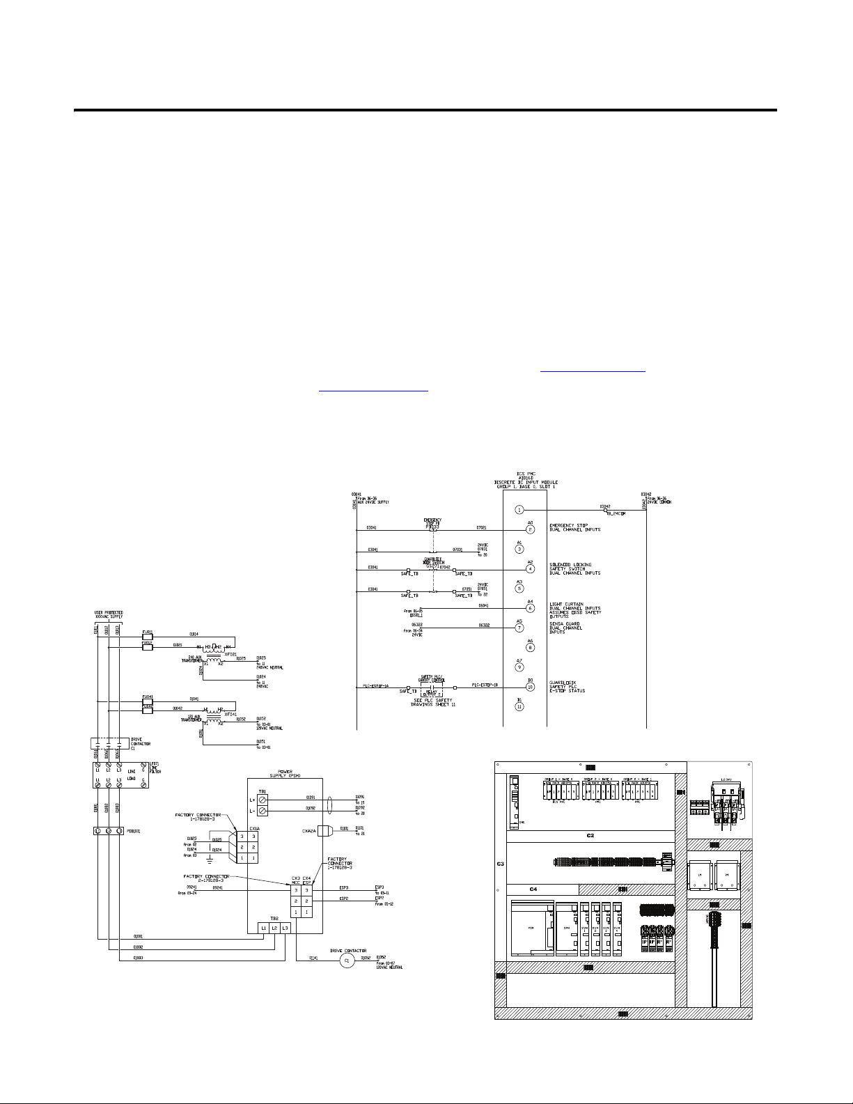
Edit CNC Power Drawings
1. Open your initial CNC power drawing that includes the main power distribution components,
01_CNC_Drives_w_Dual Check IO.dwg. See Figure 3 on page 36.
2. Modify this drawing for your project.
The 01_CNC_Drives_w_Dual Check IO includes the main power distribution components as well as the
CNC power supply, one spindle module and motor, and one servo module and motor. Typically you
would have at least these components in each of your CNC systems. Copy this drawing for every CNC you
have in your system.
For the CNC Work Cell application example, there are two FANUC CNC systems, so this drawing would
be copied for the second CNC system.
3. Open the 02_CNC_Drives_w_Dual_Check_IO drawing and modify for your project. See Figure 4 on
page 37.
The 02_CNC_Drives_w_Dual_Check_IO drawing includes three additional servo modules and motors.
You will most likely copy this drawing for every CNC you have in your system. Delete the servos and
motors not required for you system.
For the CNC Work Cell application example there are two FANUC CNC systems, so this drawing would
be copied for the second CNC system, and one spindle module and motor would be deleted from each
drawing.
4. Open the remaining CNC control power distribution drawings and edit power connections and devices as
necessary.
The drawings include:
• 03_CNC_Control_Power_Distribution
• 04_CNC_Control_Power_Distribution
• 05_CNC_Monitored_Safety_Relay
• 06_CNC_24VDC_Safety_Power
• 17_CNC_Power_Connections
• 18_CNC_Cable_Connections
Rockwell Automation Publication IASIMP-QS034A-EN-P - October 2012 35
Page 36

Chapter 2 System Layout and Wiring
Figure 3 - 01_CNC_Drives_w_Dual Check IO Drawing
36 Rockwell Automation Publication IASIMP-QS034A-EN-P - October 2012
Page 37
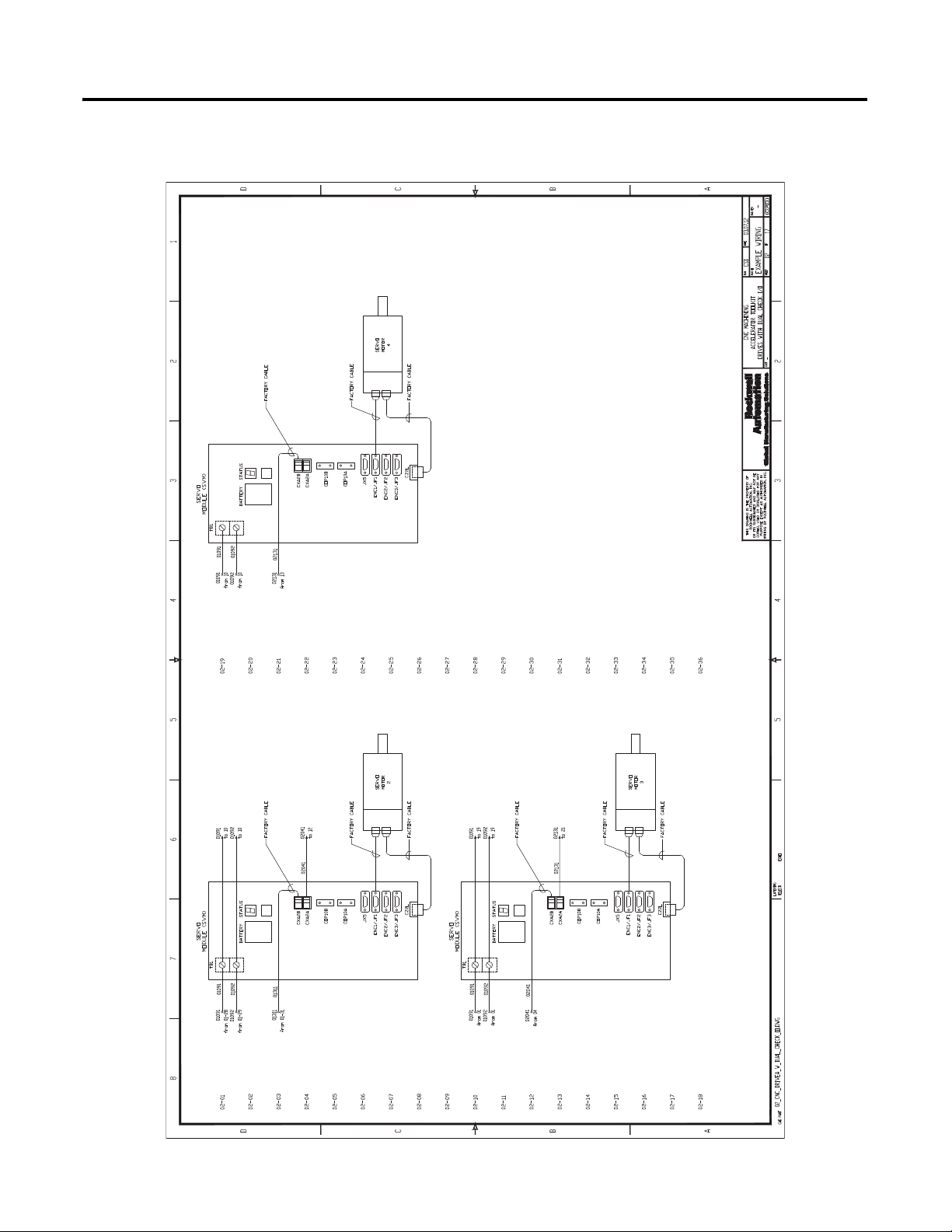
Figure 4 - 02_CNC_Drives_w_Dual Check IO Drawing
System Layout and Wiring Chapter 2
Rockwell Automation Publication IASIMP-QS034A-EN-P - October 2012 37
Page 38

Chapter 2 System Layout and Wiring
Edit CNC Safety and Standard I/O Drawings
1. If FANUC Dual Check Safety is incorporated into your project, open the following drawings for your
project:
• 07_CNC_AID16D_Dual_Check_IO_Module
• 08_CNC_AID16D_Dual_Check_IO_Module
• 09_CNC_AOR8G_Dual_Check_IO_Module
2. Modify your Dual Check safety input module drawings.
The Dual Check safety input module drawings 07_CNC_AID16D_Dual_Check_IO_Module and
08_CNC_AID16D_Dual_Check_IO_Module include a variety of input device examples to include in
your drawing set.
a. Copy and paste input devices to match your application. See Figure 5 on page 39.
In addition to safety devices, the 07_CNC_AID16D_Dual_Check_IO_Module drawing includes
example dual channel connections from the GuardLogix Guard I/O outputs.
3. Modify your Dual Check safety output module drawing.
The Dual Check safety output module drawing, 09_CNC_AOR8G_Dual_Check_IO_Module includes
a few output device examples to include in your drawing set.
a. Copy and paste output devices to match your application. See Figure 6 on page 40
In addition to safety devices the 09_CNC_AOR8G_Dual_Check_IO_Module drawing includes example
dual channel connections to the GuardLogix Guard I/O inputs.
4. If using GuardLogix as a supervisory safety controller for your CNC cell in your project, then open and
modify the following drawings for your project:
• 07_PLC_1791DS_IB16
• 11_PLC_1791DS_IB4XOW4
These drawings show examples of the dual channel input and output connections from the FANUC Dual
Check Safety I/O.
You may copy these connections to other Guard I/O modules within the Safety Accelerator Toolkit
drawings.
5. Open and modify the following standard CNC I/O drawings for your project:
• 12_CNC_AOR16G_Output_Module
• 13_CNC_Digital_Inputs
• 14_CNC_Relay_Outputs
These drawings include a variety of input and output device examples to include in your drawing set.
38 Rockwell Automation Publication IASIMP-QS034A-EN-P - October 2012
Page 39

Figure 5 - 07_CNC_AID16D_Dual_Check_IO_Module Drawing
System Layout and Wiring Chapter 2
Rockwell Automation Publication IASIMP-QS034A-EN-P - October 2012 39
Page 40

Chapter 2 System Layout and Wiring
Figure 6 - 09_CNC_AOR8G_Dual_Check_IO_Module Drawing
40 Rockwell Automation Publication IASIMP-QS034A-EN-P - October 2012
Page 41
System Layout and Wiring Chapter 2
Edit System Communication Drawings
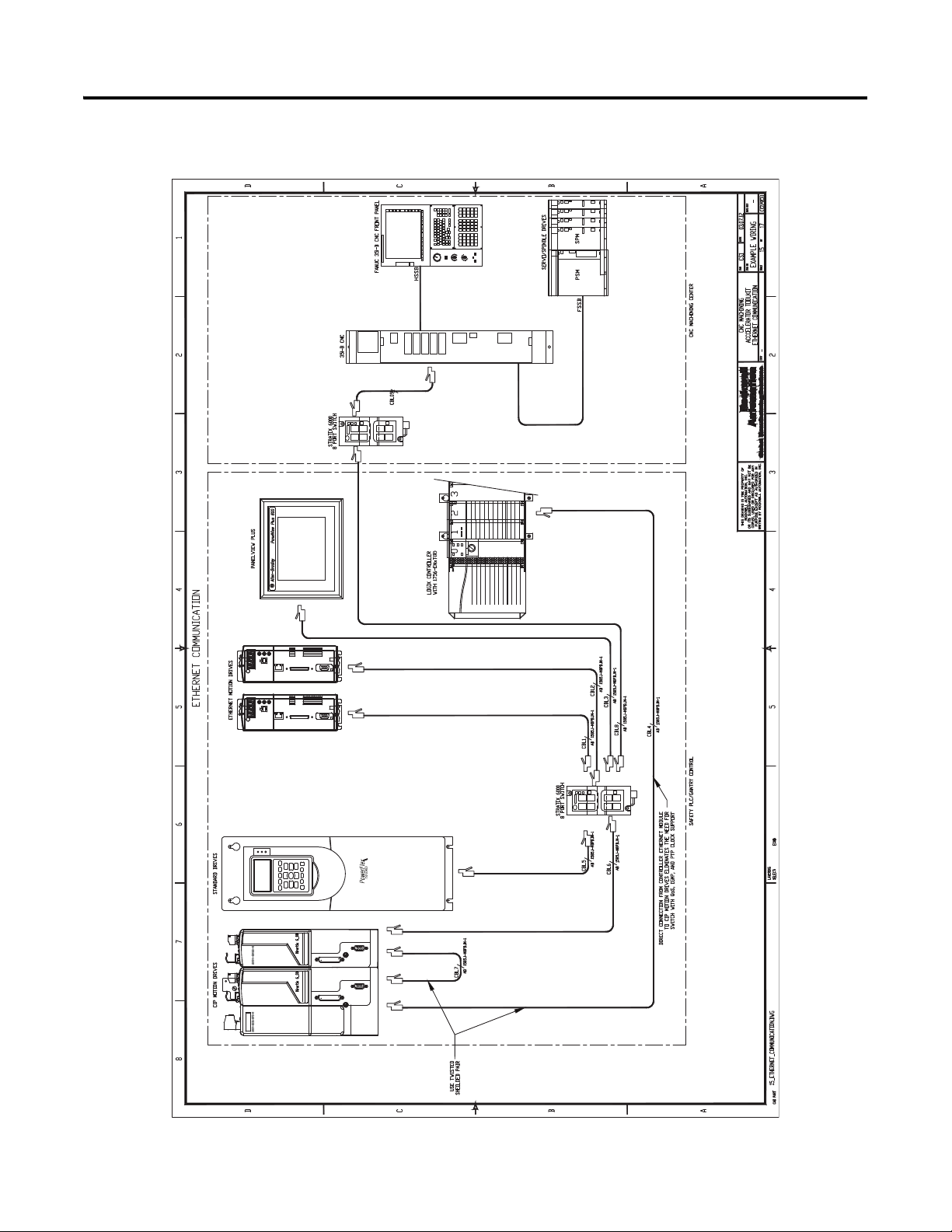
1. Open the following communication drawings to access your project's EtherNet/IP configuration drawings:
• 15_CNC_Ethernet_Communication
• 16_CNC_Ethernet_Switch
• 18_CNC_Cable_Connections
2. Delete and or copy network devices to match your system requirements.
The 15_CNC_Ethernet_Communication drawing is shown in Figure 7 on page 42. It includes both
FANUC CNC system and Rockwell Automation GuardLogix, PanelView, and Kinetix/PowerFlex Drive
EtherNet/IP connections. Simply delete and/or copy EtherNet/IP devices to match your project
requirements.
The 16_CNC_Ethernet_Switch and 18_CNC_Cable_Connections drawings include references to
FANUC CNC system and Rockwell Automation EtherNet/IP devices, cables, and connections. Delete
and or copy components to match your project requirements.
3. Access other Rockwell
Automation device footprints
required for your application.
To access Rockwell
Automation Kinetix or
PowerFlex drive system
footprints, including HMI
and other power components,
use the Drives and Motion
Accelerator Toolkit DVD,
publication IASIMP-SP017.
Navigate to the CAD drawing
libraries layout section
directories for a variety of
device footprints.
Rockwell Automation Publication IASIMP-QS034A-EN-P - October 2012 41
Page 42
Chapter 2 System Layout and Wiring
Figure 7 - 15_CNC_Ethernet_Communication Drawing.
42 Rockwell Automation Publication IASIMP-QS034A-EN-P - October 2012
Page 43

Edit CNC System Layout Drawing
CNC Subpanel Layout Drawing
CNC Enclosure Layout Drawing
1. Open the panel layout drawing for your application.
For the CNC Work Cell application example, the
19_CNC_Panel_Layout.dwg file is opened.
The panel layout drawing includes sub-panel and enclosure
drawings. The panel is designed to accommodate
best-practice techniques used to minimize electrical noise.
Refer to the System Design for Control of Electrical Noise
Reference Manual, publication GMC-RM001.
2. Delete, replace, or add
component footprints to your
panel layout drawing.
System Layout and Wiring Chapter 2
To access Rockwell
Automation power
components, use the Drives
and Motion Accelerator
Toolkit DVD, publication
IASIMP-SP017. Navigate to
the CAD drawing libraries
layout section directories for a
variety of device footprints.
3. Delete, replace, or add
components to your
enclosure drawing.
To access Rockwell
Automation HMI or power
components, use the Drives
and Motion Accelerator
Toolkit DVD, publication
IASIMP-SP017
the CAD drawing libraries
layout section directories for
a variety of device footprints.
. Navigate to
Rockwell Automation Publication IASIMP-QS034A-EN-P - October 2012 43
Page 44

Chapter 2 System Layout and Wiring
LIM Module
AC Line Filter
System Layout Example
Drive Power Example
Drive I/O Example
Assemble and Edit Your GuardLogix System Drawing Set
If Rockwell Automation Kinetix and PowerFlex drives are to be used in your system, use the Drives and Motion
Accelerator Toolkit DVD, publication IASIMP-SP017, to assemble and edit your GuardLogix system drawing
set. For a copy of the DVD, contact your local Rockwell Automation distributor or sales representative.
44 Rockwell Automation Publication IASIMP-QS034A-EN-P - October 2012
Page 45

System Layout and Wiring Chapter 2
Drive Safety Wiring
Title
Safety Controller Power
Other Safety Devices
Guard I/O Module Wiring
Drive I/O
Safety Controller Network Drawings
Safety Controller I/O
Ethernet Switch Wiring
Panel Layout Drawings
If Rockwell Automation GuardLogix safety controller and safety components are used in the system, use the
Safety Accelerator Toolkit DVD, publication SAFETY-CL002, to assemble your safety wiring and layout
drawing set. For a copy of the DVD, contact your local Rockwell Automation distributor or sales representative.
Rockwell Automation Publication IASIMP-QS034A-EN-P - October 2012 45
Page 46

Chapter 2 System Layout and Wiring
Notes:
46 Rockwell Automation Publication IASIMP-QS034A-EN-P - October 2012
Page 47

Chapter
3
FANUC CNC Configuration
In this chapter you initially configure your FANUC 30i-B, 31i-B, 32i-B, or 35i-B CNC, set up the CNC
communication, and create a new project file for your CNC application. The intent is to provide a quick setup
for an EtherNet/IP connection between a Rockwell Automation ControlLogix/GuardLogix PLC and a
FANUC 30i-B, 31i-B, 32i-B, or 35i-B CNC.
The overall CNC configuration and parameterization is not being addressed by this quick start, and is the
responsibility of the machine tool builder.
Before You Begin
• Complete your system architecture and hardware selection (refer to Chapter 1).
• Complete your system layout and wiring (refer to Chapter 2).
What You Need
• The CNC Machining Accelerator Toolkit DVD, publication IASIMP-SP018. For a copy of the DVD,
contact your local Rockwell Automation distributor or sales representative
• FANUC LADDER III software, version 6.8 or later
• USB flash drive
• FANUC Series 30i/31i/32i/35i –MODEL B, EtherNet/IP Adapter function, publication
TMN11003E_B-64014EN@04-2.pdf
• FANUC Series 30i/31i/32i/35i -MODEL B, FANUC Power Motion i -MODEL A EtherNet/IP Scanner
function, publication TMN11095E_B-64014EN@04-3.pdf
Rockwell Automation Publication IASIMP-QS034A-EN-P - October 2012 47
Page 48
Chapter 3 FANUC CNC Configuration
Start
Initial FANUC CNC
Configuration
page 48
Logic Configuration
page 68
Follow These Steps
Complete these steps to configure your FANUC 30i-B, 31i-B, 32i-B, or 35i-B CNC for your application.
Initial FANUC CNC Configuration
In this example, you set up your FANUC 30i-B, 31i-B, 32i-B, or 35i-B CNC to allow configuration parameters
to be modified, to receive configuration parameters from external sources, and to select the high speed Ethernet
option.
System Powerup
Locate the CNC systems power button, then press to apply power.
48 Rockwell Automation Publication IASIMP-QS034A-EN-P - October 2012
Page 49

FANUC CNC Configuration Chapter 3
Parameter Write Enable
Set the parameter write enable (PWE, 8900#0) bit to allow the configuration parameter changes described in the
following sections.
1. Press the OFS/SET button on the
QWERTY MDI Panel to open the
SETTING (HANDY) screen.
Either the OFFSET screen or the
SETTING screen is displayed. On first
powerup, the OFFSET screen is displayed.
2. Press the SETTING button to call the
SETTING screen.
Rockwell Automation Publication IASIMP-QS034A-EN-P - October 2012 49
Page 50

Chapter 3 FANUC CNC Configuration
IMPORTANT
3. Use the arrow keys on the MDI panel to move to the desired
selections.
4. Prior to setting the parameter, be sure that MDI modes has been
selected by pressing the button on the CNC main panel.
5. Enter 1 from the numeric entry, then press INPUT to set the
parameter write enable bit (PWE, 8900#0). This lets you set the
parameters, and configure the CNC for use.
6. Setting this may cause an alarm to be triggered and displayed.
Cancel the alarm by pressing RESET on the MDI Panel. You will
then have to open the SETTING screen again as described above.
7. Turn the parameter write enable key switch to the on position.
This will take affect after the initial program has
been downloaded later in this chapter.
50 Rockwell Automation Publication IASIMP-QS034A-EN-P - October 2012
Page 51

FANUC CNC Configuration Chapter 3
High Speed Ethernet Option
Select the high speed Ethernet option to be used. This enables the fast Ethernet board to be used, and is required
for the CNC EtherNet/IP option.
1. Press the SYSTEM function key from the
MDI panel.
The system PARAMETER screen is
displayed.
2. Press either the + softkey or the right arrow
function key to advance to the chapter
selection for PMC configuration.
Rockwell Automation Publication IASIMP-QS034A-EN-P - October 2012 51
Page 52

Chapter 3 FANUC CNC Configuration
The chapter selection screen to display the
PMC configuration options is displayed.
3. Press the PMC CONFIG softkey.
4. Press either the + softkey or the right arrow
function key to advance to the chapter
selection for PMC online configuration, then
press ONLINE.
The chapter selection screen to display the
PMC online configuration options is
displayed.
5. Use the arrow keys on the
MDI panel to move to the
HIGH SPEED field, then
select USE.
The fast ethernet board is
now available to be
configured for the
EtherNet/IP application.
52 Rockwell Automation Publication IASIMP-QS034A-EN-P - October 2012
Page 53

FANUC CNC Configuration Chapter 3
Configure Ethernet Module
In this example, you configure the fast Ethernet board for communicating to the Supervisory PLC, and an offline
development personal computer. See CNC to Controller Communication on page 208 for location of the fast
Ethernet board.
IP Address, Subnet Mask, and Port Number
Configure the IP Address of the fast Ethernet board to allow
network connectivity.
1. Press the SYSTEM function key from the MDI panel.
The system PARAMETER screen is
displayed.
2. Press either the + softkey or the right arrow
function key to advance to the chapter
selection for Ethernet.
Rockwell Automation Publication IASIMP-QS034A-EN-P - October 2012 53
Page 54
Chapter 3 FANUC CNC Configuration
The chapter selection screen to display the
fast Ethernet options is displayed.
3. Press the ETHERNET softkey to view the
settings and selections of the fast Ethernet
board.
4. Press the COMMON softkey to view the
common settings of the fast Ethernet board. It
may be necessary to press either the + softkey
or the right arrow function key to advance to
the chapter selection for Ethernet common.
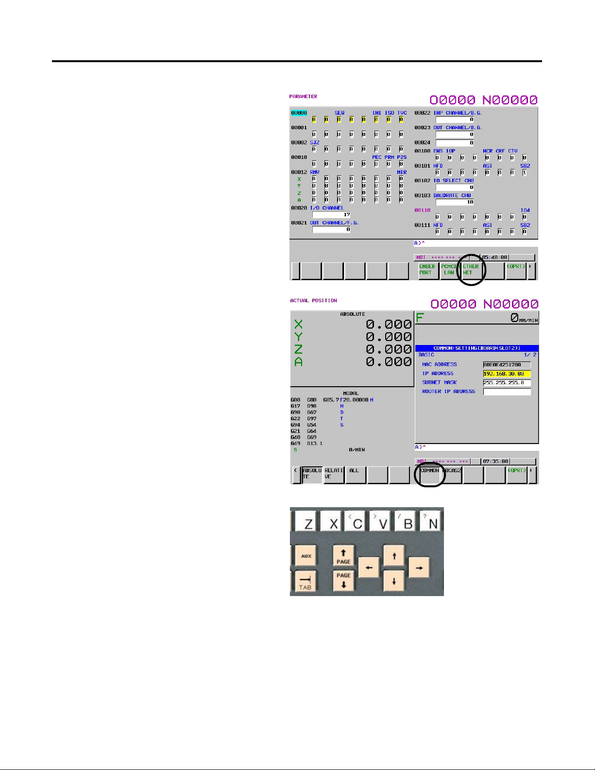
5. Use the arrow keys on the MDI panel to move
to the IP ADDRESS field, then enter the IP
address for your configuration by using the
number keys on the MDI panel. The example
uses the IP address 192.168. 30.80
6. Use the arrow keys on the MDI panel to move
to the SUBNET MASK field, then enter the
mask for your configuration by using the
number keys on the MDI panel. The example
is using the mask 255.255.255.0
54 Rockwell Automation Publication IASIMP-QS034A-EN-P - October 2012
Page 55
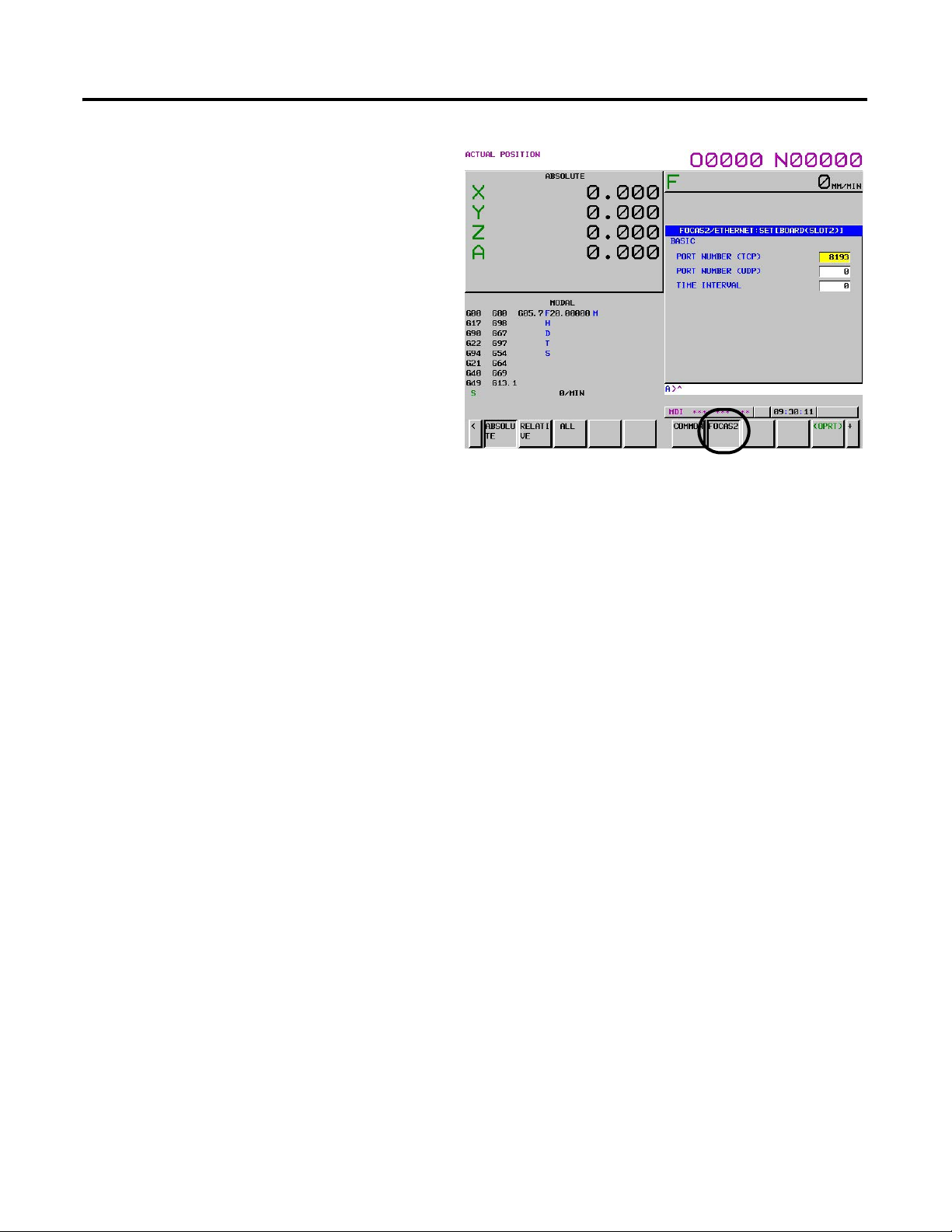
7. Press the FOCAS2 softkey to view the
FOCAS2/ETHERNET settings of the fast
Ethernet board.
8. Verify that PORT NUMBER (TCP) is 8193.
This is the default port number, and also the
default configuration for the offline
development software packages.
The Ethernet board is now configured for the
connection to the offline development
personal computer.
FANUC CNC Configuration Chapter 3
Rockwell Automation Publication IASIMP-QS034A-EN-P - October 2012 55
Page 56

Chapter 3 FANUC CNC Configuration
Create a New Project File
Throughout the rest of this chapter, the controller and network configuration procedures are written specifically
for an S35i-B CNC. Steps for other FANUC CNC models are similar. It is assumed that FANUC LADDER III
has been installed and is operational on the development personal computer being used for this task.
The process of creating a new project is based on using an example file that has been pre-written. You must
change the name of the file from the toolkit, to something that is relevant to the application and task being
created.
1. From the Start menu, launch the FANUC
LADDER III software.
2. From the File menu, choose Open
Program.
The Open dialog box appears.
3. Locate the CMAT 35i-B.LAD
file from the CNC Machining
Accelerator toolkit DVD, and
select OPEN.
56 Rockwell Automation Publication IASIMP-QS034A-EN-P - October 2012
Page 57

The sample program opens, and is ready for
editing.
Change the CNC model for your specific
application.
FANUC CNC Configuration Chapter 3
4. From the File menu, choose PMC Type
changed and save.
Rockwell Automation Publication IASIMP-QS034A-EN-P - October 2012 57
Page 58

Chapter 3 FANUC CNC Configuration
5. Select the model.
6. Select the control configuration for the
specific application.
58 Rockwell Automation Publication IASIMP-QS034A-EN-P - October 2012
Page 59

7. From the File menu, choose Save As.
8. Save as a different file name, in a
different location.
FANUC CNC Configuration Chapter 3
9. Click OK and save with the default
options.
10. Click OK.
You are now ready to begin editing the
file for your specific application.
Rockwell Automation Publication IASIMP-QS034A-EN-P - October 2012 59
Page 60
Chapter 3 FANUC CNC Configuration
Download FANUC LADDER III Software Project to the FANUC S35i-B CNC
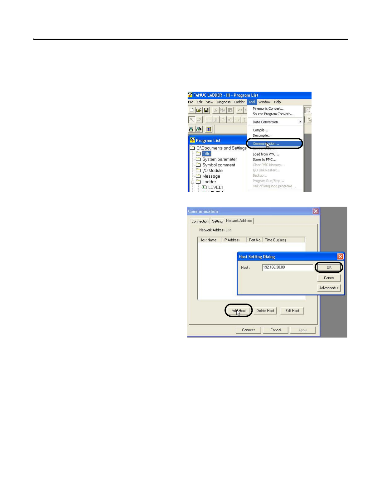
1. Open your FANUC LADDER III project file.
2. From the Tool menu, choose Communication.
The Communication dialog box opens.
3. Click the Network Address tab and click Add
Host.
4. Type in the IP address of the CNC that you
are working on, then click OK.
The host has now been entered into the
address list.
60 Rockwell Automation Publication IASIMP-QS034A-EN-P - October 2012
Page 61

5. Click Connect to establish communication
with the CNC.
6. After the successful connection has been
established, click Close to close the
dialog box.
FANUC CNC Configuration Chapter 3
7. From the Tool menu, choose Store to
PMC.
Rockwell Automation Publication IASIMP-QS034A-EN-P - October 2012 61
Page 62

Chapter 3 FANUC CNC Configuration
The Program transfer wizard dialog box
opens.
8. Click Next, then Finish.
9. After the download is complete, the
Program transfer wizard dialog box
closes, and the Program RUN/STOP
dialog box appears. Click Yes to run
the program.
The FANUC LADDER III PMC program
is now downloaded and running within the
s35i-B CNC.
62 Rockwell Automation Publication IASIMP-QS034A-EN-P - October 2012
Page 63

FANUC CNC Configuration Chapter 3
USB External Device
Define the USB port as the punch/reader port. This lets you receive and save configuration files to an external
portable USB device.
1. Use the arrow keys as previously described to move to
the I/O CHANNEL setting and enter the value 17. You
will see the value displayed on the entry line beneath the
settings.
2. Press INPUT as previously described, to change the
parameter. You will now see the value 17 displayed in the
parameter.
The USB port has now been selected as the I/O channel
for the punch/reader function.
Rockwell Automation Publication IASIMP-QS034A-EN-P - October 2012 63
Page 64
Chapter 3 FANUC CNC Configuration
EtherNet/IP Settings
Configure the EtherNet/IP settings of the fast Ethernet board to allow the communication to the supervisory
PLC, and the connection to the Rockwell Automation AOP as detailed in Chapter 4.
The EtherNet/IP settings used throughout this quick start are the following CNC data table tags:
• PLC to FANUC tags - R1000 – R1255
• FANUC to PLC tags - R2000 – R2255
A detailed description of these addresses, and
the specific mapping between the PLC and
CNC can be found in the CMAT-IDS.xlsx file.
The path to this file is C:\Program Files\
RA_Simplification\CMAT\A-Files\
4-Controller Logic\02_CNC_Logic.
Refer to the FANUC EtherNet/IP
documentation listed in What You Need on
page 47 of this chapter, if you would like to
change these locations.
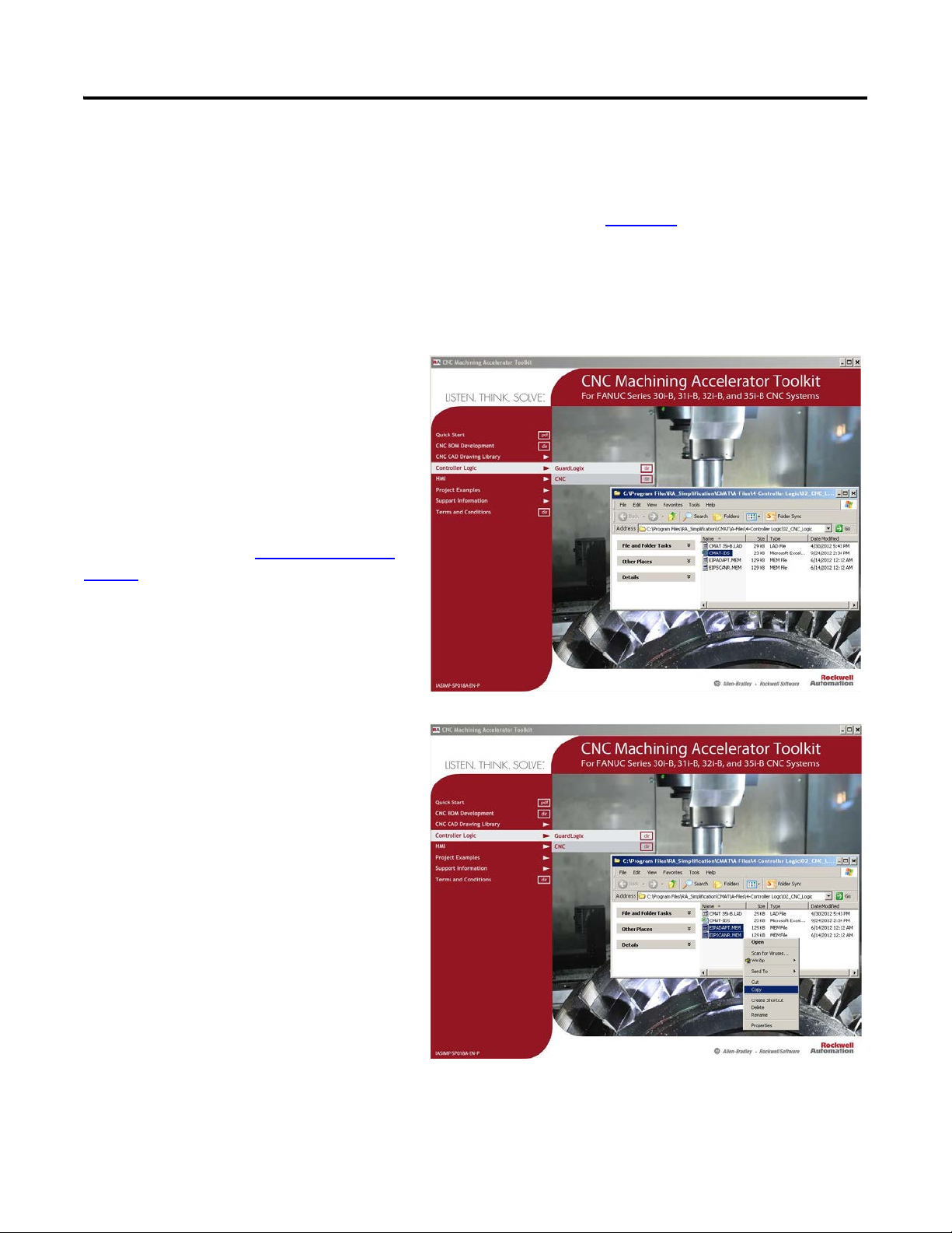
1. Use the CNC Machining Accelerator
Toolkit to navigate to the CNC Logic
folder and copy both EtherNet/IP
configuration files onto an external USB
device.
• EIPADAPT.MEM
• EIPSCANR.MEM
64 Rockwell Automation Publication IASIMP-QS034A-EN-P - October 2012
Page 65

2. Take the USB device and plug it into the
CNC port next to the panel display.
FANUC CNC Configuration Chapter 3
3. Press the SYSTEM function key from the
MDI panel.
The System PARAMETER screen is
displayed.
Rockwell Automation Publication IASIMP-QS034A-EN-P - October 2012 65
Page 66

Chapter 3 FANUC CNC Configuration
4. Press either the + softkey or the right arrow
function key to advance to the chapter
selection for Ethernet network.
The chapter selection screen to display the fast
Ethernet options is displayed.
5. Press the ETHERNET softkey to view the
settings and selections of the fast Ethernet
board.
66 Rockwell Automation Publication IASIMP-QS034A-EN-P - October 2012
Page 67

6. Press either the + softkey or the right arrow
function key to advance to the chapter
selection for EtherNet/IP scanner settings,
EIP S SET.
7. Press the (OPRT) softkey to display available
operations for the EtherNet/IP scanner
settings.
8. Press either the + softkey or the right arrow
function key to advance to the operation
selection for restore.
9. Press the RESTORE softkey to display
available operations for the EtherNet/IP
scanner restore operations.
FANUC CNC Configuration Chapter 3
10. Press the EXECUTE softkey to copy the
parameters from the external USB device to the
CNC parameter memory.
11. Power down the CNC to accept the changes to
the EtherNet/IP settings.
12. Power up the CNC, then repeat step 2
for the Ethernet adaptor settings (at step 6
...step 11
select EIP A SET).
The Ethernet board is now configured for the
connection to the supervisory PLC that uses
the EtherNet/IP protocol.
Rockwell Automation Publication IASIMP-QS034A-EN-P - October 2012 67
Page 68

Chapter 3 FANUC CNC Configuration
IMPORTANT
IMPORTANT
Device
Module(s)
Application
Module(s)
Machine Module
CNC
PMC
MDI Panels
Device
Status
Device
Commands
LCD Display
Machine
Status
Operator
Commands
Operator
Commands
CNC/PMC Logic
CNC Operator Panels
Application
Commands
PLC AOP
Logic Configuration
In this chapter you use the preconfigured PMC logic files and edit them specifically for your application. The
toolkit provides a preconfigured PMC file with application and device modules that significantly speed-up your
application logic development. An initial I/O configuration is provided as well, as an example only.
To assist you in understanding how to best use the preconfigured logic files, the CNC Work Cell application is
used as an example in all of the logic configuration steps.
The overall machine CNC functionality and configuration is not being detailed or explained here. The CNC Machining
Accelerator Toolkit, and this quick start, provide the framework to communicate with the Rockwell Automation
GuardLogix supervisory controller.
In this example, there is a supervisory PLC that manages an entire work cell consisting of a gantry, and two machining
centers. This PMC program is for one of the machining centers, but could be used interchangeably as a starting point.
In this example, the PLC is controlling the machining centers, sending commands over the EtherNet/IP network
to the FANUC CNC devices.
68 Rockwell Automation Publication IASIMP-QS034A-EN-P - October 2012
Page 69

FANUC CNC Configuration Chapter 3
The CNC architecture consists of two central processing units (CPUs), one specifically for the coordinated
machine motion (CNC), and one for the machine I/O and peripheral functions (PMC).
The CNC is the machine module in this example. It consists of proprietary software from FANUC, and is a layer
that is not accessible for modifications. FANUC provides a means to interface with a CNC by using pre-defined
system data table address registers. Refer to the FANUC documentation provided with your CNC for more
information.
Within the PMC, there are application modules and device modules. The modules are described below:
• Application Modules – The application modules execute the machine commands and provide the more
specific application commands for the CNCs functions. These modules must be defined, edited, and
completed for your specific application prior to final commissioning on a CNC machine. To complete the
proper handshaking between the PLC and CNC for the example project, these application modules have
been programmed with timers to simulate a response. Add the custom application code as necessary to
complete the programming for the specific application in these areas.
• Device Modules – The device modules translate the overall machine and application commands, and
provide uniform status and diagnostics from/to the very specific EtherNet/IP device tags. This reduces
much of the non-inventive code required to control and monitor the EtherNet/IP device.
Table 2 - Preconfigured Logic Modules Used in CNC Work Cell Example
Module Type File Names
LEVEL1
LEVEL2
Application
Device
P0001 (OP Panel Path 1)
P0005 (Machine Sequence)
P0010 (Window Functions)
P0023 (Alarm Routine)
P0015 (PLC EIP Input Routine)
P0016 (PLC EIP Output Routine)
Rockwell Automation Publication IASIMP-QS034A-EN-P - October 2012 69
Page 70

Chapter 3 FANUC CNC Configuration
Editing Application Logic Modules and Adding Code
1. Open the FANUC LADDER
III file that was saved previously.
2. Review the logic modules in the
folder tree.
3. Double-click the files to open
and edit the logic for your
specific application
70 Rockwell Automation Publication IASIMP-QS034A-EN-P - October 2012
Page 71

P0001 (OP Panel Path 1)
This application program manages the operator
panel and MDI panel I/O interface. The
Machine mode push buttons, indicator lights,
and feed rate override signals are controlled from
this program routine.
P0005 (Machine Sequence)
FANUC CNC Configuration Chapter 3
This application program manages the
sequencing involved in a machine tool
application. This, along with other programs
(provided by the OEM) specific to the machine
application will control machine I/O, and/or
control overall machine functionality.
Edit this file as necessary to control the machine
to meet the performance specifications required
for the application. To maintain code modularity,
add additional files on a function by function
basis.
Rockwell Automation Publication IASIMP-QS034A-EN-P - October 2012 71
Page 72

Chapter 3 FANUC CNC Configuration
P0010 (Window Functions)
This application program manages the window
functions provided by the CNC. The window
functions allow the PMC program to access
features of the CNC that are not part of the
standard data table interface between the PMC
and CNC (refer to the FANUC documentation
for further details).
This module is used to provide status and
command to the EtherNet/IP device modules.
P0023 (Alarm Routine)
This application program manages the alarming
for the CNC, and also provides status to the
EtherNet/IP device module.
Add application program files as necessary for
your specific application.
72 Rockwell Automation Publication IASIMP-QS034A-EN-P - October 2012
Page 73
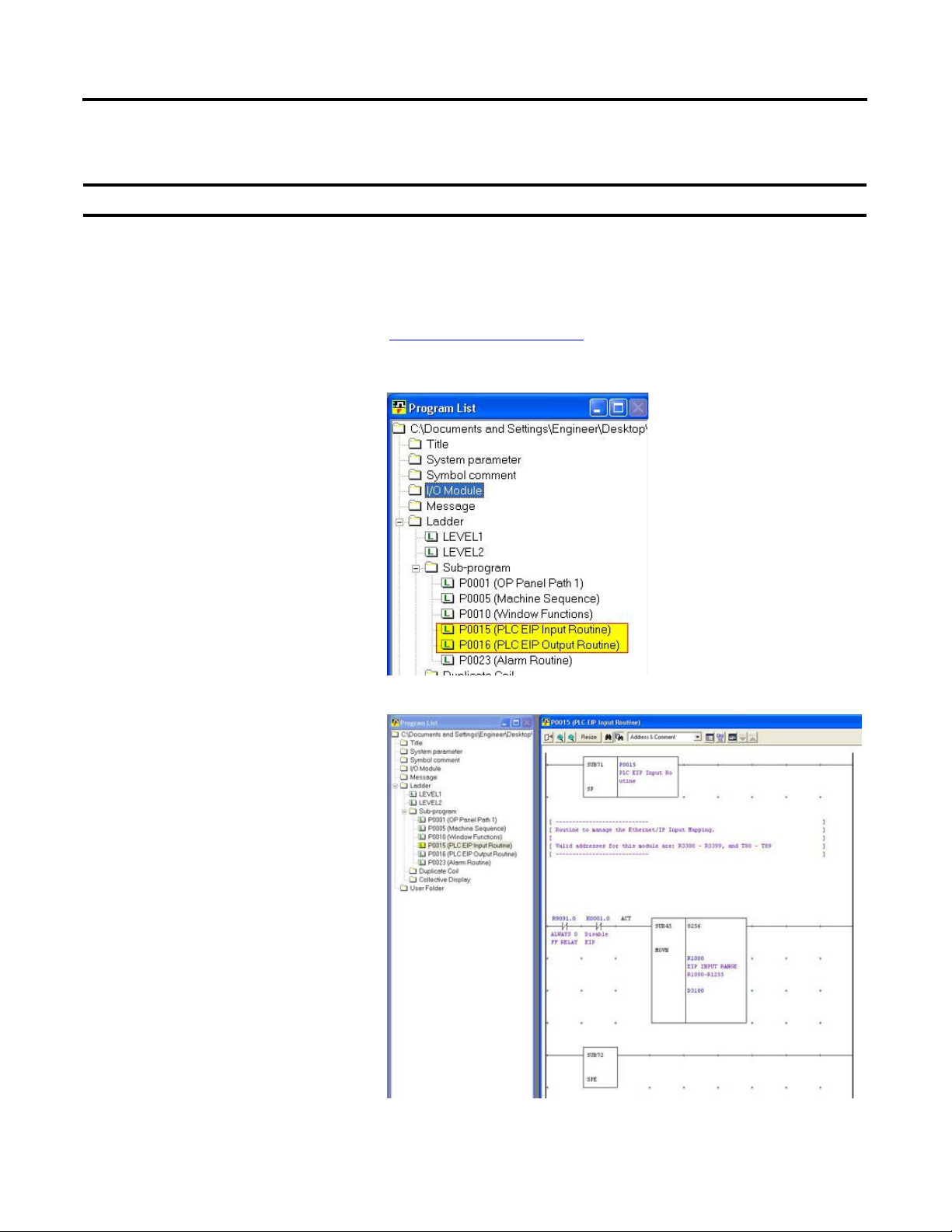
FANUC CNC Configuration Chapter 3
IMPORTANT
Device Logic Modules
These modules are mandatory for the EtherNet/IP communication between the CNC and the PLC.
These pre-defined modules require no modifications to interact with the supervisory PLC and ControlLogix
AOP as described in the following chapters.
If additional functionality is desired, FANUC and Rockwell Automation have provided an open architecture
that can be used. Refer to the documents in What You Need on page 47 for the specific details of the
EtherNet/IP feature.
1. Review the logic modules in the
folder tree.
2. Double-click the files to open the
logic for review.
Rockwell Automation Publication IASIMP-QS034A-EN-P - October 2012 73
Page 74

Chapter 3 FANUC CNC Configuration
P00015 (PLC EIP Input Routine)
This device program moves the 256 bytes from
the data table area previously specified
(R1000…R1255) for the EtherNet/IP option
into a buffered data table that is used throughout
the program by the application modules.
A detailed description of these addresses,
and the specific mapping between the
PLC and CNC, can be found in the
CMAT-IDS.xlsx file.
P00016 (PLC EIP Output Routine)
This device program manages the output data
being sent to the supervisory PLC. The program
uses status information from the application
modules to set a buffered data table area specific
for the functions detailed in the IDS previously
mentioned. Refer to CMAT-IDS.xlsx for the
mapping (as shown in the screen above).
The buffered data table area will then be moved
into the 256 bytes of the data table area
previously specified (R2000…R2255) for the
EtherNet/IP option.
74 Rockwell Automation Publication IASIMP-QS034A-EN-P - October 2012
Page 75

FANUC CNC Configuration Chapter 3
Verify and Save the Project File
When you have finished programming your FANUC CNC application with the FANUC LADDER III
software, verify and save your file.
1. From the Tool menu, choose Compile to
check for errors.
2. Click Exec when the Compile dialog
box opens.
Rockwell Automation Publication IASIMP-QS034A-EN-P - October 2012 75
Page 76

Chapter 3 FANUC CNC Configuration
TIP
3. Click Close after the compile is complete.
If the compile has completed with
no errors, than it is OK to download
to the CNC; otherwise, review the
compile report and return and
correct the errors.
4. Click to save your FANUC
LADDER III application file.
76 Rockwell Automation Publication IASIMP-QS034A-EN-P - October 2012
Page 77

FANUC CNC Configuration Chapter 3
Download FANUC LADDER III Software Project to the FANUC S35i-B CNC
1. Open your FANUC LADDER III project file.
2. From the Tool menu, choose Communication.
The Communication dialog box opens.
3. Click the Network Address tab and click Add
Host.
4. Type in the IP address of the CNC that you are
working on, then click OK.
The host has now been entered into the
address list.
Rockwell Automation Publication IASIMP-QS034A-EN-P - October 2012 77
Page 78

Chapter 3 FANUC CNC Configuration
5. Click Connect to establish communication
with the CNC.
6. After the successful connection has been
established, click Close to close the
dialog box.
7. From the Tool menu, choose Store to
PMC.
78 Rockwell Automation Publication IASIMP-QS034A-EN-P - October 2012
Page 79

The Program transfer wizard dialog box
opens.
8. Click Next, then Finish.
FANUC CNC Configuration Chapter 3
9. After the download is complete, the
Program transfer wizard dialog box
closes, and the Program RUN/STOP
dialog box appears. Click Yes to run
the program.
The FANUC LADDER III PMC program
is now downloaded and running within the
s35i-B CNC.
Rockwell Automation Publication IASIMP-QS034A-EN-P - October 2012 79
Page 80

Chapter 3 FANUC CNC Configuration
Notes:
80 Rockwell Automation Publication IASIMP-QS034A-EN-P - October 2012
Page 81
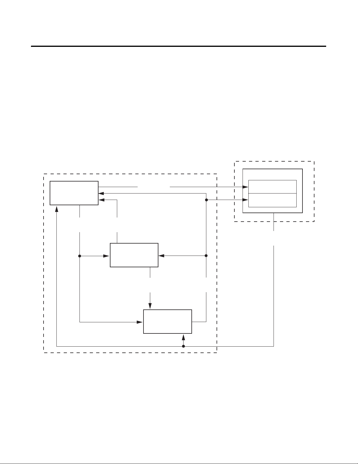
Chapter
Machine Module
Application
Modules
Device
Modules
Machine
Commands
Application
Status
Device
Commands
Device
Status
HMI Application
Controller Logic
Machine Faceplate
Device Faceplates
PanelView Plus Terminal
Operator
Commands
Machine Status
4
GuardLogix Configuration
In this chapter you will use RSLogix5000 to configure your GuardLogix controller, add and configure the
FANUC CNC AOP, import preconfigured logic modules, and edit them specifically for your application. In
addition, the logic modules include control, status, and diagnostic code that provide information to
preconfigured operator interface faceplates that you can run on personal computers or PanelView Plus terminals.
Figure 8 - Logic Modules
The machine module provides a state machine model that coordinates multiple devices and application logic for
coordinated CNC applications. It provides overall machine commands, for example start, stop, abort, clear, and
reset to the application modules and the individual device modules based on the status of the applications and
devices.
The application modules execute the machine commands and provide the more specific application commands
to the CNCs and devices. They also coordinate the machine and application status, and execute the application
fault commands. In addition, the toolkit includes control logic examples to help you create your specific
application logic.
Rockwell Automation Publication IASIMP-QS034A-EN-P - October 2012 81
Page 82

Chapter 4 GuardLogix Configuration
The device modules translate the uniform machine and application commands and provide uniform status and
diagnostics from the very specific device tags and parameters. This reduces much of the non-inventive code
required to control and monitor the many unique devices.
For more information on the machine, application, and device logic modules, refer to Appendix A.
To assist you in understanding how to best use the preconfigured logic files, the CNC Work Cell application is
used as an example in all of the logic configuration steps.
Table 3 - Preconfigured Logic Modules Used in CNC Work Cell Application
Module Type File Names
Machine Logic
Application Logic
Device Modules
Machine_Module
Device&Application_Status
Application_Module
App1_Gantry_Simulation
App2_CNC_Machining
Fanuc_CNC_Module
CIPMotion_Drive_Module
Before You Begin
• Complete your system architecture and hardware selection (refer to Chapter 1).
• Complete your system layout and wiring (refer to Chapter 2).
• Complete your FANUC CNC configuration (refer to Chapter 3).
What You Need
• The CNC Machining Accelerator Toolkit DVD, publication IASIMP-SP018. For a copy of the DVD,
contact your local Rockwell Automation distributor or sales representative.
• RSLogix 5000 software, version 20.0 or later
• RSLinx Classic software, version 2.56 or later
• If Rockwell Automation Kinetix or PowerFlex Drives are used in the system, the Drives and Motion
Accelerator Toolkit DVD, publication IASIMP-SP017
GuardLogix configuration and standard logic. For a copy of the DVD, contact your local Rockwell
Automation distributor or sales representative.
• If Rockwell Automation GuardLogix safety controller and safety components are used in the system, the
Safety Accelerator Toolkit DVD, publication SAFETY-CL002, can be used to significantly streamline
Guard I/O configuration and safety logic. For a copy of the DVD, contact your local Rockwell
Automation distributor or sales representative.
, can be used to significantly streamline
82 Rockwell Automation Publication IASIMP-QS034A-EN-P - October 2012
Page 83

GuardLogix Configuration Chapter 4
Start
No Yes
No Yes
Are you familiar with
the RSLogix 5000 software
programming environment,
motion instructions,
and programming
PowerFlex drives?
Are you using the
DMAT Wizard to configure
the initial GuardLogix controller
and Kinetix/PowerFlex drive
configuration and logic?
page 87
GuardLogix Controller and
Network Configuration
page 91
Import and Configure the
Machine Logic Module
page 100
Import and Configure CNC
Application Logic Module
Set Visible Rows for Equipment
Status Faceplate
page 84
Create an Initial GuardLogix Project
Using the DMAT Wizard
Import and Configure FANUC CNC
Device Logic Modules
page 126
Application Logic Creation Steps
That Use Application Logic Examples
page 136
Application Logic Creation Steps
That Use a Template
page 137
Verify and Save the Project File
page 95
FANUC CNC AOP
Configuration
Optional Step
Complete if Alarm
History faceplate is
used in application.
Optional Step
Complete if Equipment
Status faceplate is
used in application.
Safety Logic Integration
Set String Tag Names for
Alarm History Faceplate
Create Specific
Application Logic
Import and Configure Device
and Application Status Logic
page 104
page 108
page 111
page 113
page 120
page 146
Follow These Steps
Complete these steps to import and configure logic modules for your FANUC CNC application.
Rockwell Automation Publication IASIMP-QS034A-EN-P - October 2012 83
Page 84

Chapter 4 GuardLogix Configuration
Create an Initial GuardLogix Project Using the DMAT Wizard
If Rockwell Automation Kinetix or PowerFlex drives are used in the system, the DMAT Wizard can be used to
significantly streamline GuardLogix configuration and standard logic.
Order and Run the DMAT Wizard
1. Order a copy of the Drives and Motion Accelerator Toolkit DVD, publication IASIMP-SP017, from your
local Rockwell Automation distributor or sales representative.
2. Install the Drives and Motion Accelerator Toolkit onto your computer.
3. Run the DMAT Wizard following the instructions in Chapter 1 of the Drives and Motion Accelerator
Toolkit Quick Start, publication IASIMP-QS019.
a. When configuring project in the DMAT Wizard, be sure to select the GuardLogix controller within the
machine configuration if you are incorporating safety logic into the supervisory controller.
b. Configure all of the low voltage (PowerFlex) and servo (Kinetix) drives for your system.
c. You will be adding the FANUC CNC AOP and associated logic modules per the instructions later in
this chapter.
Import the Preconfigured RSLogix 5000 Project
Follow these steps to open the preconfigured RSLogix 5000 project.
1. Launch RSLogix 5000 software.
84 Rockwell Automation Publication IASIMP-QS034A-EN-P - October 2012
Page 85

2. Click the Open icon on the
toolbar.
3. From the Files of type
pull-down menu choose All
RSLogix 5000 files.
GuardLogix Configuration Chapter 4
4. Navigate to the RSLogix
5000 XML file that was created by the
DMAT Wizard and Click Open.
If the Drives and Motion Accelerator Toolkit was installed in the default directory, you will find the
RSLogix 5000 XML file in:
C:\Documents and Settings\PC Name\My Documents\DMAT\ProjectName\MachineName.
Rockwell Automation Publication IASIMP-QS034A-EN-P - October 2012 85
Page 86

Chapter 4 GuardLogix Configuration
IMPORTANT
For the CNC Work Cell example, the path is:
C:\Documents and Settings\PCName\My Documents\DMAT\CNC_Work_Cell\CNC_Work_Cell.
5. From the Revision pull-down menu, choose
the version of RSLogix 5000 software to
import into.
Your RSLogix 5000 software must be version 20.0 or later to use the FANUC CNC AOP.
6. Click Import to save and open the project
as an ACD file.
After the import process is complete, the
project opens and the controller organizer
displays all of the preconfigured project
components including the controller,
network, device configurations, the
preconfigured logic program files and the
faceplate and control AOI files.
Because the DMAT Wizard created a
project with a controller, network
module, and Machine Module logic, go to
FANUC CNC AOP Configuration on
page 95.
86 Rockwell Automation Publication IASIMP-QS034A-EN-P - October 2012
Page 87

GuardLogix Configuration Chapter 4
IMPORTANT
GuardLogix Controller and Network Configuration
In this section you will create a new GuardLogix project file and configure the EtherNet/IP communications.
Create a New Project File
Throughout this section the controller and network configuration procedures are written specifically for a
1756-L6x or 1756-L6xS ControlLogix controller. If you are integrating Kinetix motion into your project, we
recommend that you select a 1756-L7xS for your system. Steps for other Logix controller and communication
modules are similar.
If you are creating a new project and have not configured your personal computer communication or controller hardware,
see Appendix D
1. From the Start menu, launch RSLogix 5000 software.
.
2. Click New Project.
The New Controller dialog box
opens.
Rockwell Automation Publication IASIMP-QS034A-EN-P - October 2012 87
Page 88

Chapter 4 GuardLogix Configuration
3. Configure the new controller.
a. From the Type pull-down menu,
choose the controller type.
b. From the Revision pull-down
menu, choose the revision.
c. Type the file name in the Name
field.
d. From the Chassis Type pull-down
menu, choose the chassis.
e. Enter the Logix processor slot
(leftmost slot = 0).
4. Click OK.
5. From the Edit menu, choose
Controller Properties.
The Controller Properties dialog
box opens.
6. Click the Date/Time tab.
7. Check Enable Time
Synchronization.
This enables time
synchronization for the
controller.
8. Click OK.
88 Rockwell Automation Publication IASIMP-QS034A-EN-P - October 2012
Page 89

GuardLogix Configuration Chapter 4
TIP
Configure Ethernet Module for your HMI Terminal and CNC Modules
1. Expand I/O Configuration in the Controller
Organizer.
2. Right-click I/O Configuration and choose New
Module.
The Select Module Type dialog box opens.
3. Expand the Communications
category and select your 1756-series
Ethernet module.
For systems communicating to a
FANUC CNC over an EtherNet/IP
network, a 1756-EN2x or
1756-EN3x module is required.
In this example, the 1756-EN2TR
module is selected.
4. Click Create.
The New Module dialog box opens.
5. Configure the new module.
a. Enter the module Name.
b. Enter the Logix EtherNet/IP
module slot (leftmost slot = 0).
c. Select an Ethernet Address option.
In this example, the Private Network
address is selected.
d. Enter the address of your
EtherNet/IP module.
In this example, the last octet of the
address is 10.
6. Click Change in the Module
Definition area.
The Module Definition dialog box opens.
Rockwell Automation Publication IASIMP-QS034A-EN-P - October 2012 89
Page 90

Chapter 4 GuardLogix Configuration
IMPORTANT
IMPORTANT
7. From the Time Sync Connection
pull-down menu, choose Time Sync and
Motion.
Time Sync functionality is what
enables motion control on an
Ethernet network. While not
specifically required for the CNC
communication, without this
setting, you won’t be able to run
motion applications.
8. Click OK to close the Module
Definition dialog box.
9. Click Yes when prompted to confirm
your module definition changes.
10. Click OK to close the New Module
dialog box.
Your new module appears under the
I/O Configuration folder in the Controller Organizer.
For the CNC Work Cell application example, the
1756-EN2TR Ethernet module is the only communication
module that is needed. However, if your application
requires other communication modules, such as sercos
communication, for Kinetix drives, refer to the Drives and
Motion Accelerator Toolkit, publication IASIMP-QS019
.
Save the Project File
When you configured the ControlLogix controller you named your (.acd) application file. In this example, the
file name is CNC_Work_Cell. Before closing RSLogix 5000 software, save your file.
Click to save your RSLogix 5000 application
file.
90 Rockwell Automation Publication IASIMP-QS034A-EN-P - October 2012
Page 91
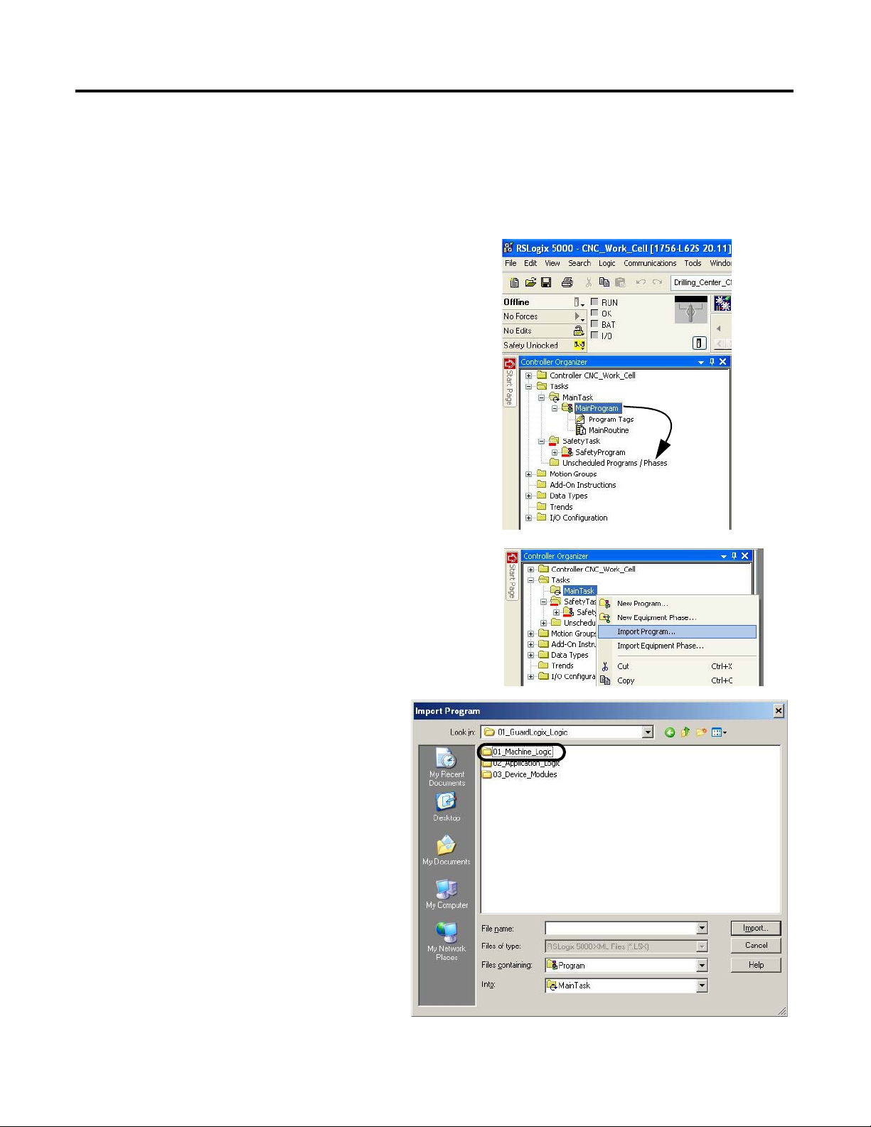
GuardLogix Configuration Chapter 4
Import and Configure the Machine Logic Module
In this example, you add the preconfigured machine logic program file to your RSLogix5000 project and
configure it to your specific application.
1. Open your RSLogix 5000 software project that you
created in the previous section.
For the CNC Work Cell application example, the
CNC_Work_Cell project was opened.
2. Expand the Tasks folder in your Controller Organizer and
drag-and-drop the MainProgram folder to the
Unscheduled Programs / Phases folder.
3. Right-click the Main Task folder, and choose Import
Program.
4. Navigate to the 01_GuardLogix_Logic
folder within the toolkit’s files folder and
open the 01_Machine_Logic folder.
The file path is C:\Program
Files\RA_Simplification\CMAT\A-Files\
4-Controller Logic\01_GuardLogix_Logic.
Rockwell Automation Publication IASIMP-QS034A-EN-P - October 2012 91
Page 92
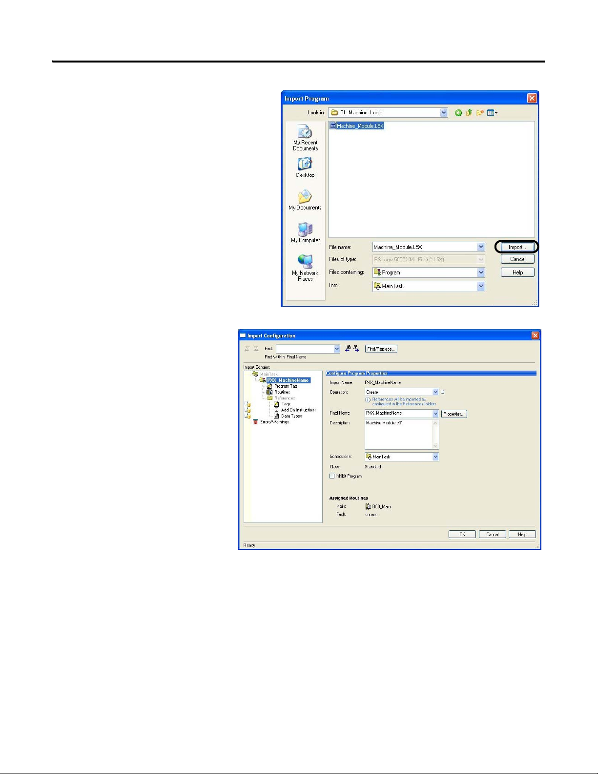
Chapter 4 GuardLogix Configuration
5. Select the Machine_Module.L5x file and
click Import.
The Import Configuration dialog
box opens.
92 Rockwell Automation Publication IASIMP-QS034A-EN-P - October 2012
Page 93

6. Type the desired name for your
machine in the Final Name field.
For the CNC Work Cell
application example,
P01_CNC_Work_Cell is the
Final Name.
7. Click Tags in the Import
Content organizer.
The Configure Tag References dialog box opens.
GuardLogix Configuration Chapter 4
8. Replace _MachineName with the desired tag name of your machine.
Rockwell Automation Publication IASIMP-QS034A-EN-P - October 2012 93
Page 94

Chapter 4 GuardLogix Configuration
For the CNC Work Cell application example, CNC_Work_Cell is the tag name.
9. Click OK.
The new machine program appears in the Controller Organizer
within the Main Task folder.
94 Rockwell Automation Publication IASIMP-QS034A-EN-P - October 2012
Page 95

GuardLogix Configuration Chapter 4
IMPORTANT
FANUC CNC AOP Configuration
To configure the FANUC AOP you update the CNC add-on profiles (AOP), and add and configure the
FANUC CNC.
Update FANUC CNC Add-On Profile (AOP)
The FANUC CNC add-on profiles are independent of RSLogix 5000 software releases. Update your CNC add-on profiles to
make sure your application runs correctly.
Add-on profiles (AOP) are available for download at the RSLogix 5000 Add-On Profiles website:
http://support.rockwellautomation.com/controlflash/LogixProfiler.asp.
1. Log in to the RSLogix 5000 Add-On Profiles website,
http://support.rockwellautomation.com/controlflash/LogixProfiler.asp.
The RSLogix 5000 Add-On
Profiles dialog box opens.
2. Find the FANUC CNC profile.
3. Click the Add-On Profile icon and
follow the download instructions.
4. Extract the AOP zip file and run
setup.
Rockwell Automation Publication IASIMP-QS034A-EN-P - October 2012 95
Page 96

Chapter 4 GuardLogix Configuration
Add and Configure FANUC CNC
For this CNC Work Cell application example, you will add the FANUC CNC to the EtherNet I/P network.
1. Open your RSLogix 5000 software project file.
2. Expand the I/O
Configuration folder in the
Controller Organizer and
browse to the controller
backplane.
3. Right-click the network
communication module for
your CNC and choose New
Module.
For the CNC Work Cell
example, the 1756-EN2TR
module is selected.
The Select Module Type
dialog box opens.
4. Click the FANUC
Corporation vendor and
select the appropriate CNC
series module.
For the CNC Work Cell
example, the FANUC
CNC module type is
selected for the Drill CNC.
5. Click Create.
The New Module dialog
box opens.
96 Rockwell Automation Publication IASIMP-QS034A-EN-P - October 2012
Page 97

6. Configure the new module.
a. Type the module Name.
b. Select an Ethernet Address
option.
In this example, the Private
Network address is
selected.
7. In the Module Definition
field click Change.
The Module Definition
dialog box opens.
8. Configure module
definitions.
GuardLogix Configuration Chapter 4
The Module Definition
dialog box lets you configure
and access CNC data beyond
standard I/O.
a. Enter the series letter
appropriate for your CNC
hardware.
b. Enter major and minor
revisions appropriate for
your CNC hardware.
c. Enter number of
allocations to use and
allocation number,
according to appropriate
configuration of CNC.
Rockwell Automation Publication IASIMP-QS034A-EN-P - October 2012 97
Page 98

Chapter 4 GuardLogix Configuration
d. Set the IO Size for your CNC
communication.
For the CNC Work Cell application
example, the IO Size (bytes) is set to
256 bytes.
e. Click OK to close the Module
Definition dialog box.
f. Click Yes to accept the
changes.
98 Rockwell Automation Publication IASIMP-QS034A-EN-P - October 2012
Page 99

9. Click OK to close the New
IMPORTANT
Module dialog box.
10. Repeat the previous process
for all other CNC modules
needed for your application.
GuardLogix Configuration Chapter 4
For the CNC Work Cell application example, two CNC
modules are needed, one for drilling, and one for machining.
The added modules appear in the I/O configuration tree, as
shown here.
The CNC Work Cell application example includes two
CNC modules and two gantry drives, as shown here.
However, if your application involves additional
devices/modules, such as Kinetix drives, refer to the
Drives and Motion Accelerator Toolkit, publication
IASIMP-QS019
.
Save the Project File
When you have added and configured each of the CNC modules that are to be used in your application, save the
project.
Click to save your RSLogix 5000 application
file.
Rockwell Automation Publication IASIMP-QS034A-EN-P - October 2012 99
Page 100
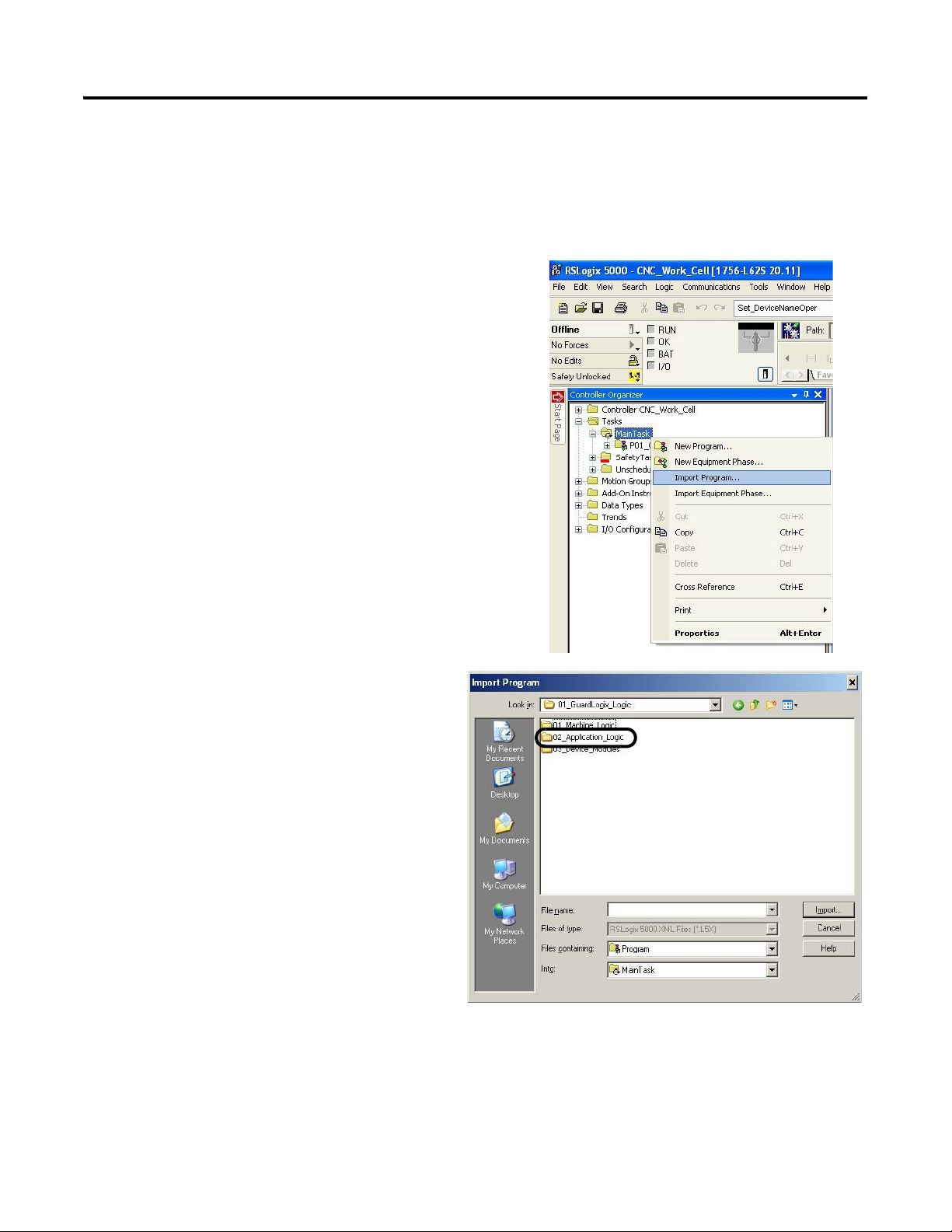
Chapter 4 GuardLogix Configuration
Import and Configure CNC Application Logic Module
In this example, you add preconfigured application logic to your RSLogix 5000 project and configure it for each
of your CNC applications within your machine.
1. Expand the Tasks folder in your Controller Organizer, and
right-click the Main Task folder.
2. Choose Import Program.
3. Navigate to the 01_GuardLogix_Logic folder
within the toolkit’s files folder and open the
02_Application Logic folder.
The file path is C:\Program
Files\RA_Simplification\CMAT\A-Files\
4-Controller Logic\01_GuardLogix_Logic.
100 Rockwell Automation Publication IASIMP-QS034A-EN-P - October 2012
 Loading...