

Page 1

Installation Instructions
English 1
Deutsch 11
Français 21
Español 31
Italiano 41
Passive Isolator, 1 Channel
931H-A1A1N-IP
Read these instructions before using the product and retain for future information.
10000043423
DIR 10000043423
(Version 00)
Page 2

1. General instructions
• Disconnect power prior to installation
• Installation only by Qualified personnel
• Follow all applicable local and national
electrical codes
Appropriate safety measures against
electrostatic discharge (ESD) should be
taken during assembly and adjustment.
WARNINGWARNING
2
Page 3

2. Application
931H-A1A1N-IP can be used for the galvanic
isolation of standard 0(4) ... 20 mA signals.
They are supplied by the measured signal and
require no additional auxiliary supply.
The measured signal is transmitted in a ratio of 1:1.
3. Mounting
931H-A1A1N-IP can be mounted on standard
TS 35 rails.
Refer to the following sections for individual
mounting steps.
3
Page 4
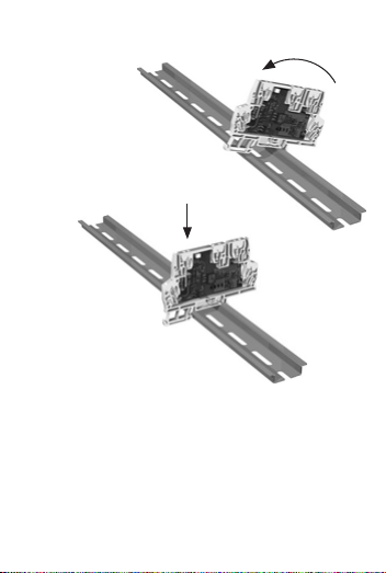
3.1 Mounting on standard rail TS 35
4
1.
2.
Page 5

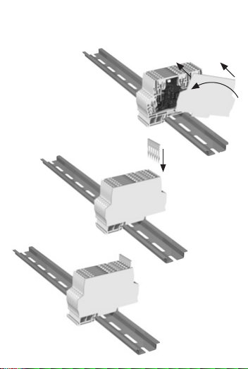
3.2
Mounting of end plate and plug-in jumper
5
1.
2.
3.
Page 6
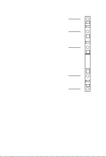
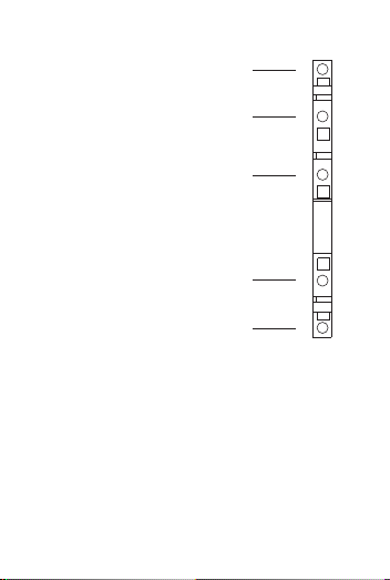
4. Electrical connection
Output +
0 ... 20 mA
Output –
Not connected
Input –
0 ... 20 mA
Input +
4.1 Equipment
A screwdriver with a width of up to 3 mm is required
to connect the wires to the tension clamp terminals.
6
5
4
3
2
1
Page 7
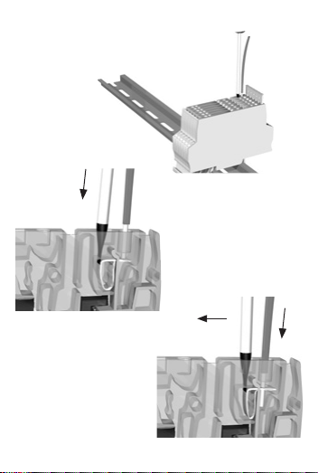
4.2 Wiring
7
1.
2.
3.
Page 8

4.3 Connection data
Wire strip length 8 mm ± 0.5
Wire cross sections
solid 0.5 ... 2.5 mm
2
stranded 0.5 ... 2.5 mm
2
with wire-end ferrule 0.5 ... 1.5 mm
2
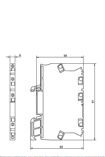
5. Dimensions
8
Page 9

6. Technical Data
Input 0 ... 20 mA
Input voltage max. 15 V
Operating current < 100 μA
Voltage drop 2.5 ... 3 V (at 20 mA)
Input overload capacity max. 50 mA, 15 V
Output 0 ... 20 mA, max. 10 V
Load 500 Ω
Response time approx. 5 ms for a load of 500 Ω
(to reach 99% program value)
Residual ripple < 10 mV
eff
General data
Chopper frequency approx. 200 kHz
Transmission errors < 0.1 % of end value + 0.05 % of
measured value / 100 Ω load
Temperature effect
1)
50 ppm/K from measured value
for a load of 0 Ω
Test voltage
Input / output 510 V AC, 50 Hz
EMC
2)
EMC directive
EN 61 326
EN 61 326/A1
Ambient temperature
Operation -25 °C ... +60 °C
Storage -40 °C ... +85 °C
1) Medium temperature coefficient in the specified
operating temperature range (-25 °C ... +60 °C)
2) Valid for 4 ... 20 mA; minor deviations are possible
during interferences.
9
Page 10

7. Ordering Data
Accessories
End Barrier 931H-EB1
Plug-In Jumper
Plug-In Jumper, 2-pole, yellow 1492-CJLJ6-2
Plug-In Jumper, 3-pole, yellow 1492-CJLJ6-3
Plug-In Jumper, 4-pole, yellow 1492-CJLJ6-4
Plug-In Jumper, 5-pole, yellow 1492-CJLJ6-5
Plug-In Jumper, 6-pole, yellow 1492-CJLJ6-6
Plug-In Jumper, 7-pole, yellow 1492-CJLJ6-7
Plug-In Jumper, 8-pole, yellow 1492-CJLJ6-8
Plug-In Jumper, 9-pole, yellow 1492-CJLJ6-9
Plug-In Jumper, 10-pole, yellow 1492-CJLJ6-10
10
DIR 10000043423
(Version 00)
Page 11

11
Lesen Sie diese Beipackinformation bevor Sie das Produkt installieren und heben
Sie diese für weitere Informationen auf.
Beipackinformation
Analog Messwandler
931H-A1A1N-IP
Page 12

1. Allgemeine Hinweise
Bei der Installation ist auf Schutzmaßnahmen gegen elektrostatische
Entladung (ESD) zu achten.
Nicht die offene Schaltung berühren!
ACHTUNGACHTUNG
12
Page 13

2. Anwendung
Der 931H-A1A1N-IP dient zur galvanischen
Trennung von Normsignalen 0(4) ... 20 mA.
Er versorgt sich aus dem Messsignal und benötigt
keine weitere Hilfsenergie.
Die Übertragung des Messsignals erfolgt im
Verhältnis 1:1.
3. Montage
Der 931H-A1A1N-IP wird auf TS 35 Normschienen
aufgerastet.
Die Montage ist in den folgenden Abschnitten
beschrieben.
13
Page 14

3.1 Aufrasten auf Normschiene TS 35
14
1.
2.
Page 15
3.2 Montage der Abschlussplatte und der
Querverbindungen
15
1.
2.
3.
Page 16

4. Der elektrische Anschluss
Ausgang +
0 ... 20 mA
Ausgang –
nicht belegt
Eingang –
0 ... 20 mA
Eingang +
4.1 Hilfsmittel
Zum Anschluss der Leitungen an die Zugfederklemmen wird z.B. ein Schraubendreher mit einer
Breite von bis zu 3 mm benötigt.
16
5
4
3
2
1
Page 17

4.2 Leitungen anschließen
17
1.
2.
3.
Page 18

4.3 Anschlussdaten
Abisolierlänge 8 mm ± 0,5
Leiterquerschnitte
eindrähtig 0,5 ... 2,5 mm
2
feindrähtig 0,5 ... 2,5 mm
2
mit Aderendhülse 0,5 ... 1,5 mm
2
5. Abmessungen
18
Page 19

6. Technische Daten
Eingang 0 ... 20 mA
Eingangsspannung max. 15 V
Ansprechstrom < 100 μA
Spannungsabfall 2,5 ... 3 V (bei 20 mA)
Überlastbarkeit am Eingang max. 50 mA, 15 V
Ausgang 0 ... 20 mA, max. 10 V
Bürde 500 Ω
Reaktionzeit
(wenn der ca. 5 ms bei 500 Ω Bürde
Ausgangswert 99% erreicht)
Restwelligkeit < 10 mV
eff
Allgemeine Daten
Chopperfrequenz ca. 200 kHz
Übertragungsfehler < 0,1 % vom Endwert +
0,05 % vom Messwert /
100 Ω Bürde
Temperatureinfluss
1)
50 ppm/K vom Messwert bei
0 Ω Bürde
Prüfspannung
Eingang / Ausgang 510 V AC, 50 Hz
EMV
2)
EMVG
EN 61 326
EN 61 326/A1
Umgebungstemperatur
Betrieb -25 °C ... +60 °C
Lagerung -40 °C ... +85 °C
1) Mittlerer Temperaturkoeffizient im spezifizierten
Betriebstemperaturbereich -25 °C ... + 60 °C
2) Gilt für 4 ... 20 mA; während der Störeinwirkung sind
geringe Abweichungen möglich.
19
Page 20

7. Bestelldaten
Zubehör
Abschlussplatte 931H-EB1
Querverbindung
Plug-In Jumper, 2-polig, gelb 1492-CJLJ6-2
Plug-In Jumper, 3-polig, gelb 1492-CJLJ6-3
Plug-In Jumper, 4-polig, gelb 1492-CJLJ6-4
Plug-In Jumper, 5-polig, gelb 1492-CJLJ6-5
Plug-In Jumper, 6-polig, gelb 1492-CJLJ6-6
Plug-In Jumper, 7-polig, gelb 1492-CJLJ6-7
Plug-In Jumper, 8-polig, gelb 1492-CJLJ6-8
Plug-In Jumper, 9-polig, gelb 1492-CJLJ6-9
Plug-In Jumper, 10-polig, gelb 1492-CJLJ6-10
20
DIR 10000043423
(Version 00)
Page 21

21
Lisez cette notice d’utilisation avant d’installer le produit et gardez cette fiche
pour obtenir des informations additionelles.
Notice d’utilisation
Convertisseur analogique
931H-A1A1N-IP
Page 22

1. Indications générales
Lors de l’installation, il est nécessaire de
considérer des précautions contre
décharges électrostatiques.
Ne pas toucher le câblage ouvert!
ATTENTIONATTENTION
22
Page 23

2. Utilisation
Le 931H-A1A1N-IP est utilisé pour l’isolation
galvanique des signaux standard 0(4) ... 20 mA.
Il est alimenté par le signal mesuré et n’est pas
besoin de l’énergie auxiliaire supplémentaire.
La transmission du signal mesuré est réalisée à
raison de 1:1.
3. Montage
Les 931H-A1A1N-IP peuvent aussi bien être montés
sur des rails de norme DIN TS 35.
Le montage est décrit aux sections suivantes.
23
Page 24

3.1 Encliquetage sur rail de norme TS 35
24
1.
2.
Page 25

3.2 Montage de la plaque de fermeture et de la
connexion transversale
25
1.
2.
3.
Page 26

4. Raccordement électrique
Sortie +
0 ... 20 mA
Sortie –
Non occupé
Entrée –
0 ... 20 mA
Entrée +
4.1 Accessoires
Pour raccorder les conducteurs aux bornes à
ressort de traction on peut utiliser un tournevis avec
une étendue jusqu’à 3 mm.
26
5
4
3
2
1
Page 27

4.2 Raccordement de conducteurs
27
1.
2.
3.
Page 28
4.3 Données de connexion
Longueur dénudée 8 mm ± 0,5
Sections de conducteur
unifilaire 0,5 ... 2,5 mm
2
à fils de faible diamètre 0,5 ... 2,5 mm
2
avec embout de protection 0,5 ... 1,5 mm
2
5. Dimensions
28
Page 29

6. Données techniques
Entrée 0 ... 20 mA
Tension d’entrée max. 15 V
Courant actif < 100 μA
Chute de tension 2,5 ... 3 V (à 20 mA)
Capacité de surcharge à l’entrée max. 50 mA, 15 V
Sortie 0 ... 20 mA , max. 10 V
Charge 500 Ω
Temps de réponse
(Pour atteindre
approximatif 5 ms pour
99% de la valeur programmée) une charge de 500 Ω
Ondulation résiduelle < 10 mV
eff
Données générales
Fréquence de vibreur env. 200 kHz
Erreur de transmission < 0,1 % de la valeur finale
+ 0,05 % de la valeur
mesurée / 100 Ω charge
Effet de température
1)
50 ppm/K de la valeur
mesurée à 0 Ω charge
Tension d’essai
Entrée/ sortie 510 V CA, 50 Hz
CEM
2)
directive CEM
EN 61 326
EN 61 326/A1
Température ambiante
Température de fonctionnement -25 °C ... +60 °C
Temperature de stockage -40 °C ... +85 °C
1) Coefficient de température moyen à la gamme de
température spécifiée -25 °C ... +60 °C
2) Valable pour 4 ... 20 mA; faibles déviations
peuvent se produire lors des perturbations.
29
Page 30

7. Référence
Accessoires
Plaque de fermeture 931H-EB1
Connexion transversale
Plug-In Jumper, 2-polaire, jaune 1492-CJLJ6-2
Plug-In Jumper, 3-polaire, jaune 1492-CJLJ6-3
Plug-In Jumper, 4-polaire, jaune 1492-CJLJ6-4
Plug-In Jumper, 5-polaire, jaune 1492-CJLJ6-5
Plug-In Jumper, 6-polaire, jaune 1492-CJLJ6-6
Plug-In Jumper, 7-polaire, jaune 1492-CJLJ6-7
Plug-In Jumper, 8-polaire, jaune 1492-CJLJ6-8
Plug-In Jumper, 9-polaire, jaune 1492-CJLJ6-9
Plug-In Jumper, 10-polaire, jaune 1492-CJLJ6-10
30
DIR 10000043423
(Version 00)
Page 31

31
Lea la presente información antes de instalar el producto y consérvela para
informaciones adicionales.
Hoja adicional
Convertidor análogo
931H-A1A1N-IP
Page 32

1. Indicaciones generales
Durante la instalación se tiene que
fijarse en las medidas protectoras
contra descarga electroestática (ESD).
¡No toque la conexión abierta!
¡ATENCI¡ATENCIÓNÓN!
32
Page 33

2. Aplicación
El 931H-A1A1N-IP sirve a la separación galvánica
de señales de norma 0(4) ... 20 mA. Se alimenta de
la señal de medida y no necesita energía auxiliar
ulterior.
La transmisión de la señal de medida se efectúa con
la relación 1:1.
3. Montaje
El 931H-A1A1N-IP puede instalarse encima de las
subbases estandarizadas TS 35.
El montaje se descibe en los párrafos siguientes.
33
Page 34

3.1
Montaje sobre subbases estandarizadas TS 35
34
1.
2.
Page 35

3.2 Montaje de la placa terminal y de las
conexiones transversales
35
1.
2.
3.
Page 36
4. La conexión eléctrica
Salida +
0 ... 20 mA
Salida –
No ocupada
Entrada –
0 ... 20 mA
Entrada +
4.1 Accesorios
Para la conexión de las líneas con los bornes de
muelles de tracción se mecesita por ejemplo un
destornillador con una largura hasta 3 mm.
36
5
4
3
2
1
Page 37

4.2 Conexión de las líneas
37
1.
2.
3.
Page 38

4.3 Datos de conexión
Largura de aislamiento 8 mm ± 0,5
Diámetros de conductor
de un hilo 0,5 ... 2,5 mm
2
de hilo fino 0,5 ... 2,5 mm
2
con terminal tubular 0,5 ... 1,5 mm
2
5. Dimensiones
38
Page 39

6. Datos técnicos
Entrada 0 ... 20 mA
Voltaje de entrada máx. 15 V
Corriente de reacción < 100 μA
Caída de voltaje 2,5 ... 3 V (a 20 mA)
Sobrecargabilidad en la entrada máx. 50 mA, 15 V
Salida 0 ... 20 mA, máx. 10 V
Carga 500 Ω
Tiempo de respuesta
(para
aprox. de 5 ms para una
conseguir el 99% del valor programado)
carga de 500 Ω
Ondulación residual < 10 mV
eff
Datos generales
Frecuencia de Chopper ca. 200 kHz
Errores de transmisión < 0,1 % del valor final +
0,05 % del valor de
medida / carga de 100 Ω
Influencia por la temperatura
1)
50 ppm/K del valor de
medida con carga de 0 Ω
Voltaje de prueba
Entrada / salida 510 V AC, 50 Hz
CEM
2)
Ley CEM
EN 61 326
EN 61 326/A1
Temperatura ambiental
Temperatura servicio -25 °C ... +60 °C
Almacenamiento -40 °C ... +85 °C
1) Coeficiente mediano de temperatura en la gama de
servicio especificada -25 °C ... +60 °C
2) Válido para 4 ... 20 mA; durante la interferencia
divergencias menores son posible.
39
Page 40

7. Datos para el pedido
Accesorios
Placa terminal 931H-EB1
Conexión transversal
Plug-In Jumper, bipolar, amarillo 1492-CJLJ6-2
Plug-In Jumper, tripolar, amarillo 1492-CJLJ6-3
Plug-In Jumper, 4-polar, amarillo 1492-CJLJ6-4
Plug-In Jumper, 5-polar, amarillo 1492-CJLJ6-5
Plug-In Jumper, 6-polar, amarillo 1492-CJLJ6-6
Plug-In Jumper, 7-polar, amarillo 1492-CJLJ6-7
Plug-In Jumper, 8-polar, amarillo 1492-CJLJ6-8
Plug-In Jumper, 9-polar, amarillo 1492-CJLJ6-9
Plug-In Jumper, 10-polar, amarillo 1492-CJLJ6-10
40
DIR 10000043423
(Version 00)
Page 41

41
Prima di installare il modulo leggere attentamente le istruzioni contenute in
questo manuale.
Istruzioni per l’uso
Convertitore analogico
931H-A1A1N-IP
Page 42

1. Note generali
Durante l’installazione si deve badare
alle misure protettive contro la scarica
elettrostatica (ESD).
Non toccare il collegamento aperto!
ATTENZIONEATTENZIONE
42
Page 43

2. Impiego
Il 931H-A1A1N-IP serve alla separazione galvanica
di segnali di norma 0(4) ... 20 mA. Si alimenta dal
segnale di misurazione e non necessita energia
ausiliare ulteriore.
La trasmissione del segnale di misurazione si
effettua nella relazione 1:1.
3. Montaggio
Il 931H-A1A1N-IP può essere montato su guide di
supporto TS 35.
Il montaggio viene descritto nei brani seguenti.
43
Page 44

3.1 Montaggio su guide di norma TS 35
44
1.
2.
Page 45

3.2 Montaggio della piastra terminale e dei
collegamenti trasversali
45
1.
2.
3.
Page 46

4. Collegamento elettrico
Uscita +
0 ... 20 mA
Uscita –
Non occupata
Ingresso –
0 ... 20 mA
Ingresso +
4.1 Aiuti
Per il collegamento dei cavi con i morsetti di molle di
trazione si necessita per esempio un cacciavite da
larghezza fino a 3 mm.
46
5
4
3
2
1
Page 47

4.2 Collegamento dei cavi
47
1.
2.
3.
Page 48

4.3 Dati di collegamento
Lunghezza di spellaggio 8 mm ± 0,5
Diametri di conduttore
da un filo 0,5 ... 2,5 mm
2
da filo fine 0,5 ... 2,5 mm
2
con terminale 0,5 ... 1,5 mm
2
5. Dimensioni
48
Page 49

6. Dati tecnici
Ingresso 0 ... 20 mA
Ingresso in tensione mass. 15 V
Corrente di reazione < 100 μA
Calo di tensione 2,5 ... 3 V (con 20 mA)
Sovraccaricabilità all’ingresso mass. 50 mA, 15 V
Uscita 0 ... 20 mA, mass. 10 V
Carico 500 Ω
Tempo di risposta
(per
circa 5 ms con carico di 500 Ω
raggiungere il 99% del valore programmato)
Ondulazione residuale < 10 mV
eff
Dati generali
Frequenza di chopper ca. 200 kHz
Errore di trasmissione < 0,1 % del valore finale +
0,05 % del valore di
misurazione / carico 100 Ω
Influenza dalla temperatura
1)
50 ppm/K del valore di
misurazione con carico di 0 Ω
Tensione di prova
Ingresso / uscita 510 V AC, 50 Hz
CEM
2)
Legge CEM
EN 61 326
EN 61 326/A1
Temperatura ambientale
Temperatura di esercizio -25 °C ... +60 °C
Magazzinaggio -40 °C ... +85 °C
1) coefficiente di temperatura mediano nella gamma della
temperatura di esercizio specificata -25 °C ... +60 °C
2) valido per 4 ... 20 mA; durante il disturbo sono possibili
divergenze minori.
49
Page 50

7. Dati per l’ordinazione
Accessori
Piastra terminale 931H-EB1
Collegamento trasversale
Plug-In Jumper, bipolare, giallo 1492-CJLJ6-2
Plug-In Jumper, tripolare, giallo 1492-CJLJ6-3
Plug-In Jumper, 4-polare, giallo 1492-CJLJ6-4
Plug-In Jumper, 5-polare, giallo 1492-CJLJ6-5
Plug-In Jumper, 6-polare, giallo 1492-CJLJ6-6
Plug-In Jumper, 7-polare, giallo 1492-CJLJ6-7
Plug-In Jumper, 8-polare, giallo 1492-CJLJ6-8
Plug-In Jumper, 9-polare, giallo 1492-CJLJ6-9
Plug-In Jumper, 10-polare, giallo 1492-CJLJ6-10
50
Page 51

51
Page 52

DIR 10000043423
(Version 00)
Page 53

53
Page 54

54
 Loading...