

Page 1
Installation Instructions
Ethernet Network Appliance (with Network
Address Translation)
Catalog Number 9300-ENA
Topic Page
Important User Information 2
North American Hazardous Location Approval 3
European Hazardous Location Approval 4
Preventing Electrostatic Discharge 6
Install the Modules 8
DIN Rail Mounting 8
Panel Mounting 10
Wire the Module 11
Attach the Power Connector 14
Connect the Copper Ethernet Ports 14
Grounding Considerations 14
Use the Module 15
Using the SD Card 18
Additional Resources 23
Page 2
2 Ethernet Network Appliance (with Network Address Translation)
Publication
9300-IN001A-EN-P - December 2012
Important User Information
Solid state equipment has operational characteristics differing from those of electromechanical
equipment. Safety Guidelines for the Application, Installation and Maintenance of Solid State Controls
(Publication
SGI-1.1 available from your local Rockwell Automation sales office or online at
http://literature.rockwellautomation.com
) describes some important differences between solid state
equipment and hard-wired electromechanical devices. Because of this difference, and also because of
the wide variety of uses for solid state equipment, all persons responsible for applying this equipment
must satisfy themselves that each intended application of this equipment is acceptable.
In no event will Rockwell Automation, Inc. be responsible or liable for indirect or consequential damages
resulting from the use or application of this equipment.
The examples and diagrams in this manual are included solely for illustrative purposes. Because of the
many variables and requirements associated with any particular installation, Rockwell Automation, Inc.
cannot assume responsibility or liability for actual use based on the examples and diagrams.
No patent liability is assumed by Rockwell Automation, Inc. with respect to use of information, circuits,
equipment, or software described in this manual.
Reproduction of the contents of this manual, in whole or in part, without written permission of Rockwell
Automation, Inc., is prohibited.
Throughout this manual, when necessary, we use notes to make you aware of safety considerations.
WARNING
Identifies information about practices or circumstances that can cause an explosion in
a hazardous environment, which may lead to personal injury or death, property
damage, or economic loss.
IMPORTANT
Identifies information that is critical for successful application and understanding of
the product.
ATTENTION
Identifies information about practices or circumstances that can lead to personal
injury or death, property damage, or economic loss. Attentions help you identify a
hazard, avoid a hazard, and recognize the consequences.
Labels may be on or inside the equipment (for example, drive or motor) to alert people
that dangerous voltage may be present.
Labels may be on or inside the equipment (for example, a drive or motor) to alert
people that surfaces may reach dangerous temperatures.
SHOCK HAZARD
BURN HAZARD
Page 3
Ethernet Network Appliance (with Network Address Translation) 3
Publication
9300-IN001A-EN-P - December 2012
North American Hazardous Location Approval
The following information applies when
operating this equipment in hazardous
locations.
Informations sur l’utilisation de cet
équipement en environnements dangereux.
Products marked "CL I, DIV 2, GP A, B, C, D" are suitable for
use in Class I Division 2 Groups A, B, C, D, Hazardous
Locations and nonhazardous locations only. Each product is
supplied with markings on the rating name plate indicating
the hazardous location temperature code. When
combining products within a system, the most adverse
temperature code (lowest "T" number) may be used to help
determine the overall temperature code of the system.
Combinations of equipment in your system are subject to
investigation by the local Authority H aving Jurisdiction at
the time of installation.
Les produits marqués "CL I, DIV 2, GP A, B, C, D" ne
conviennent qu'à une utilisation en environnements de
Classe I Division 2 Groupes A, B, C, D dangereux et non
dangereux. Chaque produit est livré avec des marquages sur
sa plaque d'identification qui ind iquent le code de
température pour les environnement s dangereux. Lorsque
plusieurs produits sont combinés dans un système, le code de
température le plus défavorable (code de t empérature le plus
faible) peut être utilisé pour déterminer le code de
température global du système. Les combinaisons
d'équipements dans le système sont sujettes à inspection par
les autorités locales qualifiées au moment de l'installation.
WARNING
EXPLOSION HAZARD -
• Do not disconnect equipme nt unless
power has been removed or the
area is known to be nonhazardous.
• Do not disconnect connections to
this equipment unless power has
been removed or the area is known
to be nonhazardous. Secure any
external connections that mate to
this equipment by using screws,
sliding latches, threaded
connectors, or other means
provided with this product.
• Substitution of components may
impair suitability for Class I,
Division 2.
• If this product contains batteries,
they must only be changed in an
area known to be nonhazardous.
AVERTISSEMENT
RISQUE D’EXPLOSION –
• Couper le courant ou s'assurer
que l'environnement est classé
non dangereux avant de
débrancher l'équipement.
• Couper le courant ou s'assurer
que l'environnement est classé
non dangereux avant de
débrancher les connecteurs. Fixer
tous les connecteurs externes
reliés à cet équipement à l'aide
de vis, loquets coulissants,
connecteurs filetés ou autres
moyens fournis avec ce produit.
• La substitution de composants
peut rendre cet équipement
inadapté à une utilisation en
environnement de Classe I,
Division 2.
• S'assurer que l'environnement est
classé non dangereux avant de
changer les piles.
Page 4
4 Ethernet Network Appliance (with Network Address Translation)
Publication
9300-IN001A-EN-P - December 2012
European Hazardous Location Approval
ATTENTION
This equipment is intended for use in potentially explosive atmospheres as
defined by European Union Directive 94/9/EC and has been found to comply
with the Essential Health and Safety Requirements relating to the design and
construction of Category 3 equipment intended for use in potentially explosive
atmospheres, given in Annex II to this Directive.
Compliance with the Essential Health and Safety Requirements has been
assured by compliance with EN 60079-15 and EN 60079-0.
WARNING
• This equipment is not resistant to sunlight or other sources of UV
radiation.
• This equipment must be installed in an enclosure providing at least IP54
protection when applied in Zone 2 environments.
• This equipment shall be used within its specified ratings defined by
Rockwell Automation.
• Provision shall be made to prevent the rated voltage from being exceeded
by transient disturbances of more than 40% when applied in Zone 2
environments.
• Secure any external connections that mate to this equipment by using
screws, sliding latches, threaded connectors, or other means provided
with this product.
• Do not disconnect equipment unless power has been removed or the area
is known to be nonhazardous.
Page 5

Ethernet Network Appliance (with Network Address Translation) 5
Publication
9300-IN001A-EN-P - December 2012
Environment and Enclosure
ATTENTION
This equipment is intended for use in a Pollution Degree 2 industrial
environment, in overvoltage Category II applications (as defined in IEC
publication 60664-1), at altitudes up to 2000 m (6562 ft) without derating.
This equipment is considered Group 1, Class A industrial equipment according
to IEC/CISPR Publication 11. Without appropriate precautions, there may be
potential difficulties ensuring electromagnetic compatibility in other
environments due to conducted as well as radiated disturbance.
This equipment is supplied as open-type equipment. It must be mounted within
an enclosure that is suitably designed for those specific environmental
conditions that will be present and appropriately designed to prevent personal
injury resulting from accessibility to live parts. The enclosure must have
suitable flame-retardant properties to prevent or minimize the spread of flame,
complying with a flame spread rating of 5VA, V2, V1, V0 (or equivalent) if
non-metallic. The interior of the enclosure must be accessible only by the use
of a tool. Subsequent sections of this publication may contain additional
information regarding specific enclosure type ratings that are required to
comply with certain product safety certifications.
In addition to this publication, see the following publications:
• Industrial Automation Wiring and Grounding Guidelines, publication
1770-4.1
, for additional installation requirements
• NEMA Standards publication 250, and IEC publication 60529, as
applicable, for explanations of the degrees of protection provided by
different types of enclosures
Page 6
6 Ethernet Network Appliance (with Network Address Translation)
Publication
9300-IN001A-EN-P - December 2012
Preventing Electrostatic Discharge
ATTENTION
This equipment is sensitive to electrostatic discharge, which can cause
internal damage and affect normal operation. Follow these guidelines
when you handle this equipment:
• Touch a grounded object to discharge potential static.
• Wear an approved grounding wriststrap.
• Do not touch connectors or pins on component boards.
• Do not touch circuit components inside the equipment.
• Use a static-safe workstation, if available.
• Store the equipment in appropriate static-safe packaging when
not in use.
ATTENTION
To comply with the CE Low Voltage Directive (LVD), all connections ot this
equipment must be powered from a source compliant with the following:
Safety Extra Low Voltage (SELV) or Protected Extra Low Voltage (PELV).
ATTENTION
To comply with UL restrictions, all connections to this equipment must be
powered from a source compliant with the following: Class 2.
Page 7
Ethernet Network Appliance (with Network Address Translation) 7
Publication
9300-IN001A-EN-P - December 2012
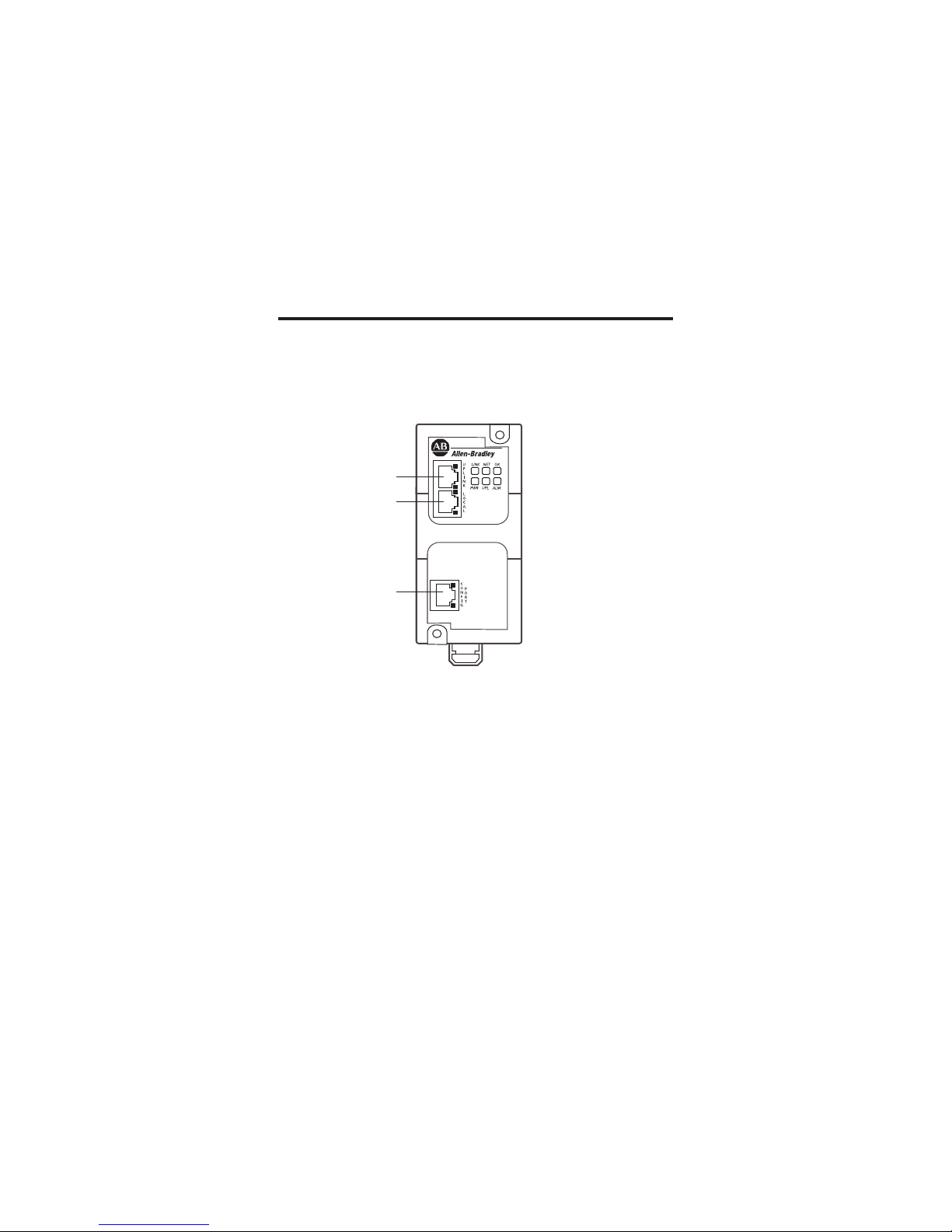
The figure shows Ethernet port identification for the 9300-ENA.
Ethernet Port Identification
31871-M
Local
Configuration
Port
Uplink
Page 8
8 Ethernet Network Appliance (with Network Address Translation)
Publication
9300-IN001A-EN-P - December 2012
Install the Modules
Mount the modules, as shown, in the vertical position only. We do not
recommend horizontal mounting due to thermal considerations. When
mounting, provide 50 mm (2 in.) of space on all sides for adequate heat
dissipation.
DIN Rail Mounting
Read this section for information on how to install and remove a module
using DIN rail mounting.
Install the Module
To install the module on DIN rail, proceed as follows.
1. Mount your DIN rail.
2. Snap the DIN-rail latch into the closed position.
IMPORTANT
Use care with the plastic DIN rail clip.
WARNING
If you connect or disconnect the communication cable with power applied to
this module or any device on the network, an electrical arc can occur. This
could cause an explosion in hazardous location installations.
Be sure that power is removed or the area is nonhazardous before proceeding.
WARNING
If you connect or disconnect wiring while the field-side power is on, an
electrical arc can occur. This could cause an explosion in hazardous location
installations. Be sure that power is removed or the area is nonhazardous
before proceeding.
Page 9

Ethernet Network Appliance (with Network Address Translation) 9
Publication
9300-IN001A-EN-P - December 2012
3. Hook the top slot over the DIN rail and push the module into
position on the DIN rail.
Remove the Module
To remove the module from DIN rail, proceed as follows.
1. Place a screwdriver in the DIN-rail latch at the bottom of the module.
2. Hold the module and pry downward on the latch until the module is
released from the DIN rail.
31873-M
31874-M
Page 10

10 Ethernet Network Appliance (with Network Address Translation)
Publication
9300-IN001A-EN-P - December 2012
Panel Mounting
Provide 15 mm (0.6 in.) clearance for DIN-rail latch movement during
installation and removal. Dimensions in the figure are in mm (in.). These
views are not actual size.
107
(4.21)
118
(4.64)
88.9
(3.50)
27.7
(1.09)
52.07
(2.05)
27.7
(1.09)
3216-M
Page 11

Ethernet Network Appliance (with Network Address Translation) 11
Publication
9300-IN001A-EN-P - December 2012
Wire the Module
Read this section for information about external power supply wiring.
Provide low voltage DC power to the module by using the screw terminals
contained in the power connector.
32317-M
GND
DC-
DC+
Bottom View
Side View
SD Card Slot
Power
Connector
Screw Terminals
Power
receptacle
Page 12

12 Ethernet Network Appliance (with Network Address Translation)
Publication
9300-IN001A-EN-P - December 2012
Follow these steps to prepare the DC power cable.
1. Locate the power connector.
2. Identify the positive and return DC power connections on the
connector.
The positive DC power connection is labeled DC+ and the negative
DC power connection in the adjacent connection labeled DC-.
3. Measure a length of 0.82...0.52 mm
2
(18...20 AWG) copper wire long
enough to connect to the DC power source.
4. Using an 18-gauge wire-stripping tool, strip each of the two wires to
6.3 mm (0.25 in.) ±0.5 mm (0.02 in.).
Do not strip more than 6.8 mm (0.27 in.) of insulation from the wire.
Stripping more than the recommended amount of wire can leave
exposed wire from the connector after installation.
32322-M
GND
DC-
DC+
0.5 inch (12.7 mm)
31789-M
Page 13

Ethernet Network Appliance (with Network Address Translation) 13
Publication
9300-IN001A-EN-P - December 2012
5. Insert the exposed part of the positive wire into the connection
labeled DC+ and the exposed part of the return wire into the
connection labeled DC-.
Make sure that you cannot see any wire lead. Only wire with insulation
should extend from the connector.
6. Use a ratcheting-torque screwdriver to torque the power and relay
connector captive screws (above the installed wire leads) to 0.23 N•m
(2.0 lb in.).
7. Connect the other end of the positive wire (the one connected to
DC+) to the positive terminal on the DC power source, and connect
the other end of the return wire (the one connected to DC-) to the
return terminal on the DC power source.
Page 14

14 Ethernet Network Appliance (with Network Address Translation)
Publication
9300-IN001A-EN-P - December 2012
Attach the Power Connector
Follow these steps to connect the DC power connector:
1. Insert the power connector into the Power receptacle on the bottom
of the unit.
2. Use a screwdriver to tighten the captive screws on the sides of the
power connector.
Connect the Copper Ethernet Ports
Follow these steps to connect the copper Ethernet port(s) on the module.
1. Locate the copper Ethernet RJ-45 ports on the module.
2. Connect one end of an Ethernet cable to one of the copper ports on
the module.
3. Connect the other end of the Ethernet cable to a device in your
Ethernet network.
Grounding Considerations
This product is intended to be mounted to a well-grounded mounting surface
such as a metal panel. The functional earth ground connection to the product
is through the specified pin on the dc connection terminals.
Refer to publication 1770-4.1
, Industrial Automation Wiring and Grounding
Guidelines, for additional information.
ATTENTION
You must provide an acceptable grounding path for each device in your
application. For more information on proper grounding guidelines, refer to
publication 1770-4.1
, Industrial Automation Wiring and Grounding Guidelines.
IMPORTANT
The ground connection is required at the grounding pin on the dc connection
terminals
Page 15

Ethernet Network Appliance (with Network Address Translation) 15
Publication
9300-IN001A-EN-P - December 2012
Use the Module
To start using your module, follow this procedure. For information about the
status indicators on the module, refer to the LED functions on page 17.
1. Connect the 9300-ENA module’s configuration port to your
computer’s LAN card by using an Ethernet patch cable or cross-over
cable and follow these steps.
a. Choose Start>Settings>Network Connections and right-click
Local Area Connection and Properties.
b. From the Local Area Connection Properties menu, check
Ethernet Protocol (TCP/IP), and click Properties.
Page 16

16 Ethernet Network Appliance (with Network Address Translation)
Publication
9300-IN001A-EN-P - December 2012
c. From the Ethernet Protocol (TCP/IP) Properties menu, change
the IP address to 192.168.1.3 and Subnet mask to 255.255.255.0.
2. Connect to the module via a Web browser by using these steps.
a. Open a browser window.
b. Enter the default IP address of 192.168.1.1 in the address bar,
press Enter, and note the following defaults:
• Username should be left blank.
• Password is PASSWORD.
Page 17

Ethernet Network Appliance (with Network Address Translation) 17
Publication
9300-IN001A-EN-P - December 2012
3. Configure the module; you can get complete configuration
instructions by clicking the Help tabs to view the embedded manual.
9300-ENA Status Indicators Layout
Reference this chart for status indicator functions when the module is in use.
Indicator Status Description
OK Flashing green/red Booting (or selftest)
OK Flashing green Device operational (heart beat)
OK Steady red Unrecoverable fault
NET Steady green Cable is plugged in and an IP address is configured on
configuration port
LINK Steady green SD card connected (not implemented at this time)
UPL Steady green Uploading new firmware, uploading new configuration
ALM Flashing red Error/alarm code indication
Page 18

18 Ethernet Network Appliance (with Network Address Translation)
Publication
9300-IN001A-EN-P - December 2012
Using the SD Card
The 9300-ENA ships without an SD card installed. Complete these steps to
install/remove the SD card from the 9300-ENA.
1. Verify that the SD card is not in use by checking to be sure the SD
indicator is off.
a. Verify that the SD card is locked or unlocked according to your
preference.
ATTENTION
SD slot is for maintenance only and power must be disconnected or the area
known to be free of ignitable concentrations of flammable gases or vapors
when SD slot is used for maintenance.
WARNING
When you insert or remove the Secure Digital (SD) memory card while power
is on, an electrical arc can occur. This could cause an explosion in hazardous
location installations.
Be sure that power is removed or the area is nonhazardous before proceeding.
IMPORTANT
• Verify that the SD card status indicator is off and that the card is not in
use before removing it.
• We recommend that you do the following:
- Use the SD cards available from Rockwell Automation (catalog number
1784-SD1 or 1784-SD2).
• While other SD cards may be used with the controller, Rockwell
Automation has not tested the use of those cards with the controller. If
you use a SD card other than those available from Rockwell Automation,
you may experience data corruption or loss.
• Also, SD cards not provided by Rockwell Automation do not have the
same industrial, environmental, and certification ratings as those
available from Rockwell Automation.
Locked
Unlocked
Page 19

Ethernet Network Appliance (with Network Address Translation) 19
Publication
9300-IN001A-EN-P - December 2012
2. Locate the SD card slot on the bottom of the unit.
3. Insert the SD card until it latches.
4. To remove, press and release the SD card to eject it.
Specifications
Technical Specifications
Attribute 9300-ENA
Power requirements 12…48V DC
Class 2/SELV
250 mA @ 24V D
Power dissipation, max 5.8 W @ 60 °C (140 °F)
Thermal dissipation 24.6 BTU/hr @ 60 °C (140 °F) max
Network ports 3 RJ-45 10/100 full/half duplex ports
Protocols TCP/IP, EtherNet/IP, Http, DHCP, Bootp, FTP
Indicators 6 port indicators,
6 status indicators
EtherNet/IP features Link status, connections active
Module features DHCP client, Bootp client
Voltage variation IEC 61000-4-29:
10 ms interruption on DC supply ports
Enclosure type rating Meets IP20
Inrush current, max 2.2 A
SD Card Slot
Page 20

20 Ethernet Network Appliance (with Network Address Translation)
Publication
9300-IN001A-EN-P - December 2012
Isolation voltage
50V (continuous), Basic Insulation Type
No isolation between individual Ethernet ports
Routine tested at 707V AC for 1 s, DC power ports to
ground and DC power ports to Ethernet ports
Wire size Ethernet connections:
RJ45 connector according to IEC 60603-7, 2 or 4 pair
Category 5e min cable according to TIA 568-B.1 or
Category 5 cable according to ISO/IEC 24702
DC Power connections:
0.33... 3.3 mm
2
(22...12 AWG) solid or stranded copper wire
rated at 75 °C (167 °F) or greater, 1.2 mm (3/64 in.)
insulation max
Functional Ground connection:
3.3 mm
2
(12 AWG) solid or stranded copper wire rated at
75 °C (167 °F) or greater
Torque DC power and functional ground: 1.36 N•m (12 lb•in)
Wiring category
(1) (2)
2 - on DC power ports
2 - on Ethernet ports
North American temp code T4
IEC temp code T3
(1)
Use this Conductor Category information for planning conductor routing. Refer to Industrial
Automation Wiring and Grounding Guidelines, publication 1770-4.1
.
(2)
Use this Conductor Category information for planning conductor routing as described in the
appropriate system level installation manual.
Technical Specifications
Attribute 9300-ENA
Page 21

Ethernet Network Appliance (with Network Address Translation) 21
Publication
9300-IN001A-EN-P - December 2012
Environmental Specifications
Attribute 9300-ENA
Emissions CISPR 11: Group 1, Class A
Temperature, operating IEC 60068-2-1 (Test Ad, Operating Cold),
IEC 60068-2-2 (Test Bd, Operating Dry Heat),
IEC 60068-2-14 (Test Nb, Operating Thermal Shock):
0…60 °C (32…140 °F)
Temperature,
nonoperating
IEC 60068-2-1 (Test Ab, Unpackaged Non-operating Cold),
IEC 60068-2-2 (Test Bb, Unpackaged Non-operating Dry Heat),
IEC 60068-2-14 (Test Na, Unpackaged Non-operating Thermal
Shock):
-40…85 °C (-40…185 °F)
Relative humidity IEC 60068-2-30 (Test Db, Unpackaged Damp Heat):
5…95% noncondensing
Vibration IEC 60068-2-6 (Test Fc, Operating):
2 g @ 10…500 Hz
Operating shock IEC 60068-2-27 (Test Ea, Unpackaged Shock):
15 g
Nonoperating shock IEC 60068-2-27 (Test Ea, Unpackaged Shock):
30 g
ESD immunity IEC 61000-4-2:
6 kV contact discharges
8 kV air discharges
Radiated RF immunity IEC 61000-4-3:
10V/m with 1 kHz sine-wave 80% AM from 80…2000 MHz
10V/m with 200 Hz 50% Pulse 100% AM at 900 MHz
10V/m with 200 Hz 50% Pulse 100% AM at 1890 MHz
1V/m with 1 kHz sine-wave 80% AM from 2000…2700 MHz
EFT/B immunity IEC 61000-4-4:
±2 kV at 5 kHz on power ports
±1 kV at 5 kHz on Ethernet ports
Page 22

22 Ethernet Network Appliance (with Network Address Translation)
Publication
9300-IN001A-EN-P - December 2012
Surge transient immunity IEC 61000-4-5:
±1 kV line-line (DM) and ±2 kV line-earth CM) on DC power
ports
±2 kV line-earth (CM) on shielded Ethernet port
Conducted RF immunity IEC 61000-4-6:
10V rms with 1 kHz sine-wave 80% AM
from 150 kHz…80 MHz
Magnetic field immunity IEC 61000-4-8:
30 A/m long duration and 300 A/m short duration
at 50 and 60 Hz
Certifications
Certifications (when
product is marked)
(1)
Valu e
CE European Union 2004/108/EC EMC Directive, compliant with:
EN 61326-1; Meas./Control/Lab., Industrial Requirements
EN 61000-6-2; Industrial Immunity
EN 61000-6-4; Industrial Emissions
EN 61131-2; Programmable Controllers
(Clause 8, Zone A & B)
C-Tick Australian Radiocommunications Act, compliant with:
-AS/NZS CISPR11; Industrial Emissions
EtherNet/IP ODVA conformance tested to EtherNet/IP specifications
c-UL-us UL Listed Industrial Control Equipment, certified for US and
Canada. See UL File E356258.
UL Listed for Class I, Divison 2 Group A,B,C,D Hazardous
Locations, certified for US and Canada.
See UL Files E356259.
(1)
See the Product Certification link at http://www.ab.com for Declarations of Conformity,
Certificates, and other certification details.
Environmental Specifications
Attribute 9300-ENA
Page 23

Ethernet Network Appliance (with Network Address Translation) 23
Publication
9300-IN001A-EN-P - December 2012
Additional Resources
These documents contain additional information concerning related products
from Rockwell Automation.
You can view or download publications at
http://ra.rockwellautomation.com/literature. To order paper copies of
technical documentation, contact your local Allen-Bradley distributor or
Rockwell Automation sales representative.
Resource Description
EtherNet/IP Industrial Protocol White Paper,
publication ENET-WP001
Describes how to implement services and
data objects on a TCP/UDP/IP based
Ethernet network.
Industrial Automation Wiring and Grounding
Guidelines, publication 1770-4.1
Provides general guidelines for installing a
Rockwell Automation industrial system.
Product Certifications website,
http://www.ab.com
Provides declarations of conformity,
certificates, and other certification details.
Page 24

Rockwell Automation Support
Rockwell Automation provides technical information on the Web to assist you in using
its products. At http://www.rockwellautomation.com/support
, you can find technical
manuals, technical and application notes, sample code and links to software service
packs, and a MySupport feature that you can customize to make the best use of these
tools. You can also visit our Knowledgebase at
http://www.rockwellautomation.com/knowledgebase
for FAQs, technical infor mation,
support chat and forums, software updates, and to sign up for product notification
updates.
For an additional level of technical phone support for installation, configuration, and
troubleshooting, we offer TechConnect
SM
support programs. For more information,
contact your local distributor or Rockwell Automation representative, or visit
http://www.rockwellautomation.com/support/
.
Installation Assistance
If you experience a problem within the first 24 hours of installation, please review the
information that's contained in this manual. You can also contact a special Customer
Support number for initial help in getting your product up and running.
New Product Satisfaction Return
Rockwell Automation tests all of its products to ensure that they are fully operational
when shipped from the manufacturing facility. However, if your product is not
functioning and needs to be returned, follow these procedures.
Allen-Bradley, Rockwell Automation, Rockwell Software, and TechConnect are trademarks of
Rockwell Automation, Inc.
Trademarks not belonging to Rockwell Automation are property of their respective companies.
United States 1.440.646.3434
Outside United States Use the Worl dwid e Locat or
at
http://www.rockwellautomation.com/support/americas/phone_en.html
, or contact your
local Rockwell Automation representative.
United States Contact your distributor. You must provide a Customer Support case number
(see phone number above to obtain one) to your distributor in order to
complete the return process.
Outside United States Please contact your local Rockwell Automation representative for the return
procedure.
Publication 9300-IN001A-EN-P - December 2012
Copyright © 2012 Rockwell Automation, Inc. All rights reserved. Printed in the U.S.A.
Rockwell Otomasyon Ticaret A.Ş., Kar Plaza İş Merkezi E Blok Kat:6 34752 İçerenköy, İstanbul, Tel: +90 (216) 5698400
PN-171958
 Loading...