

Page 1
8720MC Regenerative
Power Supply
Installation Manual
Page 2

Page 3

Important User Information
Because of the variety of uses for the products described in this publication,
those responsible for the application and use of this control equipment must
satisfy themselves that all necessary steps have been taken to assure that each
application and use meets all performance and safety requirements, including
any applicable laws, regulations, codes and standards.
The illustrations, charts, sample programs and layout examples shown in this
guide are intended solely for purposes of example. Since there are many
variables and requirements associated with any particular installation,
Allen-Bradley does not assume responsibility or liability (to include
intellectual property liability) for actual use based upon the examples shown
in this publication.
Allen-Bradley publication SGI-1.1, Safety Guideline for the Application,
Installation and Maintenance of Solid-State Control (avialable from your
local Allen-Bradley office), describes some inportant differences between
solid-state equipment and electromechanical devices that should be taken
into consideration when applying products such as those described in this
publication.
Reproduction of the contents of this copyrighted publication, in whole or
part, without written permission of Rockwell Automation, is prohibited.
ATTENTION: Identifies information about practices
!
or circumstances that can lead to personal injury or death,
property damage, or economic loss.
Attention help you:
• identify a hazard
• avoid the hazard
• recognize the consequences
Important:
Identifies information that is especially important for successful
application and understanding of the product.
Page 4

European Communities (EC) Directive Compliance
If this product has the CE mark it is approved for installation within the
European Union and EEA regions. It has been designed and tested to meet
the following directives.
EMC Directive
This product is tested to meet the Council Directive 89/336/EC
Electromagnetic Compatibility (EMC) by applying the following standards,
in whole or in part, documented in a technical construction file:
• EN 50081-2 EMC - Generic Emission Standard, Part 2 Industrial Environment
• EN 50082-2-EMC - Generic Immunity Standard, Part 2 Industrial Environment
This product is intended for use in an industrial environment.
Low Voltage Directive
This product is tested to meet Council Directive 73/23/EEC Low Voltage, by
applying the safety requirements of EN 61131-2 Programmable Controllers,
Part 2 - Equipment Requirements and Tests. For specific information
required by EN 61131-2, see the appropriate sections in this publication, as
well as the Allen-Bradley pulbication Industrial Automation Wiring and
Grounding Guidelines For Noise Immunity, publication 1770-4.1.
This equipment is classified as open equipment and must be mounted in an
enclosure during operation to provide safety protection.
Page 5

Table of Contents
Contents of This
Manual
About 8720MC-RSP
Regenerative Power
Supply
Chapter 1
Introduction .................................................................................. 1-1
Finding Information ...................................................................... 1-1
Assumptions About the Audience................................................ 1-2
Notes on Handling the 8720MC-RPS Regenerative Power
Supply .......................................................................................... 1-3
Chapter 2
Model Numbers of the 8720MC-RPS Regenerative Power
Supply and its Accessories.......................................................... 2-1
Power Rating................................................................................ 2-2
Appearance of the 8720MC-RPS Regenerative Power Supply.. 2-2
Appearance of Model 8720MC-RPS027 and
8720MC-RPS065 ................................................................... 2-2
Appearance of Model 8720MC-RPS190................................ 2-4
Main Components and Locations ................................................ 2-5
Terminal Blocks on the Main Circuit ............................................ 2-10
Main Power Terminal Block (TB1) for Model 8720MC-
RPS027 and 8720MC-RPS065.............................................. 2-12
Control Power Terminal Block (TB2) for Model 8720MC-
RPS027 and 8720MC-RPS065.............................................. 2-12
Mainl Power Terminal Bar for Model 8720MC-RPS190 ........ 2-13
Control Power Terminal Block (TB2) and Control Terminal
Block (TB4) for Model 8720MC-RPS190 ............................... 2-13
Regulator Board ........................................................................... 2-14
Jumpers and Switches ........................................................... 2-15
Sequence Signal Terminal Block (TB3)................................. 2-17
Installation
Wiring
Chapter 3
Installation Site............................................................................. 3-1
Environmental Conditions to be Met ...................................... 3-1
Required Total Area ............................................................... 3-2
Recommended Air Flow Clearance ....................................... 3-7
Notes on Installation .................................................................... 3-7
Chapter 4
Recommended Wire Sizes .......................................................... 4-1
Recommended Wire Sizes for Power Wiring to the Main
Power Terminal Block (TB1) and the Main Power Terminal
Bars ........................................................................................ 4-2
Recommended Wire Sizes for Power Wiring to the Control
Power Terminal Block (TB2) and the Control Terminal
Block (TB4)............................................................................. 4-2
AC Input Power Wiring fot Model 8720MC-RPS027 and
8720MC-RPS065 ......................................................................... 4-3
When Model 8720MC-RPS027 or 8720MC-RPS065 is
operated in the Power Regeneration Mode only ................... 4-7
When Model 8720MC-RPS027 and 8720MC-RPS065 are
adapted to Capacitors having large capacity......................... 4-9
Installing Circuit Breaker ........................................................ 4-11
Page 6

ii
Table of Contents
Installing Main Magnetic Contactor........................................ 4-11
Installing Reactor.................................................................... 4-12
Installing Varistor.................................................................... 4-13
Installing Harmonic Filter........................................................ 4-14
Installing Input Fuses ............................................................. 4-14
Installing Line Filters .............................................................. 4-14
Bus Bar and Output Fuses..................................................... 4-15
AC Input Power Wiring for Model 8720MC-RPS190................... 4-16
When Model 8720MC-RPS190 is operated in the Power
Regeneration Mode only ........................................................ 4-22
When Model 8720MC-RPS190 is adapted to Capacitors
having large capacity ............................................................. 4-24
Installing Circuit Breaker - 8720MCRPS190.......................... 4-26
Installing ACL Unit (Reactor Assembly) - 8720MC-
RPS190 .................................................................................. 4-26
Installing Fuses - 8720MC-RPS190....................................... 4-27
Installing 8720MC-EF190-VB EMC Filter Unit....................... 4-28
Installing DC Bus Power Output Wiring - All RPS units .............. 4-29
Grounding the 8720MC-RPS Regenerative Power Supply......... 4-29
Wiring To Comply with EMC........................................................ 4-30
Sequence Signal Wiring............................................................... 4-32
Sequence Signal Wiring ......................................................... 4-32
Operation Timing of Sequence Control Signals .................... 4-33
Installing Ribbon Cables .............................................................. 4-36
Notes on Wiring............................................................................ 4-37
Start and Adjustment
Operation Panel
Parameters
Chapter 5
Checking before Powering up the 8720MC-RPS Regenerative
Power Supply .................................................................................. 5-1
Verifying the Installation ............................................................ 5-1
Verifying the Rating of the 8720MC-RPS Regenerative
Power Supply ............................................................................ 5-2
Verifying Wiring ......................................................................... 5-2
Powering up the 8720MC-RPS Regenerative Power Supply ........ 5-2
Operating the 8720MC-RPS Regenerative Power Supply............. 5-3
Chapter 6
Configuration of the Operation Panel ............................................. 6-1
Operation Modes............................................................................. 6-1
Monitor Mode............................................................................. 6-2
Program Mode........................................................................... 6-3
Display............................................................................................. 6-3
Keypad ............................................................................................ 6-4
Status LEDs .................................................................................... 6-5
Chapter 7
Parameter Types............................................................................. 7-1
Protecting Parameters with Password............................................ 7-3
Displaying and Changing Parameter Values.................................. 7-3
User Parameters ............................................................................. 7-3
Factory Parameters ........................................................................ 7-5
Page 7

Table of Contents
iii
Error Codes and
Warning Buzzer
Inspecting Trouble
and Recovering
Special Replacement
Parts
Outline Drawings of
the Peripheral Devices
Chapter 8
Contents of Error Codes and Recovering ...................................... 8-2
Accessing and Clearing the Entries in the Error Log ..................... 8-5
Recovering from Fatal Error ........................................................... 8-6
Warning Buzzer............................................................................... 8-6
Chapter 9
Safety Precautions .......................................................................... 9-1
Preliminary Review ......................................................................... 9-2
Troubleshooting Flow Charts.......................................................... 9-2
8720MC-RPS Regenerative Power Supply Does Not Run ...... 9-2
DC Bus Voltage Does Not Go Up ............................................. 9-3
Chapter 10
Chapter 11
Outline Drawings of the Reactors................................................... 11-1
Outline Drawing of the Varistors..................................................... 11-3
Outline Drawing of the Harmonic Filters......................................... 11-4
Outline Drawing of the Line Filters ................................................. 11-5
8720MC-EF190-VB EMC Filter Unit for Model 8720MC-RPS190BM
and 8720MC-RPS190BS ................................................................ 11-7
Technical Specifications
Default Parameter Settings
Control Block Diagram
Appendix A
Appendix B
Appendix C
Page 8

iv
Table of Contents
End of Table of Contents
Page 9

Contents of This Manual
Chapter
1
Introduction
Finding Information
The 8720MC-RPS Regenerative Power Supply Bidirectional
Converter is a sinusoidal PWM converter which can control
increase of DC bus voltage and perform continuous power
generation.
The 8720MC-RPS Regenerative Power Supply, therefore, can be
used as power supply unit for various drives and inverter units.
This instruction manual covers the 8720MC-RPS Regenerative
Power Supply for 380-460 VAC, and describes the hardware
and the start-up and programming procedure for the 8720MC-RPS
Regenerative Power Supply. Read and understand this manual
before proceeding.
All the following units are UL/C-UL listed:
8720MC-RPS027BM,
8720MC-RPS065BM and 8720MC-RPS065BS,
8720MC-RPS190BM and 8720MC-RPS190BS
Also, the Declaration of Conformity with the requirement for CE
Mark was already issued for all the units.
The 8720MC-RPS Regenerative Power Supply is a bidirectional
converter with the following features:
• Use of chopper type voltage increasing method with sinusoidal
pulse-width-modulated (PWM) waveform control.
• Programmable DC bus voltage.
• Continuous power regeneration.
• Attenuation of the higher order harmonics in the line current.
• Safety interlocks and protection.
This manual describes the details of the 8720MC-RPS Regenerative
Power Supply in order to provide the user with a complete
understanding of the installation, wiring, operation and adjustment
of the product. As an aid in finding information in this manual,
each chapter is briefly described below:
• Chapter 1: Contents of This Manual
Provides situation for acquiring UL Marks and CE
Marks for the 8720MC-RPS Regenerative Power
Supply and information on how this manual is
organized and where to find additional
information.
Page 10

1-2
Contents of This Manual
• Chapter 2: About 8720MC-RPS Regenerative Power Supply
Identifies components of the 8720MC-RPS
Regenerative Power Supply, shows their locations,
and describes the main components.
• Chapter 3: Installation
Describes how to mount the 8720MC-RPS
Regenerative Power Supply properly.
• Chapter 4: Wiring
Describes how to properly wire and connect the
8720MC-RPS Regenerative Power Supply.
• Chapter 5: Start and Adjustment
Provides information on how to perform a final
check before power is applied, and instructions on
basic operation.
• Chapter 6: Operation Panel
Describes the composition and contents of the
operation panel.
• Chapter 7: Parameters
Provides detailed description of each parameter.
• Chapter 8: Error Codes and Warning Buzzer
Describes contents of error codes and how to
correct problems.
• Chapter 9: Inspecting Trouble and Recovering
Describes how to inspect and troubleshoot the
8720MC-RPS Regenerative Power Supply.
• Chapter 10: Special Replacement Parts
Provides a list of required replacement parts.
• Chapter 11: Outline Drawings of the Peripheral Devices
Provides outline dimensions of converters,
reactors, varistors, harmonic filters and line filters.
• Appendix A: Technical Specifications
Lists specifications of the 8720MC-RPS
Regenerative Power Supply in table form.
• Appendix B: Default Parameter Settings
Provides the default values of the parameters in
table form.
• Appendix C: Control Block Diagram
Provides a control block diagram.
Assumptions About the Audience
This manual is intended for electrical personnel familiar with the
operation of this equipment and the hazards involved.
Page 11
Contents of This Manual
1-3
Notes on Handling the
8720MC-RPS Regenerative
Power Supply
The following three labels are put on the 8720MC-RPS
Regenerative Power Supply, advising the user of the notes on
handling the unit. Read and understand the contents before using
the unit.
!
PWR
CAUTION!
WHEN YOU APPL Y POWER
AGAIN, VERIFY THAT
THIS LAMP "PWR" IS
TURNED OFF.
ME-B6013
!
DANGER
RISK OF ELECTRICAL SHOCK. DISCONNECT INPUT
POWER BEFORE SERVICING EQUIPMENT.
ME-B6015
CAUTION !
THIS EQUIPMENT MUST BE MOUNTED IN A SUITABLE
UL RECOGNIZED ENCLOSURE OR NEMA ENCLOSURE.
USE COPPER 60/75 DEGREE C WIRE ONLY.
Page 12

1-4
Contents of This Manual
End of Chapter
Page 13

Chapter
About 8720MC-RPS Regenerative Power Supply
This chapter describes model numbers, major components, their
locations, and terminal blocks of 8720MC-RPS Regenerative Power
Supply.
2
Model Numbers of the 8720MCRPS Regenerative Power
Supply and its Accessories
For operation of the 8720MC-RPS Regenerative Power Supply, a
line reactor is required for each incoming phase as well as a
varistor, a harmonic filter and a contactor. The following figure
shows the model numbers of the 8720MC-RPS Regenerative Power
Supply and its accessories.
Regenerative Power Supply
8720MC-RPSxxxvm-opt
BASE CATALOG NUMBER - CONVERTER
REGENERATIVE POWER SUPPLY SIZE
027 = 27 amp
065 = 65 amp
190 = 190 amp
INPUT VOLTAGE
B = 380 TO 460 VAC
TYPE
M = master
S = slave
See Note 1
Note 1: Blank includes the 8720MC - RPS only as a spare part.
HV2 option includes the 8720MC - RPS as well as 8720MC-HF-B2 harmonic
filter and 8720MC-VA-B varistor. HV2 option, however, is applied only to
8720MC-RPS027 and 8720MC-RPS065.
Line Reactor
8720MC-LRxx-ayyyb
Inductance as % Voltage Drop
03 = 3%
05 = 5%
10 = 10%
14 = 14%
Enclosure
blank = open
A = NEMA type 1
Current Rating
032 = 32 Amp
048 = 48 Amp
062 = 60 Amp
070 = 80 Amp
100 = 100 Amp
Voltage
B = 380 to 460 VAC
Voltage
B2 = 380 to 460 VAC
Voltage
B = 380 to 460 VAC
Current Rating
190 = 190 Amp
Voltage
B = 380 to 460 VAC
Harmonic Filter
8720MC-HF-b
Varistor
8720MC-VA-b
EMC Filter Unit
8720MC-EFxxx-Vb
Page 14
2-2
REGENERATIVE POWER SUPPLY
MC
READY
FAULT
PROGRAM
kW
About 8720MC-RPS Regenerative Power Supply
Power Rating
Appearance of the 8720MCRPS Regenerative Power
Supply
Power rating of 8720MC-RPS Regenerative Power Supply depends
on the number of units connected in parallel as shown in the table
below. Up to three units can be connected.
Table 2.1
Kind, Connection and Power Ratings
Kind of Unit
15 kW
37 kW
Connection
Single Unit
Single Unit
Two paralleled units
Model Number
8720MC-RPS027BM x 1
8720MC-RPS065BM x 1
8720MC-RPS065BM +
Power Rating
15 kW
37 kW
75 kW
8720MC-RPS065BS x 1
Three paralleled units
8720MC-RPS065BM +
110 kW
8720MC-RPS065BS x 2
125 kW
Single Unit
Two paralleled units
8720MC-RPS190BM x 1
8720MC-RPS190BM +
125 kW
250 kW
8720MC-RPS190BS x 1
Three paralleled units
8720MC-RPS190BM +
375 kW
8720MC-RPS190BS x 2
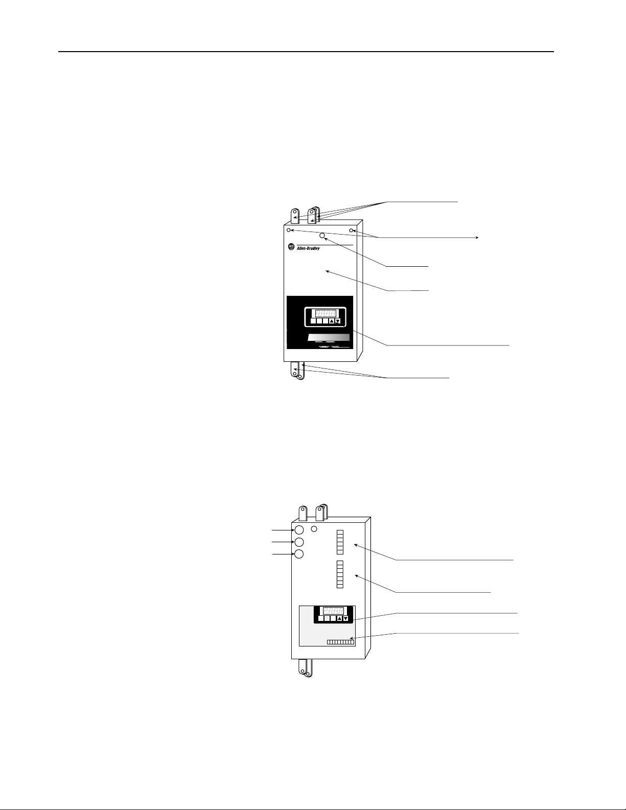
Appearance of Model 8720MC-RPS027 and 8720MC-RPS065
The figure below shows the front view of the 8720MC-RPS027 and
8720MC-RPS065 covered by the front cover.
The operation panel (only for master unit) and the power lamp can
be seen through the front cover. All the terminals blocks to
connect wiring are covered by the front cover.
Unit Front View
Hole for Cover Fixing Screw <1
Power Lamp
Front Cover
8720
READY
FAULT
PROGRAM
M
A
V
kW
ENT
PRG
RST
C
E
G
E
R
Y
L
P
P
S
U
R
W
E
P
O
IV
E
T
A
R
E
N
Operation Panel (only for Master Unit)
1> Model 8720MC-RPS027 has the cover fixing screw
at the right upper corner instead of the left upper corner.
Page 15
About 8720MC-RPS Regenerative Power Supply
READY
FAULT
PROGRAM
kW
POWER
Control Power Terminal Block (TB2)
Unit After Removing Regulator Board
When the front cover is removed from the 8720MC-RPS027 and
8720MC-RPS065 , the main power terminal block (TB1) and the
Regulator Board (only for master unit) will appear as shown in the
following figure. To remove the front cover, first remove the screw
at the upper left corner of the unit, and then lift up the cover. Note,
however, that Model 8720MC-RPS027 has the cover fixing screw
at the upper right corner instead of the upper left corner. Do not
drop the screw from the cover.
Unit After Removing Front Cover
POWER
Main Power Terminal Block (TB1)
READY
FAULT
PROGRAM
A
V
kW
ENT
PRG
RST
Regulator Board (only for Master Unit)
Sequence Signal Terminal Block (TB3)
2-3
The control power terminal block (TB2) for Model 8720MCRPS027 and 8720MC-RPS065 will be disclosed as shown in the
figure below, when the Regulator Board is opened to the left hand
side by removing the two fixing screws on the right hand side of the
bracket supporting the Regulator Board.
Page 16
2-4
REGENERATIVE POWER SUPPLY
8720
MC
About 8720MC-RPS Regenerative Power Supply
Appearance of Model 8720MC-RPS190
The figure below shows the front view of the 8720MC-RPS190
covered by the front cover.
This unit has the main power terminals L1 to L3 at the top of the
unit, and DC bus terminals P and N at the bottom of the unit.
L2
L3
L1
Main Power Terminals
Unit Front View
Hole for Cover Fixing Screw
Power Lamp
Front Cover
READY
FAULT
PROGRAM kW
M
8720
PN
A
V
ENT
PRG
RST
C
E
G
E
R
Y
L
P
P
S
U
R
W
E
P
O
IV
E
T
A
R
E
N
Operation Panel (only for Master Unit)
DC Bus Terminals
When the front cover is removed from the 8720MC-RPS190
Regenerative Power Supply, the Control Power Terminal Block
(TB2), the Control Terminal Block (TB4), the Regulator Board
(only for master unit) and Sequence Signal Terminal Block (TB3)
will appear as shown in the following figure.
Fuse1
Fuse2
Fuse3
READY
FAULT
PROGRAM kW
ENT
PRG
RST
L
L
L
PR1
PR2
PR3
+24V3
0V3
SENS
+24V2
0V2
MC1
MC2
Unit After Removing Front Cover
1AUX
2AUX
3AUX
Control Power Terminak Block (TB2)
Control Terminal Block (TB4)
A
V
Regulator Board (only for Master Unit)
Sequence Signal Terminal Block (TB3)
Page 17
About 8720MC-RPS Regenerative Power Supply
2-5
Main Components and Locations
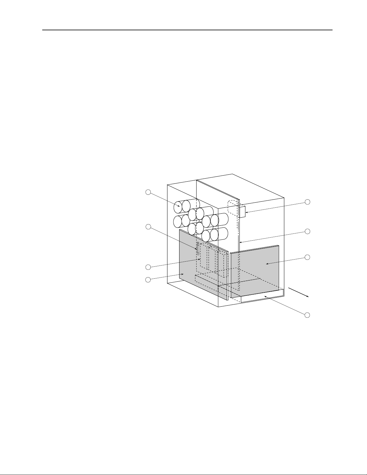
Model 8720MC-RPS027BM has the following main components.
The identification numbers provided correspond to the numbers
used in the following figure. The main components are included in
the special replacement part list shown in Chapter 10.
1. Regulator Board (BDSR) (only master unit has a Regulator
Board, not on slave unit)
2. Power Interface Board (PIFS)
3. Driver Board (RCPB)
4. Bus Capacitors
5. Cooling Fan
6. Power Modules
7. Fuse-1
8. Precharge/Discharge Resistor
The following figure shows the locations of the main components
of Model 8720MC2-RPS027BM.
4
8
7
6
2
3
1
Unit Front Side
5
Page 18
2-6
About 8720MC-RPS Regenerative Power Supply
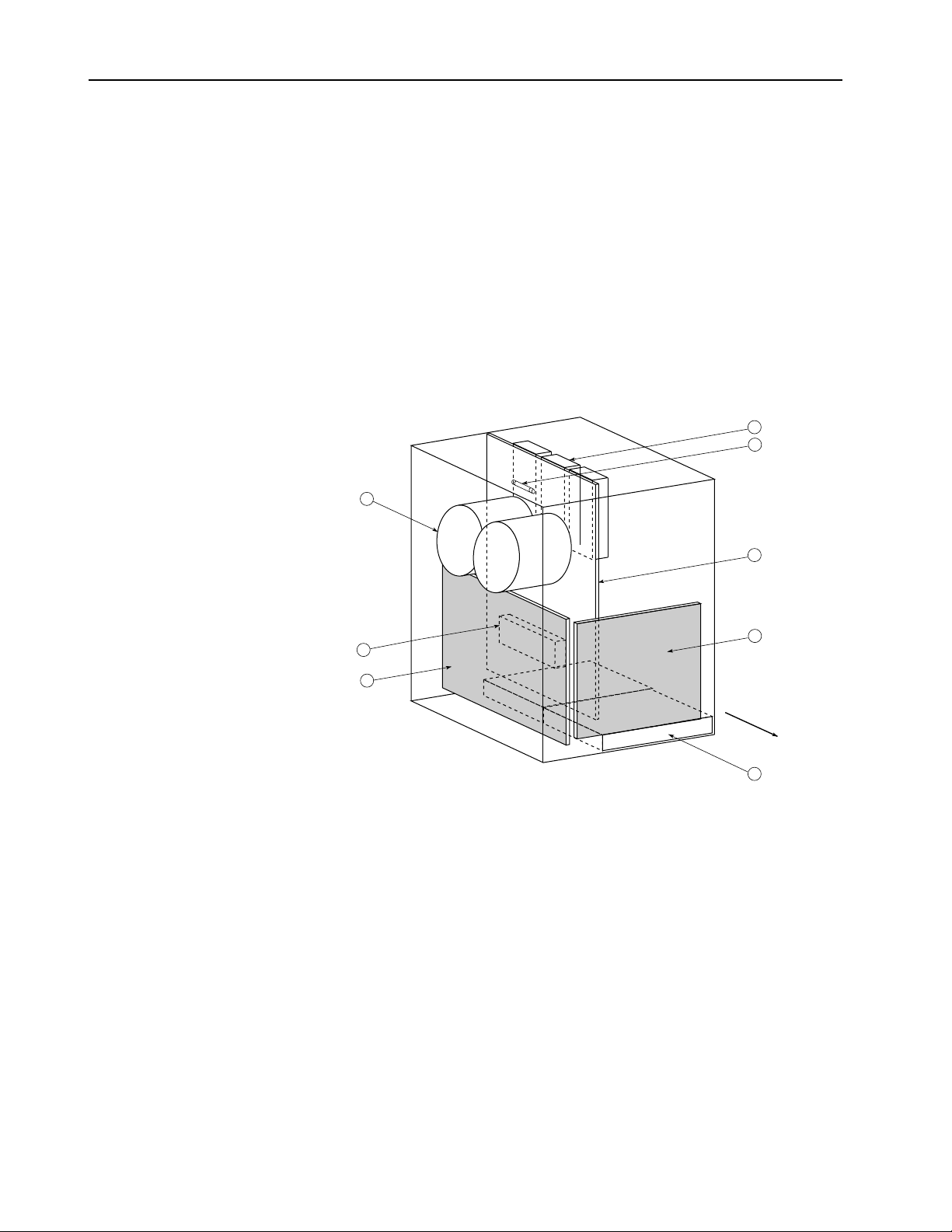
Model 8720MC-RPS065BM and 8720MC-RPS065BS have the
following main components.
1. Regulator Board (BDSR) (only master unit has a Regulator
Board, not on slave unit)
2. Power Interface Board (PIFS)
3. Driver Board (RCPB)
4. Bus Capacitors
5. Cooling Fan
6. Power Modules
7. Fuse-1
8. Precharge/Discharge Resistor
The following figure shows the locations of main components of
Model 8720MC-RPS065BM and 8720MC-RPS065BS.
6
7
4
3
8
2
1
Unit Front Side
5
Page 19
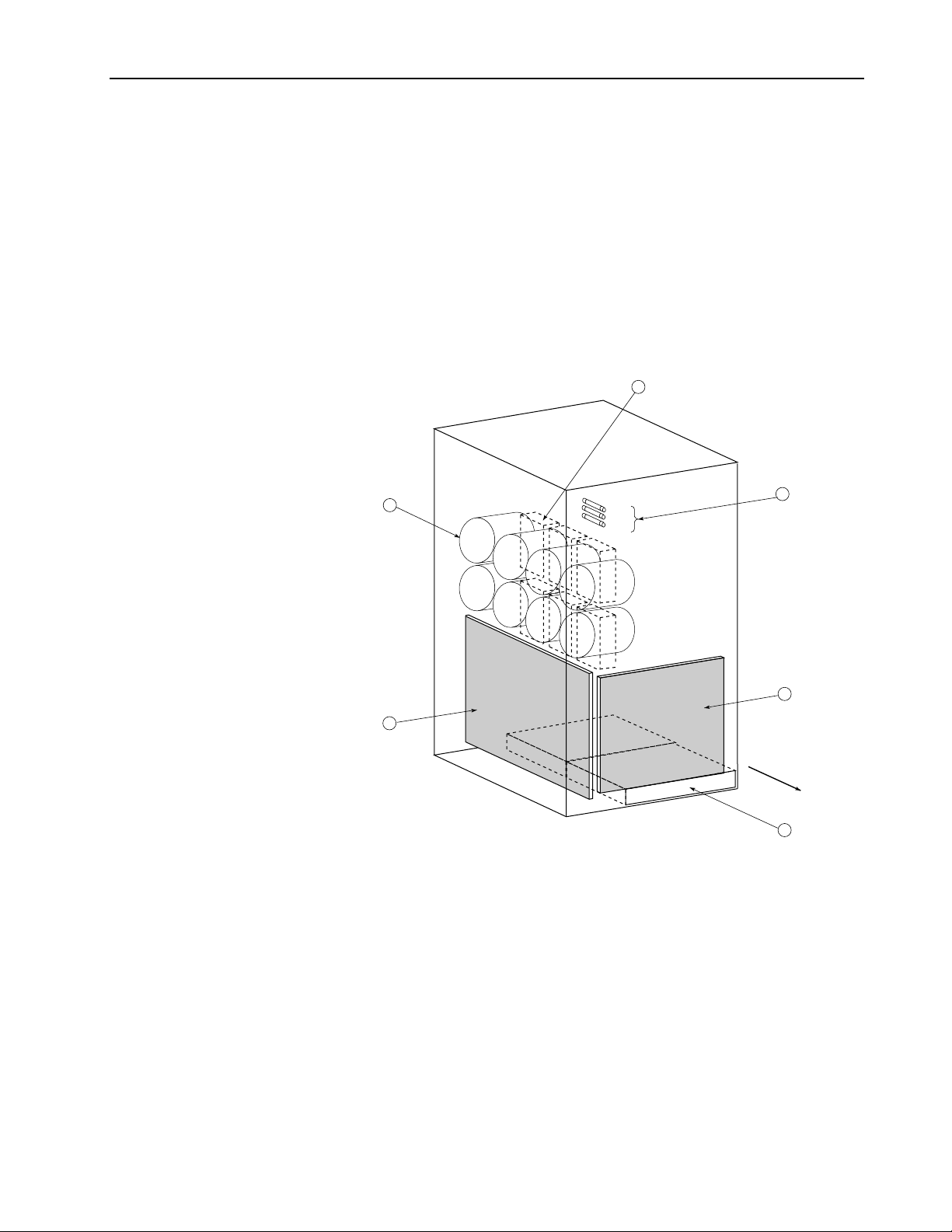
About 8720MC-RPS Regenerative Power Supply
Model 8720MC-RPS190BM and 8720MC-RPS190BS have the
following main components.
1. Regulator Board (BDSR) (only master unit has a Regulator
Board, not on slave unit)
2. Power Interface Board (PIFS)
3. Bus Capacitors
4. Cooling Fan
5. Power Modules
6. Fuses 1, 2, 3
The following figure shows the locations of main components of
Model 8720MC-RPS190BM and 8720MC-RPS190BS.
5
2-7
3
2
FU1
FU2
FU3
6
1
Unit Front Side
4
Page 20
2-8
READY
FAULT
PROGRAMkWkW
About 8720MC-RPS Regenerative Power Supply
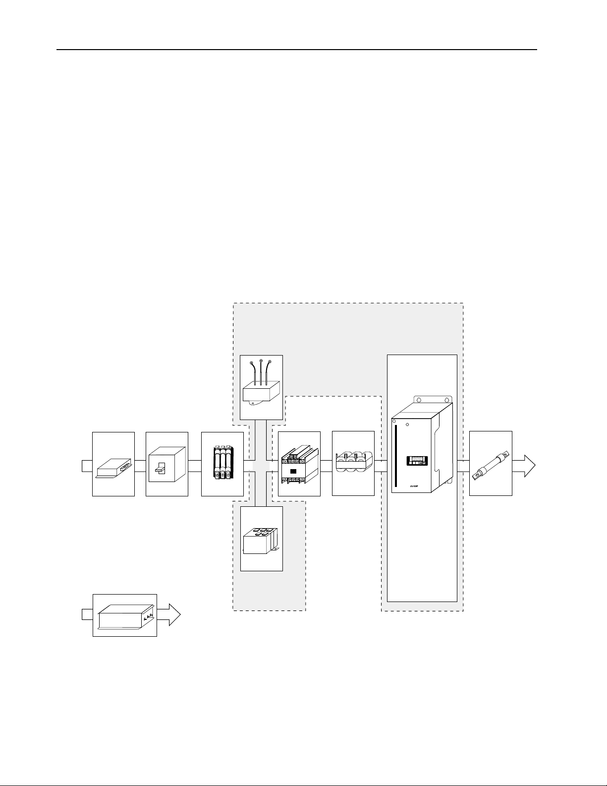
Model 8720MC-RPS027 and 8720MC-RPS065 are composed of the
following components.
1) 8720MC-RPS
2) Line filter for main circuit*
3) Line filter for sequence power*
4) Circuit breaker
5) AC input fuse
6) DC output fuse
7) Varistor
8) Harmonic filter
9) Main magnetic contactor
10) Reactor
* Not necessary when compliance with CE mark is not required.
The following figure shows system configuration of 8720MCRPS027 and 8720MC-RPS065.
8720MC-RPSxxxvm-HV2
2) Line Filter for
Main Circuit
*
3) Line Filter for
Sequence Power
4) Circuit
Breaker
*
5) AC
Input Fuse
7) Varistor
8720MC-VA-B
9) Main
Magnetic
Contactor
8) Harmonic Filter
8720MC-HF-B2
10)
Reactor
8720MC-LR
1) 8720MC-RPS
POWER
ss
4000
Synchronous Rectifier
A
READY
FAULT
V
PROGRAM
ENT
PRG
RST
6)DC Output
Fuse
Page 21
READY
FAUL
PROGRAM
kW
About 8720MC-RPS Regenerative Power Supply
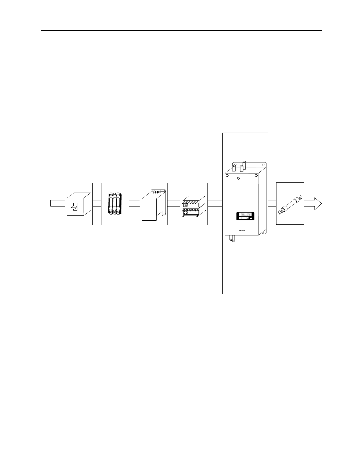
Model 8720MC-RPS190 is composed of the following components.
1) 8720MC-RPS
2) Circuit breaker
3) AC input fuse
4) DC output fuse
5) EMC filter unit
6) ACL unit
The following figure shows system configuration of Model
8720MC-RPS190.
1) 8720MC-RPS
2-9
2) Circuit
Breaker
3) AC Input
Fuse
5) EMC
Filter Unit
8720MC-EF
6) ACL Unit
8720MC-LR
POWER
ss
4000
Synchronous Rectifier
A
READY
FAUL
T
V
PROGRAM
kW
ENT
PRG
RST
For more information, refer to Chapter 4 of this manual.
4) DC Output
Fuse
Page 22
2-10
About 8720MC-RPS Regenerative Power Supply
Terminal Blocks on the Main Circuit
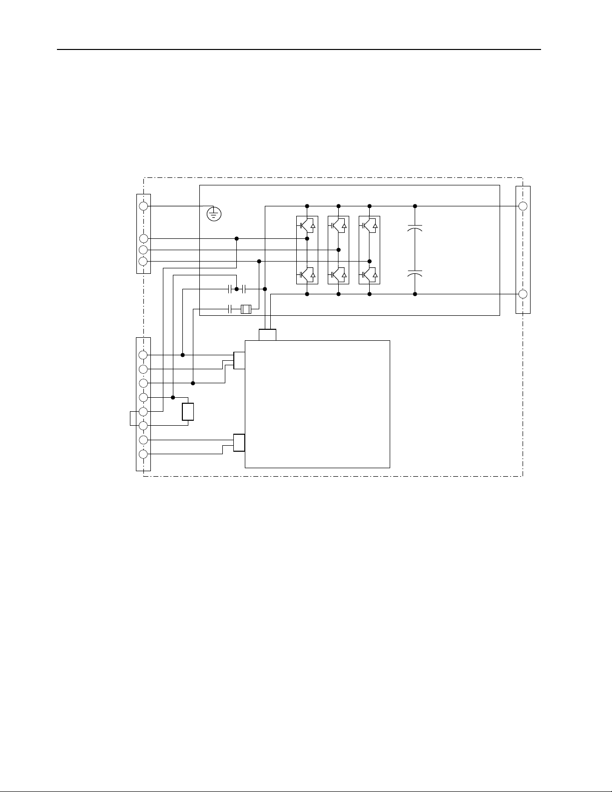
This section provides the main circuit block diagram and the
description of the main power terminal block (TB1) and the control
power terminal block (TB2). The main circuit block diagram for
Model 8720MC-RPS027BM, 8720MC-RPS065BM and 8720MCRPS065BS is shown in Figure 2.1.
Figure 2.1
Terminal Blocks on the Main Circuit for RPS027 and RPS065 units
TB1
G
L
1
L
2
L
3
PR
PR FUSE1
TB2
L
1AUX
L
2AUX
L
3AUX
PR1
PR2
PR3
MC1
MC2
Precharge/
Discharge
Resistor
TB1
P
+
+
DIS
N
Driver Board RCPB
CN17
CN16
CN5
Power Interface Board PIFS
1> The G terminal for Model 8720MC-RPS027 is located on the front surface of the chassis.
Page 23
About 8720MC-RPS Regenerative Power Supply
Figure 2.2 shows the main circuit block diagram for Model
8720MC-RPS190BM and 8720MC-RPS190BS.
Figure 2.2
Terminal Blocks on the Main Circuit for RPS190 unit
2-11
L
L
L
1AUX
2AUX
3AUX
PR1
PR2
PR3
G
L
1
L
2
L
3
TB2
TB4
Precharge/
Discharge
Resistor
Fuse 3
PR
PR
DIS
Fuse 2
Fuse 1
CN17
CN16
Power Interface Board PIFS
CN5
CN5
CN16
BDI
BDI
P
N
MC1
MC2
CN20
APS
Page 24

2-12
About 8720MC-RPS Regenerative Power Supply
Main Power Terminal Block (TB1) for Model 8720MC-RPS027 and 8720MC-RPS065
The table below provides the information of the terminals on use of
the terminals on the main power terminal block (TB1) for Model
8720MC-RPS027 and 8720MC-RPS065.
Terminal Name
Main Power
Terminals
DC Bus Terminals
Grounding Terminal
Symbol
, L2, L
L
1
P, N
G
Description
To connect three-phase AC input power to
3
the main circuit.
For 460 V unit: 380 to 460 VAC +10%,
-15%, 50/60 Hz +/-5%
To connect the 8720MC-RPS Regenerative
Power Supply to load equipment.
To ground the 8720MC-RPS Regenerative
Power Supply.
Control Power Terminal Block (TB2) for Model 8720MC-RPS027 and 8720MC-RPS065
The table below describes the terminals on the control power
terminal block (TB2) for Model 8720MC-RPS027 and
8720MC-RPS065.
Terminal Name
Control Power Terminals
Terminals to Connect
Precharge/Discharge
Resistor
Control Terminals for
Main Magnetic Contactor
Symbol
L
1AUX
,
L
2AUX
,
L
3AUX
PR1,
PR2,
PR3
MC1,
MC2
Description
To connect three-phase AC input power to the
control circuit.
For 460 V unit: 380 to 460 VAC +10%, -15%,
50/60 Hz +/-5%
To connect precharge/discharge resistor.
When the built-in resistor is used:
Jumper between PR2 and PR3, and open
PR1.
When an external resistor is used:
Connect the resistor between PR1 and
PR2, and open PR3.
When the unit is connected for power
regeneration mode only:
Open all the terminals PR1, PR2 and
PR3.
To be used as the control terminals for the
main magnetic contactor (rated for 250 VAC/
1 Amp or 30 VDC/1 Amp).
Page 25

About 8720MC-RPS Regenerative Power Supply
2-13
Main Power Terminal Bar for Model 8720MC-RPS190
The table below describes the terminals on the main power terminal
bar for Model 8720MC-RPS190.
Terminal Name
Main Power
Terminals
DC Bus Terminals
Grounding Terminal
Symbol
, L2, L
L
1
P, N
G
Description
To connect three-phase AC input power to
3
the main circuit.
For 460 V unit: 380 to 460 VAC +10%,
-15%, 50/60 Hz +/-5%
To connect the 8720MC-RPS Regenerative
Power Supply to load equipment.
To ground the 8720MC-RPS Regenerative
Power Supply.
Control Power Terminal Block (TB2) and Control Terminal Block (TB4) for Model 8720MC-RPS190
The table below describes the terminals on the control power
terminal block (TB2) and the terminals on the control terminal
block (TB4) for Model 8720MC-RPS190.
T
B
2
T
B
4
Symbol
L
1AUX
,
L
2AUX
,
L
3AUX
PR1,
PR2,
PR3
+24V3
0V3
SENS
+24V2
0V2
MC1
MC2
Description
To connect three-phase AC input power to the
control circuit.
For 460 V unit: 380 to 460 VAC +10%, -15%,
50/60 Hz +/-5%
To connect precharge/discharge resistor.
When the built-in resistor is used:
Jumper between PR2 and PR3, and open
PR1.
When an external resistor is used:
Connect the resistor between PR1 and
PR2, and open PR3.
When the unit is connected for power
regeneration mode only:
Open all the terminals PR1, PR2 and
PR3.
To supply AC power to the fan for the AC reactor
unit through the EM4000 EMC filter unit.
To enter fault signal of the fan for the AC reactor
unit.
To supply power to the main magnetic contactor
and the fan for the cabinet fan through the
8720MC-EF190 EMC filter unit.
To be used as the control terminals for the main
magnetic contactor.
Terminal Name
Control Power
Terminal
Terminals to Connect
Precharge/Discharge
Resistor
AC Reactor Fan
Power Terminals
Terminals for Fan Fault
Signal
Power Terminals for
Main Magnetic
Contactor MC
and Optional Fan
Control Terminaks for
Main Magnetic
Contactor
Page 26
2-14
READY
FAULT
PROGRAM
kW
About 8720MC-RPS Regenerative Power Supply
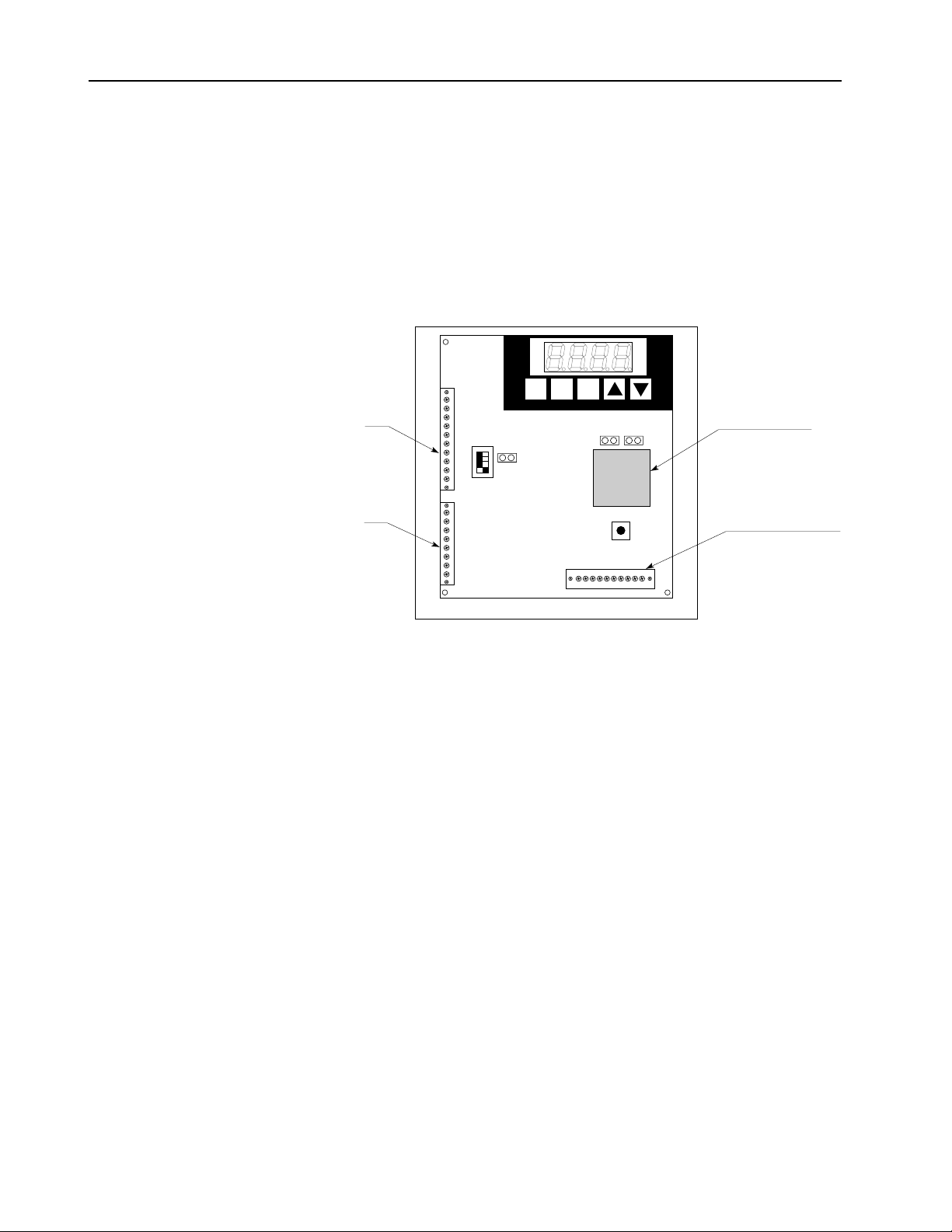
Regulator Board
The Regulator Board exists only on master unit. The slave unit for
parallel connection has no Regulator Board and is controlled by the
microprocessor of the Regulator Board on the master unit.
The 8720MC-RPS Regenerative Power Supply regulation is
performed by a microprocessor on the Regulator Board. The figure
below shows the locations of the main components on the Regulator
Board. The operation of the 8720MC-RPS Regenerative Power
Supply is adjusted by the parameters set by the keypad.
CN2
CN1
SW7
JP2
READY
FAULT
PROGRAM
RST
PRG
ENT
JP1 JP3
SW6
A
V
kW
Microprocessor
Sequence Signal
Terminal Block (TB3)
• PWM Gating Signals
Based on the output of the current/voltage control loop, the
Regulator Board sends PWM gating signals through the Power
Interface Board to the Power Modules (transistors), producing a
pulse-width-modulated (PWM) waveform.
• Sequence Output Signals
Sequence output signals are provided from the sequence signal
terminal block (TB3) of the Regulator Board to indicate the unit
status .
• Four-character Display and Six LEDs
A four-character seven-segment LED display is used to monitor
values, parameter numbers, parameter values, and error codes.
Six LEDs show the display mode of the operation panel and the
units of the monitored values.
Page 27

About 8720MC-RPS Regenerative Power Supply
Jumpers and Switches
ATTENTION: Only qualified electrical personnel
!
!
!
familiar with the construction and operation of this
equipment and the hazards involved should set
jumpers and switches. Read and understand this
manual in its entirety before proceeding. Failure to
observe this precaution could result in severe bodily
injury or loss of life.
ATTENTION: Do not press the reset button switch
(SW6) during operation. Also, do not alter the setting
of any jumpers and switches during operation.
Failure to observe this precaution could result in
destruction of the equipment, severe bodily injury or
loss of life.
ATTENTION: Do not alter the settings of any
jumpers not described in this manual. Failure to
observe this precaution could result in damage to, or
destruction of, the equipment.
2-15
The jumpers JP1 to JP3 and the switches SW6 and SW7 are set
before shipment from factory. If you need to change the jumpers
and/or switch settings, read and understand the following
description of these jumpers and switches before proceeding.
• Jumper JP1 to Enable Operation
Short this jumper to start switching operation of transistors of
the 8720MC-RPS Regenerative Power Supply when the RUN
sequence input is enabled. This jumper should always be kept
closed.
• Jumper JP2 to Enable Inspection Mode
Keep this jumper open always.
• Reset Switch SW6
Pressing this switch resets the CPU.
Important:
• Switch SW7 to Enable Base Block
This switch is used to stop switching of transistors that produce
PWM waveform by interrupting the base signal from the Power
Modules. To interrupt the base signal, turn the switch to the
OFF side.
As shown in the figure below, SW7 consists of four switches,
and SW7-1 to SW7-3 can be allocated to the master unit and
slave units 1 and 2. In the case of a master with paralleled slave
units, it is possible to interrupt the base signal of each unit by
turning the corresponding switch to the OFF side. SW7-4 must
always be kept to the OFF side.
Do not press the reset switch SW6 during operation.
Page 28

2-16
About 8720MC-RPS Regenerative Power Supply
When two units are connected in parallel, turn the switches
SW7-1 and SW7-2 to the ON side, and when three units are
connected in parallel, turn the switches SW7-1 through SW7-3
to the ON side.
Slave Unit 2
Slave Unit 1
Master Unit
SW7-4
SW7-3
SW7-2
SW7-1
ON
ENABLE BASE BLOCK
OFF
Keep SW7-4 always to the OFF side.
When the switch is turned to the OFF side, the base signal is
interrupted, and the unit will be in the OFF condition.
When the switch is turned to the ON side, the base signal is
kept ON, and PWM switching will continue.
Page 29
About 8720MC-RPS Regenerative Power Supply
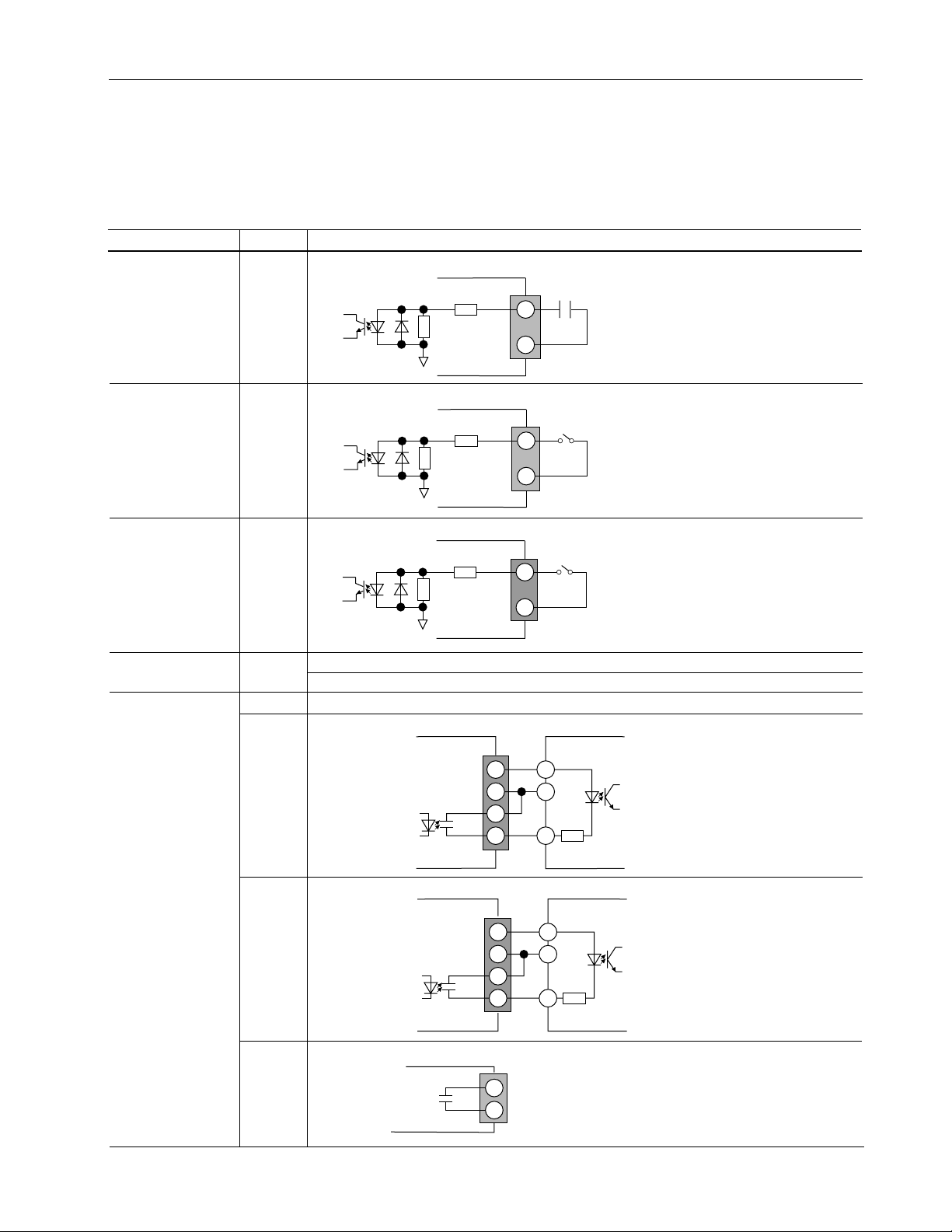
Sequence Signal Terminal Block (TB3)
As shown in the figure in page 2-14, there is a sequence signal
terminal block (TB3) on the Regulator Board. The following table
provides the information on each terminal of TB3.
2-17
Name of Terminal
Sequence Input
Signals
Power for
Sequence Signals
Sequence Output
Signals
Symbol
MC
RST
PWR
0 V
24 V
COM
IP
RDY
Description
Enter the supplemental contact signal (normally open contact) of the main magnetic contactor.*
4.7K
MC
1K
24V
8720MC-RPS
The reset signal (+24 VDC) is used to reset fault. Close this reset signal as required.*
4.7K
RST
1K
24V
8720MC-RPS
Enter the RUN signal (+24 VDC)*.
4.7K
PWR
1K
24V
8720MC-RPS
0 V of +24 VDC power.
+24 VDC power (rating : 24 VDC/0.2 Amps).
Common for IP and RDY signals.
This is a contact signal that is turned ON during instantaneous power loss (contact rating : 30 VDC/
50 mA).
24V
0V
COM
IP
8720MC-RPS
This is a contact signal that is turned ON while the unit is ready for operation (contact rating : 30 VDC/
50 mA).
24V
0V
COM
RDY
8720MC-RPS
MC
+VC
0VC
IP
4.64K
+VC
0VC
RDY
4.64K
* Because driving current of sequence input signals
is 5mA and below, use a contact of which
minimum applicable load is 5mA and below.
* Because driving current of sequence input signals
is 5mA and below, use a contact of which
minimum applicable load is 5mA and below.
* Because driving current of sequence input signals
is 5mA and below, use a contact of which
minimum applicable load is 5mA and below.
Load
Load
FR, FR
This is a contact signal that opens while fault occurs (contact rating : 250 VAC/1 Amp or 30 VDC/
1 Amp).
8720MC-RPS
FR
FR
Page 30

2-18
About 8720MC-RPS Regenerative Power Supply
End of Chapter
Page 31

Chapter
Installation
This chapter shows how to mount the 8720MC-RPS Regenerative
Power Supply properly, and provides information on the items to be
checked.
3
Installation Site
ATTENTION:
!
!
It is important to properly plan before installing the 8720MC-RPS
Regenerative Power Supply to ensure that the environment and
operating conditions of the units are satisfactory. Read this section
before continuing with the unit installation.
familiar with the construction and operation of this
equipment and the hazards involved should install,
adjust, operate, or service this equipment. Read and
understand this manual in its entirety before
proceeding. Failure to observe this precaution could
result in destruction of the equipment, severe bodily
injury, or loss of life.
ATTENTION:
with all applicable local, national and international
codes. Failure to observe this precaution could result
in damage to, or destruction of, the equipment.
Only qualified electrical personnel
The user is responsible for conforming
Environmental Conditions to be Met
The Declaration of Conformity with the requirements for CE Mark
was issued for the following units, and these units must be used in
cabinet.
8720MC-RPS027BM,
8720MC-RPS065BM, 8720MC-RPS065BS,
8720MC-RPS190BM and 8720MC-RPS190BS
Also, before deciding on an installation site, consider the following
guidelines:
• Verify that the units can be kept clean, cool and dry.
• Be sure that the units are always away from oil, metal powder,
other airborne contaminants, and direct sunlight.
• Check that the units will not be exposed to excessive vibration
and noise, and that they will not be close to instruments
sensitive to electrical noise.
• The area chosen should allow the space required for proper air
flow as defined in the following.
Page 32

3-2
Installation
• Check that the temperatures within the vicinity of the units are
between -10 to 50 degree C (14 to 122 degree F). In case of
8720MC-RPS190, however, the ambient temperature must be
between -10 to 40 degree C (14 to 104 degree F).
• Check that the relative humidity is between 5 and 95% without
condensation.
• Do not install the units above 1,000 meters (3,300 feet) without
derating output power. For every 300 meters (1,000 feet) above
1,000 meters (3,300 feet), derate the output power 4%. When
you need to install the units above 1,500 meters (5,000 feet),
contact The Allen-Bradley Company.
In case of Model 8720MC-RPS190BM and 8720MC-RPS190BS,
it is possible to ship the units from the factory after mounting each
of these units in a cabinet together with the required peripheral
devices and installing wiring in the cabinet. When the user
purchases from The Allen-Bradley Company the units mounted in
the cabinet, the above-mentioned guidelines should be considered
for selection of the installation site.
Required Total Area
Overall unit dimensions are shown in Figures 3.1 and 3.2. Figure
3.1 illustrates the dimensions of Model 8720MC-RPS027 and
8720MC-RPS065 units, and Figure 3.2 shows the outline
dimensions of 8720MC-RPS190 unit. Also as an aid in calculating
the required total area, Figures 3.3 and 3.4 show the required
distance between two adjacent units in case of two or three
paralleled units of Model 8720MC-RPS027 and 8720MC-RPS065,
and Figures 3.5 and 3.6 show the required distance between two
adjacent units in case of two or three paralleled units of Model
8720MC-RPS190 unit installed in a cabinet provided by the user.
Page 33

Installation
REGENERATIVE POWER SUPPLY
MC
READY
FAULT
PROGRAM
3-3
Figure 3.1
Overall Dimensions of a Single Unit of Model 8720MC-RPS027 and 8720MC-RPS065
Units
H dia.
G dia.
8720
READY
FAULT
PROGRAM
MC
R
C
A
V
kW
ENT
PRG
RST
P
P
S
U
R
W
E
P
IV
O
T
E
A
R
E
N
E
G
E
E
K
F
B
D
LY
Model
8720MC-
RPS065
8720MC-
RPS027
A
179.4
(7.06)
167
(6.57)
H
C
A
B
395
(15.6)
320
(12.6)
C
127
(5.0)
120
(4.72)
E
D
333.2
(131.2)
260
(10.24)
F
E
10
(0.39)
10
(0.39)
F
30
(1.2)
30
(1.2)
G
18
(0.71)
17
(0.67)
H
9
(0.35)
8.2
(0.32)
K
9
(0.35)
8
(0.31)
L
L
318.3
(12.53)
310
(12.20)
Unit: Millimeter (Inch)
Page 34

3-4
REGENERATIVE POWER SUPPLY
8720
MC
READY
FAUL
PROGRAM
kW
Installation
Figure 3.2
Overall Dimensions of a Single Unit of Model 8720MC-RPS190 Unit
20 (0.79)
639.5 (25.18)
566.5 (22.30)
(2.34)
30
(1.2)
59.5
(2.3)
L
2
58
READY
FAUL
T
PROGRAM
RST
8720
125
(4.92)
L1, L
PRG
MC
E
R
ENT
G
N
E
M10
T
A
R
E
3
A
V
kW
IV
P
E
O
W
10 (0.39) dia.
20 (0.79) dia.
Y
L
P
P
S
U
R
E
40 (1.6)
13 (0.5)
14 (0.6)
503 (19.8)
550 (21.7)
573 (22.6)
110 (4.3) 110 (4.3)
L
1
86 (3.4)
L
2
L
3
33
(1.3)
20 (08)
P
N
30
(1.2)
(2.34)
59.5
E
125 (4.9)
242 (9.6)
M8
10
(0.4)
30 (1.2)
10 (0.4)
435 (17.1)
P
N
45
(1.8)
(3.3)
Unit: Millimeters (Inch)
E
83
Page 35

Installation
REGENERATIVE POWER SUPPLY
MC
REGENERATIVE POWER SUPPLY
MC
REGENERATIVE POWER SUPPLY
MC
Max. 250 (9.8)
Unit: Millimeter (Inch)
R
E
G
E
N
E
R
A
T
IV
E
P
O
W
E
R
S
U
P
P
L
Y
REGENERATIVE POWER SUPPLY
87208720
MC
RST
PRG
ENT
READYREADY
FAULTFAULT
PROGRAMPROGRAM kWkW
V
A
R
E
G
E
N
E
R
A
T
IV
E
P
O
W
E
R
S
U
P
P
L
Y
REGENERATIVE POWER SUPPLY
87208720
MC
Note: In case two units of Model 8720MC-RPS027 or 8720MC-RPS065 unit are installed in parallel,
the master unit must be on the right hand side as shown in the above.
Figure 3.3
Required Distance between Units in Case of Two Paralleled Units of
Model 8720MC-RPS027 or 8720MC-RPS065 Units
3-5
Figure 3.4
Required Distance between Units in Case of Three Paralleled Units of
Model 8720MC-RPS027 or 8720MC-RPS065 Units
READY
FAULT
PROGRAM kW
PRG
RST
MC
8720
IV
T
A
R
E
N
E
G
E
R
Y
L
P
P
S
U
R
W
P
E
O
E
Max. 250 (9.8)
8720
MC
E
R
Y
L
P
P
S
U
R
W
P
E
IV
T
O
E
A
R
E
N
E
G
Max. 250 (9.8)
8720
MC
E
R
N
E
G
A
V
ENT
Y
L
P
P
S
U
R
W
P
E
IV
T
O
E
A
R
E
Note: In case three units of Model 8720MC-RPS027 or 8720MC-RPS065 unit are installed in parallel,
the master unit must be installed at the rightmost end as shown in the above.
Unit: Millimeter (Inch)
Page 36

3-6
REGENERATIVE POWER SUPPLY
8720
MC
READY
FAUL
PROGRAM
kW
REGENERATIVE POWER SUPPLY
8720
MC
REGENERATIVE POWER SUPPLY
8720
MC
READY
FAUL
PROGRAM
kW
REGENERATIVE POWER SUPPLY
8720
MC
REGENERATIVE POWER SUPPLY
8720
MC
Installation
Figure 3.5
Required Distance between Units in Case of Two Paralleled Units of
Model 8720MC-RPS190 Unit
POWER POWER
8720
READY
PROGRAM
C
M
R
Y
L
P
P
S
W
U
R
IV
P
T
E
E
O
A
R
E
N
E
G
E
8720
Max. 620 (24.4)
A
FAUL
T
V
kW
ENT
PRG
RST
C
M
R
Y
L
P
P
S
W
U
R
IV
P
T
E
E
O
A
R
E
N
E
G
E
Unit: Millimeters (inch)
Note: In case two units of Model 8720MC-RPS190 unit are installed in parallel, the master unit
must be installed on the right hand side as shown in the above.
Figure 3.6
Required Distance between Units in Case of Three Paralleled Units of
Model 8720MC-RPS190 Unit
POWER
POWER POWER
READY
A
FAUL
T
V
kW
ENT
PRG
RST
C
M
R
Y
L
P
P
S
W
U
R
IV
P
T
E
E
O
A
R
E
N
E
G
E
Unit: Millimeters (inch)
8720
PROGRAM
C
M
E
R
IV
T
E
A
R
E
N
E
G
Y
L
P
P
S
W
U
R
P
E
O
Max. 620 (24.4)
C
M
8720
E
R
Y
L
P
P
S
W
U
R
IV
P
T
E
E
O
A
R
E
N
E
G
Max. 620 (24.4)
8720
Note: In case three units of Model 8720MC-RPS190 unit are installed in parallel, the master unit must
be installed at the rightmost end as shown in the above.
Page 37

REGENERATIVE POWER SUPPLY
MC
PROGRAM
Installation
Recommended Air Flow Clearance
Be sure that there is adequate clearance for air ventilation around
the 8720MC-RPS Regenerative Power Supply. Cooling air flows
from the bottom to the top of the units. For best cooling effect, do
not mount the 8720MC-RPS Regenerative Power Supply directly
above each other. The figure below shows recommended air flow
clearance.
Exhaust
150
(5.9)
3-7
150
(5.9)
Notes on Installation
8720
READY
FAULT
PROGRAM
MC
150
(5.9)
A
V
kW
ENT
PRG
RST
Y
L
P
P
W
IV
R SU
P
T
E
E
O
A
R
E
N
E
G
E
R
150
(5.9)
Intake
Unit: Millimeter (Inch)
When mounting the 8720MC-RPS Regenerative Power Supply, pay
attention to the following:
• Mount the units vertically.
• When two or three units of 8720MC-RPS Regenerative Power
Supply are installed in parallel, install the master unit at the
rightmost end viewed from the front side.
• Be sure that the ambient temperatures surrounding the units is
between -10 to 50 degree C (14 to 122 dgree F). In case of
Model 8720MC-RPS190BM and 8720MC-RPS190BS units, the
ambient temperature is -10 to 40 degree C (14 to 104 degree F).
To cool down the temperature in the cabinet, provide sufficient
space to allow adequate air flow over the components. If
necessary, add circulating fans to assure good convective heat
transfer.
• Do not mount any devices behind the units. This area must be
kept clear of all power wiring (control power wiring, main
power supply wiring and DC bus power wiring).
Page 38

3-8
Installation
• Do not expose the units to excessive electrical noise. If it is not
avoidable to install the 8720MC-RPS Regenerative Power
Supply close to a noise source or to use the units in environment
where noise trouble is expected, take sufficient noise
suppression measures.
Page 39

Chapter
Wiring
This chapter provides instructions on how to properly wire the
8720MC-RPS Regenerative Power Supply units. It also provides
information on the selection of the circuit breaker, the main
magnetic contactor, reactor, and the harmonic filter, etc.
4
ATTENTION:
!
!
!
!
familiar with the construction and operation of this
equipment and the hazards involved should install,
adjust, operate, or service this equipment. Read and
understand this manual in its entirety before
proceeding. Failure to observe this precaution could
result in destruction of the equipment, severe bodily
injury or loss of life.
ATTENTION:
with all the applicable codes. Wiring practices,
grounding, disconnects, and overcurrent protection
are of particular importance. Failure to observe this
precaution could result in severe bodily injury or loss
of life.
ATTENTION:
continuity checks in the equipment. Use higher range
of a circuit tester for this purpose. Failure to observe
this precaution could result in damage to, or
destruction of, the equipment.
ATTENTION:
with all applicable local, national and international
codes. Failure to observe this precaution could result
in damage to, or destruction of, the equipment.
Only qualified electrical personnel
The user is responsible for conforming
Do not use a megger to perform
The user is responsible for conforming
Recommended Wire Sizes
This section shows the recommended wire sizes for the wires to be
used in cabinet. Select the wire sizes in consideration of the
following:
• Applicable local, national and international codes.
• Temperature increase and voltage drop due to type of wires,
wiring method, wiring distance, etc.
Page 40

4-2
Wiring
Recommended Wire Sizes for Power Wiring to the Main Power Terminal Block (TB1) and the Main Power Terminal Bars
Table 4.1 to 4.3 show the recommended wire sizes for power wiring
to the main power terminal block (TB1) and the Main Power
Terminal Bars. Table 4.1 shows the wire sizes for Model 8720MCRPS027 unit, Table 4.2 shows the wire sizes for Model 8720MCRPS065 unit, and Table 4.3 shows the wire sizes for Model
8720MC-RPS190 unit. The wire sizes shown assume full utilization
of the rated capacity of the RPS unit.
Table 4.1
Recommended Maximum Wire Sizes for Model 8720MC-RPS027 Unit
Name of Terminal
Main Terminals (Input)
DC Bus Terminals (Output)
Grounding Terminal (Earth)
Symbol
L1, L2, L
P, N
G
Screw Size
3
M5
M5
M5
Size of Wire AWG/mm
#10 / 5.5 mm
#10 / 5.5 mm
#10 / 5.5 mm
Table 4.2
Recommended Maximum Wire Sizes for Model 8720MC-RPS065 Unit
Name of Terminal
Main Terminals (Input)
DC Bus Terminals (Output)
Grounding Terminal (Earth)
Symbol
L1, L2, L
P, N
G
Screw Size
3
M6
M6
M6
Size of Wire AWG/mm
#4 / 22 mm
#4 / 22 mm
#5 / 22 mm
2
2
2
2
2
2
2
2
Table 4.3
Recommended Maximum Wire Sizes for Model 8720MC-RPS190 Unit
Name of Terminal
Main Power Supply
Terminals
Symbol
L1, L2, L
Screw Size
M10
3
Size of Wire AWG/mm
Larger than 38
mm2 - 2 in parallel
2
Attached Lugs
JST, R38-10
(M10) (6 Pieces)
(1)
(AWG #2 - 2 in
parallel)
DC Bus Terminals
Grounding Terminal
(1)
UL-listed wires must be lugged by attached lugs.
JST is Japan Solderless Terminal Co.
P, N
G
M10
M8
Larger than 100mm
(AWG #4/0)
Larger than 38mm
(AWG #2)
2
JST, R100-10
(M10) (2 Pieces)
2
JST, R38-8 (M10)
(1 Piece)
Recommended Wire Sizes for Power Wiring to the Control Power Terminal Block (TB2) and the Control Terminal Block (TB4)
Table 4.4 shows the recommended wire sizes for power wiring to
the control power terminal block (TB2) and the control terminal
block (TB4).
Table 4.4
Recommended Wire Sizes for Power Wiring to the Control Power Terminals
and the control terminal block (TB4)
Name of Terminal
Main Terminals (Input)
DC Bus Terminals (Output)
Grounding Terminal (Earth)
Symbol
L
, L
2AUX
, L
1AUX
PR1, PR2, PR3
MC1, MC2
3AUX
Size of Wire
2
3.5 mm
(AWG #12)
3.5 mm2 (AWG #12)
2.0 mm2 (AWG #14)
Page 41

Wiring
4-3
AC Input Power Wiring for Model 8720MC-RPS027 and 8720MC-RPS065
ATTENTION:
!
!
!
Regenerative Power Supply units using high speed
switching elements generates noise regarding
emission due to noise generated during switching.
To avoid influence of such noise, it is very important
to use as thick and short grounding wire as possible.
ATTENTION:
disconnecting device, a main magnetic contactor and
an AC reactor in the AC input power line. When
8720MC-RPS027 and 8720MC-RPS065 must
conform with the requirements of CE Mark, install a
line filter in the AC input power line. Failure to
observe these precautions could result in damage to,
or destruction of, the equipment.
ATTENTION:
is connected to AC input power line of 8720MC-RPS
Regenerative Power Supply unit, large distortion may
be produced in the AC input power voltage and the
8720MC-RPS Regenerative Power Supply may not
operate normally. Remove such large distortion from
the AC input power voltage.
Equipment as the 8720MC-RPS
It is required to install a power
When a thyristor or similar equipment
The capacity (rating) of the 8720MC-RPS Regenerative Power
Supply depends on the number of units connected in parallel, i.e.,
single unit, two paralleled units, or three paralleled units. The
relation between the number of paralleled units and the unit
capacity is shown in Table 2.1.
Figure 4.1 to 4.3 show typical connection of AC input power wiring
for Model 8720MC-RPS027 and 8720MC-RPS065 units. Figure
4.1 shows AC input power wiring for the single unit, and Figures
4.2 and 4.3 show AC input wiring for parallel connection of two
units and three units respectively. Install appropriate reactors,
magnetic contactors, disconnects, line filters, etc. at the positions
shown in these figures.
The phases of the AC input power to the main power supply
terminals L1, L2 and L3 must be same as the phases of the control
power to the control power terminals L
case of paralleled units, the phases of the control power L
and L
master unit.
for the slave unit(s) must also be same as those for the
3AUX
1AUX
, L
2AUX
, and L
3AUX
1AUX
. In
, L
2AUX
,
Page 42

4-4
Wiring
Line Filter <5
380 to
460 VAC
for AC Input
Power
100 to 115 VAC
200 to 230 VAC
Circuit
Breaker <4
(CB)
or
Fuse <4
for
Power
Supply
Single-phase
Line Filter <5
ATTENTION:
!
to the 8720MC-RPS Regenerative Power Supply when
connecting multiple units in parallel. The phases of AC
Special caution must be paid to wiring
input power to the main power supply terminals (L1, L
and L3) and to the control power terminals (L
L
2AUX
, and L
) and the polarity of DC bus output (P
3AUX
and N) of all the connected units must be the same.
Failure to observe this precaution could result in
destruction of the equipment, severe bodily injury or
loss of life.
Figure 4.1
Typical Connection of AC Input Power Wiring for Single Unit of
Model 8720MC-RPS027 and 8720MC-RPS065
8720MC-RPS
Regenerative
Power Supply
Unit
L
1
L
2
L
3
L
1AUX
L
2AUX
L
3AUX
PR1
PR2
PR3
MC1
MC2
P
N
G
PWR
MC
24V
Terminal Block for Main
Power Supply (TB1)
Protection Fuse <2
Terminal Block for
Sequence Signals (TB3)
RUN On/Off
MC
Varistor
Harmonic
Filter
E
<8, 9
MC
Main
Magnetic
Contactor
(MC)
Reactor <11
<1
Terminal Block for
Control Power (TB2)
,
1AUX
Terminals P and N <6
of Load Equipment
<10
2
1> The phases of the AC input power to the main supply terminals L1, L2 and L3 must be same as those of the control power
to the control power terminals L
2> It is recommended to install the DC bus protection fuses on the both lines to the terminals P and N to prevent ground fault,
when more than one drive is connected to the 8720MC-RPS Regenerative Power Supply.
3> Turn ON the switch SW7-1 on the Regulator Board without fail.
4> Both a three-phase circuit breaker and fuses are not required. Check your local code to determine if fuses should be
used instead of a circuit breaker.
5> When the 8720MC-RPS Regenerative Power Supply must conform with the requirements of CE Mark, install a line filter in
the AC input power line and a single-phase line filter in the power supply line to the main magnetic contactor.
6> The length of the DC bus wiring runs should not exceed 2 meters. It is also recommended to use twisted shielded cable.
7> The length of the wiring in the cabinet must be as short as possible.
8> The length of the wiring from the E terminal of the Harmonic Filter to the Grounding Terminal must be as short as possible.
9> The physical location of the Harmonic Filter and Varistor relative to the Contactor and Line Reactor is important.
Connect these devices in the relative positions shown in this illustration.
10> Because driving current of sequence input signals is 5mA and below, use a contact of which minimum applicable load is 5mA and below.
11> Use the reactor in maximum surrounding air temperature of 55 degree C (131 degree F) and below.
1AUX
, L
2AUX
and L
3AUX
.
Page 43

380 to
460 VAC
Line Filter <6
for AC
Input
Power
Circuit
Breaker <4
(CB2)
Fuse <4
for
Power
Supply
Wiring
Figure 4.2
Typical Connection of AC Input Power Wiring for Two Paralleled Units of
Model 8720MC-RPS027 and 8720MC-RPS065
8720MC-RPS
Regenerative Power
Varistor
Main
Magnetic
Contactor
(MC2)
Reactor
(L2)
<12
Supply Unit 2
(Slave Unit)
L
L
L
P
1
N
2
G
3
Protection
Fuse <2
Terminals
P and N
of Load
Equipment
4-5
<7
100 to
115 VAC
or
200 to
230 VAC
Single-phase
Line Filter <6
Line Filter <6
for AC
Input
Power
CB2
Circuit
Breaker <4
(CB1)
Fuse <4
for
Power
Supply
<9, 10
MC2
<9, 10
MC1
Harmonic
Filter
E
Varistor
Harmonic
Filter
E
MC2
Main
Magnetic
Contactor
(MC1)
<12
Reactor
(L1)
<1
MC1
L
1AUX
L
2AUX
L
3AUX
PR1
PR2
PR3
MC1
MC2
8720MC-RPS
Regenerative Power
Supply Unit 1
(Master Unit)
1
2
3
1AUX
2AUX
3AUX
P
N
G
L
L
L
L
L
L
PR1
PR2
PWR
PR3
MC
MC1
24V
MC2
Protection
Fuse <2
RUN On/Off
MC1
MC2
<5, 11
CB2
1> The phases of the AC input power to the main supply terminals L
L
, L
2AUX
and L
1AUX
2> It is recommended to install the DC bus protection fuses on the both lines to the terminals P and N to prevent ground fault, when more
. The phases of the control power L
3AUX
1AUX
, L2 and L
1
, L
must be same as those of the control power to the control power terminals
3
2AUX
and L
for the slave unit(s) must also be same as those for the master unit.
3AUX
than one drive is connected to the 8720MC-RPS Regenerative Power Supply.
3> Turn ON the switches SW7-1 and SW7-2 on the Regulator Board without fail.
4> Both a three-phase circuit breaker and fuses are not required. Check your local code to determine if fuses should be used instead of a circuit breaker.
5> The slave circuit breaker must be provided with an auxiliary contact as a safety interlock to the master. Use fuses with a slightly higher current rating
if your local code requires them.
6> When the 8720MC-RPS Regenerative Power Supply must comform with the requirements of CE Mark, install a line filter in the AC input power line and
a single-phase line filter in the power supply line to the main magnetic contactor.
7> The length of the DC bus wiring runs should not exceed 2 meters. It is also recommended to use Bus bar for the common bus sized to 1.75 times the total
continuous current output of the RPS units.
8> The length of the wiring in the cabinet must be as short as possible.
9> The length of the wiring from the E terminal of the Harmonic Filter to the Grounding Terminal must be as short as possible.
10> The physical location of the Harmonic Filter and Varistor relative to the Contactor and Line Reactor is important. Connect these devices in the relative positions
shown in this illustration.
11> Because driving current of sequence input signals is 5mA and below, use a contact of which minimum applicable load is 5mA and below.
12> Use the reactor in maximum surrounding air temperature of 55 degree C (131 degree F) and below.
Page 44

4-6
Wiring
Figure 4.3
Typical Connection of AC Input Power Wiring for Three Paralleled Units of
Model 8720MC-RPS027 and 8720MC-RPS065
8720MC-RPS
Regenerative Power
Supply Unit 3
(Slave Unit 2)
Protection
1
N
L
2
G
L
3
L
1AUX
L
2AUX
L
3AUX
PR1
PR2
PR3
MC1
MC2
8720MC-RPS
Regenerative Power
Supply Unit 2
(Slave Unit 1)
Protection
Fuse <2
P
L
1
N
L
2
G
L
3
L
1AUX
L
2AUX
L
3AUX
PR1
PR2
PR3
MC1
MC2
8720MC-RPS
Regenerative Power
Supply Unit 1
(Master Unit)
Protection
Fuse <2
P
L
1
N
L
2
G
L
3
<1
L
1AUX
L
2AUX
L
3AUX
PR1
PR2
PR3
MC1
MC2
must be same as those of the control power to the control power terminals
3
and L
for the slave unit(s) must also be same as those for the master unit.
AUX
3
PWR
MC
24V
RUN On/Off
MC1
MC2
MC3
CB2
Terminals P and N
of Load Equipment
CB3
Fuse <2
P
L
<7
<5, 11
Filter
Filter
E
E
Main
Magnetic
Contactor
(MC3)
MC3
Main
Magnetic
Contactor
(MC2)
Main
Magnetic
Contactor
(MC1)
Reactor
(L3)
Reactor
(L2)
Reactor
(L1)
<12
<12
<12
100 to 115 VAC
or
200 to 230 VAC
380 to
460 VAC
Single-phase
Line Filter
<6
Line Filter <6
for AC
Input
Power
Line Filter <6
for AC
Input
Power
Line Filter <6
for AC
Input
Power
Fuse <4
Circuit
Breaker <4
(CB3)
Breaker <4
Breaker <4
for
Power
Supply
CB3
Fuse <4
Circuit
(CB2)
for
Power
Supply
CB2 MC2
Fuse <4
Circuit
for
Power
(CB1)
Supply
Varistor
Harmonic
<9, 10
MC3
Varistor
Harmonic
<9, 10
MC2
Varistor
MC1
<9, 10
Harmonic
Filter
E
MC1
1> The phases of the AC input power to the main supply terminals L1, L2 and L
L
, L
2AUX
and L
1AUX
2> It is recommended to install the DC bus protection fuses on the both lines to the terminals P and N to prevent ground fault, when more
. The phases of the control power L
AUX
3
1AUX
, L
2AUX
than one drive is connected to the 8720MC-RPS Regenerative Power Supply.
3> Turn ON the switches SW7-1, SW7-2 and SW7-3 on the Regulator Board without fail.
4> Both a three-phase circuit breaker and fuses are not required. Check your local code to determine if fuses should be used instead of a circuit breaker.
5> The slave circuit breaker must be provided with an auxiliary contact as a safety interlock to the master. Use fuses with a slightly higher current rating
if your local code requires them.
6> When the 8720MC-RPS Regenerative Power Supply must comform with the requirements of CE Mark, install a line filter in the AC input power line and
a single-phase line filter in the power supply line to the main magnetic contactor.
7> The length of the DC bus wiring runs should not exceed 2 meters. It is also recommended to use Bus bar for the common bus sized to 1.75 times the total
continuous current output of the RPS units.
8> The length of the wiring in the cabinet must be as short as possible.
9> The length of the wiring from the E terminal of the Harmonic Filter to the Grounding Terminal must be as short as possible.
10> The physical location of the Harmonic Filter and Varistor relative to the Contactor and Line Reactor is important. Connect these devices in the relative positions
shown in this illustration.
11> Because driving current of sequence input signals is 5mA and below, use a contact of which minimum applicable load is 5mA and below.
12> Use the reactor in maximum surrounding air temperature of 55 degree C (131 degree F) and below.
Page 45

Wiring
4-7
When Model 8720MC-RPS027 or 8720MC-RPS065 is operated in the Power Regeneration Mode only
Figure 4.4
Wiring Model 8720MC-RPS027 or 8720MC-RPS065 Unit
Used as a Converter for the Power Regeneration Mode Only
8720MC-RPS027
and
8720MC-RPS065
Line Filter for
AC Input Power
Circuit
Breaker
(CB1)
100 to 115 VAC
or
200 to 230 VAC
Circuit
Breaker
(CB2)
Fuse
Single Phase
Line Filter
Varistor
Harmonic
Filter
E
<2
MC1
Main
Magnetic
Contactor
(MC1)
<7
<6
(Load Equipment)
Reactor
8720MC-RPS
Regenerative Power
Supply Unit
(Dedicated for Power
<9
Regeneration Mode)
Reactor
<1
Inverter
L
1
L
2
L
3
READY
L
1
L
2
L
3
L
1AUX
L
2AUX
L
3AUX
PR1
PR2
PR3
MC1
MC2
PWR
MC
24V
U
V
W
P
N
G
P
N
G
Protection Fuse <2
RUN On/Off
MC1
To AC Motor
READY
<8
1> The phases of the AC input power to the main supply terminals L
to the control power terminals L
2> It is recommended to install the DC bus protection fuses on the both lines to the terminals P and N to prevent ground fault,
when plural number of load equipment is connected to the 8720MC-RPS Regenerative Power Supply.
3> Turn ON the switch SW7-1 on the Regulator Board without fail.
4> Wiring to be taken into cabinet must be as short as possible.
5> This connection is only used with AC input drives.
6> The length of the wiring from the E terminal of the Harmonic Filter to the Grounding Terminal must be as short as possible.
7> The physical location of the Harmonic Filter and Varistor relative to the Contactor and Line Reactor is important.
Connect these devices in the relative positions shown in this illustration.
8> Because driving current of sequence input signals is 5mA and below, use a contact of which minimum applicable load is 5mA and below.
9> Use the reactor in maximum surrounding air temperature of 55 degree C (131 degree F) and below.
1AUX
, L
2AUX
and L
3AUX
.
, L2 and L3 must be same as those of the control power
1
It is possible to select the 8720MC-RPS units depending on the
regenerative power when only regenerated power of the unit
integrating converter and inverter is used. In this case, however,
the following cautions must be observed. Figure 4.4 shows wiring
of the 8720MC-RPS027 or 8720MC-RPS065 unit used as a
converter for the power regeneration mode only.
Page 46

4-8
Wiring
• Rating of regenerative power of the 8720MC-RPS is less than
rated power both in the instantaneous rating and continuous
rating.
• When rectifier portion of inverter is composed of thyristor, CR
snubber circuit between anode and cathode of thyristor may
become overloaded. Therefore, treating time for regenerative
power must be within 5 seconds for 3 minutes. Because the
current "ICR" flowing through CR snubber circuit in the power
regeneration mode is represented by the following formula,
verify the specifications of CR snubber circuit.
ICR[A] = (8 0.03 x R [Ω]) x C [µF]
• Do not fail to connect ACL unit of 3% impedance toward
inverter rating with the AC input line of inverter. Without ACL
unit, excessive circulating current will flow between the
8720MC-RPS units.
• Even during the power running, current will be supplied from
the 8720MC-RPS unit to DC bus proportionally to the impedance
ratio of both reactors at the 8720MC-RPS unit and inverter. This
current must not exceed the rating of the 8720MC-RPS unit.
• Set the parameter of the FWD Current Limit (U.001) to zero (0).
• Set the parameter of the Discharging Function Enable (F.017) to
zero (OFF).
• Set the DC bus voltage to start power regeneration to the
parameter of the DC Bus Voltage Reference (U.000).
• Open all the terminals PR1, PR2 and PR3 for connecting
precharge/discharge resistor. Because these terminals are open,
the unit does not perform precharge/discharge operations.
Precharge/discharge must be performed on inverter side.
• Do not fail to enter the READY signal of inverter to (PWR).
Page 47

Wiring
4-9
When Model 8720MC-RPS027 and 8720MC-RPS065 are adapted to Capacitors having large capacity
8720MC-RPS027 and 8720MC-RPS065 units charge to capacitors
with a single phase, full-wave rectification circuit through the
built-in precharge/discharge resistor. When the load capacitors
have large capacitance, it takes more time for charging, and the
wattage of the internal resistor becomes insufficient. When the
load capacitance is large, disable the built-in precharge/discharge
resistor and connect an external resistor or external circuit for
precharging/discharging (Note that minimum precharging/
discharging cycle is 3 minutes).
Calculate the rated wattage of the external precharge/discharge
resistor to be connected to the outside in accordance with the
following formula depending on the total capacitance of all the
capacitors including the built-in capacitor.
Rated wattage [W] = 17000 x C[F]
But, serge resistivity of J[J] = 28000 x C[F] must be provided.
When an external precharge/discharge resistor is connected
between PR1 and PR2, change the set value of the following
parameters, if necessary.
• Precharge/Discharge Time (F.014)
• Wattage of Precharge/Discharge Resistor (F.015)
Table 4.5
Maximum Applicable Capacitance of Capacitor and Minimum Resistance Value
Capacitance of built-in Capacitor
Built-in Resistor (Resistance
Value/Wattage)
External Resistor (Minimum Resistance
Value), Connect to PR1 and PR2
External Circuit (Minimum Resistance
Value), Refer to figure 4.5
8720MC-RPS027
990µF
4500µF
(33 ohm/80W)
55000µF
(30 ohm)
82500µF
(10 ohm)
8720MC-RPS065
1900µF
7000µF
(22 ohm/120W)
110000µF
(20 ohm)
220000µF
(4.7 ohm)
External resistor case
Most applications are successfully integrated using the internal
precharge resistor provided in the 8720MC-RPS Regenerative
Power Supply. For instances where there is a large amount of load
capacitance, caused by connecting several 8720MC drives to a
single 8720MC-RPS Regenerative Power Supply, an external
precharge resistor may be required. To determine the total
capacitance C[F] add the capacitance for the applicable RPS027 or
RPS065 unit, as determined from row 1 of Table 4.5, to the sum of
the drive capacitance as determined by the drive specifications in
Chapter 2 of the 8720MC-RPS User Manual, Publication 8720-UM001-B-US-P FEB 2001. In the case of the RPS027 if the total
capacitance is above 4,500µf, but less than 55,000µf an external
precharge resistor connected to PR1 and PR2 is required. In the
case of RPS065 if the total capacitance is above 7,000µf but less
than 110,000µf an external resistor connected to PR1 and PR2 is
Page 48

4-10
Wiring
required. Table 4.5 provides the minimum resistance value for the
external precharge resistor, 30 ohms in the case of the RPS027 and
20 ohms in the case of the RPS065. The wattage [W] is determined
by the equation presented above. Connect the external precharge
resistor to terminals PR1 and PR2 on terminal block TB2.
Terminal PR3 should be left open. See Chapter 2, Figure 2.1 under
"Terminal Blocks on the Main Circuit". The Precharge/Discharge
Time (F.014) may require a larger value to accommodate the
increased precharge time. The Wattage of Precharge/Discharge
Resistor (F.015) should also be increased to the external precharge
resistor wattage.
External circuit case
In the case of the RPS027 if the total capacitance is above 55,000µf
but less than 82,500µf an external precharge resistor connected as
shown in Figure 4.5 must be provided. In the case of the RPS065 if
the total capacitance is above 110,000µf but less than 220,000µf an
external resistor connected as shown in Figure 4.5 must be
provided. Table 4.5 provides the minimum resistance value for the
external precharge resistor, 10 ohms in the case of the RPS027 and
4.7 ohms in the case of the RPS065. The wattage [W] is
determined by the equation presented above.
Main
Power
PR1
PR2
PR3
Fuse
Varistor
Harmonic Filter
E
PWR
PRX
MC
Power for Sequence Circuit
MC
Figure 4.5
Example of Wiring when Precharge/Discharge Circuit of the 8720MC-RPS027 or
8720MC-RPS065 is configured with an External Circuit
PRX
TB1
G
<3
Reactor
MC
MC
PRX
DIS
DC Contactor
L
1
L
2
L
3
DIS
PR
PR
TB2
L
1AUX
L
2AUX
L
3AUX
PR1
PR2
<1
PR3
MC1
MC2
Fuse1
Precharge/
Discharge
Resistor
CN15
CN5
CN17
PIFS
MC
PWR
<2
PWR
RCPB
MC
MC
BDSR
24V
1> Remove the jumper between PR2 and PR3.
2> Because driving current of sequence input signals is 5mA and below,
use a contact of which minimum applicable load is 5mA and below.
3> Use the reactor in maximum surrounding air temperature of
55 degree C (131 degree F) and below.
TB1
P
N
DC Output
Fuse
DIS
DISR
DIS
If a totally external resistor network is used as shown in Figure 4.5,
the calculated wattage, [W] = 17,000 x C farads, is divided in half
to size the precharge and discharge resistors.
Page 49

Wiring
Parameter F.015 should be set to the sum of the wattage for both
resistors.
Installing Circuit Breaker
To protect the AC input power, install a circuit breaker with
supplemental contact (CB) in the AC input power line. Refer to
Figures 4.1 to 4.3 for the wiring. The rated ampacities of the
circuit breakers are as follows:
For Model 8720MC-RPS027BM unit : 50 Amps
For Model 8720MC-RPS065BM and
8720MC-RPS065BS units : 100 Amps
The following are the recommended circuit breakers with
supplemental contact.
For Model 8720MC-RPS027BM unit:
Fuji Electric - SA100BA/50WD
BU3ESB-50 W (UL-listed)*
Westinghouse - FDB3050*
or equivalent
4-11
For Model 8720MC-RPS065BM and 8720MC-RPS065BS units:
Fuji Electric - SA100BA/100WD
BU3ESB-100 W (UL-listed)*
Westinghouse - FDB3100*
or equivalent
* Because supplemental contact of this circuit breaker does not
conform with load of 5mA, relay with less than 5mA should be
used for connection when a supplemental contact is connected
with sequence input PWR.
Be sure to provide required quantity of circuit breakers with
supplemental contact (CB) for all units connected in parallel (see
Figure 4.2 or 4.3).
Installing Main Magnetic Contactor
The 8720MC-RPS Regenerative Power Supply uses a magnetic
contactor for turning the main power supply ON/OFF. Install and
wire the main magnetic contactors as shown in Figure 4.1 to 4.4.
After the RUN sequence signal entered and the precharge operation
is completed, the main magnetic contactor will be turned ON.
Conversely, when the RUN sequence signal is turned OFF, or when
a fault occurs, the main magnetic contactor will be turned OFF and
the discharge operation will begin.
The following are the recommended main magnetic contactors.
For Model 8720MC-RPS027BM unit:
Allen-Bradley - 100-C23x10 or 100-C30x10 (CE
marked) (where x is voltage suffix
code of operating coil)
Fuji Electric - SC-N1 (UL listed component)
Page 50

4-12
Wiring
For Model 8720MC-RPS065BM and 8720MC-RPS065BS units:
Allen-Bradley - 100-C43x10 (CE marked) (where x
is voltage suffix code of operating
coil)
Fuji Electric - SC-N2S (UL listed component)
(Select an adequate operating coil for the magnetic contactor
within the range of 100 to 230 VAC depending on the used
voltage.)
Be sure to provide required quantity of magnetic contactors (MC)
for all units connected in parallel (see Figure 4.2 or 4.3).
Installing Reactor
ATTENTION
!
!
The 8720MC-RPS Regenerative Power Supply boosts up and
controls the DC bus voltage, by utilizing the magnetic
characteristics of a reactor. Therefore, reactors are required for the
8720MC-RPS Regenerative Power Supply.
Install a single-phase type reactor to each of L1-phase, L2-phase and
L3-phase. Do not use three-phase AC reactors, since this will cause
unwanted coupling between the phases.
The following inductance of the reactor must be maintained in a
high frequency as 10 to 20 kHz. Note that use of a reactor for
commercial power supply may not maintain the required
inductance, resulting in increased heat generation or saturation due
to iron loss.
Regenerative Power Supply, the reactor is at a high
temperature. Do not touch the reactor during
operation or immediately after the unit has been
turned OFF. Failure to observe this precaution could
result in bodily injury.
ATTENTION
Regenerative Power Supply, the reactor operates at a
high temperature. Install the reactor in a location
where high temperature does not present a problem.
: During operation of the 8720MC-RPS
: During operation of the 8720MC-RPS
When multiple units are connected in parallel, a current unbalance
between the units is produced due to variation of reactor
inductance. To make the current difference between the connected
units as small as possible, use reactors having a variation of no
more than +/-2.5%.
Page 51

Wiring
The following are the designated reactors. These reactors are
integrated for three phases consisting of three single phase reactors.
When selected reactors are installed, set their capacity to the
parameter F.013.
Model 8720MC-LR14-070B (1200 micro-henry):
For Model 8720MC-RPS065BM and
8720MC-RPS065BS units that are used at 80 Amps or
less (capacity of applicable motor is 37 kW or less)
Model 8720MC-LR10-062B (1100 micro-henry):
For Model 8720MC-RPS065BM and
8720MC-RPS065BS units that are used at 60 Amps or
less (capacity of applicable motor is 30 kW or less).
Model 8720MC-LR05-048B (800 micro-henry):
For Model 8720MC-RPS065BM and
8720MC-RPS065BS units that are used at 48 Amps or
less (capacity of applicable motor is 22 kW or less).
Model 8720MC-LR03-032B (850 micro-henry):
For Model 8720MC-RPS027BM, 8720MC-RPS065BM
and 8720MC-RPS065BS units that are used at 32 Amps
or less (capacity of applicable motor is 15 kW or less).
4-13
The reactor should operate in an ambient temperature of 50 degree
C (122 degree F) or lower. If it is not avoidable to use a reactor
above 50 degree C (122 degree F) , decrease current 1% for every 1
degree C above 50 degree C.
Select temperature rating of wire to connect a reactor as follows.
For Model 8720MC-LR14-070B reactor used with current of
60 Amps or lower, and for Model 8720MC-LR10-062B,
8720MC-LR05-048B and 8720MC-LR03-032B reactors,
select a temperature rating 105 degree C (221 degree F) or
higher.
For Model 8720MC-LR14-070B reactor used with a current
between 60 and 80 Amps, select a temperature rating 130
degree C (266 degree F) or higher.
Be sure to provide required quantity of reactors for all units
connected in parallel (see Figure 4.2 or 4.3).
Installing Varistor
Install a varistor to absorb serge voltage between AC input power
wires. The following is the designated varistor.
For 8720MC-RPS027BM, 8720MC-RPS065BM and
8720MC-RPS065BS units: 8720MC-VA-B
Be sure to provide required quantity of varistors for all units
connected in parallel (see Figure 4.2 or 4.3). Also be sure to
connect the varistor on the incoming AC line side of the AC
contactor.
Page 52

4-14
Wiring
Installing Harmonic Filter
Install an adequate harmonic filter as shown in Figure 4.1, 4.2 or
4.3 to remove higher order harmonics generated by switching
operation of Power Modules, from AC input power. Also be sure to
connect the harmonic filter on the incoming AC line side of the AC
contactor. The following are the designated harmonic filter and
wire size.
8720MC-HF-B2
Wire size: 3.5 square millimeters
Installing Input Fuses
Install a fuse on the AC incoming power line. The following is the
recommended fuse for the single unit.
Gould A4J or equivalent (Class J Fuse)
Rated current of fuse unit is shown in Table 4.6.
Table 4.6
Rated Current of Fuses for Unit
Unit
Rated Current
8720MC-RPS027
50 Amps
8720MC-RPS065
100 Amps
The table assumes the maximum rated RPS current is required. The
8720MC drive user manual, publication 8720-RM001C-US-P
provides fuse data for specific drive/RPS combinations in chapter 4.
Also, as a measure against ground fault, install a fuse to protect the
DC bus. The recommended fuses are as follows.
For Model 8720MC-RPS065BM and 8720MC-RPS065BS units:
FERRAZ SHAWMUT A130URD70LI0100
For Model 8720MC-RPS027BM unit:FERRAZ SHAWMUT
A100P50-4
Installing Line Filters
If an 8720MC-RPS Regenerative Power Supply is used as a unit
conforming with the requirements of CE Mark, install a line filter
for AC input power on each AC incoming power line. Table 4.7
shows the designated line filters for AC input power. The
8720MC-RPS Regenerative Power Supply listed in Table 4.7 have
CE marks.
Table 4.7
Designated Line Filter for AC Input Power
8720MC-RPS
Regenerative
Power Supply Unit
When units are used
for both of the power
supply mode and
power regeneration
mode
8720MC-RPS065BM/
8720MC-RPS065BS
Schaffner: FN3100-80-35
Soshin Electric: HF3080C-TOA
8720MC-RPS027BM
Schaffner: FN3100-35-33
Soshin Electric: HF3030CTMA
Page 53

Wiring
Install also a line filter on single phase AC incoming power line for
a main magnetic contactor. The following are designated single
phase line filters:
For Model 8720MC-RPS027BM, 8720MC-RPS065BM and
8720MC-RPS065BS units:
Schaffner FN2010-6-06 or
Soshin Electric NF2005A-YX
Bus Bar and Output Fuses
When multiple drives and/or master/slave RPS units are needed for
a common bus application, bus bar is recommended. Size the bus
bar to at least 175% of the total continuous RPS output current.
The DC bus input wire and fuses to the drive can be sized to 175%
of the drive continuous DC input current requirements. All fuses
on the DC bus must be rated for 1,000 VDC operation. Use Gould
A1-100P, Gould A1-100C (80 amps and higher) or equal. The
8720MC drive user manual, publication 8720MC-RM001C-US-P
provides DC bus fuse data for specific drive/RPS combinations in
chapter 4.
4-15
Page 54

4-16
Wiring
AC Input Power Wiring for Model 8720MC-RPS190
ATTENTION:
!
!
!
The capacity (rating) of the 8720MC-RPS Regenerative Power
Supply unit depends on the number of units connected in parallel,
i.e., single unit, two paralleled units, or three paralleled units. The
relation between the number of paralleled units and the unit
capacity is shown in Table 2.1.
Regenerative Power Supply units using high speed
switching elements generates noise regarding
emission due to noise generated during switching.
To avoid influence of such noise, it is very important
to use as thick and short grounding wire as possible.
ATTENTION:
disconnecting device, a main magnetic contactor, an
AC reactor and a line filter in the AC input power
line. Failure to observe these precautions could result
in damage to, or destruction of, the equipment.
ATTENTION:
is connected to AC input power line of 8720MC-RPS
Regenerative Power Supply unit, large distortion may
be produced in the AC input power voltage and the
8720MC-RPS Regenerative Power Supply may not
operate normally. Remove such large distortion from
the AC input power voltage.
Equipment as the 8720MC-RPS
It is required to install a power
When a thyristor or similar equipment
Figure 4.6 to 4.8 show typical connection of AC input power wiring
for Model 8720MC-RPS190 unit. Figure 4.6 shows AC input
power wiring for the single unit, and Figures 4.7 and 4.8 show AC
input wiring for parallel connection of two units and three units
respectively. Select appropriate ACL units (reactor assemblies),
8720MC-EF190-VB EMC filter units, disconnects, etc., and
installed them at the positions shown in these figures.
ATTENTION: When two or three paralleled units of
!
!
Model 8720MC-RPS190 unit are operated, special
care should be paid to the countermeasure against
noise generated by each of the paralleled units during
switching operation. If each of the paralleled units is
installed in a separate cabinet, be careful for selection
of cabinet and installation of the units.
ATTENTION: The temperature inside the cabinet
must be kept below 40 degree C (104 degree F).
Because Model 8720MC-RPS190 unit generates large
amount of heat, exercise special caution for
exhausting air. Also, be careful for selection of
installation location of the 8720MC-EF190-VB EMC
filter units.
Page 55

Wiring
Figure 4.6
Typical Connection of AC Input Power Wiring for Single Unit of
Model 8720MC-RPS190 Unit
4-17
8720MC-RPS190:
380 to 460 VAC
CN1 and CN2 of EMC
Filter Unit
B 12345
A 12345
Terminals on ACL Unit
Fan
R
RED
Circuit
Breaker
(CB)
Pin layout
Short
Y
BL
BLK
BR
YLW
FMI-1
Board
Fuse
for
Power
Supply
<1
BR
8720MC-EF-190-VB
EMC Filter Unit
L1
L2
L3
G
FMI-1
MC1
MC2
+24V2
0V2
+24V3
0V3
SENS-out
+24V
CN2
CN4
R1
S1
T1
CN1
NC
MC
8720MC-RPS
Regenerative
Power Supply Unit
L4
L5
L6
CN2
A1
A1
A2
A2
A3
A3
A4
A4
A5
A5
B1
B1
B2
B2
B3
B3
B4
B4
B5
B5
CN4
1
1 R1
2
2 S1
3
3 T1
CN1
A1
A1
A2
A2
A3
A3
A4
A4
A5
A5
B1
B1
B2
B2
B3
B3
B4
B4
B5
B5
L1
L2
L3
RED
ACL Unit
Fan 2
BLK
YLW
<1, 6
L4
L5
L6
ACL Unit
L1
L2
L3
RED
BLK
Fan 3
YLW
<1, 6
L1 (R)
L2 (S)
L3 (T)
P
N
G
L4
L5
L6
<2
RED
WHT
BLU
L
1AUX
L
2AUX
L
3AUX
PR1
PR2
PR3
24V3
0V3
SENS
24V2
0V2
MC1
MC2
(R1)
(S1)
(T1)
BDSR-1
MC
RST
PWR
0V
24V
COM
IP
RDY
FR
FR
Protection
Fuse
<3
RUN On/Off
<5
1> Refer to the figure at the lower left corner of this figure indicating the terminals on the ACL unit. When the fan
inside the ACL unit is connected with an external power supply, do not fail to connect with the power supply
designated by NEC Class 2 (Power supply limited to 100VA and below and 8A and below even in case of Error).
Avoid the high voltage portion and the high temperature portion of the ACL unit when wiring the fan inside the
ACL unit.
2> The phases of the AC input power to the main supply terminals L
power to the control power terminals L
3> It is recommended to install the DC bus protection fuses on the both lines to the terminals P and N to prevent ground
1AUX
, L
2AUX
and L
, L2 and L3 must be same as those of the control
1
.
3AUX
fault, when plural number of load equipment is connected to the 8720MC-RPS Regenerative Power Supply.
4> Turn ON the switch SW7-1 on the Regulator Board without fail.
5> Because driving current of sequence input signals is 5mA and below, use a contact of which minimum applicable
load is 5mA and below.
6> Use the ACL unit in maximum surrounding air temperature of 55 degree C (131 degree F) and below.
Page 56

4-18
8720MC-RPS190:
380 to 460 VAC
Wiring
Circuit
Breaker
(CB1)
Fuse
8720MC-EF190-VB
for
Power
Supply
EMC Filter Unit
L1
L2
L3
G
FMI-1
+24V2
+24V3
SENS-Out
+24V
Figure 4.7
Typical Connection of AC Input Power Wiring for Two Paralleled Units of
Model 8720MC-RPS190 Unit
8720MC-RPS
Regenerative
Power Supply
Unit (Master Unit)
MC1
MC2
0V2
0V3
NC
MC
CN2
CN4
R1
S1
T1
CN1
L4
L5
L6
CN2
A1
A1
A2
A2
A3
A3
A4
A4
A5
A5
B1
B1
B2
B2
B3
B3
B4
B4
B5
B5
CN4
1
1 R1
2
2 S1
3
3 T1
CN1
A1
A1
A2
A2
A3
A3
A4
A4
A5
A5
B1
B1
B2
B2
B3
B3
B4
B4
B5
B5
ACL Unit
L1
L2
L3
RED
BLK
Fan 2
YLW
L4
L5
L6
ACL Unit
L1
L2
L3
RED
BLK
<1, 7
Fan 3
YLW
<1, 7
L1 (R)
L2 (S)
L3 (T)
L4
L5
L6
P
N
G
PIFS CN3
<2
RED
L
(R1)
BLU
1AUX
L
2AUX
L
3AUX
PR1
PR2
PR3
24V3
0V3
SENS
24V2
0V2
MC1
MC2
(S1)
(T1)
BDSR-1
MC
RST
PWR
0V
24V
COM
IP
RDY
FR
FR
WHT
Protection
Fuse <3
<5, 6
RUN On/Off
CB2
Circuit
Breaker
(CB2)
CN1 and CN2 of EMC
Filter Unit
Pin layout
B 12345
A 12345
Terminals on ACL Unit
Fan
Short
BL
R
Y
BR
BLK
RED
CB2
FMI-1
Board
YLW
BR
Fuse
8720MC-EF190-VB
for
Power
Supply
EMC Filter Unit
L1
L2
L3
G
<1
FMI-1
MC1
MC2
+24V2
0V2
+24V3
0V3
SENS-out
+24V
2
8720MC-RPS
1
Regenerative
Power Supply
L4
L5
L6
CN2
CN2
A1
A1
A2
A2
A3
A3
A4
A4
A5
A5
B1
B1
B2
B2
B3
B3
B4
B4
B5
B5
CN4
CN4
1
R1
1 R1
2
S1
2 S1
3
T1
3 T1
CN1
CN1
A1
A1
A2
A2
A3
A3
A4
A4
NC
MC
A5
A5
B1
B1
B2
B2
B3
B3
B4
B4
B5
B5
ACL Unit
BLK
Fan 2
YLW
L4
L5
L6
ACL Unit
L1
L2
L3
RED
BLK
<1, 7
Fan 3
YLW
<1, 7
L4
L5
L6
L1
L2
L3
RED
<2
2
1
Unit (Slave Unit)
L1 (R)
L2 (S)
L3 (T)
RED
L
BLU
1AUX
L
2AUX
L
3AUX
PR1
PR2
PR3
24V3
0V3
SENS
24V2
0V2
MC1
MC2
WHT
(R1)
(S1)
(T1)
P
N
G
Protection
Fuse <3
PIFS CN2
Page 57

Wiring
4-19
1> Refer to the lower left corner of Figure 4.7 indicating the terminals on the ACL unit. When the fan inside the ACL unit
is connected with an external power supply, do not fail to connect with the power supply designated by NEC Class 2
(Power supply limited to 100VA and below, and 8A and below even in case of Error). Avoid the high voltage portion
and the high temperature portion of the ACL unit when wiring the fan inside the ACL unit.
2> The phases of the AC input power to the main supply terminals L
power to the control power terminals L
1AUX
, L
2AUX
and L
3AUX
.
, L2 and L
1
must be same as those of the control
3
3> It is recommended to install the DC bus protection fuses on the both lines to terminals P and N to prevent ground
fault, when plural number of load equipment is connected to the 8720MC-RPS Regenerative Power Supply.
4> Turn on the switch SW7-1 and SW7-2 on the Regulator Board without fail.
5> Slave circuit breakers must be provided with an auxiliary contact as a safety interlock to the master. Use fuses with a
slightly higher current rating also if your local code requires them.
6> Because driving current of sequence input signals is 5mA and below, use a contact of which minimum applicable load
is 5mA and below.
7> Use the ACL unit in maximum surrounding air temperature of 55 degree C (131 degree F) and below.
Page 58

4-20
Wiring
Figure 4.8
Typical Connection of AC Input Power Wiring for Three Paralleled Units of
Model 8720MC-RPS190
8720MC-RPS190:
380 to 460 VAC
Terminals on ACL Unit <1
Fan
RBLY
BLK
RED
Circuit
Breaker
(CB1)
Short
BR
Circuit
Breaker
(CB2)
Circuit
Breaker
(CB3)
CB2
BR
YLW
Fuse
for
8720MC-EF-190-VB
Power
EMC Filter Unit
Supply
L1 L4
L2
L3
G
FMI-1
SENS-out
Fuse
for
8720MC-EF-190-VB
Power
Supply
EMC Filter Unit
L1 L4
L2
L3
G
FMI-1
SENS-out
Fuse
for
8720MC-EF-190-VB
Power
Supply
EMC Filter Unit
L1 L4
L2
L3
G
FMI-1
SENS-out
MC1
MC2
+24V2
+24V3
+24V
MC1
MC2
+24V2
+24V3
+24V
MC1
MC2
+24V2
+24V3
+24V
0V2
NC
0V3
MC
0V2
0V3
MC
0V2
0V3
MC
CN2
A1
A2
A3
A4
A5
B1
B2
B3
B4
B5
CN4 CN4
1
R1
2
S1
3
T1
CN1
A1
A2
A3
A4
A5
B1
B2
B3
B4
B5
CN2
A1
A2
A3
A4
A5
B1
B2
B3
B4
B5
CN4
R1
1
S1
2
T1
3
CN1
A1
A2
A3
A4
A5
NC
B1
B2
B3
B4
B5
CN2
A1
A2
A3
A4
A5
B1
B2
B3
B4
B5
CN4
1
R1
2
S1
3
T1
CN1
A1
A2
A3
A4
NC
A5
B1
B2
B3
B4
B5
L5
L6
CN2
A1
A2
A3
A4
A5
B1
B2
B3
B4
B5
1 R1
2 S1
3 T1
CN1
A1
A2
A3
A4
A5
B1
B2
B3
B4
B5
L5
L6
CN2
A1
A2
A3
A4
A5
B1
B2
B3
B4
B5
CN4
1 R1
2 S1
3 T1
CN1
A1
A2
A3
A4
A5
B1
B2
B3
B4
B5
L5
L6
CN2
A1
A2
A3
A4
A5
B1
B2
B3
B4
B5
CN4
1 R1
2 S1
3 T1
CN1
A1
A2
A3
A4
A5
B1
B2
B3
B4
B5
8720MC-RPS
Regenerative
Power Supply Unit
ACL Unit
L1
L4
L5
L2
L6
L3
<1, 7
Fan 2
BLK
RED
YLW
3
ACL Unit
L1
L2
L3
BLK
RED
YLW
2
1
ACL Unit
L1
L2
L3
BLK
RED
YLW
3
2
Fan 2
Fan 2
L4
L5
L6
<1, 7
L4
L5
L6
<1, 7
L1
L2
L3
RED
L1
L2
L3
RED
L1
L2
L3
RED
ACL Unit
Fan 3
<1, 7
BLK
YLW
ACL Unit
Fan 3
BLK
<1, 7
YLW
ACL Unit
Fan 3
BLK
YLW
<1, 7
L4
L5
L4
L5
L4
L5
L6
RED
WHT
BLU
L6
RED
WHT
BLU
L6
RED
WHT
BLU
(Master Unit)
L1 (R)
L2 (S)
L3 (T)
<2
L
1AUX
L
2AUX
L
3AUX
PR1
PR2
PR3
24V3
0V3
SENS
24V2
0V2
MC1
MC2
8720MC-RPS
Regenerative
Power Supply Unit
(Slave Unit)
L1 (R)
L2 (S)
L3 (T)
<2
L
1AUX
L
2AUX
L
3AUX
PR1
PR2
PR3
24V3
0V3
SENS
24V2
0V2
MC1
MC2
8720MC-RPS
Regenerative
Power Supply Unit
(Slave Unit)
L1 (R)
L2 (S)
L3 (T)
<2
L
1AUX
L
2AUX
L
3AUX
PR1
PR2
PR3
24V3
0V3
SENS
24V2
0V2
MC1
MC2
(R1)
(S1)
(T1)
(R1)
(S1)
(T1)
(R1)
(S1)
(T1)
BDSR-1
MC
RST
PWR
0V
24V
COM
IP
RDY
FR
FR
P
N
G
PIFS CN3
P
N
G
PIFS CN2
PIFS CN3
P
N
G
PIFS CN2
Protection
Fuse
RUN
On/Off
CB3
CB2
<5, 6
1
Protection
Fuse
<3
Protection
Fuse
<3
<3
Page 59

Wiring
1> Refer to the lower left corner of Figure 4.7 indicating the terminals on the ACL unit. When the fan
inside the ACL unit is connected with an external power supply, do not fail to connect with the
power supply designated by NEC Class 2 (Power supply limited to 100VA and below, and 8A and
below even in case of Error). Avoid the high voltage portion and the high temperature portion of the
ACL unit when wiring the fan inside the ACL unit.
2> The phases of the AC input power to the main supply terminals L1, L2 and L
those of the control power to the control power terminals L
3> It is recommended to install the DC bus protection fuses on the both lines to terminals P and N to
1AUX
, L
2AUX
and L
3
3AUX
must be same as
.
prevent ground fault, when plural number of load equipment is connected to the 8720MC-RPS
Regenerative Power Supply.
4> Turn on the switch SW7-1, SW7-2 and SW7-3 on the Regulator Board without fail.
5> Slave circuit breakers must be provided with an auxiliary contact as a safety interlock to the master.
Use fuses with a slightly higher current rating also if your local code requires them.
6> Because driving current of sequence input signals is 5mA and below, use a contact of which
minimum applicable load is 5mA and below.
7> Use the ACL unit in maximum surrounding air temperature of 55 degree C (131 degree F) and
below.
4-21
Page 60

4-22
8720MC-RPS190:
380 to 460 VAC
Wiring
When Model 8720MC-RPS190 is operated in the Power
Regeneration Mode only.
Figure 4.9
Wiring Model 8720MC-RPS190 Used as a Converter for
the Power Regeneration Mode Only
Inverter
Circuit
Breaker
Fuse
3% ACL
(Load Equipment)
L1
L2
L3
READY
U
V
W
P
N
G
P
N
G
BDSR-1
MC
RST
PWR
0V
24V
COM
IP
RDY
FR
FR
Protection
Fuse <3
<5
READY
Circuit
Breaker
(CB)
CN1 and CN2 of EMC
Filter Unit
Pin layout
B 12345
A 12345
Terminals on ACL Unit
Fan
Short
Y
R
BL
BR
BLK
RED
FMI-1
Board
YLW
BR
Fuse
for
Power
Supply
<1
8720MC-EF-190-VB
EMC Filter Unit
L1
L2
L3
G
FMI-1
SENS-out
+24V2
+24V3
+24V
MC1
MC2
R1
0V2
NC
0V3
MC
CN2
CN4
S1
T1
CN1
8720MC-RPS
Regenerative
Power Supply Unit
<2
RED
WHT
BLU
L1 (R)
L2 (S)
L3 (T)
L
1AUX
L
2AUX
L
3AUX
PR1
PR2
PR3
24V3
0V3
SENS
24V2
0V2
MC1
MC2
(R1)
(S1)
(T1)
L4
L5
L6
CN2
A1
A1
A2
A2
A3
A3
A4
A4
A5
A5
B1
B1
B2
B2
B3
B3
B4
B4
B5
B5
CN4
1
1 R1
2
2 S1
3
3 T1
CN1
A1
A1
A2
A2
A3
A3
A4
A4
A5
A5
B1
B1
B2
B2
B3
B3
B4
B4
B5
B5
L1
L2
L3
ACL Unit
Fan 2
<1, 6
L1
L2
L3
L4
L5
L6
ACL Unit
Fan 3
<1, 6
L4
L5
L6
1> Refer to the lower left corner of Figure 4.7 indicating the terminals on the ACL unit. When the fan inside the ACL unit is
connected with an external power supply, do not fail to connect with the power supply designated by NEC Class 2 (Power
supply limited to 100VA and below, and 8A and below even in case of Error). Avoid the high voltage portion and the high
temperature portion of the ACL unit when wiring the fan inside the ACL unit.
2> The phases of the AC input power to the main supply terminals L
to the control power terminals L
1AUX
, L
2AUX
and L
3AUX
.
, L2 and L3 must be same as those of the control power
1
3> It is recommended to install the DC bus protection fuses on the both lines to terminals P an N to prevent ground fault, when
plural number of load equipment is connected to the 8720MC-RPS Regenerative Power Supply.
4> Turn on the switch SW7-1 on the Regulator Board without fail.
5> Because driving current of sequence input signals is 5mA and below, use a contact of which minimum applicable load is
5mA and below.
6> Use the ACL unit in maximum surrounding air temperature of 55 degree C (131 degree F) and below.
Page 61

Wiring
It is possible to select the 8720MC-RPS units depending on the
regenerative power when only regenerated power of the unit
integrating converter and inverter is used. In this case, however,
the following cautions must be observed. Figure 4.4 shows wiring
of the 8720MC-RPS027 or 8720MC-RPS065 unit used as a
converter for the power regeneration mode only.
• Rating of regenerative power of the 8720MC-RPS is less than
rated power both in the instantaneous rating and continuous
rating.
• When rectifier portion of inverter is composed of thyristor, CR
snubber circuit between anode and cathode of thyristor may
become overloaded. Therefore, treating time for regenerative
power must be within 5 seconds for 3 minutes. Because the
current "ICR" flowing through CR snubber circuit in the power
regeneration mode is represented by the following formula,
verify the specifications of CR snubber circuit.
ICR[A] = (8 0.03 x R [Ω]) x C [µF]
• Do not fail to connect ACL unit of 3% impedance toward
inverter rating with the AC input line of inverter. Without ACL
unit, excessive circulating current will flow between the
8720MC-RPS units.
4-23
• Even during the power running, current will be supplied from
the 8720MC-RPS unit to DC bus proportionally to the impedance
ratio of both reactors at the 8720MC-RPS unit and inverter. This
current must not exceed the rating of the 8720MC-RPS unit.
• Set the parameter of the FWD Current Limit (U.001) to zero (0).
• Set the parameter of the Discharging Function Enable (F.017) to
zero (OFF).
• Set the DC bus voltage to start power regeneration to the
parameter of the DC Bus Voltage Reference (U.000).
• Open all the terminals PR1, PR2 and PR3 for connecting
precharge/discharge resistor. Because these terminals are open,
the unit does not perform precharge/discharge operations.
Precharge/discharge must be performed on inverter side.
• Do not fail to enter the READY signal of inverter to (PWR).
Page 62

4-24
Wiring
When Model 8720MC-RPS190 is adapted to Capacitors having large capacity
8720MC-RPS190 unit charges to capacitors with a single phase,
full-wave rectification circuit through the built-in precharge/
discharge resistor. When the load capacitors have large
capacitance, it takes more time for charging, and the wattage of the
internal resistor becomes insufficient. When the load capacitance is
large, disable the built-in precharge/discharge resistor and connect
an external resistor or external circuit for precharging/discharging
(Note that minimum precharging/discharging cycle is 3 minutes).
Calculate a rated wattage of the external precharge/discharge
resistor to be connected to the outside in accordance with the
following formula depending on the total capacitance of all the
capacitors including the built-in capacitor.
Rated wattage [W] = 17000 x C[F]
But, serge resistivity of J[J] = 28000 x C[F] must be provided.
When an external precharge/discharge resistor is connected, change
the set value of the following parameters, if necessary.
• Precharge/Discharge Time (F.014)
• Wattage of Precharge/Discharge Resistor (F.015)
Table 4.8
Maximum Applicable Capacitance of Capacitor and Minimum Resistance Value
8720MC-RPS190 Unit
Capacity of built-in Capacitor
Built-in Resistor (Resistance Value/Wattage)
External Resistor (Minimum Resistance Value),
Connect to PR1 and PR2
External Circuit (Minimum Resistance Value),
Refer to figure 4.10
7600µF
25000µF
(10 ohm/400W)
165000µF
(10 ohm)
495000µF
(1.5 ohm)
External resistor case
Most applications are successfully integrated using the internal
precharge resistor provided in the 8720MC-RPS Regenerative
Power Supply. For instances where there is a large amount of load
capacitance, caused by connecting several 8720MC drives to a
single 8720MC-RPS Regenerative Power Supply, an external
precharge resistor may be required. To determine the total
capacitance C[F] add the capacitance for the applicable RPS190
unit, as determined from row 1 of Table 4.5, to the sum of the drive
capacitance as determined by the drive specifications in Chapter 2
of the 8720MC-RPS User Manual, Publication 8720-UM-001-BUS-P FEB 2001. In the case of the RPS190 if the total capacitance
is above 25,000µf, but less than 165,000µf an external precharge
resistor connected to PR1 and PR2 is required. Table 4.8 provides
the minimum resistance value for the external resistor od 10 ohms.
The wattage is determined by the equation presented above.
Connect the external precharge resistor to terminals PR1 and PR2
Page 63

Wiring
4-25
on the terminal block TB2. Terminal PR3 should be left open.
See Chapter 2, Figure 2.2 "Terminals Blocks on the Main Circuit".
The Precharge/Discharge Time (F.014) may require a larger value
to accommodate the increased precharge time. The Wattage of
Precharge/Discharge Resistor (F.015) should also be increased to
the external precharge resistor wattage.
External circuit case
In the case of the RPS190 if the total capacitance is above
165,000µf but less than 495,000µf an external precharge resistor
connected as shown in Figure 4.10 must be provided. Table 4.8
provides the minimum resistance value for the external precharge
resistor, 1.5 ohms in the case of the RPS190. The wattage [W] is
determined by the equation presented above.
Figure 4.10
Example of Wiring when Precharge/Discharge Circuit of the 8720MC-RPS190 is
configured with an External Circuit
Circuit
AC
Breaker
Input
(CB)
SS441B:
AC 460V
SS4265:
AC 230V
Fuse
Terminals on ACL Unit
Fan
Short
R
BL
Y
BR
BLK
RED
PWR
MCX
PRX
MC
Power for Sequence Circuit
YLW
PRX
DIS
BR
DC
Contactor
PR1
PRX
PR2
PR3
8720MC-EF190-VB
EMC Filter Unit
L1
L2
L3
G
R1
S1
T1
MC1
MC2
+24V2
0V2
NC
+24V3
0V3
MC
SENS-out
+24V
MC
CN2
A1
A2
A3
A4
A5
B1
B2
B3
B4
B5
CN4
CN1
L4
L5
L6
CN2
A1
A2
A3
A4
A5
B1
B2
B3
B4
B5
CN4
1
1 R1
2
2 S1
3
3 T1
CN1
A1
A1
A2
A2
A3
A3
A4
A4
A5
A5
B1
B1
B2
B2
B3
B3
B4
B4
B5
B5
ACL Unit
L1
L2
L3
Fan 2
RED
BLK
YLW
L1
L2
L3
RED
Relay for controlling
MCX
DC 24V control
L4
L5
L6
<3
ACL Unit
BLK
YLW
Fan 3
<4
L4
L5
L6
<3
<4
8720MC-RPS190
L1 (R)
L2 (S)
L3 (T)
RED
WHT
BLU
<1
L
1AUX
L
2AUX
L
3AUX
PR1
PR2
PR3
24V3
0V3
SENS
24V2
0V2
MC1
MC2
(R1)
(S1)
(T1)
BDSR-1
MC
RST
PWR
0V
24V
COM
RDY
FR
FR
DC Output
Fuse
P
N
G
DIS
DISR
DIS
<2
MCX
PWR
IP
1> Remove the jumper between PR2 and PR3.
2> Use a relay with contact of which minimum applicable load is 5 mA and below.
3> Refer to the figure at the lower left corner of this figure indicating the terminals on the ACL unit. When the fan
inside the ACL unit is connected with an external power supply, do not fail to connect with the power supply
designated by NEC Class 2 (Power supply limited to 100VA and below and 8A and below even in case of Error).
Avoid the high voltage portion and the high temperature portion of the ACL unit when wiring the fan inside the
ACL unit.
4> Use the ACL unit in maximum surrounding air temperature of 55 degree C (131 degree F) and below.
Page 64

4-26
Wiring
If a totally external resistor network is used as shown in figure
4.10, the calculated wattage, [W] = 17,000 x C farads, is divided in
half to size the precharge and discharge resistors.
Parameter F.015 should be set to the sum of the wattage for both
resistors.
Installing Circuit Breaker - 8720MC-RPS190
To protect AC input power, install a circuit breaker with
supplemental contact (CB) in the AC input power line. Refer to
Figures 4.6 to 4.8 for wiring. The rated ampacities of the circuit
breakers are as follows:
For Model 8720MC-RPS190BM and 8720MC-RPS190BS units:
350 Amps
The following are the recommended circuit breakers with
supplemental contact.
For Model 8720MC-RPS190BM and 8720MC-RPS190BS units:
Fuji Electric - BU-KSB3350LW
Westinghouse - KDB3350
or equivalent
Because supplemental contact of this circuit breaker does not
conform with load of 5mA, relay with less than 5mA should be
used for connection when a supplemental contact is connected with
sequence input PWR.
Be sure to provide required quantity of circuit breakers with
supplemental contact (CB) for all units connected in parallel (see
Figures 4.6 and 4.7).
Installing ACL Unit (Reactor Assembly) - 8720MC-RPS190
ATTENTION: During operation of the 8720MC-RPS
!
!
The 8720MC-RPS Regenerative Power Supply boosts up and
controls the DC bus voltage, by utilizing the magnetic
characteristics of reactor. Therefore, reactors are required for the
8720MC-RPS Regenerative Power Supply.
Regenerative Power Supply, the reactor is at a high
temperature. Do not touch the reactor during
operation or immediately after the unit has been
turned OFF. Failure to observe this precaution could
result in bodily injury.
ATTENTION: During operation of the 8720MC-RPS
Regenerative Power Supply, the reactor operates at a
high temperature. Install the reactor in a location
where high temperature does not present a problem.
Install a single-phase type reactor to each of L1-phase, L2-phase and
L3-phase. Do not use three-phase AC reactors, since this will cause
unwanted coupling between the phases.
Page 65

Wiring
The following inductance of the reactor must be maintained in a
high frequency as 10 to 20 kHz. Note that use of a reactor for
commercial power supply may not maintain the required
inductance, resulting in increased heat generation or saturation due
to iron loss.
When multiple units are connected in parallel, a current unbalance
between the units is produced due to vibration of reactor
inductance. To make the current difference between the connected
units as small as possible, use reactors having a vibration of no
more than +/-2.5%.
The following are the designated reactors. These reactors are
integrated for three phases consisting of three single phase
reactors. Depending on the motor capacity, single unit of the
designated reactor is used or two units of reactors connected in
parallel are used as shown below. When selected reactors are
installed, set their capacity to the parameter F.013.
One (1) Model 8720MC-LR10-100B (800 micro-henry):
For Model 8720MC-RPS190BM and 8720MC-RPS190BS that
are used at 100 Amps or less (capacity of applicable motor is 65
kW or less)
4-27
Two (2) Model 8720MC-LR10-100B (800 micro-henry)
connected in parallel:
For Model 8720MC-RPS190BM and 8720MC-RPS190BS that
are used at 190 Amps or less (capacity of applicable motor is
125 kW or less)
Cooling fan and thermoswitch are mounted on the ACL unit. The
thermo switch opens at about 150 degree C (302 degree F) and
produces a reactor fan fault signal.
The reactor should operate in an ambient temperature of 50 degree
C (122 degree F) or lower. If it is not avoidable to use a reactor
above 50 degree C (122 degree F), decrease current 1% for every 1
degree C above 50 degree C.
Select temperature rating of 105 degree C (221 degree F) or higher
for the wire to connect Model 8720MC-LR10-100B reactors.
Installing Fuses - 8720MC-RPS190
Install a fuse on the AC incoming line. The following is the
recommended fuse for the single unit.
FERRAZ SHAWMUT or equivalent (Class J Fuse)
Rated current of the fuse for Model 8720MC-RPS190 is 350
Amps.
Also, as a measure against ground fault, install a fuse to protect the
DC bus. The recommended fuses are as follows:
For Model 8720MC-RPS190BM and 8720MC-RPS190BS
units: FERRAZ SHAWMUT, A130URD71LLI0350
Page 66

4-28
Wiring
Installing 8720MC-EF190-VB EMC Filter Unit
The 8720MC-EF190-VB EMC filter unit contains line filter,
magnetic contactor, varistor and harmonic filter, and are used for
Model 8720MC-RPS190BM and 8720MC-RPS190BS units.
Because the 8720MC-EF190-VB unit is completely assembled,
wiring can be simplified in combination with Model 8720MCLR10-100B reactor, and also the space to be required can be
reduced considerably.
The recommended wire sizes for proper wiring to the main power
terminals of 8720MC-EF190 EMC filter unit are shown in Table
4.9.
Table 4.9
Recommended Power Wire Sizes for the 8720MC-EF190-VB Unit
Terminal Name
Main Terminals
(Input)
Main Terminals
(Output)
Grounding
Terminal (Earth)
(1)
UL-listed wires must be lugged by attached lugs.
JST is Japan Solderless Terminal Co.
Symbol
L1, L2, L3
L4, L5, L6
G
Screw Size
M8
M10
M8
Wire Size
Larger than 38 mm
- 2 in parallel
(AWG #2 - 2 in
parallel)
Larger than 38 mm
- 2 in parallel
(AWG #2 - 2 in
parallel)
Larger than 38 mm
(AWG #2)
Attached Lug
2
JST, R38-8 (M8)
(6 Pieces)
2
JST, R38-10 (M10)
(6 Pieces)
2
JST, R38-8 (M8)
(1 Piece)
(1)
For wiring the 8720MC-EF190-VB unit, refer to Figures 4.6 to 4.8.
Page 67

Wiring
4-29
Installing DC Bus Power Output Wiring - All RPS units
ATTENTION: When connecting the DC bus to plural
!
!
The DC bus output terminals on the main power terminal block
(TB1) or the DC bus terminal bars of the 8720MC-RPS
Regenerative Power Supply are used for connecting to load
equipment such as inverter. Use the recommended wire size shown
in Tables 4.1 to 4.3 for wiring between the 8720MC-RPS
Regenerative Power Supply and the load equipment. Connect the
terminal P on the main power terminal block (TB1) or the terminal
bar P of the 8720MC-RPS Regenerative Power Supply to the
positive (plus) DC bus terminal of the load equipment, and the
terminal N on the terminal block TB1 or the terminal bar N to the
negative (minus) DC bus terminal of the load equipment. Do not
connect the positive (plus) side with the wiring of the negative
(minus) side. Such miswiring will damage the 8720MC-RPS
Regenerative Power Supply and the connected load equipment.
number of external load equipment, the user is
responsible for installing fuses to protect the DC bus
from shorting, if no fuse is provided in the load
equipment. Failure to observe this precaution could
result in damage to, or destruction of, the equipment
ATTENTION: Exercise extreme caution for polarity
of wiring when wiring DC bus. Failure to observe
this precaution could result in damage to, or
destruction of, the 8720MC-RPS Regenerative Power
Supply and the connected load equipment.
Grounding the 8720MC-RPS Regenerative Power Supply
When multiple drives are connected to the 8720MC-RPS
Regenerative Power Supply, always install input fuses before each
drive to protect the wiring and the drive. Select adequate fuse(s)
for the drives.
Connect an adequate equipment grounding conductor to ground
terminal of load equipment, remote control station (if used), input
transformer (if used), and ground terminal of the 8720MC-RPS
Regenerative Power Supply. Run earth conductor to earth ground
after confirming that the conductors are unbroken.
This system is operated by switching DC bus line from + (plus) bus
voltage to - (minus) bus voltage viewing from the ground for the
purpose of controlling. For this reason, plus and minus voltages are
always added on a circuit if equipment has a circuit between the bus
line of equipment to be connected and the ground (earth). Even if
there exists no direct circuit between the bus line and the ground,
pulse current will flow through the stray capacity of the equipment
by bus voltage switching. When 8720MC-RPS and equipment to be
connected to 8720MC-RPS are not securely grounded, this current
will flow through the circuit and may cause malfunction of them. If
grounding is not made properly, it will cause the malfunction of the
other system on the same line.
Install an insulating transformer to the input line of the 8720MCRPS if unbalanced current flows and earth leakage breaker
malfunctions due to the power supply conditions.
For grounding, use the wire size of grounding terminal as shown in
Table 4.1 through 4.3.
Page 68

4-30
Wiring
Wiring To Comply with EMC
To declare the conformity with the requirements for CE Mark,
8720MC-RPS Regenerative Power Supply must comply with both
EMC directive and low voltage directive. This section describes
notes on wiring to comply with EMC directive.
Important: 8720MC-RPS Regenerative Power Supply itself is not
subject to Machine directive. When 8720MC-RPS Regenerative
Power Supply is combined with other equipment, control cabinet
and machine, it is needed to declare the compliance with Machine
directive. Noise level will vary depending on the installation and
wiring of 8720MC-RPS Regenerative Power Supply, other
equipment and control cabinet. It has been already confirmed that
8720MC-RPS Regenerative Power Supply complies with EMC
standards only when 8720MC-RPS Regenerative Power Supply is
composed of the component parts designated by Reliance Electric.
In order for users to declare the conformity with the requirements
for CE Mark, do not fail to confirm that the unit complies with
EMC standards on the final conditions after completion of
installation and wiring.
The following show with which EMC standards each of the
8720MC-RPS Regenerative Power Supply complies.
8720MC-RPS027 EN61800-3:1996 including
Amendment A11:2000
8720MC-RPS065 EN55011:1991 Group 1, Class A, and
Amendment A1:1999
EN50082-2:1995
8720MC-RPS190 EN61800-3:1996 including
Amendment A11:2000
Wiring must be made taking into consideration of the following
countermeasures since there is the possibility that input and output
lines of the 8720MC-RPS Regenerative Power Supply may yield
strong noise.
1. Use a control cabinet made of metal for installing the 8720MCRPS Regenerative Power Supply (It has been confirmed that
this unit complies with EMC standards when installed inside the
control cabinet).
2. Install a line filter designated by Reliance Electric to the power
input line of the 8720MC-RPS units. Wiring to the line filter
must be as short as possible.
3. Because current will leak to the earth when a line filter is
installed, connection to the earth must be secured. Due to
leaked current, the earth leakage breaker may malfunction.
Select a proper breaker complying with leaked current (Rated
current 100 to 500mA and operating time within 0.1 to 2
seconds).
4. The control cabinet must be securely grounded. Wiring to be
taken into grounding terminal of the control cabinet must be as
thick and short as possible.
Page 69

Wiring
5. The input and output line of the 8720MC-RPS units must be
separated from the output line of the inverter unit as far as
possible.
6. Wiring of the control signal must be terminated within the
control cabinet. Should the control cable be needed to extend
out of the control cabinet, it is recommended to use shielded
cables. When ferrite cores are used, install them possibly to the
side of the 8720MC-RPS units. The following are the ferrite
cores for the control cables recommended.
ZCAT2032-0930 (Inside diameter 9 +/- 1mm) : TDK
ZCAT2035-1330 (Inside diameter 13 +/- 1mm) : TDK
7. For notes on wiring to the other equipment and motors to be
connected with the 8720MC-RPS, refer to the manuals of
relevant equipment.
4-31
Page 70

4-32
Wiring
Sequence Signal Wiring
Terminal Block TB3 of 8720MC-RPS
Regenerative Power Supply Unit Unit
1K
1K
Figure 4.11 shows a typical connection of sequence control signals.
Figure 4.11
Typical Connection of Sequence Control Signals
1K
4.7K
4.7K
4.7K
MC
RST
PWR
0V
24V
COM
IP
RDY
+VC
0VC
RDY
4.64K
4.64K
IP
4.64K
Load Equipment
8720MC-RPS Unit
FR
FR
To an external error detection sequence circuit
Sequence Signal Wiring
Verify the following when installing sequence signal wiring:
• Twisted pair wires of 0.2 to 0.5 mm2 should be used for the
signal line.
• Verify that the sequence signal wiring is separated from the
power wiring (main power supply wiring, control power wiring
and DC bus power wiring). Malfunction of the 8720MC-RPS
Regenerative Power Supply is possible if the control wires
are separated from the AC and DC power wires.
• Use a separate duct for the sequence signal wiring. It is
recommended to use a dedicated duct for the sequence signal
wiring.
• Do not route the sequence signal wiring near any equipment
which is producing electromagnetic interference.
Page 71

DC Bus Voltage
Main Magnetic
Contactor (MC)
PWR Input
RST Input
Wiring
Operation Timing of Sequence Control Signals
Figures 4.12 through 4.17 show timing of various sequence control
signal operations.
Figure 4.12
Sequence Operation of Precharging
On
Off
On
Off
On
Off
4-33
RDY Output
FR Output
IP Output
DC Bus Voltage
Main Magnetic
Contactor (MC)
PWR Input
RST Input
RDY Output
FR Output
IP Output
Open
Close
Open
Close
Open
Close
Figure 4.13
Sequence Operation of Discharging
On
Off
On
Off
On
Off
Open
Close
Open
Close
Open
Close
Page 72

4-34
Wiring
DC Bus Voltage
Main Magnetic
Contactor (MC)
PWR Input
RST Input
Figure 4.14
Sequence Operation of Error Detection
On
Off
On
Off
On
Off
RDY Output
FR Output
IP Output
DC Bus Voltage
Main Magnetic
Contactor (MC)
PWR Input
RST Input
Open
Close
Open
Close
Open
Close
Figure 4.15
Sequence Operation of Resetting Error
On
Off
On
Off
On
Off
RDY Output
FR Output
IP Output
Open
Close
Open
Close
Open
Close
Page 73

DC Bus Voltage
Main Magnetic
Contactor (MC)
PWR Input
RST Input
On
Off
On
Off
On
Off
Wiring
Figure 4.16
Sequence Operation of Detecting Instantaneous Power Loss
(When Main Magnetic Contactor is not Turned OFF)
PWM-ON PWM-ONInst. PWM-OFF
4-35
RDY Output
FR Output
IP Output
DC Bus Voltage
Main Magnetic
Contactor (MC)
PWR Input
RST Input
Open
Close
Open
Close
Open
Close
On
Off
On
Off
On
Off
Figure 4.17
Sequence Operation of Detecting Instantaneous Power Loss
(When Main Magnetic Contactor is Turned OFF)
PWM-ON PWM-ONInst. PWM-OFF
Precharge
RDY Output
FR Output
IP Output
Open
Close
Open
Close
Open
Close
Page 74

4-36
Wiring
Installing Ribbon Cables
Unit 3 (Slave Unit 2)
Ribbon cables are used for connecting:
• Between Regulator Board (BDSR) and Power Interface Board
(PIFS),
• Between Power Interface Boards (PIFS).
For a single unit or for master unit with multiple units connected in
parallel, the Regulator Board is connected to the Power Interface
Board with a ribbon cable. Also, ribbon cable is used for
connection between the Power Interface Boards of the master unit
and the slave unit, and between the Power Interface Boards of the
slave units.
Figure 4.18 shows typical connection with ribbon cables.
When multiple units are connected in parallel, the master unit must
be installed at the rightmost end viewed from the front side as
shown in Figure 4.18.
Figure 4.18
Wiring with Ribbon Cables
Unit 2 (Slave Unit 1)
Unit 1 (Master Unit)
CN2
CN1
CN3
CN2
CN1
PIFS
Parallel Connection
of 3 Units
(8720MC-RPS065BS or
8720MC-RPS190BS)
Note: In case two or three units of 8720MC-RPS Regenerative Power Supply Unit are installed in parallel,
the master unit must be installed at the rightmost end as shown in the above.
Parallel Connection
(8720MC-RPS065BS or
8720MC-RPS190BS)
CN3
CN1
PIFS
of 2 Units
CN2
(8720MC-RPS027BM,
8720MC-RPS065BM,
or 8720MC-RPS190BM)
BDSR
CN3
CN1
PIFS
Single Unit
CN2
Page 75

Wiring
4-37
Notes on Wiring
8720MC-RPS units comply with the requirements of CE Mark and
a Declaration of Conformity was issued for these units. Insert the
specified line filter into the power supply line if these units are used
as the units conforming to the requirements of CE Mark.
Caution must be paid to the following when performing wiring:
• Because instantaneous large power is required at overload,
provide sufficient AC power supply facility having a smaller
voltage fluctuation to prevent the input voltage from dropping
below the minimum specified requirement.
• The 8720MC-RPS Regenerative Power Supply does not contain a
circuit breaker. Install an adequate circuit breaker on the AC
input power line (see Sections "Installing Circuit Breaker" in this
chapter). When an earth leakage breaker is used, select a breaker
equipped with harmonic suppressor.
• The phases of the main terminals L
the phases of the control power terminals L
L
. Failure to keep the phase relationship the same will cause
3AUX
, L2 and L3 must be same as
1
1AUX, L2AUX
and
malfunction of the 8720MC-RPS Regenerative Power Supply.
• Completely separate the sequence control signal wiring from the
power wiring, and do not put the both into a same duct. Also,
do not route the both wires in parallel.
• To prevent noise problem, peripherals of the 8720MC-RPS
Regenerative Power Supply such as magnetic contactors and
relays must be provided with adequate surge suppressor, such as
CR filter for AC circuit and inverse-parallel diodes for DC
operation circuit.
• Install a varistor for absorbing surge between AC input wires
and a specified harmonic filter for reducing higher order
harmonics generated by fast switching.
• When wiring is finished, check that all the wiring has been
connected correctly before supplying power.
Page 76

4-38
Wiring
End of Chapter
Page 77

Chapter
Start and Adjustment
This chapter provides instructions on how to perform a final check
before power is applied to the 8720MC-RPS Regenerative Power
Supply, how to power up the unit and how to operate the unit.
ATTENTION: Only qualified electrical personnel
!
!
familiar with the construction and operation of this
equipment and the hazards involved should install,
adjust, operate, or service this equipment. Read and
understand this manual in its entirety before
proceeding. Failure to observe this precaution could
result in destruction of the equipment, severe bodily
injury or loss of life.
ATTENTION: DC bus capacitors retain hazardous
voltages after input power has been disconnected.
After disconnecting power, wait for a while for the
DC bus capacitors to discharge and then check the
voltage with a voltmeter to ensure the DC bus
capacitors are discharged before touching any internal
components. Failure to observe this precaution could
result in severe bodily injury or loss of life.
5
Checking before Powering up the 8720MC-RPS Regenerative Power Supply
ATTENTION: Be sure that the input disconnect
!
!
This section describes the procedure to perform a final check before
powering up the 8720MC-RPS Regenerative Power Supply.
(breaker) is in the correct position either ON or OFF
depending on the work to be performed. Failure to
observe this precaution could result in severe bodily
injury or loss of life.
ATTENTION: A back up technician must be in line
of sight when this work is performed, to assist in case
of emergency. Failure to observe this precaution
could result in severe bodily injury or loss of life.
Verifying the Installation
Confirm the following points of the installation before powering up
the 8720MC-RPS Regenerative Power Supply:
• Check that no foreign materials such as wire fragments and
screws are left inside the unit.
Page 78

5-2
Start and Adjustment
• Verify that there is no debris such as metal shavings around the
unit.
• Check that there is adequate clearance around the unit.
Verifying the Rating of the 8720MC-RPS Regenerative Power
Supply
Before powering up the 8720MC-RPS Regenerative Power Supply,
check the following:
• Check the unit's nameplate and confirm that the installed
8720MC-RPS Regenerative Power Supply has an enough rating
for the load.
• Check that the incoming power is rated correctly for the rating
of the 8720MC-RPS Regenerative Power Supply.
• Check that the disconnect (breaker) and the fuses provided for
the branch circuit protection are rated correctly.
• Check that the AC reactor is rated correctly.
Powering up the 8720MC-RPS Regenerative Power Supply
Verifying Wiring
Check the following before powering up the 8720MC-RPS
Regenerative Power Supply:
• Verify that the 8720MC-RPS Regenerative Power Supply was
installed rigidly.
• Check that there is no miswiring.
• Check that no terminals or connection are loose.
• Verify that there are no short circuits with regard to the
terminals L1, L2, L3, P, N and G. Also verify that there are no
ground faults with regard to these terminals except terminal G.
• Check that the terminals L
shorted.
• Verify that the electronic size is within the specification range
and the wire is tightened correctly.
• Verify that the operations of the sequence control signals are
normal.
Use the following procedure to turn power to the 8720MC-RPS
Regenerative Power Supply ON:
Step 1. Turn the RUN sequence signal OFF.
Step 2. Turn the input power breaker to the ON position.
1AUX
, L
2AUX
and L
3AUX
are not
Step 3. Apply power to the 8720MC-RPS Regenerative Power
Supply.
Page 79

Start and Adjustment
Step 4. Verify that the unit powers up properly without incident
such as abnormal sound or nasty smell.
Step 5. Verify that there is no input power voltage drop or short
circuit.
Step 6. Verify that the rating of the 8720MC-RPS Regenerative
Power Supply matches the parameter setting of the Unit
Selection (F.001).
For Step 6, more information will be given in the section
"Operating the 8720MC-RPS Regenerative Power Supply" in this
Chapter.
5-3
Operating the 8720MC-RPS Regenerative Power Supply
This section describes the following basic start-up and operation
procedure:
• Powering up
• Precharging
• Verifying the parameter of the Unit Selection
• Checking the DC bus voltage
• Changing the DC bus voltage reference value
• Discharging
• Disconnecting power
This start-up procedure describes how to set the minimum set of
parameters. Your application may require programming other
parameters in addition to those described in this start-up
procedure. Refer to Chapter 8 for description of all parameters to
verify whether you need to program any additional parameters as
well.
In this manual, you will see references to parameters names and the
numbers that identify them for the 8720MC-RPS Regenerative
Power Supply. This manual uses the same format that will be
shown on the display to refer to parameters:
U.nnn
F.nnn
where: nnn is a number
U designates User parameters
F designates Factory parameters.
Page 80

5-4
READY
FAULT
PROGRAM
kW
READY
FAULT
PROGRAM
kW
READY
FAULT
PROGRAM
kW
READY
FAULT
PROGRAM
kW
READY
FAULT
PROGRAM
kW
Start and Adjustment
Step 1. Power Up the 8720MC-RPS Regenerative Power
Supply
This step verifies that the 8720MC-RPS Regenerative Power
Supply powers up and passes the power-up self-diagnostics. After
the unit passes the diagnostics, the operation panel automatically
enters monitor mode, with input current displayed.
Step 1.1 Turn power ON.
READY
FAULT
PROGRAM
READY
FAULT
PROGRAM
RST
RST
PRG
PRG
A
V
kW
ENT
A
V
kW
ENT
The initial display shows SELF,
with all six status LEDs ON,
indicating the unit is performing
power-up self-diagnostics.
After the diagnostics are
complete (approx. 0.5 seconds),
the operation panel is in
monitor mode. The display
shows input current value, and
the "A" status LED turns ON.
This display shows that the
input current is 0 Amp.
Step 2. Verifying the Parameter of the Unit Selection
In this step, you will verify that the unit rating matches the
parameter setting of the Unit Selection.
Step 2.1 Press the PRG key.
READY
FAULT
PROGRAM
RST
PRG
A
V
kW
ENT
The operation panel changes to
program mode and the
"PROGRAM" status LED turns
ON. The display shows "U.---"
indicating you can access the
User parameters.
ENT
key.
A
V
kW
The display shows "F.---"
indicating that the Factory
parameters can be accessed.
Step 2.2 Press the
READY
FAULT
PROGRAM
PRG
RST
Step 2.3 Press the ENT key.
READY
FAULT
PROGRAM
ENT
PRG
RST
A
V
kW
The display shows the first
Factory parameter (F.000).
Page 81

Start and Adjustment
READY
FAULT
PROGRAM
kW
READY
FAULT
PROGRAM
kW
READY
FAULT
PROGRAM
kW
READY
FAULT
PROGRAM
kW
5-5
ENT
key.
Step 2.4 Press the
READY
FAULT
PROGRAM
PRG
RST
Step 2.5 Press the ENT key.
READY
FAULT
PROGRAM
ENT
PRG
RST
Step 2.6 Press the PRG key.
A
V
kW
A
V
kW
The display indicates the second
Factory parameter.
The display shows that 37 KW
(65 Amps.) unit for 460 V is
selected. If the display does not
match the actual unit rating,
first set the password (F.000),
and then set again the Unit
Selection conforming to the unit
rating (refer to the section
"Factory Parameters" in Chapter
7).
READY
FAULT
PROGRAM
ENT
PRG
RST
Step 2.7 Press the PRG key.
READY
FAULT
PROGRAM kW
ENT
PRG
RST
Step 2.8 Press the PRG key.
READY
FAULT
PROGRAM
ENT
PRG
RST
A
V
kW
A
V
The display indicates the second
Factory parameter (F.001).
The display shows "F.---"
indicating that you can access
the Factory parameters.
A
V
kW
The operation panel returns to
monitor mode again. The
display indicates the input
current and the "A" status LED
turns ON. This display shows
the input current is 0 Amp.
Page 82

5-6
READY
FAULT
PROGRAM
kW
READY
FAULT
PROGRAM
kW
READY
FAULT
PROGRAM
kW
Start and Adjustment
Step 3. Precharging
In this step, you will turn the RUN sequence control signal ON.
When the RUN sequence signal is enabled, the 8720MC-RPS
Regenerative Power Supply will start precharge operation. When
precharge operation is completed, the main magnetic contactor will
be turned ON and the PWM switching will begin.
Step 3.1 Turn the RUN sequence signal ON.
READY
FAULT
PROGRAM
RST
PRG
A
V
kW
ENT
The precharge operation starts.
When the precharge operation is
completed, the main magnetic
contactor is turned ON and the
PWM switching starts. When
the precharge operation is
finished, the DC bus voltage
goes up to the reference value.
This displays the input current
is 5 Amps.
Step 4. Verifying DC Bus Voltage
When PWM switching begins and controlling the DC bus voltage
starts, the DC bus voltage will be maintained at the reference value
(U.000). Then, you will verify that the DC bus voltage value is
same as the reference value.
ENT
key.
A
V
kW
The display shows AC input
power voltage, with the "V"
status LED turned ON. This
display indicates that the input
power voltage is 412 V.
Step 4.1 Press the
READY
FAULT
PROGRAM
PRG
RST
ENT
key.
A
V
kW
The display indicates the DC
bus voltage and the "V" status
LED turns ON. This display
shows that the DC bus voltage
is 748 V.
Step 4.2 Press the
READY
FAULT
PROGRAM
PRG
RST
Page 83

Start and Adjustment
READY
FAULT
PROGRAM
kW
READY
FAULT
PROGRAM
kW
READY
FAULT
PROGRAM
kW
Step 5. Changing the DC Bus Voltage Reference Value
The default value of the DC Bus Voltage Reference (U.000) is
750 V. This procedure assumes that the DC Bus Voltage Reference
value is to be changed to 650 V. In the actual procedure, use the
value of your application.
Step 5.1 Press the PRG key.
5-7
READY
FAULT
PROGRAM kW
ENT
PRG
RST
Step 5.2 Press the ENT key.
READY
FAULT
PROGRAM
ENT
PRG
RST
Step 5.3 Press the ENT key.
READY
FAULT
PROGRAM
ENT
PRG
RST
A
V
The operation panel is now in
program mode, and the
"PROGRAM" status LED is
ON. The display shows "U.---"
indicating that the User
parameters can be accessed.
A
V
kW
A
V
kW
The display shows the first User
parameter, U.000.
The display indicates the value
of the DC bus Voltage
Reference (U.000). The default
value is 700 V.
ENT
key until the display shows 650.
A
V
kW
Pressing the
the value on the display.
Holding down the
increase the scroll speed.
key decrements
key will
Step 5.4 Press the
READY
FAULT
PROGRAM
PRG
RST
When the display shows 650,
stop pressing the
key. If you
desire to increase the set value,
press the
key.
Step 5.5 Press the ENT key.
READY
FAULT
PROGRAM kW
ENT
PRG
RST
A
V
The set value is decided and is
written to the EEPROM. After
pressing the ENT key, the
display returns to the first User
parameter (U.000), indicating
that the set value has been
decided.
Page 84

5-8
READY
FAULT
PROGRAM
kW
READY
FAULT
PROGRAM
kW
READY
FAULT
PROGRAM
kW
READY
FAULT
PROGRAM
kW
Start and Adjustment
Step 5.6 Press the PRG key.
READY
FAULT
PROGRAM
ENT
PRG
RST
Step 5.7 Press the PRG key.
READY
FAULT
PROGRAM
ENT
PRG
RST
Step 5.8 Press the
READY
FAULT
PROGRAM
ENT
PRG
RST
key.
A
V
kW
A
V
kW
The display shows "U.---"
indicating that the User
parameters can be accessed.
The operation panel returns to
monitor mode, and the display
indicates the input current, with
the "A" status LED turned ON.
This display shows that the
input current is 5 Amps.
A
V
kW
The display shows the AC input
power voltage and the "V"
status LED turns ON. This
display shows that the input
power voltage is 412 V.
ENT
key.
A
V
kW
The display indicates the DC
bus voltage and the "V" status
LED turns ON. Verify that the
DC bus voltage is almost same
as the reference value (U.000).
Step 5.9 Press the
READY
FAULT
PROGRAM
PRG
RST
Step 6. Discharging
In this step, you will turn the RUN sequence signal OFF. When the
RUN sequence signal is turned OFF, the 8720MC-RPS
Regenerative Power Supply starts discharge operation, stops the
PWM switching and turns magnetic contactor OFF.
Step 6.1 Turn the RUN sequence control signal OFF.
READY
FAULT
PROGRAM kW
ENT
PRG
RST
A
V
The discharge operation starts,
and the PWM switching stops.
Turn the main magnetic
contactor OFF. When the
discharge operation is
completed, the DC bus voltage
drops to 50 V or lower. The
display shows the DC bus
voltage is 12 V.
Page 85

Start and Adjustment
Step 7. Disconnecting Power to the 8720MC-RPS
Regenerative Power Supply
As the final step, disconnect power to the 8720MC-RPS
Regenerative Power Supply.
Step 7.1 Disconnect input power.
5-9
READY
FAULT
PROGRAM kW
ENT
PRG
RST
A
V
Power to the Regulator Board is
turned OFF, and the display and
the LEDs are turned OFF. But
when you desire to touch the
internal portion of the 8720MCRPS Regenerative Power
Supply, pay extreme caution to
the DC bus voltage which might
be retained.
Page 86

5-10
Start and Adjustment
End of Chapter
Page 87

Chapter
READY
FAULT
PROGRAM
Operation Panel
This chapter describes the configuration of operation panel and the
operation modes.
6
Configuration of the Operation Panel
The operation panel is used for setting parameters, monitoring
operating conditions and resetting faults. The figure below shows
the configuration of the operation panel and the names of the
components.
READY
FAULT
PROGRAM
Keypad
On the keypad of the operation panel, there are five push-button
switches, to be used for selecting monitoring information, setting
parameters and resetting faults.
Status LED
RST
PRG
Display
A
V
kW
ENT
Operation Modes
The display on the operation panel consists of four seven-segment
LEDs that display monitored values, parameter numbers, parameter
values and error codes.
Six status LEDs on the operation panel are used to display the
operation status and the units of the monitored values.
The operation panel operates in the two modes:
1) Monitor mode
2) Program mode
In monitor mode, you can monitor various operating conditions
including input current of the 8720MC-RPS Regenerative Power
Supply, DC bus voltage, etc.
In program mode, you can view and change parameter values, and
examine the error log.
Page 88

6-2
Operation Panel
Monitor Mode
Monitor mode is the operation mode to display operating
conditions. The following data can be displayed in this mode:
• Input current *
• AC input power voltage
• DC bus voltage
• Power
• Load ratio.
* The displayed value of input current is only an approximate
value and no accuracy can be guaranteed. If you need an
accurate input current, measure it by using a dedicated
measuring device.
To select a value to monitor, press the
desired value is displayed. Pressing the
key or the
key or the
key until the
key will
move you through the each of the displays.
The unit of the displayed value is shown by turning ON the status
LEDs as follows:
• "A" : Shows the unit when the input current is displayed.
• "V" : Shows the unit when monitoring the AC input power
voltage or the DC bus voltage.
• "KW" : Shows the unit when monitoring the power.
• Turning OFF all LEDs : Shows the unit when the load ratio is
displayed.
In both cases of monitoring the AC input power voltage and the DC
bus voltage, the "V" status LED is ON. You can judge which item
is being monitored, by the display order. The unit of the load ratio
is percent (%). But in this case, no status LED is ON.
In case of monitoring the power, the "KW" status LED is ON
continuously when the operation is in power running, and the "KW"
status LED flashes when the operation is regenerative.
In monitor mode, the "PROGRAM" status LED is turned OFF,
indicating that the operation panel is not in program mode.
When any fault occurs, the operation panel cannot be changed to
monitor mode.
Page 89

Operation Panel
READY
FAULT
PROGRAM
kW
The following figure shows an example of display in monitor mode.
6-3
The "PROGRAM"
status LED will
not turn ON.
READY
FAULT
PROGRAM
RST
PRG
A
V
kW
ENT
A status LED ( "A",
"V" or "KW") will turn
ON, corresponding
to the selected
monitor display.
Program Mode
Program mode allows you to display and modify parameter values,
and to display the error log. The following can be displayed in
program mode:
• Types of parameters
• Parameter numbers
• Parameter values
• Selection of error log
• Error log number
• Error codes.
Display
In program mode, the "PROGRAM" status LED is ON, indicating
that the operation panel is in program mode.
The figure below shows an example of display in program mode.
The "PROGRAM"
status LED will
turn ON.
READY
FAULT
PROGRAM kW
RST
PRG
ENT
A
V
The display portion of the operation panel is a four-character,
seven-segment LED. When the unit is powered up, SELF is
displayed as the 8720MC-RPS Regenerative Power Supply
performs the power-up self-diagnostics. When the diagnostics are
completed, the display indicates various monitor values, parameter
numbers, parameter values and error codes.
Page 90

6-4
Operation Panel
Keypad
The keypad portion of the operation panel has five push-button
switches that are used to select monitoring items, to set parameters
and to reset faults.
ENT
The UP (
used to:
• Select monitoring items in monitor mode.
• Select parameters, and move through the error
• Increase or decrease a numeric value when a
Holding down these keys will increase the scroll
speed.
The ENT key is used to:
• Display a selected parameter value and the
• Save a parameter value when the parameter
) and DOWN (
log in case of program mode.
parameter value is displayed.
contents of the error log in program mode.
value is displayed.
) arrow keys are
PRG
RST
The PRG key is used to:
• Move between program and monitor modes.
The "PROGRAM" status LED will turn OFF
when the operation panel is in monitor mode
and turn ON when the operation panel is in
program mode.
• Return to the display of parameter number
without saving a parameter value when a
parameter value is displayed.
The RST key is used to:
• Reset fault when fault occurred and the display
shows the error code.
Before resetting fault, remove the reasons of the
fault. Note that when the RUN sequence signal has
entered, fault cannot be reset.
Page 91

Operation Panel
6-5
Status LEDs
The operation panel contains six LEDs that show the present status
of the 8720MC-RPS Regenerative Power Supply. Each status LED
has the following meaning.
LED
READY
Status
On
Off
FAULT
On
Off
PROGRAM
On
Off
A
V
KW
On
On
On
Flashing
A, V, and KW
(1)
The displayed value of input current is only an approximate value and no accuracy can be
guaranteed. If you need an accurate value, measure it by using a dedicated measuring device.
(2)
The load ratio is a ratio of the input current to the rated current.
Off
Meaning
PWM switching is being performed.
PWM switching is not performed.
Fault occurred, or the error log is being displayed.
Operation is normal.
The operation panel is in program mode.
The operation panel is in monitor mode.
The root mean square value of the monitored input
current is displayed in the unit of ampere.
(1)
The root mean square value of the monitored AC input
power voltage or DC bus voltage is displayed in the unit
of volt.
The monitored power (power running) is displayed in the
unit of kilowatt.
The monitored power (regenerated) is displayed in the
unit of kilowatt.
The load ratio
(2)
is displayed in the unit of % when A, V
and KW are turned OFF in monitor mode.
Page 92

6-6
Operation Panel
End of Chapter
Page 93

Chapter
Parameters
The parameters are used to define characteristics of the 8720MCRPS Regenerative Power Supply. To program the unit for a
specific application, you display the appropriate parameter and
adjust it as required. This chapter provides information on
parameter types as well as detailed descriptions of each parameter.
This chapter also describes how to access, display, and modify
parameters.
7
Parameter Types
ATTENTION:
!
There are two types of parameters:
1) User Parameters
These parameters can be adjusted or modified at any time.
2) Factory Parameters
These parameters are initially set before shipping out from the
factory. Usually, these parameters are not required to be
adjusted or modified.
The Factory parameters are protected by password, and the
adequate password must be set to access these parameters.
Note, however, that some of these parameters cannot be
modified during operation even though the password has been
set.
familiar with the construction and operation of this
equipment and the hazards involved should adjust and
operate this equipment. Read and understand this
manual in its entirety before proceeding. Failure to
observe this precaution could result in destruction of
the equipment, severe bodily injury or loss of life.
Only qualified electrical personnel
Each parameter is described in detail in this chapter. The following
information is provided for each parameter.
• Parameter Number
A unique number is assigned to each parameter. The number is
preceded by either U or F to identify it as a User or Factory
parameter, respectively. The parameter number is shown on the
display of the operation panel.
• Parameter Name
A name is assigned to a parameter. The parameter name is not
displayed when programming the 8720MC-RPS Regenerative
Power Supply using the operation panel.
Page 94

7-2
Parameters
• Parameter Description
This is a description of the parameter's function.
• Parameter Range
This shows the predefined upper and lower limits of the
parameter value.
• Default Setting
The parameters are initially set before shipping from the factory,
and the default setting is such factory setting.
• Parameter Type
The parameter type identifies whether the parameter can be
modified at any time, is protected by password, or cannot be
modified during operation.
• Refer also to Parameters
This shows a list of associated parameters that may provide
additional or related information.
SELF
The parameter structure is shown in the following figure.
AC Input
Current
AC Input
Power Voltage
DC Bus
Voltage
Power
Load Ratio
PRG
PRG
U.———
F.———
Err
ENT
PRG
ENT
PRG
ENT
PRG
U.000
U.001
U.002
F.000
F.001
F.019
9HU
ENT
PRG
ENT
ENT
PRG
ENT
ENT
PRG
ENT
ENT
PRG
ENT
ENT
PRG
ENT
ENT
PRG
ENT
700
150
150
0
065.b
On
8LU
OIPL
Page 95

Parameters
7-3
Protecting Parameters with Password
Displaying and Changing Parameter Values
User Parameters
Factory parameter values are password protected using Parameter
F.000 (Setting Password). But even after the password has been
set, some Factory parameters cannot be modified. Such parameters
must be set after operation stopped.
Note that Parameter F.018 (Version Information) is a read-only
parameter, and therefore, cannot be modified.
ATTENTION:
!
To display or change parameter values, the operation panel must be
in program mode. Use the procedure described in the following
sections to change parameters in program mode. For calling out the
error log and resetting faults, refer to Chapter 9.
The User parameters contain basic parameters that are modified
depending on applications of the 8720MC-RPS Regenerative Power
Supply. Use the following procedure to modify the User
parameters.
familiar with the construction and operation of this
equipment and the hazards involved should change
the Factory Parameters. Read and understand this
instruction manual in its entirety before proceeding.
Failure to change parameter values could result in
destruction of the equipment, severe bodily injury or
loss of life.
Only qualified electrical personnel
Step 1. Press the PRG key until the "PROGRAM" status LED
turns ON and the display shows "U.---". You can access
the User parameters. If "U.---" is not shown on the
display, press the
appears on the display.
Step 2. Press the ENT key. The first User parameter number
(U.000) will be displayed.
Step 3. Use the
parameters.
Step 4. When the desired parameter appears, press the ENT key.
The parameter will be called out, and the parameter value
will be displayed.
Step 5. Use the
decrement the value.
Step 6. Press the ENT key to save changed value. Pressing the
ENT key will display the same parameter number again,
indicating that the value was saved.
Note 1: The value is not written to the memory until the ENT key
has been pressed.
Note 2: Pressing the PRG key will also return to the same
parameter number, without saving the value.
key or the
key or the
key to increment the value and the
key until "U.---"
key to move through the User
key to
Parameter values are retained through a line dip or power
shutdown.
Page 96

7-4
Parameters
U.000 DC Bus Voltage Reference
This parameter sets the
DC bus voltage reference
value. The 8720MC-RPS
Regenerative Power
Supply controls to maintain
the DC bus voltage at the
set value.
Parameter Range: 275 to 750 V
Default Setting: 700 V
Parameter Type: Configurable only when the unit is normal
Refer also to Parameters: U.001 FWD Current Limit
Set the desired DC bus voltage (V) to this parameter. When the actual DC bus voltage is lower than the set
value, current flows to the direction of power running, resulting in increase of voltage. On the contrary, if the
actual DC bus voltage is higher than the set value, current flows to the regenerative direction, and the
voltage will drop. But when the current limits (U.001 and U.002) are set to low values, the DC bus voltage
might fluctuate because the current to be used for controlling the DC bus voltage is limited.
When the DC bus voltage is set too low, control will become impossible, and the DC bus voltage will swing
widely. Set the DC bus voltage to a value equal to or higher than the peak value of AC input power voltage
plus 30 V.
When regenerated power enters rapidly due to rapid deceleration of load equipment or other reasons, the
DC bus voltage might go up instantaneously. To prevent such rapid change of the DC bus voltage, adjust
the Voltage Control Proportional Gain (F.005).
If the difference between the set values of the DC Bus Voltage Reference and the Bus Overvoltage Detection
Level (F.007) is small, bus overvoltage fault may be caused.
When a fault occurred, the DC Bus Voltage Reference cannot be set until the fault has been reset.
U.002 REV Current Limit
F.005 Voltage Control Proportional Gain
F.007 Bus Overvoltage Detection Level
F.008 Bus Low Voltage Detection Level
U.001 FWD Current Limit
This parameter limits
current flowing from the AC
input power to the
8720MC-RPS
Regenerative Power
Supply during operation.
Parameter Range: 0 to 150%
Default Setting: 150%
Parameter Type: Configurable only when the unit is normal
Refer also to Parameters: U.000 DC Bus Voltage Reference
Set the FWD current value (flowing in the direction to power running) to be limited as a ratio (%) of the Rated
Current (F.002). What is to be limited is the current value flowing by the PWM switching. It is impossible to
limit the current flowing through diodes.
When the set value of the FWD Current Limit is too small, the DC bus voltage might not go up to the set
value of the DC Bus Voltage Reference (U.000).
If the 8720MC-RPS Regenerative Power Supply operates in the power regeneration mode only, set this
parameter to 0%. The DC bus voltage to start power regeneration is the set value of the DC Bus Voltage
Reference (U.000).
When an error occurred, the FWD Current Limit cannot be set until the error has been reset.
U.002 REV Current Limit
This parameter limits
current flowing from the
8720MC-RPS
Regenerative Power
Supply unit to the AC input
power during operation.
Parameter Range: 0 to 150%
Default Setting: 150%
Parameter Type: Configurable only when the unit is normal
Refer also to Parameters: U.000 DC Bus Voltage Reference
U.002 REV Side Current Limit
F.002 Rated Current
U.001 FWD Current Limit
F.002 Rated Current
Set the REV current value (flowing in the direction to power regeneration) to be limited as a ratio (%) of the
Rated Current (F.002). What is to be limited is the current value flowing by the PWM switching.
When the set value of the REV Current Limit is too small, the DC bus voltage might not go down to the set
value of the DC Bus Voltage Reference (U.000), and DC bus overvoltage error might be detected.
When an error occurred, the REV Current Limit cannot be set until the error has been reset.
Page 97

Factory Parameters
F.000 Password
A password must be set to
this parameter to change
the Factory parameters.
Parameter Range: 0 to 999
Default Setting: 0
Parameter Type: Configurable
Refer also to Parameters: F.001 Unit Selection
Once a password is set, it will be retained until power to the 8720MC-RPS Regenerative Power Supply is
disconnected. Note, therefore, that once a password is set to this parameter, the Factory parameters can be
changed at any time until the power to the unit is disconnected.
Even though a password has been set to this parameter, the password can be cancelled by setting other
value than the password to this parameter.
Password can be set at any time while the 8720MC-RPS Regenerative Power Supply is operating or
stopping, or fault occurred.
Use the following procedure to set a password:
Step 1. Press the PRG key. "U.---" will be displayed, and the status LED of "PROGRAM" will light ON.
Step 2. Press the
Step 3. Press the ENT key. "F.000" will be displayed.
Step 4. Press the ENT key. "0" will be displayed.
Step 5. Press the
Step 6. Press the ENT key to enter the value.
Parameters
ATTENTION: Only qualified electrical personnel familiar with the construction and
!
operation of this equipment and the hazards involved should change the Factory
Parameters. Read and understand this instruction manual in its entirety before
proceeding. Failure to change parameter values could result in destruction of the
equipment, severe bodily injury or loss of life.
key or the
key until "55" is displayed. (Holding down the
key until "F.---" is displayed.
key will increase the scroll speed.)
7-5
Page 98

7-6
Parameters
F.001 Unit Selection (Note 1)
As the type of the
8720MC-RPS
Regenerative Power
Supply, this parameter sets
a character code
representing the input
power supply voltage and
the unit capacity.
For most applications, it is
recommended that this
parameter not be adjusted.
Note 1: This parameter is
available from software
version No. 3.00 (to be
shown on the parameter
F.018) or later only.
Parameter Range:
Default Setting: Unit-dependent
Parameter Type: Requiring the password, configurable only while the unit stops
Refer also to Parameters: F.002 Rated Current
As shown in the figure below, the unit type is represented by the numbers showing the AC input current.
Be careful that setting a unit type to this parameter resets all the parameters to factory default settings, and
cancels the password.
When the password has not been set, or during operation even though the password has been set, the unit
capacity cannot be changed.
027.b (15 kW (28 Amps) unit for 460 V, single 15 kW unit)
054.b (30 kW (56 Amps) unit for 460 V, 2 paralleled 15 kW units)
081.b (45 kW (84 Amps) unit for 460 V, 3 paralleled 15 kW units)
065.b (37 kW (65 Amps) unit for 460 V, single 37 kW unit)
130.b (75 kW (130 Amps) unit for 460 V, 2 paralleled 37 kW units)
195.b (110 kW (195 Amps) unit for 460 V, 3 paralleled 37 kW units)
190.b (125 kW (190 Amps) unit for 460 V, single 125 kW unit)
380.b (250 kW (380 Amps) unit for 460 V, 2 paralleled 125 kW units)
570.b (375 kW (570 Amps) unit for 460 V, 3 paralleled 125 kW units)
ATTENTION: Only qualified electrical personnel familiar with the construction and
operation of this equipment and the hazards involved should change this parameter.
!
Read and understand this manual in its entirety before proceeding. Failure to
change parameter values could result in destruction of the equipment, severe bodily
injury or loss of life.
027. b
AC Input Current
027: 28 Amps
054: 56 Amps
065: 65 Amps
081: 84 Amps
130: 130 Amps
190: 190 Amps
195: 195 Amps
380: 380 Amps
570: 570 Amps
AC Input Power Voltage
b: 380 to 460 VAC
Important: The setting of this parameter must be either one of "027.b", "054.b", "065.b", "081.b", "130.b",
"190.b", "195.b", "380.b" or "570.b". Do not set to any other value.
Page 99

F.002 Rated Current (Note 1)
This parameter sets the
rated input current of the
8720MC-RPS
Regenerative Power
Supply. In case of multiple
units connected in parallel,
the total current of the
connected units must be
set.
For most applications, it is
recommended that this
parameter not be adjusted.
Note 1: This parameter is
available from software
version No. 3.00 (to be
shown on the parameter
F.018) or later only.
Parameter Range: 10 to 35 A mp s 15 kW unit (single 15 kW unit)
Default Setting: 28 Amps 15 kW unit (single 15 kW unit)
Parameter Type: Requiring the password, configurable only while the unit stops
Refer also to Parameters: U.001 FWD Current Limit
Parameters
20 to 70 Amps 30 kW unit (2 paralleled 15 kW units)
30 to 105 Amps 45 kW unit (3 paralleled 15 kW units)
10 to 70 Amps 37 kW unit (single 37 kW unit)
20 to 140 Amps 75 kW unit (2 paralleled 37 kW units)
30 to 210 Amps 110 kW unit (3 paralleled 37 kW units)
30 to 215 Amps 125 kW unit (single 125 kW unit)
60 to 430 Amps 250 kW unit (2 paralleled 125 kW units)
90 to 645 Amps 375 kW unit (3 paralleled 125 kW units)
56 Amps 30 kW unit (2 paralleled 15 kW units)
84 Amps 45 kW unit (3 paralleled 15 kW units)
65 Amps 37 kW unit (single 37 kW unit)
130 Amps 75 kW unit (2 paralleled 37 kW units)
195 Amps 110 kW unit (3 paralleled 37 kW units)
190 Amps 125 kW unit (single 125 kW unit)
380 Amps 250 kW unit (2 paralleled 125 kW units)
570 Amps 375 kW unit (3 paralleled 125 kW units)
U.002 REV Current Limit
F.001 Unit Selection
7-7
This parameter sets the rated input current in units of amperes. The set value affects the FWD and REV
Current Limits (U.001 and U.002), overload detection, etc.
In case of paralleled units, the total current value of the connected units must be set to this parameter.
When pressing the
unit, 2 Amps per stroke in case of two paralleled units, and 3 Amps per stroke in case of three paralleled
units.
The Rated Current cannot been changed, when the password has not been set, while operating even if the
password has already been set, or when an error occurred.
!
key or the
ATTENTION: Only qualified electrical personnel familiar with the construction and
operation of this equipment and the hazards involved should change this parameter.
Read and understand this instruction manual in its entirety before proceeding. Failure
to change parameter values could result in destruction of the equipment, severe bodily
injury or loss of life.
F.003 Current Control Proportional Gain
This parameter determines
the response of the current
control.
For most applications, it is
recommended that this
parameter not be adjusted.
Parameter Range: 0.01 to 10.00 times
Default Setting: 1.00 times
Parameter Type: Requiring the password, configurable only when the unit is normal
Refer also to Parameters: F.004 Current Control Integral Gain
Larger values of the Current Control Proportional Gain set in this parameter result in faster response of the
current control loop. But if the gain is set to a too large value, the unit becomes more susceptible to
overcurrent detection and unstable by starting vibration of input current. Decreasing the gain value will help
increase stability, but result in less respondence.
key, the displayed value changes 1 Amp per stroke in case of single
Page 100

7-8
Parameters
F.004 Current Control Integral Gain
This parameter determines
the dynamic characteristics
of the current control.
For most applications, it is
recommended that this
parameter not be adjusted.
Parameter Range: 1 to 3,000 rad/sec
Default Setting: 64 rad/sec
Parameter Type: Requiring the password, configurable only when the unit is normal
Refer also to Parameters: F.003 Current Control Proportional Gain
Larger values of the Current Control Integral Gain set in this parameter result in shorter arrival time to the
reference current value. If the gain is set too large, the current vibrates and becomes unstable.
Decreasing the gain will help increase stability, but the arrival time to the reference current value becomes
longer to a change of input current.
F.005 Voltage Control Proportional Gain
This parameter determines
the response of the voltage
control.
Parameter Range: 0.01 to 30.00 times
Default Setting: 5.00 times
Parameter Type: Requiring the password, configurable only when the unit is normal
Refer also to Parameters: F.006 Voltage Control Integral Gain
Larger values of the Voltage Control Proportional Gain set in this parameter result in faster response to
change of DC bus voltage. But If the gain is set too large, the unit becomes unstable. Decreasing the gain
value will help increase stability, but may result in less respondence to a change of DC bus voltage.
If capacity of load equipment capacitors is large, increase the set value of the Voltage Control Proportional
Gain.
F.006 Voltage Control Integral Gain
This parameter determines
the dynamic characteristics
of the voltage control.
For most applications, it is
recommended that this
parameter not be adjusted.
Parameter Range: 1 to 3,000 rad/sec
Default Setting: 128 rad/sec
Parameter Type: Requiring the password, configurable only when the unit is normal
Refer also to Parameters: F.005 Voltage Control Proportional Gain
Larger values of the Voltage Control Integral Gain set in this parameter result in shorter arrival time to the set
value. But if the gain is set too large, the voltage vibrates and becomes unstable. Decreasing the gain will
help increase stability, but the arrival time to the set value becomes longer to a change of DC bus voltage.
When capacity of load equipment capacitors is large, increase the set value of the Voltage Control Integral
Gain.
F.007 Bus Overvoltage Detection Level
This parameter sets the
voltage level to detect the
DC bus overvoltage error.
Parameter Range: 325 to 900 V
Default Setting: 800 V
Parameter Type: Requiring the password, configurable only while the unit stops
Refer also to Parameters: U.000 DC Bus Voltage Reference
When the DC bus voltage reaches the set value of the Bus Overvoltage Detection Level, the DC bus
overvoltage error will be detected. When the error is detected, the PWM switching will stop, the discharge
operation will start, and operation will stop.
When load changes largely due to rapid deceleration of load equipment or other reasons, the DC bus voltage
might be increased instantaneously. If the voltage difference between the set values of the DC Bus Voltage
Reference (U.000) and the Bus Overvoltage Detection Level is not large enough, the bus overvoltage error
might be detected.
Set the Bus Overvoltage Detection Level to the same value as the detection level of the load equipment.
F.001 Unit Selection
F.008 Bus Low Voltage Detection Level
 Loading...