

Page 1
BULLETIN
871TM
SPECIFICATIONS
Load Current ≤ 400 mA (maximum), 5 mA (minimum). . . . . . . . . . . .
Inrush Current ≤ 4 A. . . . . . . . . . .
Leakage Current ≤ 1.7 mA at 120VAC. . . . . . . . .
Operating Voltage 40–250 V AC/DC. . . . . . . .
Voltage Drop ≤ 5 V at 400 mA, 10 V at 10 mA. . . . . . . . . . . .
Repeatability ≤ 1% at constant temperature. . . . . . . . . . . .
Hysteresis 10% typical. . . . . . . . . . . . . . .
Short Circuit Protection Incorporated (trigger at 8A typical). . .
Overload Protection Incorporated (trigger at 550 mA typical). . . . . .
False Pulse Protection Incorporated. . . .
Transient Noise Protection Incorporated
UL Listed or Recognized. . . . . . . . . . . . . . . . . . . . .
Enclosure Stainless steel face and barrel. . . . . . . . . . . . . . .
Cable 3 conductor. . . . . . . . . . . . . . . . . . .
Quick Disconnect 3 pin, Micro and Mini types. . . . . . . .
LEDs Red: T arget Green: Power, Flashing: SCP. . . . . . . . . . . . . . . . . . .
Temperature: Operating: –25
Shock and Vibration 5G, 30–120 Hz. . . . . .
o
(–13
F to 158o F)
3 mutally perpendicular & 1 worst plane
INDUCTIVE
PROXIMITY
SENSOR
133–547(B)
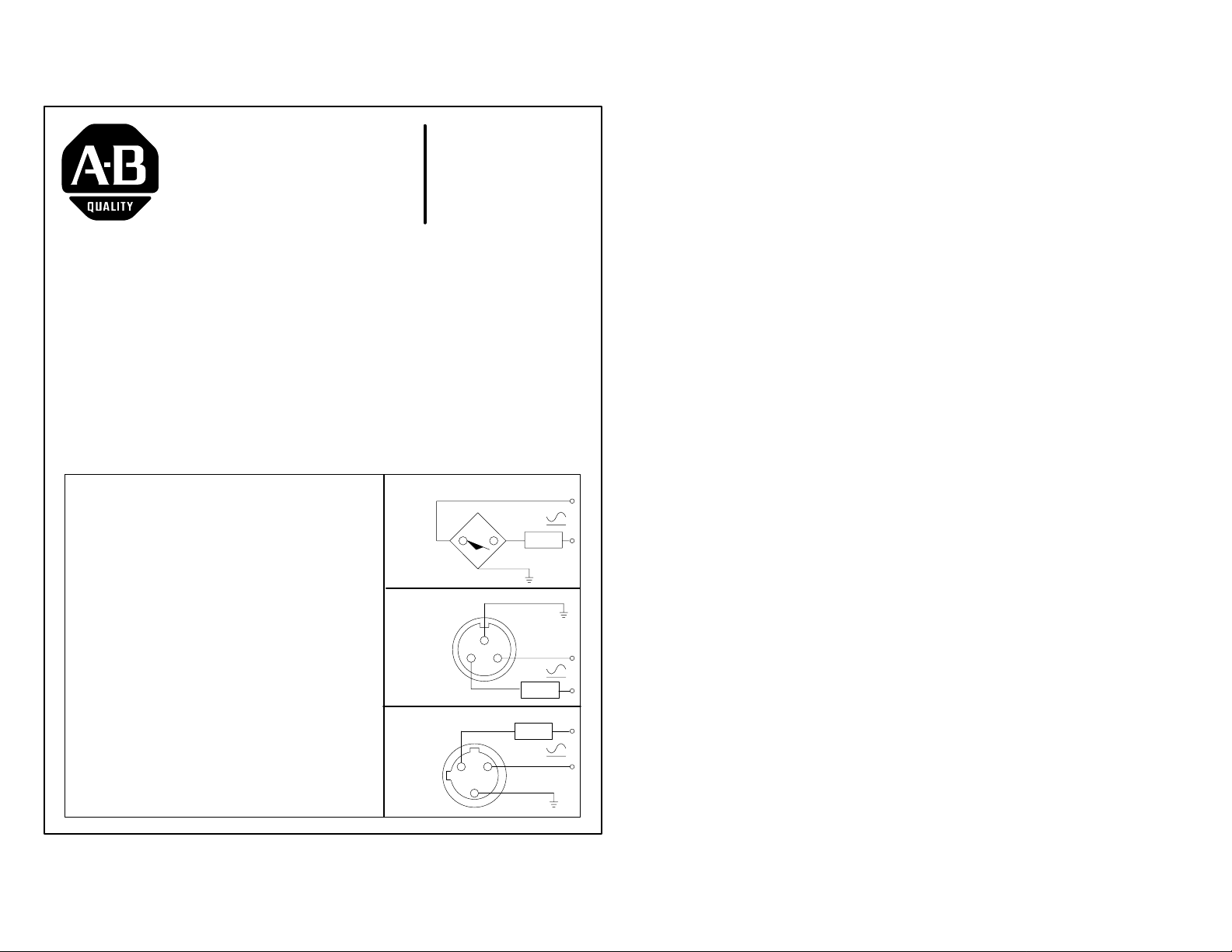
WIRING DIAGRAMS
Cable
Mini Quick
Disconnect
o
C to + 70o C. . . . . . . . . . . .
Micro Quick
Disconnect
WHT
BLK
LOAD
GRN
GROUND
1
2
3
LOAD
LOAD
3
2
1
GROUND
Page 2
INSTALLATION INSTRUCTIONS
CAUTION; Solid state devices can be susceptible to radio frequency (RF) interference, depending on the
frequency of the transmitting source. If RF transmitting equipment is to be used in the vicinity of the solid state
devices, thorough testing should be performed to assure that the transmitter operation is restricted to a safe
operating distance from the control equipment and wiring.
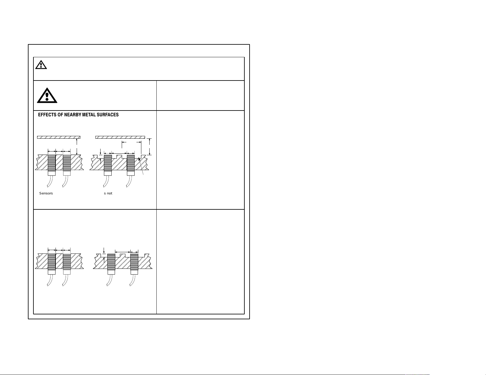
WARNING: Do not let MET AL objects that
are not to be sensed come within three
times the sensing distance of this device.
Unintended process activation may result
in a hazardous condition.
EFFECTS OF NEARBY METAL SURFACES
Metals immediately opposite the sensing face should
be no closer than three times the rated operating
distance of the sensor.
2d
Not shielded
≥3d
d
Metal free
Shielded
3 Sn
d
d
Sensors not embedded in metal
ddd
Sensors embedded in metal
Sn = rated operating distance d = diameter of sensing surface
SPACING BETWEEN SENSORS
When installing side by side, the minimum spacing
distance should be maintained. When mounting face
to face, use two times the diameter.
ddd
Shielded
Sensors embedded in metal
d = diameter of sensing surface
d
Sensors not embedded in metal
2d d
Not shielded
IMPORTANT: Save these instructions for
future use. For additional information and
proper operating guidance, refer to the
Allen-Bradley Proximity Catalog 871-1.2 or
the product data sheet 871TM-2.0
SENSING DISTANCE
The standard target is a square of mild steel
(ST37), 1mm thick. The side of the square
is equal to the diameter of the sensor or
three times the sensing distance, whichever
is larger. Targets smaller than standard size
may shorten the sensing distance. Targets
3 Sn
larger than standard may lengthen the
sensing distance.
CORRECTION FACTORS
To determine the sensing distance for
materials other than the standard mild steel,
multiply the sensing distance by the factor
zone
given below:
Steel 1.0
Stainless Steel 0.9 to 1.0
Brass 0.3 to 0.5
Aluminum 0.1 to 0.4
Aluminum ≤.012 thick 0.9 to 1.1
Copper 0.4 to 0.6
SERIES CONNECTED SWITCHES
When connected in series, the operating
load voltage must be less than or equal to
the minimum supply voltage, minus the
voltage drops across the proximity switches
connected in series. The load will energize
when the connected outputs of all proximity
switches are energized.
PARALLEL CONNECTED SWITCHES
To determine the maximum number of
switches for an application, the sum of the
maximum OFF-state currents of the
switches connected in parallel must be less
than the maximum OFF-state current of the
load device. The load will be energized when
the output of any proximity switch energizes.
NOTE: Parallel operation of switches does
not provide higher load current capability
and may generate a false pulse" under
certain conditions.
 Loading...