

Page 1
BULLETIN
871P
INDUCTIVE
PROXIMITY
SENSOR
133–551(C)
Load Current ≤ 300mA. . . . . . . . . . . . . . . .
Leakage Current ≤ 1.7mA at 132 VAC. . . . . . . . . . . . .
Operating Voltage 24–250 VAC. . . . . . . . . . . .
Voltage Drop ≤ 11 V. . . . . . . . . . . . . . . .
Hysteresis 20% Typical. . . . . . . . . . . . . . . . . . .
Transient Noise Protection INCORPORATED. . . .
Enclosure NEMA 1, 2, 3, 4, 12, 13. . . . . . . . . . . . . . . . . . .
Barrel Plastic. . . . . . . . . . . . . . . . . . . . . . .
Cable Version 2 Meter (6.5 ft.), 2 Conductor. . . . . . . . . . . . . . . .
LED Red: Output Energized. . . . . . . . . . . . . . . . . . . . . . . .
Temperature (Operating) –25
IP67 IEC 529
(–13
o
C to + 55o C. . . . . .
o
F to + 131o F)
WIRING DIAGRAMSPECIFICATIONS
Load can be switched to brown wire
BLACK
BLUE
LOAD
Page 2
INSTALLATION INSTRUCTIONS
133–551(C)
CAUTION; Solid state devices can be susceptible to radio frequency (RF) interference, depending on the
frequency of the transmitting source. If RF transmitting equipment is to be used in the vicinity of the solid
state devices, thorough testing should be performed to assure that the transmitter operation is restricted
to a safe operating distance from the control equipment and wiring.
WARNING: Do not let METAL objects
that are not to be sensed come within
three times the sensing distance of this
device. Unintended process activation
may result in a hazardous condition.
IMPORTANT: Save these instructions for
future use. For additional information and
proper operating guidance, refer to the
Allen-Bradley Proximity Catalog 871-1.2 or
the product data sheet.
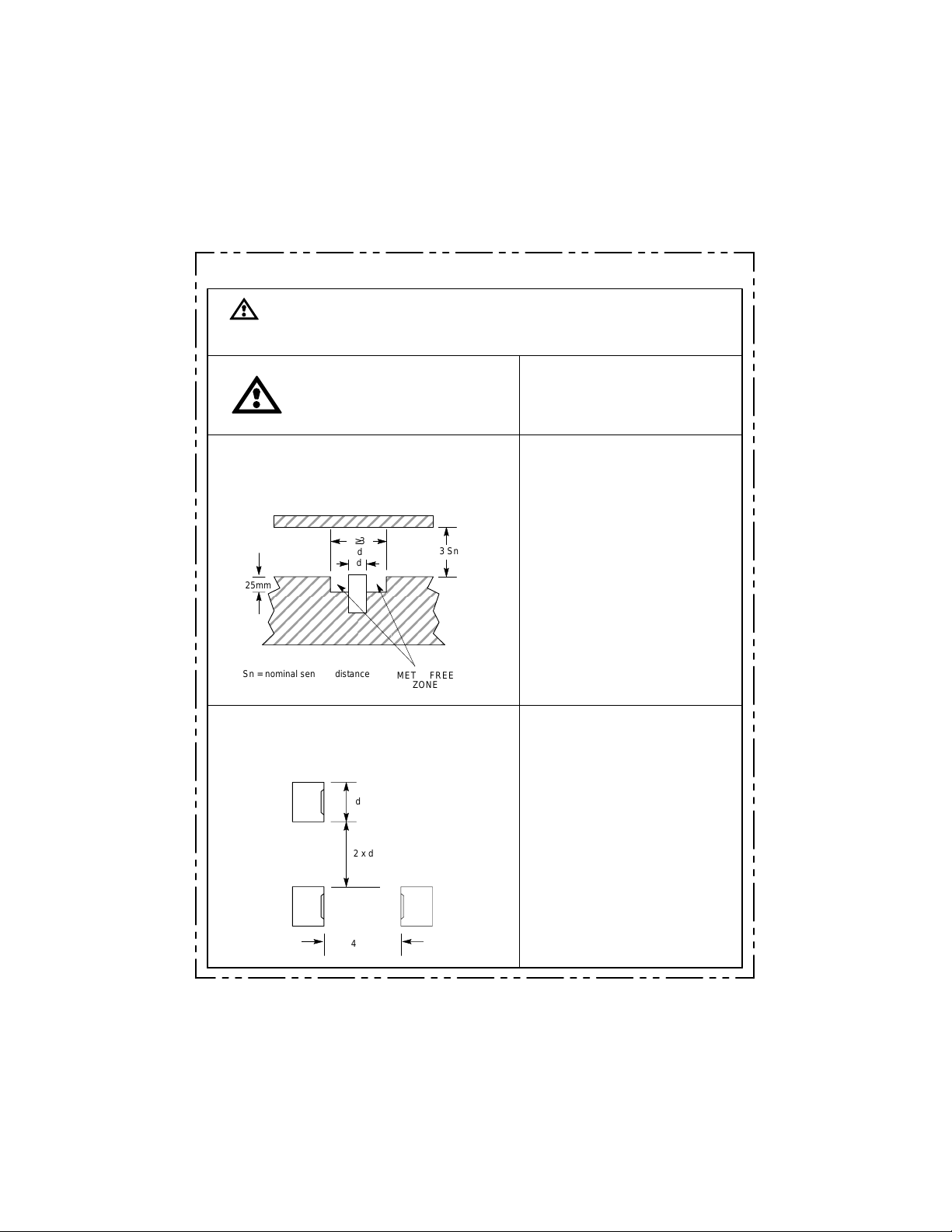
EFFECTS OF NEARBY METAL SURFACES
Metals immediately opposite the sensing face
should be no closer than three times the rated
operating distance of the sensor.
≥3
d
d
25mm
Sn = nominal sensing distance
3 Sn
METAL FREE
ZONE
SPACING BETWEEN SENSORS
When installing side by side, the minimum spacing
distance should be maintained. When mounting face
to face, use two times the diameter.
d
2 x d
4 x d
SENSING DISTANCE
The standard target is a square of mild steel
(ST37), 1mm thick. The side of the square is
equal to the diameter of the sensor. Targets
smaller than standard size may shorten the
sensing distance. Targets larger than
standard may lengthen the sensing distance.
CORRECTION FACTORS
To determine the sensing distance
for materials other than the standard
mild steel, multiply the sensing
distance by the factor given below:
Steel 1.0. . . . . . . . . . . . . . . . .
Stainless Steel 0.7 to 0.8. . . . . . . . .
Brass 0.4 to 0.5. . . . . . . . . . . . . . . . .
Aluminum 0.3 to 0.4. . . . . . . . . . . . .
Copper 0.3 to 0.4. . . . . . . . . . . . . . .
SERIES CONNECTED SWITCHES
When connected in series, the operating
load voltage must be less than or equal to
the minimum supply voltage, minus the
voltage drops across the proximity switches
connected in series. The load will energize
when the connected outputs of all proximity
switches are energized.
PARALLEL CONNECTED SWITCHES
To determine the maximum number of
switches for an application, the sum of the
maximum OFF-state currents of the
switches connected in parallel must be less
than the maximum OFF-state current of the
load device. The load will be energized when
the output of any proximity switch energizes.
NOTE: Parallel operation of switches does
not provide higher load current capability.
 Loading...