

Page 1
INSTALLATION INSTRUCTIONS
Programmable
BULLETIN 871L AC/DC LIMIT SWITCH STYLE INDUCTIVE PROXIMITY SENSOR
Head Size
40
Nominal Sensing
Distance
mm (inches)
20 (0.79) Y
40 (1.57) N
Shielded
Output
Configuration
Programmable
N.O. or N.C.
Switching
Frequency
(Hz)
15
Part Number
Conduit Opening Mini Style QD Micro Style QD
871L-B20E40-T2 871L-B20E40-N3 871L-B20E40-R3
871L-B40E40-T2 871L-B40E40-N3 871L-B40E40-R3
Specifications
Load Current 400mA
Minimum Load Current 2mA
Leakage Current
Operating Voltage 20Ć250V AC/DC
Voltage Drop
Repeatability
Hysteresis
False Pulse Protection Incorporated
Transient Noise Protection Incorporated
Short Circuit Protection Incorporated
Overload Protection Incorporated
Enclosure NEMA 3, 4, 6, 12 and 13
Connections Conduit Opening: 1/2Ć14 NPT internal
2 LEDs Green: Power (Blinks in SCP/Overload)
Operating Temperature
Shock and Vibration 30G, 10Ć55Hz
≤2mA
≤5V
≤5%
≤20%
IP67 (IEC 529) Polyloy
Quick Disconnect: 3Ćpin mini style
Orange: Output Energized
-25°C to +70°C (-13°F to +158°F)
thread with screw
terminals
3Ćpin micro style
Accessories
Optional Mating Cables
Part Number
871A-CS3-R2 2M (6.56 ft.) 3Ćpin, microĆstyle straight
871A-CS3-R4 4M (13.1 ft.) 3Ćpin, microĆstyle straight
871A-CS3-R5 5M (16.4 ft.) 3Ćpin, microĆstyle straight
871A-CS3-N1 1M (3.28 ft.) 3Ćpin, miniĆstyle straight
871A-CS3-N2 2M (6.56 ft.) 3Ćpin, miniĆstyle straight
871A-CS3-N4 4M (13.1 ft.) 3Ćpin, miniĆstyle straight
871A-CRL3-N1 1M (3.28 ft.) 3Ćpin, miniĆstyle right angle LED
871A-CRL3-N2 2M (6.56 ft.) 3Ćpin, miniĆstyle right angle LED
871A-CRL3-N4 4M (13.1 ft.) 3Ćpin, miniĆstyle right angle LED
Length Description
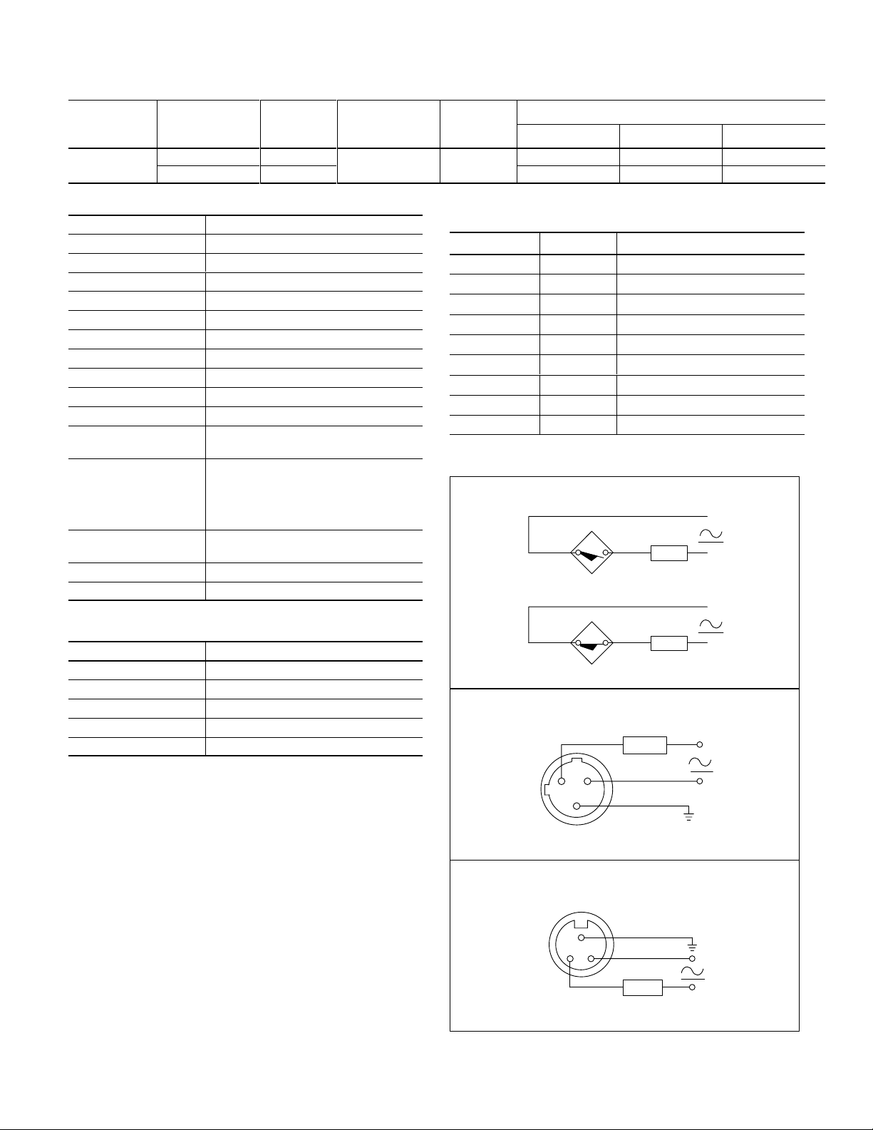
Wiring Diagrams
Conduit Opening
Normally Open
T1
Normally Closed
T2
Load
Correction Factors
Target Material
Steel 1.0
Stainless Steel 0.90
Brass 0.50
Aluminum 0.45
Copper 0.40
Correction Factor
Description
Bulletin 871L inductive proximity sensors are self-contained,
general purpose, solid state devices. These devices are
designed for most industrial applications where it is required to
sense the presence of metal objects (ferrous and non-ferrous)
without touching them.
The 871L limit switch style provides mounting
interchangeability, easy to wire terminations, rugged
construction, and superior sealing. The 25 (twenty-five)
position sensing head allows for twenty-four side views and
one top view.
Diagnostics
Green on indicates power on.
Orange on indicates output is energized.
Green flashing indicates short circuit or overload.
Micro QD
Mini QD
T1
Note: Load can be switched to terminal 1.
Normally Open or Normally Closed
3
1
Note: Load can be switched to pin 2.
Normally Open or Normally Closed
1
Note: Load can be switched to pin 3.
T2
Load
Load
2
32
Ground
Ground
Load
Page 2
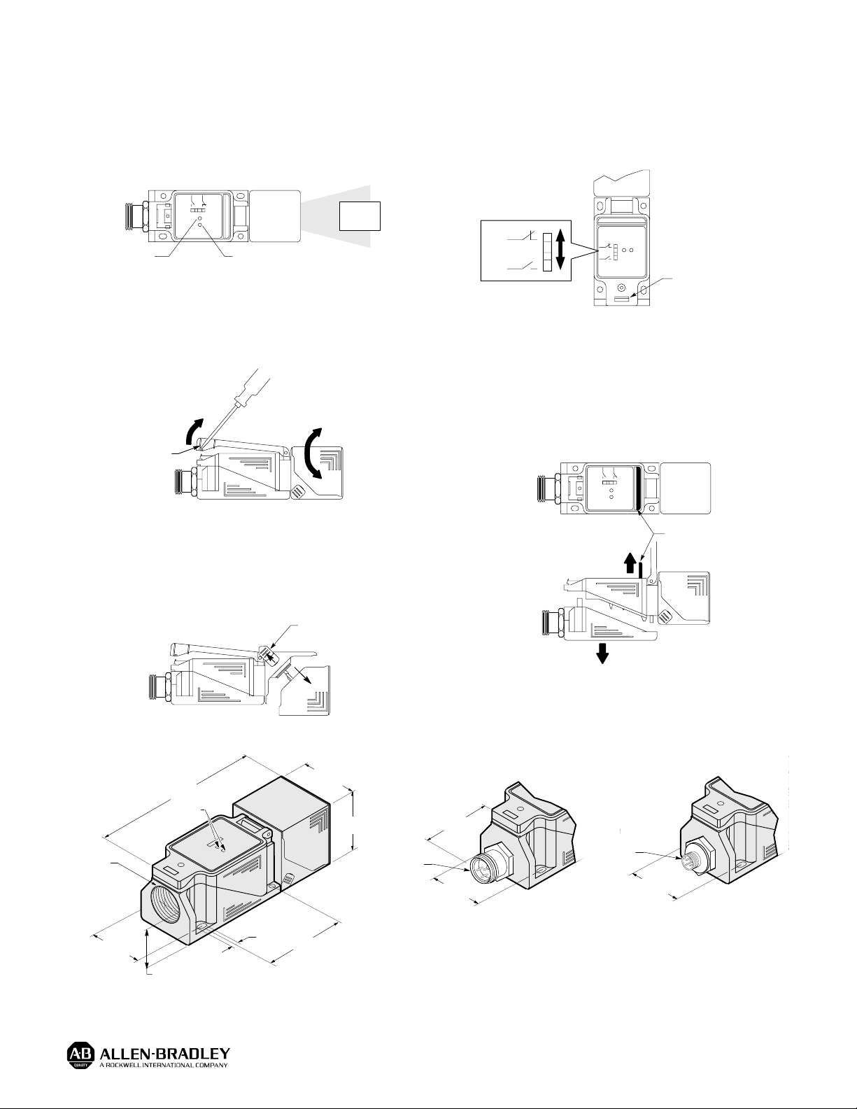
Installation
Alignment
When power is applied to the sensor, the green (power on)
indicator will turn on. Visually sight the sensing head at the
object to be detected until the orange (output energized)
indicator turns on when the sensor is set for normally open or
turns off when the control is set for normally closed.
Sensor (Top View)
Target
Orange Green
Output Energized Power On
Rotation of Sensing Head
Insert screwdriver in slot located at the bottom of the clear
plastic cover, gently pull upward. This will release the locking
mechanism and enable rotation of the sensing head. The
sensing head can be rotated in 15° increments.
Locking
Mechanism
Selecting Output
Insert screwdriver in slot located at the bottom of the clear
plastic cover, gently pull upward. This will release the locking
clip and allow access to the selectable output. The switch is
supplied in the normally open position. Simply move the
switch to the normally closed position; re-wiring is not
necessary.
(N.C.)
(N.O.)
Locking
Mechanism
Wiring of Terminal Base
Unlock the plastic cover to access the black bar. To release
the base, simply lift the black bar located inside the body . This
will release the locking mechanism. Gently pull the terminal
base from the sensor body to access the screw terminals.
Note: All external wiring should conform to the National Electric
Code and applicable local codes. See wiring diagrams
for external connections.
Sensing Head Position
Unlock plastic cover and rotate sensing head so that clips are
in the top position. To change from side sensing to top
sensing, simply snap back the two clips located on either side
of the sensing head. Release and rotate the head to the top or
side position, return clips to locking position to secure head.
Clips Must be in
Top Posititon
Dimensions — mm (inches)
Conduit Style
40.0
60.0
(2.36)
(1.57)
40.0
(1.57)
7/8Ć16UNĆ2A
Conduit
Entrance
1/2-14 NPT
30.0
(1.18)
15.9
(0.63)
120.0
(4.72)
LEDs
7.3
(0.29)
Mini Style
Quick-Disconnect
17.0
(0.67)
30.0
(1.18)
M12 x 1
Black Bar
Micro Style
Quick-Disconnect
30.0
(1.18)
Publication 46803–054–01(A)
November 1994
Printed in USA
 Loading...