

Page 1
871F 2-wire AC/DC Proximity Sensors
IMPORTANT: SAVE THESE INSTRUCTIONS FOR FUTURE USE.
Suitable for use in Class 1, Division 2,
Groups A, B, C, D or nonhazardous
locations only.
Explosion hazard: substitution of
components may impair suitability for
Class 1, Division 2.
Explosion hazard: Do not disconnect
equipment unless power has been
switched off or the area is known to be
nonhazardous.
WARNING
871F for Hazardous Locations
Models covered:
Conduit 1/2-14 NPT
871F-R50N80-T2
871F-K65N80-T2
Conduit PG13.5
871F-R50N80-Q2
871F-K65N80-Q2
Installation Instructions
General Specifications
Electrical
Load Current ≤ 100 mA
Minimum Load Current 5 mA
Leakage Current
Operating Voltage 20…250V AC/DC
Voltage Drop ≤ 10V
Repeatability ≤ 5%
Hysteresis ≤ 10% typical
False Pulse Protection Incorporated
Transient Noise Protection Incorporated
Short Circuit Protection Incorporated
Overload Protection Incorporated
Environmental
Certifications
Enclosure
Mechanical
Housing material
Connections Conduit Opening:1/2-14NPT thread, PG 13.5
LEDs Green: Power
Operating Temperature [C (F)] -25…+70° (-13…+158°)
Shock 30 g, 11 ms
Vibration 55 Hz, 1 mm amplitude, 3 planes
≤ 1.8 mA @ 24V
≤ 1.8 mA @ 120V
≤ 2.0 mA @ 250V
cULus Listed, and CE Marked for all
applicable all directives
NEMA 1, 2, 3, 4, 6, 6P, 12 and 13, IP67
(IEC529)
1200 psi (8270 kPa) washdown
Division 2 Class I: Groups A, B, C, D
®
Valox
thread
Orange: Output Energized
Page 2
Power, Control and Information Solutions Headquarters
Americas: Rockwell Automation, 1201 South Second Street, Milwaukee, WI 53204-2496 USA, Tel: (1) 414.382.2000, Fax: (1) 414.382.4444
Europe/Middle East/Africa: Rockwell Automation NV, Pegasus Park, De Kleetlaan 12a, 1831 Diegem, Belgium, Tel: (32) 2 663 0600, Fax: (32) 2 663 0640
Asia Pacic: Rockwell Automation, Level 14, Core F, Cyberport 3, 100 Cyberport Road, Hong Kong, Tel: (852) 2887 4788, Fax: (852) 2508 1846
www.rockwel lautomation.com
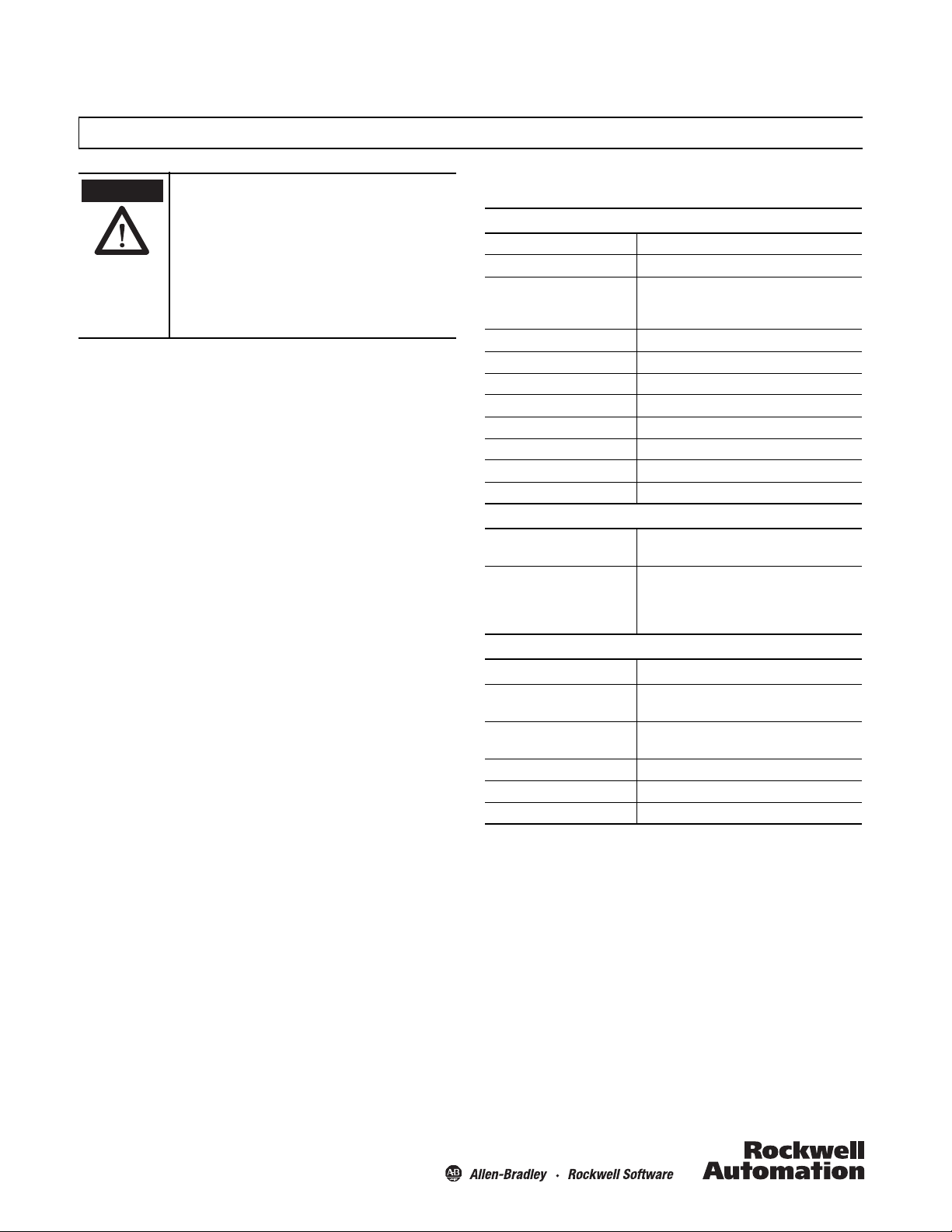
Wiring Diagram
T2 T3
Load
Note: Load can be switched to terminal 2.
LEDs
65.0
(2.56)
44.0 (1.57)
83.0
(3.27)
65.0
(2.56)
6.0
(0.24)
94.0 (3.70)
Conduit opening
1/2 inch internal
thread
LEDs
44.0 (1.57)
94.0 (3.70)
6.0
(0.24)
83.0
(3.27)
65.0
(2.56)
65.0
(2.56)
Conduit opening
PG13.5 internal
thread
Active Face
dd
Mounting Space
Conduit Style 1/2-14 NPT, PG13.5 Normally Open
Approximate Dimensions [mm (in.)]
Conduit Style 1/2-14 NPT
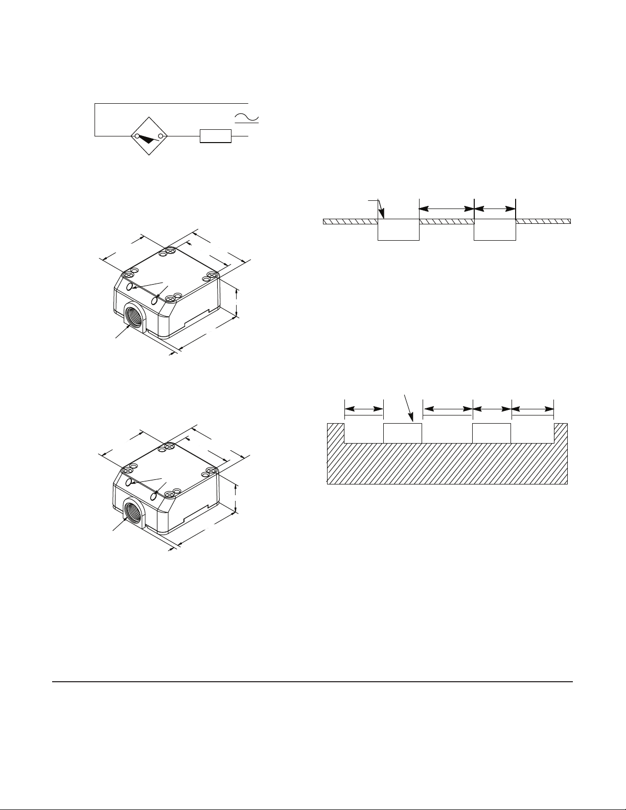
Spacing Between Shielded Sensors (flushmountable) and Nearby Metal Surfaces
Shielded proximity sensors allow the electro-magnetic field to be concentrated to the front of the
sensor face. Shielded construction allows the
proximity to be mounted flush in surrounding metal
without causing a false trigger.
Flat Pack Style (871F)
Spacing Between Unshielded Sensors (nonflushmountable) and Nearby Metal Surfaces
Longer sensing distances can be obtained by
using an unshielded sensor. Unshielded proximity
sensors require a metal-free zone around the
sensing face. Metal immediately opposite the
sensing face should be no closer than three times
the rated nominal sensing distance of the sensor.
Suggested mounting: M5 or SAE#10 cap screw should be
used with a split lock washer to install the unit.
Conduit Style PG13.5
Flat Pack Style (871F)
Active Face
d4d
dd
Copyright © 2012 Rockwell Automation, Inc. All Rights Reserved. PN-141168
10000243172 Ver 00
March 2012
 Loading...