

Page 1

865 Differential Protection Relay
For Motor, Transformer and Generator Dierential Protection
Bulletin 865, Series A
User Manual
Page 2
Solid-state equipment has operational characteristics differing from those of electro-
Important User Information
mechanical equipment. Safety Guidelines for the Application, Installation and
Maintenance of Solid-State Controls (Publication SGI-1.1 available from your local
Rockwell Automation sales office or online at http://literature.rockwellautomation.com)
describes some important differences between solid-state equipment and hard-wired
electromechanical devices. Because of this difference, and also because of the wide variety of
uses for solid-state equipment, all persons responsible for applying this equipment must
satisfy themselves that each intended application of this equipment is acceptable.
In no event will Rockwell Automation, Inc. be responsible or liable for any indirect or
consequential damages resulting from the use or application of this equipment.
The examples and diagrams in this manual are included solely for illustrative purposes.
Because of the many variables and requirements associated with any particular installation,
Rockwell Automation, Inc. cannot assume responsibility or liability for actual use, based on
the examples and diagrams.
No patent liability is assumed by Rockwell Automation, Inc. with respect to use of
information, circuits, equipment, or software described in this manual.
Reproduction of the contents of this manual, in whole or in part, without written
permission of Rockwell Automation, Inc. is prohibited.
Throughout this manual, when necessary we use notes to make you aware of safety
considerations.
W A R N I N GW A R N I N G
Identifies information about practices or circumstances that can
cause an explosion in a hazardous environment, which may lead
to personal injury or death, property damage, or economic loss.
I M P O R T A N TI M P O R T A N T
Identifies information that is critical for successful application
and understanding of the product.
A T T E N T I O NA T T E N T I O N
Identifies information about practices or circumstances that can
lead to personal injury or death, property damage, or economic
loss. Attentions help you identify a hazard, avoid a hazard, and
recognize the consequences.
S H O C K H A Z A R DS H O C K H A Z A R D
Labels may be on or inside the equipment (for example, drive or
motor) to alert people that dangerous voltage may be present.
B U R N H A Z A R DB U R N H A Z A R D
Labels may be on or inside the equipment (for example, drive or
motor) to alert people that surfaces may reach dangerous
temperatures.
Page 3

Table of Contents
Chapter 1 Overview Introduction ............................................................................. 1-1
User Interface ...........................................................................1-3
Operating Safety ..................................................................... 1-3
Chapter 2 Relay Front Panel ....................................................................2-1
Display ............................................................................. 2-1
Menu Navigation and Pointers ......................................... 2-3
Keypad ............................................................................. 2-3
Operation Indicators ......................................................... 2-4
Resetting Latched Indicators and Output Relays ............. 2-5
Adjusting Display Contrast .............................................. 2-5
Local Panel Options ................................................................ 2-5
Navigating in Menus ........................................................ 2-5
Main Menu ....................................................................... 2-7
Menu Structure of Protection Functions .......................... 2-9
Setting Groups ................................................................ 2-12
Fault Logs ....................................................................... 2-13
Operating Levels ............................................................ 2-14
Opening Access .............................................................. 2-15
Password Handling ......................................................... 2-15
Operating Measures .............................................................. 2-16
Control Functions ........................................................... 2-16
Measured Data ............................................................... 2-17
Reading Event Register .................................................. 2-18
Forced Control (Force) ................................................... 2-19
Configuration and Parameter Setting .................................... 2-20
Parameter Setting ........................................................... 2-21
Setting Range Limits ...................................................... 2-22
Disturbance Recorder Menu DR .................................... 2-23
Configuring Digital Inputs DI ........................................ 2-23
Configuring Digital Outputs DO .................................... 2-24
Protection Menu Prot ..................................................... 2-24
Configuration Menu CONF ........................................... 2-25
Protocol Menu Bus ......................................................... 2-27
Single Line Diagram Editing .......................................... 2-30
SetPointPS PC Software ....................................................... 2-31
Local Panel User
Interface
Chapter 3 Protection Functions Maximum Number of Protection Stages ................................ 3-1
Protection Functions ............................................................... 3-1
General Features of Protection Stages .................................... 3-1
Setting Groups .................................................................. 3-1
Forcing Start or Trip Condition for Testing ..................... 3-2
Forcing Start or Trip Condition for Testing Purposes ...... 3-2
Start and Trip Signals ....................................................... 3-2
Output Matrix ................................................................... 3-2
Blocking ........................................................................... 3-3
Main Relay Features ................................................................1-1
865-UM001A-EN-P – July 2009
Page 4

ii Table of Contents
Retardation Time .............................................................. 3-3
Chapter 3 Protection Functions
Reset Time (Release Time) .............................................. 3-4
(cont.)
Hysteresis or Dead Band .................................................. 3-5
Differential Overcurrent Protection ΔI> (87) ......................... 3-6
Parameters of the Differential Overcurrent Stages ......... 3-10
Overcurrent Protection I> (50/51) ........................................ 3-11
Two Independent Stages ................................................ 3-11
Inverse Operation Time .................................................. 3-11
Inverse Time Limitation ................................................. 3-11
Setting Groups ................................................................ 3-11
Recorded Values of the Latest Eight Faults ................... 3-14
Current Unbalance Protection I
>, I’2 (46) ........................... 3-15
2
Inverse Delay ................................................................. 3-15
More Stages (Definite Time Delay only) ....................... 3-15
Setting Groups ................................................................ 3-15
Recorded Values of the Latest Eight Faults ................... 3-17
Earth Fault Protection I
> (50N/51N) ................................... 3-17
0
Input Signal Selection .................................................... 3-18
Intermittent Earth Fault Detection .................................. 3-18
Four Independent Undirectional Earth Fault
Overcurrent Stages ................................................... 3-18
Inverse Operation Time (I
> stage only) ........................ 3-19
0
Inverse Time Limitation ................................................. 3-19
Setting Groups ................................................................ 3-19
Recorded Values of the Latest Eight Faults ................... 3-22
Thermal Overload Protection T> (49) .................................. 3-22
Thermal Model ............................................................... 3-22
Time Constant for Cooling Situation ............................. 3-23
Heat Capacitance, Service Factor and Ambient Temp. ... 3-23
Example of a Behavior of the Thermal Model ............... 3-24
Initial Temperature Rise after Restart ............................ 3-24
Alarm Function .............................................................. 3-24
Circuit-Breaker Failure Protection CBFP (50BF) ................ 3-26
Recorded Values of the Latest Eight Faults .......................... 3-27
Arc Fault Protection (50ARC/50NARC) - Optional ............ 3-28
Three Stages for Arc Faults ............................................ 3-28
Light Channel Selection ................................................. 3-28
Binary Input ................................................................... 3-28
Binary Output ................................................................. 3-29
Delayed Light Indication Signal .................................... 3-29
Pick Up Scaling .............................................................. 3-29
Recorded Values of the Latest Eight Faults ................... 3-30
Programmable Stages (99) .................................................... 3-31
Available Signals to be Supervised by the
Programmable Stages .............................................. 3-31
Eight Independent Stages ............................................... 3-31
Setting Groups ................................................................ 3-31
Recorded Values of the Latest Eight Faults ................... 3-32
865-UM001A-EN-P – July 2009
Page 5

Table of Contents iii
Inverse Time Operation ........................................................ 3-33
Chapter 3 Protection Functions
Stage Specific Inverse Delay .......................................... 3-33
(cont.)
Operation Modes ............................................................ 3-33
Local Panel Graph .......................................................... 3-33
Inverse Time Setting Error Signal .................................. 3-34
Limitation ....................................................................... 3-34
Standard Inverse Delays IEC, IEEE, IEEE2, RI ............ 3-35
IEC Inverse Time Operation .................................... 3-36
IEEE/ANSI Inverse Time Operation ....................... 3-38
IEEE2 Inverse Time Operation ............................... 3-42
RI and RXIDG type Inverse Time Operation .......... 3-43
Free Parametrisation using IEC, IEEE and IEEE2
Equations ................................................................. 3-45
Programmable Inverse Time Curves .............................. 3-46
Inverse Time Setting Error Signal .................................. 3-47
Limitations ..................................................................... 3-47
Chapter 4 Supporting Functions Event Log ................................................................................4-1
Event Enabling/Masking .................................................. 4-1
Event Buffer Overflow ..................................................... 4-2
Disturbance Recorder ............................................................. 4-2
Triggering the Recorder ................................................... 4-2
Reading Recordings ......................................................... 4-2
Number of Channels ........................................................ 4-3
Available Channels .......................................................... 4-3
Current Transformer Supervision ........................................... 4-5
Circuit Breaker Condition Monitoring ................................... 4-6
Breaker Curve and its Approximation ............................. 4-6
Setting Alarm Points ........................................................ 4-7
Clearing “Operations Left” Counters ............................... 4-8
Operation Counters to Monitor the Wearing .................... 4-8
Logarithmic Interpolation ................................................ 4-8
Example of the Logarithmic Interpolation ....................... 4-9
Example of Operation Counter Decrementing ................. 4-9
System Clock and Synchronization .......................................4-11
Adapting Auto Adjust .................................................... 4-11
Time Drift Correction Without External Sync ............... 4-11
System Clock Parameters ..................................................... 4-13
Running Hour Counter ......................................................... 4-14
Timers ................................................................................... 4-14
Combined Overcurrent Status ............................................... 4-16
Self-Supervision ................................................................... 4-17
865-UM001A-EN-P – July 2009
Page 6

iv Table of Contents
Chapter 5 Measurement Functions Measurement Accuracy ...........................................................5-1
Harmonics and Total Harmonic Distortion (THD) ................. 5-2
RMS Values ............................................................................ 5-3
RMS Currents ................................................................... 5-3
Demand Values ....................................................................... 5-3
Maximum and Maximum Values ........................................... 5-3
Maximum Values of the last 31 days and 12 months ............. 5-4
Primary, Secondary and per unit Scaling ................................ 5-4
Current Scaling ................................................................. 5-4
Chapter 6 Control Functions Output Relays ..........................................................................6-1
Digital Inputs .......................................................................... 6-2
Virtual Inputs and Outputs ...................................................... 6-3
Output Matrix ......................................................................... 6-4
Blocking Matrix ...................................................................... 6-5
Controllable Objects ............................................................... 6-5
Object States ..................................................................... 6-6
Basic Settings for Controllable Objects ........................... 6-6
Output Signals of Controllable Objects ........................... 6-6
Settings for Read-only Objects ........................................ 6-7
Controlling with DI (Firmware version >= 5.53) ............. 6-7
Local/Remote Selection ................................................... 6-7
Logic Functions ...................................................................... 6-8
Chapter 7 Communications Communication Ports ..............................................................7-1
Local Port X4 ................................................................... 7-2
Remote Port X5 ................................................................ 7-4
Extension Port X4 ............................................................ 7-6
Optional Inbuilt Ethernet Port .......................................... 7-7
Optional 61850 Interface .................................................. 7-7
Communication Protocols ...................................................... 7-8
PC Communication .......................................................... 7-8
Modbus TCP and Modbus RTU........................................ 7-8
Probibus DP ..................................................................... 7-9
SPA-bus .......................................................................... 7-10
IEC 60870-5-103 ............................................................ 7-11
DNP 3.0 .......................................................................... 7-13
IEC 60870-5-101 .............................................................7-14
TCP/IP ............................................................................ 7-16
External I/O (Modbus RTU master) ............................... 7-16
IEC 61850 ...................................................................... 7-16
865-UM001A-EN-P – July 2009
Page 7

Table of Contents v
Chapter 8 Applications Restricted Earth Fault Protection .............................................8-1
Restricted Earth Fault Protection for a Transformer
With Neutral Connection ................................................. 8-2
CT Requirements ............................................................. 8-2
Calculating the Stabilizing Resistance R
, VDR Value,
S
and Actual Sensitivity ................................................ 8-3
Value of Stabilizing Resistor R
...................................... 8-3
S
Voltage Limitation ........................................................... 8-3
Actual Operating Sensitivity ............................................ 8-4
Current Transformer Selection ............................................... 8-5
CT Classification according IEC 60044-1, 1996 ............. 8-5
CT Requirement for Protection ........................................ 8-8
Protection of a Dyn11 Transformer ...................................... 8-11
Protection of a YNd11 Transformer ..................................... 8-13
Protection of Generator and Block Transformer .................. 8-14
Application Example of Differential Protection
using Allen-Bradley 865 Relay ...................................... 8-15
Trip Circuit Supervision ...................................................... 8-16
Chapter 9 Connections Rear Panel View ......................................................................9-1
Auxiliary Voltage ................................................................... 9-5
Serial Communication Connectors ......................................... 9-5
Front Panel Connector ...................................................... 9-5
Rear Panel Connector X5 (REMOTE) ............................. 9-5
X4 Rear Panel Connector (Local RS232 and
Extension RS485 ports) ............................................. 9-7
Optional Two-Channel Arc Protection Card .......................... 9-8
Optional Digital I/O Card (DI19/DI20) .................................. 9-8
Connection Examples ............................................................. 9-9
865-UM001A-EN-P – July 2009
Page 8

vi Table of Contents
Chapter 10 Technical Data Connections .......................................................................... 10-1
Measuring Circuitry ....................................................... 10-1
Auxiliary Voltage ........................................................... 10-1
Digital Inputs .................................................................. 10-2
Trip Contacts .................................................................. 10-2
Alarm Contacts ............................................................... 10-2
Local Serial Communication Port .................................. 10-3
Remote Control Connection ........................................... 10-3
Arc Protection Interface (Option) .................................. 10-3
Tests and Environmental Conditions .................................... 10-4
Disturbance Tests ........................................................... 10-4
Test Voltages .................................................................. 10-4
Mechanical Tests ............................................................ 10-4
Environmental Conditions .............................................. 10-4
Casing ............................................................................. 10-5
Package .......................................................................... 10-5
Protection Stages .................................................................. 10-5
Differential Protection .................................................... 10-5
Differential Overcurrent Stage ΔI> (87) .................. 10-5
Differential Overcurrent Stage ΔI>> (87) ............... 10-5
Non-Directional Current Protection ............................... 10-6
Overcurrent Stage I>, I’> (50/51) ............................ 10-6
Overcurrent Stage I>> and I’>> (50/51) .................. 10-6
Thermal Overload Stage T> (49) ............................. 10-7
Unbalance Stage I
Earth Fault Stage I
Earth Fault Stage I
>, I’2> (46) ................................. 10-7
2
> (50N/51N) ............................. 10-8
0
>>, I0>>>, I0>>>> (50N/51N) .. 10-8
0
Circuit-breaker Failure Protection .................................. 10-9
Arc Fault Protection Stages (Option) ............................. 10-9
Arc Protection Stage Arcl> (50AR), Option ........... 10-9
Arc Protection Stage Arcl
Arc Protection Stage Arcl
> (50AR), Option .......... 10-9
0
> (50AR), Option ....... 10-10
02
Supporting Functions ................................................... 10-10
Disturbance Recorder (DR) ................................... 10-10
Chapter 11 List of Abbreviations and Symbols .......................................11-1
Abbreviations and
Symbols
Chapter 12 Installation Mounting Instructions ........................................................... 12-1
865-UM001A-EN-P – July 2009
Page 9

Chapter 1
Overview
Introduction The Allen-Bradley 865 differential protection system includes all the
essential protection functions needed to protect transformers for
distribution networks of utilities, industry, power plants and offshore
applications as well as motor and generator differential protection.
Further, the device includes several programmable functions, such as
thermal and circuit breaker protection and communication protocols
for various protection and communication situations. An optional
arc flash protection feature is also available.
The Allen-Bradley 865 can be used for selective differential
overcurrent, short-circuit protection of generators, transformers
and motors in solidly or impedance earthed power systems. The
relay can also be used for single, two or three-phase overcurrent
and/or sensitive earth fault protection.
The modern technology in association with an extensive self-
supervision system and a reliable construction ensures extremely
high system availability for the Allen-Bradley 865 protection
relay.
Main Relay Features The main features of Allen-Bradley 865 are:
• Fully digital signal handling with a powerful 16-bit
microprocessor, and high measuring accuracy on all the setting
ranges due to an accurate 16-bit A/D conversion technique
• Wide setting ranges for the protection functions, e.g. the earth
fault protection can reach a sensitivity of 0.5%
• The device can be matched to the requirements of the application
by disabling the functions that are not needed
• Flexible control and blocking possibilities due to digital signal
control inputs (DI) and outputs (DO)
• Easy adaptability of the relay to various substations and alarm
systems due to flexible signal-grouping matrix in the relay
• Freely configurable display with six measurement values
865-UM001A-EN-P – July 2009
Page 10

1-2 Overview
Main Features (cont.)
• Freely configurable interlocking schemes with basic logic
functions
• Recording of events and fault values into an event register from
which the data can be read via a keypad and a local HMI or by
means of a PC based SetPointPS user interface
• Latest events and indications are in non-volatile memory.
• Easy configuration, parameter setting and reading of information
via local HMI, or with the SetPointPS programming software
• Easy connection to power plant automation system due to a
versatile serial connection and several available communication
protocols
• Built-in, self-regulating ac/dc converter for auxiliary power
supply from any source within the range from 40 to 865 V dc or
ac. The alternative power supply is for 18 to 36 V dc
• Built-in disturbance recorder for evaluating all the analogue and
digital signals
• Eight (8) programmable stages for alarming or protection
purposes
The Allen-Bradley 865 differential protection relay is ideal for
transformer, motor, generator and short cable (100) differential
protection. The relay features the following protection functions.
Table 1-1 – List of Protection Functions
IEEE/
ANSI code
50/51 3I>, 3I>>, 3I’>, 3I’>> Overcurrent protection
87 ∆I>, ∆I>> Differential overcurrent protection
46 I2>, I’2> Current unbalance protection
49 T> Thermal overload protection
50N/51N
50BF CBFP Circuit-breaker failure protection
99 Prg1...8 Programmable stages
50ARC
50NARC
Further the relay includes a disturbance recorder. Arc protection
is optionally available.
The relay communicates with other systems using common
protocols, such as the Modbus RTU, ModbusTCP, Profibus DP,
Ethernet, DeviceNet, IEC 60870-5-103, SPA bus and DNP 3.0,
IEC 61850 and IEC 60870-5-101.
IEC symbol Function name
>,
I
0
>>,
I
0
I
>>>,
0
>>>>
I
0
ArcI>, ArcI’>
>, ArcI02>
ArcI
01
Earth fault protection
Optional arc fault protection
865-UM001A-EN-P – July 2009
Page 11

Overview 1-3
User Interface
The relay can be controlled in three ways:
• Locally with the push-buttons on the relay front panel
• Locally using a PC connected to the serial port on the front panel
or on the rear panel of the relay (both cannot be used
simultaneously)
• Via remote control over the remote control port on the relay rear
panel.
Operating Safety
A T T E N T I O NA T T E N T I O N
The terminals on the rear panel of the relay may
carry dangerous voltages, even if the auxiliary
voltage is switched off. A live current
transformer secondary circuit must not be
opened. Disconnecting a live circuit may cause
dangerous voltages! Any operational measures
must be carried out according to national and
local handling directives and instructions.
Carefully read through all operation instructions before any
operational measures are carried out.
865-UM001A-EN-P – July 2009
Page 12

1-4 Overview
865-UM001A-EN-P – July 2009
Page 13

Chapter 2
Local Panel User Interface
Relay Front Panel The figure below shows, as an example, the front panel of the
Allen-Bradley 865 relay and the location of the user interface
elements used for local control.
Figure 2.1 – Front Panel of Allen-Bradley 865 Relay
1. LCD dot matrix display
2. Keypad
3. LED indicators
4. RS 232 serial communication port for PC
Display
The relay is provided with a backlit 128x64 LCD dot matrix
display. The display enables showing 21 characters in one row
and eight rows at the same time. The display has two different
purposes: one is to show the single line diagram of the relay with
the object status, measurement values, identification etc. (Figure
2.2). The other purpose is to show the configuration and
parameter setting values of the relay (Figure 2.3).
865-UM001A-EN-P – July 2009
Page 14
2-2 Local Panel User Interface
4
5
K00 0 6
2
Q4
Q1
Q0
Q3
Q9
3
AR : 1
50.02 Hz
L
6
1
7
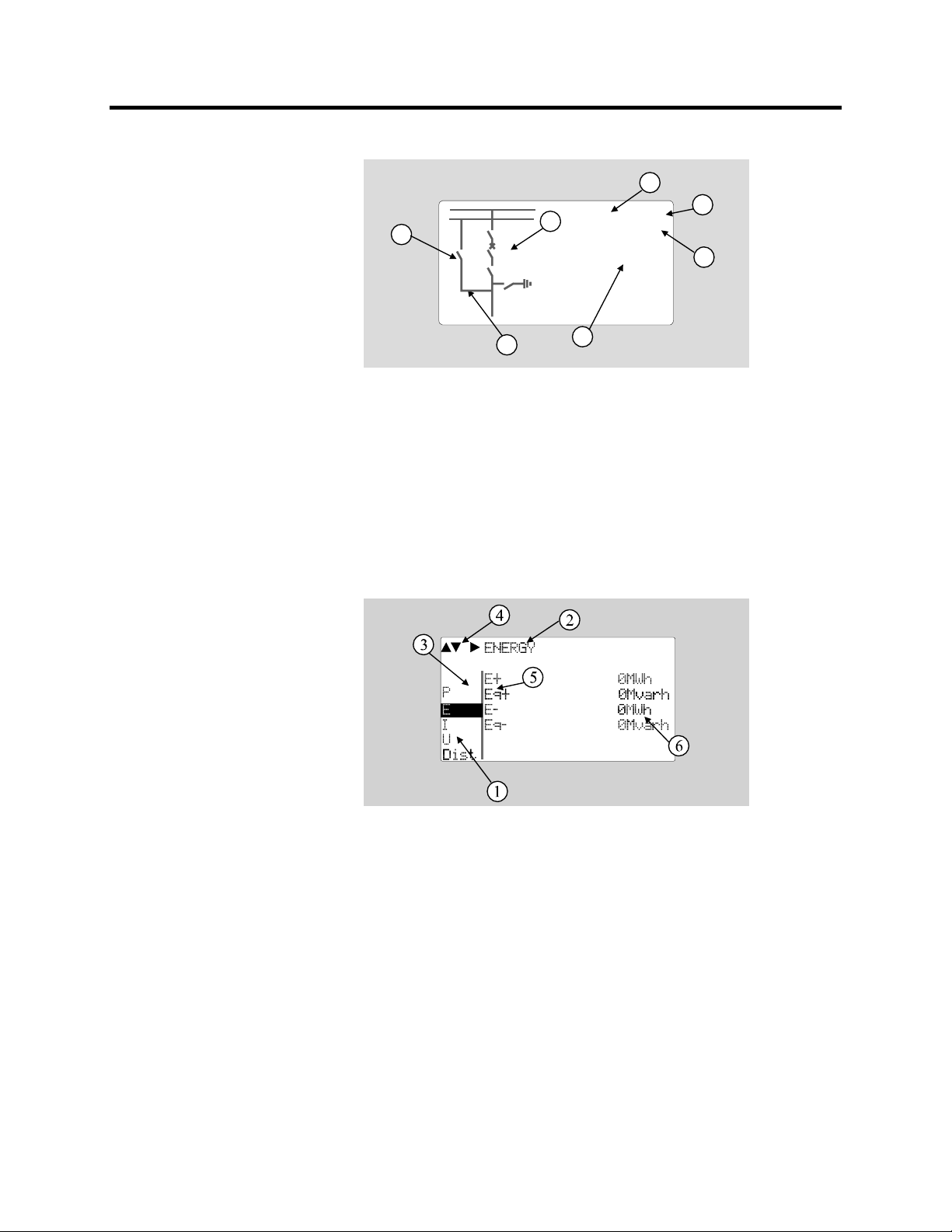
Figure 2.2 – Sections of the LCD Matrix Display
1. Freely configurable single-line diagram
2. Five controllable objects
3. Status for six independent objects
4. Bay identification
5. Local/Remote selection
6. Auto-reclose on/off selection (if applicable)
7. Freely selectable measurement values (max. six values)
Figure 2.3 – Sections of the LCD Matrix Display
1. Main menu column
2. The heading of the active menu
3. The cursor of the main menu
4. Possible navigating directions (push buttons)
5. Measured/setting parameter
6. Measured/set value
865-UM001A-EN-P – July 2009
Page 15
Local Panel User Interface 2-3
Backlight Control
Display backlight can be switched on with a digital input, virtual
input or virtual output. LOCALPANEL CONF/Display backlight
ctrl setting is used for selecting trigger input for backlight control.
When the selected input activates (rising edge), display backlight is
set on for 60 minutes.
Menu Navigation and Pointers
1. Use the arrow keys UP and DOWN to move up and down in the
main menu, that is, on the left-hand side of the display. The
active main menu option is indicated with a cursor. The options
in the main menu items are abbreviations, e.g. Evnt = events.
2. After any selection, the arrow symbols in the upper left corner of
the display show the possible navigating directions (applicable
navigation keys) in the menu.
3. The name of the active submenu and a possible ANSI code of
the selected function are shown in the upper part of the display,
e.g. CURRENTS.
4. Further, each display holds the measured values and units of one
or more quantities or parameters, e.g. ILmax 300A.
Keypad
You can navigate in the menu and set the required parameter
values using the keypad and the guidance given in the display.
Furthermore, the keypad is used to control objects and switches
on the single line diagram display. The keypad is composed of
four arrow keys, one cancel key, one enter key and one info key.
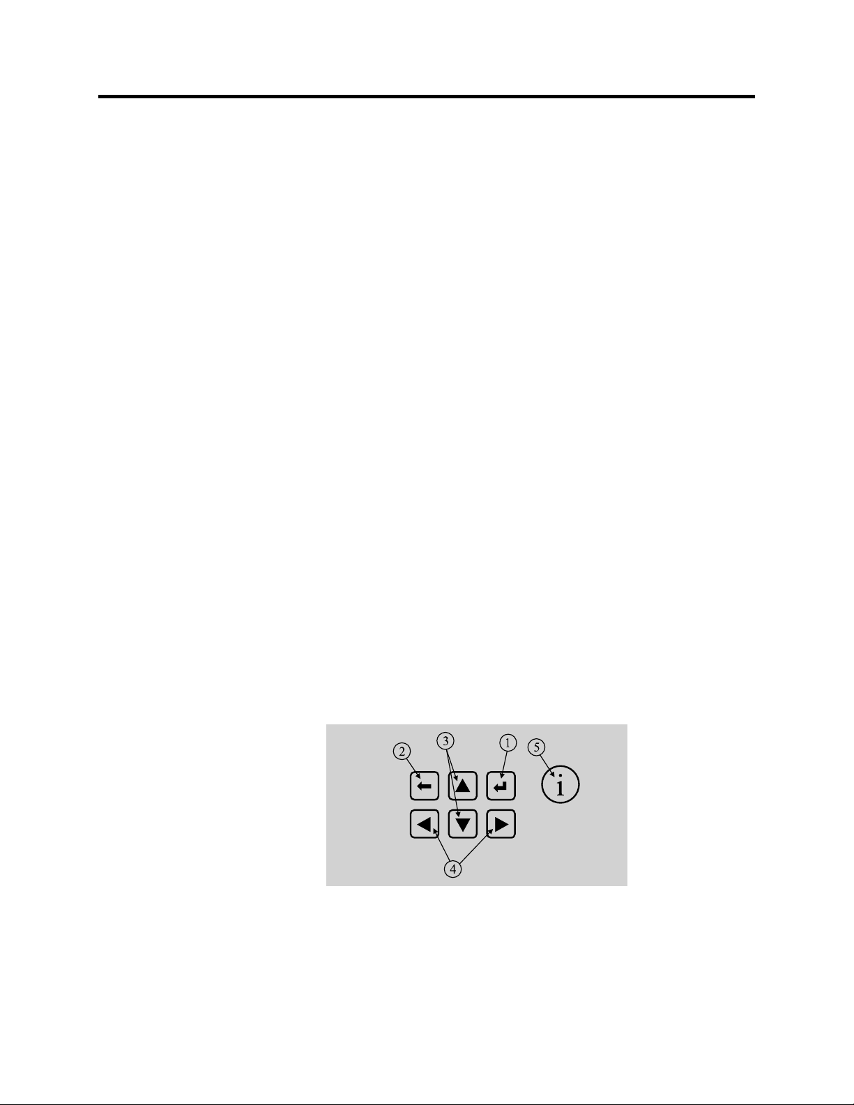
Figure 2-4 – Keys on the Keypad
1. Enter and confirmation key (ENTER)
2. Cancel key (CANCEL)
3. Up/Down [Increase/Decrease] arrow keys (UP/DOWN)
865-UM001A-EN-P – July 2009
Page 16

2-4 Local Panel User Interface
4. Keys for selecting submenus [selecting a digit in a numerical
value] (LEFT/RIGHT)
5. Additional information key (INFO)
NOTE: The term, which is used for the buttons in this manual,
is inside the rounded brackets.
Operation Indicators
The relay is provided with eight LED indicators:
Power
Error
Com
Alarm
Trip
A
B
C
Figure 2.5 – Operation Indicators of the Relay
Table 2.1 – Operation Indicators
LED indicator Meaning Measure/ Remarks
Power LED lit The power has been switched on Normal operation state
Error LED lit Internal fault, operates in parallel with
the self supervision output relay
Com LED lit or flashing The serial bus is in use and
transferring information
Alarm LED lit One or several signals of the output
relay matrix have been assigned to
output LA and the output has been
activated by one of the signals. (For
more information about output matrix,
please see page 2-24).
Trip LED lit One or several signals of the output
relay matrix have been assigned to
output Tr, and the output has been
activated by one of the signals. (For
more information about output relay
configuration, see “Configuring Digital
Outputs DO” on page 2-24).
A- C LED lit Application-related status indicators. Configurable
The relay attempts to reboot
[REBOOT]. If the error LED
remains lit, call for maintenance.
Normal operation state
The LED is switched off when the
signal that caused output Al to
activate, e.g. the START signal, is
reset. The resetting depends on the
type of configuration, connected or
latched.
The LED is switched off when the
signal that caused output Tr to
activate, e.g. the TRIP signal, is
reset. The resetting depends on the
type of configuration, connected or
latched.
865-UM001A-EN-P – July 2009
Page 17

Local Panel User Interface 2-5
Resetting Latched Indicators and Output Relays
All the indicators and output relays can be given a latching
function in the configuration.
There are several ways to reset latched indicators and relays:
• From the alarm list, move back to the initial display by pushing
the CANCEL key for approx. 3 s. Then reset the latched
indicators and output relays by pushing the ENTER key.
• Acknowledge each event in the alarm list one by one by pushing
the ENTER key equivalent times. Then, in the initial display,
reset the latched indicators and output relays by pushing the
ENTER key.
The latched indicators and relays can also be reset via a remote
communication bus or via a digital input configured for that
purpose.
Adjusting Display Contrast
The readability of the LCD varies with the brightness and the
temperature of the environment. The contrast of the display can
be adjusted via the PC user interface, and SetPointPS software.
Local Panel Operations The front panel can be used to control objects, change the local/
remote status, read the measured values, set parameters, and to
configure relay functions. Some parameters, however, can only be
set by means of a PC connected to one of the local communication
ports. Some parameters are factory-set.
Navigating in Menus
All the menu functions are based on the main menu/submenu structure:
1. Use the arrow keys UP and DOWN to move up and down in the
main menu.
2. To move to a submenu, repeatedly push the RIGHT key until the
required submenu is shown. Correspondingly, push the LEFT
key to return to the main menu.
3. Push the ENTER key to confirm the selected submenu. If there
are more than six items in the selected submenu, a black line
appears to the right side of the display (Figure 2.6). It is then
possible to scroll down in the submenu.
4. Push the CANCEL key to cancel a selection.
865-UM001A-EN-P – July 2009
Page 18
2-6 Local Panel User Interface
Local Panel Operations
(cont.)
5. Pushing the UP or DOWN key in any position of a sub-menu,
when it is not selected, brings you directly one step up or down
in the main menu.
The active main menu selection is indicated with black background
color. The possible navigating directions in the menu are shown in
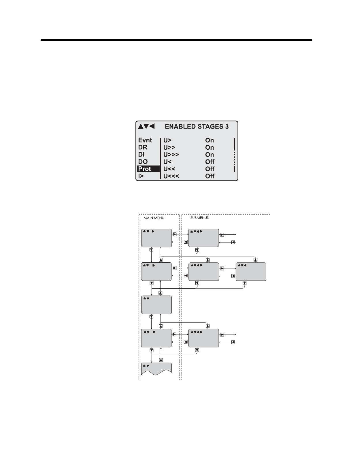
the upper-left corner by means of black triangular symbols.
Figure 2-6 – Example of Scroll Indication
Figure 2.7 – Principles of the Menu Structure and Navigation in the Menus
865-UM001A-EN-P – July 2009
Page 19

Local Panel User Interface 2-7
6. Push the INFO key to obtain additional information about any
menu item.
7. Push the CANCEL key to revert to the normal display.
Main Menu
The general menu structure is shown in Figure 2.7. The menu is
dependent on the user's configuration and the options according to
the order code. For example only the enabled protection stages will
appear in the menu.
Table 2.2 – List of the Local Main Menu
Main menu
1 Interactive mimic display 1
5 Double size measurements defined by the user 1
1 Title screen with device name, time and firmware version.
P 14 Power measurements
E 4 Energy measurements
I 13 Current measurements
U 15 Voltage measurements
Dema 15 Demand values
Umax 5 Time stamped min & max of voltages
Imax 9 Time stamped min & max of currents
Pmax 5 Time stamped min & max of power and frequency
Mont 21 Maximum values of the last 31 days and the last twelve months
Evnt 2 Events
DR 2 Disturbance recorder 2
Runh 2 Running hour counter. Active time of a selected digital input and
TIMR 6 Day and week timers
DI 5 Digital inputs including virtual inputs
DO 4 Digital outputs (relays) and output matrix
ExtAI 3 External analogue inputs 3
ExDI 3 External digital inputs 3
ExDO 3 External digital outputs 3
Prot 27 Protection counters, combined overcurrent status, protection
ΔI> 7 1st differential stages
ΔI>> 5 2nd differential stage
I> 5 1st overcurrent stage (primary side) 50/51 4
I>> 3 2nd overcurrent stage (primary side) 50/51 4
I’> 5 1st overcurrent stage (secondary side) 50/51 4
I’>> 3 2nd overcurrent stage (secondary side) 50/51 4
I2> 3 Current unbalance stage (primary side) 46 4
I’2> 3 Current unbalance stage (secondary side) 46 4
Number of
menus
Description ANSI code Note
time stamps of the latest start and stop.
status, protection enabling, cold load and inrush detectionIf2>
and block matrix
865-UM001A-EN-P – July 2009
Page 20

2-8 Local Panel User Interface
Local Panel Operations
(cont.)
Table 2.2 – List of the Local Main Menu (cont.)
Main menu
T> 3 Thermal overload stage 49 4
Io> 5 1st earth fault stage 50N/51N 4
Io>> 3 2nd earth fault stage 50N/51N 4
Io>>> 3 3rd earth fault stage 50N/51N 4
Io>>>> 3 4th earth fault stage 50N/51N 4
Prg1 3 1st programmable stage 4
Prg2 3 2nd programmable stage 4
Prg3 3 3rd programmable stage 4
Prg4 3 4th programmable stage 4
Prg5 3 5th programmable stage 4
Prg6 3 6th programmable stage 4
Prg7 3 7th programmable stage 4
Prg8 3 8th programmable stage 4
CBFP 3 Circuit breaker failure protection 50BF 4
CBWE 4 Circuit breaker wearing supervision 4
CTSV 1 CT supervisor 4
CT’SV 1 CT’ supervisor 4
ArcI> 4 Optional arc protection stage for phase-to-phase faults and
ArcIo> 3 Optional arc protection stage for earth faults. Current input = I01 50NARC 4
ArcIo2> 3 Optional arc protection stage for earth faults. Current input = I02 50NARC 4
OBJ 11 Object definitions 5
Lgic 2 Status and counters of user's logic 1
CONF 10+2 Device setup, scaling etc. 6
Bus 13 Serial port and protocol configuration 7
Diag 6 Device selfdiagnosis
Number of
menus
Description ANSI code Note
50ARC 4
delayed light signal.
NOTES:
1. Configuration is done with SetPointPS.
2. Recording files are read with SetPointPS.
3. The menu is visible only if protocol ”External IO” is selected for one of the serial ports.
Serial ports are configured in menu ”Bus”.
4. The menu is visible only if the stage is enabled.
5. Objects are circuit breakers, disconnectors, etc. Their position or status can be displayed
and controlled in the interactive mimic display.
6. There are two extra menus, which are visible only if the access level ”operator” or
”configurator” has been opened with the corresponding password.
7. Detailed protocol configuration is done with SetPointPS.
865-UM001A-EN-P – July 2009
Page 21

Local Panel User Interface 2-9
Menu Structure of Protection Functions
The general structure of all protection function menus is similar
although the details do differ from stage to stage. As an example the
details of the second overcurrent stage I>> menus are shown below:
F
IRST MENU OF I>> 50/51 STAGE
I>> STATUS 50/51
Off
5
2
1
-
ExDO
Prot
I>
I>>
Iv>
Figure 2.8 – First Menu of I>>50/51 Stage
I>j
Status
SCntr
TCntr
SetGrp
SGrpDI
Force
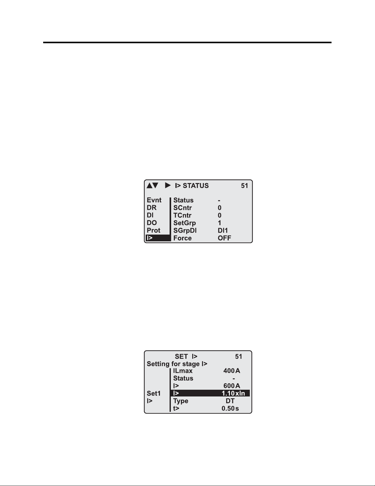
This is the status, start and trip counter and setting group menu. The
content is:
• Status – The stage is not detecting any fault at the moment. The
stage can also be forced to pick-up or trip if the operating level is
"Configurator" and the force flag below is on. Operating levels
are explained in section “Operating Levels”.
• SCntr 5 – The stage has picked-up a fault five times since the
last reset of restart. This value can be cleared if the operating
level is at least "Operator".
• TCntr 1 – The stage has tripped two times since the last reset of
restart. This value can be cleared if the operating level is at least
"Operator".
• SetGrp 1 – The active setting group is one. This value can be
edited if the operating level is at least “Operator”. Setting groups
are explained in section “Setting Groups”.
• SGrpDI – The setting group is not controlled by any digital
input. This value can be edited if the operating level is at least
“Configurator”.
• Force Off – The status forcing and output relay forcing is
disabled. This force flag status can be set to “On” or back to
“Off” if the operating level is at least “Configurator”. If no front
panel button is pressed within five minutes and there is no
SetPointPS communication, the force flag will be set to “Off”
position. The forcing is explained in section “Forced Control
(Force)”.
865-UM001A-EN-P – July 2009
Page 22

2-10 Local Panel User Interface
Local Panel Operations
(cont.)
S
Figure 2.9 – Second Menu (next to the right) of I>>50/51 Stage
This is the main setting menu. The content is:
• Stage setting group 1 – These are the group 1 setting values.
ECOND MENU OF I>> 50/51 STAGE
I>> SET 50/51
Stage setting group 1
ExDI
ExDO
Prot
I>>
CBWE
OBJ
ILmax
Status
I>>
I>>
t>>
403A
-
1013A
2.50xIgn
0.60s
The other setting group can be seen by pressing push buttons
ENTER and then RIGHT or LEFT. Setting groups are explained
in section “Setting Groups”.
• Ilmax 403A – The maximum of the three measured phase
currents is at the moment 403 A. This is the value the stage is
supervising.
• Status – Status of the stage. This is just a copy of the status
value in the first menu.
• I>> 1013 A – The pick-up limit is 1013 A in primary value.
• I>> 2.50xIn – The pick-up limit is 2.50 times the rated current
of the protected object. This value can be edited if the operating
level is at least "Operator". Operating levels are explained in
section “Operating Levels”.
• t>> 0.60s – The total operation delay is set to 600 ms. This value
can be edited if the operating level is at least "Operator".
865-UM001A-EN-P – July 2009
Page 23

Local Panel User Interface 2-11
T
HIRD MENU OF I>> 50/51 STAGE
I>> LOG 50/51
FAULT LOG 1
ExDI
ExDO
Prot
I>>
CBWE
OBJ
Figure 2.10 – Third and Last Menu (next to the right) of I>>50/51 Stage
2006-09-14
12:25:10.288
Type
Flt
Load
EDly
1-2
2.86xIgn
0.99xIgn
81%
SetGrp 1
This is the menu for registered values by the I>> stage. Fault logs are
explained under “Fault Logs” on page 2-13.
• FAULT LOG 1 – This is the latest of the eight available logs.
You may move between the logs by pressing push buttons
ENTER and then RIGHT or LEFT.
• 2006-09-14 – Date of the log.
• 12:25:10.288 – Time of the log
• Type 1-2 – The overcurrent fault has been detected in phases L1
and L2 (A & B, red & yellow, R&S, u&v).
• Flt 2.86xIn – The fault current has been 2.86 per unit.
• Load 0.99xIn – The average load current before the fault has
been 0.99 pu.
• EDly 81% – The elapsed operation delay has been 81% of the
setting 0.60 s = 0.49 s. Any registered elapsed delay less than
100 % means that the stage has not tripped, because the fault
duration has been shorter than the delay setting.
• SetGrp 1 – The setting group has been 1. This line can be
reached by pressing ENTER and several times the DOWN
button.
865-UM001A-EN-P – July 2009
Page 24
2-12 Local Panel User Interface
Local Panel Operations
(cont.)
Setting Groups
Most of the protection functions of the relay have two setting groups.
These groups are useful for example when the network topology is
changed frequently. The active group can be changed by a digital input,
through remote communication or locally by using the local panel.
The active setting group of each protection function can be selected
separately. Figure 2.11 shows an example where the changing of the
I> setting group is handled with digital input one (SGrpDI). If the
digital input is TRUE, the active setting group is group two and
correspondingly, the active group is group one, if the digital input is
FALSE. If no digital input is selected (SGrpDI = -), the active group
can be selected by changing the value of the parameter SetGrp.
Figure 2.11 – Example of Protection Submenu with Setting Group
The changing of the setting parameters can be done easily. When the
desired submenu has been found (with the arrow keys), press the
ENTER key to select the submenu. Now the selected setting group is
indicated in the down-left corner of the display (See Figure 2.12).
Set1 is setting group one and Set2 is setting group two. When the
needed changes, to the selected setting group, have been done, press
the LEFT or the RIGHT key to select another group (the LEFT key
is used when the active setting group is 2 and the RIGHT key is used
when the active setting group is 1).
Figure 2.12 – Example of I> Setting Submenu
865-UM001A-EN-P – July 2009
Page 25
Local Panel User Interface 2-13
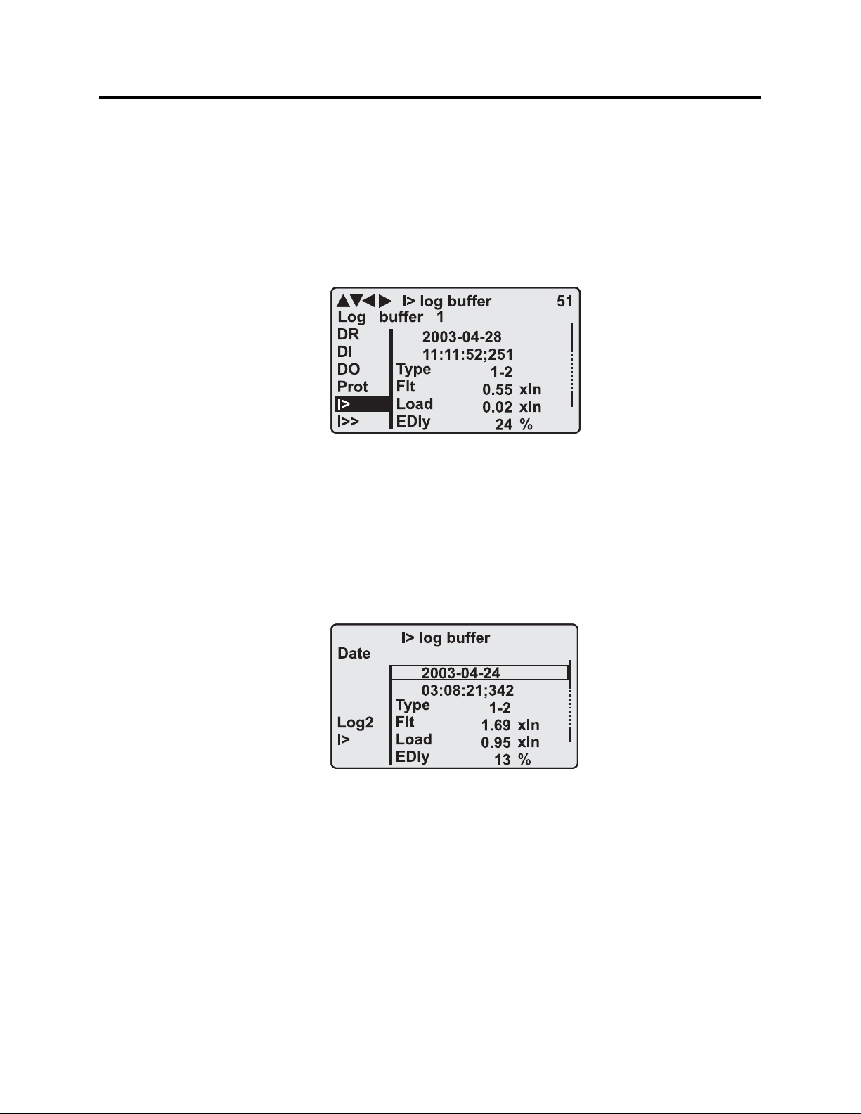
Fault Logs
All the protection functions include fault logs. The fault log of a
function can register up to eight different faults with time stamp
information, fault values etc. Each function has its own logs (See
Figure 2.13).
Figure 2.13 – Example of Fault Log
To see the values of, for example, log two, press the ENTER key to
select the current log (log one). The current log number is then
indicated in the down-left corner of the display (See Figure 2.14,
Log2 = log two). The log two is selected by pressing the RIGHT key
once.
Figure 2.14 – Example of Selected Fault Log
865-UM001A-EN-P – July 2009
Page 26

2-14 Local Panel User Interface
Operating Levels
Local Panel Operations
(cont.)
The relay has three operating levels: User level, Operator level
and Configurator level. The purpose of the access levels is to
prevent accidental change of relay configurations, parameters or
settings.
USER level
Use: Possible to read e.g. parameter values,
measurements and events
Opening: Level permanently open
Closing: Closing not possible
OPERATOR level
Use: Possible to control objects and to change e.g. the
settings of the protection stages
Opening: Default password is 1
Setting State: Push ENTER
Closing: The level is automatically closed after 10 minutes
idle time. Giving the password 9999 can also close
the level.
CONFIGURATION level
Use: The configurator level is needed during the
commissioning of the relay. E.g. the scaling of the
voltage and current transformers can be set.
Opening: Default password is 0002
Setting State: Push ENTER
Closing: The level is automatically closed after 10 minutes
idle time. Giving the password 9999 can also close
the level.
865-UM001A-EN-P – July 2009
Page 27

Local Panel User Interface 2-15
Opening Access
1. Push the INFO key and the ENTER key on the front panel.
ENTER PASSWORD
0
***
Figure 2.15 – Opening the Access Level
2. Enter the password needed for the desired level: the password
can contain four digits. The digits are supplied one by one by
first moving to the position of the digit using the RIGHT key and
then setting the desired digit value using the UP key.
3. Push the ENTER key.
Password Handling
The passwords can only be changed using SetPointPS software
connected to the local RS-232 port on the relay.
It is possible to restore the password(s) in case the password is lost or
forgotten. In order to restore the password(s), a relay program is
needed. The serial port settings are 38400 bps, 8 data bits, no parity
and one stop bit. The bit rate is configurable via the front panel.
Command Description
get pwd_break Get the break code (Example: 6569403)
get serno Get the serial number of the relay (Example: 12345)
Send both the numbers to Rockwell Automation and ask for a
password break. A device specific break code is sent back to you.
That code will be valid for the next two weeks only for this specific
device.
Command Description
set pwd_break=4435876 Restore the factory default passwords (“4435876” is
just an example. The actual code should be
requested from Rockwell Automation.)
Now the passwords are restored to the default values (See section
“Operating Levels”).
865-UM001A-EN-P – July 2009
Page 28

2-16 Local Panel User Interface
Operating Measures Control Functions
The default display of the local panel is a single-line diagram
including relay identification, Local/Remote indication, Auto-reclose
on/off selection and selected analogue measurement values.
Please note that the operator password must be active in order to be
able to control the objects. Please refer to ‘Opening Access’ on
page 2-15.
Toggling Local/Remote Control
1. Push the ENTER key. The previously activated object starts to
blink.
2. Select the Local/Remote object (“L” or “R” squared) by using
the arrow keys.
3. Push the ENTER key. The L/R dialog opens. Select “REMOTE”
to enable remote control and disable local control. Select
“LOCAL” to enable local control and disable remote control.
4. Confirm the setting by pushing the ENTER key. The
Local/Remote state will change.
Object Control
1. Push the ENTER key. The previously activated object starts to
blink.
2. Select the object to control by using the arrow keys. Please note
that only controllable objects can be selected.
3. Push the ENTER key. A control dialog opens.
4. Select the “Open” or “Close” command by using the UP and
DOWN arrow keys.
5. Confirm the operation by pushing the ENTER key. The state of
the object changes.
Toggling Virtual Inputs
1. Push the ENTER key. The previously activated object starts to
blink.
2. Select the virtual input object (empty or black square)
3. The dialog opens
4. Select “VIon” to activate the virtual input or select “VIoff” to
deactivate the virtual input
865-UM001A-EN-P – July 2009
Page 29

Local Panel User Interface 2-17
Measured Data
The measured values can be read from the main menus and their
submenus. Furthermore, any measurement value in the following
table can be displayed on the main view next to the single line
diagram. Up to six measurements can be shown.
Table 2.3 – Measured Values
Value Menu/Submenu Description
f P/POWER Frequency [Hz]
IL1 I/PHASE CURRENTS Phase current IL1 [A]
IL2 I/PHASE CURRENTS Phase current IL2 [A]
IL3 I/PHASE CURRENTS Phase current IL3 [A]
IL1da I/PHASE CURRENTS 15 min average for IL1 [A]
IL2da I/PHASE CURRENTS 15 min average for IL2 [A]
IL3da I/PHASE CURRENTS 15 min average for IL3 [A]
I’L1 I/PHASE CURRENTS Phase current I’L1 [A]
I’L2 I/PHASE CURRENTS Phase current I’L2 [A]
I’L3 I/PHASE CURRENTS Phase current I’L3 [A]
I’L1da I/PHASE CURRENTS 15 min average for I’L1 [A]
I’L2da I/PHASE CURRENTS 15 min average for I’L2 [A]
I’L3da I/PHASE CURRENTS 15 min average for I’L3 [A]
Io I/SYMMETRIC CURRENTS Primary value of zero sequence/ residual current Io [A]
Io2 I/SYMMETRIC CURRENTS Primary value of zero-sequence/residual current Io2 [A]
IoC I/SYMMETRIC CURRENTS Calculated Io [A]
I1 I/SYMMETRIC CURRENTS Positive sequence current [A]
I2 I/SYMMETRIC CURRENTS Negative sequence current [A]
I2/I1 I/SYMMETRIC CURRENTS Negative sequence current related to positive sequence current
(for unbalance protection) [%]
I’1 I/SYMMETRIC CURRENTS Positive sequence current [A]
I’2 I/SYMMETRIC CURRENTS Negative sequence current [A]
I’2/I’1 I/SYMMETRIC CURRENTS Negative sequence current related to positive sequence current
(for unbalance protection) [%]
THDIL I/HARM. DISTORTION Total harmonic distortion of the mean value of phase currents [%]
THDIL1 I/HARM. DISTORTION Total harmonic distortion of phase current IL1 [%]
THDIL2 I/HARM. DISTORTION Total harmonic distortion of phase current IL2 [%]
THDIL3 I/HARM. DISTORTION Total harmonic distortion of phase current IL3 [%]
THDI’L1 I/HARM. DISTORTION Total harmonic distortion of phase current I’L1 [%]
THDI’L2 I/HARM. DISTORTION Total harmonic distortion of phase current I’L2 [%]
THDI’L3 I/HARM. DISTORTION Total harmonic distortion of phase current I’L3 [%]
Diagram I/HARMONICS of IL1 Harmonics of phase current IL1 [%] (See Figure 2.16)
Diagram I/HARMONICS of IL2 Harmonics of phase current IL2 [%] (See Figure 2.16)
Diagram I/HARMONICS of IL3 Harmonics of phase current IL3 [%] (See Figure 2.16)
Diagram I/HARMONICS of I’L1 Harmonics of phase current I’L1 [%] (See Figure 2.16)
Diagram I/HARMONICS of I’L2 Harmonics of phase current I’L2 [%] (See Figure 2.16)
Diagram I/HARMONICS of I’L3 Harmonics of phase current I’L3 [%] (See Figure 2.16)
865-UM001A-EN-P – July 2009
Page 30
2-18 Local Panel User Interface
Operating measures (cont.)
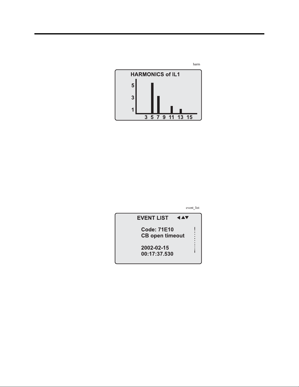
Figure 2.16 – Example of Harmonics Bar Display
Reading Event Register
The event register can be read from the EVNT submenu:
1. Push the RIGHT key once.
2. The EVENT LIST appears. The display contains a list of all the
events that have been configured to be included in the event
register.
Figure 2.17 – Example of an Event Register
3. Scroll through the event list with the UP and DOWN keys.
4. Exit the event list by pushing the LEFT key.
It is possible to set the order in which the events are sorted. If the
“Order” -parameter is set to “New-Old”, then the first event in
the EVENT LIST is the most recent event.
865-UM001A-EN-P – July 2009
Page 31

Local Panel User Interface 2-19
Forced Control (Force)
In some menus it is possible to switch a signal on and off by using
a force function. This feature can be used, for instance, for testing
a certain function. The force function can be activated as follows:
1. Move to the setting state of the desired function, for example DO
(see section “Configuration and Parameter Setting”).
2. Select the Force function (the background color of the force text
is black).
Figure 2.18 – Selecting Force Function
3. Push the ENTER key.
4. Push the UP or DOWN key to change the "OFF" text to "ON",
that is, to activate the Force function.
5. Push the ENTER key to return to the selection list. Choose the
signal to be controlled by force with the UP and DOWN keys,
for instance the T1 signal.
6. Push the ENTER key to confirm the selection. Signal T1 can
now be controlled by force.
7. Push the UP or DOWN key to change the selection from "0" (not
alert) to "1" (alert) or vice versa.
8. Push the ENTER key to execute the forced control operation of
the selected function, e.g., making the output relay of T1 to pick up.
9. Repeat the steps 7 and 8 to alternate between the on and off state
of the function.
10. Repeat the steps 1...4 to exit the Force function.
11. Push the CANCEL key to return to the main menu.
NOTE: All the interlockings and blockings are bypassed when
the force control is used.
865-UM001A-EN-P – July 2009
Page 32

2-20 Local Panel User Interface
Configuration and
The minimum procedure to configure a relay is:
Parameter Setting
1. Open the access level "Configurator". The default password for
configurator access level is 2.
2. Set the rated values in menu [CONF] including at least current
transformers and a protected transformer rating. Also the date
and time settings are in this same main menu.
3. Enable the needed protection functions and disable the rest of the
protection functions in main menu [Prot].
4. Set the setting parameter of the enable protection stages
according the application.
5. Connect the output relays to the start and trip signals of the
enabled protection stages using the output matrix. This can be
done in main menu [DO], although the SetPointPS program is
recommended for output matrix editing.
6. Configure the needed digital inputs in main menu [DI].
7. Configure blocking and interlockings for protection stages using
the block matrix. This can be done in main menu [Prot], although
SetPointPS is recommended for block matrix editing.
Some of the parameters can only be changed via the RS-232
serial port using the SetPointPS software. Such parameters, (for
example passwords, blockings and mimic configuration) are
normally set only during commissioning.
Some of the parameters require the restarting of the relay. This
restarting is done automatically when necessary. If a parameter
change requires restarting, the display will show as Figure 2.19.
Figure 2.19 – Example of Auto-Reset Display
Press CANCEL to return to the setting view. If a parameter must
be changed, press the ENTER key again. The parameter can now
be set. When the parameter change is confirmed with the
ENTER key, a [RESTART]- text appears to the top-right corner
of the display. This means that auto-resetting is pending. If no
key is pressed, the auto-reset will be executed within few seconds.
865-UM001A-EN-P – July 2009
Page 33

Local Panel User Interface 2-21
Parameter Setting
1. Move to the setting state of the desired menu (for example
CONF/CURRENT SCALING) by pushing the ENTER key. The
Pick text appears in the upper-left part of the display.
2. Enter the password associated with the configuration level by
pushing the INFO key and then using the arrow keys and the
ENTER key (default value is 0002). For more information about
the access levels, please refer to section “Operating Levels”.
3. Scroll through the parameters using the UP and DOWN keys. A
parameter can be set if the background color of the line is black.
If the parameter cannot be set the parameter is framed.
4. Select the desired parameter (for example Inom) with the
ENTER key.
5. Use the UP and DOWN keys to change a parameter value. If the
value contains more than one digit, use the LEFT and RIGHT
keys to shift from digit to digit, and the UP and DOWN keys to
change the digits.
6. Push the ENTER key to accept a new value. If you want to leave
the parameter value unchanged, exit the edit state by pushing the
CANCEL key.
Figure 2.20 – Changing Parameters
865-UM001A-EN-P – July 2009
Page 34

2-22 Local Panel User Interface
Configuration and
Setting Range Limits
Parameter Setting
If the given parameter setting values are out-of-range values, a
(cont.)
fault message will be shown when the setting is confirmed with
the ENTER key. Adjust the setting to be within the allowed range.
Figure 2.21 – Example of a Fault Message
The allowed setting range is shown in the display in the setting
mode. To view the range, push the INFO key. Push the
CANCEL key to return to the setting mode.
Figure 2.22 – Allowed Setting Ranges shown in the Display
865-UM001A-EN-P – July 2009
Page 35

Local Panel User Interface 2-23
Disturbance Recorder Menu DR
Via the submenus of the disturbance recorder menu the
following functions and features can be read and set:
DISTURBANCE RECORDER
• Recording mode (Mode)
• Sample rate (Rate)
• Recording time (Time)
• Pre trig time (PreTrig)
• Manual trigger (MnlTrig)
• Count of ready records (ReadyRe)
REC. COUPLING
• Add a link to the recorder (AddLink)
• Clear all links (ClrLnks)
Available links:
• DO, DI
• IL, I’L
• I2/In, I2/I1, I2, I1, IoCalc, I2/In, I’2/I’1, I’2, I’1, I’oCalc
• f
• Io2, Io1
• IL3, IL2, IL1, I’L3, I’L2, I’L1
• IL1RMS, IL2RMS, IL3RMS
• ILmin, ILmax, I’Lmin, I’Lmax
• ΔIl1, ΔIl2, ΔIl3
• IL1w, IL2w, IL3w, I’L1w, I’L2w, I’L3w
Configuring Digital Inputs DI
The following functions can be read and set via the submenus of
the digital inputs menu:
• The status of digital inputs (DIGITAL INPUTS 1-6)
• Operation counters (DI COUNTERS)
• Operation delay (DELAYs for DigIn)
• The polarity of the input signal (INPUT POLARITY). Either
normally open (NO) or normally closed (NC) circuit.
• Event enabling EVENT MASK1
865-UM001A-EN-P – July 2009
Page 36

(
2-24 Local Panel User Interface
Configuration and
Configuring Digital Outputs DO
Parameter Setting
The following functions can be read and set via the submenus of
cont.)
the digital outputs menu:
• The status of the output relays (RELAY OUTPUTS1 and 2)
• The forcing of the output relays (RELAY OUTPUTS1 and 2)
(only if Force = ON):
– Forced control (0 or 1) of the Trip relays
– Forced control (0 or 1) of the Alarm relays
– Forced control (0 or 1) of the IF relay
• The configuration of the output signals to the output relays. The
configuration of the operation indicators (LED) Alarm and Trip
and application specific alarm leds A, B and C (that is, the output
relay matrix).
NOTE: The amount of Trip and Alarm relays depends on the relay
type and optional hardware.
Protection Menu Prot
The following functions can be read and set via the submenus of
the Prot menu:
Reset all the counters (PROTECTION SET/ClAll)
Read the status of all the protection functions (PROTECT
STATUS 1-x)
Enable and disable protection functions (ENABLED STAGES
1-x)
Define the interlockings between signals (only with SetPointPS).
Each stage of the protection functions can be disabled or enabled
individually in the Prot menu. When a stage is enabled, it will be
in operation immediately without a need to reset the relay.
The relay includes several protection functions. However, the
processor capacity limits the number of protection functions that
can be active at the same time.
865-UM001A-EN-P – July 2009
Page 37

Local Panel User Interface 2-25
Configuration Menu CONF
The following functions and features can be read and set via the
submenus of the configuration menu:
DEVICE SETUP
• Bit rate for the command line interface in ports X4 and the front
panel. The front panel is always using this setting. If SPABUS
is selected for the rear panel local port X4, the bit rate is
according SPABUS settings.
• Access level [Acc]
LANGUAGE
• List of available languages in the relay
CURRENT SCALING
• Rated phase CT primary current (Inom)
• Rated phase CT secondary current (Isec)
• Rated input of the relay [Iinput]. 5 A or 1 A. This is specified in
the order code of the device.
• Rated phase CT’ primary current (I’nom)
• Rated phase CT’ secondary current (I’sec)
• Rated input of the relay [I’input]. 5 A or 1 A. This is specified in
the order code of the device.
• Rated value of I
• Rated value of I
CT primary current (Ionom)
0
CT secondary current (Iosec)
0
• Rated I01 input of the relay [Ioinp]. 5 A or 1 A. This is specified
in the order code of the device.
• Rated value of I
• Rated value of I
CT primary current (Io2nom)
02
CT secondary current (Io2sec)
02
• Rated I02 input of the relay [Io2inp]. 5A, 1 A or 0.2 A. This is
specified in the order code of the device.
The rated input values are usually equal to the rated secondary
value of the CT.
The rated CT secondary may be greater than the rated input but
the continuous current must be less than four times the rated
input. In compensated, high impedance earthed and isolated
networks using cable transformer to measure residual current I
,
0
it is quite usual to use a relay with 1 A or 0.2 A input although
the CT is 5 A or 1A. This increases the measurement accuracy.
The rated CT secondary may also be less than the rated input but
the measurement accuracy near zero current will decrease.
865-UM001A-EN-P – July 2009
Page 38

(
2-26 Local Panel User Interface
Configuration and
TRANSFORMER SETTING
Parameter Setting
cont.)
• Rated voltage in IL side (typically high voltage side)
• Rated voltage in I’L side (typically low voltage side)
• Rated power of transformer
• Connection group of transformer
• Zero current compensation in IL side (If transformer is earthed in
IL side, this must set as “ON”)
• Zero current compensation in I’L side (If transformer is earthed
in I’L side, this must set as “ON”)
• Connection group of the unit transformer, if any. IEC marking
with capital letters Y and D for HV side and small case letters y
and d for LV side combined with the dial hour is used. For
example Yd11 means a wye-delta transformer where the delta
side phase-to-ground voltages are leading 30° the wye side
phase-to-ground voltages.
DEVICE INFO
• Relay type (Type ALLEN BRADLEY 865)
• Serial number (SerN)
• Software version (PrgVer)
• Bootcode version (BootVer)
DATE/TIME SETUP
• Day, month and year (Date)
• Time of day (Time)
• Date format (Style). The choices are "yyyy-mm-dd",
"dd.nn.yyyy" and "mm/dd/yyyy".
CLOCK SYNCHRONISATION
• Digital input for minute sync pulse (SyncDI). If any digital input
is not used for synchronization, select "".
• Daylight saving time for NTP synchronization (DST).
• Detected source of synchronization (SyScr).
• Synchronization message counter (MsgCnt).
• Latest synchronization deviation (Dev).
The following parameters are visible only when the access level is
higher than "User".
• Offset, i.e. constant error, of the synchronization source (SyOS).
• Auto adjust interval (AAIntv).
• Average drift direction (AvDrft): "Lead" or "lag".
• Average synchronization deviation (FilDev).
865-UM001A-EN-P – July 2009
Page 39

Local Panel User Interface 2-27
Protocol Menu Bus
There are three communication ports in the rear panel. In
addition there is a connector in the front panel overruling the
local port in the rear panel.
REMOTE PORT X5
• Communication protocol for remote port X5 [Protocol].
• Message counter [Msg#]. This can be used to verify that the
device is receiving messages.
• Communication error counter [Errors].
• Communication time-out error counter [Tout].
• Information of bit rate/data bits/parity/stop bits.
This value is not directly editable. Editing is done in the
appropriate protocol setting menus.
The counters are useful when testing the communication.
LOCAL PORT X4 (pins 2, 3 and 5)
This port is disabled, if a cable is connected to the front panel
connector.
• Communication protocol for the local port X4 [Protocol]. For
SetPointPS use "None" or "SPABUS".
• Message counter [Msg#]. This can be used to verify that the
device is receiving messages.
• Communication error counter [Errors].
• Communication time-out error counter [Tout].
• Information of bit rate/data bits/parity/stop bits.
This value is not directly editable. Editing is done in the
appropriate protocol setting menus. For SetPointPS and protocol
"None" the setting is done in menu CONF/DEVICE SETUP.
PC (LOCAL/SPA BUS)
This is a second menu for local port X4. The SetPointPS
communication status is showed.
• Bytes/size of the transmitter buffer [Tx].
• Message counter [Msg#]. This can be used to verify that the
device is receiving messages.
• Communication error counter [Errors]
• Communication time-out error counter [Tout].
• Same information as in the previous menu.
865-UM001A-EN-P – July 2009
Page 40

2-28 Local Panel User Interface
Configuration and
EXTENSION PORT X4 (pins 7, 8 and 5)
Parameter Setting
(cont.)
• Communication protocol for extension port X4 [Protocol].
• Message counter [Msg#]. This can be used to verify that the
device is receiving messages.
• Communication error counter [Errors].
• Communication time-out error counter [Tout].
• Information of bit rate/data bits/parity/stop bits.
This value is not directly editable. Editing is done in the
appropriate protocol setting menus.
MODBUS
• Modbus address for this slave device [Addr]. This address has to
be unique within the system.
• Modbus bit rate [bit/s]. Default is "9600".
• Parity [Parity]. Default is "Even".
For details see the technical description part of the manual.
EXTERNAL I/O protocol
This is a Modbus master protocol to communicate with the
extension I/O modules connected to the extension port. Only one
instance of this protocol is possible.
• Bit rate [bit/s]. Default is "9600".
• Parity [Parity]. Default is "Even".
For details see the technical description part of the manual.
SPA BUS
Several instances of this protocol are possible.
• SPABUS address for this device [Addr]. This address has to be
unique within the system.
• Bit rate [bit/s]. Default is "9600".
• Event numbering style [Emode]. Default is "Channel".
For details see the technical description part of the manual.
IEC 60870-5-103
Only one instance of this protocol is possible.
• Address for this device [Addr]. This address has to be unique
within the system.
• Bit rate [bit/s]. Default is "9600".
• Minimum measurement response interval [MeasInt].
• ASDU6 response time mode [SyncRe].
For details see the technical description part of the manual.
IEC 103 DISTURBANCE RECORDINGS
For details see the technical description part of the manual.
865-UM001A-EN-P – July 2009
Page 41

Local Panel User Interface 2-29
PROFIBUS
Only one instance of this protocol is possible.
• [Mode]
• Bit rate [bit/s]. Use 2400 bps. This parameter is the bit rate
between the main CPU and the Profibus ASIC. The actual
Profibus bit rate is automatically set by the Profibus master and
can be up to 12 Mbit/s.
• Event numbering style [Emode].
• Size of the Profibus Tx buffer [InBuf].
• Size of the Profibus Rx buffer [OutBuf].
When configuring the Profibus master system, the length of
these buffers are needed. The size of the both buffers is set
indirectly when configuring the data items for Profibus.
• Address for this slave device [Addr]. This address has to be
unique within the system.
• Profibus converter type [Conv]. If the shown type is a dash “-“,
either Profibus protocol has not been selected or the device has
not restarted after protocol change or there is a communication
problem between the main CPU and the Profibus ASIC.
For details see the technical description part of the manual.
DNP3
Only one instance of this protocol is possible.
• Bit rate [bit/s]. Default is "9600".
• [Parity].
• Addres for this device [SlvAddr]. This address has to be unique
within the system.
• Master's addres [MstrAddr].
For further details see the technical description part of the manual.
TCP/IP
These TCP/IP parameters are used by the ethernet interface module.
For changing the nnn.nnn.nnn.nnn style parameter values,
SetPointPS is recommended.
• IP address [IpAddr].
• Net mask [NetMsk].
• Gateway [Gatew].
• Name server [NameSw].
• Network time protocol (NTP) server [NTPSvr].
• Protocol port for IP [Port]. Default is 502.
865-UM001A-EN-P – July 2009
Page 42

2-30 Local Panel User Interface
Configuration and
Parameter Setting
The optional plug on DeviceNet Communication Module provides
(cont.)
DEVICENET
the following features:
Node address and network data rate is programmable through the
front panel of the 865 relay.
Alternatively, the configuration settings can be accomplished
over the DeviceNet network, utilizing a network configuration
tool such as RSNetWorx for DeviceNet.
The status of the module is reported the status of the device bus
and network communications.
UCMM (Unconnected Message Manager) messages are
supported with the ability to allocate up to 3 explicit message
connections concurrently.
DeviceNet Group 2 slave functionality including:
– Explicit connection
– Polled connection
– 1 COS (Change of State)/Cyclic connection
Full DeviceNet Parameter Object support allows EDS files to be
extracted from all units.
TCP/IP [Ethernet]
These TCP/IP parameters are used by the ethernet interface module.
For changing the nnn.nnn.nnn.nnn style parameter values,
SetPointPS is recommended.
IP address [IpAddr].
Net mask [NetMsk].
Gateway [Gatew].
Name server [NameSw].
Network time protocol (NTP) server [NTPSvr].
Protocol port for IP [Port]. Default is 502.
Single Line Diagram Editing
The single-line diagram is drawn with the SetPointPS software. For
more information, please refer to the SetPointPS manual.
865-UM001A-EN-P – July 2009
Page 43

Local Panel User Interface 2-31
Bay
0 L
0A
0.000A
0kW
0Kvar
Figure 2.23 – Single Line Diagram
Blocking and Interlocking Configuration
The configuration of the blockings and interlockings is done with the
SetPointPS software. Any start or trip signal can be used for
blocking the operation of any protection stage. Furthermore, the
interlocking between objects can be configured in the same blocking
matrix of the SetPointPS software. For more information, please
refer to the SetPointPS manual.
SetPointPS PC Software The PC user interface can be used for:
On-site parameter setting of the relay
Loading relay software from a computer
Reading measured values, registered values and events to a
computer
Continuous monitoring of all values and events
Two RS-232 serial ports are available for connecting a local PC with
SetPointPS to the relay; one on the front panel and one on the rear
panel of the relay. These two serial ports are connected in parallel.
However, if the connection cables are connected to both ports, only
the port on the front panel will be active. To connect a PC to a serial
port, use connection cable part no. 857-VX003-3.
The SetPointPS program can also use TCP/IP LAN connection.
Optional hardware is required.
There is a free of charge PC program called SetPointPS available for
configuration and setting of Allen-Bradley relays. Please download
the latest SetPointPS.exe from our web page www.AB.com
. For
more information about the SetPointPS software, please refer to the
user’s manual, Publication 857-PM001A-EN-P. Also the SetPointPS
user’s manual is available at our web site.
865-UM001A-EN-P – July 2009
Page 44

2-32 Local Panel User Interface
865-UM001A-EN-P – July 2009
Page 45

Chapter 3
Protection Functions
Each protection stage can independently be enabled or disabled
according to the requirements of the intended application.
The device limits the maximum number of enabled stages to about
Maximum Number of
Protection Stages
in one application
Table 3.1 – List of Protection Functions
Protection Functions
30, depending on the type of the stages. For more information,
please see the configuration instructions in Chapter 2 in the first part
of this manual.
IEEE/
ANSI code
50/51 3I>, 3I>>, 3I’>, 3I’>> Overcurrent protection
87 ∆I>, ∆I>> Differential overcurrent protection
46 I2>, I’2> Current unbalance protection
49 T> Thermal overload protection
50N/51N
50BF CBFP Circuit-breaker failure protection
99 Prg1...8 Programmable stages
50ARC
50NARC
IEC Symbol Function Name
>,
I
0
>>,
I
0
I
>>>,
0
>>>>
I
0
ArcI>, ArcI’>
>, ArcI02>
ArcI
01
Earth fault protection
Optional arc fault protection
Setting Groups
General Features of Protection Stages
Most stages have two setting groups. Changing between setting
groups can be controlled manually or using any of the digital inputs,
virtual inputs, virtual outputs or LED indicator signals. By using
virtual I/O the active setting group can be controlled using the local
panel mimic display, any communication protocol or using the
inbuilt programmable logic functions.
865-UM001A-EN-P – July 2009
Page 46

3-2 Protection Functions
Forcing Start or Trip Condition for Testing
The status of a protection stage can be one of the followings:
• Ok = ‘–‘
• Blocked
The stage is not detecting any fault.
The stage is detecting a fault but blocked by some
reason.
• Start
• Trip
The stage is counting the operation delay.
The stage has tripped and the fault is still on.
The blocking reason may be an active signal via the block matrix
from other stages, the programmable logic or any digital input.
Some stages also have inbuilt blocking logic. For example an under
frequency stage is blocked if voltage is too low. For more details
about block matrix, see Chapter 5.
Forcing Start or Trip Condition for Testing Purposes
There is a "Force flag" parameter which, when activated, allows
forcing the status of any protection stage to be "start" or "trip" for a
half second. By using this forcing feature any current or voltage
injection to the relay is not necessary to check the output matrix
configuration, to check the wiring from the output relays to the
circuit breaker and also to check that communication protocols are
correctly transferring event information to a SCADA system.
After testing the force flag will automatically reset 5-minute after the
last local panel push button activity.
The force flag also enables forcing of the output relays and forcing
the optional mA outputs.
Start and Trip Signals
Every protection stage has two internal binary output signals: start
and trip. The start signal is issued when a fault has been detected.
The trip signal is issued after the configured operation delay unless
the fault disappears before the end of the delay time.
Output Matrix
Using the output matrix the user connects the internal start and trip
signals to the output relays and indicators. For more details see
Chapter 5.
865-UM001A-EN-P – July 2009
Page 47

Protection Functions 3-3
Blocking
Any protection function, except arc protection, can be blocked with
internal and external signals using the block matrix (Chapter 5).
Internal signals are for example logic outputs and start and trip
signals from other stages and external signals are for example digital
and virtual inputs.
Some protection stages have also inbuilt blocking functions. For
example under-frequency protection has inbuilt under-voltage
blocking to avoid tripping when the voltage is off.
When a protection stage is blocked, it won't pick-up in case of a fault
condition is detected. If blocking is activated during the operation
delay, the delay counting is frozen until the blocking goes off or the
pick-up reason, i.e. the fault condition, disappears. If the stage is
already tripping, the blocking has no effect.
Retardation Time
Retardation time is the time a protection relay needs to notice that a
fault has been cleared during the operation time delay. This parameter
is important when grading the operation time delay settings between
relays.
RetardationTime
t
FAULT
t<50ms
RET
DELAY SETTING > t + t
TRIP CONTACTS
FAULT RET
Figure 3.1 – Retardation Time
865-UM001A-EN-P – July 2009
Page 48

3-4 Protection Functions
Definition of retardation time: If the delay setting would be
slightly shorter, an unselective trip might occur (the dash line pulse).
For example when there is a big fault in an outgoing feeder, it might
start i.e. pick-up both the incoming and outgoing feeder relay.
However the fault must be cleared by the outgoing feeder relay and
the incoming feeder relay must not trip. Although the operating delay
setting of the incoming feeder is more than at the outgoing feeder,
the incoming feeder might still trip, if the operation time difference
is not big enough. The difference must be more than the retardation
time of the incoming feeder relay plus the operating time of the
outgoing feeder circuit breaker.
Figure 3.1 shows an overcurrent fault seen by the incoming feeder,
when the outgoing feeder does clear the fault. If the operation delay
setting would be slightly shorter or if the fault duration would be
slightly longer than in the figure, an unselective trip might happen (the
dashed 40 ms pulse in the figure). In Allen-Bradley relays, the
retardation time is less than 50 ms.
Reset Time (Release Time)
Figure 3.2 shows an example of reset time i.e. release delay, when
the relay is clearing an overcurrent fault. When the relay's trip
contacts are closed the circuit breaker (CB) starts to open. After the
CB contacts are open the fault current will still flow through an arc
between the opened contacts. The current is finally cut off when the
arc extinguishes at the next zero crossing of the current. This is the
start moment of the reset delay. After the reset delay the trip contacts
and start contact are opened unless latching is configured. The reset
time varies from fault to fault depending on the fault size. After a big
fault the time is longer. The reset time also depends on the specific
protection stage. The maximum reset time for each stage is specified
in Chapter 9. For most stages it is less than 95 ms.
t
SET
t
CB
TRIP CONTACTS
Figure 3.2 – Reset time is the time it takes the trip or start relay contacts to
open after the fault has been cleared.
t
RESET
ReleaseTime
865-UM001A-EN-P – July 2009
Page 49

Protection Functions 3-5
Hysteresis or Dead Band
When comparing a measured value against a pick-up value, some
amount of hysteresis is needed to avoid oscillation near equilibrium
situation. With zero hysteresis any noise in the measured signal or
any noise in the measurement itself would cause unwanted
oscillation between fault-on and fault-off situations.
hysteresis
PICK UP LEVEL
Hysteresis_GT
> PICK UP
Figure 3.3 – Behavior of a greater than comparator. For example in
overcurrent and overvoltage stages the hysteresis (dead band) acts according
this figure.
hysteresis
PICK UP LEVEL
< PICK UP
Hysteresis_LT
Figure 3.4 – Behavior of a less than comparator. For example in under-voltage
and under frequency stages the hysteresis (dead band) acts according this
figure.
865-UM001A-EN-P – July 2009
Page 50

(
)
3-6 Protection Functions
Differential Overcurrent
The differential overcurrent protection comprises two separately
Protection ΔI> (87)
The differential protection is based on winding currents difference
Figure 3.5 – Winding currents in connection group Yy0
In the second example if transformer IL side is connected to open
adjustable stages, stage ΔI> and stage ΔI>>.
between IL and I’L side. In transformer applications the current
calculation depends on transformer connection group. E.g. in Yy0
connection measured currents are also winding currents, see Figure
3.5. In generator applications the connection group is always Yy0
and measured currents are also winding currents.
delta, e.g. Dy11, then winding currents are calculated in delta side
(IL side), see Figure 3.6.
Figure 3.6 – Winding currents in connection group Dy11
Equation 1: Winding current calculation in delta side, Dy11 connection
211
LLWL
3
III
−=
)(
3
III
−=
322
( )
865-UM001A-EN-P – July 2009
LLWL
3
133
LLWL
III
−=
Page 51

Protection Functions 3-7
Equation 2: Winding currents in star side, Dy11 connection
11
LWL
''
II
=
22
LWL
''
II
Equation 3: Bias current
Equation 4: Differential current
=
=
=
b
d
33
''
LWL
II
WW
III+
'
2
WW
III '+=
Bias current calculation is only used in protection stage ΔI>. Bias
current describes the average current flow in transformer. Bias and
differential currents are calculated individually for each phase.
If transformer is earthed, e.g. connection group Dyn11, then zero
current must be compensated before differential and bias current
calculation. Zero current compensation can be selected individually
for IL and I’L side.
Table 3.2 describes connection group and zero current compensation
for different connection groups. If protection area is only generator
then connection group setting is always Yy0, see Table 3.3. Also the
settings of Un and U’n are set to be the same, e.g. generator nominal
voltage.
865-UM001A-EN-P – July 2009
Page 52

3-8 Protection Functions
Table 3.2 – Zero Current Compensation in Transformer Applications
Transformator
Connection group
YNy0 Yy0 ON OFF
YNyn0 Yy0 ON ON
Yy0 Yy0 OFF OFF
Yyn0 Yy0 OFF ON
YNy6 Yy6 ON OFF
YNyn6 Yy6 ON ON
Yy6 Yy6 OFF OFF
Yyn6 Yy6 OFF ON
Yd1 Yd1 OFF OFF
YNd1 Yd1 ON OFF
Yd5 Yd5 OFF OFF
YNd5 Yd5 ON OFF
Yd7 Yd7 OFF OFF
YNd7 Yd7 ON OFF
Yd11 Yd11 OFF OFF
YNd11 Yd11 ON OFF
Dy1 Dy1 OFF OFF
Dyn1 Dy1 OFF ON
Dy5 Dy5 OFF OFF
Dyn5 Dy5 OFF ON
Dy7 Dy7 OFF OFF
Dyn7 Dy7 OFF ON
Dy11 Dy11 OFF OFF
Dyn11 Dy11 OFF ON
ConnGrp Io cmps I'o cmps
Relay setting
Table 3.3 – Zero Current Compensation in Generator Applications
Genarator only
ConnGrp Io cmps I'o cmps
None earthing Yy0 OFF OFF
Relay setting
865-UM001A-EN-P – July 2009
Page 53

Protection Functions 3-9
Figure 3.7 – Block Diagram of the Differential Overcurrent Stage ΔI>
The stage ΔI> can be configured to operate as shown in Figure 3.8.
This dual slope characteristic allows more differential current at
higher currents before tripping.
Figure 3.8 – Example of differential overcurrent characteristics
865-UM001A-EN-P – July 2009
Page 54

3-10 Protection Functions
The stage also includes second harmonics blocking. The second
harmonic is calculated from winding currents. Harmonic ratio is:
100 x I
f2_Winding
/ I
f1_Winding
[%]
Fast differential overcurrent stage ΔI>> does not include slope
characteristics and second harmonics blocking.
Parameters of the Differential Overcurrent Stages
Table 3.4 – Parameters of the Differential Overcurrent Stages ΔI> (87)
Parameter Value/unit
ΔL1
Measured values
Setting values
Recorded values
Measurement ranges are described under “Measuring Circuitry” in Chapter 10.
Setting ranges are described in Table 10.15 and Table 10.16, Chapter 10.
Table 3.5 – Parameters of the Differential Overcurrent Stages ΔI>> (87)
Parameter Value/unit
Measured values
Setting values ΔI>> xIn Setting value
Recorded values
ΔL2
ΔL3
ΔI> %ln Setting value
Slope1 % Slope 1 setting
Ibias2 xIn Bias current start of slope 2
Slope2 % Slope 2 setting
Harm2> On/Off 2. harmonic blocking enable/disable
Harm2> % 2. harmonic block limit
TCntr Cumulative trip counter
Type
ΔFlt xIn Max. value of fault differential current as compared to In
Bias xIn Value of bias current of faulted phase as compared to In
Load xIn 1 s mean value of pre-fault phase currents IL1…IL3
ΔL1
ΔL2
ΔL3
TCntr Cumulative trip counter
Type
ΔFlt xIn Max. value of fault differential current as compared to In
Load xIn 1 s mean value of pre-fault phase currents IL1…IL3
xIn Current difference value
1-N, 2-N, 3-N Fault type/single-phase fault e.g.: 1-N = fault on phase L1
1-2, 2-3, 1-3 Fault type/two-phase fault e.g.: 2-3 = fault between L2 and L3
1-2-3 Fault type/three-phase fault
xIn Current difference value
1-N, 2-N, 3-N Fault type/single-phase fault e.g.: 1-N = fault on phase L1
1-2, 2-3, 1-3 Fault type/two-phase fault e.g.: 2-3 = fault between L2 and L3
1-2-3 Fault type/three-phase fault
865-UM001A-EN-P – July 2009
Page 55

Protection Functions 3-11
Overcurrent Protection
Overcurrent protection is used against short circuit faults and heavy
I> (50/51)
overloads.
The overcurrent function measures the fundamental frequency
component of the phase currents. The protection is sensitive for the
highest of the three phase currents. Whenever this value exceeds the
user's pick-up setting of a particular stage, this stage picks up and a
start signal is issued. If the fault situation remains on longer than the
user's operation delay setting, a trip signal is issued.
Two Independent Stages
There are two separately adjustable overcurrent stages: I>, I>>
I’>and I’>>. The first stage I> can be configured for definite time
(DT) or inverse time operation characteristic (IDMT). The stage I>>
has definite time operation characteristic. By using the definite delay
type and setting the delay to its minimum, an instantaneous (ANSI
50) operation is obtained.
Figure 3.9 shows a functional block diagram of the I> overcurrent
stage with definite time and inverse time operation time. Figure 3.10
shows a functional block diagram of the I>> overcurrent stage with
definite time operation delay.
Inverse Operation Time
Inverse delay means that the operation time depends on the amount
the measured current exceeds the pick-up setting. The bigger the
fault current is the faster will be the operation. Accomplished
inverse delays are available for the I> stage. The relay will show the
currently used inverse delay curve graph on the local panel display.
Inverse Time Limitation
The maximum measured secondary current is 50xIN. This limits the
scope of inverse curves with high pick-up settings.
Setting Groups
There are two settings groups available for each stage. Switching
between setting groups can be controlled by digital inputs, virtual
inputs (mimic display, communication, logic) and manually.
865-UM001A-EN-P – July 2009
Page 56

3-12 Protection Functions
Figure 3.9 – Typical block diagram of the three-phase overcurrent stage I> and I’>
Figure 3.10 – Typical block diagram of the three-phase overcurrent stage I>> and I>>>
865-UM001A-EN-P – July 2009
Page 57

Protection Functions 3-13
Table 2.6 – Parameters of the Overcurrent Stage I> and I’> (50/51)
Parameter Value Unit Description Note
Status -
Blocked
Start
Trip
TripTime s Estimated time to trip
SCntr Cumulative start counter Clr
TCntr Cumulative trip counter Clr
SetGrp 1 or 2 Active setting group Set
SGrpDI
-
DIx
VIx
LEDx
VOx
Force Off
On
ILmax A The supervised value. Max. of IL1, IL2
I> A Pick-up value scaled to primary value
I> xIgn Pick-up setting Set
Curve
DT
IEC
IEEE
IEEE2
RI
PrgN
Type
DT
NI
VI
EI
LTI
Parameters
t> s Definite operation time (for definite time
k> Inverse delay multiplier (for inverse time
Dly20x s Delay at 20xIset
Dly4x s Delay at 4xIset
Dly2x s Delay at 2xIset
Dly1x s Delay at 1xIset
A, B, C, D, E User's constants for standard equations.
For details of setting ranges see “Protection Stages” in Chapter 10.
Set = An editable parameter (password needed)
C = Can be cleared to zero
F = Editable when force flag is on
Current status of the stage
Digital signal to select the active setting
group
None
Digital input
Virtual input
LED indicator signal
Virtual output
Force flag for status forcing for test
purposes. This is a common flag for all
stages and output relays, too. This flag is
automatically reset 5 minutes after the last
front panel push button pressing.
and IL3
Delay curve family:
Definite time
Inverse time. See “Inverse Time
Operation”.
Pre 1996
Delay type.
Definite time
Inverse time. See “Inverse Time
Operation”.
only)
only)
Type=Parameters. See “Inverse Time
Operation”.
F
F
Set
Set
Set
Set
Set
Set
Set
865-UM001A-EN-P – July 2009
Page 58

3-14 Protection Functions
Table 2.7 – Parameters of the Overcurrent Stages I>>, I’>> (50/51)
Parameter Value Unit Description Note
-
Status
SCntr Cumulative start counter C
TCntr Cumulative trip counter C
SetGrp 1 or 2 Active setting group Set
SGrpDI
Force
ILmax A The supervised value. Max. of IL1, IL2 and IL3
I>>, I>>> A Pick-up value scaled to primary value
I>>, I>>> xIn Pick-up setting Set
t>>, t>>> s Definite operation time Set
For details of setting ranges see “Protection Stages” in Chapter 10.
Set = An editable parameter (password needed)
C = Can be cleared to zero
F = Editable when force flag is on
Blocked
Start
Trip
-
DIx
VIx
LEDx
VOx
Off
On
Current status of the stage
Digital signal to select the active setting group
None
Digital input
Virtual input
LED indicator signal
Virtual output
Force flag for status forcing for test
purposes. This is a common flag for all
stages and output relays, too. Automatically
reset by a 5-minute timeout.
Recorded Values of the Latest Eight Faults
Detailed information is available on the eight latest faults: Time
stamp, fault type, fault current, load current before the fault, elapsed
delay and setting group.
Table 2.8 – Recorded Values of the Overcurrent Stages (8 latest faults) I>, I>>, I>>> (50/51)
Parameter Value Unit Description
yyyy-mm-dd Time stamp of the recording, date
hh:mm:ss.ms Time stamp, time of day
Type
1-N
2-N
3-N
1-2
2-3
3-1
1-2-3
Flt xIgn Maximum fault current
Load xIgn 1 s average phase currents before the fault
EDly % Elapsed time of the operating time setting. 100% = trip
SetGrp 1 2 Active setting group during fault
Fault type
Ground fault
Ground fault
Ground fault
Two phase fault
Two phase fault
Two phase fault
Three phase fault
F
F
Set
Set
865-UM001A-EN-P – July 2009
Page 59

Protection Functions 3-15
The current unbalance stage protects against unbalanced phase
Current unbalance protection
>, I’2> (46)
I
2
currents and single phasing. The protection is based on the negative
sequence current.
Both definite time and inverse time characteristics are available. The
inverse delay is based on Equation 5. Only the base frequency components of the phase currents are used to calculate the negative
sequence value I
.
2
Inverse Delay
The inverse delay is based on the following equation.
Equation 5
K
t
= , where
⎛
⎜
⎜
⎝
t = Operation time
K
= Delay multiplier
1
I
= Measured and calculated negative sequence
2
I
= Rated current
N
K
= Pick-up setting I2> in pu. The maximum
2
Example:
= 15 s
K
1
I
= 22.9 % = 0.229 xIN
2
K
= 5 % = 0.05 xIN
2
=t
⎛
⎜
⎝
The operation time in this example will be five minutes.
More Stages (Definite Time Delay only)
If more than one definite time delay stages are needed for current
unbalance protection, the freely programmable stages can be used
(Chapter 2).
1
2
⎞
I
2
⎟
⎟
I
N
⎠
2
K
−
2
phase current of fundamental frequency.
allowed degree of unbalance.
15
2
229.0
⎞
−
⎟
1
⎠
=
2
05.0
4.300
Setting Groups
There are two settings groups available. Switching between setting
groups can be controlled by digital inputs, virtual inputs (mimic
display, communication, logic) and manually.
865-UM001A-EN-P – July 2009
Page 60

3-16 Protection Functions
2000
1000
K =2%
K =2%
2
2
K = 40 %
2
20
Negative sequence current I (%)
500
200
100
50
20
Operation time (s)
10
5
2
1
0
K = 40 %
2
K = 70 %
2
40 60 80 100
Figure 3.11 – Inverse operation delay of current unbalance stage I
The longest delay is limited to 1000 seconds (=16min 40s).
Table 3.9 – Parameters of the Current Unbalance Stage I
Parameter Value Unit Description Note
Status -
Blocked
Start
Trip
SCntr Cumulative start counter C
TCntr Cumulative trip counter C
SetGrp 1 or 2 Active setting group Set
SGrpDI
-
DIx
VIx
LEDx
VOx
Force Off
On
I2/In %In The supervised value.
I2> %In Pick-up setting Set
t> s Definite operation time (Type=DT) Set
Type DT
INV
K1 s Delay multiplier (Type =INV) Set
Current status of the stage
Digital signal to select the active setting
group
None
Digital input
Virtual input
LED indicator signal
Virtual output
Force flag for status forcing for test
purposes. This is a common flag for all
stages and output relays, too.
Automatically reset by a 5-minute
timeout.
Definite time
Inverse time (Equation)
CurrentUnbalanceChar
2
K = 70 %
2
K = 50 s
K =1s
1
1
>, I’2> (46)
2
>
2
F
F
Set
Set
Set
For details of setting ranges see “Protection Stages” in Chapter 10.
Set = An editable parameter (password needed)
C = Can be cleared to zero
F = Editable when force flag is on
865-UM001A-EN-P – July 2009
Page 61

Protection Functions 3-17
Recorded Values of the Latest Eight Faults
Detailed information is available on the eight latest faults: Time
stamp, unbalance current, elapsed delay and setting group.
Table 3.10 – Parameters of the Current Unbalance Stage (8 latest faults) I2>, I’2> (46)
Parameter Value Unit Description
yyyy-mm-dd Time stamp of the recording, date
hh:mm:ss.ms Time stamp, time of day
Flt %In Maximum unbalance current
EDly % Elapsed time of the operating time setting.
100% = trip
SetGrp
Undirectional earth fault protection is used for earth faults in low
Earth fault protection
I
> (50N/51N)
0
impedance earthed networks. In high impedance earthed networks,
compensated networks and isolated networks undirectional earth
fault can be used as back-up protection.
The undirectional earth fault function is sensitive to the fundamental
frequency component of the residual current 3I
the third harmonic is more than 60 dB. Whenever this fundamental
value exceeds the user's pick-up setting of a particular stage, this
stage picks up and a start signal is issued. If the fault situation
remains on longer than the user's operation time delay setting, a trip
signal is issued.
1
2
Active setting group during the fault
. The attenuation of
0
Figure 3.12 – Typical block diagram of the earth fault stage I0>
Figure 3.13 – Typical block diagram of the earth fault stages I
865-UM001A-EN-P – July 2009
0
>>, I0>>> and I0>>>>
Page 62

3-18 Protection Functions
Figure 3.12 shows a functional block diagram of the I
> earth
0
overcurrent stage with definite time and inverse time operation time.
Figure 3.13 shows a functional block diagram of the I
I
>>>> earth fault stages with definite time operation delay.
0
>>, I0>>> and
0
Input Signal Selection
Each stage can be connected to supervise any of the following inputs
and signals:
• Input I
• Input I
• Calculated signal I
networks. I
• Calculated signal I’
networks. I’
Additionally the stage I
measure current peaks to detect a restriking intermittent earth fault:
• I
01Peak
• I
02Peak
for all networks other than rigidly earthed
01
for all networks other than rigidly earthed
02
for rigidly and low impedance earthed
0Calc
= I
+ I
0Calc
0Calc
L1
= I’
+ IL3
L2
for rigidly and low impedance earthed
0Calc
+ I’
L2
+ I’L3
L1
> have two more input signal alternatives to
0
to measure the peak value of input I01
to measure the peak value of input I02
Intermittent Earth Fault Detection
Short earth faults make the protection to start (pick up), but will not
cause trip. When starting happens often enough, such intermittent
faults can be cleared using the intermittent time setting.
When a new start happens within the set intermittent time, the
operation delay counter is not cleared between adjacent faults and
finally the stage will trip. By using input signals I
01Peak
or I
02Peak
a
single one-millisecond current peak is enough to start the stage and
increase the delay counter by 20 ms. For example if the operating
time is 120 ms, and the time between two peaks does not exceed the
intermittent time setting, the sixth peak will cause a trip.
Four Independent Undirectional Earth Fault Overcurrent Stages
There are four separately adjustable earth fault stages: I0>, I0>>,
I
>>>, and I0>>>>. The first stage I0> can be configured for definite
0
time (DT) or inverse time operation characteristic (IDMT). The other
stages have definite time operation characteristic. By using the definite
delay type and setting the delay to its minimum, an instantaneous
(ANSI 50N) operation is obtained.
865-UM001A-EN-P – July 2009
Page 63

Protection Functions 3-19
Inverse Operation Time (I0> stage only)
Inverse delay means that the operation time depends on the amount
the measured current exceeds the pick-up setting. The bigger the
fault current is the faster will be the operation. Accomplished
inverse delays are available for the I
> stage. The inverse delay
0
types are described in Chapter 2. The relay will show a scaleable
graph of the configured delay on the local panel display.
Inverse Time Limitation
The maximum measured secondary residual current is 10xI
maximum measured phase current is 50xI
. This limits the scope of
N
0N
and
inverse curves with high pick-up settings. See Chapter 2 for more
information.
Setting Groups
There are two settings groups available for each stage. Switching
between setting groups can be controlled by digital inputs, virtual
inputs (mimic display, communication, logic) and manually.
Table 3.11 – Parameters of the Undirectional Earth Fault Stage I0> (50N/51N)
Parameter Value Unit Description Note
Status -
Blocked
Start
Trip
TripTime s Estimated time to trip
SCntr Cumulative start counter Clr
TCntr Cumulative trip counter Clr
SetGrp 1 or 2 Active setting group Set
SGrpDI
-
DIx
VIx
LEDx
VOx
Force Off
On
Current status of the stage
Digital signal to select the active setting
group
None
Digital input
Virtual input
LED indicator signal
Virtual output
Force flag for status forcing for test
purposes. This is a common flag for all
stages and output relays, too.
Automatically reset by a 5-minute
timeout.
F
F
Set
Set
865-UM001A-EN-P – July 2009
Page 64

3-20 Protection Functions
Table 3.11 – Parameters of the Undirectional Earth Fault Stage I
> (50N/51N)
0
(cont.)
Parameter Value Unit Description Note
Io
Io2
IoCalc
IoPeak
Io2Peak
I’oCalc
Io> A Pick-up value scaled to primary value
Io> pu Pick-up setting relative to the parameter
Curve
Type
t> s Definite operation time (for definite time
k> Inverse delay multiplier (for inverse time
Input Io1
Intrmt s Intermittent time Set
Dly20x s Delay at 20xIset
Dly4x s Delay at 4xIset
Dly2x s Delay at 2xIset
Dly1x s Delay at 1xIset
A, B, C, D, E User's constants for standard equations.
pu The supervised value according the
parameter "Input" below.
"Input" and the corresponding CT value
Delay curve family:
DT
IEC
IEEE
IEEE2
RI
PrgN
DT
NI
VI
EI
LTI
Parameters
Io2
IoCalc
Io1Peak
Io2Peak
I’oCalc
Definite time
Inverse time. See “Inverse Time
Operation”.
Delay type.
Definite time
Inverse time. See “Inverse Time
Operation”, Table 3.23.
only)
only)
X1-7&8. See Chapter 9.
X1-9&10
IL1 + IL2 + IL3
X1-7&8 peak mode
X1-9&10 peak mode
I’L1 + I’L2 + I’L3
Type=Parameters. See “Inverse Time
Operation”.
Set
Set
Set
Set
Set
Set
Set
For details of setting ranges see “Protection Stages” in Chapter 10.
Set = An editable parameter (password needed)
C = Can be cleared to zero
F = Editable when force flag is on
865-UM001A-EN-P – July 2009
Page 65

Protection Functions 3-21
Table 3.12 – Parameters of the Undirectional Earth Fault Stage I0>>, I0>>>,
I
>>>> (50N/51N)
0
Parameter Value Unit Description Note
Status -
Blocked
Start
Trip
TripTime s Estimated time to trip
SCntr Cumulative start counter Clr
TCntr Cumulative trip counter Clr
SetGrp 1 or 2 Active setting group Set
SGrpDI
-
DIx
VIx
LEDx
VOx
Force Off
On
Io
Io2
IoCalc
Io>>
Io>>>
Io>>>>
Io>>
Io>>>
Io>>>>
t> s Definite operation time (for definite time
Input Io1
pu The supervised value according the
A Pick-up value scaled to primary value
pu Pick-up setting relative to the parameter
Io2
IoCalc
I’oCalc
Current status of the stage
Digital signal to select the active setting
group
None
Digital input
Virtual input
LED indicator signal
Virtual output
Force flag for status forcing for test
purposes. This is a common flag for all
stages and output relays, too.
Automatically reset by a 5-minute
timeout.
parameter "Input" below.
"Input" and the corresponding CT value
only)
X1-7&8. See Chapter 4.
X1-9&10
IL1 + IL2 + IL3
I’L1 + I’L2 + I’L3
F
F
Set
Set
Set
Set
Set
For details of setting ranges see “Protection Stages” in Chapter 10.
Set = An editable parameter (password needed)
C = Can be cleared to zero
F = Editable when force flag is on
865-UM001A-EN-P – July 2009
Page 66

3-22 Protection Functions
Recorded Values of the Latest Eight Faults
Detailed information is available on the eight latest earth faults: Time
stamp, fault current, elapsed delay and setting group.
Table 3.13 – Parameters of the Undirectional Earth Fault Stages
(8 latest faults) I
Parameter Value Unit Description
yyyy-mm-dd Time stamp of the recording, date
hh:mm:ss.ms Time stamp, time of day
Flt pu Maximum earth fault current
EDly % Elapsed time of the operating time setting.
SetGrp
The thermal overload function protects the transformer against
Thermal Overload
Protection T> (49)
excessive temperatures.
>>, I0>>>, I0>>>> (50N/51N)
0
100% = trip
1
2
Active setting group during the fault
Thermal model
The temperature is calculated using rms values of phase currents and
a thermal model according IEC 60255-8. The rms value is calculated
using harmonic components up to the 15
2
−
Trip time:
t
ln
⋅= τ
−
th
.
2
II
P
22
aI
alarmIkka
Alarm:
Trip:
Release time:
Trip release:
Start release:
T = Operation time
τ
ln = Natural logarithm function
I = Measured rms phase current (the max. value
= Thermal time constant tau (Setting value)
τ
of three phase currents)
⋅Θ⋅=
ln
Ct
⋅⋅=
τ
mod
Ikka
mod
Ika ××= 95.0
⋅⋅Θ⋅=
e
e
2
I
P
Ia
−
n
alarmIka
×××= 95.0
n
(Alarm 60% = 0.6)
22
(Alarm 60% = 0.6)
865-UM001A-EN-P – July 2009
Page 67

Protection Functions 3-23
Ip =
Preload current,
temperature rise is 120%
IkI ××= θ (If
nP
2.1=θ ). This
parameter is the memory of the algorithm
and corresponds to the actual temperature
rise.
k = Overload factor (Maximum continuous
current), i.e. service factor. (Setting value)
kΘ
= Ambient temperature factor (Permitted
current due to tamb). See Figure 3.14
I
= The rated current (IN or I
MODE
C
τ
= Relay cooling time constant (Setting value)
MOT
)
Time Constant for Cooling Situation
If the transformer's fan is stopped, the cooling will be slower than
with an active fan. Therefore there is a coefficient cΘ for thermal
constant available to be used as cooling time constant, when current
is less than 0.3xI
.
N
Heat Capacitance, Service Factor and Ambient Temperature
The trip level is determined by the maximum allowed continuous
current I
the heat capacitance of the transformer. I
service factor k and ambient temperature Θ
and I
MAX70
corresponding to the 100 % temperature rise Θ
MAX
depends of the given
MAX
and settings I
AMB
according the following equation.
TRIP
MAX40
i.e.
IkkI ⋅⋅=
NMAX
Θ
The value of ambient temperature compensation factor kΘ depends
on the ambient temperature Θ
and settings I
AMB
MAX40
and I
MAX70
. See
Figure 3.14. Ambient temperature is not in use when kΘ = 1. This
is true when
IMAX40 is 1.0
Samb is “n/a” (no ambient temperature sensor)
TAMB is +40 °C.
865-UM001A-EN-P – July 2009
Page 68

3-24 Protection Functions
k
Q
1.2
I
MAX40
1.0
I
MAX70
0.8
0.6
10 20 30 40 50 60 70 80
Figure 3.14 – Ambient Temperature Correction of the Overload Stage T>
AmbientTemperatureCompensation
Q
(°C)
AMB
Example of a Behavior of the Thermal Model
Figure 3.15 shows an example of the thermal model behavior. In
this example τ = 30 minutes, k = 1.06 and kτ = 1 and the current has
been zero for a long time and thus the initial temperature rise is 0 %.
At time = 50 minutes the current changes to 0.85xI
ture rise starts to approach value (0.85/1.06)
time constant. At time=300 min, the temperature is about stable, and
the current increases to 5 % over the maximum defined by the rated
current and the service factor k. The temperature rise starts to
approach value 110 %. At about 340 minutes the temperature rise is
100 % and a trip follows.
and the tempera-
N
2
= 64 % according the
Initial Temperature Rise After Restart
When the relay is switched on, an initial temperature rise of
70 % is used. Depending of the actual current, the calculated
temperature rise then starts to approach the final value.
Alarm Function
The thermal overload stage is provided with a separately settable
alarm function. When the alarm limit is reached the stage activates
865-UM001A-EN-P – July 2009
its start signal.
Page 69

Protection Functions 3-25
Figure 3.15 – Example of the thermal model behavior
865-UM001A-EN-P – July 2009
Page 70

3-26 Protection Functions
Table 3.14 – Parameters of the Thermal Overload Stage T> (49)
Parameter Value Unit Description Note
Status -
Blocked
Start
Trip
Time hh:mm:ss Estimated time to trip
SCntr Cumulative start counter C
TCntr Cumulative trip counter C
Force Off
On
T % Calculated temperature rise. Trip
MaxRMS Arms Measured current. Highest of the
Imax A kxIgn. Current corresponding to the
k> xIn Allowed overload (service factor) Set
Alarm % Alarm level Set
tau min Thermal time constant Set
ctau xtau Coefficient for cooling time constant.
kTamb xIn Ambient temperature corrected max.
Imax40 %In
Imax70 %In
Tamb
Samb
n/a
ExtAI1...16
Current status of the stage
Force flag for status forcing for test
purposes. This is a common flag for
all stages and output relays, too.
Automatically reset by a 5-minute
timeout.
limit is 100 %.
three phases.
100 % temperature rise.
Default = 1.0
allowed continuous current
Allowed load at Tamb +40 °C.
Default = 100 %.
Allowed load at Tamb +70 °C.
Ambient temperature. Editable
°C
Samb=n/a. Default = +40 °C
Sensor for ambient temperature
No sensor in use for Tamb
External Analogue input 1...16
F
F
Set
F
Set
Set
Set
Set
Set
For details of setting ranges see “Protection Stages” in Chapter 10.
Set = An editable parameter (password needed)
C = Can be cleared to zero
F = Editable when force flag is on
The circuit breaker failure protection can be used to trip any upstream
Circuit-breaker failure
protection CBFP (50BF)
The operation of the circuit-breaker failure protection (CBFP) is
865-UM001A-EN-P – July 2009
circuit breaker (CB), if the fault has not disappeared within a given
time after the initial trip command. A different output contact of the
relay must be used for this backup trip.
based on the supervision of the signal to the selected trip relay and
the time the fault remains on after the trip command.
Page 71

Protection Functions 3-27
If this time is longer than the operating time of the CBFP stage, the
CBFP stage activates another output relay, which will remain
activated until the primary trip relay resets.
The CBFP stage is supervising all the protection stages using the
same selected trip relay, since it supervises the control signal of this
relay. See Chapter 5 for details about the output matrix and the trip
relays.
Table 3.15 – Parameters of the Circuit Breaker Failure Stage CBFP (50BF)
Parameter Value Unit Description Note
Status -
Blocked
Start
Trip
SCntr Cumulative start counter C
TCntr Cumulative trip counter C
Force Off
On
CBrelay
1
2
t> s Definite operation time. Set
Current status of the stage
Force flag for status forcing for test
purposes. This is a common flag
for all stages and output relays, too.
Automatically reset by a 5-minute
timeout.
The supervised output relay
Relay T1
Relay T2
F
F
Set
Set
For details of setting ranges see “Protection Stages” in Chapter 10.
Set = An editable parameter (password needed)
C = Can be cleared to zero
F = Editable when force flag is on
This setting is also used by the circuit breaker condition monitoring. See Chapter 3.
Recorded Values of the Latest Eight Faults
Detailed information is available on the eight latest faults: Time
stamp and elapsed delay.
Table 3.16 – Recorded values of the Circuit Breaker Failure Stage
(8 latest faults) CBFP (50BF)
Parameter Value Unit Description
yyyy-mm-dd Time stamp of the recording, date
hh:mm:ss.ms Time stamp, time of day
EDly % Elapsed time of the operating time setting.
100% = trip
865-UM001A-EN-P – July 2009
Page 72

3-28 Protection Functions
NOTE: This protection function needs optional hardware in slot X6.
Arc fault protection
(50ARC/50NARC)
(optional)
Arc protection is used for fast arc protection. The function is based
More details of the hardware can be found under “Optional TwoChannel Arc Protection Card” in Chapter 9, and “Arc Protection
Interface (Option)” in Chapter 10.
on simultaneous light and current measurement. Special arc sensors
are used to measure the light of an arc.
Three Stages for Arc Faults
There are three separate stages for the various current inputs:
ArcI> for phase-to-phase arc faults. Current inputs
•
IL1, IL2, IL3 are used.
ArcI’> for phase-to-phase arc faults. Current inputs
•
I’L1, I’L2, I’L3 are used.
ArcI01> for phase-to-earth arc faults. Current input
•
I
is used.
01
ArcI02> for phase-to-earth arc faults. Current input
•
I
is used.
02
Light Channel Selection
The light information source to the stages can be selected from the
following list.
–
•
•
S1 Light sensor S1.
•
S2 Light sensor S2.
•
S1/S2 Either one of the light sensors S1 or S2.
•
BI Binary input of the arc card. 48 Vdc.
•
S1/BI Light sensor S1 or the binary input.
•
S2/BI Light sensor S2 or the binary input.
•
S1/S2/BI Light sensor S1 or S2 or the binary input.
No sensor selected. The stage will not work.
Binary Input
The binary input (BI) on the arc option card (see Chapter 8) can be
used to get the light indication from another relay to build selective
arc protection systems. The BI signal can also be connected to any
of the output relays, BO, indicators etc. offered by the output matrix
(See Chapter 5). BI is a dry input for 48 Vdc signal from binary
outputs of other Allen-Bradley relays or dedicated arc protection
devices by Allen-Bradley.
865-UM001A-EN-P – July 2009
Page 73

Protection Functions 3-29
Binary Output
The binary output (BO) on the arc option card (see Chapter 8) can be
used to give the light indication signal or any other signal or signals
to another relay's binary input to build selective arc protection
systems. Selection of the BO connected signal(s) is done with the
output matrix (See Chapter 5). BO is an internally wetted 48 Vdc
signal for BI of other Allen-Bradley relays or dedicated arc
protection devices by Allen-Bradley.
Delayed Light Indication Signal
There is a delayed light indication output signal available for
building selective arc protection systems. Any light source
combination and a delay can be configured. The resulting signal is
available in the output matrix to be connected to BO, output relays
etc.
Pick Up Scaling
The per unit (pu) values for pick up setting are based on the current
transformer values.
ArcI>: 1 pu = 1xI
ArcI’>: 1 pu = 1xI’
ArcI
>: 1 pu = 1xI
01
for input I
ArcI
>: 1 pu = 1xI
02
for input I
= rated phase current CT value
N
= rated phase current CT value
N
= rated residual current CT value
01N
01
= rated residual current CT value
02N
02
Table 3.17 – Parameters of Arc Protection Stages Arcl>, Arcl’>, Arcl01A,
Arcl
> (50 ARC / 50N ARC)
02
Parameter Value Unit Description Note
Status –
Start
Trip
LCntr Cumulative light indication counter. S1,
SCntr Cumulative light indication counter for
TCntr Cumulative trip counter C
Force Off
On
ILmax
I’Lmax
Io1
Io2
Value of the supervised signal
Current status of the stage
Light detected according ArcIn
Light and overcurrent detected
S2 or BI.
the selected inputs according parameter
ArcIn
Force flag for status forcing for test
purposes. This is a common flag for all
stages and output relays, too.
Automatically reset by a 5-minute
timeout.
Stage ArcI>
Stage ArcI’>
Stage ArcI
Stage ArcI
>
01
>
02
F
F
C
C
Set
865-UM001A-EN-P – July 2009
Page 74

3-30 Protection Functions
Table 3.17 – Parameters of Arc Protection Stages Arcl>, Arcl’>, Arcl
Arcl
> (50 ARC / 50N ARC) (cont.)
02
A,
01
Parameter Value Unit Description Note
ArcI>
ArcI’>
ArcIo1>
ArcIo2>
ArcIn
pu
Pick up setting xI
pu
Pick up setting xI’
pu
Pick up setting xI
pu
Pick up setting xI
Light indication source selection
–
S1
S2
S1/S2
BI
No sensor selected
Sensor 1 at terminals X6:4-5
Sensor 2 at terminals X6:6-7
Terminals X6:1-3
N
N
01N
02N
Set
Set
S1/BI
S2/BI
S1/S2/BI
Delayed light signal output
Ldly s Delay for delayed light output signal Set
LdlyCn
–
S1
S2
S1/S2
BI
Light indication source selection
No sensor selected
Sensor 1 at terminals X6:4-5
Sensor 2 at terminals X6:6-7
Terminals X6:1-3
Set
S1/BI
S2/BI
S1/S2/BI
For details of setting ranges see “Protection Stages” in Chapter 10.
Set = An editable parameter (password needed)
C = Can be cleared to zero
F = Editable when force flag is on
Recorded Values of the Latest Eight Faults
Detailed information is available on the eight latest faults: Time
stamp, fault type, fault value, load current before the fault and
elapsed delay.
Table 3.18 – Recorded Values of the Arc Protection Stages Arcl>, Arcl’>,
Arcl
A, Arcl02> (50 ARC / 50N ARC)
01
Parameter Value Unit Description
yyyy-mm-dd Time stamp of the recording, date
hh:mm:ss.ms Time stamp, time of day
Type pu Fault type value. Only for ArcI> stage.
Flt pu Fault value
Load pu Pre fault current. Only for ArcI> stage.
EDly % Elapsed time of the operating time setting.
100% = trip
865-UM001A-EN-P – July 2009
Page 75

Protection Functions 3-31
Programmable Stages (99) For special applications the user can built his own protection stages
by selecting the supervised signal and the comparison mode.
The following parameters are available:
Priority
•
If operation times less than 60 milliseconds are needed
select 10 ms. For operation times under one second 20 ms
is recommended. For longer operation times and THD
signals 100 ms is recommended.
Link
•
The name of the supervised signal (see table below).
Cmp
•
Compare mode. ‘>’ for over or ‘<’ for under comparison.
Pick-up
•
Limit of the stage. The available setting range and the unit
depend on the selected signal.
t
•
Definite time operation delay
Hyster
•
Dead band (hysteresis)
NoCmp
•
Only used with compare mode under (‘<’). This is the limit to
start the comparison. Signal values under NoCmp are not
regarded as fault.
Available Signals to be Supervised by the Programmable Stages
Alarm stages link signals Task interval
IL1 – IL3, IL1W-IL3W, I’L1W-I’L3W, IL, I’L 100ms
Io, Io2, Iocalc, I’oCalc, I1, I2, I2/I1, I2/In, I’1,
I’2, I’2/I’1, I’2/In, dIL1, dIL2, dIL3
THDIL1, THDIL2, THDIL3
Eight Independent Stages
The relay has eight independent programmable stages. Each
programmable stage can be enabled or disabled to fit the intended
application.
Setting Groups
There are two settings groups available. Switching between setting
groups can be controlled by digital inputs, virtual inputs (mimic
display, communication, logic) and manually.
There are two identical stages available with independent setting
parameters.
865-UM001A-EN-P – July 2009
Page 76

3-32 Protection Functions
Table 3.19 – Parameters of the Programmable Stages PrgN (99)
Parameter Value Unit Description Note
Status -
Blocked
Start
Trip
SCntr Cumulative start counter C
TCntr Cumulative trip counter C
SetGrp 1 or 2 Active setting group Set
SGrpDI
-
DIx
VIx
LEDx
VOx
Force Off
On
Link (See table
above)
(See table
above)
Cmp
Pickup Pick up value scaled to primary level
Pickup pu Pick up setting in pu Set
t s Definite operation time. Set
Hyster % Dead band setting Set
NoCmp pu Minimum value to start under
Set = An editable parameter (password needed)
C = Can be cleared to zero
F = Editable when force flag is on
Value of the supervised signal
>
<
Current status of the stage
Digital signal to select the active
setting group
None
Digital input
Virtual input
LED indicator signal
Virtual output
Force flag for status forcing for test
purposes. This is a common flag for
all stages and output relays, too.
Automatically reset by a 5-minute
timeout.
Name for the supervised signal Set
Mode of comparison
Over protection
Under protection
comparison. (Mode='<')
Recorded values of the latest eight faults
F
F
Set
Set
Set
Set
Detailed information is available on the eight latest faults: Time
stamp, fault value and elapsed delay.
Table 3.20 – Recorded Values of the Programmable Stages PrgN (99)
Parameter Value Unit Description
yyyy-mm-dd Time stamp of the recording, date
hh:mm:ss.ms Time stamp, time of day
Flt pu Fault value
EDly % Elapsed time of the operating time setting.
100% = trip
SetGrp 1 2 Active setting group during fault
865-UM001A-EN-P – July 2009
Page 77

Protection Functions 3-33
Inverse Time Operation The inverse time operation – i.e. inverse delay minimum time (IDMT)
type of operation – is available for several protection functions. The
common principle, formula and graphic representations of the
available inverse delay types are described in this chapter.
Inverse delay means that the operation time depends on the measured
real time process values during a fault. When utilizing an overcurrent
stage using an inverse delay, a large fault current results in faster
operation. The alternative to inverse delay is definite delay. With
definite delay a preset time is used and the operation time does not
depend on the size of a fault.
Stage Specific Inverse Delay
Some protection functions have their own specific type of inverse
delay. Details of these dedicated inverse delays are described with
the appropriate protection function.
Operation Modes
There are three operation modes to use the inverse time
characteristics:
Standard delays
Using standard delay characteristics by selecting a curve family
(IEC, IEEE, IEEE2, RI) and a delay type (Normal inverse, Very
inverse etc). See “Standard Inverse Delays IEC, IEEE, IEEE2,
RI”.
Standard delay formula with parameters
Selecting a curve family (IEC, IEEE, IEEE2) and defining one's
own parameters for the selected delay formula. This mode is
activated by setting delay type to ‘Parameters’, and then editing
the delay function parameters A ... E. See “Parameter setting
using IEC, IEEE and IEEE2 Equations”.
Fully programmable inverse delay characteristics
Building the characteristics by setting 16 [current, time] points.
The relay interpolates the values between given points with 2nd
degree polynomials. This mode is activated by setting curve
family to ‘PrgN’'. There are maximum three different
programmable curves available at the same time. Each
programmed curve can be used by any number of protection
stages. See “Programmable Inverse Time Curves”.
Local Panel Graph
The relay will show a graph of the currently used inverse delay on
the local panel display. Up and down keys can be used for zooming.
Also the delays at 20xI
865-UM001A-EN-P – July 2009
SET
, 4xI
and 2xI
SET
are shown.
SET
Page 78

3-34 Protection Functions
Inverse Time Setting Error Signal
If there are any errors in the inverse delay configuration the
appropriate protection stage will use definite time delay.
There is a signal ‘Setting Error’ available in output matrix, which
indicates three different situations:
1. Settings are currently changed with SetPointPS or local panel,
and there is temporarily an illegal combination of
curve/delay/points. For example if previous settings were
IEC/NI and then curve family is changed to IEEE, the setting
error will active, because there is no NI type available for IEEE
curves. After changing valid delay type for IEEE mode (for
example MI), the ‘Setting Error’ signal will release.
There are errors in formula parameters A…E, and the device
is not able to build the delay curve
There are errors in the programmable curve configuration
and the device is not able to interpolate values between the
given points.
Limitation
The maximum measured phase current is 50xIN and the maximum
directly measured earth fault current is 5xI
inverse curves when the setting is more than 2.5xI
stages and earth fault stages using I
fault stages using I
input or I
01
0Calc
input). The IN and I
02
depend on the order code (See Chapter 12). The table below gives the
limit values in secondary amperes.
Example of limitation:
CT = 750/5
I
N
CT
Secondary scaled I
= 577 A
= 100/1 (a cable CT for I0)
0
is now 3.85A
GNsec
For overcurrent stage I> the table below gives 12.5 A. Thus the
maximum setting for I> stage giving full inverse delay range is 12.5
A / 3.85 A = 3.25 xI
For earth fault stage I
Thus the maximum setting for I
.
GN
> and input I01 the table below gives 0.25 A.
0
> stage giving full inverse delay
0
range is 0.25A / 1 A = 0.25 pu. This equals a 25A primary earth fault
current.
. This limits the scope of
0N
(overcurrent
N
input) or 0.25xI
01N
01N
and I
(earth
02N
When using input signal I
the corresponding setting is 12.5A / 1 A
0Calc
= 12.5 pu. This equals a 9375A of primary earth fault current.
865-UM001A-EN-P – July 2009
Page 79

Protection Functions 3-35
Table 3.21 – Maximum Secondary Scaling Settings
RATED INPUT
Maximum secondary scaled setting enabling
inverse delay times up to 20x setting
Order code IL I’L I01 I02 IL1, IL2, IL3
& I
0Calc
Allen-Bradley 865-1_ 1 1 2.5 A 2.5 A
Allen-Bradley 865-3_ 1 5 2.5 A 12.5 A
Allen-Bradley 865-4_ 5 1 12.5 A 2.5 A
Allen-Bradley 865-5_ 5 5 12.5 A 12.5 A
Allen-Bradley 865-_A 5 5 1.25 A 1.25 A
Allen-Bradley 865-_B 5 1 1.25 A 0.25 A
Allen-Bradley 865-_C 1 5 0.25 A 1.25 A
Allen-Bradley 865-_D 1 1 0.25 A 0.25 A
I’
, I’L2, I’L3
L1
& I’
0Calc
I
I02
01
Standard Inverse Delays IEC, IEEE, IEEE2, RI
The available standard inverse delays are divided in four categories
IEC, IEEE, IEEE2 and RI called delay curve families. Each category
of family contains a set of different delay types according to the
following table.
Inverse Time Setting Error Signal
The inverse time setting error signal will be activated, if the delay
category is changed and the old delay type doesn't exist in the new
category.
Limitations
The minimum definite time delay start latest, when the measured
value is twenty times the setting. However, there are limitations at
high setting values due to the measurement range.
865-UM001A-EN-P – July 2009
Page 80

3-36 Protection Functions
Table 3.22 – Available Standard Delay Families and Types
Curve family
Delay type
DT Definite time X
NI1 Normal inverse X X
VI Very inverse X X X
EI Extremely inverse X X X
LTI Long time inverse X X
LTEI Long time extremely inverse X
LTVI Long time very inverse X
MI Moderately inverse X X
STI Short time inverse X
STEI Short time extremely inverse X
RI Old ASEA type X
RXIDG Old ASEA type X
DT
IEC
IEEE
IEEE2
RI
IEC Inverse Time Operation
The operation time depends on the measured value and other
parameters according Equation 6. Actually this equation can only be
used to draw graphs or when the measured value I is constant during
the fault. A modified version is implemented in the relay for real
time usage.
Equation 6
I
Ak
I
pickup
t
=
⎛
⎜
⎜
⎝
t = Operation delay in seconds
k = User’s multiplier
I = Measured value
I
= User’s pick up setting
pickup
A, B = Constants parameters according Table 3.23.
There are three different delay types according IEC 60255-3, Normal
inverse (NI), Extremely inverse (EI), Very inverse (VI) and a VI
extension, Long time inverse (LTI).
B
⎞
⎟
⎟
⎠
1−
865-UM001A-EN-P – July 2009
Page 81

Protection Functions 3-37
Table 3.23 – Constants for IEC Inverse Delay Equation
Delay type
NI Normal inverse 0.14 0.02
EI Extremely inverse 80 2
VI Very inverse 13.5 1
LTI Long time inverse 120 1
Parameter
A B
Example for Delay type "Normal inverse (NI) ":
k = 0.50
I = 4 pu (constant current)
I
= 2 pu
pickup
A = 0.14
B = 0.02
14.050.0
=t
⋅
02.0
4
⎞
⎛
⎜
⎝
−
⎟
2
⎠
0.5
=
1
The operation time in this example will be 5 seconds. The same
result can be read from Figure 3.16.
Figure 3.16 – IEC Normal Inverse Delay Figure 3.17 – IEC Extremely Inverse Delay
865-UM001A-EN-P – July 2009
Page 82

3-38 Protection Functions
Figure 3.18 – IEC Very Inverse Delay Figure 3.19 – IEC Long Time Inverse Delay
IEEE/ANSI Inverse Time Operation
There are three different delay types according IEEE Std C37.112-
1996 (MI, VI, EI) and many de facto versions according Table 3.24.
The IEEE standard defines inverse delay for both trip and release
operations. However, in the Allen-Bradley relay only the trip time is
The operation delay depends on the measured value and other
Equation 7:
inverse according the standard but the release time is constant.
parameters according to Equation 7. Actually this equation can only
be used to draw graphs or when the measured value I is constant
during the fault. A modified version is implemented in the relay for
real time usage.
⎡
⎢
⎢
= B
kt
⎢
⎢
⎢
⎢
⎣
A
C
I
I
pickup
⎞
⎟
−
⎟
⎠
⎛
⎜
⎜
⎝
⎤
⎥
⎥
+
⎥
⎥
1
⎥
⎥
⎦
t = Operation delay in seconds
k = User’s multiplier
I = Measured value
I
= User’s pick up setting
pickup
A,B,C = Constant parameter according to Table 3.24
865-UM001A-EN-P – July 2009
Page 83

Protection Functions 3-39
Table 3.24 – Constants for IEEE/ASI Inverse Delay Equation
Delay type
LTI Long time inverse 0.086 0.185 0.02
LTVI Long time very inverse 28.55 0.712 2
LTEI Long time extremely inverse 64.07 0.250 2
MI Moderately inverse 0.0515 0.1140 0.02
VI Very inverse 19.61 0.491 2
EI Extremely inverse 28.2 0.1217 2
STI Short time inverse 0.16758 0.11858 0.02
STEI Short time extremely inverse 1.281 0.005 2
A B C
Parameter
Example for Delay type "Moderately inverse (MI)":
k = 0.50
I = 4 pu
I
pickup
= 2 pu
A = 0.0515
B = 0.114
C = 0.02
⎡
⎢
0515.0
⎢
⋅=t
50.0
⎢
4
⎞
⎛
⎢
⎟
⎜
2
⎢
⎠
⎝
⎣
+
02.0
1
−
⎤
⎥
⎥
⎥
9.11140.0
=
⎥
⎥
⎦
The operation time in this example will be 1.9 seconds. The same result
can be read from Figure 3.23.
Figure 3.20 – ANSI/IEEE Long Time Figure 3.21 – ANSI/IEEE Long Time
Inverse Delay Very Inverse Delay
865-UM001A-EN-P – July 2009
Page 84

3-40 Protection Functions
Figure 3.22 – ANSI/IEEE Long Time Figure 3.23 – ANSI/IEEE Moderately
Extremely Inverse Delay Inverse Delay
Figure 3.24 – ANSI/IEEE Short Time Figure 3.25 – ANSI/IEEE Short Time
Inverse Delay Extremely Inverse Delay
865-UM001A-EN-P – July 2009
Page 85

Protection Functions 3-41
IEEE2 Inverse Time Operation
Before the year 1996 and ANSI standard C37.112, microprocessor
relays were using equations approximating the behavior of various
induction disc type relays. A quite popular approximation is
Equation 8, which in the 865 is called IEEE2. Another name could
be IAC, because the old General Electric IAC relays have been
modeled using the same equation.
There are four different delay types according Table 3.25. The old
electromechanical induction disc relays have inverse delay for both
trip and release operations. However, in the Bulletin 865 only the trip
time is inverse, the release time being constant.
The operation delay depends on the measured value and other
parameters according Equation 8. Actually this equation can only be
used to draw graphs or when the measured value I is constant during
the fault. A modified version is implemented in the relay for real
time usage.
Equation 8
⎡
⎢
⎢
Akt
+=
⎢
⎢
⎢
⎣
t = Operation delay in seconds
k = User’s multiplier
I = Measured value
I
pickup
A,B,C,D = Constant parameter according Table 3.25
Table 3.25 – Constants for IEEE2 Inverse Delay Equation
Delay type
MI Moderately inverse 0.1735 0.6791 0.8 -0.08 0.1271
NI Normally inverse 0.0274 2.2614 0.3 -.1899 9.1272
VI Very inverse 0.0615 0.7989 0.34 -0.284 4.0505
EI Extremely inverse 0.0399 0.2294 0.5 3.0094 0.7222
B
⎛
I
⎜
⎜
I
pickup
⎝
= User’s pick up setting
+
⎞
⎟
C
−
⎟
⎠
D
⎛
I
⎜
⎜
⎝
−
I
A B C D E
C
⎞
⎟
⎟
⎠
+
Parameter
⎤
⎥
E
⎛
I
⎜
⎜
I
pickuppickup
⎝
⎥
⎥
32
⎞
⎥
⎟
C
−
⎥
⎟
⎠
⎦
865-UM001A-EN-P – July 2009
Page 86

3-42 Protection Functions
Example for Delay type "Moderately inverse (MI)":
k = 0.50
I = 4 pu
I
= 2 pu
pickup
A = 0.1735
B = 0.6791
C = 0.8
D = -0.08
E = 0.127
⎡
⎢
⎢
1735.05.0
⎢
⎢
⎣
The operation time in this example will be 0.38 seconds. The same result
can be read from Figure 3.26.
6791.0
+⋅=t
4
⎛
−
⎜
2
⎝
+
⎞
8.0
⎟
⎠
08.0
−
4
⎛
−
⎜
2
⎝
+
⎞
8.0
⎟
⎠
127.0
4
⎛
−
⎜
2
⎝
⎤
⎥
⎥
=
32
⎥
⎞
8.0
⎟
⎥
⎠
⎦
38.0
Figure 3.26 – IEEE2 Moderately Figure 3.27 – IEEE2 Normal
Inverse Delay Inverse Delay
865-UM001A-EN-P – July 2009
Page 87

Protection Functions 3-43
Figure 3.28 – IEEE2 Very Inverse Delay Figure 3.29 – IEEE2 Extremely
Inverse Delay
RI and RXIDG type Inverse Time Operation
These two inverse delay types have their origin in old ASEA (ABB)
earth fault relays.
The operation delay of types RI and RXIDG depends on the
measured value and other parameters according Equation 9 and
Equation 10. Actually these equations can only be used to draw
graphs or when the measured value I is constant during the fault.
Modified versions are implemented in the relay for real time usage.
Equation 9 – RI
=
t
RI
k
−
339.0
⎛
⎜
⎜
I
pickup
⎝
236.0
⎞
I
⎟
⎟
⎠
865-UM001A-EN-P – July 2009
Page 88

3-44 Protection Functions
Equation 10 – RXIDG
I
t ln35.18.5 −=
RXIDG
Ik
pickup
t = Operation delay in seconds
k = User’s multiplier
I = Measured value
I
= User’s pick up setting
pickup
Example for Delay type RI :
k = 0.50
I = 4 pu
I
= 2 pu
pickup
=
t
RI
5.0
339.0
236.0
−
4
⎞
⎛
⎟
⎜
2
⎠
⎝
3.2
=
The operation time in this example will be 2.3 seconds. The same result
can be read from Figure 3.30.
Example for Delay type RXIDG:
k = 0.50
I = 4 pu
= 2 pu
I
pickup
4
t
RXIDG
−=
ln35.18.5 =
⋅
9.3
25.0
The operation time in this example will be 3.9 seconds. The same result
can be read from Figure 3.31.
865-UM001A-EN-P – July 2009
Page 89

Protection Functions 3-45
Figure 3.30 –Inverse Delay of type RI Figure 3.31 – Inverse Delay of type RXIDG
Parameter Setting using IEC, IEEE and IEEE2 Equations
This mode is activated by setting delay type to ‘Parameters’, and then
editing the delay function constants, i.e. the parameters A ... E. The idea
is to use the standard equations with one’s own constants instead of
the standardized constants as in the previous chapter.
Example for GE-IAC51 delay type inverse:
k = 0.50
I = 4 pu
I
A = 0.2078
B = 0.8630
C = 0.8000
D = –0.4180
E = 0.1947
= 2 pu
pickup
⎡
⎢
⎢
⎢
⎢
⎢
⎣
⎤
−
2078.05.0
4
⎛
−
⎜
2
⎝
8630.0
+⋅=t
+
⎞
8.0
⎟
⎠
4180.0
4
⎛
⎜
2
⎝
⎞
−
8.0
⎟
⎠
1947.0
+
4
⎛
−
⎜
2
⎝
⎥
⎥
37.0
=
32
⎥
⎞
8.0
⎥
⎟
⎥
⎠
⎦
The operation time in this example will be 0.37 seconds. The
resulting time/current characteristic of this example matches quite
well with the characteristic of the old electromechanical IAC51
induction disc relay.
865-UM001A-EN-P – July 2009
Page 90

3-46 Protection Functions
Inverse Time Setting Error Signal
The inverse time setting error signal will become active, if
interpolation with the given parameters is not possible. See Chapter 2
for more details.
Limitations
The minimum definite time delay start latest, when the measured
value is twenty times the setting. However, there are limitations at
high setting values due to the measurement range. See Chapter 2 for
more details.
Programmable Inverse Time Curves
The [current, time] curve points are programmed only using
SetPointPS PC program. There are some rules for defining the curve
points:
• Configuration must begin from the topmost line
• Line order must be as follows: the smallest current (longest
operation time) on the top and the largest current (shortest
operation time) on the bottom
• All unused lines (on the bottom) should be filled with [1.00
0.00s]
• Device must be rebooted to initialize the settings.
Here is an example configuration of curve points:
Table 3.26 – Curve Point Configurations
Point Current I/I
1 1.00 10.00 s
2 2.00 6.50 s
3 5.00 4.00 s
4 10.00 3.00 s
5 20.00 2.00 s
6 40.00 1.00 s
7 1.00 0.00 s
8 1.00 0.00 s
9 1.00 0.00 s
10 1.00 0.00 s
11 1.00 0.00 s
12 1.00 0.00 s
13 1.00 0.00 s
14 1.00 0.00 s
15 1.00 0.00 s
16 1.00 0.00 s
pick-up
Operation delay
865-UM001A-EN-P – July 2009
Page 91

Protection Functions 3-47
Inverse Time Setting Error Signal
The inverse time setting error signal will be activated, if interpolation
with the given points fails. See section “Inverse Time Operation” for
more details.
Limitations
The minimum definite time delay start latest, when the measured
value is twenty times the setting. However, there are limitations at
high setting values due to the measurement range. See section
“Inverse Time Operation” in Chapter 2 for more details.
865-UM001A-EN-P – July 2009
Page 92

3-48 Protection Functions
865-UM001A-EN-P – July 2009
Page 93

Chapter 4
Supporting Functions
Event Log
Event log is a buffer of event codes and time stamps including date
and time. For example each start-on, start-off, trip-on or trip-off of
any protection stage has a unique event number code. Such a code
and the corresponding time stamp are called an event.
As an example of information included with a typical event an
overvoltage trip event of the first 59 stage U> is shown in the
following table.
Table 4.1 – Typical Overvoltage Trip Event
Event Description Local Panel
Code: 30E2 Channel 30, event 2 Yes Yes
U> trip on Event text Yes No
112.0 %Ugn Fault value Yes No
2007-01-31 Date Yes Yes
08:35:13.413 Time Yes Yes
Type: U12,23,31 Fault type Yes No
Communication
Protocols
Events are the major data for a control system. Control systems are
reading events using any of the available communication protocols.
Event log can also be scanned using the front panel or using
SetPointPS. With SetPointPS, the events can be stored to a file
especially in case the relay is not connected to any control system.
Only the latest event can be read when using communication
protocols or SetPointPS. Every reading increments the internal read
pointer to the event buffer. (In case of communication error, the
latest event can be reread any number of times using another
parameter.) On the local panel scanning the event buffer back and
forth is possible.
Event enabling/masking
There is room for 50 latest events in the event buffer. The oldest one
will be overwritten, when a new event does occur. The shown resolution
of a time stamp is one millisecond, but the actual resolution depends of
the particular function creating the event. For example most protection
stages create events with 10 ms or 20 ms resolution. The absolute
accuracy of all time stamps depends on the time synchronizing of the
relay. See page 4-11 for system clock synchronizing.
Events can be masked, which prevents their inclusion in the event
buffer.
865-UM001A-EN-P – July 2009
Page 94

4-2 Supporting Functions
Event Buffer Overflow
The normal procedure is to poll events from the device all the time.
If this is not done, the event buffer will eventually overflow. On the
local screen this is indicated with string "OVF" after the event code.
Table 4.2 – Setting Parameters for Events
Parameter Value Description Note
Count Number of events
ClrEn
–
Clear
Order
Old-New
New-Old
FVSca
PU
Pri
Display
Alarms
FORMAT OF EVENTS ON THE LOCAL DISPLAY
Code: CHENN CH = event channel, NN=event code
Event description Event channel and code in plain text
yyyy-mm-dd Date (for available date formats see “System
hh:mm:ss.nnn Time
On
Off
Clear event buffer Set
Order of the event buffer for local
display
Scaling of event fault value
Per unit scaling
Primary scaling
Alarm pop-up display is enabled
No alarm display
Clock and Synchronization” on page 4-11)
Set
Set
Set
Disturbance Recorder The disturbance recorder can be used to record all the measured
signals, that is, currents, voltages and the status information of digital
inputs (DI) and digital outputs (DO). The digital inputs include also
the arc protection signals S1, S2, BI and BO, if the optional arc
protection is available.
Triggering the Recorder
Reading Recordings
The recordings can be uploaded, viewed and analyzed with the
For more details, please see a separate SetPointPS manual.
The recorder can be triggered by any start or trip signal from any
protection stage or by a digital input. The triggering signal is selected
in the output matrix (vertical signal DR). The recording can also be
triggered manually. All recordings are time stamped.
SetPointPS program. The recording is in COMTRADE format. This
means that also other programs can be used to view and analyze the
recordings made by the relay.
865-UM001A-EN-P – July 2009
Page 95

Supporting Functions 4-3
Number of Channels
At the maximum, there can be 12 recordings, and the maximum
selection of channels in one recording is also 12 (limited in
waveform recording). The digital inputs reserve one channel
(includes all the inputs). Also the digital outputs reserve one channel
(includes all the outputs). If digital inputs and outputs are recorded,
there will be still 10 channels left for analogue waveforms.
Available Channels
The following channels i.e. signals can be linked to a disturbance
recorder:
Table 4.3 – Available Channels
Channel Description
IL1, IL2, IL3 Phase current Yes
I’L1, I’L2, I’L3 Phase current Yes
Io1, Io2 Measured residual current Yes
f Frequency –
IoCalc Phasor sum Io = (IL1+IL2+IL3)/3 –
I’oCalc Phasor sum Io = (I’L1+I’L2+I’L3)/3 –
I1, I’1 Positive sequence current –
I2, I’2 Negative sequence current –
I2/I1, I’2/I’1 Relative current unbalance –
I2/In, I’2/I’n Current unbalance [xIGN] –
IL Average (IL1 + IL2 + IL3)/3 –
I’L Average (I’L1 + I’L2 + I’L3)/3 –
DO Digital outputs Yes
DI Digital inputs Yes
THDIL1 Total harmonic distortion of IL1 –
THDI’L1 Total harmonic distortion of I’L1 –
THDIL2 Total harmonic distortion of IL2 –
THDI’L2 Total harmonic distortion of I’L2 –
THDIL3 Total harmonic distortion of IL3 –
THDI’L3 Total harmonic distortion of I’L3 –
IL1RMS IL1 RMS for average sampling –
IL2RMS IL2 RMS for average sampling –
IL3RMS IL3 RMS for average sampling –
ILmin
I’Lmin
ILmax
I’Lmax
ΔIL1,ΔIL2,ΔIL3
IL1w,IL2w,IL3w
I’L1w,I’L2w,I’L3w
Available for
waveform
865-UM001A-EN-P – July 2009
Page 96

4-4 Supporting Functions
Table 4.4 – Disturbance Recorder Parameters
Parameter Value Unit Description Note
Mode
Saturated
Overflow
SR
32/cycle
16/cycle
8/cycle
1/10ms
1/20ms
1/200ms
1/1s
1/5s
1/10s
1/15s
1/30s
1/1min
Time s Recording length Set
PreTrig % Amount of recording data before
MaxLen s Maximum time setting.
Status
–
Run
Trig
FULL
ManTrig
–
Trig
ReadyRec n/m n = Available recordings
Set = An editable parameter (password needed)
This is the fundamental frequency rms value of one cycle updated every 10 ms.
This is the fundamental frequency rms value of one cycle updated every 20 ms.
Behaviour in memory full
Set
situation:
No more recordings are accepted
The oldest recorder will be
overwritten
Sample rate
Set
Waveform
Waveform
Waveform
One cycle value
One cycle value
Average
Average
Average
Average
Average
Average
Average
Set
the trig moment
This value depends on sample
rate, number and type of the
selected channels and the
configured recording length.
Status of recording
Not active
Waiting a triggering
Recording
Memory is full in saturated mode
Manual triggering Set
m = maximum number of
recordings
The value of 'm' depends on
sample rate, number and type of
the selected channels and the
configured recording length.
865-UM001A-EN-P – July 2009
Page 97

Supporting Functions 4-5
Table 4.4 – Disturbance Recorder Parameters (cont.)
Parameter Value Unit Description Note
AddCh IL1, IL2, IL3
I’L1, I’L2, I’L3
Io1, Io2
f
IoCalc
I1, I2, I2/I1
I2/In, IoCalc
I’1, I’2, I’2/I’1
I’2/I’n, I’oCalc
IL, I’L
DO, DI
THDIL1
THDIL2
THDIL3
IL1RMS
IL2RMS
IL3RMS
ILmin,
ILmax
I’Lmin
I’Lmax
ΔIL1, ΔIL2,
ΔIL3
IL1w, IL2w,
IL3w
I’L1w, I’L2w,
I’L3w
ClrCh –
Clear
(Ch) List of selected channels
Set = An editable parameter (password needed)
This is the fundamental frequency rms value of one cycle updated every 10 ms.
This is the fundamental frequency rms value of one cycle updated every 20 ms.
Add one channel. Maximum
simultaneous number of channels
is 12.
Remove all channels Set
Set
Current Transformer
The relay supervise the external wiring between the relay terminals
Supervision
and current transformers (CT) and the CT them selves. Furthermore,
this is a safety function as well, since an open secondary of a CT,
causes dangerous voltages.
The CT supervisor function measures phase currents. If one of the
three phase currents drops below I
current is exceeding the I
> setting, the function will issue an alarm
max
< setting, while another phase
min
after the operation delay has elapsed.
865-UM001A-EN-P – July 2009
Page 98

4-6 Supporting Functions
Table 4.5 – Setting Parameters of CT, CT’ Supervisor – CTSV ( )
Parameter Value Unit Default Description
Imax> 0.0 … 10.0 xIn 2.0 Upper setting for CT supervisor
Imin< 0.0 … 10.0 xIn 0.2 Lower setting for CT supervisor
t> 0.02 … 600.0 s 0.10 Operation delay
CT on On; Off - On CT supervisor on event
CT off On; Off - On CT supervisor off event
Table 4.6 – Measured and Recorded Values of CT, CT’ Supervisor – CTSV ( )
Parameter Value Unit Description
ILmax A Maximum of phase currents Measured
value
Display Imax>,
Recorded
values
ILmin A Minimum of phase currents
A Setting values as primary
Imin<
Date - Date of CT supervision alarm
Time - Time of CT supervision alarm
Imax A Maximum phase current
Imin A Minimum phase current
values
The relay has a condition monitoring function that supervises the
Circuit Breaker Condition Monitoring
wearing of the circuit-breaker. The condition monitoring can give
alarm for the need of CB maintenance well before the CB condition
is critical.
The CB wear function measures the breaking current of each CB
pole separately and then estimates the wearing of the CB accordingly
the permissible cycle diagram. The breaking current is registered
when the trip relay supervised by the circuit breaker failure
protection (CBFP) is activated. (See Chapter 2 for CBFP and the
setting parameter "CBrelay".)
Breaker Curve and its Approximation
The permissible cycle diagram is usually available in the
documentation of the CB manufacturer (Figure 4.1). The diagram
specifies the permissible number of cycles for every level of the
breaking current. This diagram relates to the parameter settings for
the breaker condition monitoring function with maximum eight
[current, cycles] points. See Table 4.7. If less than eight points
needed, the unused points are set to [I
the maximum breaking capacity.
, 1], where I
BIG
is more than
BIG
If the CB wearing characteristics or part of it is a straight line on a
log/log graph, the two end points are enough to define that part of the
characteristics. This is because the relay is using logarithmic
interpolation for any current values falling in between the given
current points 2...8.
865-UM001A-EN-P – July 2009
Page 99

Supporting Functions 4-7
The points 4...8 are not needed for the CB in Figure 4.1. Thus
they are set to 100 kA and one operation in the table to be
discarded by the algorithm.
100000
10000
1000
100
Number of permitted operations
50
20
10
100 200 500 1000 10000 100000
Breaked current (A)
CBWEARcharacteristics
Figure 4.1 – An example of circuit breaker wearing characteristic graph
Table 4.7 – Example of Circuit Breaker Wearing Characteristics
Point Interrupted current (kA) Number of permitted operations
1 0 (mechanical age) 10000
2 1.25 (rated current) 10000
3 31.0 (maximum breaking current) 80
4 100 1
5 100 1
6 100 1
7 100 1
8 100 1
Note: Values taken from Figure 4.1. The table is edited with SetPointPS under menu
“Breaker Curve”.
Setting Alarm Points
There are two alarm points available having two setting parameters
each.
Current
The first alarm can be set for example to nominal current of the
CB or any application typical current. The second alarm can be
set for example according a typical fault current.
Operations left alarm limit
An alarm is activated when there are less operation left at the
given current level than this limit.
865-UM001A-EN-P – July 2009
Page 100

I
4-8 Supporting Functions
Any actual interrupted current will be logarithmically weighted for
the two given alarm current levels and the number of operations left
at the alarm points is decreased accordingly. When the "operations
left" i.e. the number of remaining operations, goes under the given
alarm limit, an alarm signal is issued to the output matrix. Also an
event is generated depending on the event enabling.
Clearing "Operations Left" Counters
After the breaker curve table is filled and the alarm currents are
defined, the wearing function can be initialized by clearing the
decreasing operation counters with parameter "Clear" (Clear oper.
left cntrs). After clearing the relay will show the maximum allowed
operations for the defined alarm current levels.
Operation Counters to Monitor the Wearing
The operations left can be read from the counters "Al1Ln" (Alarm 1)
and "Al2Ln" (Alarm2). There are three values for both alarms, one
for each phase. The smallest of three is supervised by the two alarm
functions.
Logarithmic Interpolation
The permitted number of operations for currents in between the
defined points is logarithmically interpolated using equation
Equation 4.1
a
C =
C = permitted operations
I = interrupted current
a = constant according Equation 4.2
n = constant according Equation 4.2
Equation 4.2
n
Equation 4.3
ln = natural logarithm function
C
k
I
k
C
k+1
I
k+1
, where
n
C
k
ln
C
1
+
ln
I
k
I
2
ICa =
kk
k
1
+
k
=
= permitted operations. k = row 2...7 in Table 4.7.
= corresponding current. k = row 2...7 in Table 4.7.
= permitted operations. k = row 2...7 in Table 4.7.
= corresponding current. k = row 2...7 in Table 4.7.
865-UM001A-EN-P – July 2009
 Loading...