

Page 1
AllenBradley
Offline
Development
System (ODS)
P–1
User's Manual
Publication XXXXXX.X - September 1995
Page 2

Important User Information
Because of the variety of uses for the products described in this
publication, those responsible for the application and use of this control
equipment must satisfy themselves that all necessary steps have been
taken to assure that each application and use meets all performance and
safety requirements, including any applicable laws, regulations, codes and
standards.
The illustrations, charts, sample programs and layout examples shown in
this guide are intended solely for purposes of example. Since there are
many variables and requirements associated with any particular
installation, Allen-Bradley does not assume responsibility or liability (to
include intellectual property liability) for actual use based upon the
examples shown in this publication.
Allen-Bradley publication SGI-1.1, Safety Guidelines for the Application,
Installation, and Maintenance of Solid State Control (available from your
local Allen-Bradley office), describes some important differences between
solid-state equipment and electromechanical devices that should be taken
into consideration when applying products such as those described in this
publication.
Reproduction of the contents of this copyrighted publication, in whole
or in part, without written permission of Allen-Bradley Company, Inc.,
is prohibited.
Throughout this manual we make notes to alert you to possible injury to
people or damage to equipment under specific circumstances.
WARNING: Tells readers where people may be hurt if
procedures are not followed properly.
!
CAUTION: Tells readers where machinery may be
damaged or economic loss can occur if procedures are not
!
Warnings and Cautions:
Important: We recommend that you frequently back up your application
followed properly.
– identify a possible trouble spot
– tell what causes the trouble
– give the result of improper action
– tell the reader how to avoid trouble
programs on an appropriate storage medium to avoid possible
data loss.
Page 3

Using this Manual
Preface
Manual Objective
Manual Content
This manual provides information about the outer shell of
Allen-Bradley’s Offline Development System (ODS) software.
We divided this manual into seven chapters.
For information about:
ODS overview 1 Introducing ODS
•installing the ODS software
•removing the ODS software
•starting a session on ODS
•using online help
•ODS conventions
•file structure
•setting up ODS with a usersupplied text editor
•configuring ODS features
•executing DOS commands without exiting ODS
•storing ODS files in project directories
•creating projects
•opening projects
•copying projects
•renaming projects
•deleting projects
•backing up project files to floppy disk
•restoring projects from floppy disk
•selecting applications and utilities
Refer to
chapter:
Entitled:
2 Installing ODS
3 Getting Started
with ODS
4 Configuring ODS
5 Using ODS
Project Management
•displaying the ODS revision level
•copying ODS files
•renaming ODS files
•deleting ODS files
•printing and displaying ODS files
•using ODS to configure communications through:
-1784KL
-1784KT
-1784KTK1
-serial port
-programming from Data Highway Plus to Data Highway Plus
•using INTERCHANGE
•configuring Data Highway Plus under Windows NT
•downloading AMP files for Use with the 9/PC from:
-the local host PC into the 9/PC
-a separate network-connected ODS workstation that is running
Windows NT to the host PC and into the 9/PC card
-an ODS workstation running Microsoft Windows NT and Dial-up
Networking, connected to the serial port of the host PC running
Microsoft's' Remote Access Services (RAS), and into the 9/PC card
•setting up the 9/PC host (or server) computer
•setting up the ODS (or client) computer
•troubleshooting tips for RAS configuration
6 Using ODS
File Management
7 Using ODS
Communications
Configuration
Publication MCD-5.1 - August 1999
Page 4

P –2 Preface
Warnings, Cautions, and Important Information
Audience
We indicate in these ways information that is especially important:
WARNING: identifies information about practices or
circumstances that can lead to personal injury as well
!
!
Important: identifies information that is important for successful
This manual assumes these conditions:
• you already know how to use a personal computer
• you are familiar with using DOS
• you are using a compatible computer (see page 1–3)
• the ODS software and the online help is already installed in the
computer that you are going to be using
as damage to the control, machine, or other equipment
CAUTION: identifies information about practices or
circumstances that can lead to damage to the control,
machine, or other equipment
application of the control
Terms and Conventions
This manual includes these terms and conventions:
• servo controller — the axis or motion controller
• ODS — application software used to create and download
configuration and interface files to the servo controller
• <x> — the key on the computer keyboard marked x, where x is
the letter or key label
• [ENTER] — the key on the computer keyboard marked ENTER or
RETURN
Some ENTER or RETURN keys may be marked with an arrow or
other designator.
Publication MCD-5.1 - August 1999
Page 5
Screens
We show screens and screen text in several different ways:
• full screens
P –3Preface
• partial screens
• pop-up windows
• screen text
Installing Disk # 2
Publication MCD-5.1 - August 1999
Page 6

P –4 Preface
Related Publications
For additional information about motion control systems, contact
your local Allen-Bradley sales office or distributor or refer to these
related publications:
Publication
Number
1746ND001 IMC 110 Motion Control System Installation Manual 1746HCDOC
1746ND003 IMC 110 Motion Control System AMP Manual
1746ND004 IMC 110 Motion Control System Programming Manual
1746ND002 IMC 110 Motion Control System Handheld Pendant Manual 1746HHDOC
17716.5.45 IMC 120 Motion Control System Installation Manual 1771HSARS
17716.5.61 Installation Manual Supplement
17716.5.51 IMC 120 Motion Control System Programming Manual
17716.5.50 IMC 120 Handheld Pendant Operator's Manual
17716.5.1 IMC 120 AMP Reference Manual
17716.5.45 IMC 120 Motion Control System Installation Manual 1771HCDOC
17716.5.51 IMC 120 Motion Control System Programming Manual
Document
Title
Catalog
Number
17716.5.63 System Programming Manual Supplement
17716.5.50 IMC 120 Handheld Pendant Operator's Manual
17716.5.62 Handheld Pendant Operator's Manual Supplement
17716.5.1 IMC 120 AMP Reference Manual
17716.2.4 IMC 121 Motion Control System Installation Manual 1771HIDOC
17716.4.3 IMC 121 Motion Control System Programming Manual
17716.5.65 IMC 121 Handheld Pendant Operator's Manual
17716.4.2 IMC 121 AMP Reference Manual
17716.2.3 IMC 123 Motion Control System Installation Manual 1771H3DOC
17716.4.1 IMC 123 Motion Control System Programming Manual
17716.5.60 IMC 123 Handheld Pendant Operator's Manual
17716.7.1 IMC 123 AMP Reference Manual
17715.7 IMC 123CR Supplement
85204.3 9/Series CNC PAL Reference Manual 8520PRM2
85204.5.1 9/Series CNC MiniDNC Software User Manual 8520MDNC
Publication MCD-5.1 - August 1999
85205.1.1 9/Series CNC Lathe Programming and Operation Manual 8520LUM
85205.1.3 9/Series CNC Mill Programming and Operation Manual 8520MUM
Page 7

P –5Preface
Publication
Number
85205.1.4 9/Series CNC Grinder Programming and Operation Manual 8520GUM
85205.1.5 9/Series Data Highway Plus Communication Module
8520-5.2 9/Series CNC OCI User Manual Supplement 8520-OUM
85206.2 9/Series CNC Integration and Maintenance Manual 8520IMM
85206.4 9/Series CNC AMP Reference Manual 8520ARM2
8520-6.6 9/Series CNC OCI API Developer's Guide 8520-9API
85206.7 9/Series CNC OCI Installation Manual 8520OIM
8520-9.1 9/PC Installation and Integration Manual 8520-9IM
8520-9.2 9/PC Logic Reference Manual 8520-9LM
8520-9.3 9/PC AMP Reference Manual 8520-9AM
8520-9.4 9/PC Lathe Operation and Programming Manual 8520-LPM
8520-9.5 9/PC Mill Operation and Programming Manual 8520-MPM
Document
Title
User Manual
Catalog
Number
8520DHM
What to Do Next
Familiarize yourself with the Table of Contents in the front of this
manual and with the Index in this back of the manual. Use these
tools to find information quickly and easily.
END OF CHAPTER
Publication MCD-5.1 - August 1999
Page 8

Chapter 1
Introducing ODS
Chapter 2
Installing ODS
Table of Contents
Chapter Objective 1-1. . . . . . . . . . . . . . . . . . . . . . . . . . . . . . . . . . . . . . . . . . . . . . . . . .
What is the Offline Development System (ODS)? 1-1. . . . . . . . . . . . . . . . . . . . . . . . . . . .
ODS Main Features 1-2. . . . . . . . . . . . . . . . . . . . . . . . . . . . . . . . . . . . . . . . . . . . . . . . .
Hardware Requirements for ODS 1-3. . . . . . . . . . . . . . . . . . . . . . . . . . . . . . . . . . . . . . .
Computers Compatible with ODS Software 1-3. . . . . . . . . . . . . . . . . . . . . . . . . . . . . . . .
What Comes with ODS? 1-3. . . . . . . . . . . . . . . . . . . . . . . . . . . . . . . . . . . . . . . . . . . . .
What to Do Next 1-3. . . . . . . . . . . . . . . . . . . . . . . . . . . . . . . . . . . . . . . . . . . . . . . . . . .
Chapter Objective 2-1. . . . . . . . . . . . . . . . . . . . . . . . . . . . . . . . . . . . . . . . . . . . . . . . . .
Before You Begin 2-1. . . . . . . . . . . . . . . . . . . . . . . . . . . . . . . . . . . . . . . . . . . . . . . . . .
Make a Backup Copy of the ODS Software 2-1. . . . . . . . . . . . . . . . . . . . . . . . . . . . . . . .
Check the PATH Command 2-1. . . . . . . . . . . . . . . . . . . . . . . . . . . . . . . . . . . . . . . . . . .
Installing the ODS Software 2-1. . . . . . . . . . . . . . . . . . . . . . . . . . . . . . . . . . . . . . . . . . .
Using DOS 2-1. . . . . . . . . . . . . . . . . . . . . . . . . . . . . . . . . . . . . . . . . . . . . . . . . . . . . . .
Using Windows NT 2-6. . . . . . . . . . . . . . . . . . . . . . . . . . . . . . . . . . . . . . . . . . . . . . . . .
Modifying the CONFIG.SYS File 2-6. . . . . . . . . . . . . . . . . . . . . . . . . . . . . . . . . . . . . . . .
Modifying the AUTOEXEC.BAT File 2-7. . . . . . . . . . . . . . . . . . . . . . . . . . . . . . . . . . . . .
Removing the ODS Software 2-7. . . . . . . . . . . . . . . . . . . . . . . . . . . . . . . . . . . . . . . . . .
What to Do Next 2-10. . . . . . . . . . . . . . . . . . . . . . . . . . . . . . . . . . . . . . . . . . . . . . . . . . .
Chapter 3
Getting Started with ODS
Chapter Objective 3-1. . . . . . . . . . . . . . . . . . . . . . . . . . . . . . . . . . . . . . . . . . . . . . . . . .
Getting Started 3-1. . . . . . . . . . . . . . . . . . . . . . . . . . . . . . . . . . . . . . . . . . . . . . . . . . . .
Using Pull-down Menus 3-4. . . . . . . . . . . . . . . . . . . . . . . . . . . . . . . . . . . . . . . . . . . . . .
Using Online Help 3-5. . . . . . . . . . . . . . . . . . . . . . . . . . . . . . . . . . . . . . . . . . . . . . . . . .
Reading the Status Line 3-7. . . . . . . . . . . . . . . . . . . . . . . . . . . . . . . . . . . . . . . . . . . . . .
Using Directories 3-10. . . . . . . . . . . . . . . . . . . . . . . . . . . . . . . . . . . . . . . . . . . . . . . . . . .
Entering File and Project Names 3-11. . . . . . . . . . . . . . . . . . . . . . . . . . . . . . . . . . . . . . .
Interpreting Error Messages 3-12. . . . . . . . . . . . . . . . . . . . . . . . . . . . . . . . . . . . . . . . . . .
Using the [ESC] Key 3-12. . . . . . . . . . . . . . . . . . . . . . . . . . . . . . . . . . . . . . . . . . . . . . . .
Exiting from ODS 3-12. . . . . . . . . . . . . . . . . . . . . . . . . . . . . . . . . . . . . . . . . . . . . . . . . .
What to Do Next 3-12. . . . . . . . . . . . . . . . . . . . . . . . . . . . . . . . . . . . . . . . . . . . . . . . . . .
Using Windows 3-1. . . . . . . . . . . . . . . . . . . . . . . . . . . . . . . . . . . . . . . . . . . . . . . . . . . .
Using DOS 3-2. . . . . . . . . . . . . . . . . . . . . . . . . . . . . . . . . . . . . . . . . . . . . . . . . . . . . . .
Pulling Down a Menu 3-5. . . . . . . . . . . . . . . . . . . . . . . . . . . . . . . . . . . . . . . . . . . . . . . .
Selecting a Menu Option 3-5. . . . . . . . . . . . . . . . . . . . . . . . . . . . . . . . . . . . . . . . . . . . .
Project 3-8. . . . . . . . . . . . . . . . . . . . . . . . . . . . . . . . . . . . . . . . . . . . . . . . . . . . . . . . . .
Application 3-9. . . . . . . . . . . . . . . . . . . . . . . . . . . . . . . . . . . . . . . . . . . . . . . . . . . . . . .
Utility 3-10. . . . . . . . . . . . . . . . . . . . . . . . . . . . . . . . . . . . . . . . . . . . . . . . . . . . . . .
Publication MCD-5.1 - August 1999
Page 9

Table of Contentsii
Chapter 4
Configuring ODS
Chapter Objective 4-1. . . . . . . . . . . . . . . . . . . . . . . . . . . . . . . . . . . . . . . . . . . . . . . . . .
Specifying the Text Editor 4-1. . . . . . . . . . . . . . . . . . . . . . . . . . . . . . . . . . . . . . . . . . . . .
Keyboard Setup 4-2. . . . . . . . . . . . . . . . . . . . . . . . . . . . . . . . . . . . . . . . . . . . . . . . . . .
Configuring the Serial Communication Setup 4-3. . . . . . . . . . . . . . . . . . . . . . . . . . . . . . .
Configuring Print Device (Windows NT only) 4-4. . . . . . . . . . . . . . . . . . . . . . . . . . . . . . .
Turning the Beeper ON/OFF 4-4. . . . . . . . . . . . . . . . . . . . . . . . . . . . . . . . . . . . . . . . . .
Turning the Verify Feature ON/OFF 4-5. . . . . . . . . . . . . . . . . . . . . . . . . . . . . . . . . . . . . .
Executing DOS Commands from within ODS 4-6. . . . . . . . . . . . . . . . . . . . . . . . . . . . . . .
What to Do Next 4-6. . . . . . . . . . . . . . . . . . . . . . . . . . . . . . . . . . . . . . . . . . . . . . . . . . .
Chapter 5
Using ODS for Project Management
Chapter Objective 5-1. . . . . . . . . . . . . . . . . . . . . . . . . . . . . . . . . . . . . . . . . . . . . . . . . .
Creating a Project 5-1. . . . . . . . . . . . . . . . . . . . . . . . . . . . . . . . . . . . . . . . . . . . . . . . . .
Opening an Existing Project 5-7. . . . . . . . . . . . . . . . . . . . . . . . . . . . . . . . . . . . . . . . . . .
Displaying Project Information 5-8. . . . . . . . . . . . . . . . . . . . . . . . . . . . . . . . . . . . . . . . .
Changing Project Information 5-9. . . . . . . . . . . . . . . . . . . . . . . . . . . . . . . . . . . . . . . . . .
Copying a Project 5-12. . . . . . . . . . . . . . . . . . . . . . . . . . . . . . . . . . . . . . . . . . . . . . . . . .
Renaming a Project 5-15. . . . . . . . . . . . . . . . . . . . . . . . . . . . . . . . . . . . . . . . . . . . . . . . .
Deleting a Project 5-16. . . . . . . . . . . . . . . . . . . . . . . . . . . . . . . . . . . . . . . . . . . . . . . . . .
Backing Up a Project to Floppy Disk 5-17. . . . . . . . . . . . . . . . . . . . . . . . . . . . . . . . . . . . .
Restoring a Backed-up Project 5-19. . . . . . . . . . . . . . . . . . . . . . . . . . . . . . . . . . . . . . . . .
Selecting an Application 5-21. . . . . . . . . . . . . . . . . . . . . . . . . . . . . . . . . . . . . . . . . . . . . .
Selecting a Utility 5-22. . . . . . . . . . . . . . . . . . . . . . . . . . . . . . . . . . . . . . . . . . . . . . . . . .
What to Do Next 5-22. . . . . . . . . . . . . . . . . . . . . . . . . . . . . . . . . . . . . . . . . . . . . . . . . . .
Chapter 6
Using ODS File Management
Chapter Objective 6-1. . . . . . . . . . . . . . . . . . . . . . . . . . . . . . . . . . . . . . . . . . . . . . . . . .
Using ODS File Managment 6-1. . . . . . . . . . . . . . . . . . . . . . . . . . . . . . . . . . . . . . . . . . .
Choosing the File Type Within a PAL Application 6-2. . . . . . . . . . . . . . . . . . . . . . . . . . . .
Copying a File from a Current Project 6-2. . . . . . . . . . . . . . . . . . . . . . . . . . . . . . . . . . . .
Renaming a File from a Current Project 6-3. . . . . . . . . . . . . . . . . . . . . . . . . . . . . . . . . . .
Deleting a File from a Current Project 6-4. . . . . . . . . . . . . . . . . . . . . . . . . . . . . . . . . . . .
Copying Files from Another Project 6-5. . . . . . . . . . . . . . . . . . . . . . . . . . . . . . . . . . . . . .
Printing an ODS File 6-8. . . . . . . . . . . . . . . . . . . . . . . . . . . . . . . . . . . . . . . . . . . . . . . .
Using the Documentor 6-8. . . . . . . . . . . . . . . . . . . . . . . . . . . . . . . . . . . . . . . . . . . . . . .
Printing Your File 6-9. . . . . . . . . . . . . . . . . . . . . . . . . . . . . . . . . . . . . . . . . . . . . . . . . . .
Canceling a Printing Request 6-9. . . . . . . . . . . . . . . . . . . . . . . . . . . . . . . . . . . . . . . . . .
Displaying an ODS File 6-10. . . . . . . . . . . . . . . . . . . . . . . . . . . . . . . . . . . . . . . . . . . . . .
What to Do Next 6-11. . . . . . . . . . . . . . . . . . . . . . . . . . . . . . . . . . . . . . . . . . . . . . . . . . .
Publication MCD-5.1 - August 1999
Page 10

Chapter 7
Using ODS Communication Configuration
Chapter Objective 7-1. . . . . . . . . . . . . . . . . . . . . . . . . . . . . . . . . . . . . . . . . . . . . . . . . .
Selecting the Communication Code 7-2. . . . . . . . . . . . . . . . . . . . . . . . . . . . . . . . . . . . .
Menu Structure 7-3. . . . . . . . . . . . . . . . . . . . . . . . . . . . . . . . . . . . . . . . . . . . . . . . . . . .
Configuring a 1784-KL 7-3. . . . . . . . . . . . . . . . . . . . . . . . . . . . . . . . . . . . . . . . . . . . . .
Configuring a 1784-KT 7-3. . . . . . . . . . . . . . . . . . . . . . . . . . . . . . . . . . . . . . . . . . . . . .
KT Address Considerations 7-5. . . . . . . . . . . . . . . . . . . . . . . . . . . . . . . . . . . . . . . . . . .
Programming from DH+ to DH+ 7-6. . . . . . . . . . . . . . . . . . . . . . . . . . . . . . . . . . . . . . . .
Configuring the 1784-KTK1 7-7. . . . . . . . . . . . . . . . . . . . . . . . . . . . . . . . . . . . . . . . . . .
KTK1 Address Considerations 7-8. . . . . . . . . . . . . . . . . . . . . . . . . . . . . . . . . . . . . . . . .
6122 Considerations 7-8. . . . . . . . . . . . . . . . . . . . . . . . . . . . . . . . . . . . . . . . . . . . . . . .
IBM PC XT Considerations 7-8. . . . . . . . . . . . . . . . . . . . . . . . . . . . . . . . . . . . . . . . . . .
Configuring a Serial Driver 7-9. . . . . . . . . . . . . . . . . . . . . . . . . . . . . . . . . . . . . . . . . . . .
Using INTERCHANGE 7-10. . . . . . . . . . . . . . . . . . . . . . . . . . . . . . . . . . . . . . . . . . . . . .
Configuring DH+ Under Windows NTt In ODS 7-11. . . . . . . . . . . . . . . . . . . . . . . . . . . . . .
Configuring RSLinx for Ethernet 7-12. . . . . . . . . . . . . . . . . . . . . . . . . . . . . . . . . . . . . . . .
Downloading AMP Files for Use with the 9/PC 7-12. . . . . . . . . . . . . . . . . . . . . . . . . . . . . .
Downloading an AMP File from the Host PC to a 9/PC 7-13. . . . . . . . . . . . . . . . . . . .
Downloading Over a Network from a Second PC 7-14. . . . . . . . . . . . . . . . . . . . . . . .
Downloading from the Serial Port of a Second PC 7-15. . . . . . . . . . . . . . . . . . . . . . .
Setting Up the 9/PC Host (or Server) Computer 7-15. . . . . . . . . . . . . . . . . . . . . . .
Setting Up the ODS (or Client) Computer 7-19. . . . . . . . . . . . . . . . . . . . . . . . . . . .
Troubleshooting Tips for RAS Configuration 7-21. . . . . . . . . . . . . . . . . . . . . . . . .
What to Do Next 7-21. . . . . . . . . . . . . . . . . . . . . . . . . . . . . . . . . . . . . . . . . . . . . . . . . . .
Table of Contents iii
Publication MCD-5.1 - August 1999
Page 11

Introducing ODS
Chapter 1
Chapter Objective
What is the Offline Development System (ODS)?
This chapter provides you with an overview of the Allen-Bradley
Offline Development System (ODS) and provides important
information on what you need to run the ODS software.
If you want to: See page:
get an introduction to Offline Development System 1-1
see a flowchart of the typical ODS process 1-2
identify the hardware requirements for ODS 1-3
identify what computers are compatible with ODS software 1-3
identify what is included with the ODS package 1-3
what to do next 1-3
The Offline Development System (ODS), a menu-driven software
package, runs on an IBM
This system uses a serial port and a communication cable to
communicate with the Allen-Bradley product using this system.
With ODS you can create, edit, and document these files:
Important: The 9/PC does not require a communication cable to
upload and download part programs from ODS.
or an IBM-compatible personal computer.
• machine configuration
These files specify values for parameters that provide the
computer numeric controller (CNC) or motion controller with
information about a particular machine, such as the IMC 110,
IMC 123, 9/Series, or 9/PC.
• machine interface
These files provide the functional link between the CNC, the
machine, the sequence of axis motions, and the machine’s inputs
and outputs as required by the application.
• machine motion control
These files provide programming languages for the programs that
you write (depending on the controller) that control the motion of
the configured axes.
After you create or edit the files, you can use ODS to download them
to the control. You can also use ODS to copy, restore, rename, or
delete the files that you created or edited.
Publication MCD-5.1 -August 1999
Page 12

1–2 Introducing ODS
START
This figure shows a flowchart of the typical ODS process.
ODS Main Features
The main features of the ODS software include:
Start a session
Configure the ODS
Select or create a project
Create machine configuration files
Download configuration files
Create machine interface files
Build interface files
• simple-to-use pull-down menus for easy access
• comprehensive help messages
• efficient file management capabilities (you can organize files
according to project)
• access to DOS partition while using ODS
• availability of ODS on 3.5-inch floppy disks
Download interface files
Back up project files
Exit the ODS to DOS
END
Publication MCD-5.1 -August 1999
Page 13

1–3Introducing ODS
Hardware Requirements for ODS
Computers Compatible with ODS Software
ODS requires this hardware:
• a fully IBM-compatible personal computer
(see compatible computers listed below)
• 640 KB of conventional RAM
• 3.5-inch floppy-disk drive
• 50-Mbyte of memory available on hard-disk drive
(approximately .5 MB additional needed for each project)
• one serial port and one parallel port
• a monochrome display adapter (MDA) or
a color graphics adapter (CGA)
• blank floppy disks for making backup copies
(Refer to Chapter 2)
Important: ODS runs with MS-DOS version 3.3 or higher,
Microsoft Windows 95, or Microsoft Windows NT.
These computers support ODS software:
• Allen-Bradley Series 61XX computers
• IBM PC AT, Compaq
personal computer
386, or any other fully IBM-compatible
What Comes with ODS?
What to Do Next
ODS software is packaged in a 3-ring binder that includes these
items:
• ODS software on 3.5-inch floppy disks
• this Allen-Bradley Offline Development System (ODS) Software
User Manual
Refer to Chapter 2 to learn about installing the ODS software.
END OF CHAPTER
Publication MCD-5.1 -August 1999
Page 14

Installing ODS
Chapter 2
Chapter Objective
Before You Begin
This chapter contains information to help you install and remove
ODS software on a personal computer.
If you want to: See page:
make a backup copy of ODS software 2-1
check the PATH command 2-1
install ODS software 2-1
modify the CONFIG.SYS file 2-6
modify the AUTOEXEC.BAT file 2-7
remove the ODS software 2-7
what to do next 2-10
Before installing ODS:
Make a Backup Copy of the ODS Software
Make a backup copy of your original ODS floppy disks by using the
DOS DISKCOPY command. Refer to your computer’s DOS
documentation for more information about making backup copies.
Installing the ODS Software
Check the PATH Command
Make sure that the PATH command, which is usually initialized in
the AUTOEXEC.BAT file, includes the directory that contains
COMMAND.COM. This is usually the root directory, but can be
any directory, depending on your version of DOS.
For instructions on how to modify the COMMAND.COM and the
AUTOEXEC.BAT files, refer to your DOS manual.
Follow the procedure in this chapter to install the ODS software into
a personal computer.
Using DOS
Important: This procedure assumes that drive A is a 3.5-inch
floppy-disk drive and that drive C is a hard-disk drive.
If the drive designations on your computer are different,
substitute the appropriate designations.
Publication MCD-5.1 -August 1999
Page 15

2–2 Installing ODS
1. Turn on the computer and boot DOS. The computer displays the
DOS prompt.
Important: Be sure that the PATH command includes the
directory that contains the COMMAND.COM
file.
2. Insert ODS disk 1 into drive A.
3. Change to the source drive, i.e., the drive in which the disk is
inserted.
For example, if disk 1 is in drive A, but your system boots on C,
you must change to drive A to install the software. See your
DOS manual for more information.
4. At the
prompt, type:
install a: c:
where a: is the source drive and c: is the destination drive, and
press
[ENTER]
The computer begins to execute the installation utility by
displaying:
Copyright 1989-1999 Allen-Bradley Company, Inc.
Installation program - Phase 1
Installing ODS from a: to c:
The installation utility checks the amount of available space on
the hard disk.
What happens next is determined by whether the computer’s hard
disk has enough available memory to accommodate the ODS
software.
If you see the message: then:
Installation will continue.
It appears that you may not have enough
disk space to install the complete ODS
package. Either remove the existing ODS, or
delete other unwanted files.
Aborting
Press any key to continue...
The installation utility continues the
installation.
The disk does not have enough memory
for ODS.
The computer returns to DOS and
displays the DOS prompt. Clear sufficient
space on the hard disk. If a version of
ODS is already installed, remove it.
When enough free space is available,
start the installation procedure again.
Publication MCD-5.1 -August 1999
The installation utility checks the hard disk for the \IMC directory or
any
IMC files.
Page 16
If you see the message: then:
A directory called \IMC already exists (on
drive c:). If you are certain that this directory
was created by an earlier version of
Allen-Bradley’s ODS, then proceed with the
installation. Otherwise, press CTRL-C now
and verify that this directory may be
overwritten.
Press any key to continue...
The hard disk contains the
directory \IMC.
IMC files already exist in the
directory. Follow the instruction
on the screen. (Most ODS files
are installed in this directory.)
Important: Selecting Press any key to continue... will not
affect any existing AMP, PAL, or logic files.
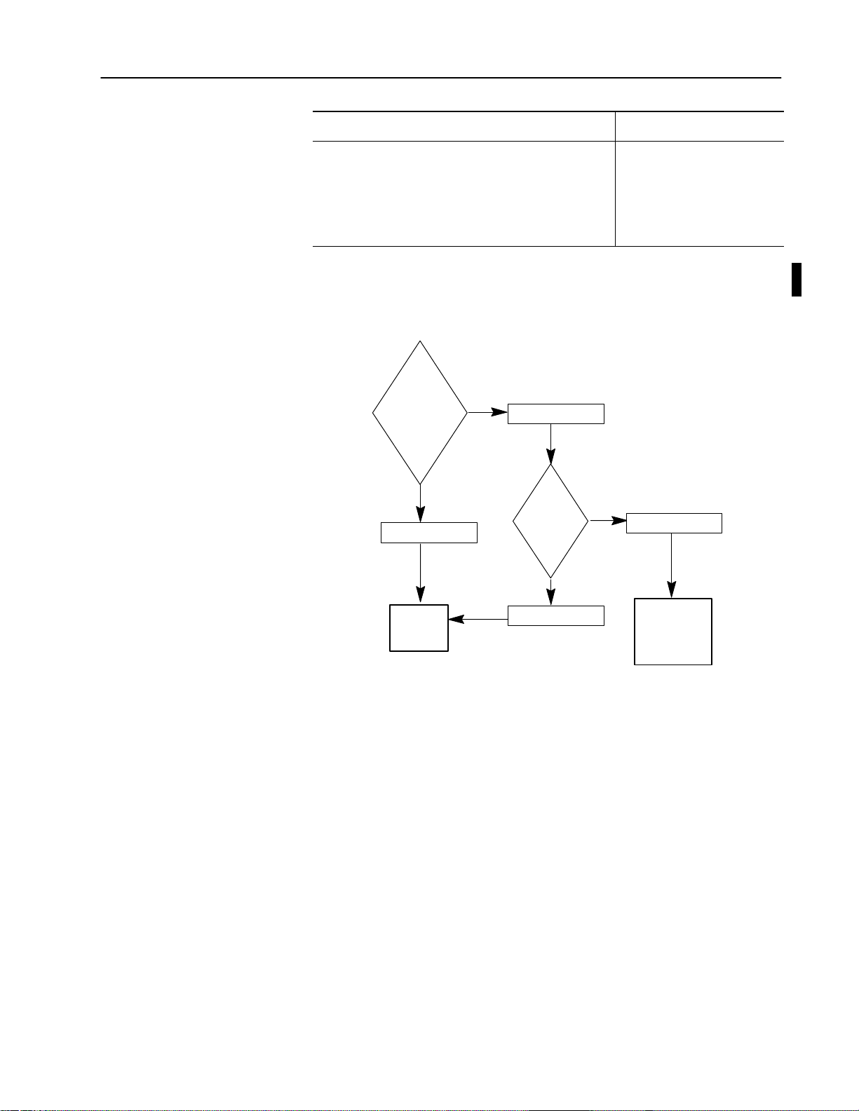
5. To continue or abort the installation, follow the flowchart below:
Continue
or
Abort
Installation
Abort
Enter: [Cntrl-C]
2–3Installing ODS
Continue
Press any key
Go to
Step 6
Msg:
Terminate
Batch Job
Y/N
No
Enter: [N]
Enter: [Y]
Yes
Computer
returns to
DOS
Important: Pay particular attention to the following when
you install ODS software:
• If you press any key to continue, files stored in the \IMC
directory are overwritten.
• If you are not sure this is acceptable, press [CTRL-C] to abort
installation.
• Check files stored in the \IMC directory.
• Copy any files that need to be saved to another directory; delete
the files from the \IMC directory.
• Start installation again.
Publication MCD-5.1 -August 1999
Page 17

2–4 Installing ODS
The installation utility installs the files from disk 1 onto the hard
disk and displays this message:
Phase 2 Installation will now be invoked.
If the message “Bad command or filename”
appears, it means that the DOS command
processor (COMMAND.COM) could not be located.
Make sure your PATH command includes the
directory that COMMAND.COM resides in. Then
re-start this Installation procedure.
See your DOS manual for further information.
Strike a key when ready . . .
6. Press any key to start Phase 2 of the installation utility.
The computer displays:
Copyright 1989-1999 Allen-Bradley Company
Installation program - Phase 2
Installing ODS for Model 9/Series (archive
version)...
When the installation utility finishes installing all of the files
from disk 1, the computer displays this message:
Insert Disk # 2
Strike a key when ready . . .
7. Remove disk 1 from drive A, and insert disk 2.
8. Press any key to continue the installation process.
The screen displays this message:
Installing Disk # 2
9. After all of the files from disk 2 are installed, repeat the process
for each of the remaining disks.
10.Select your options. ODS installs the products that you selected.
After you complete the installation process, the ODS displays
this message:
Insert Disk # 1
Press any key to continue...
11.Remove the floppy disk from drive A, and insert disk 1. Press
any key to continue.
The installation utility displays a message similar to this:
ODS supports most IBM 100% compatibles,
however, some use unusual video monitors.
Please select the type of computer this
version of ODS will be running on:
1) 100% compatible or Allen-Bradley
T35/T47/T50/T60
2) Allen-Bradley T45
3) COMPAQ Portable 386
Publication MCD-5.1 -August 1999
Enter selection (1/2/3):
Page 18

12.Select [1], [2], or [3], depending on the type of computer.
2–5Installing ODS
Choose selection
[1] if you are using an Allen-Bradley Series
6120, 6121, 6122, or 618X computer.
The installation utility configures ODS to the type of computer
selected. If the installation utility includes any update notices, it
displays the first page under this heading:
mm/dd/yy
PLEASE NOTE THE FOLLOWING ITEMS:
*
*
notice text
*
*
--MORE--
13.Read the first page, then press any key to display the next page.
14.Repeat step 13, displaying all the available pages. Press any key
to continue.
The installation utility displays this message:
If you would like to print the
above message, use the DOS command:
PRINT a:READ.ME
Strike a key when ready . . .
You cannot enter the DOS PRINT command during installation.
15.Press any key to continue.
The installation utility displays the message:
To run ODS, type “cd \imc”,
then type “imc”.
IBM is a registered trademark of
International Business Machines Corporation
COMPAQ is a registered trademark of
Compaq Computer Corporation
Done...Please remove Disk 1 from the drive.
You see the C:\IMC> prompt.
16.Remove disk 1 from drive A.
Store the master ODS disks in a safe location. You can now print
the READ.ME file.
Publication MCD-5.1 -August 1999
Page 19

2–6 Installing ODS
Using Windows NT
Important: This procedure assumes that drive A is a 3.5-inch
floppy-disk drive and that drive C is a hard-disk drive.
If the drive designations on your computer are different,
substitute the appropriate designations.
1. Turn on the computer and insert ODS disk 1 into drive A.
2. Click the Windows NT Start button and select Run. A similar
box appears:
Modifying the CONFIG.SYS File
If the correct path does not appear by default in the Open:
pulldown menu box, type the correct path (e.g., a:\install a: c:,
where a: is the source drive and c: is the destination drive).
3. Press [ENTER]
The computer begins to execute the installation utility. Refer to
steps 4 through 15 in the Using DOS section (beginning on
page 2–2) for further instructions on installing your ODS
software.
If you are using a DOS–based system, you can optimize ODS
performance, by modifying your CONFIG.SYS file.
Important: 8100 HS110 software does not require you to add the
line ‘DEVICE=DF1DRV.SYS’.
1. Modify the CONFIG.SYS file, if necessary, to include these lines:
BUFFERS=25
FILES=20
DEVICE=DF1DRV.SYS
The record DEVICE=DF1DRV.SYS enables the DF1
communication driver to transfer files between ODS and the
servo controller.
Publication MCD-5.1 -August 1999
Page 20

When selecting any other CONFIG.SYS commands, be aware of
the memory requirements.
2. Reboot the computer to read the data from this file.
2–7Installing ODS
Modifying the AUTOEXEC.BAT File
Removing the ODS Software
If you are using a DOS–based system, you can directly start ODS.
You must modify the PATH command in the AUTOEXEC.BAT file
by adding this entry to the path:
;C:\IMC
If you want ODS to start automatically when you turn on the
computer, add this entry to the last line of the AUTOEXEC.BAT file:
IMC
Refer to the computer’s DOS manual for further instructions.
If for any reason you need to remove the ODS software from the
computer’s hard disk, use the following procedure:
Important: This procedure assumes that the floppy-disk drive is
drive A and the hard-disk drive is drive C. If the drive
designations on your computer are different, substitute
the appropriate designations.
Important: Before you remove the ODS software from the hard
disk, back up any projects you need to save, then delete
all of the projects.
1. Insert ODS disk 1 in floppy-disk drive A.
2. If you are at the
a:
C: prompt, type:
and press [ENTER].
3. At the prompt, type:
a:remove
and press [ENTER].
The removal utility displays this message:
Publication MCD-5.1 -August 1999
Page 21

2–8 Installing ODS
4. Select the drive that contains the ODS software. For this
example, select drive C and press
[ENTER].
The arrangement of the list may vary slightly from what
currently appears on your screen. The removal utility displays a
message similar to this:
The menu highlights the installed ODS software and ghosts
unavailable software. Select the control family you want to
remove or ALL controls for all of the installed ODS software.
5. Select a control type.
If you selected a 9/Series control, this screen appears:
Publication MCD-5.1 -August 1999
Page 22
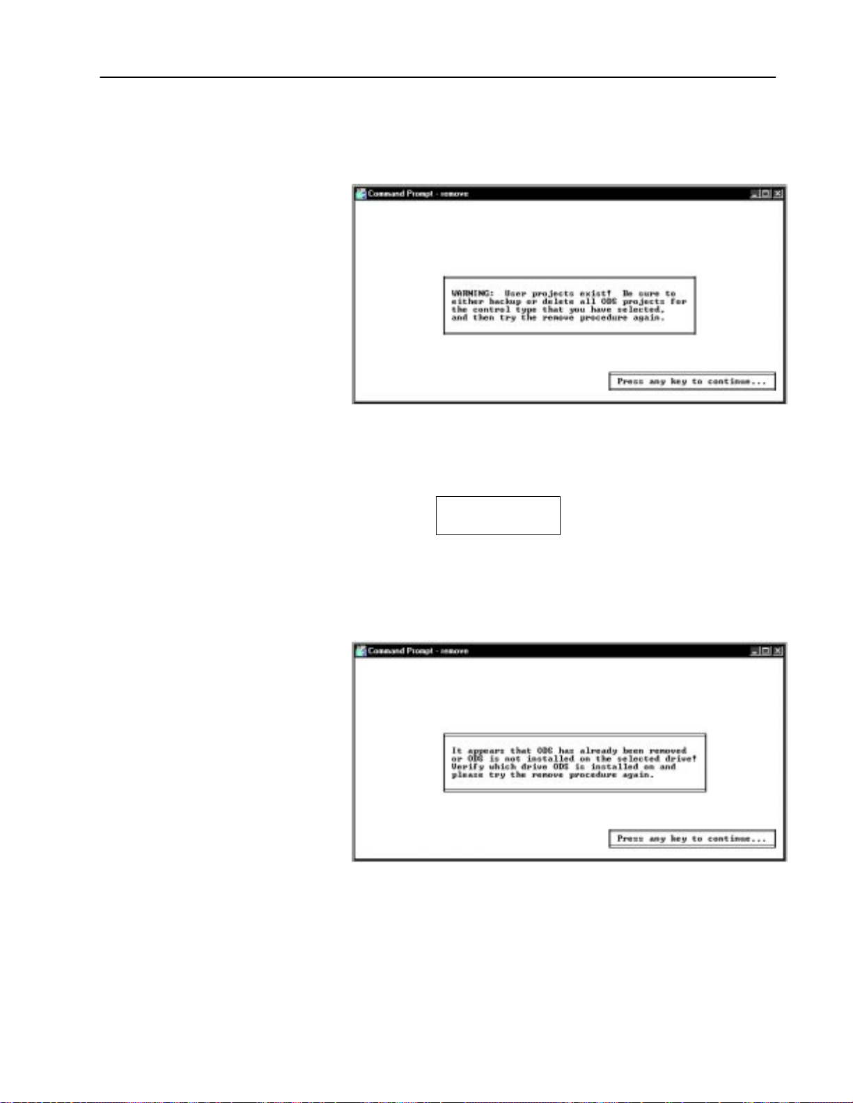
6. If applicable, select an application type.
If all projects or files have not been deleted from a specific
application before being removed, this warning appears:
With the appearance of this screen, the removal utility begins
deleting files from the hard disk:
2–9Installing ODS
Removing ODS
The removal utility looks for a particular list of files and
directories. If it cannot find the file or directory that it is looking
for, the removal utility displays a message similar to the
following:
This message does not indicate that the removal process is
proceeding incorrectly. It indicates the condition of the directory
and is for your information only.
Publication MCD-5.1 -August 1999
Page 23

2–10 Installing ODS
When removal is complete, the removal utility displays this
message:
Removal Complete
Press any key to continue . . .
7. Remove the disk from the floppy-disk drive.
What to Do Next
Chapter 3 tells you how to use the ODS software.
END OF CHAPTER
Publication MCD-5.1 -August 1999
Page 24

Chapter 3
Getting Started with ODS
Chapter Objective
This chapter tells you how to create and edit these types of ODS
files:
• machine configuration
• machine interface
• machine motion control
If you want to: See page:
get started using ODS 3-1
use pulldown menus 3-4
use online help 3-5
read the status line 3-7
define projects 3-8
define applications 3-9
define utility 3-10
use directory 3-10
enter file and project names 3-11
interpret error messages 3-12
use the [ESC] key 3-12
edit ODS 3-12
know what to do next 3-12
Getting Started
To begin:
Using Windows
1. Select MSDOS Command Prompt under the Programs option
of the Windows NT Start menu.
2. At the DOS prompt, type:
IMC [ENTER]
If the message Bad command or filename appears, this is an
indication that the PATH command in the AUTOEXEC.BAT file
does not contain the directory \IMC.
3. If this is the case, type:
cd IMC [ENTER] IMC [ENTER]
ODS displays the welcome screen.
Publication MCD-5.1 -August 1999
Page 25

3–2 Getting Started with ODS
Continue to step 4 on page 3–3.
Using DOS
1. Turn on the computer and boot DOS.
IMC was included as the last record in the AUTOEXEC.BAT
If
file, ODS starts automatically when you turn on the computer.
2. At the DOS prompt, type:
IMC [ENTER]
If the message Bad command or filename appears, this is an
indication that the PATH command in the AUTOEXEC.BAT file
does not contain the directory \IMC.
3. If this is the case, type:
cd \IMC [ENTER] IMC [ENTER]
ODS displays a similar welcome screen.
Publication MCD-5.1 -August 1999
Page 26

4. Press any key to continue. A screen similar to this appears:
ODS installs the DOS print driver in RAM, which allows you to
download files to a printer.
Important: You must first install the print driver to be able
to print files from ODS menus.
3–3Getting Started with ODS
If the print driver is: then:
already installed the above screen appears for a moment and then is
replaced by the ODS top level screen (page 3-4)
not installed ODS asks you to select a device name:
Name of list device [PRN]:
5. Select a device name.
If you want to use: then:
the default device name press [ENTER]
a different device 1. Type a device name, for example:
•LPT1
•LPT2
•LPT3
2. Press [ENTER]
•COM1
•COM2
•AUX
Refer to DOS documentation for more information about printer
device names.
6. However, if the screen is distorted, follow this procedure:
a. Exit ODS.
b. At the DOS prompt, type:
MODE BW80 [ENTER]
c. Reboot ODS following the instructions on page 3–1 or
3–2. Examine the screen. If the screen is clear, we
suggest that you add the command MODE BW80 to the batch
file, IMC.BAT.
Publication MCD-5.1 -August 1999
Page 27
3–4 Getting Started with ODS
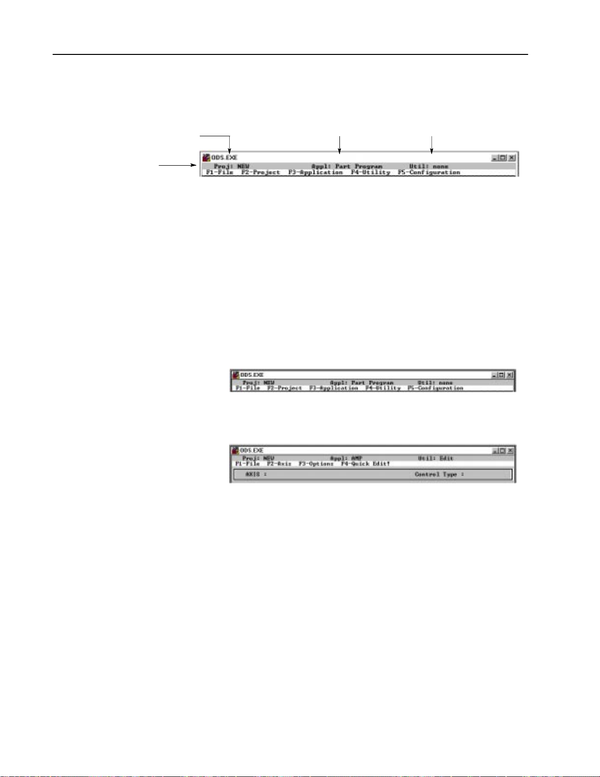
ODS displays the first line of its menu.
the Project
A project is a directory you create to
store files for a particular controller or job.
status line
Using Pull-down Menus
the Application
An application is a group of programs
used for creating and managing files.
the Utility
A utility is one of the programs
in an application.
The first line of the ODS screen layout (referred to as the status
line) identifies the project, the application, and the utility.
If a project, an application, or a utility is not active, the word
none appears in the corresponding space in the status line.
The second line of the ODS screen is the menu bar. The menu bar
identifies the pull-down menus. Select the functions you wish to
perform from these menus. The active application and utility
determine which menus are listed. For example, in this screen the
top-level menu bar includes five choices.
In contrast, the menu bar for the 9/Series AMP editor utility includes
four choices for a single process system:
Some menu choices are:
• highlighted (available for selection)
• darker or ghosted (unavailable for selection)
ODS automatically enables and disables menu choices according to
the operation that it is performing and its current status. For
example, the F3-Application menu is not available unless a project is
created or selected. Similarly, you must select an application before
the F4-Utility menu becomes available.
Publication MCD-5.1 -August 1999
Page 28
3–5Getting Started with ODS
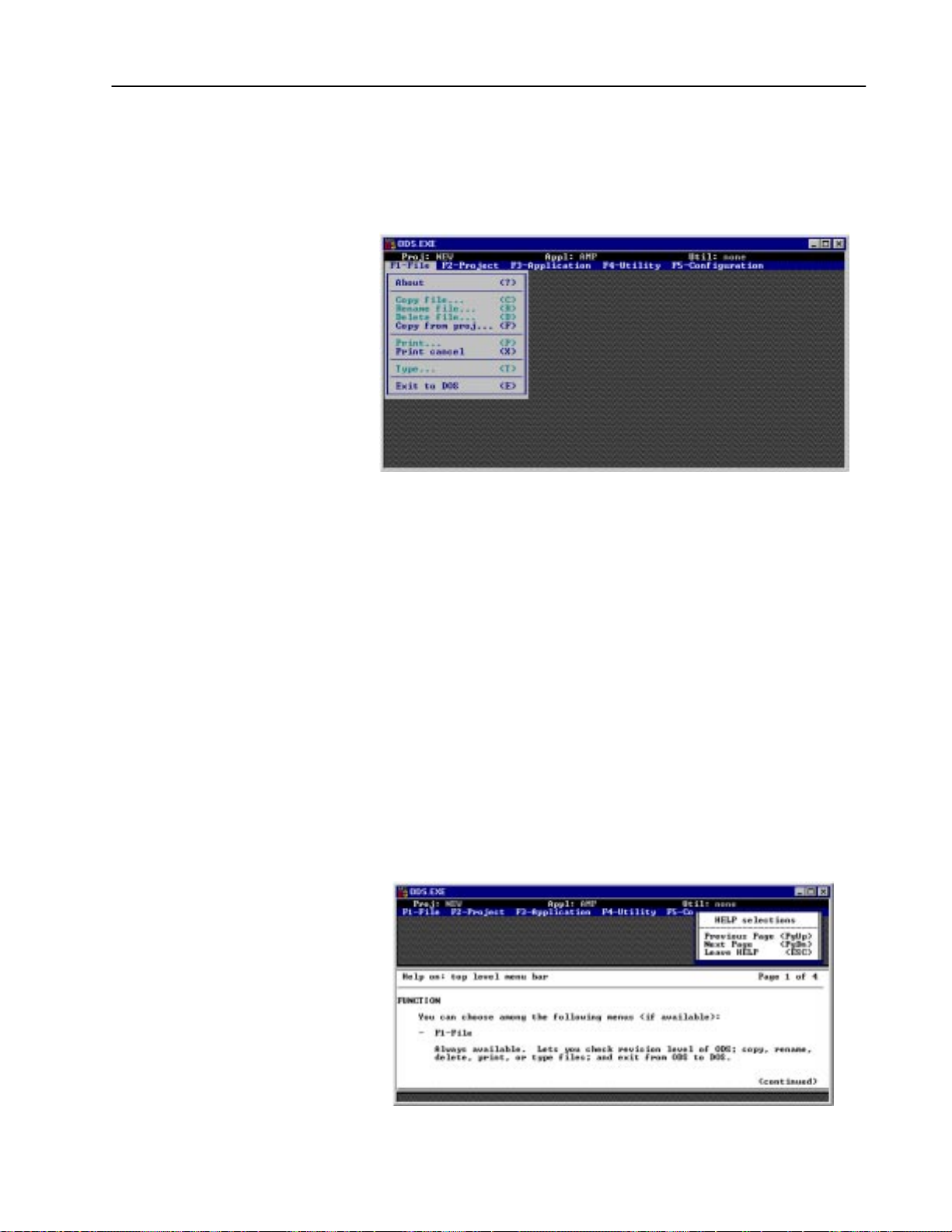
Pulling Down a Menu
To pull down a menu, press the function key indicated on the menu
bar. ODS then displays it on the screen. For example, when you
press [
F1] to pull down the F1-File menu, you see this screen:
Selecting a Menu Option
Using Online Help
There are two ways to select the menu options:
• Press the key indicated between the parentheses on the menu.
For example, press
? to select the About option.
• Use the arrow up [↑] or arrow down [↓] keys to highlight the
option desired, then press [
ODS online help is context sensitive; therefore, any time that you
request help, ODS provides a relevant help message. Online help is
structured into the ODS software, and is available only if you install
it. The online help menu appears on the right side of the screen just
below the F5-Configuration heading.
1. To request help, simultaneously hold down the [
key([ALT-H]), then release.
During the ODS installation process, ODS presents update
notices as a series of help messages. The help portion of the
screen describes how to use the menu for the help messages.
ENTER].
ALT] key and [H]
This help message contains some introductory information about ODS. Read it carefully.
Publication MCD-5.1 -August 1999
Page 29
3–6 Getting Started with ODS
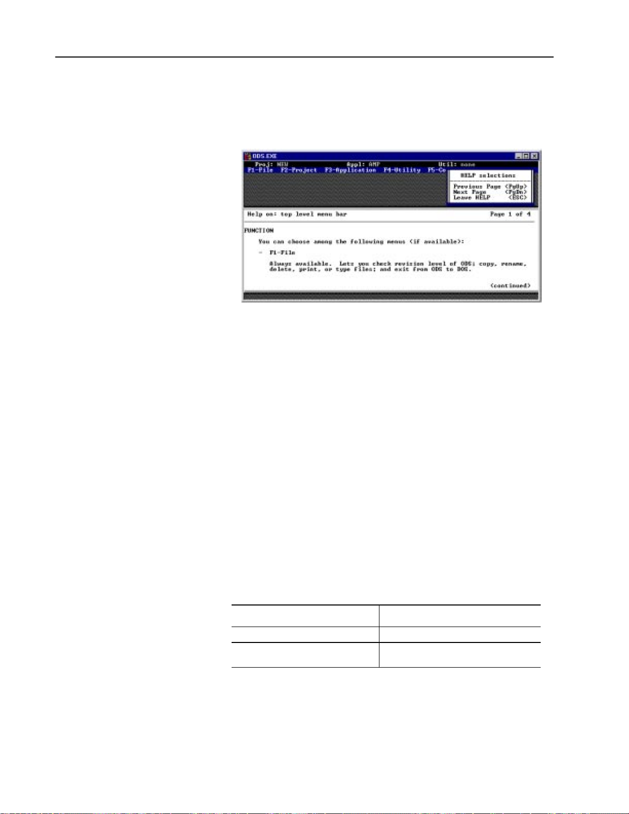
The box at the upper right of the screen below tells you how to
display other pages of the help screens. If there is more text in the
help message than can fit in one window, you can access the next
page of help by selecting the [
PgDn].
Notice that the Previous Page [PgUp] choice is ghosted, indicating
that it is not available for selection. Since the page of help text
displayed is the first page, there are no previous pages to access.
When you select [
PgDn] to move to the second help page, the [PgUp]
choice becomes available.
2. Press the [
ESC] key to clear the help text from the screen.
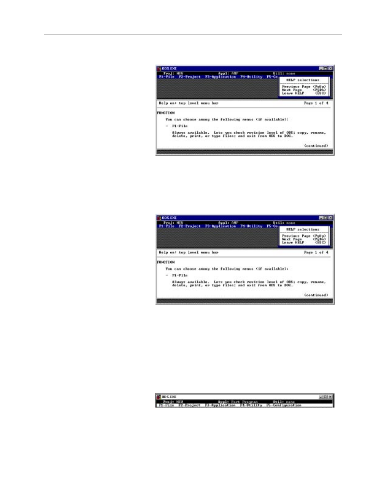
• At the top of each help screen there is a heading that
identifies:
– the topic of the screen
– the current page
– how many pages there are in the help text
• Most help text is divided into sections, with each section
indicated by a heading in the text.
• If the body of text for a heading within the help text is
continued on the next page of help text, the word (continued)
appears at the bottom of the page.
Help screens are available for each of the top-level entries (F1-File
through F5-Configuration) in the menu bar.
When you select: then:
F1File from the menu heading the selection is highlighted
[ALTH] the help messages that appear describe the
entries contained in the F1File menu
Publication MCD-5.1 -August 1999
Page 30
3–7Getting Started with ODS
Refer to the example below:
When you select a specific function, use the arrow up [↑] or arrow
down [
[
↓] keys and highlight the desired entry. When you enter
ALT-H], a help message appears describing the functional details of
the selected entry. For this example, the help messages are for the
Copy file entry.
Reading the Status Line
Additional help messages are available for other ODS screens. If no
help is available, ODS displays:
Sorry, n o further help is available.
The status line of the ODS screen shows the active Project,
Application, and Utility. Figure 3.1 illustrates the way that ODS is
organized by project, application, and utility.
Publication MCD-5.1 -August 1999
Page 31

3–8 Getting Started with ODS
Figure 3.1
ODS Organization By Project, Application, and Utility
Projects
Applications
Utilities
PROJ1 PROJ2 PROJ3 PROJ4 PROJ5
Text
Edit
I/O
Assignments
AMP
Edit
Document
PAL
Ladder
Editor
Document
Module
Compile
Module
Build
Program
Monitor
Program
Message
Editor
Edit
Build
Config
Display
Page
Editor
Xref
Build
Config
MML
MML
Syntax
Edit
Compile
IMC File
Management
Data
Management
Edit
Document
Part
Program
File
Management
Upload Download
Edit
AMP
MML
PAL & I/O
Part
Program
AMP
MML
PAL & I/O
Part
Program
Publication MCD-5.1 -August 1999
Project
ODS creates configuration and interface files for the controller and
machine, and organizes these files into projects as shown in
Figure 3.2. You can compare a project to a file storage area for a
particular motion controller and machine application.
Page 32

Figure 3.2
Project Organization
PROJECT
NAME
CONTOL
TYPE
COMMUNICATION
MODE
CONTROL
FIRMWARE
REVISION
PROJECT
DIRECTORY
INTEGRATORS
NAME
IDATE
DESCRIPTION
AND
COMMENTS
You can create a project directory for each motion
controller/machine system. This lets you use ODS on many different
motion controller and machine applications.
The F2-Project pull-down menu is used to manage project
directories. You can:
3–9Getting Started with ODS
•log general information •rename projects
•create new projects •delete projects
•select existing projects •back up projects to floppy disk
•copy projects •restore projects from floppy disk
Chapter 5 describes the functions of the F2-Project menu.
Application
Use the F3-Application pull-down menu to select the application that
you need for your project (as shown in Figure 3.3 using a 9/Series
ODS package).
Publication MCD-5.1 -August 1999
Page 33

3–10 Getting Started with ODS
Applications
machine configuration
Figure 3.3
Application Organization
Applications
machine interface
Applications
machine motion control
Each project contains several applications that include these files:
• machine configuration
• machine interface
• machine motion control
You can access the F3-Application pull-down menu when you create
or select a project. The type of applications available for a project
depends on the controller that is being integrated to the machine.
Using Directories
Utility
The F4-Utility pull-down menu lets you select the utility needed for
your application. The utilities that are available depend on the active
application. For example, the AMP application includes:
• an editor utility that lets you create and edit AMP parameter files
• a document utility that creates lists of the parameter values in an
AMP parameter file
The file directory is one of the ODS management tools. All
directories have the same basic format as in the screen shown below,
but each lists different types of files, depending on the active
application.
Publication MCD-5.1 -August 1999
Page 34

3–11Getting Started with ODS
For example, while one directory lists AMP parameter files, another
might list PAL source programs, and another might list Projects.
All ODS directories share two common characteristics:
• One page of a directory can list as many as 66 items. If a
directory contains more than 66 items, it displays on more than
one page. To access the second page of a directory, press the
[
PgDn] key. To access the previous page, press the [PgUp] key.
• The two ways to select items from a directory are:
Entering File and Project Names
- Use the arrow keys to highlight an item, then press
A highlight appears in the directory when an arrow key is
pressed.
- Type in the name of the item and press [ENTER]. A box for entry
of the item name appears above the directory when a key other
than an arrow key is pressed.
When ODS asks for a file or project name, the name you enter can:
[ENTER].
• contain no more than 8 characters
• contain letters A-Z and numbers 0-9
• contain any of these:
! @ # $ % & ( ) – _ { } ’
The system does not accept spaces in the filename. However, you
can use the underscore (__) as a substitute for a space. For example,
the name FILE 1 is illegal, but the name FILE_1 is legal.
If you enter a file or project name that does not meet these
conditions, ODS displays an error message and gives you another
opportunity to enter the name.
Publication MCD-5.1 -August 1999
Page 35

3–12 Getting Started with ODS
Interpreting Error Messages
Using the [ESC] Key
Exiting from ODS
If you make a mistake while entering a file name, selecting an
option, or performing some other task, ODS displays a message
giving information on the situation. On color monitors, these
messages appear in red boxes.
Press
[ALT-H] to request on-line help if you need more information
about an error message.
If you decide to discontinue an operation in ODS, pressing the
key usually cancels the operation. In most cases, pressing [ESC]
returns you to the previous screen.
You can exit ODS and return to DOS by following this procedure:
1. Display the top level screen.
2. Pull down the F1-File menu and select the
Exit to DOS option.
[ESC]
• The computer clears the screen and displays the DOS prompt.
• ODS saves the names of the last active project and
application, and automatically activates them the next time
you start ODS.
What to Do Next
Publication MCD-5.1 -August 1999
Chapter 4 tells you how to configure the ODS software.
END OF CHAPTER
Page 36

Configuring ODS
Chapter 4
Chapter Objective
This chapter tells you how to use the five functions available under
the F5-Configuration menu. These functions include how to:
• specify the text editor
• use the keyboard setup
• configure your serial communication device
• configure your print device (Windows NT only)
• turn the beeper option On and Off
• turn the verify option On and Off
• execute DOS commands when you are in ODS
If you want to: See page:
specify the text editor 4-1
use the keyboard setup 4-2
configure your serial communication device 4-3
configure your print device 4-4
turn the beeper ON/OFF 4-4
turn the verify feature ON/OFF 4-5
execute DOS commands from within ODS 4-6
know what to do next 4-6
Specifying the Text Editor
Some applications and utilities require the use of a text editor that
you must install. To use this text editor in ODS, specify the path and
file name with the F5-Configuration menu. This lets ODS activate
the text editor option.
Important: You must supply the text editor and install it on the
computer’s hard disk.
1. To access the text editor setup, pull down the F5-Configuration
menu.
2. Select the
ODS asks for the DOS path and file name of the text editor.
Text editor setup option.
Publication MCD-5.1 -August 1999
Page 37

4–2 Configuring ODS
If the text editor name was entered previously, the name appears
in the
Enter Name box on the screen.
3. If the text editor name needs to be changed or if there is no name,
type in the DOS path and file name for the text editor and press
[ENTER].
Assume, for example, that you are using Edit (a text editor
supplied with DOS) and that it is stored in a file named
EDIT.COM in a directory named DOS.
Important: You can specify any text editor; however,
remember that you must store and supply this
editor in the computer’s memory so that ODS
can find it. Refer to your DOS documentation
for more information about specifying path and
file names.
Keyboard Setup
4. To set up the text editor, type:
\dos\edit.com
5. Press [ENTER].
ODS stores the path and file name entered and returns to the
top-level menu bar.
ODS lets you select the language keyboard that is being used on your
personal computer. A checkmark (
√) indicates the active selection.
You can choose a new keyboard type from any of the other
selections.
1. Select the
Keyboard setup option from the F5-File menu.
ODS displays this box:
Publication MCD-5.1 -August 1999
2. Using the arrow keys, make a selection and press [ENTER].
Page 38

4–3Configuring ODS
Configuring the Serial Communication Setup
ODS allows you to configure the serial communication baud rate.
Use the
Serial comm setup.
[F5]–Configuration pulldown menu to access
Use this procedure to configure your serial communication device:
1. Select the
[F5]–Configuration menu. The following list box appears:
Serial comm setup option from the
Select the appropriate baud rate for your serial communication
device. To abort this activity, select
<ESC>.
2. If you are using Windows NT, the following list box appears after
you select the appropriate baud rate for your serial
communication device:
Select a serial communication port that is appropriate for your
system. To abort this activity, select
<ESC>. For DOS and
Windows 95 operating systems, make this selection in the DF1
device driver setup in the CONFIG.SYS file.
Once your selections are made, the configuration menu
disappears, but ODS saves your selections as your default settings
whenever ODS is started.
Publication MCD-5.1 -August 1999
Page 39

4–4 Configuring ODS
Configuring Print Device (Windows NT only)
If your are using Windows NT, ODS allows you to select your
default printer from a list of printers that are currently available to
your system. Use the
Print device setup.
[F5]–Configuration pulldown menu to access
Use this procedure to select your print device:
1. Select the
[F5]–Configuration menu. The following list box appears:
Print device setup option from the
Select the appropriate baud rate for your serial communication
device. To abort this activity, select
<ESC>.
Turning the Beeper ON/OFF
2. Select the appropriate print port for system. A checkmark
appears next to the current active choice. After you select a print
device, ODS saves it and makes this the default printer whenever
ODS is started. To cancel this selection, press
<ESC>.
ODS has a beeper that warns you when you press an illegal key or
when you attempt something that is not allowed. The
F5-Configuration menu lets you decide whether or not to use the
beeper.
Use this procedure to set the beeper:
1. Select [
F5] and pull down the F5-Configuration menu.
You can set the beeper to ON or OFF. A checkmark appears next
to the current active choice. If this is the first time ODS has been
configured, the check is next to
Beeper O N . After you make a
choice, ODS saves it and puts the beeper in that state whenever
ODS is started.
2. Select either
Beeper O N or Beeper OFF .
Publication MCD-5.1 -August 1999
The configuration menu disappears, but the beeper is set
according to the choice you made.
Page 40

4–5Configuring ODS
Turning the Verify Feature ON/OFF
When the verify feature is set to ON, ODS displays a screen when you
select the Delete file option:
To delete a file, select [Y]. If you select [N], ODS aborts the delete
operation. This gives you the opportunity to cancel a delete
operation after selecting it.
If the verify feature is OFF, ODS does not display the
this file?
box before deleting a file.
OK to delete
The F5-Configuration menu lets you turn the Verify feature ON or
OFF. Use this procedure to configure the
Verify feature:
1. Select
[F5] and pull down the F5-Configuration menu.
Notice that there are two choices for
Verify ON or Verify OFF.
A check mark appears next to the current active choice. If ODS
is being configured for the first time, the checkmark appears next
to Verify ON.
2. Select either
Verify O N or Verify OFF.
After you make a choice, ODS saves your selection, and puts the
Verify feature in that state whenever ODS is started up.
The configuration menu disappears, but the Verify feature is
turned ON or OFF according to the choice you made.
Publication MCD-5.1 -August 1999
Page 41

4–6 Configuring ODS
Executing DOS Commands from within ODS
What to Do Next
Use the following procedure to enter the DOS shell and execute
DOS commands without exiting ODS.
1. Select [
2. Select the
F5] and pull down the F5-Configuration menu.
Enter DOS Shell option.
The ODS screen disappears, and this prompt appears:
O.D.S. - Type EXIT to quit>
When this prompt appears, DOS commands can be entered and
executed.
3. To return to ODS, type:
EXIT
4. Press [ENTER].
The ODS screen reappears.
Chapter 5 tells you how to use the ODS software for project
management.
END OF CHAPTER
Publication MCD-5.1 -August 1999
Page 42

Chapter 5
Using ODS for Project
Management
Chapter Objective
This chapter tells you how to use ODS for project management
activities such as creating a new project, opening an existing project,
and selecting a utility. Other functions of the project management
feature are listed below.
A project is a directory that stores configuration, interface, and
motion control files for a particular control or application. You
cannot access an application until you have selected or created a
project.
The F2-Project menu provides options for creating and managing
project directories. In this chapter you learn how to use the
F2-Project pull-down menu to perform these functions:
If you want to: See page:
create a new project 5-1
open an existing project 5-7
display project information 5-8
change project information 5-9
copy a project 5-12
rename a project 5-15
delete a project 5-16
back up a project on floppy disk 5-17
restore a backedup project from floppy disk 5-19
select an application 5-21
select a utility 5-22
know what to do next 5-22
Creating a Project
In this section we assume that you started an ODS session as
described in Chapter 3.
To create a project:
1. Press [
F2] and pull down the F2-Project menu.
Publication MCD-5.1 -August 1999
Page 43

5–2 Using ODS for Project Management
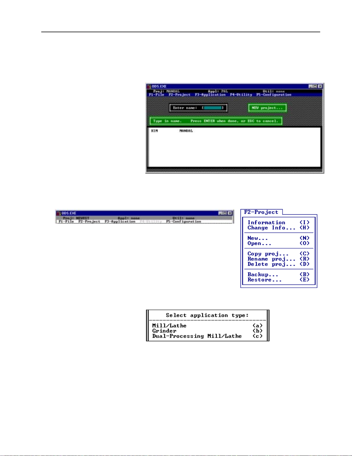
2. Select the New option.
ODS displays the message
New project and a directory of
existing projects.
3. Select a name for the new project and press[ENTER] to continue,
or press
[ESC] to cancel.
If ODS accepts the project name, it displays a box that asks what
is the control type of the new project. The order in which the
products are listed may vary slightly from what currently appears
on your screen.
A list similar to this appears:
For example, if you want to select an IMC 120 project, enter (b)
for the IMC 120 option. This choice determines which
applications ODS makes available for the project.
Publication MCD-5.1 -August 1999
Page 44

4. Select a control type.
If you select one of the 9/Series controls, a similar screen
appears:
5. If applicable, select an application type. For this example, we
chose
(a).
ODS asks you to determine the type of communication required
for your control.
5–3Using ODS for Project Management
Important: For standard RS232 communication, select (C).
For use with the DH+ network, select
(D). If
you are using OCI, you can either select the
Ethernet
(E) or Control Serial Port (C) option.
Important: Accessing DH+ using DOS or Windows 95 with
your 9/Series control requires INTERCHANGE.
Accessing DH+ via Windows NT requires
RSLinx. Refer to Chapter 7 for more
information about the configuration menu flow
for INTERCHANGE and RSLinx with DH+.
Important: The Ethernet/OCI communication mode is only
available for the 9/260 and 9/290 CNCs.
Accessing Ethernet requires Windows NT and
RSLinx. Refer to Chapter 7 for more
information about the configuration menu flow
for INTERCHANGE and RSLinx with DH+.
Publication MCD-5.1 -August 1999
Page 45

5–4 Using ODS for Project Management
If your control type is 9/PC (the default selection for
Communication Mode is PC to 9/PC ), the following steps must
be completed:
A. Enter the location of the 9/PC host computer in the text box.
Important: The explanation of “Local” in step A. assumes
The host computer is the computer name on the network
where the 9/PC is installed. This name should typically be
20 characters or less. “Local” (or the name that you enter)
denotes the default location of your host computer where
your 9/PC is installed. Once you enter the location, select
[ENTER].
that ODS and 9/PC are installed on the same PC.
If your host computer is a computer that 9/PC
and ODS is not installed on, refer to page 6–12.
B. By default, CNC_1 will appear in the box as the 9/PC topic
name. This is the name of your selected CNC. If this topic
name is incorrect, enter a new name in the text box.
Publication MCD-5.1 -August 1999
Page 46

Project subdirectories are directories that are stored within the
project directory. They store the created configuration and
interface files.
ODS displays a list of alternative control firmware revision levels
and asks you to select one of the items. You can select:
• one of the revision levels listed
• the Read from control option to read the revision level of
the control that is connected to ODS. If no control is
connected to ODS, selecting this option results in an error
message
Select the appropriate option, as shown in the example screen:
5–5Using ODS for Project Management
ODS displays a box that asks for your name:
6. Type in a name and press [ENTER].
ODS stores the name and displays a box with the current date.
7. Press
[ENTER] if this date is correct. If you want to modify the
date, edit the text and press
[ENTER].
ODS stores the date and displays the first of two boxes that asks
for comments.
8. Type in any comments about the project and press [ENTER].
ODS stores the comments, then displays the other comment box.
Publication MCD-5.1 -August 1999
Page 47
5–6 Using ODS for Project Management
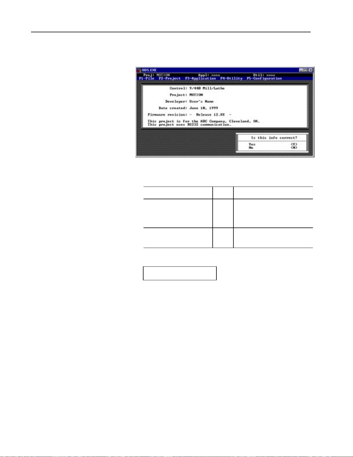
ODS displays the information screen and asks you to verify that it
is correct. For example:
9. Respond to the question: Is this info correct?
If the information displayed is:
correct [Y] ODS activates the project and displays
incorrect [N]
press: then:
the toplevel screen.
Notice that the status line indicates that
the newly created project is active.
repeat steps 5 - 8 or press [ESC] to
or
[ESC]
cancel the current operation.
ODS briefly displays the message:
Creating project sub–directories
Publication MCD-5.1 -August 1999
Page 48

5–7Using ODS for Project Management
Opening an Existing Project
You do not have to create a new project every time ODS is used.
ODS stores project files that you can open at any time.
Use this procedure to open an existing project:
1. Press [
2. Select the
F2] and pull down the F2-Project menu.
Open option.
ODS displays the message
Open project and a directory of
projects.
3. Select the project to be opened and press [ENTER]. If you want to
cancel, press
[ESC].
ODS clears the screen and displays the top-level menu. The
name of the most recently opened project appears on the status
line as the active project. This verifies that the project is open
and is active.
You are now ready to select an application for the project.
Publication MCD-5.1 -August 1999
Page 49

5–8 Using ODS for Project Management
Displaying Project Information
The Information option displays the following information about
the active project:
•control family •date created
•project name •firmware revision level of the control
•developer’s name •comments (2 lines)
This is the information entered when you create the project.
Use this procedure to display project information:
1. Press [
2. Select the
F2] and pull down the F2-Project menu.
Information option.
ODS displays the information for the active project. For
example:
Publication MCD-5.1 -August 1999
3. Press any key to clear the information display and return to the
top-level menu bar.
Page 50

5–9Using ODS for Project Management
Changing Project Information
The Change Info option lets you change the following information
for the active project:
•communication selection •date created
•developer’s name •comments (2 lines)
If you want to change the control type or the firmware revision, you
must create a new project. Use F2-Copy Project to copy the original
project.
1. Press [
2. Select the
F2] and pull down the F2-Project menu.
Change Info option.
ODS displays the communication menu:
3. To change your selection:
To: Select:
the serial port for standard RS232 communication (C)
the port for the Data Highway Plus network
the port for Ethernet/OCI communication
communicate with 9/PC, using your PC (P)
1
The configuration menu flow for the Data Highway Plus and Ethernet are in
Chapter 7.
1
1
(D)
(E)
Important: You can configure ODS to the DH+ network if the Data
Highway selection is not ghosted.
Publication MCD-5.1 -August 1999
Page 51

5–10 Using ODS for Project Management
If your control type is 9/PC, the following steps must be
completed:
A. Enter the location of the 9/PC host computer in the text box.
The host computer is the location that you will be uploading
and downloading files from. This name should typically be
20 characters or less. “Local” denotes the default location of
your host computer. Once you enter the location, select
[ENTER].
B. By default, CNC_1 will appear in the box as the 9/PC topic
name. This is the name of your selected CNC. If this topic
name is incorrect, enter a new name in the text box.
ODS displays a box that asks you to enter your name. The
current name is displayed in the box. For example:
Publication MCD-5.1 -August 1999
Page 52

5–11Using ODS for Project Management
4. Press [ESC] or [ENTER] to retain the current name, or type in a
new name and press
[ENTER].
ODS saves the name and displays a box that asks for the date.
The most recently entered date is displayed in the box. For
example:
5. Press [ENTER] to retain the current date, or type in a new date.
Press
[ESC] to cancel.
ODS stores the date and displays the first of 2 boxes that asks for
comments. The most recently entered comments are displayed in
the box. For example:
6. Press [ENTER] to retain the displayed comments, or type in a
new comments. Press
[ESC] to cancel.
ODS stores the comment and then displays the other comment
box.
7. Press [ESC] or [ENTER] to retain the displayed comments, or
type in a new comments and press
[ENTER].
ODS displays the information screen and asks if it is correct.
Here is an example display:
Publication MCD-5.1 -August 1999
Page 53

5–12 Using ODS for Project Management
8. Respond to the question: Is this info correct?
Copying a Project
If the information displayed is:
correct [Y] go on to another task
incorrect [N]
press: then:
repeat steps 5 - 8 or press [ESC] to
or
[ESC]
cancel the current operation.
You can copy files from an existing project as the basis for a new
project. Entire sets of files from an existing project of a compatible
type can be copied to either a new project or another existing project.
Use this procedure to execute the copy operation:
1. Press
2. Select the
[F2] and pull down the F2-Project menu.
Copy Proj option.
ODS displays the message,
Copy Project FROM and a directory
of projects.
Publication MCD-5.1 -August 1999
Page 54

5–13Using ODS for Project Management
3. Select the project that you are copying from the directory or press
[ESC] to cancel.
ODS displays the message,
Copy project TO and displays a
directory of projects that are compatible to the project chosen to
be copied from.
4. Select the project to which you are copying. You can enter a new
name or you can select an existing name from the directory. If
you enter a new name, ODS will ask you for information about
the new project that you going to copy to (see page 5–2, step
3.), and then go to step 6.
If you select: ODS displays:
an existing project to which to copy information about the selected project and
asks whether or not it is alright to overwrite
the existing project files with the copied files
This is an example screen:
Publication MCD-5.1 -August 1999
Page 55

5–14 Using ODS for Project Management
Notice that the WARNING box in the lower left corner appears only
if you try to overwrite the active project.
5. Respond to the question: OK to OVERWRITE this project?
If you want to:
overwrite the existing project file [Y]
keep the existing project file, unharmed [N]
If you selected: then ODS:
[No] again asks for the name of the project to be copied to
repeat step 4 or press [ESC] to cancel
[Yes] briefly displays the message:
Deleting project sub-directories
press:
ODS first creates new project subdirectories for the new project,
displaying the message:
Creating project sub-directories
ODS copies the project files from the selected source project to
the selected destination project, displaying the message:
Copying files
6. After entering the project information, ODS displays all of the
information typed in and asks if it is correct. For example:
Publication MCD-5.1 -August 1999
Page 56

7. Respond to the question: Is this info correct?
5–15Using ODS for Project Management
Renaming a Project
If the data is:
correct [Y] or [ENTER] go on to another task
incorrect or needs to be changed [N] ODS gives you another opportunity
press: then:
to enter data for each item.
ODS activates the project just created, and displays the main
menu. The status line indicates that the project just entered is
active.
This procedure lets you change the name of an existing project. This
option is highlighted only if there is at least one project stored in
ODS.
1. Press
2. Select the
[F2] and pull down the F2-Project menu.
Rename Proj option.
ODS displays the message
Rename project FROM and a
directory of projects.
3. From the directory, select the project to be renamed.
ODS displays the message
Rename project TO and the directory
of projects, and asks for the new project name to be given to the
project.
Enter name: [ ] Rename Project TO
Publication MCD-5.1 -August 1999
Page 57

5–16 Using ODS for Project Management
4. Type in the new name to be given to the selected project, then
press
ODS renames the project, then asks you to enter project
information. It also displays the information that was entered and
asks if it is correct.
[ENTER].
Deleting a Project
5. Respond to the question:
If the data is:
correct [Y] or [ENTER] ODS stores the information and
incorrect or needs to be changed [N] ODS gives you another opportunity
Is this info correct?
press: then:
returns to the toplevel screen.
to enter data for each item.
If you decide that it is no longer necessary to store a project on the
hard disk, you can delete the project by using this procedure:
1. Press [
2. Select the
F2] and pull down the F2-Project menu.
Delete Proj option.
ODS displays the message
DELETE project and a directory of
projects.
Publication MCD-5.1 -August 1999
Page 58

5–17Using ODS for Project Management
3. Select the project to be deleted and press [ENTER], or press [ESC]
to cancel.
ODS displays the information for the selected project and asks for
permission to delete it.
Backing Up a Project to Floppy Disk
Notice that the WARNING box in the lower left corner appears only
if you try to delete the active project.
4. Respond to the question:
If you want to:
keep the project [N] returns to step 3
delete the project [Y] displays this message:
press: then ODS:
OK to DELETE the project?
It does not delete the project, again displays the project
directory and asks for another selection.
Deleting project sub-directories
displays the main menu when the project is complete
ODS stores the files you created, including the configuration and
interface files, on the computer’s hard disk. The
Backup option of
the F2-Project menu lets you copy an entire project and all of its files
from the hard disk to a floppy disk(s).
After backing up a project to floppy, you can delete it from the hard
disk. This helps save space on the hard disk and helps avoid having
inactive projects in the directory.
Important: Be sure to initialize your floppy disks.
Publication MCD-5.1 -August 1999
Page 59

5–18 Using ODS for Project Management
Use this procedure to back up a project to floppy disk:
1. Press [
2. Select the
F2] and pull down the F2-Project menu.
Backup option.
ODS displays the message
BACKUP project and the directory of
projects.
3. Select the project to be backed up and press [ENTER]. Press [ESC]
to cancel.
ODS asks you which floppy-disk drive to send project files to:
4. Select one of the drives according to the computer’s
configuration, and press [
ENTER]. Press [ESC] to cancel.
The screen goes blank briefly and ODS activates the
ODS-supplied disk backup utility.
Important: The target drive is the floppy-disk drive to
which the project is being backed up. All files
on the floppy disk are deleted.
Publication MCD-5.1 -August 1999
Page 60

5. Insert the floppy disk into the drive then press any key.
CAUTION: The Backup option lets you save only
one project per floppy disk. At least one floppy per
!
The are files as they are being copied. When the backup is
complete, ODS displays the message:
6. Press any key and ODS returns to the top-level menu bar.
project is needed to back up more than one project and
some projects may require more than one floppy disk,
depending on the size.
Backup completed. . .
. . . remove floppy . . .
. . . label floppy disks...
5–19Using ODS for Project Management
Restoring a Backed-up Project
CAUTION: Although all project files have been
copied from the hard disk to floppy disk, nothing has
!
If necessary, a project that was backed up and deleted can be restored
from a floppy disk to the hard drive. Use this procedure:
1. Press [
2. Select the
ODS displays the message
floppy drive the project will be restored from.
been deleted from the hard disk. To delete the backed
up project from the hard disk, use the
procedure.
F2] and pull down the F2-Project menu.
Restore option.
RESTORE Project and asks which
Delete Proj
Publication MCD-5.1 -August 1999
Page 61

5–20 Using ODS for Project Management
3. Select the drive that will be used and insert the floppy disk that
contains the backed-up project into the selected drive.
If the project was backed up on a computer that is running a
version of DOS between 2.1 and 3.2 (inclusive), ODS reads the
project information from the floppy disk, displays it on the CRT,
and asks if it is permissible to restore this project. For example:
If the project was backed up on a computer using a version of
DOS or 3.3 or later, only the name of the backed-up project is
shown. If the project being restored has the same name as the
active project, ODS warns you that the files of the active project
will be overwritten.
4. Check the information displayed to be sure the right project is
being restored. If the project being restored has the same name as
the active project, ODS warns you that the files of the active
project will be overwritten.
Important: If the restored project has the same name as the
active project, the active project’s files are replaced with the files
from the floppy disk.
5. Respond to the question:
If you want to:
select another project because the
displayed project is not the correct one
restore the project [Y] ODS executes its Restore Utility and prompts you to continue the
press: then:
[N] return to step 1 and insert the correct floppy disk
Is this info correct?
procedure.
The files are listed as they are copied from the floppy disk to ODS.
When restoration is complete, ODS displays the message:
Restore completed
Publication MCD-5.1 -August 1999
6. Press any key to continue.
Page 62

5–21Using ODS for Project Management
Selecting an Application
After opening or creating a project, you can select an application in
which to work. ODS offers various applications for each of the
products:
• AMP — (IMC 110, 120, 121, 123, 9/Series, and 9/PC) lets you
create, edit, and document files of system parameter values
• PAL — (9/Series) lets you create, edit, document, and compile
PAL programs (machine interface ladder logic).
• MML — (IMC 110, 120, 121, and 123) lets you create a machine
interface, using English-like statements for axis motion and I/O
control
• I/O Assignments — (9/Series) lets you create, edit, and
document the I/O assignments for this control
• Part Programs — (9/Series and 9/PC) lets you create, edit and
download part programs (RS-274 format)
• Upload — lets you read AMP, MML, I/O Assignments, Part
Programs, and PAL files from the servo contro
ller
• Download — lets you send AMP, MML, I/O Assignments, Part
Programs, and PAL files from ODS to the servo controller
To select an application from the F3-Application menu:
1. Pull down the F3-Application menu and select one of the
applications listed.
ODS activates the application selected and displays its name on
the status line. For example:
PAL is the selected application
2. Once an application is selected, you can pull down the F4-Utility
menu to select a utility.
Publication MCD-5.1 -August 1999
Page 63

5–22 Using ODS for Project Management
Selecting a Utility
What to Do Next
After you select an application and its name appears on the status
line, you can pull down the F4-Utility menu and select a utility. The
utilities available depend on which application is active. Refer to
chapters specific to an application for a description of the
application’s utilities. The example screen is the F4-Utility for the
PAL application on a 9/Series control.
Chapter 6 describes ODS file management, including choosing,
copying, renaming, deleting, and printing files.
END OF CHAPTER
Publication MCD-5.1 -August 1999
Page 64
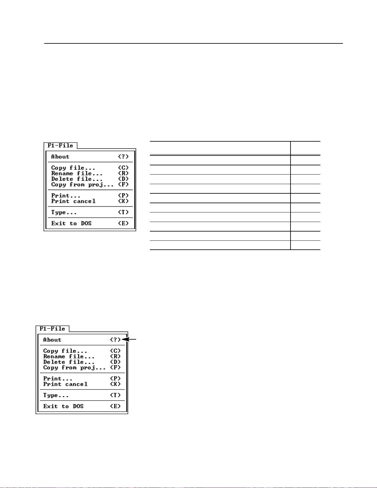
Chapter 6
Using ODS File Management
Chapter Objective
This chapter tells you how to use the common options of the F1-File
menu. The F1-File menu appears on the top-level menu bar, and on
the menu bars of several utilities. It provides options for handling
files in the active project and application. The F1-File menu options
vary depending on the active utility.
If you want to: See page:
display information about the active utility or about ODS 6-1
choose the file type within a PAL application 6-2
copy a file from a current project/application into another file 6-2
rename a file from a current project/application 6-3
delete a file from the current project/application 6-4
copy a file from another project to the active project 6-5
print a file from the active project/application 6-8
stop printing 6-9
display on the ODS screen a file from the active project/application 6-10
know what to do next 6-11
This chapter also describes other less common options and
applicable utilities.
Using ODS File Managment
When no utility is active, the
about ODS. When a utility is active and the
About option displays the information
About option is
available, it displays the information about the active utility.
To display the information:
1. Select [
2. Select the
F1] and pull down the F1-File menu.
About option.
ODS displays the appropriate information. For example, when no
utility is active, the About option displays a message like this:
The revisions of all control types loaded are displayed.
3. Press any key to return to the top-level menu.
Publication MCD-5.1 -August 1999
Page 65

6–2 Using ODS File Management
Choosing the File Type Within a PAL Application
Copying a File from a Current Project
When you are executing a PAL file management function on PAL
files, you must first select a PAL file type, such as Source, Build
List, Build Map, etc. The list of file types that are available to you
depend on the file management function that you are doing. File
type descriptions are in the operation and programming manuals.
To
Print or Type a file, you must run the Document utility under
F4-Utility menu.
Use the
Copy file option to copy one file of the active project/
application to a new file. A project and application must be active
for this option to be available. To C
1. Select [
2. Select the
F1] and pull down the F1-File menu.
Copy file option.
ODS displays the message
opy a file:
Copy From File and a directory of
files for the active project and application.
Publication MCD-5.1 -August 1999
3. Select the file from which you want to copy, or press [ESC] to
cancel.
• use the ARROW keys to move the cursor to the selected file,
then press [
ENTER], or
• type in the file name, then press [ENTER]
Page 66

ODS displays the message Copy To File and the directory of
files for the active project/application.
4. Type the new name of the file to which you want to copy, then
press [
ENTER], or press [ESC] to cancel.
ODS copies the specified file(s) and displays:
6–3Using ODS File Management
Renaming a File from a Current Project
Copying File
When the copy is complete, ODS returns to the original menu bar.
Use the
Rename option to change a file in an active
project/application. There must be a project and application active
for this option to be available. To
1. Select [
2. Select the
F1] and pull down the F1-File menu.
Rename file option.
ODS displays the message
Rename a file:
Rename From and a directory of files
for the active project/application.
Publication MCD-5.1 -August 1999
Page 67

6–4 Using ODS File Management
3. Select the file that you want to rename, or press [ESC] to cancel.
• use the ARROW keys to move the cursor to the selected file,
then press [
ENTER], or
• type in the file name, then press [ENTER]
ODS displays the message
for the active project/application.
Rename To and the directory of files
Deleting a File from a Current Project
4. Type in the new name for the file you are renaming, then press
[
ENTER].
ODS renames the specified file and displays:
Renaming File
ODS returns to the original menu when the operation is complete.
Use the
Delete option to delete a file in an active
project/application. There must be a project and application active
for this option to be available.
To
Delete a file:
1. Select [
2. Select the
ODS displays the message
F1] and pull down the F1-File menu.
Delete file option.
Delete File and a directory of files
for the active project/application.
Publication MCD-5.1 -August 1999
Page 68

3. Select the file that you want to delete, or press [ESC] to cancel.
• use the ARROW keys to move the cursor to the selected file,
then press [
ENTER], or
• type in the file name, then press [ENTER]
If the verify feature1 is enabled: then ODS:
6–5Using ODS File Management
Copying Files from Another Project
no deletes the file without checking for
confirmation
yes asks you if it is OK to delete the file
1
Refer to chapter 4.
4. If the verify feature is enabled, select the appropriate response:
If you want to: press: then ODS:
cancel the delete operation [N] cancels the delete operation and returns
to the original menu
delete the file [Y] briefly displays the message:
Deleting File
When the delete function is complete,
ODS returns to the original menu bar.
Use the Copy from proj to copy a file from the active application
of another project to the active project/application. To
proj:
Copy from
1. Select [F1] and pull down the F1-File menu.
Publication MCD-5.1 -August 1999
Page 69
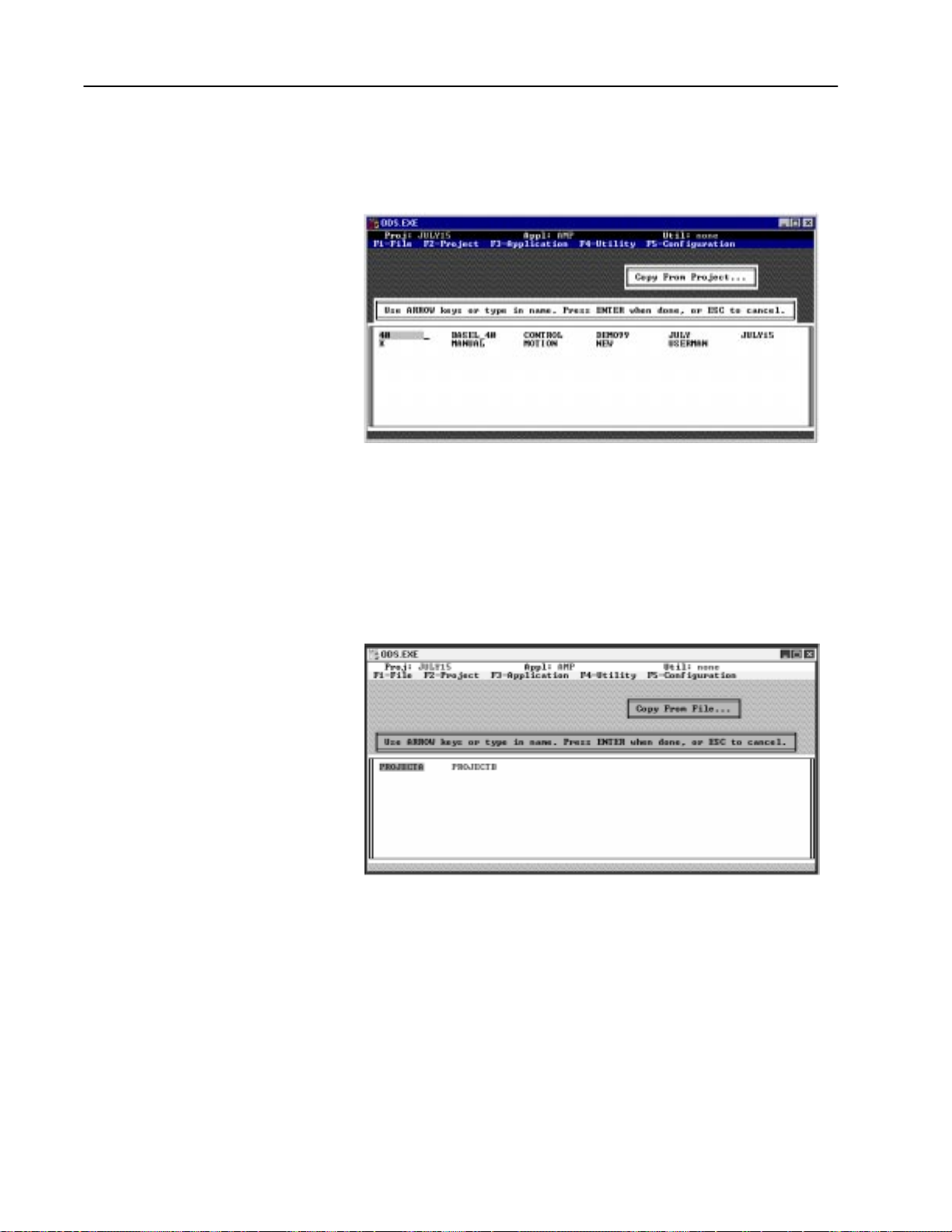
6–6 Using ODS File Management
2. Select the Copy from proj option.
ODS displays the message
Copy From Project and a directory
of applicable projects.
3. Select the project that contains the file that you want to copy, or
press [
ESC] to cancel.
• use the ARROW keys to move the cursor to the selected file,
then press [
ENTER], or
• type in the file name, then press [ENTER]
ODS displays the message
files for the active application and selected project.
Copy From File and a directory of
Publication MCD-5.1 -August 1999
Page 70

4. Select the file that you want to copy, or press [ESC] to cancel.
• use the ARROW keys to move the cursor to the selected file,
then press [
ENTER], or
• type in the file name, then press [ENTER]
ODS displays the message
for the active project.
Copy To File and a directory of files
6–7Using ODS File Management
5. Type the name of the file to which you want to copy (the
destination file), then press [
ENTER], or press [ESC] to cancel.
You must type a new name.
ODS copies the specified file(s).
Copying File
When the copy function is complete, ODS returns to the original
menu.
Publication MCD-5.1 -August 1999
Page 71

6–8 Using ODS File Management
Printing an ODS File
Use the Print option to send the contents of a file to a printer that is
connected to the computer being used for ODS development. Refer
to Chapter 3 for more information.
Using the Documentor
Prior to printing your ODS file, you must use the Documentor utility
to make it printable. The Documentor option is available for AMP.
PAL, and I/O Assignments applications only. To enable (unghosted)
the Documentor, you must have at least one file saved. To create a
documented version of a file:
1. Select [F4] and pull down the F4-Utility menu.
2. Select the Document option. A similar screen appears:
3. Select [D] to document the file. A similar screen appears:
Publication MCD-5.1 -August 1999
4. Select the appropriate sort type.
Once ODS documents the file, it prompts you to either document
another file or quit the AMP Documentor.
Page 72

Printing Your File
1. Verify that the printer is connected to the computer.
2. Verify that the DOS print spooler was properly invoked when
ODS was started.
6–9Using ODS File Management
3. Select [
4. Select the
ODS displays the message
F1] and pull down the F1-File menu.
Print option.
Print File and a directory of files
for the active project/application.
5. Select the file that you want to print, or press [ESC] to cancel.
• use the ARROW keys to move the cursor to the selected file,
then press [
ENTER], or
• type in the file name, then press [ENTER]
ODS outputs the file to the printer that is connected to the
computer.
Canceling a Printing Request
You can perform other ODS operations while printing is in
progress.
To cancel a printing operation that is in progress:
1. Select [
2. Select the
F1] and pull down the F1-File menu.
Print cancel option.
ODS stops sending data to the printer.
Publication MCD-5.1 -August 1999
Page 73

6–10 Using ODS File Management
Displaying an ODS File
Use the Type option to display a file on the ODS screen. Prior to
displaying your file, you must document it using the Documentor
utility. Refer to page 6–8 for more information. To
1. Select [
2. Select the
ODS displays the message
F1] and pull down the F1-File menu.
Type option.
Display File and a directory of files
Type a file:
for the active project/application.
3. Select a file to display, or press [ESC] to cancel.
• use the ARROW keys to move the cursor to the selected file,
then press [
ENTER], or
• type in the file name, then press [ENTER]
ODS displays the first page of the file on the ODS screen.
4. Press the [
view a previous page(s).
5. Press the [ESC] key to return to the original menu after viewing
the file.
This is an example page of an AMP document file:
PgDn] key to view the next page(s). Press [PgUp] to
Publication MCD-5.1 -August 1999
Page 74

6–11Using ODS File Management
What to Do Next
Chapter 7 tells you how to use the ODS software to configure
communication through various communication links.
END OF CHAPTER
Publication MCD-5.1 -August 1999
Page 75

Chapter 7
Using ODS Communication
Configuration
Chapter Objective
Refer to this chapter when you use ODS to configure communication
through these communication links:
• 1784-KL
• 1784-KT
• 1784-KTK1
• Serial port
• INTERCHANGE– this is a separate product used to
communicate to a CNC via DH+ if you are using DOS or
Windows 95. INTERCHANGE is a separate purchase and
installation. It is not packaged with ODS.
• RSLinx– this is a separate product used to communicate with a
CNC via DH+ or Ethernet if you are using Windows NT.
RSLinx is a separate purchase and installation. It is not packaged
with ODS.
Important: Use of Ethernet communication is only available on
9/260 and 9/290 CNCs.
If you want to: See page:
select a communication mode 7-2
preview the menu structure 7-3
configure a 1784KL 7-3
configure a 1784KT 7-3
preview KT address considerations 7-5
program from Data Highway Plus to Data Highway Plus
configure the 1784KTK1 7-7
preview KTK1 address considerations 7-8
preview 6122 considerations 7-8
preview IBM PC XT considerations 7-8
configure a serial port driver 7-9
use INTERCHANGE 7-10
use RSlinx for DH+ 7-11
use RSLinx for Ethernet 7-12
download AMP files for use with the 9/PC 7-12
set up the 9/PC host (server) computer 7-15
set up the ODS (client) computer 7-19
troubleshoot when using RAS communication 7-21
know what to do next 7-21
1
7-6
Publication MCD-5.1 -August 1999
Page 76

7–2 Using ODS Communication Configuration
Selecting the Communication Code
Communications
Communication Mode
Driver Type
Serial
Ethernet
DH+
INTERCHANGE
Initial project definitions include the new project’s name, control
family, and communication mode. Figure 7.1 describes the menus
you see when you select:
•communication
mode
Figure 7.1
Communication Selection Flow Chart
1. Select the desired communication mode:
- Control serial port using RS232 or RS422
- DH+ network, indirectly to the control, through the PLC backplane
- [ESC], which leaves the current communications type unchanged
Done
RSLinx for Ethernet
Refer to page 7-12.
2. Select the driver type that ODS will use to communicate over the Data
Highway+. This must match the type of hardware or communications
software installed in the system. The default is 1784KTK1 for IMC
controls, and INTERCHANGE for 9/Series CNCs using DOS or
Windows 95. For PCs using Windows NT, the default is RSLinx..
INTERCHANGE for DH+
(CNCs only)
Refer to page 7-10.
•processor type •driver type
RSLinx
KTK1, KL, KT, Serial
Processor Type
RSLinx for DH+
(CNCs only)
Refer to page 7-11.
3. Select the PLC processor type that ODS will communicate with
to transfer data to the IMC control:
- PLC 5/10
- PLC 5/12
- PLC 5/15
- PLC 5/25
- PLC 5/250
1784KTK1 Driver
(IMCs only)
Refer to page 7-7.
1784KL Driver
(IMCs only)
Refer to page 7-3.
1784KT Driver
(IMCs only)
Refer to page 7-3.
Serial Port
(IMCs only)
Refer to page 7-9.
Publication MCD-5.1 -August 1999
Page 77

7–3Using ODS Communication Configuration
Menu Structure
Configuring the required information for the various driver types as
shown in Figure 7.2 is identical for all of the menus:
• <SHIFTTAB> lets you review previous menus
• <TAB> previews the next menu
• <ALTT> exits from the configuration menu saving the data
• <ESC> exits without saving
Figure 7.2
Drive Type Menu
Configuring a 1784-KL
Configuring a 1784-KT
The 1784-KL module lets a T45 and T47 communicate with the
PLC-5 processor. The 1784-KL also provides DH+ to DH+
programming.
To configure the information for the 1784-KL module, select (B)
from the Driver Type menu (Figure 7.2). Figure 7.3 describes the
menu flow to configure the KL module.
The 1784-KT module provides access for DH to DH+ programming.
It only takes one slot in your programming terminal and provides
communication to all Allen-Bradley processors.
To configure the information for the 1784-KT module, select (B)
from the Driver Type menu. Figure 7.3 describes the menu flow
used to configure the KT module.
The communication driver is interrupt driven so that the serial port
must support hardware interrupts. On most machines, COM1 and
COM2 support these interrupts.
Publication MCD-5.1 -August 1999
Page 78

7–4 Using ODS Communication Configuration
Figure 7.3
Configuration Flow for the 1784KL or 1784KT
1784KT Driver Type
1784KL Driver Type
Port Type Desired
Address of Driver Card
DH+ Station Address of Terminal
DH+ Station Address
of Logic Controller
Baud Rate of Driver
Select the communications port that will be used for Data Highway Plus
1.
communications.
2.
Select the address of the driver card that will communicate over the
Data Highway Plus (PLC). This address must match the address selected
on the switch setting on the 1784KT module. Address range is 10 binary
digits for the 1784KL driver and six digits for the 1784KT driver. The
default value is 00001, 10000 for the 1784-KL, and 000011 for the 1784-KT.
3.
Select the station address of the ODS terminal on the Data Highway Plus.
Address range is from 0 to 77 (octal). The default value is 77.
Select the station address of the logic controller on the Data Highway Plus.
4.
Address range is from 0 to 77 (octal). The default is 02.
5.
Select the baud rate using the Data Highway Plus communications. The
default value is 2400 baud.
Connection Type Desired
Network Access
Bridge Address
IMC12x Rack Address
IMC12x Group Address
Handshake Delay
Select the type of connection used on the Data Highway Plus. Direct
6.
indicates only a logic controller and the ODS terminal are connected.
Multidrop indicates more than one logic controller and ODS terminal are
connected. The default selection is Direct.
7.
Select the network access, Local or Remote, when using the 1784KT
module. The default selection is Local.
8.
Select the local or remote bridge address. The address range is
0 through 376 (octal). The default value is 110.
9.
Select the IMC rack address. The address range is 0 through 7.
The default value is 0. IMC 12x includes IMC-120, IMC-121,
IMC-123, and IMC-123CR.
Select the IMC group address. The address range is 0 through 7.
10.
The default value is 0. IMC 12x includes IMC-120, IMC-121,
IMC-123, and IMC-123CR.
11.
Select the delay time between Block Transfer read/write requests and Block
Transfer read requests to get the status from the last BLT. The delay time
range is 0 to 9999 milliseconds. The default value is 2500.
Publication MCD-5.1 -August 1999
Page 79

7–5Using ODS Communication Configuration
KT Address Considerations
Memory
Address
(Hexadecimal)
A000:0000
A400:0000
A800:0000
AC00:0000
B400:0000
B800:0000
C000:0000
C400:0000
C800:0000
CC00:0000
D000:0000
D400:0000
D800:0000
A14 A19A18A17A16A15
OFF
ON
OFF
ON
ON
OFF
OFF
ON
OFF
ON
OFF
ON
OFF
OFF
OFF
ON
ON
OFF
ON
OFF
OFF
ON
ON
OFF
OFF
ON
Figure 7.4 lists the valid KT addresses.
Figure 7.4
Valid KT Addresses
Network Board Switch Settings
OFF
OFF
OFF
OFF
ON
ON
OFF
OFF
OFF
OFF
ON
ON
ON
ON
ON
ON
ON
ON
ON
OFF
OFF
OFF
OFF
OFF
OFF
OFF
OFF
OFF
OFF
OFF
OFF
OFF
ON
ON
ON
ON
ON
ON
ON
ON
ON
ON
ON
ON
ON
ON
ON
ON
ON
ON
ON
ON
Software
Address
(Binary)
000101
100101
010101
110101
101101
011101
000011
100011
010011
110011
001011
101011
011011
Where:
1 = Factoryset address
2 = Preferred addresses when readdressing the 1784KT board
3 = KT board in a COMPAQ 386 that uses a VGA card
4 = KT board in a computer that uses an EGA card
Publication MCD-5.1 -August 1999
Page 80

7–6 Using ODS Communication Configuration
Programming from DH+ to DH+
Programming from DH+ to DH+ provides access to devices on other
DH+ links that are attached to your DH+ link through a DH network.
These remote programming configurations are available with the
1784-KT and 1784-KL modules.
Figure 7.5 shows a possible programming configuration from DH+
to DH+.
Figure 7.5
Remote Programming Example
Programming
Terminal
DH+ DH+
Local Link
1785KA
Address
PLC5
Address
Remote Link 1
1785KA
Address
1785KA
Address
Remote Link 2
PLC5
Address
1785KA
Address
DH+DH+
Remote Link 3
PLC5
Address
These rules apply when you set up remote programming:
• The PLC-5 processor on one DH+ link and a PLC-5 processor on
another DH+ link can have the same address.
• The programming terminal can be on any link.
• Address 77 octal is an illegal bridge address on link 3. It
translates to 0xFF, which does not exist on a DH link.
Publication MCD-5.1 -August 1999
Page 81
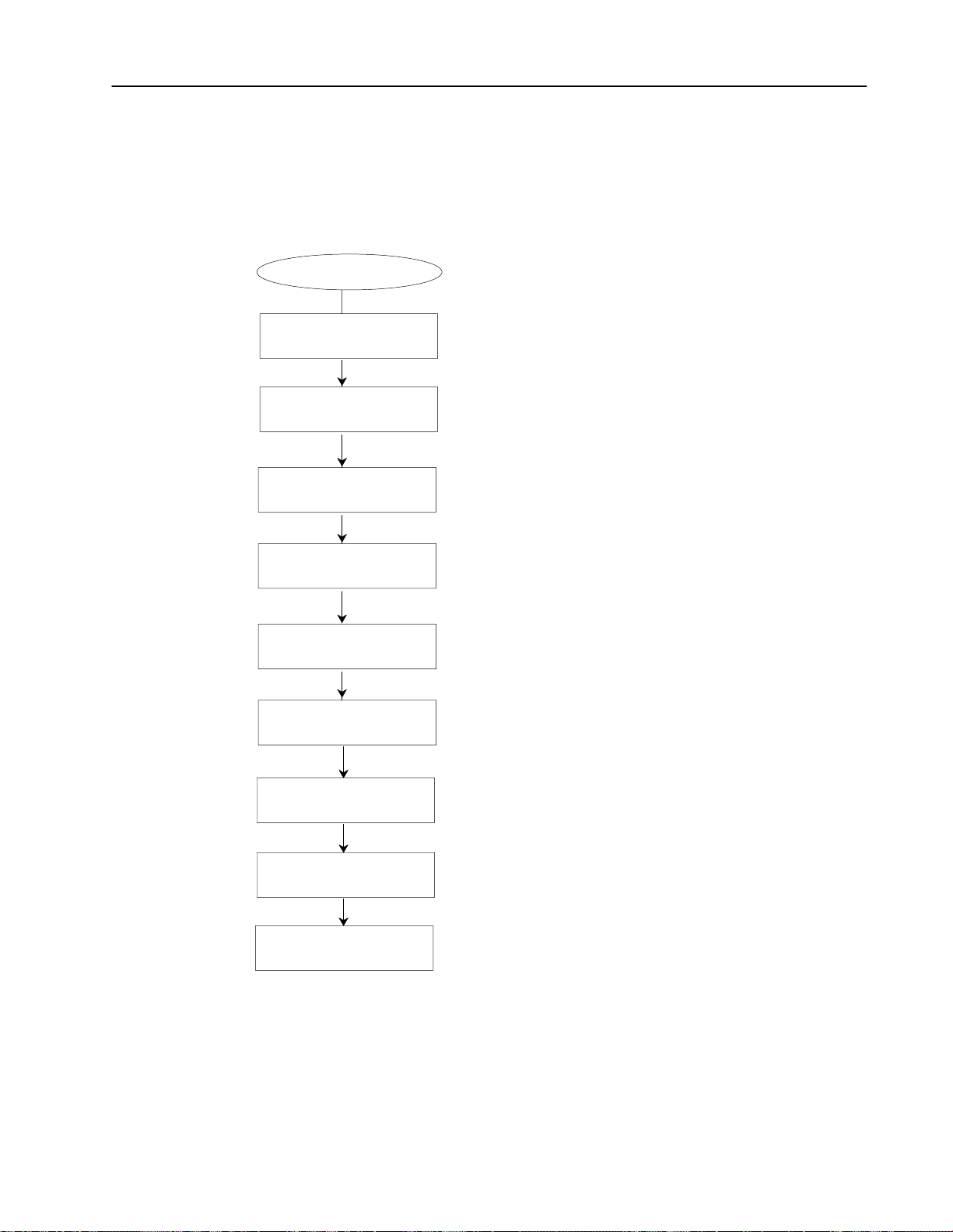
7–7Using ODS Communication Configuration
Configuring the 1784-KTK1
To configure the information for the 1784-KTK1 module, select (A)
from the Driver Type menu. Figure 7.6 describes the menu flow
used to configure the KTK1 module.
Figure 7.6
Configuration Flow for the 1784KTK1
1784KT Driver Type
Port Type Desired
Address of Driver Card
DH+ Station Address of Terminal
DH+ Station Address
of Logic Controller
Select the communications port that will be used for Data Highway Plus
1.
communications.
Select the address of the driver card that will communicate over the
2.
Data Highway Plus (PLC). This address must match the address selected
on the switch setting on the 1784KT module. Address range is 10 binary
digits. Default value is 00001 10000.
3.
Select the station address of the ODS terminal on the Data Highway Plus.
Address range is from 0 to 77 (octal). The default value is 77.
Select the station address of the logic controller on the Data Highway Plus.
4.
Address range is from 0 to 77 (octal). The default is 02.
Connection Type Desired
Device Interrupt
IMC12x Rack Address
IMC12x Group Address
Handshake Delay
Select the type of connection used on the Data Highway Plus. Direct
5.
indicates only a logc controller and the ODS terminal are connected.
Multidrop indicates more than one logic controller and ODS terminal are
connected. The default selection is Direct.
Select the device interrupt address of the 1784KTK1 module (IRQ3, IRQ5,
6.
IRQ10, IRQ12). Chose an address that does not conflict with an already
installed card. The default selection is IRQ5.
Select the IMC rack address. The address range is 0 through 7.
7.
The default value is 0. IMC 12x includes IMC-120, IMC-121,
IMC-123, and IMC-123CR.
Select the IMC group address. The address range is 0 through 7.
8.
The default value is 0. IMC 12x includes IMC-120, IMC-121,
IMC-123, and IMC-123CR.
9.
Select the delay time between Block Transfer read/write requests and Block
Transfer read requests to get the status from the last BLT. The delay time
range is 0 to 9999 milliseconds. The default value is 2500.
Publication MCD-5.1 -August 1999
Page 82

7–8 Using ODS Communication Configuration
KTK1 Address Considerations
Memory
Address
(Hexadecimal)
A000:0000
A400:0000
A800:0000
AC00:0000
B400:0000
B800:0000
C000:0000
C400:0000
C800:0000
CC00:0000
D000:0000
D400:0000
D800:0000
A14 A19A18A17A16A15
OFF
ON
OFF
ON
ON
OFF
OFF
ON
OFF
ON
OFF
ON
OFF
OFF
OFF
ON
ON
OFF
ON
OFF
OFF
ON
ON
OFF
OFF
ON
Where:
OFF
OFF
OFF
OFF
ON
ON
OFF
OFF
OFF
OFF
ON
ON
ON
Figure 7.7 lists the valid KTK1 addresses.
Figure 7.7
Valid KTK1 Address
Network Board Switch Settings
A20
ON
ON
ON
ON
ON
ON
OFF
OFF
OFF
OFF
OFF
OFF
OFF
OFF
OFF
OFF
OFF
OFF
OFF
ON
ON
ON
ON
ON
ON
ON
1 = Factoryset address
2 = Preferred addresses when readdressing the 1784KT K1 board
3 = KTK1 board in a COMPAQ 386 that uses a VGA card
4 = KTK1 board in a computer that uses an EGA card
ON
ON
ON
ON
ON
ON
ON
ON
ON
ON
ON
ON
ON
OFF
OFF
OFF
OFF
OFF
OFF
ON
ON
ON
ON
ON
ON
ON
A21
OFF
OFF
OFF
OFF
OFF
OFF
ON
ON
ON
ON
ON
ON
ON
A22
OFF
OFF
OFF
OFF
OFF
OFF
ON
ON
ON
ON
ON
ON
ON
A23
OFF
OFF
OFF
OFF
OFF
OFF
ON
ON
ON
ON
ON
ON
ON
Software
Address
(Binary)
0001010000
1001010000
0101010000
1101010000
1011010000
0111010000
0000110000
1000110000
0100110000
1100110000
0010110000
1010110000
0110110000
6122 Considerations
IBM PC XT Considerations
If you use a 6122 as your programming terminal, set the KTK1
address to 101001100001. Also, change the switch setting on the
KTK1 module to reflect the address. See the 1784-KTK1 Product
Data, publication 1784-2.3, for instructions about setting switches.
If you use an IBM PC XT as your programming terminal, you can
use only IRQ3. You cannot use IRQ5 because the hard drive already
uses IRQ5. The IBM PC XT cannot use IRQ10 and IRQ12
interrupts.
Publication MCD-5.1 -August 1999
Page 83

7–9Using ODS Communication Configuration
Configuring a Serial Driver
Serial Driver Type
Port Type Desired
DH+ Station Address of Terminal
You can use a serial port (COM1 or COM2) that is connected to the
terminal and you can use the serial port with one of these
communication modules:
• 1770-KF2
• Series B Communication Interface Module
• 1785-KE Communication Interface Module (resides in 1770 I/O
rack)
To configure the information for the Serial Driver module, select (D)
from the Driver Type menu. Figure 7.8 describes the menu flow
used to configure the serial port.
Figure 7.8
Configuration Flow for the Serial Driver Type
Select the communications port that will be used for Data Highway Plus
1.
communications.
2.
Select the station address of the ODS terminal on the Data Highway Plus.
Address range is from 0 to 77 (octal). The default value is 77.
DH+ Station Address
of Logic Controller
Baud Rate of Driver
Parity
Duplex
Error Checking Mode
IMC12x Rack Address
IMC12x Group Address
Handshake Delay
3.
Select the station address of the logic controller on the Data Highway Plus.
Address range is from 0 to 77 (octal). The default is 02.
Select the baud rate using the Data Highway Plus communications. The
4.
default value is 2400 baud.
5.
Select the parity mode. None, Even, or Odd when using serial to Data
Highway Plus. The default selection is None.
6.
Select the duplex mode. Half or Full, when using the serial to Data
Highway Plus. The default selection is Full.
7.
Select the Error Checking mode. CRC or BCC when using serial to Data
Highway Plus. The default selection is BCC.
8.
Select the IMC rack address. The address range is 0 through 7.
The default value is 0. IMC 12x includes IMC-120, IMC-121,
IMC-123, and IMC-123CR.
Select the IMC group address. The address range is 0 through 7.
9.
The default value is 0. IMC 12x includes IMC-120, IMC-121,
IMC-123, and IMC-123CR.
10.
Select the delay time between Block Transfer read/write requests and Block
Transfer read requests to get the status from the last BLT. The delay time
range is 0 to 9999 milliseconds. The default value is 2500.
Publication MCD-5.1 -August 1999
Page 84

7–10 Using ODS Communication Configuration
Using INTERCHANGE
INTERCHANGE Driver Type
DH+ Station Address of
Logic Controller
Network Access
Bridge Address
9/Series Rack Address
To configure the information for INTERCHANGE, select (E) from
the Driver Type menu. Figure 7.9 describes the menu flow used to
configure INTERCHANGE.
Figure 7.9
Configuration Flow for Using INTERCHANGE (CNCs only)
1.
Select the station address of the logic controller on the Data Highway Plus.
Address range is from 0 to 77 (octal). The default value is 02.
2.
Select the network access, Local or Remote, when using the 1784KT
module. The default selection is Local.
Select the local or remote bridge address. The address range is
3.
0 through 376 (octal). The default value is 110.
4.
Select the 9/Series Rack Address. Although the range is stated to be
between 0 and 377 octal, you need to set this number to be the same
value as the AMP parameter Adapter Rack Number. This AMP parameter
can have a value between 0 and 59 decimal, so the setting for the rack
address cannot exceed 73 octal. The default value is 3. Refer to your
AMP manual for more information.
Select the 9/Series group address. The address range is 0 through 7.
9/Series Group Address The default value is 0. 9/Series includes 9/230, 9/240, 9/260,
5.
9/290, and 9/440.
Select the delay time between Block Transfer read/write requests and Block
6.
Handshake Delay
Transfer read requests to get the status from the last BLT. The delay time
range is 0 to 9999 milliseconds. The default value for 9/230 and 9/440 is
200 ms. For the 9/260 and 9/290 the default is 100 ms.
Used to choose the driver configuration in the INTERCHANGE configuration file.
7.
INTERCHANGE Pushwheel Number
The driver confiuration in the INTERCHANGE configuration file, this chooses other DH+
settings such as hardware board, board address, etc. Default: 1, Range: 18.
Publication MCD-5.1 -August 1999
Page 85

7–11Using ODS Communication Configuration
Configuring DH+ Under
Windows NT In ODS
Use the following instructions to configure DH+ under Windows NT
via ODS:
1. In your Windows NT application, launch ODS in a DOS shell.
With RSLinx running, follow steps 1 through 4 as described in
Creating a Project (refer to Chapter 5).
2. Select
DH+ Network as your application type by choosing <D>.
3. When the system prompts you for your desired driver type,
RSLinx is selected by default. Choose
<F> to continue to the next
screen.
4. A list box containing DH+ drivers that are currently configured in
RSLinx appears. Select the name corresponding to your
configured driver.
Publication MCD-5.1 -August 1999
Page 86

7–12 Using ODS Communication Configuration
Configuring RSLinx for Ethernet
RSLinx for Ethernet
AB_ETH
Driver Number
RSLinx Station Address
of 9/Series
Downloading AMP Files for Use with the 9/PC
Refer to Figure 7.10 to see the menu flow used to configure RSLinx
for Ethernet.
Figure 7.10
Configuration Flow for Using RSLinx for Ethernet (CNCs only)
1.
Select the appropriate driver number for your configuration
This number corresponds to the AB_ETH driver configured in
RSLinx for Ethernet communication. The driver range is 01 to
64 (decimal). The default value is 01.
2.
Select the station address that was mapped to the 9/Series control's
IP address during RSLinx configuration. The address range is 0 to
63 (decimal). The default value is 0.
After you edit and save your AMP file, download it to the 9/PC so
that it is the currently active AMP file. You can use ODS to
download AMP files three ways:
• from the local host PC into the 9/PC (refer to page 5–4)
• from a separate network–connected ODS workstation that is
running Windows NT to the host PC and into the 9/PC card
• from an ODS workstation running Microsoft Windows NT and
Dial–up Networking, connected to the serial port of the host PC
running Microsoft’s’ Remote Access Services (RAS), and into the
9/PC card
In all cases, the information you enter when creating the project is
used to direct the download to the correct 9/PC for this project. This
includes the host PC name and the topic name of the 9/PC card. This
project information can be changed at any time.
Publication MCD-5.1 -August 1999
Page 87

7–13Using ODS Communication Configuration
Downloading an AMP File from the Host PC to a 9/PC
When you download locally to the 9/PC, no external connections are
required. The download is done across the computer’s PCI buss.
This procedure loads the selected AMP file into the memory of the
9/PC card, then force the 9/PC restart. This restart will either be
manually or automatically, depending on how you configured your
9/PC settings during installation.
1. Select the Download option from the F3–Application menu.
2. Select the Send AMP params option from the F4–Utility menu.
The following message displays:
Please place the control in ESTOP to download
After you press any key, the workstation displays the list of AMP
files for this project.
3. Select or type in an AMP file name. The workstation displays the
message:
Waiting for response on the control
This message in only displayed while ODS is waiting for the
9/PC to verify that it is in E–Stop. The displaying of the message
is often too brief to even be seen under normal operation.
The workstation then displays the message:
Download in progress
Percent transferred xx %
ODS displays the percentage of the file that was already
transferred.
When the download process is complete, ODS displays the
message:
DOWNLOAD COMPLETE
Publication MCD-5.1 -August 1999
Page 88

7–14 Using ODS Communication Configuration
4. After downloading any new AMP file, you must restart the 9/PC.
Depending on how your 9/PC Support Service is configured, this
restart can be initiated in one of two ways:
• If you selected the AutoStart After AMP Download option,
the 9/PC will restart as soon as the download completes.
• If you did not configure your 9/PC to automatically start after
an AMP download, follow the procedure discussed in the
9/PC Installation and Integration Manual to restart the 9/PC.
In either case, the 9/PC operator interface or Basic Display Set
(BDS) displays the message:
CNC was stopped. Restart the CNC using the 9/PC
configuration manager. Select “exit” or use the
options menu to reconnect BDS to the CNC.
This indicates that BDS must be “reconnected” to the 9/PC card,
as indicated in the message. Attempting to reconnect the BDS
without restarting the 9/PC will results in the error message:
Cannot Link to ABOCISERVER | CNC_1
Once you restart the 9/PC, the new AMP parameter values
become available for system operation.
Downloading Over a Network from a Second PC
ODS can download AMP files to the 9/PC over a communications
network assuming: a) both the ODS workstation and the host PC
are on the network and b) the computer running ODS and initiating
the download is running Windows NT.
When an AMP file is downloaded to the 9/PC, the ODS workstation
downloads the file directly to the 9/PC card. This means that the
previous AMP file is no longer in use and unless this older file was
backed up, it no longer exists.
The difference between a network download and a local/host
download is in the Computer Name that you entered under the
project information. In case of network download, you must enter
the name of the host computer.
To determine the name of the host computer, perform these steps at
the host computer:
Publication MCD-5.1 -August 1999
A. Click the Windows NT Start button and select Settings.
B. Click on Control Panel to activate the Network control.
C. Select the Identification tab to identify the computer name.
If this information is correct, follow the steps in the previous section
on downloading an AMP file.
Page 89

7–15Using ODS Communication Configuration
Downloading from the Serial Port of a Second PC
ODS can use the serial ports of your workstation and the host
computer to download an AMP file.
Important: These computer configurations are required for correct
operation of this capability :
• The computer running ODS and initiating the download must
also be running Windows NT
• The 9/PC host computer must have Remote Access Services
(RAS) installed and configured. RAS allows the host
computer to act as a server to the ODS (or client) PC
• Both PCs must have Dial–up Networking installed. Dial–up
Networking is required in a Windows NT system to enable
remote communicatations via a modem or serial cable
• Both PCs must have identical user accounts created to
facilitate dial–up networking operation
When an AMP file is downloaded to the 9/PC, the ODS workstation
downloads the file directly to the 9/PC card. This means that the
previous AMP file is no longer in use and if this older file was not
backed up, it no longer exists.
The difference between a download from a serial connection from a
second PC and a local/host download is in the Computer Name that
you entered under the project information. In case of a serial
download, you must enter the name of the host computer.
Setting up the computers needs to be done only one time. The
following steps are necessary to correctly install and configure the
communications software on the two PCs. Note that an
installation/setup must be completed for both the ODS workstation
and the host computer.
Setting Up the 9/PC Host (or Server) Computer
1. Double–click the My Computer icon on your PC’s desktop.
2. Double–click Dial–Up Networking.
3. Click Install to connect your computer to your remote network.
4. Enter the path where your files are located
(e.g., yourdiskdrive:\I386) in the Copy files from: text box. The
drive should appear by default, but if it doesn’t, enter your CD
ROM drive that contains the Windows NT CD.
• If the message No RAS Capable Devices Available appears,
click YES next to modem configuration
• Select Don’t Detect, Select From List. When the list box
appears, select Standard Modem and Dial–Up Serial Cable
Between 2 PCs
Publication MCD-5.1 -August 1999
Page 90

7–16 Using ODS Communication Configuration
5. Click OK to add COM1 – Dial–Up Networking Serial Cable
Between 2 PCs. The Remote Access Setup window appears.
6. Select the Configure button in the Remote Access Setup
window.
7. Select Dial out and Receive calls, to allow the host computer to
be both the RAS Client and Server.
8. Click OK
9. On the remote Access Setup click Network...
Publication MCD-5.1 -August 1999
Page 91

7–17Using ODS Communication Configuration
10.Select the following Dial out Protocols: NetBEUI and TCP/IP.
Select the encryption setting Require encrypted authentication.
This setting is required.
Click the Configure button next to NetBEUI.
11.Select Entire Network in the RAS Server NetBEUI
Configuration box. Click OK.
You can use TCP/IP, but you must either assign a pool of static IP
addresses to be available for the clients, or if you have a DHCP
server, allow it to assign client IP addresses.
Publication MCD-5.1 -August 1999
Page 92

7–18 Using ODS Communication Configuration
12.Click on the Configure button next to TCP/IP to get RAS Server
TCP/IP configuration dialog.
13.Check the Entire Network button. If you are setting up the ODS
(client) computer, go to step 2 of the next section. If you are
setting up the 9/PC host (server) computer, go to the next step.
14.Check the Use static address pool button if you are assigning
static addresses. If you are using DHCP, click the Use DHCP
button and skip the next step.
15.Enter your starting IP address in the Begin box, and your ending
IP address in the End box.
16.Click OK. Click Continue to install RAS.
17.Click Close. When prompterd, reboot the computer.
These next steps assume that you set up accounts on the subject PC
for those users (or administrators) who will dial in to the server PC:
18.After logging into Windows NT,
A. Click the Windows NT Start button and select Programs.
B. Select Administrative Tools (Common).
C. Select Remote Access Admin.
Publication MCD-5.1 -August 1999
19.Select Users → Permissions.
20.Click on the Users name (or administrator) who you want to
permit to dial in to the server. Check the Grant dialin
permission to user checkbox.
Page 93

21.Under Call Back, select No Call Back, then click OK.
22.Select: Server → Start Remote Access Server.
In the Server field, the name of the local computer should already
be present. If not, enter the computer name preceded by two back
slashes (e.g., \\yourcomputername). Click OK to start the
service.
Setting Up the ODS (or Client) Computer
1. Repeat steps 1. through 13. from the previous section.
2. Relog in. Double click the My Computer icon.
3. Double click Dial–up Networking.
• If you did not previously configure any dial–up Phonebook,
the New Entry Wizard appears.
• Click Next, and select Plain Text Password
• Select enter (or Next) through the rest of the selections until
the following screen appears:
4. Click More and Select Edit Entry and Modem Properties.
7–19Using ODS Communication Configuration
Publication MCD-5.1 -August 1999
Page 94
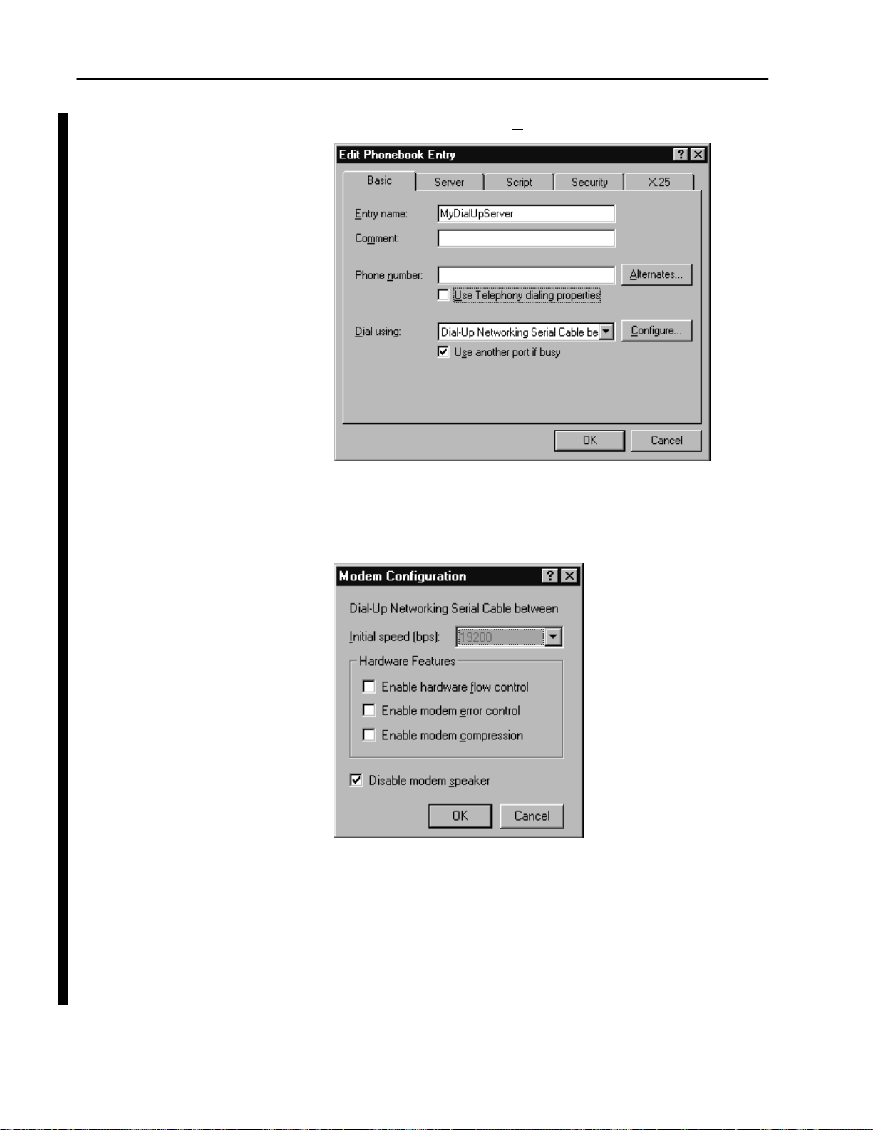
7–20 Using ODS Communication Configuration
5. Click Configure next to Dial using:.
6. Select a baud rate that is available on this and the server PC.
7. Click OK on this and the Edit Phonebook Entry windows.
8. Disconnect your EtherNet cable.
9. Start the RAS server on the 9/PC Host (server PC) if you did not
already do so in the last section:
Publication MCD-5.1 -August 1999
A. Click the Windows NT Start button and select Settings.
B. Select Control Panel.
Page 95

7–21Using ODS Communication Configuration
C. Double click the Services control panel to view the available
services.
D. Locate and highlight the Remote Access Server. Click
Start.
10.Click Dial to connect to the 9/PC host (server PC) from your
ODS workstation (client PC).
Troubleshooting Tips for RAS Configuration
If you receive the message “Error 651” when establishing a
connection, the first items to check are:
• cable pinouts are correct and have continuity
• Cable connections are good to the PC serial ports
• The port you have connected the cable to actually corresponds to
the port name you have configured (e.g.,COM1 vs COM2).
• Baud rates and other port settings for the configured ports must
be the same on the client and Server PCs
• Baud rates up to 115,200 have been successfully used on short
cable lengths.
What to Do Next
If you have any further questions after reading this manual, contact
Allen-Bradley Software Support Services at (440) 646-6800.
END OF CHAPTER
Publication MCD-5.1 -August 1999
Page 96

Index
Symbols
[CTRL-C], 2-3
[ESC] key, 3-6
using the, 3-12
[PgDn], 3-6
[PgUp], 3-6
Numbers
1770KF2, 7-9
1771 I/O rack, 7-9
1784KL, configuring, 7-3
1784KT, configuring, 7-3
1784KTK1, configuring, 7-7
1785KE Communication Interface Module, 7-9
6122 considerations, 7-8
8100 HS110, software, 2-6
A
About option, 3-5, 6-1
AMP, application, 3-10, 5-21
Application
AMP, 5-21
Download, 5-21
files, 3-10
I/O assignments, 5-21
menu, 3-10
MML, 5-21
organization, 3-10
PAL, 5-21
Part programs, 5-21
selecting, 5-21
Upload, 5-21
Arrow keys, 6-10
down, 3-5
up, 3-5
AUTOEXEC.BAT file
modifying, 2-7
where to find, 2-1
B
Backup copy, 2-1
Backup option, 5-17, 5-19
Backup project, 5-18
Bad command or filename, 2-4, 3-1, 3-2
Beeper, On/Off, 4-4
Buffers, 2-6
C
Cancel
operation, 3-12
print request, 6-9
CNC, 1-1
COM1 serial port, 7-9
COM2 serial port, 7-9
COMMAND.COM file, 2-1
Communication Mode, 7-2
6122 considerations, 7-8
Configuring 1784KL, 7-3
Configuring 1784KT, 7-3
Configuring 1784KTK1, 7-7
Configuring DH+, 7-11
configuring RSLinx, 7-12
Configuring Serial Driver, 7-9
IBM PC/XT considerations, 7-8
KTK1 address considerations, 7-8
Menu Structure, 7-3
Programming Data Highway Plus, 7-6
Using INTERCHANGE, 7-10
Compatibility, computer, 1-3
computer name, 7-14
Computers Compatible with ODS, 1-3
CONFIG.SYS file, modifying, 2-6
Configuration Flow
1784KL, 7-4
1784KT, 7-4
1784KTK1, 7-7
Serial Driver Type, 7-9
Configuring
1784KL, 7-3
1784KT, 7-3
1784KTK1, 7-7
Page 97

I–2
Index
DH+ Under Windows NT (TM), 7-11
INTERCHANGE, 7-10
RSLinx for Ethernet, 7-12
serial driver, 7-9
1770KF2, 7-9
1771 I/O rack, 7-9
1785KE Communication Interface Module, 7-9
Series B Communication Interface Module, 7-9
Control family, 7-2
9/PC, 5-4
9/Series, 5-3
select, 5-2
Copy
files
from a current project, 6-2
from another project, 6-5
project, 5-12
project FROM, 5-12
project TO, 5-13
D
Data Highway Plus, programming, 7-6
Delete
file, from a current project, 6-4
project, 5-16, 5-19
Delete option, 6-4
Device names, 3-3
DEVICE=DF1DRV.SYS, 2-6
DH+ network, configuring to, 5-9
Dial-Up Networking Wizard, 7-15, 7-19
Directories
selecting from, 3-11
using, 3-10
Directory, file, 3-10
Display, ODS file, 6-10
download
RAS software, 7-15
Serial port, 7-15
Drive Type menu, 7-3
E
EDLIN.COM file, 4-2
Entering
files, 3-11
project names, 3-11
Error Messages, interpreting, 3-12
Exiting, ODS software, 3-12
F
F1File menu, 3-5
exit to DOS, 3-12
F2Project menu, 3-9, 5-1
F3Application menu, 3-4, 3-10
F4Utility menu, 3-10
File
copy
from a current project, 6-2
from another project, 6-5
delete, from a current project, 6-4
display, 6-10
print, 6-8
READ.ME, 2-5
rename, from a current project, 6-3
type, choosing, 6-2
File directory, 3-10
Files
entering, 3-11
machine configuration, 1-1
machine interface, 1-1
machine motion control, 1-1
Documentor, using, 6-8
DOS
DISKCOPY command, 2-1
executing from ODS, 4-6
returning to, 3-12
Download
AMP files, for 9/PC, 7-12
application, 5-21
local host PC, 7-13
network , 7-14
H
Hardware Requirements, 1-3
Help, online, 3-5
I
I/O assignments, application, 5-21
IBM PC/XT considerations, 7-8
Page 98

Index
I–3
IMC.BAT file, 3-3
Information option, 5-8
INTERCHANGE, configuring, 7-10
INERCHANGE Configuration Flow, Serial Driver Type,
7-10
K
Keyboard
setup, 4-2
type, 4-2
KT addresses, valid, 7-5
KTK1 addresses
considerations, 7-8
valid, 7-8
M
Machine
configuration files, 1-1
interface files, 1-1
motion control files, 1-1
Menu bar, 3-4
AMP editor utility, 3-4
toplevel, 3-4
Menu choices
ghosted, 3-4
highlighted, 3-4
Menu options, selecting, 3-5
Menu structure, 7-3
Menus, pulldown, using, 3-4, 3-5
MML, application, 5-21
MODE BW80, 3-3
Modifying, file
AUTOEXEC.BAT, 2-7
CONFIG.SYS, 2-6
MS-DOS, 1-3
N
New option, 5-2
O
ODS Software, hardware requirements, 1-3
ODS software
backup copy, 2-1
directory characteristics, 3-11
exiting, 3-12
getting started with, 3-1
installing, 2-1
main features, 1-2
memory requirement, 2-2
package content, 1-3
screen
first line, 3-4
second line, 3-4
starting, 2-7
typical process, 1-2
welcome screen, 3-1, 3-2
Online help, using, 3-5
P
PAL, application, 5-21
Part programs, application, 5-21
PATH command, 2-1, 2-4
Print
cancel request, 6-9
Documentor, 6-8
ODS file, 6-8
Print Device, Configuring Your Windows NT, 4-4
Print option, 6-8
Programming, Data Highway Plus, 7-6
Project, 5-1
active, 5-7
comparison to file storage, 3-8
copy FROM, 5-12
copy TO, 5-13
copying a, 5-12
creating a, 5-1
delete, 5-16, 5-19
directory, 3-9
information
changing, 5-9
displaying, 5-8
menu, 3-9
names, entering, 3-11
opening an existing, 5-7
organization, 3-9
rename, 5-15
rename FROM, 5-15
rename TO, 5-15
restore, 5-19
subdirectories, 5-4
Page 99

I–4
Index
R
RAS, 7-15
RAS Configuration, troubleshooting, 7-21
READ.ME file, 2-5
Remote Access Services, 7-15
Rename
file, from a current project, 6-3
project, 5-15
project FROM, 5-15
project TO, 5-15
Rename option, 6-3
Restore, project, 5-19
RSLinx, configuring for Ethernet, 7-12
RSLinx Configuration Flow, Serial Driver Type, 7-12
S
Second PC, network download, 7-14
Selecting
application, 5-21
Communication Mode, 7-2
control family, 5-2
menu option, 3-5
utility, 5-22
Serial Communication , Configuring, 4-3
Serial driver, configuring, 7-9
Series B Communication Interface Module, 7-9
Startup
using DOS, 3-2
using Windows, 3-1
Status Line, 3-4
active project, 5-7
Application, 3-4, 3-7, 3-9
Project, 3-4, 3-7, 3-8
reading, 3-7
Utility, 3-4, 3-7
T
Text editor
EDLIN.COM file, 4-2
setup option, selecting, 4-1
using, 4-1
Troubleshooting, RAS Configuration, 7-21
Type option, 6-10
U
Upload, application, 5-21
User project warning, 2-9
Utility
functions, 3-10
menu, 3-10
selecting, 5-22
V
Verify, On/Off, 4-5
W
Welcome screen, 3-1, 3-2
Windows NT, configuring DH+ using, 7-11
Windows NT (TM), configuring for DH+, 7-11
Page 100

I–2
Index
AllenBradley, a Rockwell Automation Business, has been helping its customers improve
productivity and quality for more than 90 years. We design, manufacture and support a broad
range of automation products worldwide. They include logic processors, power and motion
control devices, operator interfaces, sensors and a variety of software. Rockwell is one of the
world's leading technology companies.
Worldwide representation.
Argentina • Australia • Austria • Bahrain • Belgium • Brazil • Bulgaria • Canada • Chile • China, PRC • Colombia • Costa Rica • Croatia • Cyprus • Czech Republic •
Denmark • Ecuador • Egypt • El Salvador • Finland • France • Germany • Greece • Guatemala • Honduras • Hong Kong • Hungary • Iceland • India • Indonesia •
Ireland • Israel • Italy • Jamaica • Japan • Jordan • Korea • Kuwait • Lebanon • Malaysia • Mexico • Netherlands •New Zealand • Norway • Pakistan • Peru •
Philippines • Poland • Portugal • Puerto Rico • Qatar • Romania • Russia-CIS • Saudi Arabia • Singapore • Slovakia • Slovenia • South Africa, Republic • Spain •
Sweden • Switzerland • Taiwan • Thailand • Turkey • United Arab Emirates • United Kingdom • United States • Uruguay • Venezuela • Yugoslavia
AllenBradley Headquarters, 1201 South Second Street, Milwaukee, WI 53204 USA, Tel: (1) 414 3822000 Fax: (1) 414 3824444
Publication MCD-5.1 -August 1999 PN 176716
Copyright 1999 AllenBradley Company, Inc. Printed in USA
 Loading...