

Page 1
Installation Instructions
PHOTOSWITCH
IMPORTANT: SAVE THESE INSTRUCTIONS FOR FUTURE USE.
Bulletin 45AST Area Array
Description
The Allen-Bradley 45AST Area Array is a compact, easy-touse nonsafety light screen for small part detection and
assembly applications. This transmitted beam array is ideal for
use in a variety of applications from counting to process
initiation.
The 45AST introduces “Two-Dimensional Array Scanning
Technology” which allows the user to sense an object as it
passes through the pair of arrays regardless of orientation
provided that one axial dimension meets the minimum
resolution requirements.
Features/Benefits
S Two dimensional array scanning technology
S Minimum object resolution (from 1117 mm
(0.430.66in.)
S Sensing ranges up to 2.5 m (8.2 ft)
S Highly visible alignment LEDs
S Easy bracket-free mounting
S IP67 rated enclosure
Sensor Alignment
1. Visually align the emitter and receiver units until the
orange output LED turns ON.
2. To ensure that the beam is centered, it is recommended to
sweep the emitter or receiver in the horizontal and vertical
plane and determine at what position the output indicator
turns ON and then turns OFF. Set the sensor midway
between both positions.
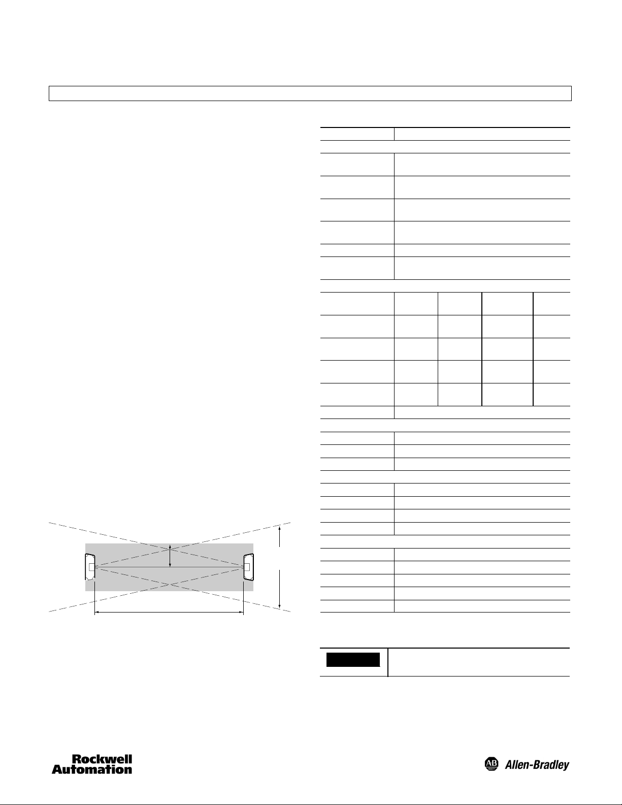
Interference Protection
To minimize interference and false triggering from highly
reflective objects, keep object within a minimum distance of
100 mm (4in.), parallel to the effective beam center line.
100 mm
Zone
150 mm
Maximum
Spread
Maximum
Range
Specifications
Certifications cULus and CE marked for all applicable directives
Environmental
Operating
Environment
Operating
Temperature [C (F)]
Vibration 1055Hz, 1 mm amplitude; meets or exceeds IEC
Shock 30 g with 11 ms pulse duration, meets or exceeds IEC
Relative Humidity 3585%
Ambient Light
Immunity
Optical [mm (in.)]
Models
45AST--1JB1--4
45AST--1JB2--4
45AST--1JB3--4
45AST--1JB4--4
Light Source Infrared (860 nm)
Electrical
Voltage 1224V DC
Current Consumption Emitter (80 mA max.), Receiver (110 mA max.)
Sensor Protection Short circuit, reverse polarity
Outputs
Response Time 8msmax.
Output Type PNP or NPN
Output Mode Light operate
Output Current 100 mA @ 24V DC
Mechanical
Housing Material Aluminum
Lens Material Acrylic
Connection Types 4-pin DC micro (M12) pigtail
Supplied Accessories None
Connector Material Mounting brackets, cordsets
Insert N for NPN models or P for PNP models.
Range shown in m (ft)
Values shown in mm (in.)
IP67
-- 5 +55 (23131)
60947--5--2
60947--5--2
5000 lux (incandescent light)
Sensing
Range
0.52
(1.66.5)
0.150.8
(0.52.6)
0.52.5
(1.68.2)
0.150.8
(0.52.6)
Height
50 (1.9) 15 (0.59) 5
100 (3.9) 11 (0 .43 ) 10
100 (3.9) 13 (0.51) 10
150 (5.9) 17 (0.66) 10
Resolution
Optical
Axis
IMPORTANT
Avoid installation near high frequency
fluorescent lights and inverters.
Page 2
Mounting the Sensor
Maintenance
ATTENTION
To avoid intermittent operation, do not
mount the sensors to surfaces that may
shift or be exposed to excessive vibration.
ATT E N T ION
When cleaning the face of the sensor, do
not use aggressive or abrasive materials
which could reduce the operating range
and accuracy.
Securely mount the sensor on a firm, stable surface or
Use a dry, soft cloth for cleaning the lens area.
support. Once securely mounted, the sensor may be wired as
indicated in the wiring diagrams.
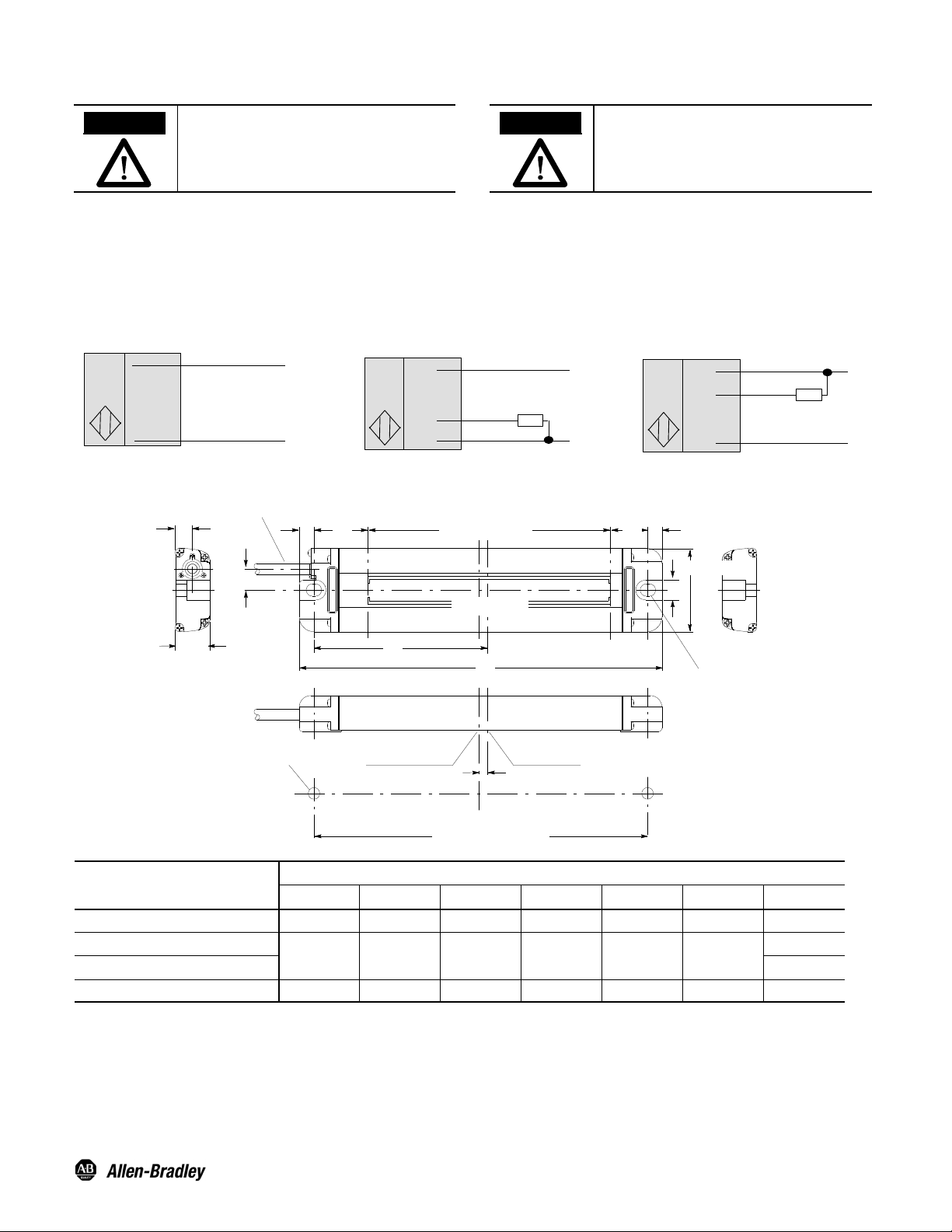
Wiring Diagrams
Quick disconnect connection is shown in the following diagrams. Pin numbers correspond to male connectors on the sensor.
Emitter
Cable
Brown (1)
Blue (3)
Cable
+
--
Brown (1)
Black (4)
Blue (3)
+
+--
Load
--
NPN OutputPNP Output
Cable
Brown (1)
White (2)
Blue (3)
Load
+--
Approximate Dimensions [mm in.]
7.2
(0.28)
Cable Dia. 4 (0.16)
PVC: 3 m (9.8 ft)
14.5
(0.57)
9.0
(0.35)
6.5
(0.25)
8.2
(0.32)
6.5
(0.25)
34 (1.33)
Dia. 116.8 (4.6) x 2
B (Detecting Width)C B
Detecting Width
E
A
+
--
Model
45AST--1JB1--4
45AST--1JB2--4
45AST--1JB3--4
45AST--1JB4--4
N = NPN and P = PNP.
2--M4
A B C D E F G
100 (3.93) 50 (1.96) 22.5 (0.88) 14.5 (0.57) 47.5 (1.87) 4(0.15) 87 (3.42)
150 (5.9) 100 (3.93) 22 (0.86) 15 (0.59) 72 (2.83) 3.5 (0.13)
200 (7.87) 150 (5.9) 22 (0.86) 15 (0.59) 97 (3.81) 3.5 (0.13) 187 (7.36)
PHOTOSWITCHR is a registered trademark ofRockwell
Automation.
Center of Installation
Hole Pitch
Center of Axis
F
G (Installation Hole Pitch)
2
[mm (in.)]
Publication 10000106491 Ver 01
PrintedinUSA
137 (5.39)
137 (5.39)
January 2012
 Loading...