

Page 1
Installation Instructions
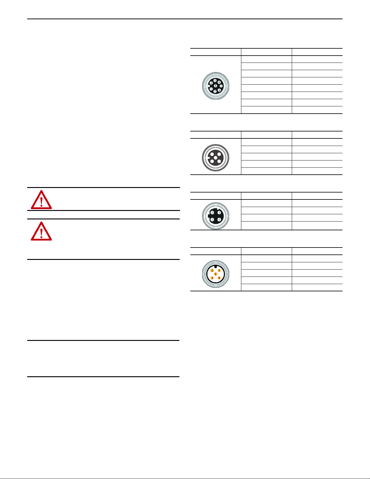
M12 8-pin
Female
M12 5-pin
Female
M12 5-pin
Male
M12 4-Pin
Female D-Code
(Network)
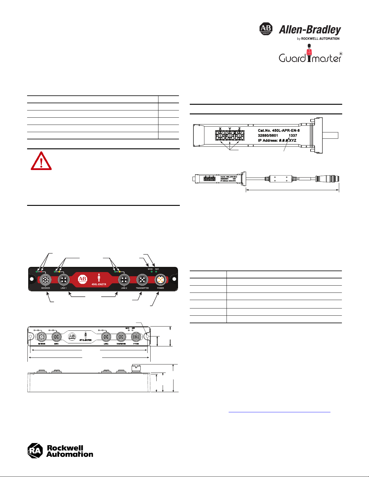
Network Indicator
Module Indicator
Link Indicators
Receiver Indicators
Front View
Side View
27.23
(1.07)
37.91
(1.49)
23.1
(0.91)
26.1
(1.03)
160.5 (6.32)
168.61 (6.63)
13.615
(0.535)
M3 (#8)
Dimensions in mm (in.)
Dimensions in mm (in.)
IP Address Switches
Mfg Datecode YYWW
Original Instructions
GuardShield Safety Light Curtain EtherNet/IP Network Interface
Catalog Number 450L-ENETR
Top ic Pa ge
Product Overview and Dimensions 1
Install the Network Interface 1
Reset to Factory Default and Protection Mode 2
Status Indicators 3
Specifications 3
ATTENTION: You must familiarize yourself with installation
and wiring instructions and requirements of all applicable
codes, laws, and standards. In accordance with applicable
codes of practice, suitably trained personnel are required to
install, adjust, put into service, use, assemble, disassemble,
and/or maintain this equipment. If this equipment is used in
a manner that is not specified by the manufacturer, the
protection that is provided by the equipment can be
impaired.
Module is designed to meet IEC 61496.
450L-APR-EN-8 Plug-in Module
IMPORTANT
The plug-in module is purchased separately.
205 (8)
Product Overview and Dimensions
450L-ENETR Network Interface
Install the Network Interface
This section contains installation-related information.
Assign IP Address
The 450L-ENETR network interface must be assigned a fixed (static) IP address to
maintain continued communication with the network. The IP address is set on the
450L-APR-EN-8 plug-in module.
Valu e Des cripti on
000 Clear explicit protected mode
001…254 Private address (#.#.#.XYZ)
888 Factory reset
900
999 DHCP
All others Do not use
(1) When explicit protection mode is set, explicit messages that affect the operation of the device are
blocked. Examples of blocked messages are changes to the IP address, reset of the module, and
update of the firmware. Explicit messages can still fetch diagnostic information.
Set explicit protected mode
There are four ways of assigning a fixed IP address:
• Use the XYZ rotary switches to set a 'Private' IP address.
• Use the Rockwell Automation BootP/DHCP tool, version 2.3 or later,
which ships with Studio 5000® software (RSLogix 5000® software).
• Use RSLinx® software.
• Have your network administrator configure the ENETR network
interface via the network DHCP server.
If the 450L-ENETR network interface is replaced, use the BOOTP/DHCP tool to
assign the IP address to the MAC ID of the new network interface.
Perform the steps in Reset to Factory Default and Protection Mode
before you change the IP address from a private address to a non-private address
or vice versa.
(1)
on page 2
Page 2
GuardShield Safety Light Curtain EtherNet/IP Network Interface Installation Instructions
1
2
3
4
5
Reset to Factory Default and Protection Mode
At any time, the 450L-ENETR network interface can be set to the factory default or
the protection mode can be set/cleared by following these steps:
1. Turn off power to the 450L-ENETR network interface.
2. Remove the 450L-APR-EN-8 plug-in module from the receiver stick.
3. Set the XYZ rotary switches on the 450L-APR-EN-8 plug-in module:
• 888 to reset to factory default
• 900 to set explicit protection mode
• 000 to clear explicit protection mode
4. Insert the 450L-APR-EN-8 plug-in module into the receiver stick.
5. Apply 24V DC to the 450L-ENETR network interface.
6. Wait at least 5 seconds. After 5 seconds, the MOD indicator blinks red. All
other indicators are OFF.
7. Remove power from the 450L-ENETR network interface.
8. Remove the 450L-APR-EN-8 plug-in module from the receiver stick.
9. Assign the new IP address by setting the XYZ rotary switches.
10. Insert the 450L-APR-EN-8 plug-in module into the receiver stick.
11. Apply 24V to the 450L-ENETR network interface.
Wire the Module
WAR N IN G : Disconnect power to the system before you attempt
installation or device wiring.
ATTENTION:
• Calculate the maximum current in each power and common
wire.
• Observe all electrical codes that dictate the maximum
current allowable for each wire size.
• Current above the maximum ratings can cause wiring to
overheat, which can cause damage.
• For the receiver cable, the maximum cable length is 2 m (6.6 ft).
• Do not run signal or communications wiring and power wiring in the
same conduit. Route wires with different signal characteristics by
separate paths.
• Separate wiring by signal type. Bundle wiring with similar electrical
characteristics together.
• Label wiring to all devices in the system. Use tape, shrink-tubing, or
other means to label wires. Also use colored insulation to identify wires
based on signal characteristics. For example, you can use blue for DC
wiring and red for AC wiring.
• Use the M12 protective cap (two provided) to maintain IP65 seal and help
protect unused ports.
Pinouts
Table 1 - Receiver (Female)
Pin Description
1Comm Rx
2+24V DC
3 Functional Earth, FE
4Comm Tx
5 14V from light curtain
6NC
70V (GND)
8 Safety interrupt
Table 2 - Transmitter (Female)
Pin Description
1+24V DC
2NC
30V (GND)
4NC
5 Functional Earth, FE
Table 3 - Link (Female)
Pin Description
1Tx Data+
2Rx Data+
3Tx-
4Rx-
Table 4 - Power Connector (Male)
Pin Description
1+24V DC
2NC
30V (GND)
4NC
5 Functional Earth, FE
IMPORTANT
Fault exclusions for conductors and wiring must
follow the requirements of EN ISO 13849-2 Table D.3
and D.4.
A fault exclusion can reduce the overall safety
rating of the related safety function to a maximum
of PLd per EN ISO 13849-1.
2 Rockwell Automation Publication 450L-IN008A-EN-P - August 2020
Page 3

GuardShield Safety Light Curtain EtherNet/IP Network Interface Installation Instructions
Status Indicators Specifications
Indicator Status Description
Off Module is not powered
Alternate flashing (red-green) Module is not configured
Module is configured, but not in
run mode
Module is powered, configured, and
operating correctly (run mode)
Flash update in progress.
(configuration mode)
Unrecoverable fault detected
(critical fault mode)
The module does not have an IP address
and is operating in DHCP mode
The module has an IP address, but no
CIP connections are established
The module has an IP address and CIP
connections (any transport class)
are established
An exclusive owner connection has
timed out
Module status
(MS)
EtherNet/IP™
Network
Status
Flashing green
Steady green
Flashing red
Steady red
Off
Flashing green
Steady green
Flashing red
Off No link/no activity
LINK1 or
LINK2 Status
Steady green Link
Flashing amber Port activity
Green Communication OK
450L-RX
Status
Flashing red Light curtain is in lockout state
Red No communication
Table 5 - General Specifications
Attribute Value
Communication power
supply voltage
Communication
current consumption
Communication rate EtherNet/IP 10/100 Mbps
Internet Protocol IPv4 Addressing
CIP Sync CIP sync/IEEE 1588 end-to-end transparent clock supported
CIP (safety) standards
24.0V DC±15% [Class 2 PELV]
340 mA/24V
IEC 61784-3-2: Functional safety fieldbusses - Additional specifications for CPF 2
regarding the following standards:
• IEC 61158-1: Overview and guidance for the IEC 61158 and IEC 61784 series
• IEC 61158-3-2: Data-link layer service definition - Type 2 elements
• IEC 61158-4-2: Data-link layer protocol specification - Type 2 elements
• IEC 61158-5-2: Application layer service definition - Type 2 elements
• IEC 61158-6-2: Application layer protocol specification - Type 2 elements
Table 6 - Environmental Specifications
Attribute Value
Operating temperature -10…+55 °C (14…131 °F)
Storage temperature -25…+75 °C (-13…+167 °F)
Relative humidity Up to 95% (noncondensing)
Enclosure type rating
Vibration 10...55 Hz with amplitude of 0.35 mm (0.01 in)
Shock, operating 1000 shocks with 10 g (0.35 oz) and 16 ms pulse duration
Emissions CISPR 11 Group 1, Class A
ESD Immunity
Radiated RF immunity
EFT Immunity
Surge transient
immunity
Conducted RF
Immunity
• IP20 (unplugged)
• IP65 (plugged)
IEC 61000-4-2 and 61496-1 section 4.3.2
• Normal Operation: 6 kV contact discharge, 8 kV air discharge
• No Dangerous Fail: 8 kV contact discharge, 15 kV air discharge
IEC 61000-4-3:
• 10.0V/m (80 MHz…1 GHz)
•3.0V/m (1.4…2 GHz)
• 3.0 V/m (2.0…2.7 GHz)
IEC 61000-4-4, section 5 and IEC61000-6-7 and 61496-1 section 4.3.2
• Normal Operation: ±1 kV
• No Dangerous Fail: ±2 kV and severity level 3
IEC 61000-4-5, section 5 and 61000-6-7 and 61496-1 section 4.3.2
• Normal operation: ±1 kV (Line to GND)
• No dangerous failure: ±2 kV and severity level 3
IEC 61000-4-6, section 5 and 61000-6-7
Table 7 - Certifications (when product is marked)
Attribute Value
c-UL-us UL Listed Industrial Control Equipment, certified for US and Canada.
European Union compliant with applicable directives:
CE
RCM
EtherNet/IP ODVA conformance tested to EtherNet/IP specifications
KC
(1) For declarations of conformity, certificates, and other certification details,
see rok.auto/certifications
•2014/30/EU EMC Directive
• 2006/42/EC Machinery Directive
• 2011/65/EU RoHS Directive (RoHS)
Australian Radiocommunications Act, compliant with:
• AS/NZS CISPR 11; Industrial Emissions
Korean Registration of Broadcasting and Communications Equipment,
compliant with:
• Article 58-2 of Radio Waves Act, Clause 3
.
(1)
Rockwell Automation Publication 450L-IN008A-EN-P - August 2020 3
Page 4

Waste Electrical and Electronic Equipment (WEEE)
At the end of life, this equipment should be collected separately from any unsorted municipal waste.
Rockwell Automation maintains current product environmental information on its website at rok.auto/pec.
Your comments help us serve your documentation needs better. If you have any suggestions on how to improve our content, complete the form at rok.auto/docfeedback.
For technical support, visit rok.auto/support.
Rockwell Otomasyon Ticaret A.Ş. Kar Plaza İş Merkezi E Blok Kat:6 34752 İçerenkÖy, İstanbul, Tel: +90 (216) 5698400 EEE YÖnetmeliğine Uygundur
Allen-Bradley, expanding human possibility, Guardmaster, GuardShield, Rockwell Automation, RSLinx, RSLogix 5000, Studi o 5000 are trademarks of
Rockwell Automation, Inc.
EtherNet/IP is a trademark of ODVA, Inc.
Trademarks not belonging to Rockwell Automation are property of their respective companies.
Publication 450L-IN008A-EN-P - August 2020 | Supersedes Publication XXXX-X.X.X-Month Year
Copyright © 2020 Rockwell Automation, Inc. All rights reserved. Printed in the U.S.A.
PN-529486
DIR 10005641605 Ver 01
 Loading...