

Page 1
Installation Instructions
PHOTOSWITCHr Bulletin 44N Zone Control Photoelectric Sensors
IMPORTANT: SAVE THESE INSTRUCTIONS FOR FUTURE USE.
Refer to the product catalog pages for additional information.
Description
The 44N provides an economical, noncontact, solution to zero
pressure accumulation conveyor systems by combining
built-in zone control with a photoelectric sensor. This simple
approach replaces the conventional mechanical switch
sensing device, central PLC, and large quantities of
interconnecting wiring.
The use of a photoelectric sensor eliminates the need for
minimum weight restrictions required by mechanically
actuated switches. The polarized retroreflective sensing mode
ensures reliable detection of even shiny packages over a
4.8 m (16 ft) range.
The 44N comes complete with micro QD connections to both
an upstream and downstream 44N along with a variety of
connection options for common pneumatic valves. P ower for
the 44N and the valve is distributed through these
connections.
The zone logic of the 44N ensures that product being loaded
on the conveyor will be separated into zone length gaps thus
providing zero pressure accumulation throughout the
conveyor system. Once product has accumulated, it may be
released individually (singulate) or simultaneously as a train
(slug). This release is activated through an external contact
closure.
Features
S Singulation release
S Slug release
S Adjustable 200 ms…10 secs ON (run) delay
S NEMA 4X rated
Connection Types [mm (in.)]
44NSP--2JPBD5--Z01
44NSP--2JPBD5--Z02
44NSP--2JPBD5--Z03
S 838 (33) pigtail with 4-pin DC male micro QD
(downstream)
S 838 (33) pigtail with 4-pin DC female micro QD
(upstream)
S 304.88 (12 in.) cable for load
S 838 (33) pigtail with 4-pin DC male micro QD
(downstream)
S 838 (33) pigtail with 4-pin DC female micro QD
(upstream)
S Female right angle pico (M8) QD connector on a
533.4 (21 in.) cable for load
S 351 (15) pigtail with 4-pin DC male micro QD
(downstream)
S 351 (15) pigtail with 4-pin DC female micro QD
(upstream)
S Female right angle pico (M8) QD connector on a
533.4 (21 in.) cable for load
Specifications
Environmental
Certifications cULus Listed and CE Marked for all applicable
Operating Environment NEMA 4, 4X, 6, 12, IP67
Operating Temperature
[C(F)]
Vibration 10…55 Hz, 1 mm amplitude, meets or exceeds IEC
Shock 30 g with 1 ms pulse duration, meets or exceeds IEC
Relative Humidity 5…95% (noncondensing)
Optical
Sensing Modes Polarized retroreflective
Sensing Range 50.8 mm…4.8 m (50.8 in…16 ft) with 92--39 reflector
Field of View 1.5°
Light Source Visible red (660 nm)
Adjustments On delay (200 ms…10 s), DIP switch
LED Indicators Green output LED indicator
Electrical
Voltage 10…30V DC
Current Consumption 20 mA max
Sensor Protection Overload, short circuit, reverse polarity, false pulse
Outputs
Response Time 2ms
Output Type PNP
Output Mode Light or dark operate selectable by dip switch (1 L.O.,
Output Current 100 mA @ 30V DC max
Mechanical
Housing Material Val oxr
Lens Material Acrylic
Supplied Accessories 129--130 mounting nut
Optional Accessories Mounting brackets, reflectors, cordsets
directives
-- 2 0 …+70° (--4…+158°)
60947--5--2
60947--5--2
0 D.O.)
1
Page 2
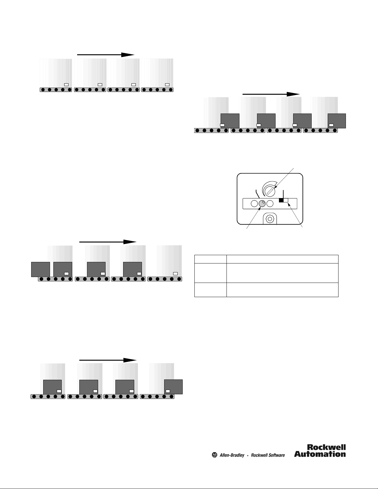
System Overview
Figure 1. System Overview
Direction of Product Flow
ZONE 4
ZONE 3 ZONE 2 ZONE 1
Slug Release
Unloading all accumulated product can be achieved by
activating the slug release signal. This will cause all zones to
drive without singulating (separating) the boxes.
Upon de-activation of the slug release signal, the system will
resume to normal accumulation.
P4 P3 P2 P1
The following section describes the general sequence of
operation of conveyors using the 44NSP Zero Pressure
Accumulation Sensor. These systems offer two modes of
accumulation that can be defined by the user: singulation
release and slug release. The loading and unloading of the
conveyor for both modes are described as follows:
Loading Product onto the Conveyor
Starting with your conveyor empty (no boxes present) and
your conveyor rollers active (running) a box placed on the
conveyor continues until it reaches the discharge zone (zone
1). As product passes through the loading zone (z one 4) a
gap will be formed equal to the zone length.
When box 1 reaches P1, zone 1 stops driv ing. A signal is sent
to zone 2 to indicate that zone 1 is occupied (see Figure 1).
When box 2 reaches P2, zone 2 stops driv ing. A signal is sent
to zone 3 to indicate that zone 2 is occupied. This sequence
is repeated until the conveyor is fully loaded
Figure 2. Loading the Conveyor
Direction of Product Flow
ZONE 4
P4 P3 P2 P1
ZONE 3 ZONE 2 ZONE 1
Unloading Product onto the Conveyor
Singulation Release
To unload box 1 from the discharge zone (zone1) activate the
zone release signal. When box 1 leaves P1, box 2 will move
to the next zone creating a gap between itself and box 3. This
sequence will be repeated until the conveyor has been
completely unloaded.
Figure 4. Slug Release of Accumulated Product
Direction of Product Flow
ZONE 4
P4 P3 P2 P1
ZONE 3 ZONE 2
ZONE 1
User Interface
Timer Adjustment Knob
(200 ms…10s)
(200 ms default setting)
TIMER
OUT
Output Indication
1 0
Selector Switch
Selector Switch Function
Position Description
Air-to-Drive. Sensor output is active (driving load) while
1
0
The on delay timer function can be used to delay the release
of product.
the reflector is unblocked. This is the factory default
setting.
Air-to-Break. Sensor output will be active (driving load)
while the reflector is blocked.
Figure 3. Singulation Release of Accumulated Product
Direction of Product Flow
ZONE 4
P4 P3 P2 P1
ZONE 3 ZONE 2
ZONE 1
Note: P1, P2, P3, P4 are used to reference 44N sensors in an
accumulation system.
2
Page 3

Approximate Dimensions [mm (in.)]
55.62 (2.19)
103.63 (4.08)
Max. Travel
31.75
(1.250)
40 (1.575)
5.21 (0.205) x
8.13 (0.320)
Slot, 2 Places
15.87 (0.625)
74.93
(2.950) Ref
32.66 (1.286)
41.91
(1.65)
5.46 (0.215)
M30 x 1.5 external
thread 1/2 in. NPSM
internal thread
30.35
(1.195)
Downstream Connection (Discharge End)
For Singulation Release:
To activate the singulation release signal connect pin 4 (black
wire using an 889D--F4BC--2 cable) to +24V DC. The
discharge zone will singulate as long as the singulation
release signal is active.
For Slug Release:
To activate the slug release signal connect pin 2 (white wire
using an 889D--F4BC--2 cable) to +24V DC. All the zones will
drive simultaneously without singulating (separating) the
boxes.
Upstream Connection (Infeed End)
304.88 mm (12 in.) cable on 44NSP--2JPBD--Z01. Female right angle pico (M8) QD on a
533.4 mm (21 in.) cable on 44NSP--2JPBD--Z02 and 44NSP--2JPBD--Z03.
Refer to page 1 for downstream and upstream cable lengths.
ZONE 4
ZONE 3 ZONE 2 ZONE 1
Direction of Product Flow
P4 P3 P2 P1
valve
Upstream Connection
valve
valve
valve
Downstream Connection
Wiring Diagrams
Upstream Downstream
(+)
2
3
5
4
Slug
1
Singulation
(--)
Female
Product comes with 22 AWG cable.
(Pin 1)
(Pin 2)
(Pin 4)
(Pin 3)
Blue
Brown
1
2
(Pin 1)
(Pin 2)
(Pin 4)
(Pin 3)
Output load 30V DC
100 mA, PNP
(+)
Slug
Singulation
(--)
2
3
4
Male
1
The 44N Zone Control sensor allows the user to monitor the
status of the infeed zone by using an 889D--M4BC--2 male
cordset connected to the upstream connection of the infeed
sensor.
The black wire of the 889D--M4BC--2 cordset provides this
signal. A voltage signal indicates that there is no object
blocking the infeed zone. A 0V DC signal indicates that the
infeed sensor is blocked.
The upstream connection output current is limited by a 3 kΩ
resistor, which would allow the sensor to drive certain I/O
cards. Rockwell Automation recommends the following I/O
cards for reliable output detection.
1769--IB16I
1756--IB32
1756--IB16
1769--1Q32
1769--1Q16
3
Page 4

PN--39825
10000024950 Ver 02
July 13, 2009
4
 Loading...