

Page 1
Installation Instructions
PHOTOSWITCHr Bulletin 44B Photoelectric Sensor
IMPORTANT: SAVE THESE INSTRUCTIONS FOR FUTURE USE.
Description
The Bulletin 44B photoelectric sensor
is intended for industrial applications
which require the reliable detection of
objects that fall close to a surface
which must be ignored. Unlike
standard diffuse style sensors, the
Bulletin 44B incorporates a dual
receiver optical system to actively “see”
both the target and the background
areas. This allows the sensor to
suppress any background reflections.
The Bulletin 44B photoelectric sensor
is available in two sensing modes with
a common mechanical optics system.
The difference between the two lies in
their operation. As shown to the right,
both sensing modes will actively “see”
the background condition using the
second internal receiver. The
background suppression sensing
mode will output when it “sees”
reflected light from the target. In
contrast, the foreground suppression
sensing mode will use the background
as a “reflector” and output when
sensed area is blocked by the target.
In general, the foreground suppression
sensing mode should be used when
looking at a dark, irregularly shaped
target on a highly reflective
background. Background suppression
sensing mode is well suited for light
targets on a less reflective background.
For added installation and
troubleshooting assistance, both
sensing modes contain a green LED
status indicator to warn the user of an
unstable application condition, i.e. dirty
lens, low contrast. This indicator will
remain steady ON during normal
operation, but flash to indicate a
change in the application environment.
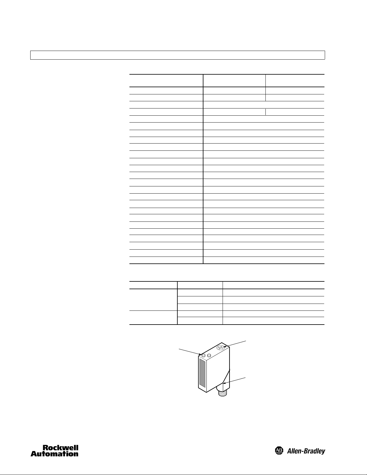
General Specifications
Catalog Number
Sensing Modes
Sensing Range
Light Source
Spot Size
Adjustment Knob
Unit Protection
Supply Voltage
Current Consumption
Maximum Leakage Current
Output Type
Output Mode
Output Rating
Response Time
Housing Material
Lens Material
LED Indicators
Connection Types
Supplied Accessories
Optional Accessories
Operating Environment
Vibration
Shock
Operating Temperature
Relative Humidity
Approvals
User Interface
Color
Green
Orange
44BSB- 1JBA1- D4
44BSB-1KBA1- D4
Background suppression (BGS)
30 to 300mm
880nm Infrared
20mm spot @ 300mm
6 turn to set cutoff point
Output short circuit, reverse polarity, overload, false pulse
20--30V DC
20mA maximum
10A
NPN and PNP
Light/dark operate by catalog number
100mA @ 24V DC
1ms maximum
High impact acrylic
High impact acrylic
See User Interface table below
4-pin DC micro on 90_ degree swivel
None
Cordsets, mounting brackets
NEMA 3, 4X, 6P, 12, 13 (IP67)
10--55Hz, 1mm amplitude, Meets or exceeds IEC 947--5--2
30G with 1ms pulse duration, Meets or exceeds IEC 947--5--2
-- 2 0 _Cto+70_C(--4_F to +158_F)
595%
UL listed, c--UL, CE marked for all applicable directives
State
OFF
ON
Flashing
OFF
ON
Sensor not powered, output active, SCP active
Sensor powered
Unstable margin
Output not activated
Output activated
44BSN- 1JBA1- D4
44BSN-1KBA1- D4
Foreground suppression (FGS)
30 to 200mm
15mm spot @ 200mm
Status
Features
S Adjustable background and
foreground suppression models
S Power, output, and stability status
indicators
S Micro QD connection with 90_
swivel
S Low voltage 24V DC operation
S Protected from miswiring
S Dual NPN and PNP outputs
S Fast 1ms response time
LED Status
Indicators
Adjustabl e
Knob
Micro QD
Swivel
1
Page 2
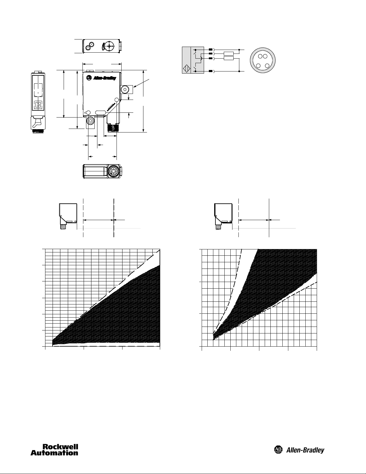
Dimensions—mm (inches)
14.99
(0.59)
42.55 (1.67)
51.18
(2.01)
63.50
(2.50)
13.97
(0.55)
Optional Mounti ng
Bracket and Screw
67.38
(2.65)
44B--BKT
Wiring Diagrams
NPN/PNP
1
Brown
Black
4
White
2
3
Blue
Quick-Disconnect
Micro
+
2
4
3
1
--
7.11
(0.28)
10
(0.39)
30.7 (1.21)
13.98
(0.55)
Typical Response Curve Typical Response Curve
Cutoff Point
Sensing Range
min
Background Suppression Foreground Suppression
300
250
200
150
Suppression Range Sensing Range
300
250
200
150
Suppression Range
min
Cutoff Point
100
Sensing Distance—mm (in)
50
0
0 100 200 300
Suppression Distan ce—mm (in)
100
Sensing Distance—mm (in)
50
0
0 100 20050
Suppression Distan ce—mm (in)
150
2
Page 3

Mounting the Sensor
The Bulletin 44B photoelectric sensor must be mounted on a
firm stable surface or support. A mounting which is subject to
excessive vibration or shifting may cause intermittent
operation of the sensor. Rockwell Automation offers a wide
variety of mounting brackets and quick-disconnect cables for
ease of installation. Refer to www.ab.com/sensors for a
complete listing of these products. Once securely mounted,
the sensor can be wired per the attached wiring diagrams.
Wiring the Sensor
The Bulletin 44B photoelectric sensor is available with a
micro quick-disconnect for ease of installation and
maintenance. Rockwell Automation recommends the use of
the 889 Series of cordsets and patchcords. All external
wiring should conform to the National Electric Code and/or all
applicable local codes.
Application Notes
Due to the detection method used by these sensors, it is
important that the sensor be mounted in such a way as to
ensure that the target passes in an orientation perpendicular
to the sensors lenses.
Example of Fixed Background Suppression
R1
R2
E1
Min
Target
Fixed Sensing
The gap between the target and background will vary with
the shape and reflectivity of the target. This variance is
known as the suppression quality and can be determined by
the response curves shown for the sensor.
Example of Adjustable Background Suppression
Cutoff
Range
Cutoff
R1 R2
E1
Min
Target
Adjustabl e
Sensing Range
R1 = Far
R2 = Near
R2 > R1:out = on
3
Page 4

Configuring the Sensor
(Background Suppression models)
Once securely installed, the sensing range of the sensor
must be set using the six turn adjustment knob on the top
cover. This knob is used to set the cutoff point (point at which
the background will be suppressed) of the sensor.
1. Apply power to the sensor and ensure that the green
power/stability LED turns ON.
2. Using an instrument screwdriver, adjust the sensor
background cutoff point to its minimum setting by turning
the knob counterclockwise until a “click” can be heard.
The raised dimple on the knob should be at roughly the
11 o’clock position.
3. The background cutoff point for the 44BSB sensor may
be set between 30mm and 300mm.
4. Set the background cutoff point by rotating the knob
clockwise until the orange status LED turns ON (OFF for
44BSB--1KBA1-- D4 models).
5. Rotate the background cutoff point knob
counterclockwise until the orange status LED just turns
OFF (ON for 44BSB--1KBA1--D4 models).
6. This indicates that the background has been sensed and
is being suppressed by the sensor. If the indicator does
not turn ON, it means that the background is beyond the
background cutoff point and will be ignored.
7. The sensor is now configured to detect targets between
30mm and this cutoff point. Note that the reflectivity of the
target will influence the distance between the background
and the cutoff point. As illustrated in the figure below, a
nonreflective target will require a greater gap due to the
smaller amount of light being returned to the sensor. Use
the enclosed response curves to help determine the
distance of this gap.
Application Example
Configuring the Sensor
(Foreground Suppression models)
Once securely installed, the sensing range of the sensor
must be set using the six turn adjustment knob on the top
cover. This knob is used to set the cutoff point (point at which
the foreground will be suppressed) of the sensor.
1. Apply power to the sensor and ensure that the green
power/stability LED turns ON.
2. Using an instrument screwdriver, adjust the sensor
foreground cutoff point to its minimum setting by turning
the knob counterclockwise until a “click” can be heard.
The raised dimple on the knob should be at roughly the
11 o’clock position.
3. The foreground cutoff point for the 44BSB sensor may be
set between 30mm and 150mm.
4. Set the foreground cutoff point by rotating the knob
clockwise until the orange status LED turns ON (OFF for
44BSB--1KBA1-- D4 models).
5. Continue rotating the knob clockwise until the orange
status LED turns OFF (ON for 44BSB--1KBA1--D4
models).
6. Rotate the foreground cutoff point knob counterclockwise
until the orange status LED just turns ON (OFF for
44BSN--1KBA1-- D4 models).
7. This indicates that the background has been sensed and
is being used as the target. When an object is placed
between the sensor lens and this point, it will be detected
due to the absence of reflected light.
8. As with the background suppression sensing modes, the
reflectivity of the target will influence the gap between the
target and the cutoff point. Use the enclosed response
curves to help determine the distance of this gap.
Application Example
PHOTOSWITCHR is a registered trademark of Rockwell Automation.
NorylR is a registered trademark of General Electric Company.
4
Publication 75051--037--01(A)
December 2004
PrintedinUSA
 Loading...