

Page 1

Enwatch
Installation Guide
Page 2
Important User Information
Solid state equipment has operational characteristics differing from those of
electromechanical equipment. Safety Guidelines for the Application, Installation and
Maintenance of Solid State Controls (Publication SGI-1.1 available from your local
Rockwell Automation sales office or online at http://www.ab.com/manuals/gi)
describes some important differences between solid state equipment and hard-wired
electromechanical devices. Because of this difference, and also because of the wide
variety of uses for solid state equipment, all persons responsible for applying this
equipment must satisfy themselves that each intended application of this equipment is
acceptable.
In no event will Rockwell Automation, Inc. be responsible or liable for indirect or
consequential damages resulting from the use or application of this equipment.
The examples and diagrams in this manual are included solely for illustrative purposes.
Because of the many variables and requirements associated with any particular
installation, Rockwell Automation, Inc. cannot assume responsibility or liability for
actual use based on the examples and diagrams.
No patent liability is assumed by Rockwell Automation, Inc. with respect to use of
information, circuits, equipment, or software described in this manual.
Reproduction of the contents of this manual, in whole or in part, without written
permission of Rockwell Automation, Inc. is prohibited.
Throughout this manual we use notes to make you aware of safety considerations.
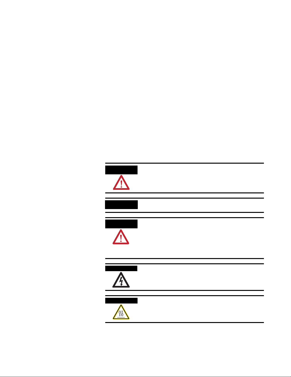
WARNING
IMPORTANT
ATTENTION
SHOCK HAZARD
BURN HAZARD
Identifies information about practices or circumstances
that can cause an explosion in a hazardous environment,
which may lead to personal injury or death, property
damage, or economic loss.
Identifies information that is critical for successful
application and understanding of the product.
Identifies information about practices or circumstances
that can lead to personal injury or death, property
damage, or economic loss. Attentions help you:
• identify a hazard
• avoid a hazard
• recognize the consequence
Labels may be located on or inside the drive to alert
people that dangerous voltage may be present.
Labels may be located on or inside the drive to alert
people that surfaces may be dangerous temperatures.
Emonitor and Enwatch are registered trademarks and gSE and Spike Energy are a trademarks of Rockwell Automation, Inc..
All other trademarks are the property of their respective holders and are hereby acknowledged.
Page 3

Important User Information . . . . . . . . . . . . . . . . . . . . . . . . . . . . . . . . . . ii
Table of Contents Chapter 1
Installing the Enwatch
Introduction . . . . . . . . . . . . . . . . . . . . . . . . . . . . . . . . . . . . . . . . . . . . . . . 1
Installation . . . . . . . . . . . . . . . . . . . . . . . . . . . . . . . . . . . . . . . . . . . . . . . . 2
Electrical. . . . . . . . . . . . . . . . . . . . . . . . . . . . . . . . . . . . . . . . . . . . . . . 2
Mechanical . . . . . . . . . . . . . . . . . . . . . . . . . . . . . . . . . . . . . . . . . . . . . 3
Rockwell Automation Support . . . . . . . . . . . . . . . . . . . . . . . . . . . . . . . . 3
Electrical Connections . . . . . . . . . . . . . . . . . . . . . . . . . . . . . . . . . . . . . . . 4
Connectors. . . . . . . . . . . . . . . . . . . . . . . . . . . . . . . . . . . . . . . . . . . . . 5
Analog Input Configuration . . . . . . . . . . . . . . . . . . . . . . . . . . . . . . . 7
LEDs . . . . . . . . . . . . . . . . . . . . . . . . . . . . . . . . . . . . . . . . . . . . . . . . . 8
Trigger Isolation Jumpers . . . . . . . . . . . . . . . . . . . . . . . . . . . . . . . . . 9
Normal Operation versus Monitor Mode . . . . . . . . . . . . . . . . . . . . 9
Serial Port (RS-232) . . . . . . . . . . . . . . . . . . . . . . . . . . . . . . . . . . . . . 10
Supply Voltage . . . . . . . . . . . . . . . . . . . . . . . . . . . . . . . . . . . . . . . . . 10
Flash Memory . . . . . . . . . . . . . . . . . . . . . . . . . . . . . . . . . . . . . . . . . 11
On Board Monitor . . . . . . . . . . . . . . . . . . . . . . . . . . . . . . . . . . . . . . . . . 11
Setting Up an Enwatch Unit . . . . . . . . . . . . . . . . . . . . . . . . . . . . . . . . . 11
Connecting Transducers . . . . . . . . . . . . . . . . . . . . . . . . . . . . . . . . . . . . 16
Connecting an ICP Accelerometer . . . . . . . . . . . . . . . . . . . . . . . . . 17
Connecting a Coil-Based Velocity Sensor . . . . . . . . . . . . . . . . . . . 18
Connecting an Process DC Voltage Signal. . . . . . . . . . . . . . . . . . . 19
Connecting a Magnetic Hall Effect Sensor. . . . . . . . . . . . . . . . . . . 20
Enwatch Measurement Capabilities . . . . . . . . . . . . . . . . . . . . . . . . . . . 21
Setting Up Sample Measurements. . . . . . . . . . . . . . . . . . . . . . . . . . 25
Configuration of Emonitor with Enwatch . . . . . . . . . . . . . . . . . . . . . . 32
Table of Contents
Chapter 2
Specifications
Index
iii Publication GMSI10-UM031C-EN-E - July 2005
Power Ratings . . . . . . . . . . . . . . . . . . . . . . . . . . . . . . . . . . . . . . . . . 41
Temperature Ratings . . . . . . . . . . . . . . . . . . . . . . . . . . . . . . . . . . . . 41
Page 4

Table of Contents iv
Publication GMSI10-UM031C-EN-E - July 2005
Page 5
Chapter
1
Installing the Enwatch
This manual introduces you to the Allen Bradley Enwatch® unit. The manual
is intended for anyone who installs, tests, or configures the Enwatch hardware.
It does not cover using the Enwatch unit to collect data. For information on
collecting data with the Enwatch unit, refer to the Online Applications Guide
provided with your Emonitor
®
online system.
Introduction
CHANNEL
ICP 1
ICP 2
ICP 16
External Trig. 1 - Event
External Trig. 4
Enwatch is a distributed network system providing 16 channels of analog
inputs together with 4 trigger channels. The unit includes signal conditioning
and analog to digital conversion. It allows you to connect 16 two-wire ICP or
other sensors into your Emonitor Online system. Each Enwatch unit is a
microprocessor-based system, complete with network controller that carries
out data acquisition tasks as directed by an Emonitor unload station. A typical
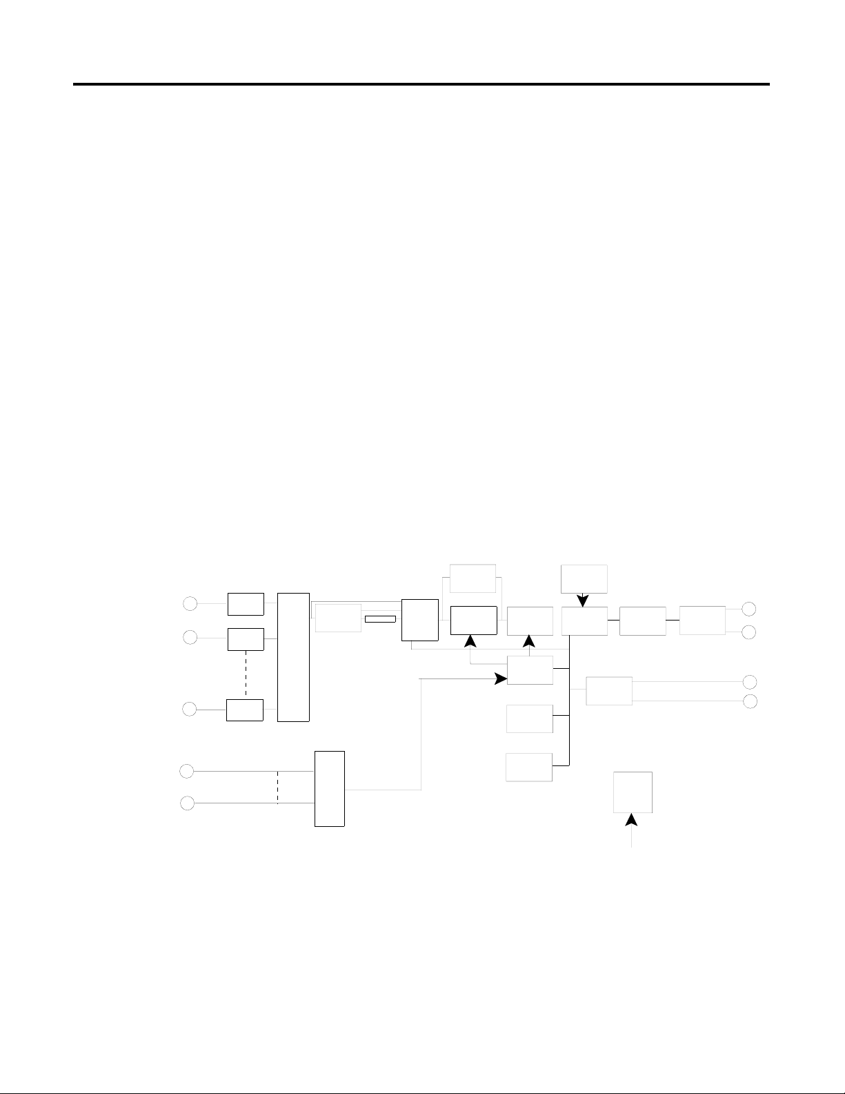
diagram for an Enwatch unit is shown in Figure 1.1, below.
Figure 1.1 Enwatch diagram
gSE
HP Filters
15:1
Bias Check
Multiplexer
4:1
Aux.
Intergrator
Programable
Gain
Select
Programable
Anti-Alias
Filter
A to D
Converter
Clock
Generator
Flash
SRAM
Watchdog
Microprocessor
RS-232
Ethernet
Controller
Power
Regulation
10Base-T
DC in
The Enwatch unit responds to all relevant network data exchanges as defined
by the Ethernet protocol using the UDP/IP standard. In addition, there is a
comprehensive on-board monitor program that can exercise all functions via
the on-board serial RS232 port.
1 Publication GMSI10-UM031C-EN-E - January 2009
Page 6

2 Installing the Enwatch
Installation
The Enwatch unit is easy to install. The enclosure is mounted using four
screws. Cables are terminated on removable screw terminal blocks, making
installation and service simple. Network cables are terminated on the board
using a a standard RJ-45 connector.
Each Enwatch board has four status LEDs to monitor system activity. In the
unlikely event of a system problem, a portable PC can be used to diagnose the
problem using the RS-232 serial interface on each Enwatch board.
Prior to installation, the only set-up required is to assign an IP address, Subnet
Mask, and Gateway IP address (if available) to the node. This must be a unique
address on the network. You assign the IP address by connecting a terminal
(or PC in terminal mode) to the on-board RS-232 port and using the on-board
monitor program. See “Setting Up an Enwatch Unit” on page 11 for more
information.
Electrical
The circuit board is a completely self-contained 16-channel analog input to
Ethernet interface, including power regulation and local communication
facilities. A block diagram of the board is shown in Figure 1.1 on page 1. Each
block of the diagram is described below.
• ICP interface - Each of the 16 channels has its own ICP interface that
is capable of powering a typical two-wire ICP transducer. The nominal
voltage is 24 V with a constant current of 3.6 mA. A typical transducer
has a bias voltage value of around 11 V, so that the system can
accommodate a full ±10V input range. The ICP interface can be
disabled for AC and DC coupling of voltage signals.
• Multiplexer - The multiplexer circuit selects one of the 16 input
channels under software control. All inputs are over-voltage and ESD
protected.
• High pass filters - Four software-programmable high-pass filters
(0.36 Hz, 2.67 Hz, 5.3 Hz, and 23.8 Hz) are available to remove
unwanted low frequency signals.
• Integrator - An on-board hardware integrator is available for getting a
velocity measurement from an accelerometer, as well as displacement
from a velocity sensor. The host software can perform a second level of
integration if required.
• Spike Energy™ function (gSE™) - gSE provides a conditioned
signal suitable for measurement of bearing condition.
• Anti-aliasing filter - This filter removes high-frequency components
from the incoming analog signal that might alias back into the sampled
signal, resulting in incorrect data in the spectrum. The filter has a very
high roll-off and removes all alias effects in standard sampling/spectral
analysis applications.
Publication GMSI10-UM031C-EN-E - January 2009
Page 7

Installing the Enwatch 3
• Analog-to-digital converter (ADC) - The ADC samples up to
51.2 kHz and has 16-bit resolution, providing a theoretical dynamic
range of 96 dB.
• Clock generator - The timer varies the sampling rate under
microprocessor control. Sampling can be synchronized to one of 4
external triggers (typically a once-per-rev TTL signal from a rotating
shaft). This system can also take a preprogrammed number of samples
per revolution. The external trigger acts as a tachometer to determine
shaft speed. Pre and post-trigger functions are available.
• Gain amplifier - The Enwatch unit automatically sets the input gain in
auto-range mode as each channel is selected by the multiplexer.
• Microprocessor subsystem - This comprises the microprocessor,
flash memory, and SRAM memory. The microprocessor controls the
Enwatch unit under instructions stored in the flash memory. The SRAM
memory acts as a temporary data storage area if buffering is required
before data is transferred over the network.
• Watchdog - The microprocessor subsystem incorporates a watchdog
facility that, if a power glitch or other external effect interrupts the
system, automatically resets without the need for user intervention.
• Ethernet controller/buffer memory/10Base-T - These functions
control data transfer over the Ethernet network. The system uses the
UDP/IP standard protocol and implements 10 Base-T as the physical
network layer.
• Power regulation - Input DC power is derived from an AC to DC
converter (not shown in Figure 1.1) and the Power Regulation function
provides the secondary DC voltages as required.
Rockwell Automation Support
Mechanical
The Enwatch unit is comprised of a single circuit board housed in a sealed (IP
66) enclosure. Each system has its own self-contained power supply, and
terminals for the input, power, tachometer, and network cables.
Rockwell Automation provides technical information on the Web to assist you
in using its products. At http://support.rockwellautomation.com
technical manuals, a knowledge base of FAQs, technical and application notes,
sample code and links to software service packs, and a MySupport feature that
you can customize to make the best use of these tools.
For an additional level of technical phone support for installation,
configuration, and troubleshooting, we offer TechConnect support programs.
For more information, contact your local distributor or Rockwell Automation
representative, or visit http://support.rockwellautomation.com
Publication GMSI10-UM031C-EN-E - January 2009
, you can find
.
Page 8
4 Installing the Enwatch
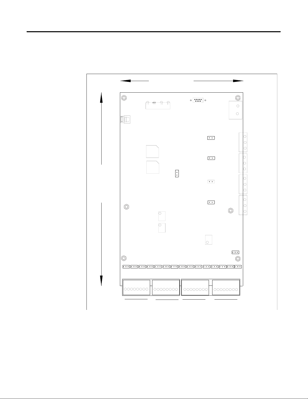
Electrical Connections
9.25"
(235 mm)
This section describes the electrical connections on the Enwatch board, shown
in Figure 1.2, below.
Figure 1.2 Enwatch electrical connections
6.75" (170 mm)
J11
JP 20
JP 19
JP 18
JP 17
J9
_
+
DC Power In
J6
J5
J4
J3
4
33
22
1
3
33
Ext. Trigger
22
Input Terminal
1
Block
33
2
22
1
1
33
22
1
J8
Status LED's
Network Input
RJ-45 Jack
RX LK OB
TX
U28
U20
Normal / Monitor
Mode Select
RS-232
DB-9 (female)
JP 21
RV2
RV3
Analog Input Configuration Jumpers
A - B A - B A - B A - B A - B A - B
1 - 2 - 3 - 4 - 5 - 6 - 7 - 8 9-10-11-12-13-14-15-16 1 - 2 - 3 - 4 - 5 - 6 - 7 - 8
A - B A - B A - B A - B A - B
A - B
J1
Input Connector Block
RV1
9-10-11-12-13-14-15-16
J2
A - B
A - B
A - B
A - B
Publication GMSI10-UM031C-EN-E - January 2009
Page 9

Installing the Enwatch 5
Connectors
The Enwatch unit has 11 connectors labeled J1 to J11 as shown in Table 1.1.
Table 1.1 Enwatch connectors
Connector No. of Pins Function
J1 16 Analog input channels 1–8
J2 16 Analog input channels 9–16
J3 3 External trigger 1 / event 1
J4 3 External trigger 2 / event 2
J5 3 External trigger 3
J6 3 External trigger 4
J7 5 Test points (service use only)
J8 8 Ethernet interface
J9 2 Supply voltage
J10 2 Spare
J11 9 Serial port (RS-232)
The location of the connectors is shown in Figure 1.2 on page 4. The pin
outputs are listed in the following tables.
Table 1.2 J1 and J2 pin outputs
J1: Analog Inputs 1-8 J2: Analog Inputs 9-16
Signal Pin No Signal Pin No.
CH 1 input
CH 1 ground
CH 2 input
CH 2 ground
CH 3 input
CH 3 ground
CH 4 input
CH 4 ground
CH 5 input
CH 5 ground
CH 6 input
CH 6 ground
CH 7 input
CH 7 ground
CH 8 input
CH 8 ground
1
2
3
4
5
6
7
8
9
10
11
12
13
14
15
16
CH 9 input
CH 9 ground
CH 10 input
CH 10 ground
CH 11 input
CH 11 ground
CH 12 input
CH 12 ground
CH 13 input
CH 13 ground
CH 14 input
CH 14 ground
CH 15 input
CH 15 ground
CH 16 input
CH 16 ground
1
2
3
4
5
6
7
8
9
10
11
12
13
14
15
16
Publication GMSI10-UM031C-EN-E - January 2009
Page 10

6 Installing the Enwatch
Table 1.3 J3 External trigger pin outputs
Signal Pin No. Notes
Power supply 1 See note 1 on page 7.
Input 2 See note 2 on page 7.
Ground 3
Table 1.4 J4 External trigger pin outputs
Signal Pin No. Notes
Power supply 1 See note 1 on page 7.
Input 2 See note 2 on page 7.
Ground 3
Table 1.5 J5 External trigger pin outs
Signal Pin No. Notes
Power supply 1 See note 1 on page 7.
Input 2 See note 2 on page 7.
Ground 3
Table 1.6 J6 External trigger pin outputs
Signal Pin No. Notes
Power supply 1 See note 1 on page 7.
Input 2 See note 2 on page 7.
Ground 3
Table 1.7 J8 Ethernet connection pin outputs
Common RJ-45
Publication GMSI10-UM031C-EN-E - January 2009
Page 11

Installing the Enwatch 7
Table 1.8 J9 Supply voltage pin outputs
Signal Pin No.
Positive supply voltage +
Common -
Table 1.9 J10 pin outputs
Not user accessible
Table 1.10 J11 Serial port (RS-232) pin outputs
Signal Pin No. Notes
TXD 1 To connect to a host computer, use a
RXD 2
Ground 3
null modem 9-pin female to 9-pin
female cable.
Notes:
1. A supply voltage is available on pin 1 of the connector to power an
external trigger device. The voltage is equal to the voltage of the
incoming power supply to the board (on connector J9).
2. The external trigger is compatible with a CMOS/TTL logic level (5 V
logic). Alternatively, any voltage input in the range 5 to 24 V can be
accommodated. The trigger can be isolated or non-isolated.
Analog Input Configuration
The 16 analog inputs provide you three options for signal coupling using a
3-way configurable jumper. The three positions are described in Table 1.11.
Table 1.11 Analog input options
Position Description
ICP Interface (nominal 24 V supply at 3.6 mA constant current for
transducer powering)
DC DC coupled
AC AC coupled
Publication GMSI10-UM031C-EN-E - January 2009
Page 12

8 Installing the Enwatch
Each channel (16 total) has a 3-way header associated with it. These are labeled
with the channel number and “A” or “B.” The three jumper options are:
• Fitted to position xA
• Fitted to position xB
• Not fitted
where x is the channel number 1-16.
x B
Position Coupling
x A ICP
x B DC Coupled
Not Fitted AC Coupled
x A
IMPORTANT
The -3dB point of the high-pass coupling for the ICP
interface and AC Coupled configuration is 0.07 Hz.
LEDs
Four LEDs, as shown in Figure 1.2 on page 4, indicate the status of the
Ethernet communication. These illuminate as described in Table 1.12.
Table 1.12 LEDs
LED Description
OB The Enwatch unit is accessing LAN controller
LK Communication link is established between Enwatch unit and
network
RX Data is being received
TX Data is being transmitted
Publication GMSI10-UM031C-EN-E - January 2009
Page 13

Installing the Enwatch 9
Trigger Isolation Jumpers
Four jumpers, JP17 to JP20, are sited on the board to enable the four trigger
inputs to be isolated or non-isolated. Non-isolated means the common of the
trigger input can be connected to the common of the Enwatch unit. With a
jumper removed, the trigger is isolated. Table 1.13 summarizes the jumper
positions.
Table 1.13 Jumper positions
Mode Jumper
External trigger 1 isolated JP17 Out
External trigger 1 non-isolated JP 17 In
External trigger 2 isolated JP18 Out
External trigger 2 non-isolated JP18 In
External trigger 3 isolated JP19 Out
External trigger 3 non-isolated JP19 In
External trigger 4 isolated JP20 Out
External trigger 4 non-isolated JP20 In
IMPORTANT
If an external sensor is to be used that is powered from pin
1 of J3, J4, J5 or J6, then the jumper corresponding to the
trigger channel must be inserted to provide a ground return
path for the sensor power.
Normal Operation versus Monitor Mode
The Enwatch unit incorporates an on-board monitor program for checking
the unit and modifying the system’s IP address. Inserting a jumper in JP21
enters into monitor mode.
Table 1.14 Normal vs. monitor mode
Mode Jumper J21
Normal Out
Monitor In
Publication GMSI10-UM031C-EN-E - January 2009
Page 14

10 Installing the Enwatch
Serial Port (RS-232)
An RS-232 compatible serial port is available on connector J11 for providing
local communication with the board (independent of the Ethernet network).
Only RXD and TXD lines are supported, and so a null modem cable must be
used. An on-board software monitor is provided to communicate through the
serial port.
If you do not use a 9-pin female to female null modem cable, the
recommended cable connection to a PC is shown in Table 1.15.
Table 1.15 J11 cable connections
J11 9-Pin D-Shell Connector
12
23
35
Supply Voltage
Incoming supply voltage to the power supply is 80 to 240 VAC / 50 or 60 Hz.
The power supply should be rated for a minimum of 1 A. If you have an
ISSUE F board, set the AC to DC power supply output voltage to 9 VDC. All
ISSUE G boards and higher, require a 24 VDC power supply. The power
supply that comes with the ISSUE G boards is pre set to 24 VDC and should
not be adjusted.
WARNING
TIP
Never attempt to connect the ISSUE F board to a 24V
power supply as doing this will damage the board. Always
ensure you have the proper power supply for the board
ISSUE you are using. The 24VDC power supply for ISSUE
G and higher boards has a yellow label that is marked
24VDC. The 12VDC power supply for ISSUE F boards
has a blue label that is marked 12VDC.
The ISSUE letter is located on the board. ISSUE F is
located at the bottom edge of the board near the J2
connector. See Figure 1.2 on page 4.
Publication GMSI10-UM031C-EN-E - January 2009
The ISSUE letter for ISSUE G and higher boards is
located in the upper left corner of the board, near the J8
connector.
Page 15

Installing the Enwatch 11
Flash Memory
If it is necessary to change the firmware, the flash memory is located in
position U20 and U28 (see Figure 1.2 on page 4). This flash memory is socket
mounted to allow you to change the EPROM. Make sure that the orientation
of the chip is correct when installing.
On Board Monitor
Setting Up an Enwatch Unit
When you insert a jumper into JP21, the Enwatch unit operates in its internal
monitor mode. This enables you to change the IP address as well as modify
other options. To invoke monitor mode, connect a terminal (or PC computer
in terminal mode) to the serial port and insert a jumper at position JP21.
Remove the power and then reconnect the power to reset the unit. A sign-on
message appears on the terminal together with a list of options (described in
“Setting Up an Enwatch Unit”, below).
To exit monitor mode, simply remove the jumper at position JP21, then
remove and reconnect the power to reset the unit.
Before installation, make sure you have plant specific IP network addresses
available for each Enwatch unit. For convenience write them down here.
IP Address 1: ____________________ IP Address 6: ____________________
IP Address 2: ____________________ IP Address 7: ____________________
IP Address 3: ____________________ IP Address 8: ____________________
IP Address 4: ____________________ IP Address 9: ____________________
IP Address 5: ____________________ IP Address 10: ___________________
You should also know the Subnet Mask and Gateway IP address (if available)
for each Enwatch unit.
1. Attach the Enwatch unit to the test computer via the RS-232 (serial)
port using a null modem cable.
2. Make sure the jumper in the middle of the Enwatch unit board is
inserted (JP21).
3. Start up any terminal program (Winterm, QVT/Term, Procomm,
etc.…) and set it up to communicate through the serial port at 9600
Baud, No parity, 8 data bits, and 1 stop bit.
Publication GMSI10-UM031C-EN-E - January 2009
Page 16

12 Installing the Enwatch
4. Turn on the Enwatch unit. It should display its configuration, then a
configuration menu in the terminal window.
---------- Start monitor com port: COM1 9600 N81
Intelligent Transducer Adapter Type 1) V 1.2
Copyright Icon Research Ltd 1998/99
Main Menu:
1 - Exercise Hardware Control
2 - Exercise Memory Devices
3 - Exercise Ethernet Controller
4 - Exercise Combined Sub-Systems
5 - Configure Adapter Settings
6 - Enter Download Mode
Make your selection (1-6) : 5
5. Select 5- Configure Adapter Settings.
Intelligent Transducer Adapter Type 1) V 1.2
Copyright Icon Research Ltd 1998/99
Configure Adapter Menu:
1 - Default Settings
2 - Assign Host MAC
3 - Assign Host IP
4 - Assign Host UDP Port
5 - Assign Subnet Mask
6 - Assign Gateway IP
7 - Assign Name
8 - Assign Network Option
9 - Assign Debug Level
ESC - Back to Main Menu
6. Select 2 - Assign Host MAC, and set it to the MAC address from the
board by pressing ESC.
Intelligent Transducer Adapter Type 1) V 1.2
Copyright Icon Research Ltd 1998/99
Configure Adapter Menu:
1 - Default Settings
2 - Assign Host MAC
3 - Assign Host IP
4 - Assign Host UDP Port
5 - Assign Subnet Mask
6 - Assign Gateway IP
7 - Assign Name
8 - Assign Network Option
9 - Assign Debug Level
ESC - Back to Main Menu
Make your selection (1-9) : 2
Assigning Host MAC
Current Host MAC : 00-50-C2-02-00-01
Enter New Address or ESC to abandon :
Aborted Input - Host MAC unchanged
Publication GMSI10-UM031C-EN-E - January 2009
Page 17

Installing the Enwatch 13
7. Select 3 - Assign Host IP, and set your Enwatch unit to one of your
plant specific IP addresses.
Intelligent Transducer Adapter Type 1) V 1.2
Copyright Icon Research Ltd 1998/99
Configure Adapter Menu:
1 - Default Settings
2 - Assign Host MAC
3 - Assign Host IP
4 - Assign Host UDP Port
5 - Assign Subnet Mask
6 - Assign Gateway IP
7 - Assign Name
8 - Assign Network Option
9 - Assign Debug Level
ESC - Back to Main Menu
Make your selection (1-9) : 3
Assigning Host IP
Current Host IP : 200.100.200.100
Enter New Address or ESC to abandon :
8. Select 4 - Assign Host UDP Port, and set it to 4242. This is the default
port number and cannot be any other number.
Intelligent Transducer Adapter Type 1) V 1.2
Copyright Icon Research Ltd 1998/99
Configure Adapter Menu:
1 - Default Settings
2 - Assign Host MAC
3 - Assign Host IP
4 - Assign Host UDP Port
5 - Assign Subnet Mask
6 - Assign Gateway IP
7 - Assign Name
8 - Assign Network Option
9 - Assign Debug Level
ESC - Back to Main Menu
Make your selection (1-9) : 4
Assigning Host UDP Port
Current Host UDP Port : 4242
Enter New Port or ESC to abandon :
Publication GMSI10-UM031C-EN-E - January 2009
Page 18

14 Installing the Enwatch
9. Select 5 - Assign Subnet Mask, and set it to the number obtained from
the IT department. Normally it is 255.255.255.000
Intelligent Transducer Adapter Type 1) V 1.2
Copyright Icon Research Ltd 1998/99
Configure Adapter Menu:
1 - Default Settings
2 - Assign Host MAC
3 - Assign Host IP
4 - Assign Host UDP Port
5 - Assign Subnet Mask
6 - Assign Gateway IP
7 - Assign Name
8 - Assign Network Option
9 - Assign Debug Level
ESC - Back to Main Menu
Make your selection (1-9) : 5
Assigning Subnet Mask
Current Subnet Mask : 255.255.255.000
Enter New Address or ESC to abandon :
10. Select 6 - Assign Gateway IP, and set it to the number obtained from
the IT department.
Intelligent Transducer Adapter Type 1) V 1.2
Copyright Icon Research Ltd 1998/99
Configure Adapter Menu:
1 - Default Settings
2 - Assign Host MAC
3 - Assign Host IP
4 - Assign Host UDP Port
5 - Assign Subnet Mask
6 - Assign Gateway IP
7 - Assign Name
8 - Assign Network Option
9 - Assign Debug Level
ESC - Back to Main Menu
Make your selection (1-9) : 6
Assigning Gateway IP
Current Gateway IP : 255.255.255.255
Enter New Address or ESC to abandon :
Publication GMSI10-UM031C-EN-E - January 2009
Page 19

Installing the Enwatch 15
11. Select 8 - Assign Network Option, and set it to the 10 Base T Port.
Intelligent Transducer Adapter Type 1) V 1.2
Copyright Icon Research Ltd 1998/99
Configure Adapter Menu:
1 - Default Settings
2 - Assign Host MAC
3 - Assign Host IP
4 - Assign Host UDP Port
5 - Assign Subnet Mask
6 - Assign Gateway IP
7 - Assign Name
8 - Assign Network Option
9 - Assign Debug Level
ESC - Back to Main Menu
Make your selection (1-9) : 8
Assigning Network Option
Currently using Ethernet 10 Base T Port
Network Options Available:
1 : Ethernet 10 Base T
2 : Ethernet 10 Base 2
Enter New Network or ESC to abandon :
12. Select 9 - Assign Debug Level, and set it to OFF unless you want to
see the debug messages from the Enwatch unit.
Intelligent Transducer Adapter Type 1) V 1.2
Copyright Icon Research Ltd 1998/99
Configure Adapter Menu:
1 - Default Settings
2 - Assign Host MAC
3 - Assign Host IP
4 - Assign Host UDP Port
5 - Assign Subnet Mask
6 - Assign Gateway IP
7 - Assign Name
8 - Assign Network Option
9 - Assign Debug Level
ESC - Back to Main Menu
Make your selection (1-9) : 9
Assigning Debug Level
Debug Options Available:
0 : Off
1 : Basic System Sampling & Message Processing
2 : (1) + Full Rx & Tx Message Display
3 : (2) + Interrupt Firing Notifications
Debug Level 1 Currently Set
Enter New Debug Level or ESC to abandon :
13. Shut down the Enwatch unit by removing the AC power, and turn it
back on. Look at the configuration settings and make sure the MAC and
IP address are correct.
Publication GMSI10-UM031C-EN-E - January 2009
Page 20

16 Installing the Enwatch
14. Shut down the Enwatch unit by removing the AC power, then remove
the jumper in the center of the board (JP21) and connect the board to
an active Ethernet connection. You do not have to disconnect the
RS-232 port.
15. Open a DOS prompt on a networked computer. Type ping, then a
space, and then the first IP address.
Connecting Transducers
EXAMPLE
16. You should get a return response from the Enwatch unit.
The following sections show how to connect transducers to the Enwatch
terminals.
ping 200.100.200.100
Publication GMSI10-UM031C-EN-E - January 2009
Page 21

Installing the Enwatch 17
Connecting an ICP Accelerometer
The following diagram shows the wiring from an ICP accelerometer to the
terminals of the Enwatch unit.
TYPICAL WIRING FOR ICP ACCELEROMETER
J11
JP 20
JP 19
JP 18
JP 17
J9
DC Power In
_
+
J6
33
4
22
1
J5
J4
J3
3
33
22
1
33
2
22
1
1
33
22
1
J8
Network Input
RJ-45 Jack
RX LK OB
TX
Status LED's
U28
U20
Normal / Monitor
Mode Select
RS-232
DB-9 (female)
JP 21
RV2
A - B
Jumper in xA position
for ICP Accelerometer
Terminal 1 - Signal
Terminal 2 - Ground
RV3
A - B A - B A - B A - B A - B A - B
1 - 2 - 3 - 4 - 5 - 6 - 7 - 8 9-10-11-12-13-14-15-16 1 - 2 - 3 - 4 - 5 - 6 - 7 - 8
A - B A - B A - B A - B A - B
A - B
Shield Ground
Pin A - Signal
Pin B - Ground
Cable shield not
connected at this end
RV1
9-10-11-12-13-14-15-16
A - B
A - B
A - B
A - B
Publication GMSI10-UM031C-EN-E - January 2009
Page 22
18 Installing the Enwatch
Connecting a Coil-Based Velocity Sensor
The following diagram shows the wiring from a coil-based velocity sensor to
the terminals of the Enwatch unit.
TYPICAL WIRING FOR COIL-BASED VELOCITY SENSOR
J11
JP 20
JP 19
JP 18
JP 17
J9
DC Power In
_
+
J6
33
4
22
1
J5
J4
J3
3
33
22
1
33
2
22
1
1
33
22
1
J8
Network Input
RJ-45 Jack
RX LK OB
TX
Status LED's
U28
U20
Normal / Monitor
Mode Select
RS-232
DB-9 (female)
JP 21
RV2
A - B
No Jumper for
Velocity Sensor
Terminal 1 - Signal
Terminal 2 - Ground
RV3
A - B A - B A - B A - B A - B A - B
1 - 2 - 3 - 4 - 5 - 6 - 7 - 8 9-10-11-12-13-14-15-16 1 - 2 - 3 - 4 - 5 - 6 - 7 - 8
A - B A - B A - B A - B A - B
A - B
Shield Ground
Pin A - Signal
Pin B - Ground
Cable shield not
connected at this end
RV1
9-10-11-12-13-14-15-16
A - B
A - B
A - B
A - B
Publication GMSI10-UM031C-EN-E - January 2009
Page 23

Installing the Enwatch 19
Connecting an Process DC Voltage Signal
The following diagram shows the wiring from a process DC voltage signal to
the terminals of the Enwatch unit.
TYPICAL WIRING FOR PROCESS DC VOLTAGE SIGNAL
J11
JP 20
JP 19
JP 18
JP 17
J9
DC Pow er In
_
+
J6
33
4
22
1
J5
J4
J3
3
33
22
1
33
2
22
1
1
33
22
1
J8
Network Input
RJ-45 Jack
RX LK OB
TX
Status LED's
U28
U20
Normal / Monitor
Mode Select
RS-232
DB-9 (female)
JP 21
RV2
A - B
Jumper in xB position
for DC Signal
Terminal 1 - Signal
Terminal 2 - Ground
RV3
A - B A - B A - B A - B A - B A - B
1 - 2 - 3 - 4 - 5 - 6 - 7 - 8 9-10-11-12-13-14-15-16 1 - 2 - 3 - 4 - 5 - 6 - 7 - 8
A - B A - B A - B A - B A - B
A - B
Shield Ground
Cable shield not
connected at this end
RV1
A - B
A - B
9-10-11-12-13-14-15-16
Process DC
Source
A - B
A - B
Publication GMSI10-UM031C-EN-E - January 2009
Page 24

20 Installing the Enwatch
Connecting a Magnetic Hall Effect Sensor
The following diagram shows the external trigger wiring from a magnetic Hall
effect sensor (magnetic interrupter) to the terminals of the Enwatch unit.
TYPICAL WIRING FOR MAGNETIC HALL EFFECT SENSOR
J8
Network Input
RJ-45 Jack
RX LK OB
TX
Status LED's
U28
U20
Normal / Monitor
Mode Select
JP 21
RV2
RS-232
DB-9 (female)
J11
JP 20
JP 19
JP 18
JP 17
J9
DC Power In
_
+
4
J6
33
22
1
3
J5
33
22
1
2
J4
33
22
1
1
J3
Ground
33
Input
22
Power
1
A - B A - B A - B A - B A - B A - B
1 - 2 - 3 - 4 - 5 - 6 - 7 - 8 9-10-11-12-13-14-15-16 1 - 2 - 3 - 4 - 5 - 6 - 7 - 8
IMPORTANT
RV3
RV1
A - B
A - B A - B A - B A - B A - B
A - B
9-10-11-12-13-14-15-16
A - B
A - B
A - B
If an external sensor is to be used that is powered from pin
1 of J3, J4, J5 or J6, then the jumper corresponding to the
trigger channel must be inserted to provide a ground return
path for the sensor power. See “Trigger Isolation Jumpers”
on page 9.
Publication GMSI10-UM031C-EN-E - January 2009
Page 25

Installing the Enwatch 21
Enwatch Measurement
This section lists the measurement capabilities of the Enwatch unit.
Capabilities
Table 1.16 Enwatch measurement capabilities
Product Feature Capability
Signal Control Raw input signal
Integrated input signal via HP filter
Hp filter input signal
gSE 200 Hz input signal
gSE 5000 Hz input signal
Bias Voltage
Combining measurements in the Enwatch
driver
How does the Enwatch driver choose the
high pass filter?
The Enwatch driver can combine measurements at the same location in Emonitor. The
following items must to be the same to combine measurements.
Signal route control (Integrate/non integrate/gSE/Raw)
Tachometer on/off
gSE time constant
Sample rate/maximum frequency
Phase lock loop
Number of averages
Measurement filter
Number of lines
X=2 x FMAX/lines
If X > 5.3 then set to 23.8
else if X > 2.67 set to 5.3
else if X > 0.36 set to 2.67
else if the Smart HP filter is on in Emonitor, then set to 2.67, otherwise set to 0.36
Note: The Smart HP filter in Emonitor does not use 0.36Hz HP filter.
Trigger usage Sample on trigger (the first version of Enwatch always uses this option)
Sample on post-trigger
Sample on pre-trigger
Tachometer usage Use tachometer for PLL (phase loop locked)
Autorange Always on, maximum input ±10 V
Integrator reset control Reset before first sampling of a measurement
Publication GMSI10-UM031C-EN-E - January 2009
Page 26

22 Installing the Enwatch
Table 1.16 Enwatch measurement capabilities
Product Feature Capability
Sampling rate 64 to 51200 Hz by 1
FMAX Sampling Rate FMAX Sampling Rate
25 64 2000 5120
50 128 3200 8192
100 256 4000 10240
200 512 5000 12800
400 1024 6400 16384
500 1280 8000 20480
800 2048 10000 25600
1000 2560 16000 40960
1600 4096 20000 51200
Number of synchronous time averages 1, 2, 4, 8, 32 ... 32768
Sample length Multiple of 256 bytes, maximum sample 32768 bytes if no trigger, 16384 bytes with
pre-trigger (not used in first version of Enwatch)
Filter settling time HP 0.36 Hz 18 seconds
HP 2.67 Hz 3 seconds
HP 5.3 Hz 1.2 seconds
HP 23.8 Hz 0.3 seconds
Integrator HP 0.36 Hz 25 seconds
Integrator HP 2.67 Hz 8 seconds
Integrator HP 5.3 Hz 1.5 seconds
Integrator HP 23.8 Hz 0.8 seconds
gSE 200 Hz 88 milliseconds
gSE 5 kHz 2 milliseconds
Core 0.7 seconds
Time constant of 0.03 seconds 300 milliseconds
Time constant of 0.006 seconds 60 milliseconds
Time constant of 0.0012 seconds 12 milliseconds
Time constant of 0.00024 seconds 3 milliseconds
Trigger delay 0-32768 samples. Emonitor always uses 0.
Trigger channel 1-4 channels, TTL input 5-20 V
Maximum combined trigger current (channels 1-4), not to exceed 100mA.
Gain control X1, X10, X100, X1000, X5, X50, X500, X5000
Download X1 always. The Enwatch unit autoranges and returns back the current gain for
rescaling.
Anti-Alias filter 20 kHz, 2 kHz, 500 Hz, 100 Hz. This is read only. The Enwatch unit selects the proper filter.
Publication GMSI10-UM031C-EN-E - January 2009
Page 27

Table 1.16 Enwatch measurement capabilities
Product Feature Capability
gSE time constant 0.03, 0.006, 0.0012, 0.00024 seconds, the default is 0.03 seconds
if FMAX > 350Hz set to 0.00024 seconds
else if FMAX > 150 Hz set to 0.0012 seconds
else if FMAX > 37.5 Hz set to 0.006 seconds
If the measurement is overall only (no spectrum) then set to 0.03 seconds.
Integrator One level of hardware integration
The hardware has a gain factor of:
2.67/f for the 0.36 Hz and the 2.67 Hz filter ranges (INTHI = 0)
38.9/f for the 5.3 Hz and 23.7 Hz filter ranges (INTHI = 1)
To convert from g->ips:
Velocity (ips peak) = [integrator output (volts peak)] x [1 / (gain factor)] x [accel scale factor
(g peak / mv peak)] x [61.24 / frequency]
Sample sequence allowed 4096 - one sample sequence uses one configuration table
Configuration tables 128 - one measurement point uses one table so total will be 128 points
Storage overhead 18 bytes per allocation
Flash memory lifetime 100,000 writes
Installing the Enwatch 23
Total available memory 640 Kilobytes
HOST software support (Emonitor) Window types: Hanning, Hamming, Rectangular, Kaiser Bessel, Flattop
Number of lines 100, 200, 400, 800, 1600, 3200
Number of averages 1-99
Bias voltage reading When you define a process measurement of DC in Emonitor, the Enwatch unit reads the
transducer bias voltage.
24V means open circuit, 10V is OK.
Publication GMSI10-UM031C-EN-E - January 2009
Page 28

24 Installing the Enwatch
Table 1.16 Enwatch measurement capabilities
Product Feature Capability
Maximum number of averages that can
be supported
Number of samples required: Lines x 2.56 + lines x 2.56(#avg -1) x (1 -%overlap)
Max number of samples per configuration: 32768
Max number of averages = ((32768 / (lines x 2.56)) - 1) / (1 -%overlap) + 1)
The following table shows the maximum number of averages versus the number of lines and
percent overlap for non-trigger point.
Max samples-non trigger points 32768
#lines 0 0.25 0.5 0.75
100 128 170 255 509
200 64 85 127 253
400 32 42 63 125
800 16 21 31 61
1600 8 10 15 29
3200 4 5 7 13
6400 2 2 3 5
12800 1 1 1 1
% overlapping % overlapping % overlapping % overlapping
The following table shows the maximum number of averages versus the number of lines and
percent overlap for pre-trigger point.
Max samples-trigger points 16384
% overlapping % overlapping % overlapping % overlapping
#lines 0 0.25 0.5 0.75
100 64 85 127 253
200 32 42 63 125
400 16 21 31 61
800 8 10 15 29
1600 4 5 7 13
3200 2 2 3 5
6400 1 1 1 1
12800 - - - -
Signal detection RMS, Peak, Peak-Peak
Configuration downloading Route mode configuration downloads to Flash memory
Live mode configuration downloads to RAM
Note: You can reduce number of average or increase percent overlap to reduce amount of
memory used.
Publication GMSI10-UM031C-EN-E - January 2009
Page 29
Installing the Enwatch 25
Setting Up Sample Measurements
This section gives examples of setting up measurement definitions in
Emonitor.
DC or other Numeric measurements
Suppose you have a transducer with an output of -2 V to 2 V and a linear scale
from -10° F to 100° F. How do you set up the transducer in Emonitor?
If the volts reading is R, then the data stored in Emonitor is:
(R / calibration + DC offset)
Input range volts: (X, Y)
Scale value: (A, B) volts
Data in Emonitor = (R - X) x ((B-A) / (Y-X)) + A
Calibration value in transducer setup: [(Y-X) x 1000mv / eu]/(B-A)
DC Offset in transducer setup: A - (B-A) x X / (Y-X)
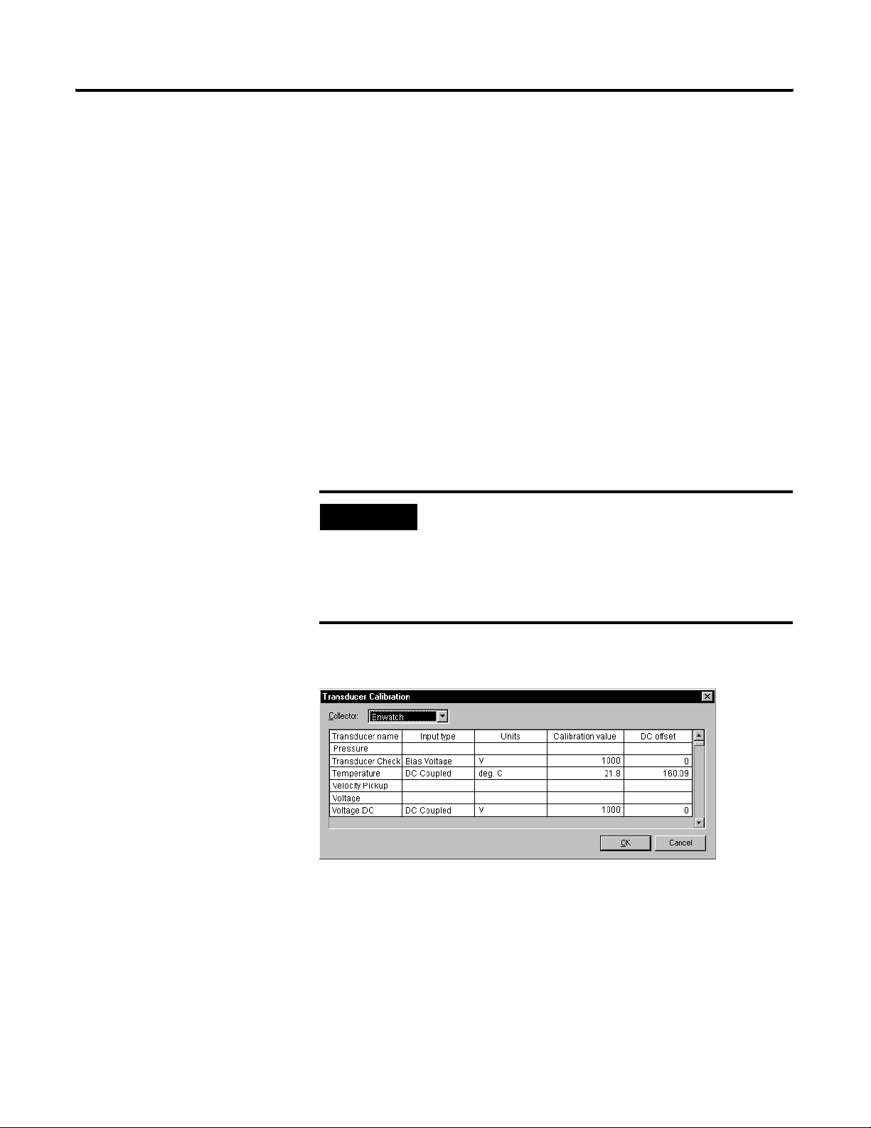
EXAMPLE
In Emonitor, select Setup>Calibration and set up the calibration for the
Temperature transducer.
Input range: (-1.31 V, +0.87 V)
Scale value: (100° F, 200° F)
Calibration: [(0.87 - (-1.31)) x 1000] / (200 - 100) = 21.8
Offset: 100 - (200 - 100) x (-1.31) / (0.87-(-1.31)) = 160.09
Input type should be DC coupled and the jumper setting
on board needs to be set as DC couple as well.
Publication GMSI10-UM031C-EN-E - January 2009
Page 30

26 Installing the Enwatch
Then select Setup>Transducer to select the “Temperature” transducer in the
collection specification.
In Emonitor, define a numeric measurement definition with the temperature
units and the “Temperature” collection specification.
Transducer bias reading
Enwatch can take transducer bias readings; however, this is not a transducer
check function that detects transducer failure before taking data. The bias
reading is an independent reading with a different signal path on the Enwatch
board.
First in Emonitor, select Setup>Transducer to define a new transducer
name, for example, “Transducer Check.”
Publication GMSI10-UM031C-EN-E - January 2009
Page 31

Installing the Enwatch 27
Then select Setup>Calibration to select “Bias Voltage” as the input type for
this transducer. The calibration should set to 1000 and the offset to 0.
Then select Setup>Collection to define a new collection specification. Select
“Transducer Check” as the transducer.
In Emonitor, define a numeric measurement definition with Vdc units and the
“Transducer Bias” collection specification.
Publication GMSI10-UM031C-EN-E - January 2009
Page 32

28 Installing the Enwatch
Saving the machine speed with a spectrum
In the Hardware Setup program, when adding or editing an Enwatch unit,
click the Trigger Channel tab.
The Timeout is defined in seconds (the default is 5 seconds). The Number of
pulse per rev default is 1 pulse per revolution. Click the Channel tab and
assign the correct Trigger channel to the vibration channel. This example
uses trigger channel 1 for the measurement on input channel 1.
Publication GMSI10-UM031C-EN-E - January 2009
When the Enwatch unit collects data for channel 1, the unit checks trigger
channel 1 to get the machine speed reading. The speed reading comes back
with time waveform data and gets stored into the database with the vibration
data.
Page 33

Installing the Enwatch 29
Magnitude and phase reading
A magnitude/phase reading is similar to any other data collector in Emonitor.
You set up an overall measurement, using the “Mag & Phase” collection
specification. Then select “1st Order” as the measurement filter (or any other
desired order).
Validating Enwatch measurements
In the Hardware Setup program, when adding or editing an Enwatch unit, you
can set up a validation function to allow the driver to check the channel’s data
before updating the database. This function can be used to filter unwanted
data when the machine is not running, or when some other parameter is not
within the correct bounds.
Click the Channel tab, then double-click in the Val id ate column to set up the
validation parameters.
Publication GMSI10-UM031C-EN-E - January 2009
Page 34

30 Installing the Enwatch
You can reference any channel and there is no order you need to follow.
Order normalized measurements
You enable order normalized measurements in the collection specification. In
Emonitor, select Setup>Collection. Then either edit an existing collection
specification or create a new one. Make sure the Order normalization
checkbox is selected. The Enwatch unit then finds the machine speed and
Publication GMSI10-UM031C-EN-E - January 2009
Page 35

Installing the Enwatch 31
applies it to the number of orders to select the proper sampling rate before
collecting data.
IMPORTANT
You must also define a trigger channel for the Enwatch
channel so that the Enwatch unit can find the machine
speed.
How are DSP functions handled in the Enwatch driver?
The Enwatch unit only takes time domain data and returns that data to the
host software. All DSP functions are done by the host driver. In this way, the
firmware can focus on data collection speed. Since Enwatch does not handle
calculating the average time waveform, the host driver software must tell the
Enwatch unit to collect a time waveform of sufficient length in order to
calculate the average.
Publication GMSI10-UM031C-EN-E - January 2009
Page 36

32 Installing the Enwatch
Limitation on number of points in Enwatch
The Enwatch unit has 640 K bytes memory for data storage. If you attempt to
collect data on more points than can fit in memory, the unit returns an error
message. The message appears in the Unload Station Manager window (refer
to the Online Applications Guide for more on the Unload Station Manager). The
Enwatch driver can combine measurements in some cases (see “Combining
measurements in the Enwatch driver” on page 21).
If a route has 5 points per channel and 400 lines, 4 averages, no overlap
averaging:
Bytes required: 5 points x 16 channels x 1024 bin x 2 byte/bin x 4 averages =
655360 bytes
If a route has 2 points per channel and 800 lines, 4 averages, no overlap
averaging:
Bytes required: 2 points x 16 channels x 2048 bin x 2 byte/bin x 4 averages =
524288 bytes
Configuration of Emonitor with Enwatch
To best use the 640K memory, try to use overlap averaging. For examples, see
“Maximum number of averages that can be supported” on page 24.
The Enwatch unit is specially designed to operate over an Ethernet
connection. Each Enwatch unit has a unique IP address that can be changed
through the RS232 port inside the unit. Ideally, one Enwatch unload station
can serve an unlimited number of Enwatch units. However, to improve unload
speed, multiple Enwatch unload stations are suggested.
Each Enwatch unit has 16 vibration channels and 4 tachometer channels. In
addition, the Allen Bradley Enlive software (live mode analysis) can be used to
“lock onto” one channel at a time. During live mode analysis, regularly
scheduled unload continues to unload whatever data is in the Enwatch unit
buffers before entering live mode analysis. The Enlive software has a default
timeout of 30 minutes to prevent an extended break in unloading scheduled
data.
For more information on setting up an Enwatch unit in an Emonitor system,
refer to the Online Applications Guide provided with your Emonitor online
system.
Publication GMSI10-UM031C-EN-E - January 2009
Page 37

Chapter
Specifications
This chapter lists the technical specifications for the Enwatch unit.
Enwatch Technical Specifications
Product Feature Specification
Inputs
Number of Channels
16 vibration and 4 tachometer
(synchronizer)
2
Voltage Protection
Input Impedance
Ranges
ICP Interface
Coupling
PGA Gains
Anti-Alias Filter
High Pass Filters
Channel Cross-Talk
Protects against over-voltage (channel
auto-switch off)
2000 V ESD protection
1 MOhm
±10 mV to ±10 V, 7 ranges (software
selectable)
3.6 mA @ 24 VDC, configurable per channel
AC/DC (numeric measurements),
configurable per channel
DC offset removal by optional use of
channel 16
Specified in Chapter 1
Compound analog filter with roll-off better
than 20th order filter; cut-off frequency
related to sample rate.
4th order with corner frequencies 0.36,
2.67, 5.3, and 23.8 Hz
-80 dB
Amplitude Accuracy
Phase Accuracy
Harmonic Distortions
Integration
Acquisition Modes
33 Publication GMSI10-UM031C-EN-E - July 2009
±2% typical in pass-band
±3%
-70 dB (typical)
One 2-stage with ideal stop-band edge at
0.36 Hz
Mode 1: Timed pickup
Mode 2: Data Ready flag
Mode 3: Data broadcast
Page 38

34 Specifications
Enwatch Technical Specifications
Product Feature Specification
Spike Energy Measurement
gSE Filters High pass at 200 Hz & 5 kHz 2nd order
Trigger
TTL Isolated or Non-Isolated, or any voltage
Types
up to +24 V
Maximum combined current for all
channels, not to exceed 100mA
Processing
Outputs
Machine Speed Range
Time to Lock
Averaging
Tachometer Information
Trigger Delays
Time Domain ADC
Sampling Rate
Dynamic Range
Block Lengths
Overall Units
Status
1 to 60,000 RPM
2 revolutions
1, 2, 4, ... 32,000 averages, programmable
RPM using trigger input
Post-trigger delays up to 32,768 samples
Pre-trigger delays up to 16,384 samples
(not used with Emonitor)
16 bit
64 Hz to 51.2 kHz
96 dB (theoretical)
256, 512, 1024, 2048, 4096, or 8192 with
averaging
up to 16,384 without averaging
Acceleration, velocity, or displacement
(double integration in one level hardware &
one level software), and Spike Energy data
LEDs indicate system functions
Publication GMSI10-UM031C-EN-E - July 2009
Storage
Mechanical
Environmental
Power
Interface Port
Memory Buffer
Power Fail Handling
Protection NEMA 4, IP66
Temperature -20 to 70° C
Power Supply
Power Consumption
RS-232C, 9600 baud for diagnostics
640 Kilobytes
Hardware checks for node power and
isolates node with no power
85 to 260 VAC
12 W maximum to board, using 3.6 mA ICP
current sources
Page 39

Enwatch Technical Specifications
Product Feature Specification
Communications
Network
Ethernet
Specifications 35
Medium
Connectors
Speed
Isolation
10BASE-T
Weidmuller terminal blocks
10 Mbits/sec
1000 Vrms
Publication GMSI10-UM031C-EN-E - July 2009
Page 40

36 Specifications
Publication GMSI10-UM031C-EN-E - July 2009
Page 41

Index
Numerics
10 Base T 3, 15
A
AC coupling 7
ADC 3
address
Enwatch IP
HOST IP 13
HOST MAC 12
HOST UDP 13
IP network 11
analog inputs
1–16
AC coupling 7
DC coupling 7
DC voltage signal 19
ICP transducer 7, 17
jumpers 7
velocity sensor 18
analog-to-digital converter 3
anti-aliasing filter 2, 22, 33
11
5
B
Base 3
bias, transducer 2, 23
block diagram 1
block diagram component description 2
board diagram 4
C
clock generator 3
CMOS/TTL 7
coil-based velocity sensor
See velocity sensor
collection specification
configuration with Emonitor 32
26, 27, 29, 30
configuring Enwatch 11
connections
DC voltage signal
Ethernet 6
Hall effect sensor 20
ICP transducer 17
serial port 7
supply voltage 7
velocity sensor 18
connectors
J10
7
J11 10
J1–J11 5
J1–J2 5
J3–J6 6
J8 6
J9 7
19
D
data storage 32
DC coupling 7
DC measurements 25
DC voltage signal
19
jumper
wiring 19
diagrams
block diagram
board 4
DC voltage signal 19
Hall effect sensor 20
ICP transducer wiring 17
velocity sensor wiring 18
DSP functions and Enwatch driver 31
1
E
electrical components 2
electrical connections 4
enclosure 3
Publication GMSI10-UM031C-EN-E - July 2009
Page 42

38 Index
Ethernet
communication LEDs
connection 6
controller/buffer memory 3
external trigger
channels 1–4
CMOS/TTL 7
isolation 9
jumpers 9
wiring 20
6
F
filters
1st order
anti-aliasing 2, 22, 33
gSE 34
high pass 2, 21, 33
settling time 22
Smart HP filter 21
firmware 11
flash memory 11
29
G
gain amplifier 3
gSE filter 34
gSE function 2
8
J
J10 7
J11 10
J11 serial port (RS-232) 7
J1–J11 5
J1–J2 analog inputs 5
J3–J6 external trigger 6
J8 Ethernet connection 6
J9 supply voltage 7
JP17–JP20 9
JP21 9, 11
jumpers
analog inputs
DC voltage signal 19
external trigger 9
ICP transducer 17
JP17–JP20 9
JP21 9, 11
on-board monitor program 9, 11
velocity sensor 18
7
L
LEDs
See light emitting diodes
light emitting diodes
limitations on number of points 32
8
H
Hall effect sensor wiring 20
high pass filter 21, 33
high pass filters 2
HOST IP address 13
HOST MAC address 12
HOST UDP address 13
I
ICP interface 2
ICP transducer
jumper
17
wiring 17
installation 11
installation overview 2
integrator 2
introduction 1
IP network addresses 11
isolating external trigger 9
M
machine speed measurements 28
magnitude and phase measurements 29
measurement capabilities 21
mechanical components 3
memory limitations 32
microprocessor subsystem 3
multiplexer 2
N
network option, assigning 15
O
on-board monitor program
configuring Enwatch
jumpers 9, 11
starting 11
order normalized measurements 30
11
Publication GMSI10-UM031C-EN-E - July 2009
Page 43

Index 39
P
ping 16
power regulation 3
process measurements 25
process signal
See DC voltage signal
R
RS-232 port 7, 10
S
serial port 7, 10
Smart HP filter 21
specifications, measurement 21
specifications, technical 33
Spike Energy function 2
storage, data 32
supply voltage 7, 10
T
tachometer input
See external trigger
technical specifications
temperature measurements 25
33
terminal program 11
transducer bias 2
transducer bias measurements 23, 26
TTL 7
U
U20 11
U28 11
V
validating measurements 29
velocity sensor
jumper
18
wiring 18
W
watchdog 3
wiring
DC voltage signal
external trigger 20
Hall effect sensor 20
ICP transducer 17
velocity sensor 18
19
Publication GMSI10-UM031C-EN-E - July 2009
Page 44

Power Ratings
120mA minimum, 280mA maximum / 24Vdc
Temperature Ratings
-10C to +70C
Publication GMSI10-UM031C-EN-E - July 2009 40 Part Number 44887-PUB
Supersedes Publication 44887 Rev. 2 - January 20 09 Copyright © 2009 Rockwell Automation, In c. All rights reserved. Printed in the U.S.A.
 Loading...