

Page 1
R
SafeZone Mini
Safety Laser Scanner
User Manual
Page 2
Important User Information
Because of the variety of uses for the products described in this publication, those responsible for the
application and use of this control equipment must satisfy themselves that all necessary steps have been
taken to assure that each application and use meets all performance and safety requirements, including
any applicable laws, regulations, codes and standards.
Reproduction of the contents of this copyrighted publication, in whole or part, without written permission
of Rockwell Automation, is prohibited.
Throughout this manual we use notes to make you aware of safety considerations:
The illustrations, charts, sample programs and layout examples shown in the guide are intended solely for
purposes of example. Since there are many variables and requirements associated with any particular
installation, Rockwell Automation does not assume responsibility or liability (to include intellectual property
liability) for actual use based upon the examples shown in this publication.
Rockwell Automation publication SGI-1.1, Safety Guidelines for the Application, Installation and
Maintenance of Solid-State Control (available from your local Rockwell Automation sales oce), describes
some important dierences between solid-state equipment and electromechanical devices that should be
taken into consideration when applying products such as those described in this publication.
It is recommended that you save this user manual for future use.
Identies information about practices or circumstances that can cause an explosion in
a hazardous environment, which may lead to personal injury or death, property
damage, or economic loss.
Identies information that is critical for successful application and understanding of
the product.
Identies information about practices or circumstances that can lead to personal
injury or death, property damage, or economic loss. Attentions help you identify a
hazard, avoid a hazard, and recognize the consequences.
SHOCK HAZARD
Labels may be on or inside the equipment (for example, drive or motor) to alert people
that dangerous voltage may be present.
BURN HAZARD
Labels may be on or inside the equipment (for example, drive or motor) to alert people
that surfaces may reach dangerous temperatures.
WARNING
IMPORTANT
ATTENTION
Page 3

Contents
Contents
About this document . . . . . . . . . . . . . . . . . . . . . . . . . . . . . . . . . . . . . . . . . . . . . . . . . . . Chapter 1
Function of this document . . . . . . . . . . . . . . . . . . . . . . . . . . . . . . . . . . . . . . . . . . . . . . . . . . . . . . . . . . . . . . . . . . . . . . . . . . . . . . . 4
Target group . . . . . . . . . . . . . . . . . . . . . . . . . . . . . . . . . . . . . . . . . . . . . . . . . . . . . . . . . . . . . . . . . . . . . . . . . . . . . . . . . . . . . . . . . . . 4
Scope . . . . . . . . . . . . . . . . . . . . . . . . . . . . . . . . . . . . . . . . . . . . . . . . . . . . . . . . . . . . . . . . . . . . . . . . . . . . . . . . . . . . . . . . . . . . . . . . . 4
Depth of information . . . . . . . . . . . . . . . . . . . . . . . . . . . . . . . . . . . . . . . . . . . . . . . . . . . . . . . . . . . . . . . . . . . . . . . . . . . . . . . . . . . . 4
Abbreviations used . . . . . . . . . . . . . . . . . . . . . . . . . . . . . . . . . . . . . . . . . . . . . . . . . . . . . . . . . . . . . . . . . . . . . . . . . . . . . . . . . . . . . 4
Symbols used . . . . . . . . . . . . . . . . . . . . . . . . . . . . . . . . . . . . . . . . . . . . . . . . . . . . . . . . . . . . . . . . . . . . . . . . . . . . . . . . . . . . . . . . . . 5
On safety . . . . . . . . . . . . . . . . . . . . . . . . . . . . . . . . . . . . . . . . . . . . . . . . . . . . . . . . . . . . . Chapter 2
Qualified safety personnel . . . . . . . . . . . . . . . . . . . . . . . . . . . . . . . . . . . . . . . . . . . . . . . . . . . . . . . . . . . . . . . . . . . . . . . . . . . . . . . 6
Applications of the device . . . . . . . . . . . . . . . . . . . . . . . . . . . . . . . . . . . . . . . . . . . . . . . . . . . . . . . . . . . . . . . . . . . . . . . . . . . . . . . . 6
Correct use. . . . . . . . . . . . . . . . . . . . . . . . . . . . . . . . . . . . . . . . . . . . . . . . . . . . . . . . . . . . . . . . . . . . . . . . . . . . . . . . . . . . . . . . . . . . . 6
General safety notes and protective measures. . . . . . . . . . . . . . . . . . . . . . . . . . . . . . . . . . . . . . . . . . . . . . . . . . . . . . . . . . . . . . . 7
Environmental protection . . . . . . . . . . . . . . . . . . . . . . . . . . . . . . . . . . . . . . . . . . . . . . . . . . . . . . . . . . . . . . . . . . . . . . . . . . . . . . . . 7
Disposal . . . . . . . . . . . . . . . . . . . . . . . . . . . . . . . . . . . . . . . . . . . . . . . . . . . . . . . . . . . . . . . . . . . . . . . . . . . . . . . . . . . . . . . . . . 8
Separation of materials . . . . . . . . . . . . . . . . . . . . . . . . . . . . . . . . . . . . . . . . . . . . . . . . . . . . . . . . . . . . . . . . . . . . . . . . . . . . . 8
Applicable directives and standards . . . . . . . . . . . . . . . . . . . . . . . . . . . . . . . . . . . . . . . . . . . . . . . . . . . . . . . . . . . . . . . . . . . . . . . 8
Product description . . . . . . . . . . . . . . . . . . . . . . . . . . . . . . . . . . . . . . . . . . . . . . . . . . . . Chapter 3
Special features . . . . . . . . . . . . . . . . . . . . . . . . . . . . . . . . . . . . . . . . . . . . . . . . . . . . . . . . . . . . . . . . . . . . . . . . . . . . . . . . . . . . . . .10
Function. . . . . . . . . . . . . . . . . . . . . . . . . . . . . . . . . . . . . . . . . . . . . . . . . . . . . . . . . . . . . . . . . . . . . . . . . . . . . . . . . . . . . . . . . . . . . .10
Principle of operation . . . . . . . . . . . . . . . . . . . . . . . . . . . . . . . . . . . . . . . . . . . . . . . . . . . . . . . . . . . . . . . . . . . . . . . . . . . . . . 10
Field set comprising of protective field and warning field(s) . . . . . . . . . . . . . . . . . . . . . . . . . . . . . . . . . . . . . . . . . . . . . 11
SafeZone Mini . . . . . . . . . . . . . . . . . . . . . . . . . . . . . . . . . . . . . . . . . . . . . . . . . . . . . . . . . . . . . . . . . . . . . . . . . . . . . . . . . . . . . . . . . 12
Device components. . . . . . . . . . . . . . . . . . . . . . . . . . . . . . . . . . . . . . . . . . . . . . . . . . . . . . . . . . . . . . . . . . . . . . . . . . . . . . . . 12
Applications . . . . . . . . . . . . . . . . . . . . . . . . . . . . . . . . . . . . . . . . . . . . . . . . . . . . . . . . . . . . . . . . . . . . . . . . . . . . . . . . . . . . . . 13
Status indicators. . . . . . . . . . . . . . . . . . . . . . . . . . . . . . . . . . . . . . . . . . . . . . . . . . . . . . . . . . . . . . . . . . . . . . . . . . . . . . . . . . . . . . . 14
LEDs and seven-segment display . . . . . . . . . . . . . . . . . . . . . . . . . . . . . . . . . . . . . . . . . . . . . . . . . . . . . . . . . . . . . . . . . . . . 14
Configurable functions . . . . . . . . . . . . . . . . . . . . . . . . . . . . . . . . . . . . . . . . . . . . . . . . . Chapter 4
System parameters . . . . . . . . . . . . . . . . . . . . . . . . . . . . . . . . . . . . . . . . . . . . . . . . . . . . . . . . . . . . . . . . . . . . . . . . . . . . . . . . . . . . 15
Application name . . . . . . . . . . . . . . . . . . . . . . . . . . . . . . . . . . . . . . . . . . . . . . . . . . . . . . . . . . . . . . . . . . . . . . . . . . . . . . . . . 15
Name of the scanner. . . . . . . . . . . . . . . . . . . . . . . . . . . . . . . . . . . . . . . . . . . . . . . . . . . . . . . . . . . . . . . . . . . . . . . . . . . . . . . 15
User data . . . . . . . . . . . . . . . . . . . . . . . . . . . . . . . . . . . . . . . . . . . . . . . . . . . . . . . . . . . . . . . . . . . . . . . . . . . . . . . . . . . . . . . . 15
Display direction of the seven-segment display . . . . . . . . . . . . . . . . . . . . . . . . . . . . . . . . . . . . . . . . . . . . . . . . . . . . . . . . 15
Application . . . . . . . . . . . . . . . . . . . . . . . . . . . . . . . . . . . . . . . . . . . . . . . . . . . . . . . . . . . . . . . . . . . . . . . . . . . . . . . . . . . . . . . . . . .16
Resolution . . . . . . . . . . . . . . . . . . . . . . . . . . . . . . . . . . . . . . . . . . . . . . . . . . . . . . . . . . . . . . . . . . . . . . . . . . . . . . . . . . . . . . . 16
Basic response time . . . . . . . . . . . . . . . . . . . . . . . . . . . . . . . . . . . . . . . . . . . . . . . . . . . . . . . . . . . . . . . . . . . . . . . . . . . . . . . 16
Maximum protective field range. . . . . . . . . . . . . . . . . . . . . . . . . . . . . . . . . . . . . . . . . . . . . . . . . . . . . . . . . . . . . . . . . . . . . 16
Universal I/O connections of the SafeZone Mini. . . . . . . . . . . . . . . . . . . . . . . . . . . . . . . . . . . . . . . . . . . . . . . . . . . . . . . . . . . . . 17
OSSDs. . . . . . . . . . . . . . . . . . . . . . . . . . . . . . . . . . . . . . . . . . . . . . . . . . . . . . . . . . . . . . . . . . . . . . . . . . . . . . . . . . . . . . . . . . . . . . . . 18
Internal OSSDs of the SafeZone Mini . . . . . . . . . . . . . . . . . . . . . . . . . . . . . . . . . . . . . . . . . . . . . . . . . . . . . . . . . . . . . . . . . 18
External device monitoring (EDM) SafeZone Mini . . . . . . . . . . . . . . . . . . . . . . . . . . . . . . . . . . . . . . . . . . . . . . . . . . . . . . 18
Restart of the SafeZone Mini. . . . . . . . . . . . . . . . . . . . . . . . . . . . . . . . . . . . . . . . . . . . . . . . . . . . . . . . . . . . . . . . . . . . . . . . . . . . . 18
Field sets . . . . . . . . . . . . . . . . . . . . . . . . . . . . . . . . . . . . . . . . . . . . . . . . . . . . . . . . . . . . . . . . . . . . . . . . . . . . . . . . . . . . . . . . . . . . . 20
Configuring the protective field and warning field . . . . . . . . . . . . . . . . . . . . . . . . . . . . . . . . . . . . . . . . . . . . . . . . . . . . . 20
Protective field or warning field suggested by the safety laser scanner . . . . . . . . . . . . . . . . . . . . . . . . . . . . . . . . . . . . 21
Using the contour as a reference. . . . . . . . . . . . . . . . . . . . . . . . . . . . . . . . . . . . . . . . . . . . . . . . . . . . . . . . . . . . . . . . . . . . . 21
Monitoring cases . . . . . . . . . . . . . . . . . . . . . . . . . . . . . . . . . . . . . . . . . . . . . . . . . . . . . . . . . . . . . . . . . . . . . . . . . . . . . . . . . . . . . . 22
Multiple sampling. . . . . . . . . . . . . . . . . . . . . . . . . . . . . . . . . . . . . . . . . . . . . . . . . . . . . . . . . . . . . . . . . . . . . . . . . . . . . . . . . 23
Stand-by mode . . . . . . . . . . . . . . . . . . . . . . . . . . . . . . . . . . . . . . . . . . . . . . . . . . . . . . . . . . . . . . . . . . . . . . . . . . . . . . . . . . . 23
Mounting. . . . . . . . . . . . . . . . . . . . . . . . . . . . . . . . . . . . . . . . . . . . . . . . . . . . . . . . . . . . . Chapter 5
Stationary application in horizontal operation . . . . . . . . . . . . . . . . . . . . . . . . . . . . . . . . . . . . . . . . . . . . . . . . . . . . . . . . . . . . . 24
Protective field size. . . . . . . . . . . . . . . . . . . . . . . . . . . . . . . . . . . . . . . . . . . . . . . . . . . . . . . . . . . . . . . . . . . . . . . . . . . . . . . . 25
Stationary vertical operaton for access protection. . . . . . . . . . . . . . . . . . . . . . . . . . . . . . . . . . . . . . . . . . . . . . . . . . . . . . . . . . . 27
Minimum distance . . . . . . . . . . . . . . . . . . . . . . . . . . . . . . . . . . . . . . . . . . . . . . . . . . . . . . . . . . . . . . . . . . . . . . . . . . . . . . . . 27
Stationary vertical operation for hazardous point protection . . . . . . . . . . . . . . . . . . . . . . . . . . . . . . . . . . . . . . . . . . . . . . . . . 29
Rockwell Automation Publication 10000337275 Ver 01—October 2014 1
Page 4

Contents
Minimum distance . . . . . . . . . . . . . . . . . . . . . . . . . . . . . . . . . . . . . . . . . . . . . . . . . . . . . . . . . . . . . . . . . . . . . . . . . . . . . . . . 29
Mobile applications . . . . . . . . . . . . . . . . . . . . . . . . . . . . . . . . . . . . . . . . . . . . . . . . . . . . . . . . . . . . . . . . . . . . . . . . . . . . . . . . . . . . 30
Mounting (continued) . . . . . . . . . . . . . . . . . . . . . . . . . . . . . . . . . . . . . . . . . . . . . . . . . . Chapter 5
Protective field length . . . . . . . . . . . . . . . . . . . . . . . . . . . . . . . . . . . . . . . . . . . . . . . . . . . . . . . . . . . . . . . . . . . . . . . . . . . . . 30
Protective field width . . . . . . . . . . . . . . . . . . . . . . . . . . . . . . . . . . . . . . . . . . . . . . . . . . . . . . . . . . . . . . . . . . . . . . . . . . . . . . 32
Height of the scan plane . . . . . . . . . . . . . . . . . . . . . . . . . . . . . . . . . . . . . . . . . . . . . . . . . . . . . . . . . . . . . . . . . . . . . . . . . . . 33
Methods of preventing unprotected areas . . . . . . . . . . . . . . . . . . . . . . . . . . . . . . . . . . . . . . . . . . . . . . . . . . . . . . . . . . . . . . . . . 33
Near range . . . . . . . . . . . . . . . . . . . . . . . . . . . . . . . . . . . . . . . . . . . . . . . . . . . . . . . . . . . . . . . . . . . . . . . . . . . . . . . . . . . . . . . 35
Mounting steps. . . . . . . . . . . . . . . . . . . . . . . . . . . . . . . . . . . . . . . . . . . . . . . . . . . . . . . . . . . . . . . . . . . . . . . . . . . . . . . . . . . . . . . . 35
Direct mounting . . . . . . . . . . . . . . . . . . . . . . . . . . . . . . . . . . . . . . . . . . . . . . . . . . . . . . . . . . . . . . . . . . . . . . . . . . . . . . . . . .36
Mounting with mounting kit 1a or 1b . . . . . . . . . . . . . . . . . . . . . . . . . . . . . . . . . . . . . . . . . . . . . . . . . . . . . . . . . . . . . . . . 36
Mounting with mounting kit 2 and 3. . . . . . . . . . . . . . . . . . . . . . . . . . . . . . . . . . . . . . . . . . . . . . . . . . . . . . . . . . . . . . . . . 36
Information label Important information . . . . . . . . . . . . . . . . . . . . . . . . . . . . . . . . . . . . . . . . . . . . . . . . . . . . . . . . . . . . . 37
Using multiple SafeZone Mini safet y laser scanners. . . . . . . . . . . . . . . . . . . . . . . . . . . . . . . . . . . . . . . . . . . . . . . . . . . . . 37
Electrical installation. . . . . . . . . . . . . . . . . . . . . . . . . . . . . . . . . . . . . . . . . . . . . . . . . . . Chapter 6
System connection. . . . . . . . . . . . . . . . . . . . . . . . . . . . . . . . . . . . . . . . . . . . . . . . . . . . . . . . . . . . . . . . . . . . . . . . . . . . . . . . . . . . .40
Round plug connector SafeZone Mini. . . . . . . . . . . . . . . . . . . . . . . . . . . . . . . . . . . . . . . . . . . . . . . . . . . . . . . . . . . . . . . . . 40
Configuration connection M8 × 4 (serial interface). . . . . . . . . . . . . . . . . . . . . . . . . . . . . . . . . . . . . . . . . . . . . . . . . . . . . . . . . 41
Application examples and connection diagrams. . . . . . . . . . . . . . . . . . . . . . . . . . . . Chapter 7
Stationary applications . . . . . . . . . . . . . . . . . . . . . . . . . . . . . . . . . . . . . . . . . . . . . . . . . . . . . . . . . . . . . . . . . . . . . . . . . . . . . . . . . 42
Applications with one monitored area (SafeZone Mini) . . . . . . . . . . . . . . . . . . . . . . . . . . . . . . . . . . . . . . . . . . . . . . . . . 42
Mobile applications . . . . . . . . . . . . . . . . . . . . . . . . . . . . . . . . . . . . . . . . . . . . . . . . . . . . . . . . . . . . . . . . . . . . . . . . . . . . . . . . . . . . 43
Vehicle monitoring for unidirectional travel (SafeZone Mini) . . . . . . . . . . . . . . . . . . . . . . . . . . . . . . . . . . . . . . . . . . . . . 43
Connection diagrams. . . . . . . . . . . . . . . . . . . . . . . . . . . . . . . . . . . . . . . . . . . . . . . . . . . . . . . . . . . . . . . . . . . . . . . . . . . . . . . . . . . 43
SafeZone Mini with restart interlock and external device monitoring. . . . . . . . . . . . . . . . . . . . . . . . . . . . . . . . . . . . . . 44
SafeZone Mini in combination with a UE10 safety relay . . . . . . . . . . . . . . . . . . . . . . . . . . . . . . . . . . . . . . . . . . . . . . . . . 44
Protective field switching using a Flexi Classic safety controller. . . . . . . . . . . . . . . . . . . . . . . . . . . . . . . . . . . . . . . . . . . 45
Configuration . . . . . . . . . . . . . . . . . . . . . . . . . . . . . . . . . . . . . . . . . . . . . . . . . . . . . . . . . Chapter 8
Default delivery status. . . . . . . . . . . . . . . . . . . . . . . . . . . . . . . . . . . . . . . . . . . . . . . . . . . . . . . . . . . . . . . . . . . . . . . . . . . . . . . . . . 46
Preparation of the configuration . . . . . . . . . . . . . . . . . . . . . . . . . . . . . . . . . . . . . . . . . . . . . . . . . . . . . . . . . . . . . . . . . . . . . . . . . 46
Commissioning . . . . . . . . . . . . . . . . . . . . . . . . . . . . . . . . . . . . . . . . . . . . . . . . . . . . . . . . Chapter 9
Initial commissioning . . . . . . . . . . . . . . . . . . . . . . . . . . . . . . . . . . . . . . . . . . . . . . . . . . . . . . . . . . . . . . . . . . . . . . . . . . . . . . . . . . 47
Power-up sequence . . . . . . . . . . . . . . . . . . . . . . . . . . . . . . . . . . . . . . . . . . . . . . . . . . . . . . . . . . . . . . . . . . . . . . . . . . . . . . . 47
Test notes . . . . . . . . . . . . . . . . . . . . . . . . . . . . . . . . . . . . . . . . . . . . . . . . . . . . . . . . . . . . . . . . . . . . . . . . . . . . . . . . . . . . . . . . . . . . 47
Pre-commissioning tests . . . . . . . . . . . . . . . . . . . . . . . . . . . . . . . . . . . . . . . . . . . . . . . . . . . . . . . . . . . . . . . . . . . . . . . . . . . 47
Regular inspection of the protective device by qualified safety personnel . . . . . . . . . . . . . . . . . . . . . . . . . . . . . . . . . . 48
Daily testing of the protective device by a specialist or authorized personnel . . . . . . . . . . . . . . . . . . . . . . . . . . . . . . . 48
Maintenance and care. . . . . . . . . . . . . . . . . . . . . . . . . . . . . . . . . . . . . . . . . . . . . . . . .Chapter 10
Cleaning optics cover . . . . . . . . . . . . . . . . . . . . . . . . . . . . . . . . . . . . . . . . . . . . . . . . . . . . . . . . . . . . . . . . . . . . . . . . . . . . . . . . . . . 49
Replacing the optics cover . . . . . . . . . . . . . . . . . . . . . . . . . . . . . . . . . . . . . . . . . . . . . . . . . . . . . . . . . . . . . . . . . . . . . . . . . . . . . . 49
Diagnostics . . . . . . . . . . . . . . . . . . . . . . . . . . . . . . . . . . . . . . . . . . . . . . . . . . . . . . . . . . Chapter 11
In the event of faults or errors . . . . . . . . . . . . . . . . . . . . . . . . . . . . . . . . . . . . . . . . . . . . . . . . . . . . . . . . . . . . . . . . . . . . . . . . . . . 51
Rockwell Automation support . . . . . . . . . . . . . . . . . . . . . . . . . . . . . . . . . . . . . . . . . . . . . . . . . . . . . . . . . . . . . . . . . . . . . . . . . . . 51
Error and status indications on the LEDs . . . . . . . . . . . . . . . . . . . . . . . . . . . . . . . . . . . . . . . . . . . . . . . . . . . . . . . . . . . . . . . . . . . 52
Error and status indications on the seven-segment display . . . . . . . . . . . . . . . . . . . . . . . . . . . . . . . . . . . . . . . . . . . . . . . . . . . 52
The lock-out operational status . . . . . . . . . . . . . . . . . . . . . . . . . . . . . . . . . . . . . . . . . . . . . . . . . . . . . . . . . . . . . . . . . . . . . 54
Extended diagnostics. . . . . . . . . . . . . . . . . . . . . . . . . . . . . . . . . . . . . . . . . . . . . . . . . . . . . . . . . . . . . . . . . . . . . . . . . . . . . . . . . . . 54
Technical specifications. . . . . . . . . . . . . . . . . . . . . . . . . . . . . . . . . . . . . . . . . . . . . . . . Chapter 12
OSSD response times . . . . . . . . . . . . . . . . . . . . . . . . . . . . . . . . . . . . . . . . . . . . . . . . . . . . . . . . . . . . . . . . . . . . . . . . . . . . . . . . . . . 55
Timing behavior of the OSSDs of the SafeZone Mini . . . . . . . . . . . . . . . . . . . . . . . . . . . . . . . . . . . . . . . . . . . . . . . . . . . . . . . . . 56
Data sheet . . . . . . . . . . . . . . . . . . . . . . . . . . . . . . . . . . . . . . . . . . . . . . . . . . . . . . . . . . . . . . . . . . . . . . . . . . . . . . . . . . . . . . . . . . . . 58
Dimensional drawings. . . . . . . . . . . . . . . . . . . . . . . . . . . . . . . . . . . . . . . . . . . . . . . . . . . . . . . . . . . . . . . . . . . . . . . . . . . . . . . . . . 61
2 Rockwell Automation Publication 10000337275 Ver 01—October 2014
Page 5

Contents
SafeZone Mini . . . . . . . . . . . . . . . . . . . . . . . . . . . . . . . . . . . . . . . . . . . . . . . . . . . . . . . . . . . . . . . . . . . . . . . . . . . . . . . . . . . . 61
Mounting kits . . . . . . . . . . . . . . . . . . . . . . . . . . . . . . . . . . . . . . . . . . . . . . . . . . . . . . . . . . . . . . . . . . . . . . . . . . . . . . . . . . . . 62
Scan plane origin. . . . . . . . . . . . . . . . . . . . . . . . . . . . . . . . . . . . . . . . . . . . . . . . . . . . . . . . . . . . . . . . . . . . . . . . . . . . . . . . . . 64
Ordering information . . . . . . . . . . . . . . . . . . . . . . . . . . . . . . . . . . . . . . . . . . . . . . . . . Chapter 13
Items supplied SafeZone Mini . . . . . . . . . . . . . . . . . . . . . . . . . . . . . . . . . . . . . . . . . . . . . . . . . . . . . . . . . . . . . . . . . . . . . . . . . . . 65
Accessories/spare parts . . . . . . . . . . . . . . . . . . . . . . . . . . . . . . . . . . . . . . . . . . . . . . . . . . . . . . . . . . . . . . . . . . . . . . . . . . . . . . . . . 65
Mounting kits . . . . . . . . . . . . . . . . . . . . . . . . . . . . . . . . . . . . . . . . . . . . . . . . . . . . . . . . . . . . . . . . . . . . . . . . . . . . . . . . . . . . 65
Annex. . . . . . . . . . . . . . . . . . . . . . . . . . . . . . . . . . . . . . . . . . . . . . . . . . . . . . . . . . . . . . . Chapter 14
EC declaration of conformity. . . . . . . . . . . . . . . . . . . . . . . . . . . . . . . . . . . . . . . . . . . . . . . . . . . . . . . . . . . . . . . . . . . . . . . . . . . . . 68
Checklist for the manufacturer . . . . . . . . . . . . . . . . . . . . . . . . . . . . . . . . . . . . . . . . . . . . . . . . . . . . . . . . . . . . . . . . . . . . . . . . . . . 70
Glossary . . . . . . . . . . . . . . . . . . . . . . . . . . . . . . . . . . . . . . . . . . . . . . . . . . . . . . . . . . . . . . . . . . . . . . . . . . . . . . . . . . . . . . . . . . . . . . 71
List of tables . . . . . . . . . . . . . . . . . . . . . . . . . . . . . . . . . . . . . . . . . . . . . . . . . . . . . . . . . . . . . . . . . . . . . . . . . . . . . . . . . . . . . . . . . . 72
List of illustrations . . . . . . . . . . . . . . . . . . . . . . . . . . . . . . . . . . . . . . . . . . . . . . . . . . . . . . . . . . . . . . . . . . . . . . . . . . . . . . . . . . . . . 73
Rockwell Automation Publication 10000337275 Ver 01—October 2014 3
Page 6

Chapter 1 About this document
Chapter 1
About this document
Please read this chapter carefully before working with this documentation and the SafeZone Mini.
Function of this document
Target group
Scope
Depth of information
These operating instructions are designed to address the technical personnel of the machine manufacturer or the machine
operator in regards to correct mounting, electrical installation, commissioning, operation and maintenance of the
SafeZone Mini safety laser scanner.
These operating instructions do not provide instructions for operating the machine, the system or the vehicle on which the
safety laser scanner is, or will be, integrated. Information on this is to be found in the appropriate operating instructions
for the machine, the system or the vehicle.
These operating instructions are addressed to planning engineers, machine designers and the operators of machines and
systems which are to be protected by one or several SafeZone Mini safety laser scanners. They also address people who
integrate the SafeZone Mini into a machine, a system or a vehicle, initialize its use, or who are in charge of servicing and
maintaining the device.
These operating instructions are original operating instructions.
These operating instructions are only applicable to the SafeZone Mini safety laser scanner with the following entry on the
type label in the field Operating Instructions (Pub. No. 10000337275).
For the configuration and diagnostics of these devices you require the SCD (version 3.0 or higher) programming software.
To determine the software version, select the Module Info… option in the Help menu.
These operating instructions contain information on the SafeZone Mini safety laser scanner. They have the following parts:
• Mounting • Fault diagnosis and troubleshooting
• Electrical installation • Catalog numbers
• Commissioning and configuration • Accessories
• Care and maintenance • Conformity and approval
Planning and using protective devices such as the SafeZone Mini also require specific technical skills which are not detailed
in this documentation.
General information on accident prevention using opto-elect ronic protective devices can be found in the competence
brochure “Guidelines Safe Machinery.”
When operating the SafeZone Mini, the national, local and statutory rules and regulations must be observed.
Please refer also to the Rockwell Automation home page on the Internet at www.rockwellautomation.com.
Note:
Here you will find information on:
• Application examples
• A list of frequently asked questions regarding the SafeZone Mini
• These operating instructions in different languages for viewing and printing
Abbreviations used
Automated Guided Vehicle
AGV
American National Standards Institute
ANSI
American Wire Gauge = standardization and classification of wires and cables by type, diameter etc.
AWG
External device monitoring
EDM
Electromagnetic compatibility
EMC
4 Rockwell Automation Publication 10000337275 Ver 01—October 2014
Page 7
Chapter 1 About this document
.
.
Electrostatic discharge
ESD
Electro-sensitive protective equipment
ESPE
Fail-safe programmable logic controller
FPLC
Output signal switching device = signal output of the protective device that is used to stop the dangerous movement
OSSD
Robotic Industries Association
RIA
Symbols used
SCD software
Recommendation
Note
.
.
,
,
Take actio n…
Warning!
Rockwell Automation Safety Configuration and Diagnostic Software (SCD software) = software for configuration and
diagnostics on the SafeZone Mini
Recommendations are designed to give you some assistance in your decision-making process with respect to a certain
function or a technical measure.
Refer to notes for special features of the device.
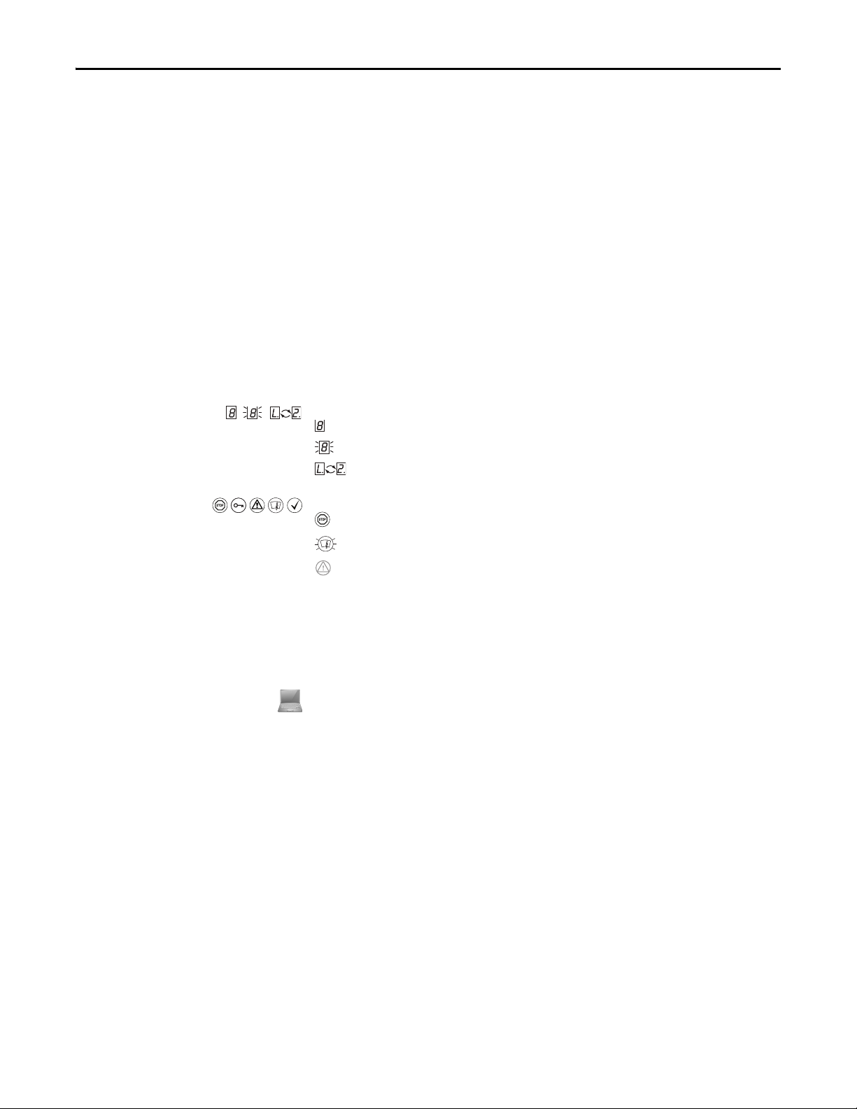
Display indicators show the status of the sevensegment display on the SafeZone Mini:
Constant indication of characters, e.g. 8
Flashing indication of characters, e.g. 8
Alternating indication of characters, e.g. L and 2
LED symbols describe the status of an LED:
The “OSSDs in the OFF state” LED is illuminated continuously.
The “Error/contamination” LED is flashing.
The “Warning field interrupted” LED is off.
Instructions for taking ac tion are shown by an arrow. Read carefully and follow the instructions for action.
A warning indicates an actual or potential risk or health hazard. Observation and implementation of the warning will
protect you from accidents.
Read carefully and follow the warning notices!
Information is displayed in the software indicating to you which settings you can make in the SCD software (Safety
Configuration and Diagnostic Software).
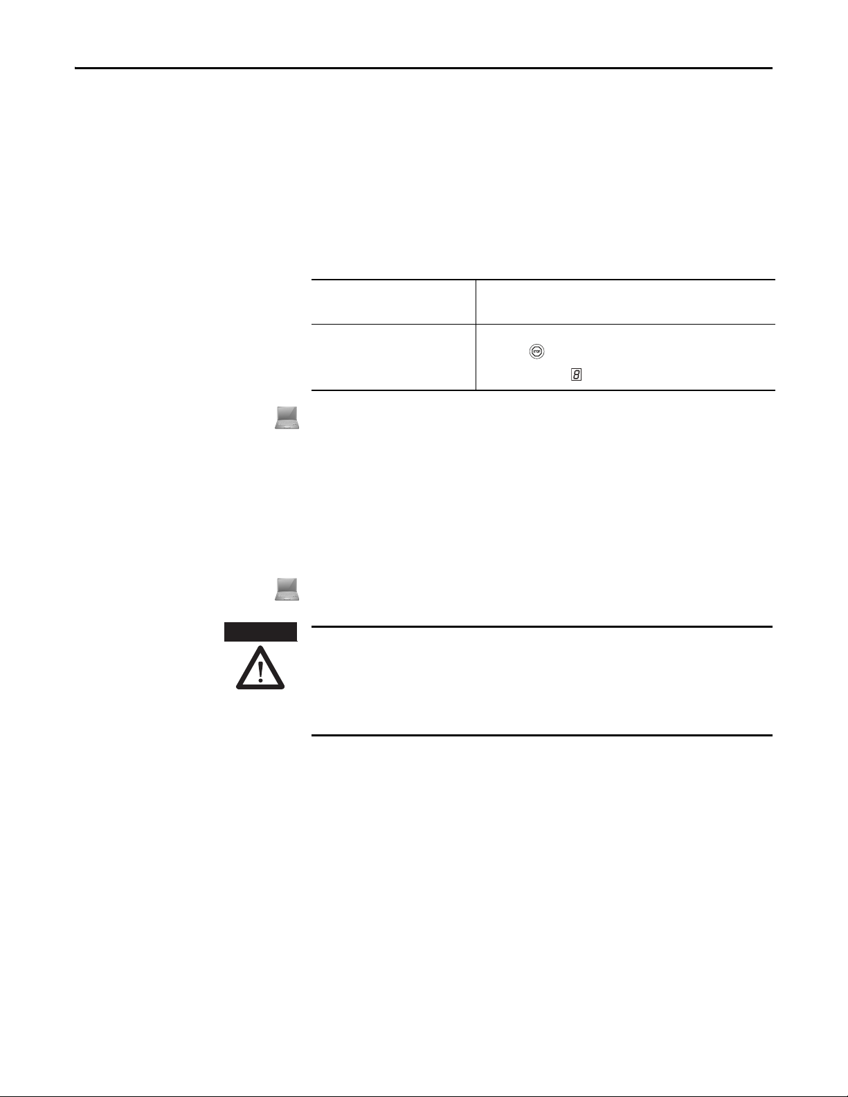
The term “dangerous state”
The dangerous state (standard term) of the machine is always shown in the drawings and diagrams of this document as a
movement of a machine part. In practical operation, there may be a number of different dangerous states:
• Machine movements
• Vehicle movements
• Electrical conductors
• Visible or invisible radiation
• Combination of several risks and hazards
Rockwell Automation Publication 10000337275 Ver 01—October 2014 5
Page 8

Chapter 2 On safety
Chapter 2
On safety
This chapter deals with your own safety and the safety of the system operators.
Please read this chapter carefully before working with the SafeZone Mini or with the machine protected by the
SafeZone Mini.
Qualified safety personnel
Applications of the device
The SafeZone Mini safety laser scanner must be installed, connected, commissioned and serviced only by qualified safety
personnel. Qualified safety personnel are defined as persons who:
• Due to their specialist training and experience have adequate knowledge of the power-driven equipment to be
checked,
• Have been instructed by the responsible machine owner in the operation of the machine and the current valid safety
guidelines,
• Are sufficiently familiar with the applicable official health and safety regulations, directives and generally recognized
engineering practice (e.g. DIN standards, VDE stipulations, engineering regulations from other EC member states) that
they can assess the work safety aspec ts of the power-driven equipment, and
• Have access to these operating instructions and have read them.
As a rule these are qualified safety personnel from the ESPE manufacturer or also those persons who have been
appropriately trained at the ESPE manufacturer, are primarily involved in checking ESPE and are allocated the task by the
organization operating the ESPE.
The SafeZone Mini safety laser scanner is used to protect persons and systems. It is intended to be used to monitor
hazardous areas indoors.
• It is not allowed to use the SafeZone Mini outdoors.
• The SafeZone Mini cannot provide protection from parts thrown out of the machine or emitted radiation.
• The SafeZone Mini complies with the requirements in the standard on the radiated emissions as defined for class A
(industrial application); the SafeZone Mini is therefore only suitable for use in an industrial environment.
• The device is a type 3 ESPE as defined by EN 614961 and CLC/TS 614963 and is therefore allowed for use with
category 3 PL d controls as per EN ISO 138491 or SIL2 as per IEC 61508.
• The SafeZone Mini is suitable for:
– Hazardous area protection
– Hazardous point protection
– Access protection
– Vehicle protection (electrically powered industrial trucks)
Depending on the application, other protective devices and measures may be required in addition to the safety laser
Note
scanner.
Correct use
6 Rockwell Automation Publication 10000337275 Ver 01—October 2014
The SafeZone Mini safety laser scanner must be used only as defined in Chapter 2, “Applications of the device” on page 6. It
must be used only by qualified personnel and only on the machine where it has been installed and initialized by qualified
safety personnel in accordance with these operating instructions. It is only permitted to be used on machines on which the
dangerous state can be stopped immediately by the SafeZone Mini and/or it is possible to prevent the machine being
placed in operation.
If the device is used for any other purposes or modified in any way — also during mounting and installation — any
Note
warranty claim against Rockwell Automation shall become void.
Page 9
General safety notes and
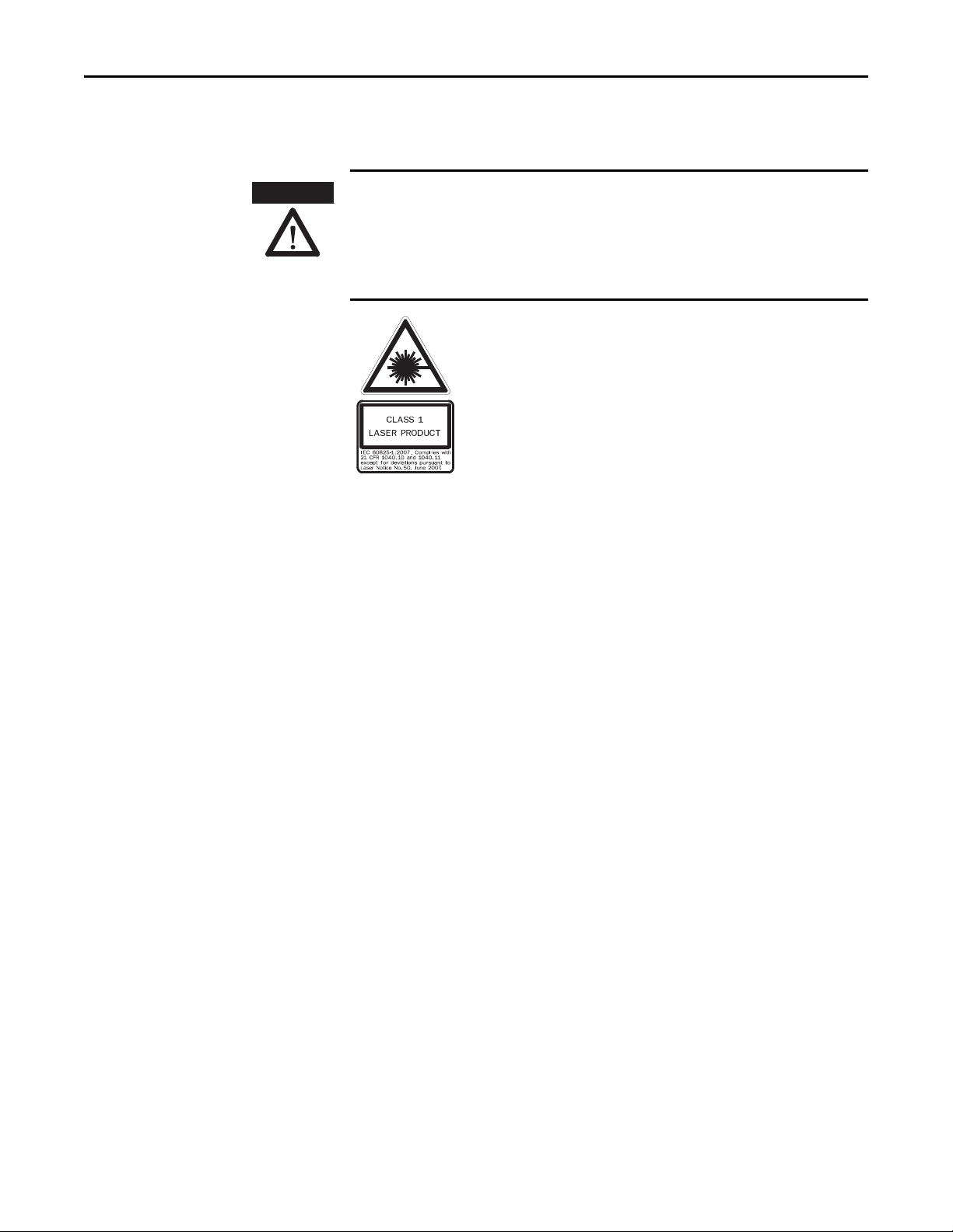
ATTENTION
The SafeZone Mini safety laser scanner is of laser safety class 1. Additional
measures for screening the laser radiation are not necessary (eye safe).
protective measures
Chapter 2 On safety
Pay attention to the safety notes!
Please observe the following items in order to ensure the correct use of the SafeZone Mini safety laser scanner.
Repair only by authorized persons!
The improper repair of the protective device can result in the loss of the protective function. The protective device is only
allowed to be repaired by the manufacturer or persons authorized by the manufacturer.
• This device meets the norms: IEC 608251 as well as CDRH 21 CFR 1040.10 and 1040.11; excluded are deviations due to
Laser Notice No. 50, dated 24.06.2007. In the standards CDRH 21CFR 1040.10 and 1040.11 the following note is
required: “Caution — use of controls, adjustments or performance of procedures other than those herein specified
may result in hazardous radiation exposure!”
• During the mounting, installation and usage of the SafeZone Mini, observe the standards and directives applicable in
your country. You will find an overview of the most important regulations in Chapter 2, “Applicable directives and
standards” on page 8.
• The national/international rules and regulations apply to the installation, commissioning, use and periodic technical
inspections of the SafeZone Mini safety laser scanner, in particular…
– Machinery Directive 2006/42/EC
– Work Equipment Directive 2009/104/EC
– The work safety regulations/safety rules
– Other relevant health and safety regulations
• Manufacturers and operators of the machine on which the SafeZone Mini is used are responsible for obtaining and
observing all applicable safety regulations and rules.
• The notes, in particular the test notes (see Chapter 9, “Commissioning” on page 47) in these operating instructions
(e.g. on use, mounting, installation or integration into the machine control) must be observed.
• Changes to the configuration of the devices can degrade the protective function. After every change to the
configuration you must therefore check the effectiveness of the protective device. The person who makes the change
is also responsible for the correct protective function of the device. When making configuration changes, please
always use the password hierarchy provided by Rockwell Automation to ensure that only authorized persons make
changes to the configuration.
• The tests must be carried out by qualified safety personnel or specially qualified and authorized personnel and must
be recorded and doc umented to ensure that the te sts can be reconstructed and retraced at any time.
• The operating instructions must be made available to the operator of the machine where the SafeZone Mini is used.
The machine operator is to be instructed in the use of the device by qualified safety personnel and must be instructed
to read the operating instructions.
• To meet the requirements of the relevant product standards (e.g. EN 614961), the external voltage supply for the
devices must be able to bridge a brief mains failure of 20 ms. Power supplies according to EN 602041 satisfy this
requirement. Suitable power supplies are available as accessories from Rockwell Automation.
Enclosed with these operating instructions is a checklist for checking by the manufacturer and OEM (see Chapter 14,
“Checklist for the manufacturer” on page 70). Use this checklist when checking the system that is protected with the
SafeZone Mini.
Environmental protection
The SafeZone Mini safety laser scanner is constructed in such a way that it adversely affects the environment as little as
possible and uses only a minimum of power and natural resources.
At work, always act in an environmentally responsible manner.
Rockwell Automation Publication 10000337275 Ver 01—October 2014 7
Page 10
Chapter 2 On safety
ATTENTION
Disposal
Unusable or irreparable devices should always be disposed as per the applicable national regulations on waste disposal
(e.g. European waste code 16 02 14).
• Information on the individual materials in the SafeZone Mini is given in Chapter 12 “Technical specifications” on page
Note
55.
Separation of materials
Only qualified safety personnel are allowed to separate materials!
Caution is required when dismantling devices. There is a risk of injuries.
Before you send the devices for appropriate recycling, it is necessary to separate the different materials in the SafeZone
Mini.
Separate the housing from the rest of the parts (in particular the circuit boards).
Send the separated parts for recycling as appropriate (see Tab. 1).
Table 1: Overview on
disposal by components
Applicable directives and
standards
Components Disposal
Product
Housing Metal recycling (aluminium)
Motor bracket Metal recycling (zinc die-cast housing)
Optics cover Plastic recycling
Circuit boards, cables, connectors and electrical
connecting pieces
Pack aging
Cardboard, paper Paper/cardboard recycling
Polyethylene packaging Plastic recycling
The most important directives and standards, valid for the use of opto-elec tronic protective devices in Europe, are listed
below. Further regulations may be of importance to you, depending on the application. You can obtain further
information of machine-specific standards from national institutions (e.g. DIN, BSI, AFNOR etc.), the authorities or your
trade association.
If you operate the machine or vehicle in a country outside the European Union, please contact the manufacturer of the
system and the local authorities and obtain information on the regulations and standards applicable there.
Electronic recycling
Application and installation of protective devices
Machinery Directive 2006/42/EC, e.g.:
• Safety of machinery — Basic concepts, general principles for design (EN ISO 12100)
• Industrial automation systems — Safety of integrated manufacturing systems — Basic requirements (ISO 11161)
• Safety of machinery — Electrical equipment of machines — Part 1: General requirements (EN 602041)
• Safety of machinery — safety distances to prevent hazard zones being reached by the upper and lower limbs
(EN ISO 13857)
• Safety requirements for robots (EN ISO 102181)
• Safety of industrial trucks. Driverless trucks and their systems (EN 1525)
• Safety of machinery — The positioning of protective equipment in respect of approach speeds of parts of the human
body (EN ISO 13855)
• Safety of machinery — Principles for risk assessment (EN ISO 141211)
• Safety of machinery — Safety-related parts of control systems — Part 1: General principles for design
(EN ISO 138491) as well as part 2: Validation (EN ISO 138492)
• Safety of machinery — elec tro-sensitive protective equipment — Part 1: General requirements (EN 614961) as well
as part 3: Special requirements for AOPDDR (CLC/TS 614963)
• Safety of machinery — Application of protective equipment to detect the presence of persons (IEC/TS 62046)
8 Rockwell Automation Publication 10000337275 Ver 01—October 2014
Page 11

Chapter 2 On safety
Regional standards, for example:
• Performance Criteria for Safeguarding (ANSI B11.19)
• Machine tools for manufacturing systems/cells (ANSI B11.20)
• Safety requirements for Industrial Robots and Robot Systems (ANSI/RIA R15.06)
• Safety Standard for guided industrial vehicles and automated functions of named industrial vehicles (ANSI B56.5)
To some extent these standards require the protective device to have the safety level “Control reliable.” The SafeZone
Note
Mini safety laser scanner meets this requirement.
Rockwell Automation Publication 10000337275 Ver 01—October 2014 9
Page 12
Chapter 3 Product description
SafeZone Mini
Send pulses
Receive pulses
Send pulses
Receive pulses
Chapter 3
Product description
This chapter provides information on the special features and proper ties of the SafeZone Mini safety laser scanner. It
describes the construction and the operating principle of the device.
Special features
Function
• Small design
• 270° scan area
• Increased dust and particle tolerance due to light saturation and particle algorithms
• With scanning ranges of two or three meters maximum protective field radii)
• Configuration using PC or notebook with Rockwell Automation SCD software
• Field sets comprising of one protective field and up to two warning fields
• Contour monitoring of the protective field if only one warning field is used
• Only standalone operation
• One field set
• One monitoring case
• Integrated external device monitoring (EDM)
• Integrated restart interlock/restart interlock delay for which the parameters can be set
• Two universal I/O connections
The SafeZone Mini safety laser scanner operates correctly as a protective device only if the following conditions are met:
• The control of the machine, system or vehicle must be electrical.
• It must be possible to transfer the dangerous machine, system or vehicle state to a safe state using the OSSDs on the
SafeZone Mini at any time, i.e. before a person has reached the hazardous point or hazardous area.
Or:
It must be possible to transfer the dangerous state of the machine, the system, or the vehicle to a safe state at any time
using the OSSDs on a safety controller connected to the SafeZone Mini.
• The SafeZone Mini must be mounted and configured such that it detects objects as they enter the hazardous area (see
Chapter 5, “Mounting” on page 35 and Chapter 9, “Commissioning” on page 47).
• The safety laser scanner’s optical path must always remain clear and is not allowed to be covered by transparent
objects such as protective windows, Plexiglas, lenses etc. The safety laser scanner’s protective function can only be
ensured if the contamination measurement function is not bypassed by such measures.
Principle of operation
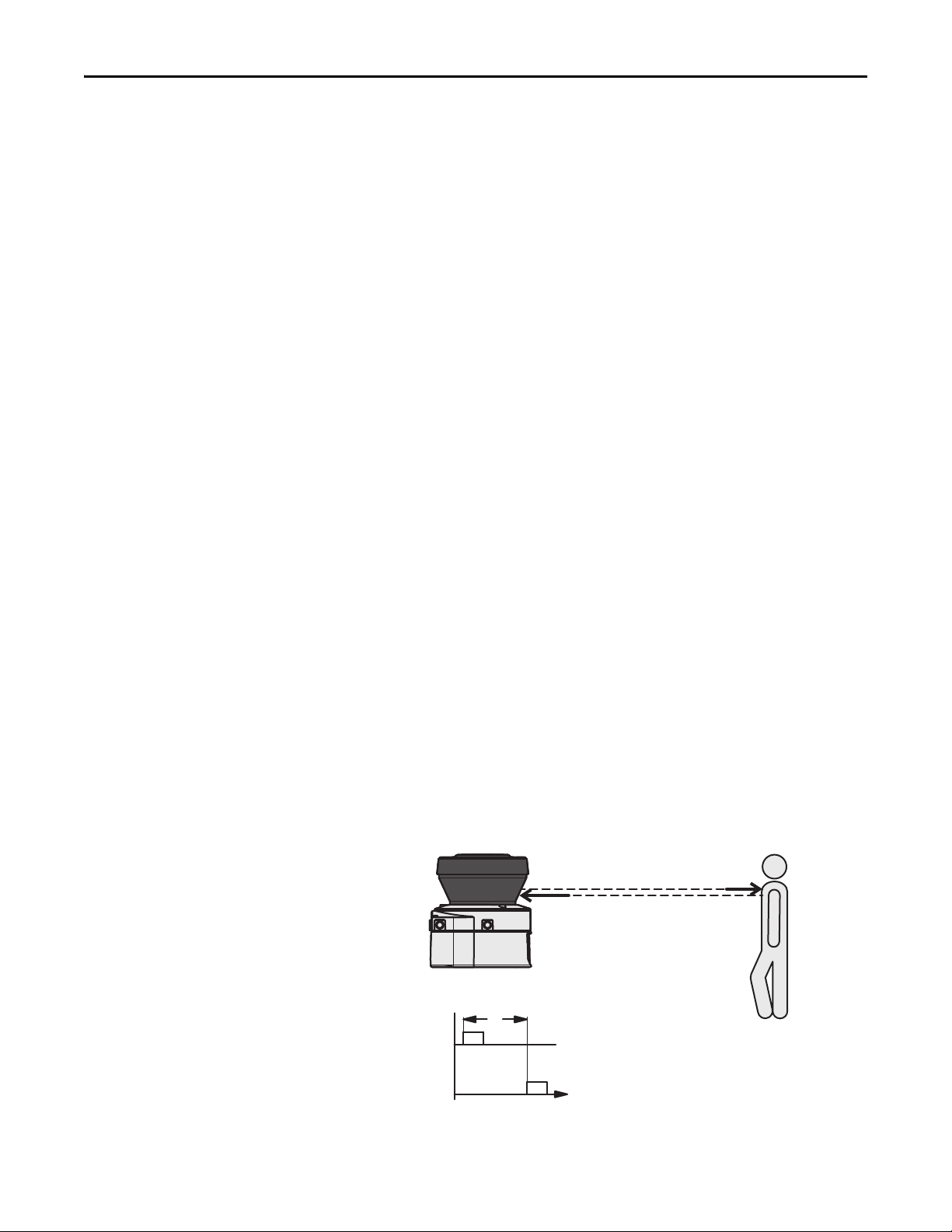
The SafeZone Mini is an optical sensor that scans its surroundings in two dimensions using infrared laser beams. It is used
to monitor hazardous areas on machines or vehicles.
Fig. 1: Principle of operation,
time-of-flight measurement
by the SafeZone Mini
10 Rockwell Automation Publication 10000337275 Ver 01—October 2014
Page 13
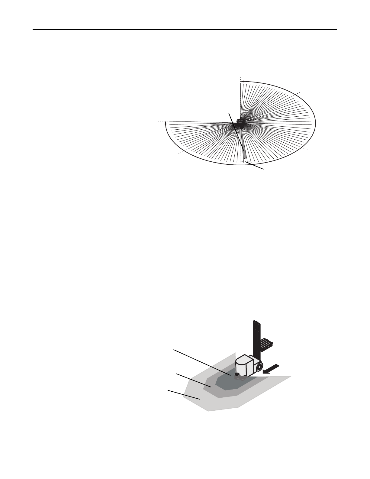
Fig. 2: Principle of operation,
225°
-45°
90°
0°
180°
Protective fie ld
Warn ing f ield 1
Warning field 2
rotation of the
SafeZone Mini
Chapter 3 Product description
The SafeZone Mini works on the principle of time-of-flight measurement. It sends out very short pulses of infrared light
(send pulses). At the same time an “electronic stopwatch” is started. When the light hits an object, it is reflected and
received by the safety laser scanner (receive pulses). From the time between sending and reception (t) the SafeZone
Mini calculates the distance to the object.
In the SafeZone Mini there is also a mirror rotating at constant speed that deflects the light pulses such that they cover an
arc of 270°. In this way an object can be detected in the protective field within 270°. The first beam of a scan starts at –45°
relative to the back of the safety laser scanner.
The SafeZone Mini sends a pulse of light with an angular resolution of 0.5° . As a result resolutions between 30 mm
(1.18 in.) and 70 mm (2.76 in.) can be achieved
.
Due to its active scanning principle, the SafeZone Mini does not require receivers or reflectors. This has the following
advantages:
• Your installation effort is lower.
• You can easily adapt the monitored area to the hazardous area on a machine.
• In comparison with contact sensors, electro-sensitive scanning is nearly wear-free.
Field set comprising protective field and warning field(s)
Protective fields and warning fields form the so-called field set. You can configure these field sets with the aid of the SCD
software. The fields can be configured as circular, rectangular or of arbitrary shape. If the area to be monitored changes,
then you can re -configure the SafeZone Mini in software without additional mounting effort.
You can configure field sets comprising one protective field and one or two warning fields.
The SafeZone Mini secures the hazardous area on a machine or vehicle. As soon as the safety laser scanner detects an
object in the protective field, it switches the OSSDs to the OFF state and thus initiates the shutdown of the machine or stop
of the vehicle.
Fig. 3: Field set with one
protective field and
two warning fields
You can define the warning fields such that the safety laser scanner detects an object before the actual hazardous area.
Warning field 1 can be used in particular fo r vehicle protection to detect an object even before the actual hazardous area
and to slowly retard the movement of the vehicle or bring it to a standstill. In this way the wear on the brakes on an AGV
can be reduced. Warning field 2 can also be used to trigger a warning signal.
Rockwell Automation Publication 10000337275 Ver 01—October 2014 11
Page 14
Chapter 3 Product description
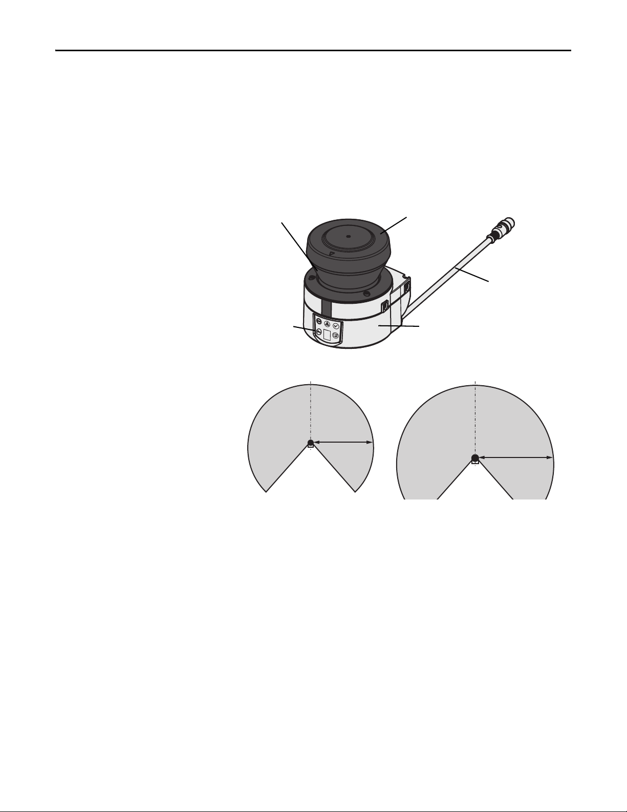
Window for light output
LEDs and sevensegment display
Optics cover
Sensor
Round plug
connector
Connecting cable
Max. 2 m
(6.6 ft)
Max. 3 m
(9.84 ft)
A warning field on the SafeZone Mini is not allowed to be used for tasks related to the protection of people.
Note
Contour monitoring
In addition to the protective field, the SafeZone Mini can also monitor a contour (e.g. the floor in vertical applications).
SafeZone Mini
Device components
The SafeZone Mini safety laser scanner comprises three components:
• The sensor with the opto-electronic detection system, the LEDs, the sevensegment display and the connecting cable
with the electrical connections
• The optics cover with the window for the light output
Fig. 4: Device components
Fig. 5: Protective Field Range
12 Rockwell Automation Publication 10000337275 Ver 01—October 2014
Page 15
Applications
Chapter 3 Product description
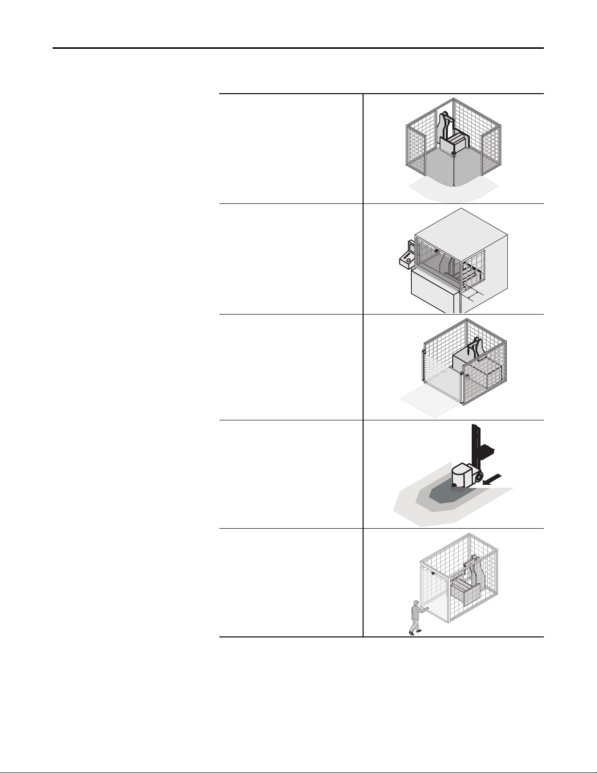
Table 2: Possible applications for the
SafeZone Mini
SafeZone Mini:
Hazardous area protection on an insertion station
SafeZone Mini:
Hazardous point protection on an insertion station
SafeZone Mini:
Presence detection for a safety light curtain
SafeZone Mini:
Protection of an automated guided vehicle (AGV) for
one velocity
Access protection for high areas of access
Rockwell Automation Publication 10000337275 Ver 01—October 2014 13
Page 16
Chapter 3 Product description
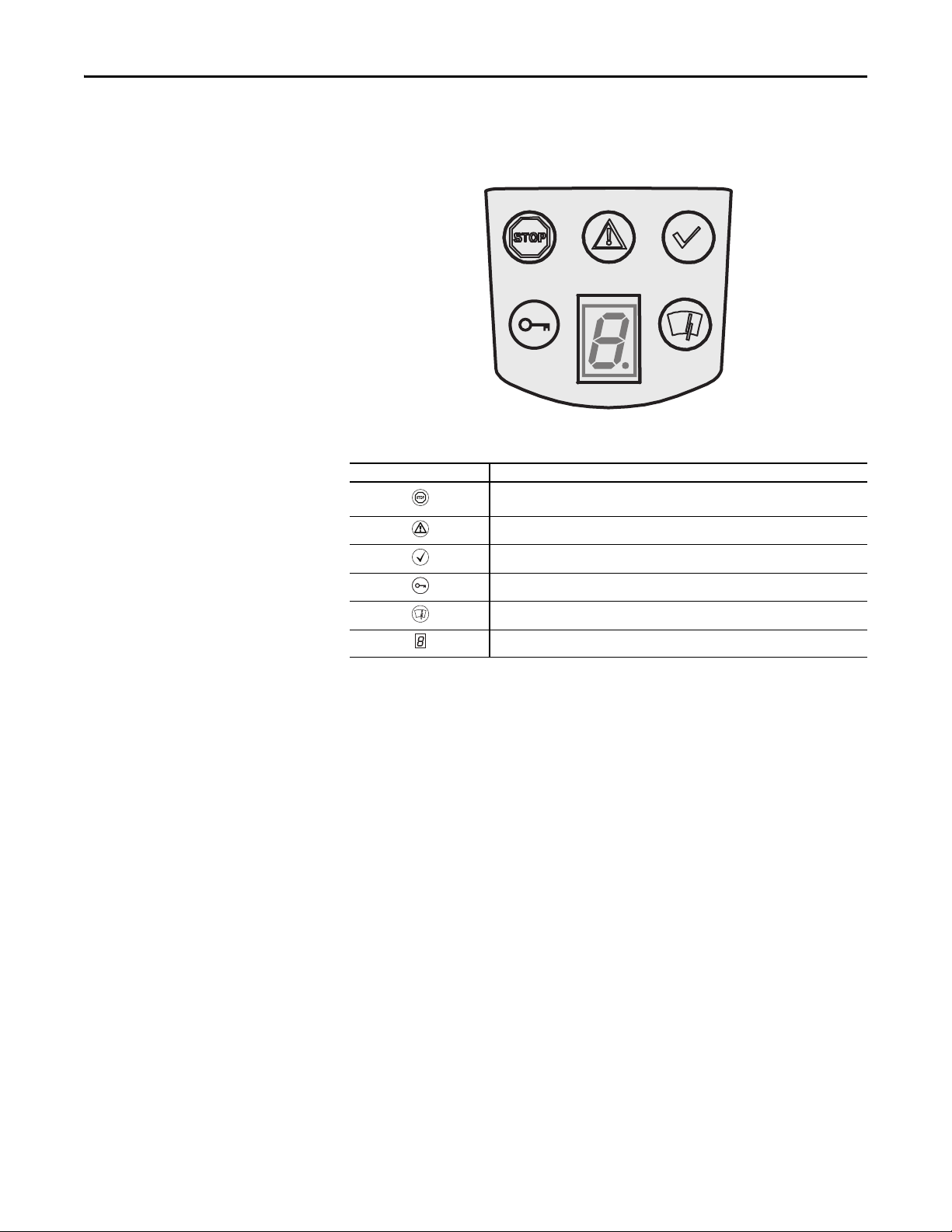
Status indicators
Fig. 6: Status indicators on the
Table 3: Status indicators on the
SafeZone Mini
SafeZone Mini
LEDs and sevensegment display
The LEDs and the sevensegment display indicate the operational status of the SafeZone Mini. They are on the front face of
the safety laser scanner.
The symbols have the following meaning:
Symbol SafeZone Mini
OSSDs in the OFF state (e.g. in case of object in the protective field, monitored contour
changed, reset required, lockout)
Warning field interrupted (object in one of the warning fields)
OSSDs in the ON state (no object in protective field)
Reset required
Optics cover contaminated
.
You will find detailed information in Chapter 11, “Error and status indications on the LEDs” on page 52 and in “Error and
Note
status indications on the sevensegment display” on page 52).
Sevensegment display for the indication of the status and errors
14 Rockwell Automation Publication 10000337275 Ver 01—October 2014
Page 17

Configurable functions
Chapter 4 Configurable functions
Chapter 4
System parameters
Recommendation
A name can be assigned to the application configured as well as to the safety laser scanner(s). The names are saved in the
devices after the configuration is transferred. The name chosen may be, for example, the identifier for the vehicle, system
or the machine.
You enter the application name and the names of the safety laser scanners used in the SCD software.
Application name
Enter a name for your application. You can enter a name with a maximum of 16 characters.
If you assign unique application names, you may “reserve” the devices for certain duties. A machine maintenance person
comparing exchanged devices with the configuration data saved in the SCD software will be notified that the application
name does not match. He may then exchange these devices for those with the correct application name.
Name of the scanner
Enter a device name for each of the safety laser scanners in the system. You can enter names with a maximum of eight
characters.
Use meaningful names, e.g. “front” and “rear” for vehicle monitoring. Unique device names make the subsequent
configuration steps easier (for example on allocating the control inputs or the OSSDs).
User data
You can enter your name in the field Name of the user. You can enter a name with a maximum of 22 characters. This is
then added to the configuration protocol and in the diagnostics report.
Display direction of the sevensegment display
The depiction of numbers on the sevensegment display can be rotated by 180° with the aid of the SCD software. This is
useful, for example, when the SafeZone Mini must be rotated by 180° owing to the specific assembly.
If you rotate the numbers of the sevensegment display, the point in the sevensegment display goes out.
How to determine the display direction of the sevensegment display:
Under sevensegment display, activate the Rotated by 180° option. After the configuration draft has been
transferred to the SafeZone Mini, the numbers of the sevensegment display are rotated by 180°.
Rockwell Automation Publication 10000337275 Ver 01—October 2014 15
Page 18
Chapter 4 Configurable function s
Application
With the help of the SCD software you can configure the SafeZone Mini for the required application. Depending on
whether you select a stationar y or a mobile application, different configuration options are available:
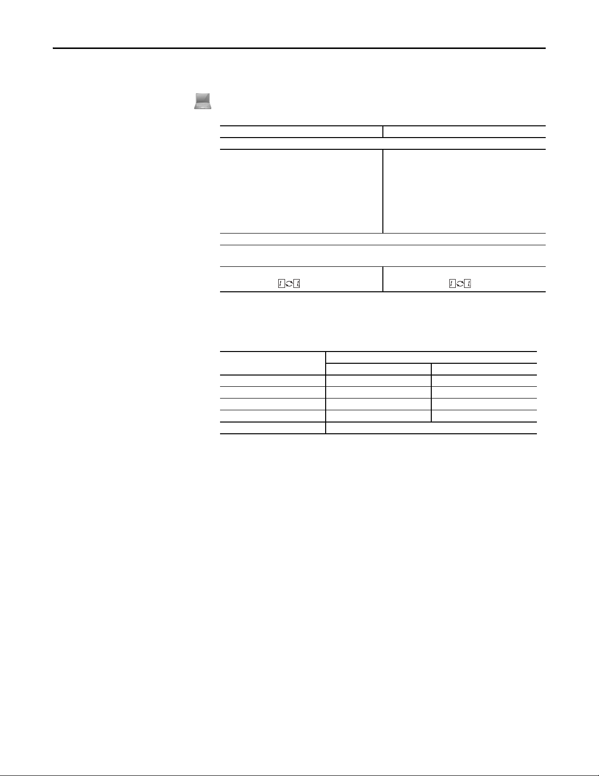
Table 4: Comparison of mobile and
stationary applications
Table 5: Maximum protective field
range at different resolutions
Mobile applications [mm (in.)] Stationary applications [mm (in.)]
Resolution
• 30 (1.2) (hand detection with smaller protective field
size)
• 40 (1.6) (hand detection with larger protective field
size)
• 50 (2.0) (leg detection with smaller protective field
size)
• 70 (2.8) (leg detection with larger protective field
size)
Manipulation prevention
The safety laser scanner checks whether in any 90° segment all measured values correspond to the maximum distance
value that can be measured.
If this is the case, the SafeZone Mini shuts down after
2hours and signals .
• 30 (1.2) (hand detection with smaller protective field
size)
• 40 (1.6) (hand detection with larger protective field
size)
• 50 (2.0) (leg detection with smaller protective field
size)
• 70 (2.8) (leg detection with larger protective field size)
• 150 (5.9) (whole body detection)
If this the case, the SafeZone Mini shuts down after
5seconds and signals .
Resolution
The maximum protective field range depends on the configured resolution. The following table shows the related
maximum protective field range at the resolutions that can be set:
Configured resolution [mm (in.)] Maximum protective field range [m (ft)]
2 m 3 m
30 (1.2) – (hand detection) 1.25 (4.1) 1.25 (4.1)
40 (1.6) – (hand detection) 1.60 (5.2) 1.60 (5.2)
50 (2.0) – (leg detection) 2.00 (6.6) 2.10 (6.89)
70 (2.8) – (leg detection) 2.00 (6.6) 3.00 (9.84)
150 (5.9) (whole body detection) 3.00 (9.84)
The warning field can be configured to up to 8 m (26.25 ft) for all resolutions. The detection capability within the warning
Note
field is dependent on the remission of the objects to be detected (see Chapter 12, “Technical Specifications” on page 55).
Basic response time
The basic response time of the SafeZone Mini is 80 ms.
You may need to add supplements to the basic response time due to multiple sampling (see Chapter 12, “OSSD response
Note
times” on page 55).
Maximum protective field range
Depending on the configured resolution used (see Chapter 4, “Resolution” on page 16), the maximum protective field
range of the safety laser scanner is shown in the SCD software.
The maximum protective field range of the SafeZone Mini must be sufficient to cover the calculated protective field size
Note
including the necessary supplements (see Chapter 5, “Protective field size” on page 25).
In mobile applications a resolution of only 70 mm (2.8 in.) is required for leg detection.
Radial distance to the safety scanner.
16 Rockwell Automation Publication 10000337275 Ver 01—October 2014
Page 19
Universal I/O connections of
the SafeZone Mini
Chapter 4 Configurable functions
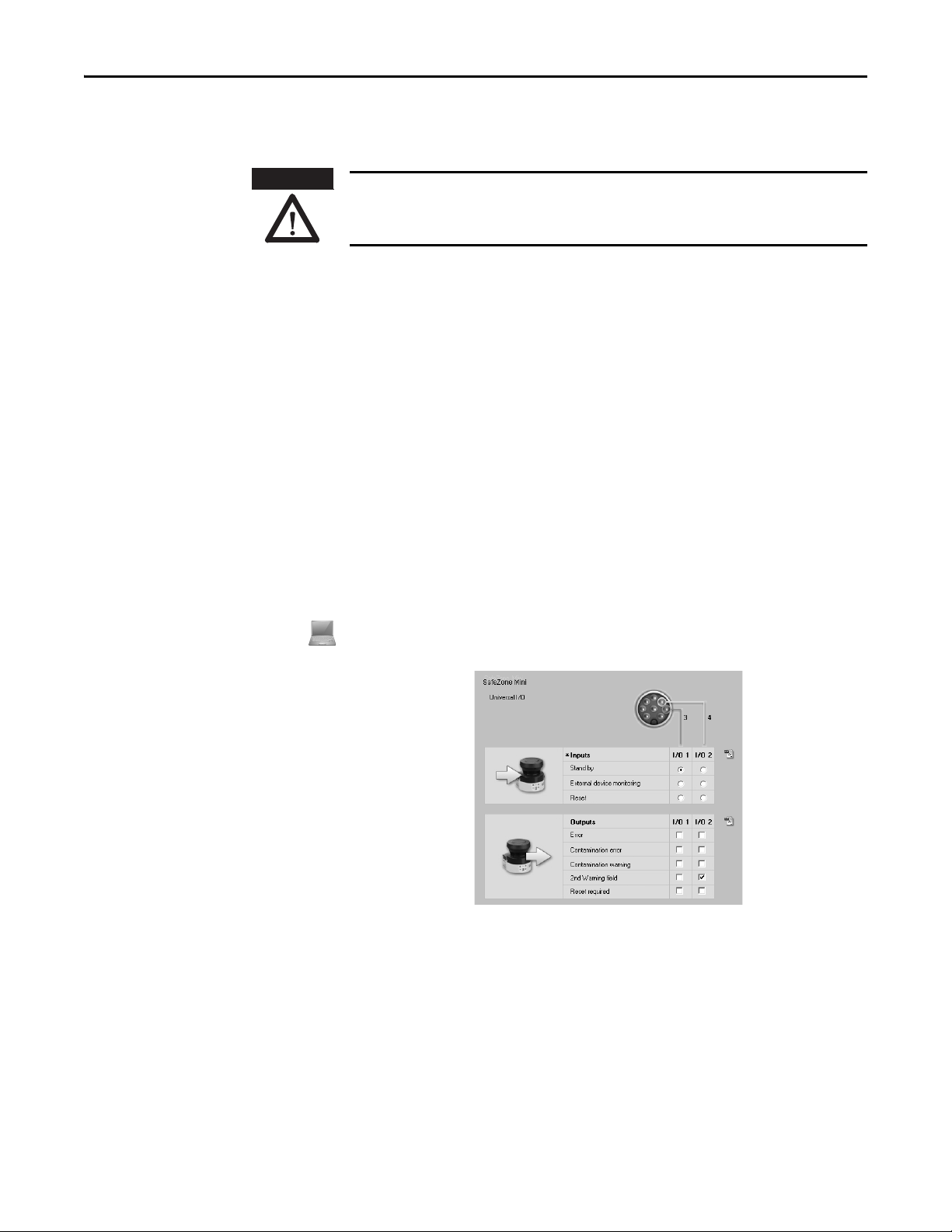
ATTENTION
Note
You are not allowed to use the universal I/O connections for safety-relevant functions!
You are only allowed to use the universal I/O connections for signaling. You must never use the signals for controlling the
application or for safety-relevant func tions.
The SafeZone Mini has two universal I/O connections (see Chapter 6, “Round plug connector SafeZone Mini” on page 40).
You can configure these two connections for the following functions:
• Inactive (factory default setting)
As inputs (it is only possible to select one function per universal I/O connection):
• Stand-by
• External device monitoring (EDM) (see page 18)
• Resetting the restart interlock (see page 18)
As outputs (it is possible to select several functions per universal I/O connection, these functions are linked
together using an OR operator):
• Device error
• Contamination error
• Contamination warning
• Second warning field
• Reset required
Other functions that can be configured are dependent on the configuration of the universal I/O connections. For example,
you can only realize a restart interlock if you configure one of the universal I/Os as an input for resetting the restart
interlock.
The universal I/O connections are configured in the SCD software in the Universal I/O area. Fig. 7 shows a configuration
example.
Fig. 7: Configuration example
universal I/O connections of the
SafeZone Mini
Recommendation
Stand-by
If, in mobile applications, vehicles are not moved for a time, the OSSDs can be switched to the OFF state and the laser on
the SafeZone Mini can be switched off. In this way the power consumption of the device is reduced.
Use this function if, e.g. you use several vehicles and do not move them for a time.
The SafeZone Mini remains in the stand-by mode as long as the related input information is present.
Rockwell Automation Publication 10000337275 Ver 01—October 2014 17
Page 20
Chapter 4 Configurable function s
.
OSSDs
Tab le 6 : Beh avi or o f th e
SafeZone Mini on a
contactor malfunction
Note
Internal OSSDs of the SafeZone Mini
If there is an object in the protective field, the internal OSSDs on the SafeZone Mini always switch. This can not be
configured differently in the SCD software.
External device monitoring (EDM) SafeZone Mini
The EDM checks if the contactors actually de-energize when the protective device is tripped. If you activate external device
monitoring, then the SafeZone Mini checks the contactors after each interruption of the protective field and prior to the
machine restart. The EDM can so identify if one of the contactors has welded, for instance. In this case the external device
monitoring places the system in a safe operational state and the OSSDs are not switched back to the ON state.
The table shows how the SafeZone Mini reacts if the external device monitoring detects a contactor malfunction:
Without internal restart interlock
or
with restart delay
With restart interlock
You can configure the external device monitoring in the SCD software.
You will find examples on the connection of the external device monitoring in Chapter 7, “Connection diagrams” on
page43.
• The system locks completely (lock-out).
• The error message 8 appears in the sevensegment display.
• The SafeZone Mini switches its OSSDs to the OFF state.
• The LED is illuminated.
• The error message e appears in the sevensegment display.
Restart of the SafeZone
Mini Standard
ATTENTION
You can configure the restart behavior of the SafeZone Mini as follows:
• Without restart interlock
• With restart delay
• With restart interlock
You can configure the type of restart in the SCD software.
It is imperative that you configure the SafeZone Mini or the application with restart interlock if the
protective field can be left to approach the hazardous point or if a person cannot be detected by the
SafeZone Mini at every point in the hazardous area!
During the assessment, pay attention to whether the protective field can be left in the direction of the hazardous point, to
areas that are unprotected due to the mounting and the unprotected near range of the SafeZone Mini (see Chapter 5,
“Methods of preventing unprotected areas” on page 33).
Configuration of the SafeZone Mini without restart interlock
After the OSSDs on the SafeZone Mini have been switched to the OFF state due to an object in the protective field, the
OSSDs are re-enabled again immediately when there is no longer an object in the active protective field.
This configuration is only allowed …
• If an external restart interlock is realized on the machine controller
or
• If the protective field cannot be left in the direction of the hazardous point and if people can be detected by the
SafeZone Mini at every point in the hazardous area!
Restart delay for mobile applications
In mobile applications you can configure a restart delay from 2 to 60 seconds on the SafeZone Mini. The OSSDs on the
SafeZone Mini change to the ON state if there is no object in the protective field for the duration given.
This configuration is only allowed if the protective field cannot be left in the direction of the hazardous point and if a
person can be detected at every point in the hazardous area by the SafeZone Mini!
18 Rockwell Automation Publication 10000337275 Ver 01—October 2014
Page 21
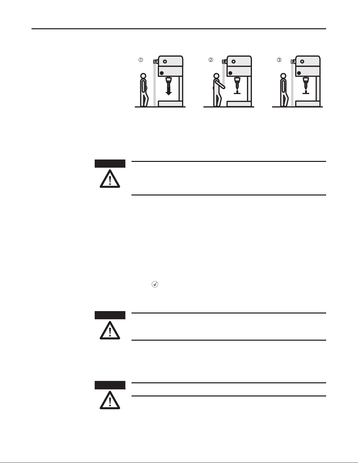
Fig. 8: Schematic outline of the
operation with restart interlock
Note
Chapter 4 Configurable functions
Configuration of the SafeZone Mini with restart interlock
Do not confuse the restart interlock with the star ting interlock on the machine. The starting interlock prevents the
machine starting after switching on. The restart interlock prevents the machine starting again after an error or a
protective field infringement.
The OSSDs on the SafeZone Mini change to the OFF state to initiate a machine or vehicle stop as soon as there is an
object in the protective field . They do not change to the ON state , even if there is no longer an object in the
protective field. The OSSDs only change to the ON state if the operator operates the control switch for restart or reset.
ATTENTION
Notes
Note
ATTENTION
Place the control switch for restart or reset outside the hazardous area in a place where it can clearly be
seen from the hazardous area!
Place the control switch for restart or reset outside the hazardous area such that it cannot be operated by a person in the
hazardous area. Ensure that the person who operates the control switch has a full view of the hazardous area.
• You will find examples on the connection of the internal restart interlock in Chapter 7, “Connection diagrams” on
page 43.
• If you do not use the internal restart interlock, then do not configure any of the universal I/Os as an input for
resetting (see Chapter 4, “Universal I/O connections of the SafeZone Mini” on page 17).
Reset
The reset function is often also called “preparation for restart.” In these operating instructions the term reset is used.
If you want to activate the restart interlock on the SafeZone Mini (internal) and also a restart interlock on the machine
(external), then each restart interlock has its own control switch.
After operating the control switch for the internal restart interlock (with protective field unoccupied) …
• The SafeZone Mini switches its OSSDs to the ON state.
• The LED on the SafeZone Mini illuminates green.
The external restart interlock prevents the machine from restarting. After resetting the SafeZone Mini the operator must
press the control switch to restart the machine controller.
Ensure that the correct sequence is followed!
The controller must be realized such that the machine only restarts if the SafeZone Mini is first reset and then the control
switch for restarting the machine controller is operated.
ATTENTION
Reset signals
If the SafeZone Mini safety laser scanner is operated using the “With restart interlock” function, then after a protective
field infringement and the subsequent clearing of the protective field, it requests a reset signal from the control system
(reset required).
The reset signal must be safety-related (single failure proof)!
Rockwell Automation Publication 10000337275 Ver 01—October 2014 19
Page 22
Chapter 4 Configurable function s
Field sets
Fig. 9: Creating a field set in the SCD software
Note
ATTENTION
Configuring the protective field and warning field
With the aid of the SCD software you can configure the field set, which comprises a protective field and two warning
fields . During this process you configure the shape and size of the protective and warning fields. You can realize any
field shape required.
The area to be monitored is scanned radially by the SafeZone Mini. The SafeZone Mini cannot see through objects during
this process. The area behind objects that are in the area to be monitored (pillars, grilles, etc.) can thus not be monitored.
Protective fields and warning field can cover up an angle of up to 270° and have different radial scanning ranges
depending on the resolution configured (see Chapter 4, “Resolution” on page 16).
Check the protec tive fields configured!
Prior to commissioning the machine or vehicle, check the configuration of the protective fields using the instructions in
Chapter 9, “Commissioning” on page 47 and using the “Checklist” on page 70.
Note
Fig. 10: Configuring protective
field and warning field
ATTENTION
If the protective field or the warning fields stretch as far as a wall or another object (pillar, neighboring machine,
shelf), there should be a distance of 100 mm (3.94 in.) between the protective field or warning field and the object to
prevent false triggering .
Secure unprotected areas!
If it is possible to access a narrow strip between the protective field and a wall or another object, you must protect this
strip using additional measures (e.g. fence or floor protection).
20 Rockwell Automation Publication 10000337275 Ver 01—October 2014
Page 23
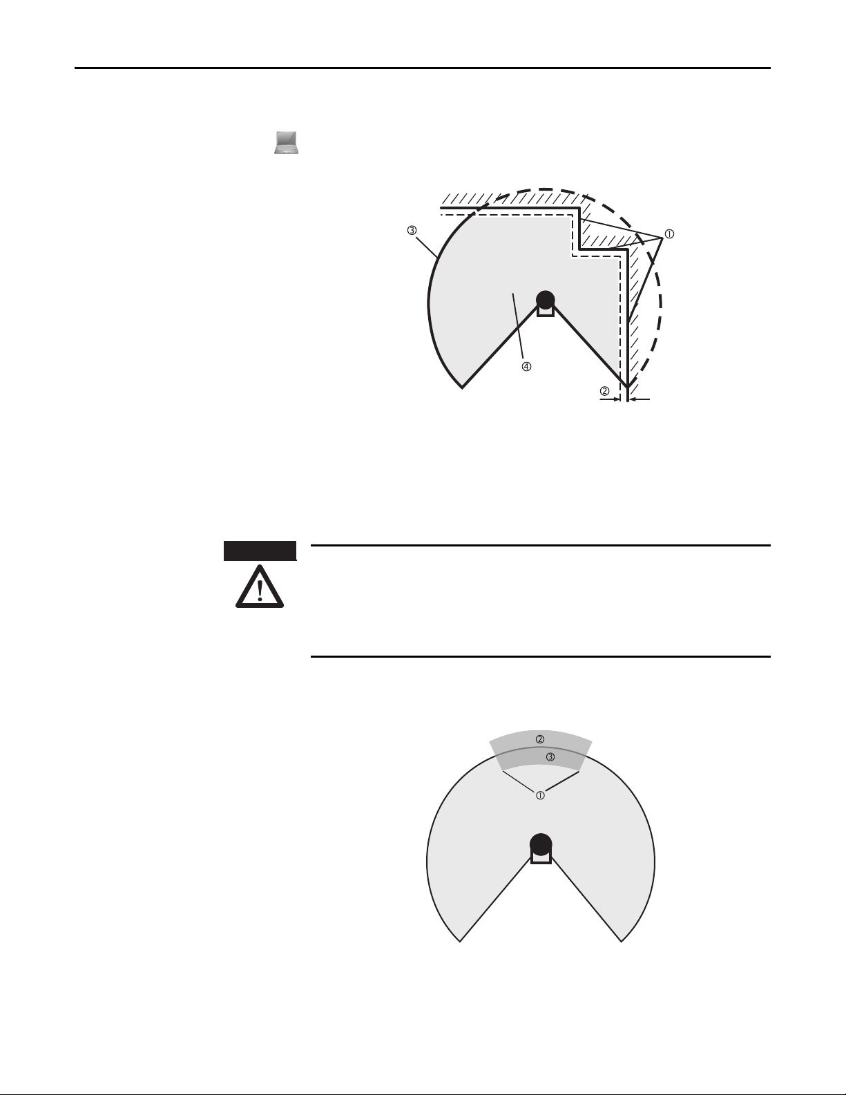
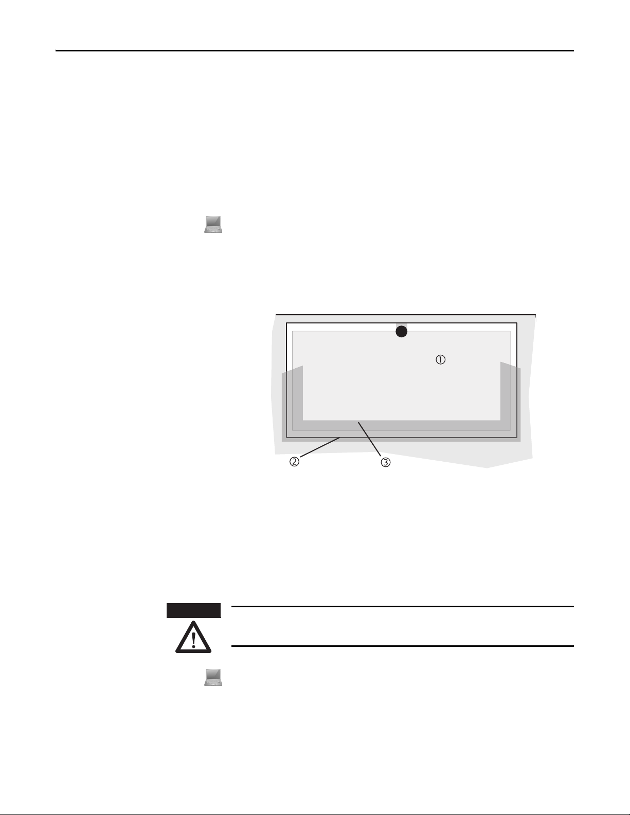
Fig. 11: Reading the protective field
Chapter 4 Configurable functions
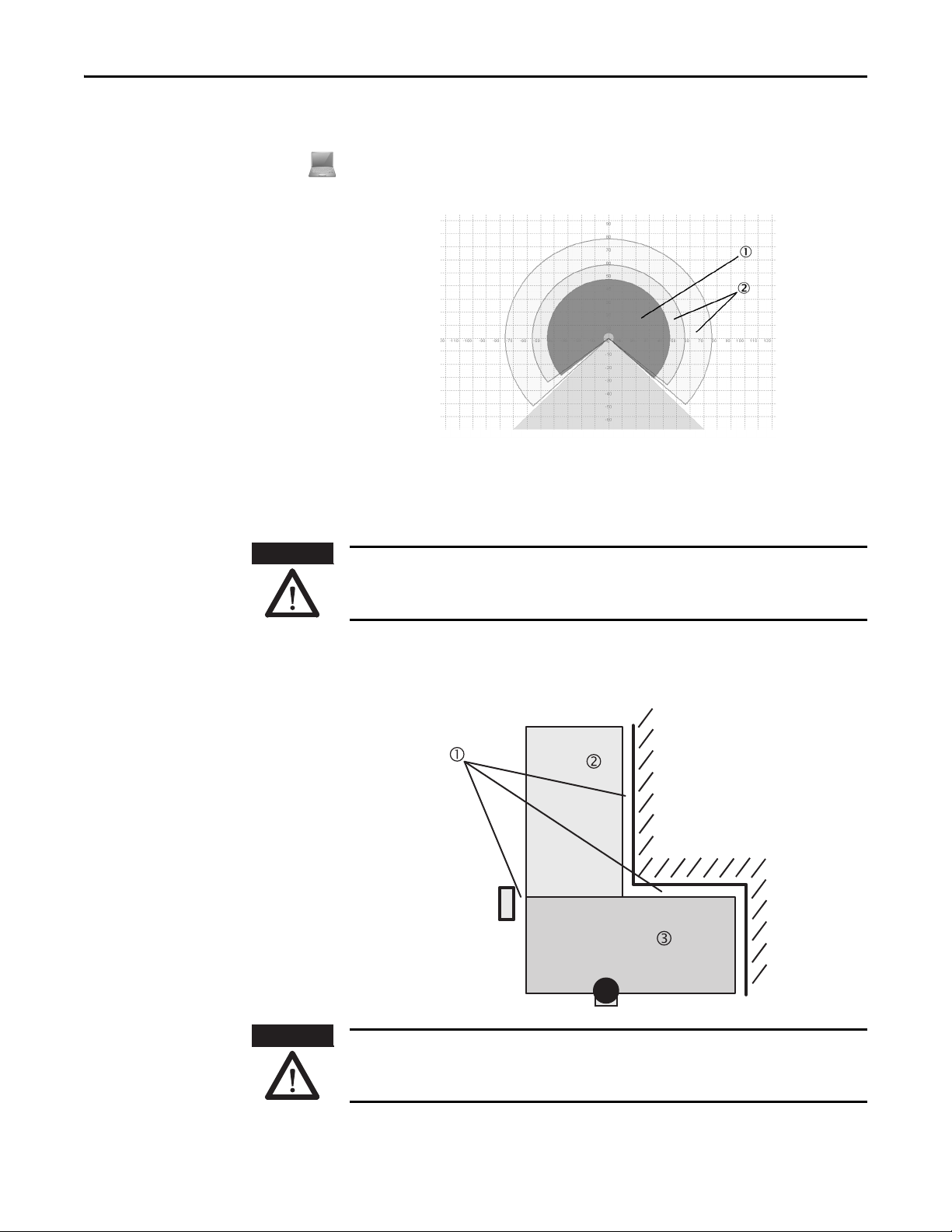
Protective field or warning field suggested by the safety laser scanner
The SCD software can suggest the protective field or warning field in the field set editor. The safety laser scanner scans the
visible surrounding contour several times. From the data obtained the SCD software suggests the contour and size of the
field. The following figure shows an example for the reading of a protective field:
In those places at which the surrounding contour is smaller than the maximum protective field range (e.g. at ), the
protective field corresponds to the surrounding contour.
Note
ATTENTION
Fig. 12: Schematic diagram of
contour as reference
The measuring error tolerances for the SafeZone Mini are automatically subtracted from the protective field size. As a
result the protective field is slightly smaller than the surface covered .
In those places where the surrounding contour is larger than the protective field range , the protective field corresponds
to the possible scanning range.
Check the protective field suggested by the SCD software
The protective field suggested by the SCD software is not a replacement for the calculation of the minimum distance.
Calculate the minimum distance and check the effectiveness of the protective fields prior to commissioning the
application!
Pay attention to the descriptions in Chapter 5, “Mounting” on page 24, the notes in Chapter 9, “Commissioning” on page
47 and the “Checklist” on page 70.
Using the contour as a reference
In addition to the protective field, the SafeZone Mini can also monitor a contour (e.g. the floor in vertical applications).
For contour monitoring you define a contour segment . The contour segment comprises a positive and a negative
tolerance band.
Rockwell Automation Publication 10000337275 Ver 01—October 2014 21
Page 24
Chapter 4 Configurable function s
Fig. 13: Contour as reference for
Contours of the machine opening
Notes
vertical operation
Protective field
Contour segment
The OSSDs on the SafeZone Mini change to the OFF state or the SafeZone Mini Remote signals if…
• There is an object in the protective field.
• The monitored surrounding contour is no longer in the tolerance band (e.g. if the position of the SafeZone Mini is
changed).
• You can define any number of contour segments.
• The contour segments must not be narrower than the configured resolution.
• At the points where a contour has been configured as a reference you cannot define warning fields. If, for example, you
use the floor as a reference for access protection, you cannot configure a warning field there. However, you can, e.g.,
configure a warning field to the left and right of the contour segment to control a warning signal on approach from the
side.
• The contour as reference function and the warning field 2 function are mutually exclusive.
You define the contour as a reference in the SCD software field set editor.
Vertical operation
In vertical operation (for access protection and hazardous point protection) according to CLC/TS 614963 you must always
configure the protective fields used with the contour as reference function.
Recommendation
Monitoring cases
ATTENTION
22 Rockwell Automation Publication 10000337275 Ver 01—October 2014
Use lateral, vertical boundaries of the opening (e.g. door frame) and the floor as reference. If in this case the position of the
SafeZone Mini is changed in one or more planes, the distance to the reference changes and the SafeZone Mini switches its
OSSDs to the OFF state.
The SafeZone Mini supports a configuration with monitoring cases.
Ensure for each monitoring case that the minimum distance to the hazardous area is maintained!
See Chapter 5, “Mounting” on page 24.
You can configure the monitoring cases in the SCD software.
Each monitoring case includes …
• The input conditions, the so-called control signals, that control the activation of the monitoring case.
• A field set, comprising of protective field and warning field or fields.
• The multiple sampling for the field set.
Monitoring cases can be switched with the following input information:
• Static information
Page 25

Chapter 4 Configurable functions
Multiple sampling
If multiple sampling is set, an objec t must be scanned several times before the SafeZone Mini switches its OSSDs to the OFF
state. In this way you can reduce the probability that insects, welding sparks or other particles result in the shutdown of
the system.
If a multiple sampling of three is configured, for instance, an object must be detected in the protective field three times in
succession before the SafeZone Mini switches the OSSDs to the OFF state.
ATTENTION
Table 7: Recommended
multiple sampling
Recommendation
The total response time is increased by the multiple sampling!
With a multiple sampling greater than two, note that you must add a supplement to the basic response time (see Chapter
12, “OSSD response times” on page 55)!
On the SafeZone Mini, a multiple sampling of two is the minimum setting. You can set the multiple sampling to up to 16
with the aid of the SCD software. The supplement to the basic response time resulting from your setting is displayed in the
SCD software.
Application Recommended multiple sampling
Stationary under clean ambient conditions 2 times
Vertical applications 2 times
Mobile 4 times
Stationary under dusty ambient conditions 8 times
Using multiple sampling you can increase the availability of a system.
You can configure the multiple sampling in the SCD software. You can set individual multiple sampling for each
monitoring case.
Stand-by mode
If, in mobile applications, vehicles are not moved for a time (e.g. for battery charging), the OSSDs can be switched to the
OFF state and the laser on the SafeZone Mini can be switched off. In this way the power consumption of the device is
reduced.
In this way you also prevent the safety laser scanners from optically interfering with each other and entering an error
condition.
The function can be realized with the aid of the stand-by mode.
In order to switch to the stand-by mode, on the SafeZone Mini one universal I/O connection must be configured as stand-
by input. (see Chapter 4, “Universal I/O connections of the SafeZone Mini” on page 17).
A monitoring case is not occupied by the stand-by mode.
Note
Rockwell Automation Publication 10000337275 Ver 01—October 2014 23
Page 26

Chapter 5 Mounting
Mounting
This chapter describes the preparation and completion of the mounting of the SafeZone Mini safety laser scanner.
Mounting requires four steps:
• Definition of the application and the necessary mounting location for the safety laser scanner
• Calculation of the protective field sizes and minimum distances (see EN ISO 13855)
• Mounting the safety laser scanner with or without mounting kits
No protective function without sufficient minimum distance!
Only if you configure the protective field such that there is an adequate minimum distance to the hazardous area, is
protection by the SafeZone Mini ensured.
Mount the SafeZone Mini in a dry place and protect the device from dirt and damage.
Notes
Avoid the installation of the SafeZone Mini in the vicinity of strong electric fields. These can, e.g., be produced by
welding cables, induction cables in the immediate vicinity and also by mobile telephones operated nearby.
Ensure that there are no obstacles in the area to be monitored in the field of view of the S afeZone Mini that could cause
interference or shadowing. Such shadowed areas cannot be monitored by the SafeZone Mini. If there are unavoidable
shadowed areas, check whether there is a risk. Take additional safety precautions as necessary.
Keep the area to be monitored free of smoke, fog, steam or other forms of air impurities. There must not be any
condensation on the optics cover. Otherwise the function of the SafeZone Mini may be impaired and incorrect
switching may occur.
Avoid placing highly reflective objects in the scan plane of the SafeZone Mini. Examples: Retroreflectors can affec t the
measurement results of the SafeZone Mini. Highly reflective objects within the protective field can blank a part of the
area to be monitored in certain circumstances.
Mount the SafeZone Mini such that it is not saturated by incident sunlight. Do not position stroboscopic and
fluorescent lights or other strong light sources directly in the scan plane as these may affect the SafeZone Mini in
specific circumstances.
Mark the protective field on the floor, if this is reasonable for the application (see EN 614961 in Chapter 7).
Chapter 5
Stationary application in
horizontal operation
Fig. 14: Horizontal stationary application
The following steps are necessary after mounting:
• Completing the electrical connections (Chapter 6, “Electrical installation”)
• Configuration of the protective field (Chapter 8, “Configuration”)
• Commissioning and checking of the installation (Chapter 9, “Commissioning”)
• Checking the function and safe shutdown (Chapter 9, “Test notes”)
This type of protective device is suitable for machines and systems on which, e.g. a hazardous area is not completely
enclosed by a guard.
24 Rockwell Automation Publication 10000337275 Ver 01—October 2014
Page 27

Chapter 5 Mounting
Dangerous state
K x (1
M
+ 1s)
2
G
+ 2R + O
S
For a horizontal stationary application determine …
• The protective field size to observe the necessary minimum distance.
• The height of the scan plane.
• The restart behavior.
• Measures to protect any areas not covered by the SafeZone Mini.
Once you have defined the protective field size, mark the boundaries of the protective field on the floor. In this way you
Note
will make the protective field boundaries visible for the operator and ease subsequent testing of the protective function.
Protective field size
The protective field must be so configured that a minimum distance (S) to the hazardous area is maintained. This safety
distance ensures that the hazardous point can only be reached after the dangerous state of the machine has been
completely stopped.
You can operate the SafeZone Mini in stationary horizontal operation with 30, 40, 50, or 70 mm (1.2, 1.6, 2.0, or 2.8 in.)
Note
resolution. The maximum protective field range for the SafeZone Mini is given by the resolution.
ATTENTION
Fig. 15: Minimum distance S
Ensure that a human leg can be detected with 70 mm (2.8 in.)resolution!
As per EN ISO 13855, mount the scan planes for horizontal stationary applications with 70 mm (2.8 in.) resolution at least
300 mm (11.8 in.) above the floor (see “Height of the scan plane at 70 mm resolution” on page 33).
The minimum distance S depends on:
• Approach speed of the body or parts of the body
• Stopping/run-down time of the machine or system
(The stopping/run-down time is shown in the machine documentation or must be determined by taking a
measurement.)
• Response time of the SafeZone Mini
• Supplements for general measurement errors and any measurement errors related to reflection
• Supplement for prevention of reaching over
• Height of the scan plane
• Possibly the time for switching between the monitoring cases
How to calculate the minimum distance S (see EN ISO 13855):
First, calculate S using the following formula:
S=(K×(T
+ TS)) + ZG + ZR + C
M
Where …
K = Approach speed (1600 mm/s (63 in./s), defined in EN ISO 13855)
T
= Stopping/run-down time of the machine or system
M
T
= Response time of the SafeZone Mini and the downstream controller
S
Z
= General safety supplement of the SafeZone Mini = 100mm (3.94 in.)
G
Z
= Supplement for measurement error related to reflection
R
C = Supplement for prevention of reaching over
Rockwell Automation Publication 10000337275 Ver 01—October 2014 25
Page 28

Chapter 5 Mounting
C = 1200 (47.2) C = 850 (33.5) C = 850 (33.5)
h
s
hD = 0
h
s
hD = 875 (34.4)
h
s
hD = 875 (34.4)
Response time TS of the SafeZone Mini
The response time T
of the SafeZone Mini depends on …
S
• The basic response time of the SafeZone Mini.
• The multiple sampling set.
See Chapter 12 “OSSD response times” on page 55.
Supplement ZR for measurement errors caused by reflection
ATTENTION
Fig. 16: Mounting variations
for the scan plane [mm (in.)]
Avoid mounting retroreflectors at a distance of less than one meter from the boundary of the protective
field!
With retroreflectors positioned at a distance of less than 1 m (39.4 in.) from the boundary of the protective field a
supplement, Z
, of 200 mm (7.87 in.) must be added to the protective field.
R
Supplement C for protection against reaching over
With a protective field installed horizontally, there is a risk that people may reach over the protective field and in this way
reach the hazardous area before the SafeZone Mini shuts down the dangerous state. For this reason the calculation of the
minimum distance must take into account a supplement to prevent persons from finding themselves in a hazardous
situation by reaching over (see EN ISO 13857) before the SafeZone Mini triggers.
The necessary supplement for the minimum distance is dependent on the height of the scan plane for the protective field.
At low heights the supplement is larger than at greater heights and .
In summary there are three usual variations of mounting the scan plane for the SafeZone Mini. The optimal variation
depends on the related application. Table 8 provides assistance making the selection.
Table 8: Advantages and disadvantages of mounting
variations [mm (in.)]
H
= Detection height
D
H
= Scanner mounting height
S
Safety laser scanner low (H
Low inclination of the scan plane (H
Safety laser scanner high (H
Low inclination of the scan plane (H
Safety laser scanner low (HS< 3300 (11.81 in.))
High inclination of the scan plane (H
ATTENTION
In case of scan planes at a height of more than 300 mm (11.81 in.) ensure that people cannot reach the
hazardous area by crawling underneath the scan plane!
If you mount the protective device higher than 300 mm (11.81 in.), you must prevent crawling beneath by means of
additional measures. For applications that are accessible to the public, the mounting height may need to be reduced to
200 mm (7.87 in.)(on this subject see the appropriate regulations).
26 Rockwell Automation Publication 10000337275 Ver 01—October 2014
Mounting orientation Benefit Disadvantage
< 300 (11.81 in.))
S
HS)
D
> 300 (11.81 in.))
S
HS)
D
)
D>HS
Low external effects due to ambient
Higher supplement C
light inter ference, crawling beneath
not possible
Lower protective field supplement C Danger of crawling beneath (at
the front and side)
Lower protective field supplement C Danger of crawling beneath (at
the front), external effect due to
ambient light interference
possible
Page 29

Note
Fig. 17: Relationship between
resolution and protective
field mounting height
Chapter 5 Mounting
How to calculate the supplement C:
If there is enough empty space in front of your machine or system, use 1200 mm (47.2 in.) for the supplement C.
If the minimum distance is to be kept as small as possible, calculate C using the following formula:
C = 1200 mm – (0.4 × H
Here H
is the height at which the protective field is mounted.
D
The minimum supplement C to prevent reaching over is 850 mm (33.5 in.)(arm length).
Height of the scan plane at 70 mm (2.8 in.) resolution
Due to the radial sampling of the protective field, the optical resolution will be lower the further away you get from the
safety laser scanner.
)
D
Stationary vertical operation
for access protection
Notes
If you choose a resolution of 70 mm (2.8 in.) in the SCD software for hazardous area protection, a human leg may, in
certain circumstances, not be detected (e.g. scan to left and right of the bone ).
If you mount the SafeZone Mini higher, the scan plane is at fibula height and the leg is also detected with an object
resolution of 70 mm (2.8 in.) .
Access protection can be used when the access to the machine can be defined by physical means. For access protection the
SafeZone Mini detects the entry of an entire body.
• To ensure adequate access protection, a response time of 90 ms and a resolution of 150 mm (5.91 in.) or finer are
required .
• To protect the protective device against inadvertent adjustment or manipulation, you must use the contour of the
surroundings as a reference for the SafeZone Mini (see Chapter 4, “Using the contour as a reference” on p age 21).
Minimum distance
For access protection, a minimum distance (S) must be maintained between protective field and hazardous area. This
safety distance ensures that the hazardous point can only be reached after the dangerous state of the machine has been
completely stopped.
Rockwell Automation Publication 10000337275 Ver 01—October 2014 27
Page 30

Chapter 5 Mounting
Protective fie ld
Contour of the floor
as refere nce
S
Fig. 18: Access protection
The minimum distance S as defined in EN ISO 13855 and EN ISO 13857 depends on:
• Reach or approach speed
• Stopping/run-down time of the machine or system
(The stopping/run-down time is shown in the machine documentation or must be determined by taking a
measurement.)
• Response time of the SafeZone Mini
• Supplement C against reaching through
ATTENTION
How to calculate the minimum distance S (see EN ISO 13855):
First, calculate S using the following formula:
S=(K×(T
+ TS)) + C
M
Where …
K = Approach speed (1600 mm/s (63 in./s), defined in EN ISO 13855)
T
= Stopping/run-down time of the machine or system
M
TS= Response time of the SafeZone Mini
C = Supplement against reaching through (850 mm (33.5 in.))
Response time T
of the SafeZone Mini
S
The total response time of the SafeZone Mini must not be more than 80 ms for access protection!
If a critical response time is exceeded, a person may no longer be detected under certain circumstances.
In specific cases agreed with the responsible authorities higher response times may be allowed (for example by increasing
the detection time available by positioning the safety laser scanner at an angle). In this case ensure that the areas the
safety laser scanner cannot see are protected by additional measures.
The response time T
of the SafeZone Mini depends on …
S
• The basic response time of the SafeZone Mini.
• The multiple sampling set.
See Chapter 12, “OSSD response times” on page 55.
28 Rockwell Automation Publication 10000337275 Ver 01—October 2014
Page 31

Chapter 5 Mounting
Contour as
referenc e
Stationary vertical operation
for hazardous point
protection
Note
ATTENTION
ATTENTION
Fig. 19: Minimum distance to the hazardous area
Hazardous point protection is necessary if the operator must remain near the dangerous state of the machine. Hand
protection is required for hazardous point protection.
The SafeZone Mini must therefore be configured with a resolution of at least 40 mm (1.6 in.)
Never use the SafeZone Mini for safety applications in which finger protection is required!
Due to the finest possible resolution of 30 mm (1.2 in.), the SafeZone Mini is not suitable for finger protection.
To protect the protective device against inadvertent adjustment or manipulation, you must use the contour of the
surroundings as a reference for the SafeZone Mini (see Chapter 4, “Using the contour as a reference” on page 21).
Minimum distance
For hazardous point protection, a minimum distance must be observed between protective field and hazardous point. This
safety distance ensures that the hazardous point can only be reached after the dangerous state of the machine has been
completely stopped.
Prevent reaching around or reaching behind the protective field!
Always mount the safety laser scanner such that reaching around and behind is impossible. Provide suitable additional
precautions as necessary.
The minimum distance S as defined in EN ISO 13855 and EN ISO 13857 depends on:
• Stopping/run-down time of the machine or system
(The stopping/run-down time is shown in the machine documentation or must be determined by taking a
measurement.)
• Response time of the SafeZone Mini
• Reach or approach speed
• Resolution of the SafeZone Mini
How to calculate the minimum distance S (see EN ISO 13855):
First, calculate S using the following formula:
S = 2000 × (T
Where …
S = Minimum distance [mm]
T
= Stopping/run-down time of the machine or system
M
T
= Response time of the SafeZone Mini
S
d = Resolution of the SafeZone Mini [mm]
Rockwell Automation Publication 10000337275 Ver 01—October 2014 29
+ TS) + 8 × (d – 14) [mm]
M
Page 32

Chapter 5 Mounting
The reach/approach speed is already included in the formula.
Note
If the result S is 500 mm (19.7 in.), then use the determined value as the minimum distance.
If the result S is > 500 mm (19.7 in.), you may be able to reduce the minimum distance using the following
calculation:
S = 1600 × (T
+ TS) + 8 × (d – 14) [mm]
M
If the new value S is > 500 mm (19.7 in.), then use the newly calculated value as the minimum distance.
If the new value S is 500 mm (19.7 in.) then use 500 mm (19.7 in.) as the minimum distance.
Mobile applications
Response time T
The response time T
of the SafeZone Mini
S
of the SafeZone Mini depends on …
S
• The basic response time of the SafeZone Mini.
• The multiple sampling set.
See Chapter 12, “OSSD response times” on page 55.
If the dangerous state is produced by a vehicle (e.g. AGV or fork lift), the hazardous area that is produced by the movement
of the vehicle is protected by the SafeZone Mini.
• The SafeZone Mini may only be used to protect vehicles powered by electric motor.
Notes
• In the following calculations only take into account the velocity of the vehicle, not the speed of the person walking.
This is based on the assumption that the person will recognize the danger and stand still.
• For vehicle protection, observe EN 1525 “Safety of industrial trucks. Driverless trucks and their systems.”
• If the application is to protect vehicles from collisions, then you may need to use different assumptions.
For a horizontally mounted mobile application, determine:
• Protective field length
• Protective field width
• Height of the scan plane
• Restart behavior
• Methods of preventing unprotected areas
Protective field length
You must configure the protective field such that a minimum distance to the vehicle is maintained. This ensures that a
vehicle monitored by the SafeZone Mini comes to a stop before a person or object is reached.
How to calculate the protective field length S
(see EN ISO 13855):
L
Calculate the necessary protective field length SL using the formula:
S
=SA +ZG +ZR +ZF +Z
L
B
Where …
=Stopping distance
S
A
ZG= General safety supplement of the SafeZone Mini = 100mm (3.94 in.)
Z
= Supplement for any reflection related measurement error of the SafeZone Mini
R
Z
= Supplement for any lack of ground clearance of the vehicle
F
Z
= Supplement for the reduction in the braking performance of the vehicle to be found in the related
B
vehicle documentation
Stopping distance S
A
The stopping distance comprises the braking distance for the vehicle, the distance covered during the response time of the
safety laser scanner and the response time of the vehicle controller.
30 Rockwell Automation Publication 10000337275 Ver 01—October 2014
Page 33

Fig. 20: Stopping distance
SafeZone Mini
S
AnF
S
AnS
S
Br
Stopping distance
Stopping distance +
safety supplements
Necessary protective
field length
Speed
Note
Fig. 21: Stopping distance as
a function of the vehicle velocity
Chapter 5 Mounting
Take into account that the braking distance for a vehicle is not linear with increasing velocity, but increases in a square
function.
How to calculate the stopping distance SA:
Calculate the stopping distance SA using the formula:
S
A
=SBr + S
AnF
+ S
AnS
Where …
S
= Braking distance, to be found in the vehicle documentation
Br
S
= Distance covered during the response time of the vehicle controller, to be found in the vehicle documentation
AnF
S
= Distance covered during the response time of the safety laser scanner
AnS
Distance covered during the response time of the safety laser scanner
The distance covered during the response time of the safety laser scanner depends on …
• The response time of the safety laser scanner.
• The maximum velocity of the vehicle in your mobile application.
The response time T
of the SafeZone Mini depends on …
S
• The basic response time of the SafeZone Mini.
• The multiple sampling set.
See Chapter 12, “OSSD response times” on page 55
How to calculate the distance S
covered during the response time of the safety
AnS
laser scanner:
Calculate the distance S
S
AnS=TS×Vmax
using the formula:
AnS
Where …
T
= Response time of the safety laser scanner
S
V
= Maximum velocity of the vehicle from the related vehicle documentation
max
Rockwell Automation Publication 10000337275 Ver 01—October 2014 31
Page 34

Chapter 5 Mounting
SafeZone Mini
Protective field length
Ground clearance
2
F
120
60
50
0 50 100 150
Supplement 2F in mm
Ground clearance of the
vehicle in m m
Supplement ZR for measurement errors caused by reflection
With retroreflectors in the background at a distance of less than 1 m (39.4 in.) from the boundary of the protective field,
the supplement ZR is 200 mm (7.87 in.).
Fig. 22: Supplement due to lack of ground clearance
Fig. 23: Diagram of ground clearance of the vehicle
Supplement Z
due to lack of ground clearance
F
This supplement is necessary because a person is generally detected above the foot and the braking action can therefore
not take into account the length of the foot in front of the detection point. If a vehicle has no ground clearance, a person
may receive foot injuries.
S
A
The flat rate supplement for ground clearance below 120 mm (4.7 in.) is 150 mm (5.91 in.). This supplement can be
further reduced in specific cases. For this purpose read off the actual supplement necessary for the ground clearance of
your vehicle from the diagram below:
32 Rockwell Automation Publication 10000337275 Ver 01—October 2014
Protective field width
The width of the protective field must cover the width of the vehicle and the supplements for the measurement error and
the lack of ground clearance.
How to calculate the protective field width SB (see EN ISO 13855):
Calculate the protective field width S
S
=FB + 2 × (ZG + ZR + ZF)
B
Where …
F
=Vehicle width
B
Z
= General safety supplement of the SafeZone Mini = 100mm (3.94 in.)
G
Z
= Supplement for any reflection related measurement error of the SafeZone Mini
R
Z
F
= Supplement for any lack of ground clearance of the vehicle
using the formula:
B
Page 35

Height of the scan plane
Set protective
field length
190 (7.48)
150 (5.91)
Set protective
field length
110 (4.33)
150 (5.91)
?
Chapter 5 Mounting
ATTENTION
Fig. 24: Mounting height [mm (in.)]
Mount the SafeZone Mini such that the scan plane is at a maximum height of 200 mm (7.87 in.)!
In this way also persons lying down will be reliably detected. Tilting the protective field so that objects with a diameter of
200 mm (7.87 in.)are not detected, is not allowed. We recommend aligning the scan plane horizontally at 70 mm
(2.76 in.)
Methods of preventing
unprotected areas
Fig. 25: Unprotected areas
ATTENTION
Note
To produce the optimal scan plane, you can also mount the SafeZone Mini reversed.
During mounting the SafeZone Mini, areas may be found that are not covered by the safety laser scanner ().
Prevent or secure unprotected areas!
• Mount the SafeZone Mini such that there are no unprotected areas.
• For mobile applications, if the vehicle is accelerated to a maximum velocity of 0.3 m/s (11.8 in.s) in less than three
seconds when in operation, you must prevent personnel from entering the unprotected areas by means of mechanical
trim panels, switch strips or fitting the SafeZone Mini in the vehicle trim panels.
Rockwell Automation Publication 10000337275 Ver 01—October 2014 33
Page 36

Chapter 5 Mounting
Protective field and
warning field safety
laser scanner 1
Protective field and
warning field safety
laser scanner 2
Protective field and
warning field safety
laser scanner 1
Protective field and
warning field safety
laser scanner 2
Fig. 26: Preventing unprotected areas
Fig. 27: Mounting example for front and side
protection in a direction of travel
Mount the SafeZone Mini for example on a corner to prevent unprotected areas.
With two SafeZone Mini mounted at an angle of 45° on the front corners of a vehicle, you can configure the protective
fields so that there are no unprotected areas and the hazardous areas in narrow aisles can also be protected.
Fig. 28: Mounting example for
all-round protection in
all directions of travel
With two SafeZone Mini mounted diagonally opposite, you can implement protective fields on the vehicle for all-round
protection in all directions of travel.
34 Rockwell Automation Publication 10000337275 Ver 01—October 2014
Page 37

Mounting steps
Chapter 5 Mounting
Near range
Make the near range impassible using a bar or a recess, or additionally protect the near range (50 mm (2.0 in.)) wide area
in front of the optics cover) using a proximity switch with 50 mm (2.0 in.) acquisition range. The vehicle may then be
accelerated as required.
ATTENTION
Fig. 29: Prevent crawling beneath,
standing behind, climbing over
Only qualified safety personnel are allowed to separate materials!
Caution is required when dismantling devices. There is a risk of injuries.
Special features to note during mounting:
Mount the SafeZone Mini such that it is protected from moisture, dirt and damage.
Ensure that the entire field of view of the SafeZone Mini is not restricted.
Mount the safety laser scanner such that the indicators are easy to see.
Avoid excessive shock and vibration loading on the safety laser scanner.
On systems that suffer from heavy vibration, prevent the fixing screws from coming loose using screw locking devices.
Regularly check the tightness of the fixing screws.
Prevent personnel from being able to crawl beneath, stand behind or climb over the protective field by means of
appropriate mounting of the SafeZone Mini.
The origin of the scan plane is 80 mm (3.15 in.) above the bottom edge of the SafeZone Mini (see Fig. 54 on page 61).
There are three possible ways of fixing the SafeZone Mini:
• Direct mounting without mounting kit
• Mounting with mounting kit 1 or 2
• Mounting with mounting kit 3 (only in conjunction with mounting kit 1 or 2)
You will find the part numbers for the mounting kits in Chapter 13, “Mounting kits” on page 62.
Pay attention to the maximum torque of the M5 fixing screws on the SafeZone Mini of max. 5.9 Nm (4.4 ft-lb).
Note
Rockwell Automation Publication 10000337275 Ver 01—October 2014 35
Page 38

Chapter 5 Mounting
M5 x 8
Mounting kit 2
Mounting screws
Mounting screws
Threade d holes M5 x 8
Fig. 30: Direct mounting
Notes
Direct mounting
The SafeZone Mini has two threaded holes M5×8 on the rear. Using them you can mount the SafeZone Mini directly on the
intended mounting surface. To avoid a possible tendency to vibrate, if necessary the reference surface on the rear can be
used as the third mounting point .
During mounting, please observe the dimensional drawings in Chapter 12, “Dimensions” on page 61.
Fig. 31: Mounting with mounting kit 2
including protection for the optics cover
Note
Mounting with mounting kit 1or 2
With the aid of mounting kit 1 or 2 you can mount the SafeZone Mini indirectly on the mounting surface. Mounting kit 1 is
available as a mounting kit without protection device for the optics cover and as mounting kit 2 with protection device for
the optics cover.
Mount mounting kit 1 or 2 on the mounting surface.
Then mount the SafeZone Mini on the mounting kit 1 or 2.
During mounting, please observe the dimensional drawings in Chapter 12, “Technical specifications” (see “Dimensions”
on page 61).
Mounting with mounting kit 3 and 4
With the aid of mounting kits 3 and 4 (only in conjunction with mounting kit 1 or 2) you can align the SafeZone Mini in
two planes. The maximum adjustment angle is ±11° in both planes.
36 Rockwell Automation Publication 10000337275 Ver 01—October 2014
Page 39

Fig. 32: Mounting with mounting kit 2
Mounting kit 1
Mounting screws
Mounting screws
Threaded holes M4
Mounting kit 3 Mounting kit 4
Centering pin
Min. 3°
Min. 100 mm
Chapter 5 Mounting
Mount mounting kit 1 or 2 to the SafeZone Mini.
Mount the mounting kit 4 on the mounting surface.
Fit the centering pin [4 mm (0.16 in.)] in the central hole on mounting bracket 4.
Fit mounting kit 3 to mounting kit 4 and mount it using two fixing screws M4 ×10.
Then mount the SafeZone Mini on mounting kit 3 with the aid of the threaded holes in mounting kit 1.
Adjust the SafeZone Mini longitudinally and transversely and then tighten the six fixing screws on the mounting kits.
Fig. 33: Opposite mounting
Fig. 34: Offset parallel mounting
During mounting, please observe the dimensional drawings in Chapter 12, “Technical specifications” (see “Dimensions”
Note
on page 61).
Information label Important information
>On completion of mounting, you must affix the self-adhesive information label Important information supplied:
– Use only the information label in the language which the operators of the machine can read and understand.
– Place the information label such that it is clearly visible for the operators during operation. The information
label must not be covered even after additional items have been mounted.
Using multiple SafeZone Mini safety laser scanners
The SafeZon e Mini is designe d so that mutual inte rference betwee n several safety la ser scanners is u nlikely. To completel y
exclude erroneous switching, you must mount the safety laser scanners as shown in the following examples.
In any circumstance observe EN ISO 13855 when calculating the minimum distance.
Note
Use mounting kits 1 or 2 and 3 to adjust the safety laser scanners to different angles (see Chapter 13, “Mounting kits” on
page 65).
Rockwell Automation Publication 10000337275 Ver 01—October 2014 37
Page 40

Chapter 5 Mounting
Min. 3°
Min. 100 mm (3.94 in.)
Min. 100 mm (3.94 in.)
Fig. 36: Reverse mounting, parallel offset
Fig. 37: Reverse mounting of two
SafeZone Mini, with parallel offset
Fig. 35: Mounting on a cross
38 Rockwell Automation Publication 10000337275 Ver 01—October 2014
Page 41

Electrical installation
Chapter 6 Electrical installation
Chapter 6
ATTENTION
Switch the entire machine/system off line!
The machine/system could unintentionally start up while you are connecting the devices.
Ensure that the entire machine/system is disconnected during the electrical installation.
Connect OSSD1 and OSSD2 separately!
You are not allowed to connect OSSD1 and OSSD2 together, otherwise signal safety will not be ensured.
Ensure that the machine controller processes the two signals separately.
Downstream contactors must be positively guided and monitored.
OSSD1
OSSD2
Only ever connect one downstream switching element to an OSSD!
Each output signal switching device (OSSD) is only allowed to be connected to one switching element (e.g. relay or
contactor). If several switching elements are required, you must choose a suitable form of contac t duplication.
OSSD1
OSSD2
Prevent the occurrence of a potential difference between the load and the protective device!
If you connect loads that are not reverse-polarity protected to the OSSDs or the safety outputs, you must connect the 0
V connections of these loads and those of the corresponding protective device individually and directly to the same 0 V
terminal strip. This is the only way to ensure that, in the event of a defect, there can be no potential difference
between the 0 V connections of the loads and those of the corresponding protective device.
OSSD1
OSSD2
Safety output 1
Safety output 2
Rockwell Automation Publication 10000337275 Ver 01—October 2014 39
OSSD1
Safety output 1
OSSD2
Safety output 2
Page 42

Chapter 6 Electrical installation
8
4
1
2
3
6
7
5
Route all cables and connection cables such that they are protected from damage.
Notes
Ensure that also the controller connected and all devices related to safety have the required category as per
EN ISO 138491 or the required performance level as per EN ISO 138491!
If you use screened cables, lay the screen evenly around the connection terminal.
Ensure that the SafeZone Mini is adequately protected electrically. You will find the electrical data necessary for
determining the correct fuse in Chapter 12, “Data sheet” on page 58.
System connection
Fig. 38: Round plug connector
Notes
Notes
SafeZone Mini
You will find all the inputs and outputs on the SafeZone Mini on the round plug connector on the connecting cable.
Connect the SafeZone Mini using pre-assembled extension cables (see Table 10 on page 41).
• All inputs and outputs on the SafeZone Mini are to be used only in the context specified.
• The round plug connectors are coded. If you use plug connectors other than the connectors intended, any claims
against Rockwell Automation under the warranty will be rendered void.
Wiring in accordance with EMC regulations
The quality of the shield is essentially dependent on the quality of the connec tion of the screen. In principle the best
screening action can only be achieved with the connection of the shield at both ends using large area connections.
If it is not possible to connect the screen via threaded fittings, connect the screen physically close, e.g. to a control
cabinet chassis using a metal clamp.
• If there is a PE in an installation, it can be used for the connection of t he FE. However a functional earth connec tion
(FE) is never allowed to be used as a PE!
Functional earth
To achieve the specified EMC safety, the functional earth FE must be connected (e.g. to the vehicle’s or system’s central
earth star point).
Round plug connector SafeZone Mini
Pin assignment:
Table 9: Pin assignment of the
SafeZone Mini
40 Rockwell Automation Publication 10000337275 Ver 01—October 2014
Pin Signal Function
1
2
3
4
5
6
7
8
Housing
WF Output for warning field 1
+24V DC Supply voltage SafeZone Mini
I/O1 Universal I/O
I/O2 Universal I/O
OSSD1 Output signal switching device
OSSD2 Output signal switching device
0V DC Supply voltage
FE/shield Functional ear th/shield
FE/shield Functional ear th/shield
Use the cordsets listed in Table 18: Ordering information on page 65 to connect the SafeZone Mini.
Page 43

Core assignment of the SafeZone Mini extension cable
Chapter 6 Electrical installation
Table 10: Core assignment of the
SafeZone Mini cable
ATTENTION
Configuration connection
M8 × 4 (serial interface)
Fig. 39: Pin assignment configuration
connection M8 × 4
Core Color Func tion
1
2
3
4
5
6
7
8
Universal I/O connections of the SafeZone Mini
Do not use the universal I/O connection outputs for safety-related tasks!
The universal I/O connection outputs are purely application diagnostics outputs, e.g. for the transfer of information to
controllers.
White Output for warning field 1
Brown Supply voltage 24V DC
Green Universal I/O connection 1
Yellow Universal I/O connection 2
Gray Output signal switching device OSSD1
Pink Output signal switching device OSSD2
Blue Supply voltage 0V DC
FE/shield Functional ear th/shield
3
1
4
2
Table 11: Pin assignment configuration
connection M8 × 4
Notes
Pin S afeZone Mini PC-side RS-232-DSub
1 Reserved Not assigned
2RxD Pin 3
30VDC (voltage supply) Pin5
4TxD Pin2
After configuration always remove the connecting cable from the configuration connection!
After the configuration of the device has been completed, locate the attached protection cap to cover the
configuration connection.
Rockwell Automation Publication 10000337275 Ver 01—October 2014 41
Page 44

Chapter 7 Application examples and connection diagrams
SafeZone Mini with one protective
field and one warning field —
mounted horizontally
SafeZone Mini with one protective
field —mounted vertically
Floor as reference
Chapter 7
Application examples and connection diagrams
The examples shown are only provided as an aid for your planning. You may need to consider additional protection
measures for your application.
Stationary applications
Fig. 40: Hazardous area protection with
Fig. 41: Access protection with
Applications with one monitored area (SafeZone Mini)
SafeZone Mini
The area is permanently monitored by the SafeZone Mini.
SafeZone Mini
42 Rockwell Automation Publication 10000337275 Ver 01—October 2014
The access is monitored permanently. For safety against manipulation on the SafeZone Mini, e.g. the floor is used as a
reference. If the alignment of the SafeZone Mini changes (e.g. due to changes to the bracket), the SafeZone Mini switches
its OSSDs to the OFF state.
Page 45

Chapter 7 Application examples and connection diagrams
SafeZone Mini with one protective
field and two warning fields
Mobile applications
Fig. 42: Vehicle monitoring with
Connection diagrams
SafeZone Mini
Notes
Vehicle monitoring for unidirectional travel (SafeZone Mini)
The SafeZone Mini monitors the area in the direction of travel and switches its OSSDs to the OFF state to stop the vehicle as
soon as there is an object in the protective field.
• Only use relays/contacts with positively guided contac ts. The protection elements connected in parallel with the
relays/contactors are used for arc-suppression.
• Ensure that there is adequate arc-suppression at the relays/ contactors. Take into account that arc-suppressors may
lengthen the response time.
• The arc-suppressors must be in parallel with the relays/contactors (not across the contacts).
Rockwell Automation Publication 10000337275 Ver 01—October 2014 43
Page 46

Chapter 7 Application examples and connection diagrams
SafeZone Mini
Shld
wire
Brn Yel***Grn**
BluGry
Pnk
Wht*
Color Pin Signal
Wht 1 Output - Warning Field1*
Brn 2 +24V DC
3 Universal I/O1** (Reset)
Yel 4 Universal I/O2*** (EDM)
Gry 5 OSSD 1
Pnk 6 OSSD 2
Blu 7 0V DC
Shld 8 Earth Ground
Reset
K1
K2
K1
K2
* Not congured for this application
* No Connection
** Software Congured for Reset input
*** Software Congured for EDM
+24V DC
0V DC
L1ML2 L3
K1
K2
Grn
SafeZone Mini with restart interlock and external device monitoring
Fig. 43: Connection diagram for
SafeZone Mini with
restart interlock and
external device monitoring
SafeZone Mini in conjunction with relays/contactors; operating mode: with restart interlock (universal I/O 1 must be
configured as reset) and external device monitoring (universal I/O 2 must be configured as EDM).
44 Rockwell Automation Publication 10000337275 Ver 01—October 2014
Fig. 44: Connection diagram for
SafeZone Mini in combination
with a GSR SI safety relay
SafeZone Mini in combination with a GSR SI safety relay
24V DC
Signal
Pin
Color
1
Output-Warning Field1*
Wht
2
+24V DC
Brn
3
Universal I/O1*
Grn
4
Universal I/O2*
Yel
5
OSSD 1
Gry
6
OSSD 2
Pnk
7
0V DC
Blu
8
Earth Ground
Shld
* not configured for this
application
no connection
0V DC
SafeZone Mini in combination with a GSR SI safety relay: operating mode of SafeZone Mini is ON/OFF and GSR SI is
configured for monitored manual reset.
SafeZone Mini
+
24VDC
SI
Wht*
Brn
Gry
Shld
wire
S11
S21
AM
S34 131314
Y32
MM
S12
S22
IN1
K1
A2A1
-
RESET 0
L11
Monitored Manual Reset
Grn*
Pnk
1423232424
Yel*
Reset
Blu
L1
K2
L2
M
L3
K1
K2
Page 47

Chapter 7 Application examples and connection diagrams
Two SafeZone Mini safety laser scanners with GSR DI
combination with a GSR DI safety relay
Fig. 45: SafeZone Mini in
24V DC
Color
Pin
Signal
Output-Warning Field1*
Wht 1
Brn 2 +24V DC
Grn 3 Universal I/O1*
Yel 4 Universal I/O2*
Gry 5 OSSD 1
Pnk 6 OSSD 2
Blu 7 0V DC
Shld 8 Earth Ground
* not configured for
this application
no connection
0V DC
SafeZone Mini
SafeZone Mini
A1
+
24VDC
Power
In1
In2
Out
Logic
L12
Wht*
Brn
Shld
wire
Wht*
Brn
Shld
wire
A2
S11
1
LOGIC
Y32
Test Out
8
7
S21
S34
0
1
2
3
4
56
-
DI
L1
Monitored Manual Reset
S12
Grn*
Gry
1
3
Grn*
IN1
Yel*
S22
K1
Yel*
Blu
Reset
L1
L3
L2
K1
Pnk
Gry
Pnk
Blu
K2
S32
S42
IN2
2
3
14
24
M
K2
Two SafeZone Mini safety laser scanners connected to a GSR DI safety relay. The GSR DI is configured for monitored manual
reset. SafeZone Mini scanners are configured for ON/OFF.
Rockwell Automation Publication 10000337275 Ver 01—October 2014 45
Page 48

Chapter 8 Configurat ion
Configuration connection
Chapter 8
Configuration
Default delivery status
Preparation of the
configuration
Fig. 46: Configuration connection
The SafeZone Mini is delivered in a non-configured default state.
• The operational status is Waiting for configuration.
• The sevensegment display indicates .
– On the SafeZone Mini the output signal switching devices (OSSDs) are in the OFF state, the red LED is
illuminated: .
How to prepare the configuration:
Make sure that the safety laser scanner has been correctly mounted and that the electrical connections are correct and
in place.
Have the necessary tools at hand.
To configure the safety laser scanner you need:
• SCD Software on CDROM or downloaded from ww w.ab.com/safety
• PC/notebook with Windows NT 4/2000 Professional/XP/Vista/7 (32 Bit) and a serial RS-232 interface (PC/notebook
not included)
• Service cable for connecting PC and SafeZone Mini
How to configure the SafeZone Mini with the aid of the SCD software:
To configure and perform diagnostics on the SafeZone Mini, directly connect the PC to the configuration connection to the
SafeZone Mini.
.
Two service cables of different lengths are available for the connection of the PC/notebook (see Chapter 13, “Accessories”
on page 65).
• Ensure that the service cable is not laid in clos e proximity to high power electrical drives or cable s carrying high power.
Notes
Note
46 Rockwell Automation Publication 10000337275 Ver 01—October 2014
In this way you will avoid EMC effects on the service cable.
• The service cable is only allowed to be connected for configuration and diagnostics. The service cable must be
disconnected and the protective cap fitted in operation.
Use the password function in the SCD software and protect the configuration settings from unauthorized access. Also
ensure that the passwords are stored protected from unauthorized access.
Page 49

Initial commissioning
.
Chapter 9 Commissioning
Chapter 9
Commissioning
ATTENTION
Table 12: Sevensegment display during and after
the power up sequence on initial commissioning
Commissioning requires a thorough check by qualified safety personnel!
Before you operate a system protected by the SafeZone Mini safety laser scanner for the first time, make sure that the
system is first checked and released by qualified safety personnel. The result of the test must be documented. Please read
the notes in Chapter 2, “On safety” on page 6.
Prior to releasing the machine, check whether the access to the hazardous area or the hazardous point is completely
monitored by the protective devices.
Also after approval of the machine, at regular intervals (e.g. in the morning prior to starting work) check whether the
OSSDs (on the SafeZone Mini, a safety laser scanner connected or on a safety controller) switch correctly to the OFF
state as soon as there is an object in the protective field. This test should be performed along all protective field
boundaries as per the specific regulations for the application (see Chapter 9, “Test notes” on page 47).
Power-up sequence
After power up the SafeZone Mini runs through a power up cycle. During the power up cycle, the sevensegment display
indicates the device status.
During the initial commissioning of an SafeZone Mini the following indications are possible:
Step Display Meaning
1
2
Other display
Power-up cycle, testing the sevensegment display. All segments are activated
sequentially.
.
Power up cycle, during initial commissioning: device in configuration mode
Safety lock activated. Malfunction in external conditions or in the device itself.
See Chapter 11, “Error and status indications on the sevensegment display” on
page 52.
Table 13: LED indication of the SafeZone Mini after
the power up sequence
Test notes
ATTENTION
Step Display Meaning
1
2
3
Other display
Device self-test
Device self-test
Device status: waiting for configuration or object in the protective field,
OSSDs in the OFF state
Safety lock activated. Malfunction (see Chapter 11, “Error and status
indications on the LEDs” on page 52)
Pre-commissioning tests
The purpose of the pre-commissioning tests is to confirm the safety requirements specified in the national/international
rules and regulations (EC conformity). This applies particularly to the safety requirements in the machinery directive or
work equipment directive.
Ensure that you do not place anybody at risk during initial commissioning of the machine!
Always expect that the machine, system or the protective device does not yet behave as you have planned.
Ensure that there are no persons in the hazardous area during initial commissioning.
Rockwell Automation Publication 10000337275 Ver 01—October 2014 47
Page 50

Chapter 9 Commissioning
Check the effectiveness of the protective device mounted to the machine, using all selectable operating modes as
specified in the checklist in the annex (see Chapter 14, “Checklist for the manufacturer” on page 70).
Ensure that the operating personnel of the machine protected by the safety laser scanner are correctly instructed by
qualifie d safety perso nnel before being allowed to operate the machine. Instructing the operating personnel is the
responsibility of the machine owner.
Ensure that the information label Important information, which is included with the safety laser scanner on
delivery, is affixed to the machine in a place where it is clearly visible for the operators. Ensure that the operators have
the possibility to perform this daily check correctly.
The annex to this document includes a checklist for review by the manufacturer and OEM. Use this checklist as a reference
before commissioning the system for the first time (see Chapter 14.2 “Checklist for the manufacturer” on page
Document the adjustment of the safety laser scanner and the results of the testing during initial commissioning in a
traceable manner. For this purpose also print out the complete configuration of the safety laser scanner (including
protective field shapes) and include these with the documentation.
70
).
Recommendation
Note
ATTENTION
Use the Create development dump... function in the SCD software (right click on the COM interface to which the
safety laser scanner is connected). You can keep these data as a backup and in this way document the state during
initial commissioning at any time.
Your Rockwell Automation representative will be pleased to provide you with advice on initial commissioning.
Regular inspection of the protective device by qualified safety personnel
Check the system following the inspection intervals specified in the national rules and regulations. This procedure ensures
that any changes on the machine or manipulations of the protective device after the initial commissioning are detected.
If major changes have been made to the machine or the protective device, or if the safety laser scanner has been
modified or repaired, check the system again as per the checklist in the annex (see Chapter 14, “Checklist for the
manufacturer” on page 70).
Daily testing of the protective device by a specialist or authorized
personnel
The effectiveness of the protective device must be checked daily by a specialist or by authorized personnel. The test must
also be performed if the operating mode is changed.
No further operation if errors occur during the test!
If any one of the following points is not met, it is not permitted to continue to work on the machine or operate the vehicle.
In this case the installation of the SafeZone Mini must be checked by qualified safety personnel (see Chapter 9, “Regular
inspection of the protective device by qualified safety personnel” on page 48).
The test must be carried out for the relevant preset monitoring case.
Check the mechanical installation to ensure that all mounting screws are secure and that the is properly aligned
SafeZone Mini.
Check each SafeZone Mini device for visible changes such as damage, manipulation etc.
Switch on the machine/system.
Watch the LEDs on each SafeZone Mini.
If not at least one LED of each SafeZone Mini is permanently lit when the machine/system is switched on, it is to be
assumed that there is a fault in the machine or system. In this case the machine must be shut down immediately and
checked by qualified safety personnel.
Deliberately infringe the protective field while the machine is running in order to test the protective function for the
entire system. The LEDs of the SafeZone Mini must change from green to red and the dangerous movement must stop
immediately.
Repeat this test at different points in the hazardous area and on all SafeZone Mini devices. If you discover any non-
conformance of this function, the machine/system must be shut down immediately and checked by qualified safety
personnel.
For stationary applications, check that the hazardous areas marked out on the floor match the shapes of the protective
fields stored in the SafeZone Mini and that any gaps are protected by additional safe ty measures. In the case of mobile
applications, check that the moving vehicle actually stops in a timely manner at the protective field boundaries which
are set in the SafeZone Mini and listed on the information label on the vehicle or in the configuration protocol. If you
discover any non-conformance of this function, the machine/system/vehicle must be stopped immediately and
checked by qualified safety personnel.
48 Rockwell Automation Publication 10000337275 Ver 01—October 2014
Page 51

Maintenance and care
Chapter 10 Maintenance and care
Chapter 10
ATTENTION
Cleaning optics cover
Replacing the optics cover
Do not make any repairs to the device!
The SafeZone Mini does not contain any repairable components. For this reason do not open the SafeZone Mini
components and only replace the parts that are described in the following chapters as replaceable.
Switch the entire machine/system off line!
The system could inadvertently start up while you are replacing the optics cover. As a matter of principle, always isolate
the machine from the power supply during all work on the machine and safety laser scanner.
The SafeZone Mini safety laser scanner is largely maintenance-free. The optics cover on the safety laser scanner should
however be cleaned regularly and if it is contaminated.
Do not use aggressive cleaning agents.
Do not use abrasive cleaning agents.
Static charges cause dust particles to be attracted to the optics cover. You can diminish this effect by using the anti-static
Note
plastic and the lens cloth.
How to clean the optics cover:
Use a clean and soft brush to remove dust from the optics cover.
Moisten the optics cloth with the anti-static plastic cleaner and wipe off the window for light output on the optics
cover with the cloth.
ATTENTION
Notes
Perform an optics cover calibration with the aid of the SCD software after the replacement of the optics
cover!
The level of contamination is measured continuous ly during the operation of the SafeZone Mini. For this purpose the
optics cover calibration must first be performed; this then serves as a reference for the contamination measurement
(status = not contaminated).
The optics cover calibration is only allowed to be performed with a new optics cover! The new optics cover must be free of
contamination at the time of the optics cover calibration. The optics cover calibration should be performed at room
temperature [10°…30°C (50°…86° F)]!
If the optics cover is scratched or damaged, you must replace the optics cover. Order the replacement optics cover from
Rockwell Automation (see Chapter 13,“Accessories/spare parts” on page 65).
• The optics cover on the SafeZone Mini is an optical part that must not be soiled or scratched on replacement.
• The optics cover is only allowed to be replaced by qualified safety personnel in a dust and dirt-free environment.
• Never replace the optics cover during ongoing operation, as internal parts may be irreparably damaged in certain
circumstances and dust particles may enter the device.
• It is imperative that you avoid contamination of the inside, e.g. with fingerprints.
• Do not use any additional sealant for sealing the optics cover, e.g. silicon, as these substances may affect the optics.
• Use a torque wrench (universal joint) with 2.5 mm hex socket bit.
• Mount the optics cover as per the following instructions to ensure that the housing is sealed to IP 65.
Rockwell Automation Publication 10000337275 Ver 01—October 2014 49
Page 52

Chapter 10 Maintenance and care
Fig. 47: Undo the mounting
screws for the optics cover
How to replace the optics cover:
• Only use a new optics cover (see Chapter 13, “Miscellaneous,” on page 65).
Notes
• When replacing the optics cover, take ESD protection measures.
• Set the torque wrench to 1.2 Nm (hand-tight) and have this at hand.
Disconnect the round plug connector on the end of the connecting cable and remove the SafeZone Mini.
Take the SafeZone Mini to a clean place (office, repair shop or similar).
First clean the outside of the SafeZone Mini. This prevents foreign bodies entering the device when it is opened.
Undo the mounting screws to . for the optics cover.
Then remove the optics cover.
Check whether the mirror on the motor is clean and remove any contamination with an optic brush.
Take the new optics cover out of the packaging and remove the protection for the seal.
Remove any remnants of packaging.
?
Place the optics cover on the safety laser scanner and fit the new mounting screws
When fitting the new cover, ensure the arrow on the top of the cover points to the front and that the optics cover is
fully in contact without a gap.
Then tighten the front screws with the torque set.
Make sure the optics cover is free of dirt and that it is not damaged.
Re-commissioning the SafeZone Mini:
Correctly re-mount the SafeZone Mini (see Chapter 5, “Mounting,” on page 24).
Connect the round plug connector on the end of the connection cable for the SafeZone Mini.
Then perform an optics cover calibration with the aid of the SCD software.
to ?.
50 Rockwell Automation Publication 10000337275 Ver 01—October 2014
Page 53

In the event of faults or errors
Chapter 11 Diagnostics
Chapter 11
Diagnostics
This chapter describes how to identify and remedy errors and malfunctions during the operation of the safety laser
scanner.
ATTENTION
Rockwell Automation support
Do not operate if behavior is unclear!
Stop the machine, the system or the vehicle if you cannot clearly identify or allocate an error and if you cannot safely
remedy the malfunction.
Repair only by authorized persons!
The improper repair of the protective device can result in the loss of the protective function. The protective device is only
allowed to be repaired by the manufacturer or persons authorized by the manufacturer.
If you cannot rectify an error with the help of the information provided in this chapter, please contact your local Rockwell
Automation representative.
Rockwell Automation Publication 10000337275 Ver 01—October 2014 51
Page 54

Chapter 11 Diagnostics
Error and status indications on
the LEDs
Table 14: Error and status indications of the
LEDs on the SafeZone Mini
This section describes the meaning of the error and status indications of the LEDs and how you can respond. You will find a
description of the indicators in Chapter 3, “Status indicators” on page 14, the connections for the outputs of the SafeZone
Mini in Chapter 6, “System connection” on page 40.
Display Output level Possible cause Rectification of the error
At the OSSDs Object in the protective field, OSSDs
in the OFF state
At the OSSDs Protective field unoccupied, OSSDs
in ON state
At the warning field
output
On the universal I/O
At the OSSDs
On the universal I/Os
On the universal I/O Reset required Operate the control switch for
No level change
On the universal I/O No error
On the universal I/O Optics cover contaminated, no
On the universal I/O Optics cover contaminated, still in
If warning field 1 is infringed.
If this is configured as the output for warning field 2 and warning field 2 is infringed.
If this is configured as the output for “Reset required.”
If this is configured as the output for a contamination error/warning.
If this is configured as the output for a contamination error.
If this is configured as the output for a contamination warning.
Object in one of the warning fields No error
No operating voltage or voltage too
low
Restart delay is counting down. No action is required.
operation
operation
No error
No error
Check the voltage supply and
activate, if necessary.
restar t.
Clean the optics cover.
Clean the optics cover.
Error and status indications on
the sevensegment display
52 Rockwell Automation Publication 10000337275 Ver 01—October 2014
This section explains the meaning of the error indications on the sevensegment display and how to respond to the
messages. You will find a description of the positions and symbols on the SafeZone Mini in Chapter 3, “LEDs and
sevensegment display” on page 14.
The lock-out operational status
In case of certain faults or an erroneous configuration, the device can go into the lock-out operational status. To place the
device back in operation, proceed as follows:
Rectify the cause of the fault per Table 15 on page 53.
Switch off the power supply for the SafeZone Mini, wait at least three seconds and then switch back on the power
supply.
Or:
Restart the safety laser scanner with the aid of the SCD software.
Page 55

Chapter 11 Diagnostics
.
.
.
.
.
Table 15: Error and status indications on the
sevensegment display
Display Possible cause Rectification of the error
Power-up cycle — all
segments are activated
.
sequentially.
No error
Object in protective field No error
Object in warning field 1 No error
Object in warning field 2 No error
Initialization of the device The display goes out automatically when the SafeZone
Mini has been initialized and/or the connection to the
second device has been made.
If the display does not go off:
.
Check whether the partner device is in operation.
Check the wiring.
If no partner device is connected:
Check the system configuration with the aid of the SCD
software. Transfer the corrected configuration to the
SafeZone Mini again.
Waiting for configuration or
configuration not completed
.
The display goes off automatically once the
configuration has been successfully transferred.
If the display does not go off:
Check the system configuration with the aid of the SCD
software. Transfer the corrected configuration to the
SafeZone Mini again.
Waiting for restart of the device Switch off the voltage supply for the SafeZone Mini for at
least two seconds and then switch it back on.
.
monitoring (EDM)
or
Error of the external device
Check whether the contactors are working correctly or if
they are wired incorrectly and rectify any error.
If is displayed: also switch off the voltage supply
for the SafeZone Mini for at least two seconds and switch
it back on.
Error in the control switch for
.
restar t or reset
Check the functionality of the control switch. The button
may be defective or permanently operated.
Check the wiring of the control switch for short-circuit to
24 V.
SafeZone Mini has a
malfunction or is faulty
Switch off the voltage supply for the SafeZone Mini for at
least two seconds and then switch it back on.
If the display does not go off:
Send the SafeZone Mini to the manufacturer for repair.
Overcurrent on OSSD
connection 1
Check the switching element connected (contactor,
relay). Replace, if necessary.
Check the wiring for short-circuit to 0V.
Short-circuit to 24V at OSSD
Check the wiring for short-circuit to 24V.
connection 1
Short-circuit to 0V at OSSD
Check the wiring for short-circuit to 0V.
connection 1
Display Possible cause Rectification of the error
Overcurrent on OSSD
connection 2
Check the switching element connected (contactor,
relay). Replace, if necessary.
Check the wiring for short-circuit to 0V.
Short-circuit to 24V at OSSD
Check the wiring for short-circuit to 24V.
connection 2
Short-circuit to 0V at OSSD
Check the wiring for short-circuit to 0V.
connection 2
Rockwell Automation Publication 10000337275 Ver 01—October 2014 53
Page 56

Chapter 11 Diagnostics
.
.
Short-circuit between OSSD
connection 1 and 2
General OSSD wiring error Check the complete wiring of the OSSDs.
The SafeZone Mini is receiving
no measured values within a
range of at least 90°
(measuring range maximum
29.9 m(98.1 ft)), it thus is not
detecting any obstacles such as
e.g. building walls.
Device is faulted. Check whether the SafeZone Mini is being affected by an
Temperature error. The
operating temperature of the
SafeZone Mini has exceeded
the permissible range.
Invalid configuration of the
EDM
Undervoltage of the supply
voltage
There is a short-circuit between
the input for the control switch
for restart or reset and another
input or output.
Park/stand-by mode,
the OSSDs of the SafeZone Mini
are in the OFF state; the laser is
deactivated.
Optics cover calibration active No error
Check the wiring and rectify the error.
For the correct function of the safety laser scanner,
always ensure that measured values are received within
a range of 90°; this range can be moved as required
within the scan range.
external light source, e.g. headlight, infrared light
sources, stroboscopic light, sun etc.
If necessary, re-mount the device.
Check whether the SafeZone Mini is operated as per the
permissible ambient conditions.
Verify that the machine-side EDM is connected correctly.
Check the power supply or the connecting cables.
Check the wiring for cross-circuits.
No error. If the criteria for the park mode or the stand-by
mode are withdrawn, readiness for operation is reestablished.
If the display does not go off :
Test the level(s) at the universal I/O and at the control
inputs that switch to the monitoring case with park
mode.
Extended diagnostics
Window for light output on the
optics cover contaminated
Optical saturation of the
contamination measurement
and
If you have problems during troubleshooting, contact Rockwell Automation support. Keep a copy of the print out of the
Note
results of the diagnostics at hand.
(there may not be an optics
cover fitted)
Clean the window for the light output on the optics
cover.
Check whether the SafeZone Mini is being affected by an
external light source, e.g. headlight, infrared light
source, stroboscopic light, sun etc.
Or:
Fit the new optics cover (then perform optics cover
calibration).
The lock-out operational status
In case of certain faults or an erroneous configuration, the system can go into the lock-out status. The sevensegment
display on the safety laser scanner then indicates , , , , , , , , , or . To place the device back in
operation, proceed as follows:
Rectify the cause of the fault as per Tab. 18.
Switch off the voltage supply for the SafeZone Mini for at least two seconds and then switch it back on.
Or:
Restart the safety laser scanner with the aid of the SCD software.
The SCD software is supplied with the devices. It allows you to narrow down the problem if the error is non-specific or if
you experience usage downtime problems. Find detailed information in the online help for the SCD software.
54 Rockwell Automation Publication 10000337275 Ver 01—October 2014
Page 57

Fig. 48: Diagram scanning range
500
50.1 0.2 0.5 1 2 502010
1
2
5
10
20
50
100
200
Reflectors > 2000%
Reflective films > 300%
White plaster
Writing paper
Grey cardboard
Matte black paint
Black shoe leather
Remission (%)
Protective field
Warn ing f ield
Scanning range [m]
Reflectors > 2000%
Reflective films > 300%
White plaster
Writing paper
Grey cardboard
Matte black paint
Black shoe leather
Remission (%)
Protective field
Warn ing f ield
Scanning range [m]
2 meter SafeZone Mini
Chapter 12 Technical specifications
Chapter 12
Technical specifications
Fig. 49: Diagram scanning range
3 meter SafeZone Mini
OSSD response times
500
200
100
50
20
10
5
2
1
The total response time of your application is dependent on …
50.1 0.2 0.5 1 2 502010
• The basic response time of the SafeZone Mini.
• The multiple sampling set.
• The OSSDs used.
• The control input s used.
Rockwell Automation Publication 10000337275 Ver 01—October 2014 55
Page 58

Chapter 12 Technical specifications
Approx.
35 ms
40 ms
120 ms 120 ms 120 ms
OSSD1
OSSD2
t
t
How to calculate the total response time TS:
T
S
=tB + T
MFA
+
Where …
tB= Basic response time = 80 ms
T
= Supplement due to multiple sampling > 2
MFA
Multiple sampling
On the SafeZone Mini at least double multiple sampling is always set. For a multiple sampling of three or higher you must
add a supplement of 80 ms to the basic response time.
Tab le 1 6: S upple men ts for multiple sampling
Timing behavior of the OSSDs
of the SafeZone Mini
Note
Fig. 50: Diagram of the test pulses at the OSSDs
Multiple sampling Supplement Basic response time + supplement
2 times (basic setting) 0 ms 80 ms
3 times 40 ms 120 ms
4 times 80 ms 160 ms
5 times 120 ms 200 ms
6 times 160 ms 240 ms
7 times 200 ms 280 ms
8 times 240 ms 320 ms
9 times 280 ms 360 ms
10 times 320 ms 400 ms
11 times 360 ms 440 ms
12 times 400 ms 480 ms
13 times 440 ms 520 ms
14 times 480 ms 560 ms
15 times 520 ms 600 ms
16 times 560 ms 640 ms
The SafeZone Mini tests the OSSDs immediately after switch on and then at regular intervals. For this purpose the
SafeZone Mini briefly switches off both OSSDs (for 300 s) and checks whether the OSSDs switch to the OFF state during
this time.
Ensure that the safety inputs on the controller used do not respond to these test pulses and as a result cause the machine
or system to unintentionally shutdown!
Approximately 35 ms after the switch on of the OSSDs, the SafeZone Mini performs the first voltage test and then after a
half basic response time (40 ms) a second voltage test.
56 Rockwell Automation Publication 10000337275 Ver 01—October 2014
Page 59

Fig. 51: Voltage test after switching on the OSSDs
Approx. 650 s
<300 s <300 s
OSSD1
OSSD2
Approx. 650 s
<300 s
<300 s
OSSD1
OSSD2
<300 s
OSSD1
OSSD2
Fig. 52: Shut-down test
Chapter 12 Technical specifications
After a further half basic response time of the SafeZone Mini there is a shut-down test , 120 ms later a further voltage
test . Then the SafeZone Mini performs a shut-down test and a voltage test alternately at an interval of 120 ms. Fig. 51,
Fig. 52 and Fig. 53 show the pulse duration for the individual tests.
Fig. 53: Voltage test
Rockwell Automation Publication 10000337275 Ver 01—October 2014 57
Page 60

Chapter 12 Technical specifications
Data sheet
Table 17: Data sheet SafeZone Mini
Minimum Typical Maximum
General data
Type 3 (EN 614961)
Safety Integrity Level SIL2 (IEC 61508)
SIL claim limit SILCL2 (EN 62061)
Category Category 3 (EN ISO 138491)
Performance Level PL d (EN ISO 138491)
PFHd (mean probability of a dangerous failure per
hour)
TM (mission time) 20 years (EN ISO 13849)
Laser protection class Laser class 1
Enclosure rating IP 65 (EN 60529)
Protection class III (EN 50178 and EN 60950)
Operating temperature range –10 °C +50 °C
Storage temperature range –25 °C
Humidity (taking into account the operating
temperature range)
Vibration EN 614961 as well as CLC/TS 614963
Frequency range 10 Hz 150 Hz
Amplitude 0.35 mm or 5 g
Shock resistance EN 614961, Chapter 5 as well as CLC/TS 614963
Single shock 15 g, 11 ms
Continuous shock 10 g, 16 ms
Sender Pulsed laser diode
Wavelength 895 nm 905 nm 915 nm
Divergence of the collimated beam (solid angle) 14 mrad
Pulse duration 5.0 ns 5.5 ns
Average output power 3.42 mW
Light spot size at optics cover [mm (in.)] 8 (0.31)
Size of light spot at 2.0 m (6.6 ft) scanning range
[mm (in.)]
Housing
Material Aluminium die-cast
Color RAL 1021 (rapeseed yellow) and RAL 9005 (black)
Optics cover
Material Polycarbonate
Surface finish Outside with scratch-resistant coating
Dimensions SafeZone Mini
Height [mm (in.)] 116 (4.57)
Width [mm (in.)] 102 (4.02)
Depth [mm (in.)] 105 (4.13)
Dimensions connecting cable
Length [mm (in.)] 250 (9.84)
Diameter of round plug connector [mm (in.)] 15 (0.59)
Total weight (without connecting cables) [kg (lb)] 0.8 (1.76)
For detailed information on the safety design of your machine/system, please contact your local Rockwell Automation sales office or
Allen-Bradley distributor.
–8
8 × 10
(according to IEC 608251 as well as CDRH 21 CFR 1040.10 and
1040.11; excluded are deviations due to Laser Notice No. 50, dated
24.06.2007)
+50 °C
–25 °C
EN 614961, CLC/TS 614963, Chapter 5, “Protective field width”
28 (1.1)
+70 °C (≤24 h)
58 Rockwell Automation Publication 10000337275 Ver 01—October 2014
Page 61

Chapter 12 Technical specifications
Minimum Typical Maximum
Functional data
Resolution of the 2 m SafeZone Mini [mm (in.)] 30, 40, 50, 70 (1.2, 1.6, 2.0, 2.8)
Resolution of the 3 m SafeZone Mini [mm (in.)] 30, 40, 50, 70, 150 (1.2, 1.6, 2.0, 2.8, 5.9)
Protective field of the 2 m SafeZone Mini Medium Range [m (ft)]
At 30 mm (1.2 in.) resolution 1.25 (4.10)
At 40 mm (1.6 in.) resolution 1.60 (5.25)
At 50 mm (2.0 in.) resolution 2.00 (6.56)
At 70 mm (2.8 in.) resolution 2.00 (6.56)
Protective field of the 3 m SafeZone Mini Medium Range [m (ft)]
At 30 mm (1.2 in.) resolution 1.25 (4.10)
At 40 mm (1.6 in.) resolution 1.60 (5.25)
At 50 mm (2.0 in.) resolution 2.10 (6.89)
At 70 mm (2.8 in.) resolution 3.00 (9.84)
At 150 mm (5.9 in.) resolution 3.00 (9.84)
Scan angle 270°
Remission 1.8% Several 1000%
(reflectors)
Angular resolution 0.5°
Protective field supplement generally necessary [mm (in.)] 100 (3.94)
Supplement for retroreflectors in scan plane at a distance of less
200 (7.87)
than 1 m (39.4 in.) to the protective field boundary [mm (in.)]
Evenness of the scan field at 2 m (6.56 ft.) [mm (in.)] ±50 (2.0)
Distance from mirror axis of rotation (zero point on the X and Y
55 (2.17)
axis) to the rear of the device [mm (in.)]
Distance between center of the scan plane and the bottom
80 (3.15)
edge of the housing [mm (in.)]
Warning field [m (ft)] 8 (26.25)
Distance measuring range [m (ft)] 30 (98.4)
Number of multiple samplings
216
(configurable via SCD software)
Power-up delay of a configured device 18 s
Restart after (configurable) 2 s 60 s
Basic response time 80 ms
Electrical data
Supply voltage (SELV) 16.8 V 24 V 30 V
Permissible residual ripple 5%
Switch on current 2.0 A
Operating current without output load 2 m SafeZone Mini
Operating current without output load 3 m SafeZone Mini
Operating current without output load 2 m SafeZone Mini
Operating current without output load 3 m SafeZone Mini
Power consumption without output load) 2 m SafeZone Mini
Power consumption without output load) 3 m SafeZone Mini
Power consumption w/max. output load) 2 m SafeZone Mini
Power consumption w/max. output load) 3 m SafeZone Mini
0.16 A
0.18 A
3.9 W
4.4 W
0.20 A
0.25 A
1.35 A
1.35 A
4.8 W
6.0 W
33 W
33 W
Power consumption in the stand-by mode or park mode
without output load) SafeZone Mini
3.6 W
4.8 W
Power consumption in the stand-by mode or park mode
without output load) SafeZone Mini
Complies with Diamond Grade 3000X™ (approx. 1250 cd/lx × m²).
4.4 W
6.0 W
The detection capability of the warning field is dependent on the remission of the objects to be detected.
The total response time of your application is dependent on further factors.
To meet the requirements of the relevant product standards (e.g., EN 61496-1), the external voltage supply for the device must be
able to bridge a brief mains failure of 20 ms. Power supp lies according to EN 60204-1 satisfy this requirement. Suitable power
supplies are available as accessories from Rockwell Automation.
The absolute voltage level must not drop below the specified minimum voltage.
The load currents for the input capacitors are not taken into account.
With the typical supply voltage of 24V.
Rockwell Automation Publication 10000337275 Ver 01—October 2014 59
Page 62

Chapter 12 Technical specifications
13
11
12
13
Minimum Typical Maximum
Electrical connection Connecting cable with round plug connector
Cable length for power supply tolerance ±10% [m (ft)] 25 (82.0)
Cable length for power supply tolerance ±5% [m (ft)] 34 (111.5)
Cable length for power supply tolerance ±1% [m (ft)] 40 (131.2)
Universal I/Os
Input resistance when HIGH 2 kΩ
Voltage for HIGH 11 V 24 V 30 V
Voltage for LOW –3 V 0 V 5 V
Input capacitance 15 nF
Static input current 6 mA 15 mA
Actuating time of the control switch for restart 120 ms 200 ms
HIGH switching voltage at 100 mA V
– 3.3 V V
S
S
Source switching current 100 mA 200 mA
Current limiting (after 5 ms at 25 °C) 600 mA 920 mA
Power up delay 1.4 ms 2 ms
Switch off delay 0.7 ms 2 ms
Response time with configuration as second warning field output Corresponds to the resulting response time of the
OSSDs plus 50 ms
OSSDs
Output signal switching device pair 2 PNP semiconductors, short- circuit protected ,
cross- circuit monitored
HIGH switching voltage at 250 mA V
– 2.7 V V
S
S
Switching voltage LOW 0 V 0 V 2 V
Source switching current 6 mA 250mA
Leakage cur rent
11
250 A
Load inductance 2.2 H
Load capacity 2.2 F at 50 Ω
Switching sequence (without switching) 5 ¹/s
Permissible cable resistance
Tes t pul se wi dth
12
230 s 300 s
2.5 Ω
Test frequency 120 ms
Power-up delay of the OSSDs from red to green 120 ms
Time offset on switching the OSSDs between OSSD2 and OSSD1 2 ms
Configuration and diagnostics interface
Communication protocol RS-232 (proprietary)
Transmission speed 38400 Baud
Cable length at 38400 Baud and 0.25 mm² cables 15 m (49 ft)
Galvanic isolation No
Output TxD HIGH 5 V 15 V
Output TxD LOW –15 V –5 V
Voltage range RxD –15 V 15 V
Switching threshold RxD LOW –15 V 0.4 V
Switching threshold RxD HIGH 2.4 V 15 V
Short-circuit current at TxD –60 mA 60 mA
Max. voltage level at RxD –15 V 15 V
Max. voltage level at TxD –11 V 11 V
Applies to the voltage range between VS and 0 V.
Switching currents up to 500 mA are allowed briefly (100 ms).
In the case of a fault (0 V cable open ci rcuit) maximally the leakage current flows in the OSSD cable. The downstream controller must
detect this status as LOW. An FPLC (fail-safe programmable logic controller) must be able to identify this status.
Make sure to limit the individual line core resistance to the downstream controller to this value to ensure that a cross-circuit between
the outputs is safely detected. (Also note EN 60 2041.)
When active, the outputs are tested cyclically (brief LOW). When selecting the downstream co ntrollers, make sure that the test
signals do not result in deactivation.
60 Rockwell Automation Publication 10000337275 Ver 01—October 2014
Page 63

Chapter 12 Technical specifications
Dimensions [mm (in.)]
Fig. 54: Dimensional drawing SafeZone Mini
SafeZone Mini
Min. 15
Min. 15
94 (3.7) dia.
116
(4.57)
79.7
(3.14)
43.3
(1.70)
36.5
(1.44)
73 (2.87) dia.
102 (4.02) dia.
200 (7.87) max.
104 (4.09)
54.5
(2.15)
23.8
(0.94)
36.4
(1.43)
10.5 (0.41)
M5 x 7.5
5
(0.20)
250 (9.84)
Rockwell Automation Publication 10000337275 Ver 01—October 2014 61
43.3
(1.70)
Page 64

Chapter 12 Technical specifications
16
(0.63)
21.9
(0.86)
37.9
(1.49)
15.9
(0.63)
73
(2.87)
49
(1.93)
74.7
(2.94)
4
(0.16)
110 (4.33)
DIN74-F5
21.9
(0.86)
16
(0.63)
21.9
(0.86)
48
(1.89)
15.9
(0.63)
73
(2.87)
49
(1.93)
74.7
(2.94)
4 (0.16)
110 (4.33)
DIN74-F5
15.7
(0.62)
78
(3.07)
102.5 (4.03)
109.6 (4.31)
100 (3.94) dia
19.7
(0.78)
18
(0.71)
33.4
(1.31)
37.7
(1.48)
40.7
(1.60)
78.2
(3.08)
4
(0.16)
18
(0.71)
19.7
(0.78)
118.5 (4.67)
139.4 (5.49)
130 (5.12)
Mounting kits
Fig. 55: Dimensional drawing, mounting kit 1
442L-AMBSZMN1
Fig. 56: Dimensional drawing, mounting kit 2
442L-AMBSZMN2
Fig. 57: Dimensional drawing, mounting kit 3
442L-AMBSZMN3
62 Rockwell Automation Publication 10000337275 Ver 01—October 2014
Page 65

Fig. 58: Dimensional drawing, mounting kit 4
41
(1.57)
5
(0.20)
158.8 (6.25)
150 (5.91)
130 (5.12)
M4
5.5
(0.22)
20.5
(0.80)
442L-AMBSZMN4
Chapter 12 Technical specifications
Rockwell Automation Publication 10000337275 Ver 01—October 2014 63
Page 66

Chapter 12 Technical specifications
Scan plane origin
Fig. 59: Dimensional drawing of the scan plane with
mounting kit 1, 3, and 4
150
(5.91)
130
(5.12)
73
(2.87)
23.8
(0.94)
36.4
(1.43)
270°
43.3
(1.70)
74.7
(2.94)
74.7
(2.94)
69.7
(2.74)
59.7
(2.35)
Min. 15
54.5
(2.15)
104
(4.09)
109.6
(4.31)
Min. 15
64 Rockwell Automation Publication 10000337275 Ver 01—October 2014
Page 67

Items supplied for SafeZone Mini
• Safety laser scanner
• Operating instructions and SCD software on CDROM
• Adhesive label Important information
Cordsets for the SafeZone mini not included.
Note
Chapter 13 Items supplied for SafeZone Mini
Chapter 13
Table 18: Ordering information
Image Catalog number Product description
442L-SFZNMN SafeZone mini safety laser scanner, 2 meter safety field
442L-SFZNMN3 SafeZone mini safety laser scanner, 3meter safety field
Cord sets
442L-ACABL2 SafeZone mini cordset 2.5 meters
442L-ACABL10 SafeZone mini cordset 10 meters
442L-ACABL20 SafeZone mini cordset 20 meters
Accessor ies
442L-AMBSZMN1 442L-AMBSZMN1 SafeZone mini mounting bracket 1a
442L-AMBSZMN2 442L-AMBSZMN2 SafeZone mini mounting bracket 1b
442L-AMBSZMN3 442L-AMBSZMN3 SafeZone mini mounting bracket 2
Rockwell Automation Publication 10000337275 Ver 01—October 2014 65
Page 68

Chapter 13 Items supplied for SafeZone Mini
442L-AMBSZMN4 442L-AMBSZMN4 SafeZone mini mounting bracket 3
442L-SZMNW 442L-SZMNW SafeZone mini replacement window kit
442L-ACUSB-2 2 m (6.6 ft) USB programming cable
442L-ACUSB-10 10 m (32.8 ft) USB programming cable
66 Rockwell Automation Publication 10000337275 Ver 01—October 2014
Page 69

Annex
EU Declaration of Conformity
Chapter 14 Annex
Chapter 14
Identification of the product:
Name and address of the manufacturer:
Rockwell Automation, Inc.
2 Executive Drive
Chelmsford, MA 01824
USA
This declaration of conformity is issued under the sole responsibility of the manufacturer.
Object of the declaration:
The object of the declaration described above is in conformity with the relevant EU harmonisation legislation:
References to the relevant harmonised standards used or references to the specifications in relation to which
conformity is declared:
EN 61496-1:2004 + A1:2008 Safety of machinery – Electro-sensitive protective equipment – Part 1: General
IEC 61496-3:2008 Safety of machinery – Electro-sensitive protective equipment – Part 3:
EN ISO 13849-1:2008 Safety of Machinery – Safety related parts of control systems – Part 1:
EN 62061:2005 Safety of machinery – Functional safety of safety-related electrical, electronic
EN 61508 (Parts 1-7):2010 Functional safety of electrical/electronic/programmable electronic safety-
EN 60204-1:2006+A1:2009 Safety of machinery – Electrical equipment of machines – Part 1: General
EN 50178:1997 Electronic equipment for use in power installations
EN 61000-6-2:2005 Electromagnetic compatibility – Part 6-2: Generic standards – Immunity for
EN 61000-6-4:2007 + A1:2011 Electromagnetic compatibility – Part 6-4: Generic standards – Emission
Notified Body: TÜV Rheinland Industrie Service GmbH
and issued the certificate: Registration No: 01/205/0616/09 and 01/205/5264.01/14
Additional information:
Person authorised to compile the
technical file (MD):
Product Safety Function (MD): AOPDDR devices for use in applications up to Safety Category 3/PL d (EN
Signed for and on behalf of the above named manufacturer:
Place and date of issue: Chelmsford, MA USA 22-Oct-2014
Name, function: Daniel L. Nachtigall, Technical Leader – Product Certification Engineering
Signature:
Safezone Safety Laser Scanner
Name and address of the authorised representative:
Rockwell Automation B.V.
Rivium Promenade 160
2909 LM Capelle aan den Ijssel
The Netherlands
Allen-Bradley / GuardMaster 442L-SFZ Series
(reference the attached list of catalogue numbers)
)CME( evitceriD CME CE/801/4002
)DM( evitceriD yrenihcaM CE/24/6002
requirements and tests
Particular requirements for Active Opto-electronic Protective Devices
responsive to Diffuse Reflection (AOPDDR)
General principles for design
and programmable electronic control systems
related systems
requirements
industrial environments
standard for industrial environments
Alboinstrasse 56, 12103 Berlin, Germany
noitanimaxE epyT CE :demrofrep
Authorised representative (see details above).
ISO 13849-1) and SIL2/SIL CL2 (EN 61508 / EN 62061).
2 / 1 NE-F-4530-NES :rebmuN lortnoC tnemucoD
Rockwell Automation Publication 10000337275 Ver 01—October 2014 67
Page 70

Chapter 14 Annex
2 / 2 NE-F-4530-NES :rebmuN lortnoC tnemucoD
Catalogue number Series
1
Description
Directive
2
EMC LVD
442L-SFZNSZ Safezone single-zone safety laser scanner Yes Yes
442L-SFZNMZ Safezone multi-zone safety laser scanner Yes Yes
442L-SFZNMN seY seY rennacs resal ytefas inim enozefaS
442L-SFZNMN3 seY seY rennacs resal ytefas inim enozefaS
1) If no series number is given, then all series are covered.
2) Yes = Product is certified to this directive.
68 Rockwell Automation Publication 10000337275 Ver 01—October 2014
Page 71

Chapter 14 Annex
Rockwell Automation Publication 10000337275 Ver 01—October 2014 69
Page 72

Chapter 14 Annex
Have the safety rules and regulations been observed in compliance with the directives/standards
applicable to the machine?
Are the applied directives and standards listed in the declaration of conformity?
Does the protective device fulll the required PL/SILCL and PFHd according to EN ISO 13 849-1/EN 62 061
and the type according to EN 61496-1?
Is the access to the hazardous area/hazardous point only possible through the protective eld of the ESPE?
Have measures been taken to prevent and monitor unauthorized presence in the hazardous area when
hazardous area/hazardous point protection (mechanical protection) and have these been secured
against removal?
Are additional mechanical protective measures tted and secured against manipulation, which prevent
reaching under, over, and around the ESPE?
Has the maximum stopping and/or stopping/run-down time of the machine been measured, specied
and documented (at the machine and/or in the machine documentation)?
Has the ESPE been mounted such that the required minimum distance from the nearest hazardous
point has been achieved?
Are the ESPE devices properly mounted and secured against manipulation after adjustment?
Are the required protective measures against electric shock in eect (protection class)?
Is the control switch for resetting the protective device (ESPE) or restarting the machine present and
correctly installed?
Are the outputs of the ESPE (OSSDs, ASInterface Safety at Work) integrated in compliance with the
required PL/SILCL according to EN ISO 13 8491/EN 62 061 and does the integration comply with the
circuit diagrams?
·
·
·
··
Has the protective function been checked in compliance with the test notes of this documentation?
Are the given protective functions eective at every setting of the operating mode selector switch?
Are the switching elements activated by the ESPE, e.g. contactors, valves, monitored?
Is the ESPE eective over the entire period of the dangerous state?
Once initiated, will a dangerous state be stopped when switching the ESPE on or o and when
changing the operating mode, or when switching to another protective device?
Has the information label for the daily check been attached so that it is easily visible for the operator?
Checklist for the manufacturer/installer for installing electro-sensitive protective
equipment (ESPE)
Details about the points listed below must be present at least during initial commissioning — they are, however, dependent on the
respective application, the specifcations of which are to be controlled by the manufacturer/installer.
IMPORTANT
This checklist should be retained and kept with the machine documentation to serve as reference
during recurring tests.
1.
2.
3.
4.
5.
6.
7.
8.
9.
10.
11.
12.
13.
14.
15.
16.
17.
18.
NoYes
NoYes
NoYes
NoYes
NoYes
NoYes
NoYes
NoYes
NoYes
NoYes
NoYes
NoYes
NoYes
NoYes
NoYes
NoYes
NoYes
NoYes
This checklist does not replace the initial commissioning, nor the regular inspection by qualied safety personnel.
Checklist for the manufacturer
70 Rockwell Automation Publication 10000337275 Ver 01—October 2014
Page 73

Glossary
Chapter 14 Annex
AOPDDR
External device monitoring (EDM)
Field set
Optics cover
OSSD
Protective field
Remission
Resolution/
object resolution
Restart interlock
Universal I/O
Active opto-electronic protective device responsive to diffuse reflection (e.g. SafeZone Mini, see also CLC/TS 614963)
A device that electronically monitors the relay or contactor operated by the protective device prior to each new start.
Protective fields and warning fields form the so-called field set.
Plastic part with window for light output. The optics cover is available as a spare part.
(Output signal switching device) The OSSD output is the switching output on the SafeZone Mini. This is a semiconductor
output and is periodically tested for correct function. The SafeZone Mini has two OSSD outputs that operate in parallel; for
safety reasons these must be evaluated using two channels.
The protective field secures the hazardous area on a machine or vehicle. As soon as the safety laser scanner detects an
object in the protective field, it switches the OSSDs to the OFF state and thus initiates the shutdown of the machine or stop
of the vehicle.
Reflection of luminance. A measure of the remission is the level of remission defined as the ratio of the luminance
reflected from a surface in the measuring direction and the luminance of a completely matte white surface (white
standard).
The minimum size of an object that is acquired by the protective device and is guaranteed by the manufacturer.
The restart interlock is a protective device. In certain situations it prevents the machine from automatically restarting. This
applies, e.g., after the scanner function has triggered during a dangerous machine state, after a change to the operating
mode or the method of activation of the machine, or after the change to the start control device on the machine.
The SafeZone Mini has two universal I/O connections. These two connections can be configured as inputs (e.g. for standby, EDM or reset) or as outputs (e.g. for device error, contamination or second warning field).
Warning field
The warning field is a field with a radius of up to 8 m (26.25 ft) (see Chapter 12, “Technical specifications” on page 55).
Using this field larger areas can be controlled and simple switching functions (e.g., warning functions) triggered. The
warning field is not allowed to be used for tasks related to personnel protection.
Rockwell Automation Publication 10000337275 Ver 01—October 2014 71
Page 74

Chapter 14 Annex
List of tables
Table 1: Overview on disposal by components . . . . . . . . . . . . . . . . . . . . . . . . . . . . . . . . . . . . . . . . . . . . . . . . . . . . 8
Table 2: Possible applications for the SafeZone Mini. . . . . . . . . . . . . . . . . . . . . . . . . . . . . . . . . . . . . . . . . . . . . . . 13
Table 3: Status indicators on the SafeZone Mini . . . . . . . . . . . . . . . . . . . . . . . . . . . . . . . . . . . . . . . . . . . . . . . . . . 14
Table 4: Comparison of mobile and stationary applications. . . . . . . . . . . . . . . . . . . . . . . . . . . . . . . . . . . . . . . . . 16
Table 5: Maximum protective field range at different resolutions. . . . . . . . . . . . . . . . . . . . . . . . . . . . . . . . . . . . 16
Table 6: Behavior of the SafeZone Mini on a contactor malfunction. . . . . . . . . . . . . . . . . . . . . . . . . . . . . . . . . . 18
Table 7: Recommended multiple sampling . . . . . . . . . . . . . . . . . . . . . . . . . . . . . . . . . . . . . . . . . . . . . . . . . . . . . . 23
Table 8: Advantages and disadvantages of mounting variations [mm (in.)] . . . . . . . . . . . . . . . . . . . . . . . . . . . 26
Table 9: Pin assignment of the SafeZone Mini . . . . . . . . . . . . . . . . . . . . . . . . . . . . . . . . . . . . . . . . . . . . . . . . . . . . 40
Table 10: Core assignment of the SafeZone Mini cable . . . . . . . . . . . . . . . . . . . . . . . . . . . . . . . . . . . . . . . . . . . . . 41
Table 11: Pin assignment configuration connection M8 × 4 . . . . . . . . . . . . . . . . . . . . . . . . . . . . . . . . . . . . . . . . 41
Table 12: Sevensegment display during and after the power up sequence on initial commissioning . . . . . 47
Table 13: LED indication of the SafeZone Mini after the power up sequence. . . . . . . . . . . . . . . . . . . . . . . . . . . 47
Table 14: Error and status indications of the LEDs on the SafeZone Mini . . . . . . . . . . . . . . . . . . . . . . . . . . . . . . 52
Table 15: Error and status indications on the sevensegment display . . . . . . . . . . . . . . . . . . . . . . . . . . . . . . . . 53
Table 16: Supplements for multiple sampling . . . . . . . . . . . . . . . . . . . . . . . . . . . . . . . . . . . . . . . . . . . . . . . . . . . . 56
Table 17: Data sheet SafeZone Mini. . . . . . . . . . . . . . . . . . . . . . . . . . . . . . . . . . . . . . . . . . . . . . . . . . . . . . . . . . . . . 58
Table 18: Ordering information . . . . . . . . . . . . . . . . . . . . . . . . . . . . . . . . . . . . . . . . . . . . . . . . . . . . . . . . . . . . . . . . 65
72 Rockwell Automation Publication 10000337275 Ver 01—October 2014
Page 75

Chapter 14 Annex
List of illustrations
Fig. 1: Principle of operation, time-of-flight measurement by the SafeZone Mini . . . . . . . . . . . . . . . . . . . . . . 10
Fig. 2: Principle of operation, rotation of the SafeZone Mini. . . . . . . . . . . . . . . . . . . . . . . . . . . . . . . . . . . . . . . . . 11
Fig. 3: Field set with one protective field and two warning fields . . . . . . . . . . . . . . . . . . . . . . . . . . . . . . . . . . . . 11
Fig. 4: Device components . . . . . . . . . . . . . . . . . . . . . . . . . . . . . . . . . . . . . . . . . . . . . . . . . . . . . . . . . . . . . . . . . . . . . 12
Fig. 5: Protective Field Range . . . . . . . . . . . . . . . . . . . . . . . . . . . . . . . . . . . . . . . . . . . . . . . . . . . . . . . . . . . . . . . . . . 12
Fig. 6: Status indicators on the SafeZone Mini . . . . . . . . . . . . . . . . . . . . . . . . . . . . . . . . . . . . . . . . . . . . . . . . . . . . 14
Fig. 7: Configuration example universal I/O connections of the SafeZone Mini . . . . . . . . . . . . . . . . . . . . . . . . . 17
Fig. 8: Schematic outline of the operation with restart interlock . . . . . . . . . . . . . . . . . . . . . . . . . . . . . . . . . . . . . 19
Fig. 9: Creating a field set in the SCD software . . . . . . . . . . . . . . . . . . . . . . . . . . . . . . . . . . . . . . . . . . . . . . . . . . . . 20
Fig. 10: Configuring protective field and warning field . . . . . . . . . . . . . . . . . . . . . . . . . . . . . . . . . . . . . . . . . . . . . 20
Fig. 11: Reading the protective field. . . . . . . . . . . . . . . . . . . . . . . . . . . . . . . . . . . . . . . . . . . . . . . . . . . . . . . . . . . . . 21
Fig. 12: Schematic diagram of contour as reference. . . . . . . . . . . . . . . . . . . . . . . . . . . . . . . . . . . . . . . . . . . . . . . . 21
Fig. 13: Contour as reference for vertical operation . . . . . . . . . . . . . . . . . . . . . . . . . . . . . . . . . . . . . . . . . . . . . . . . 22
Fig. 14: Horizontal stationary application . . . . . . . . . . . . . . . . . . . . . . . . . . . . . . . . . . . . . . . . . . . . . . . . . . . . . . . . 24
Fig. 15: Minimum distance S . . . . . . . . . . . . . . . . . . . . . . . . . . . . . . . . . . . . . . . . . . . . . . . . . . . . . . . . . . . . . . . . . . . 25
Fig. 16: Mounting variations for the scan plane [mm (in.)]. . . . . . . . . . . . . . . . . . . . . . . . . . . . . . . . . . . . . . . . . . 26
Fig. 17: Relationship between resolution and protective field mounting height . . . . . . . . . . . . . . . . . . . . . . . . 27
Fig. 18: Access protection. . . . . . . . . . . . . . . . . . . . . . . . . . . . . . . . . . . . . . . . . . . . . . . . . . . . . . . . . . . . . . . . . . . . . . 28
Fig. 19: Minimum distance to the hazardous area . . . . . . . . . . . . . . . . . . . . . . . . . . . . . . . . . . . . . . . . . . . . . . . . . 29
Fig. 20: Stopping distance . . . . . . . . . . . . . . . . . . . . . . . . . . . . . . . . . . . . . . . . . . . . . . . . . . . . . . . . . . . . . . . . . . . . . 31
Fig. 21: Stopping distance as a function of the vehicle velocity . . . . . . . . . . . . . . . . . . . . . . . . . . . . . . . . . . . . . . 31
Fig. 22: Supplement due to lack of ground clearance . . . . . . . . . . . . . . . . . . . . . . . . . . . . . . . . . . . . . . . . . . . . . . 32
Fig. 23: Diagram of ground clearance of the vehicle . . . . . . . . . . . . . . . . . . . . . . . . . . . . . . . . . . . . . . . . . . . . . . . 32
Fig. 24: Mounting height [mm (in.)] . . . . . . . . . . . . . . . . . . . . . . . . . . . . . . . . . . . . . . . . . . . . . . . . . . . . . . . . . . . . 33
Fig. 25: Unprotected areas. . . . . . . . . . . . . . . . . . . . . . . . . . . . . . . . . . . . . . . . . . . . . . . . . . . . . . . . . . . . . . . . . . . . . 33
Fig. 26: Preventing unprotected areas . . . . . . . . . . . . . . . . . . . . . . . . . . . . . . . . . . . . . . . . . . . . . . . . . . . . . . . . . . . 34
Fig. 27: Mounting example for front and side protection in a direction of travel . . . . . . . . . . . . . . . . . . . . . . . . 34
Fig. 28: Mounting example for all-round protection in all directions of travel . . . . . . . . . . . . . . . . . . . . . . . . . . 34
Fig. 29: Prevent crawling beneath, standing behind, climbing over . . . . . . . . . . . . . . . . . . . . . . . . . . . . . . . . . . 35
Fig. 30: Direct mounting . . . . . . . . . . . . . . . . . . . . . . . . . . . . . . . . . . . . . . . . . . . . . . . . . . . . . . . . . . . . . . . . . . . . . . 36
Fig. 31: Mounting with mounting kit 2 including protection for the optics cover . . . . . . . . . . . . . . . . . . . . . . . 36
Fig. 32: Mounting with mounting kit 2 . . . . . . . . . . . . . . . . . . . . . . . . . . . . . . . . . . . . . . . . . . . . . . . . . . . . . . . . . . 37
Fig. 33: Opposite mounting . . . . . . . . . . . . . . . . . . . . . . . . . . . . . . . . . . . . . . . . . . . . . . . . . . . . . . . . . . . . . . . . . . . . 37
Fig. 34: Offset parallel mounting . . . . . . . . . . . . . . . . . . . . . . . . . . . . . . . . . . . . . . . . . . . . . . . . . . . . . . . . . . . . . . . 37
Fig. 35: Mounting on a cross . . . . . . . . . . . . . . . . . . . . . . . . . . . . . . . . . . . . . . . . . . . . . . . . . . . . . . . . . . . . . . . . . . . 38
Fig. 36: Reverse mounting, parallel offset . . . . . . . . . . . . . . . . . . . . . . . . . . . . . . . . . . . . . . . . . . . . . . . . . . . . . . . . 38
Fig. 37: Reverse mounting of two SafeZone Mini, with parallel offset . . . . . . . . . . . . . . . . . . . . . . . . . . . . . . . . 38
Fig. 38: Round plug connector SafeZone Mini. . . . . . . . . . . . . . . . . . . . . . . . . . . . . . . . . . . . . . . . . . . . . . . . . . . . . 40
Fig. 39: Pin assignment configuration connection M8 × 4 . . . . . . . . . . . . . . . . . . . . . . . . . . . . . . . . . . . . . . . . . . 41
Fig. 40: Hazardous area protection with SafeZone Mini . . . . . . . . . . . . . . . . . . . . . . . . . . . . . . . . . . . . . . . . . . . . 42
Fig. 41: Access protection with SafeZone Mini . . . . . . . . . . . . . . . . . . . . . . . . . . . . . . . . . . . . . . . . . . . . . . . . . . . . 42
Fig. 42: Vehicle monitoring with SafeZone Mini. . . . . . . . . . . . . . . . . . . . . . . . . . . . . . . . . . . . . . . . . . . . . . . . . . . 43
Fig. 43: Connection diagram for SafeZone Mini with restart interlock and external device monitoring . . . . . 44
Fig. 44: Connection diagram for SafeZone Mini in combination with a GSR SI safety relay . . . . . . . . . . . . . . . 44
Rockwell Automation Publication 10000337275 Ver 01—October 2014 73
Page 76

Chapter 14 Annex
Fig. 45: SafeZone Mini in combination with a GSR DI safety relay . . . . . . . . . . . . . . . . . . . . . . . . . . . . . . . . . . . . 45
Fig. 46: Configuration connection. . . . . . . . . . . . . . . . . . . . . . . . . . . . . . . . . . . . . . . . . . . . . . . . . . . . . . . . . . . . . . . 46
Fig. 47: Undo the mounting screws for the optics cover . . . . . . . . . . . . . . . . . . . . . . . . . . . . . . . . . . . . . . . . . . . . 50
Fig. 48: Diagram scanning range 2 meter SafeZone Mini . . . . . . . . . . . . . . . . . . . . . . . . . . . . . . . . . . . . . . . . . . . 55
Fig. 50: Diagram of the test pulses at the OSSDs. . . . . . . . . . . . . . . . . . . . . . . . . . . . . . . . . . . . . . . . . . . . . . . . . . . 56
Fig. 51: Voltage test after switching on the OSSDs. . . . . . . . . . . . . . . . . . . . . . . . . . . . . . . . . . . . . . . . . . . . . . . . . 57
Fig. 52: Shut-down test . . . . . . . . . . . . . . . . . . . . . . . . . . . . . . . . . . . . . . . . . . . . . . . . . . . . . . . . . . . . . . . . . . . . . . . 57
Fig. 53: Voltage test . . . . . . . . . . . . . . . . . . . . . . . . . . . . . . . . . . . . . . . . . . . . . . . . . . . . . . . . . . . . . . . . . . . . . . . . . . 57
Fig. 54: Dimensional drawing SafeZone Mini . . . . . . . . . . . . . . . . . . . . . . . . . . . . . . . . . . . . . . . . . . . . . . . . . . . . . 61
Fig. 55: Dimensional drawing, mounting kit 1 . . . . . . . . . . . . . . . . . . . . . . . . . . . . . . . . . . . . . . . . . . . . . . . . . . . . 62
Fig. 56: Dimensional drawing, mounting kit 2 . . . . . . . . . . . . . . . . . . . . . . . . . . . . . . . . . . . . . . . . . . . . . . . . . . . . 62
Fig. 57: Dimensional drawing, mounting kit 3 . . . . . . . . . . . . . . . . . . . . . . . . . . . . . . . . . . . . . . . . . . . . . . . . . . . . 62
Fig. 58: Dimensional drawing, mounting kit 4 . . . . . . . . . . . . . . . . . . . . . . . . . . . . . . . . . . . . . . . . . . . . . . . . . . . . 63
Fig. 59: Dimensional drawing of the scan plane with mounting kit 1, 3, and 4 . . . . . . . . . . . . . . . . . . . . . . . . . 64
74 Rockwell Automation Publication 10000337275 Ver 01—October 2014
Page 77

Chapter 14 Annex
Rockwell Automation Publication 10000337275 Ver 01—October 2014 75
Page 78

Chapter 14 Annex
76 Rockwell Automation Publication 10000337275 Ver 01—October 2014
Page 79

Chapter 14 Annex
Rockwell Automation Publication 10000337275 Ver 01—October 2014 77
Page 80

Power, Control and Information Solutions Headquarters
Americas: Rockwell Automation, 1201 South Second Street, Milwaukee, WI 53204-2496 USA, Tel: (1) 414.382.2000, Fax: (1) 414.382.4444
Europe/Middle East/Africa: Rockwell Automation NV, Pegasus Park, De Kleetlaan 12a, 1831 Diegem, Belgium, Tel: (32) 2 663 0600, Fax: (32) 2 663 0640
Asia Pacic: Rockwell Automation, Level 14, Core F, Cyberport 3, 100 Cyberport Road, Hong Kong, Tel: (852) 2887 4788, Fax: (852) 2508 1846
www.rockwel lautomation.com
Rockwell Automation maintains current product environmental information on its website at
http://www.rockwellautomation.com/rockwellautomation/about-us/sustainability-ethics/product-environmental-c ompliance.page
Allen-Bradley and Rockwell Automation are trademarks of Rockwell Automation, Inc. Trademarks not belonging to Rockwell Automation are property of their respective companies.
Publication 442L-UM005A-EN-P—10000337275 Ver 01—October 2014
Copyright © 2014 Rockwell Automation, Inc. All rights reserved. Printed in the USA.
 Loading...