

Page 1
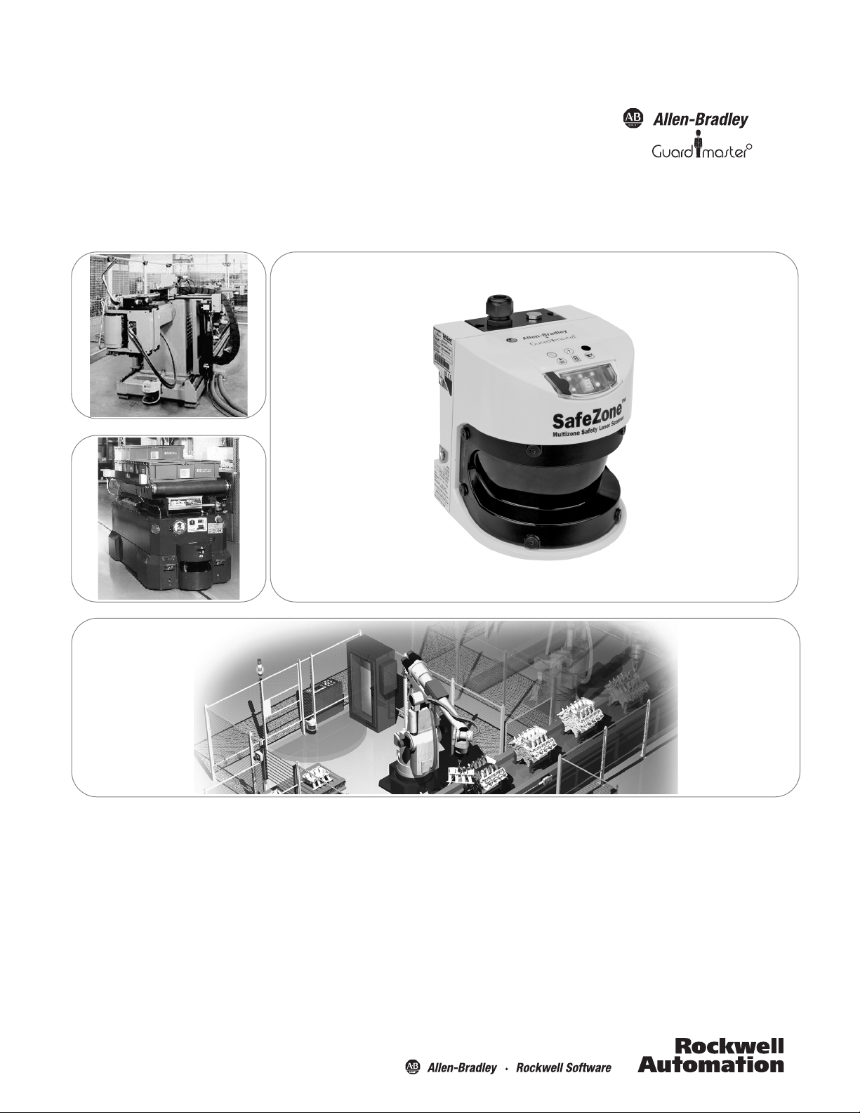
SafeZone Singlezone & Multizone
Safety Laser Scanner
User Manual
R
Page 2
Important User Information
Because of the variety of uses for the products described in this publication, those responsible for the
application and use of this control equipment must satisfy themselves that all necessary steps have been
taken to assure that each application and use meets all performance and safety requirements, including
any applicable laws, regulations, codes and standards.
Reproduction of the contents of this copyrighted publication, in whole or part, without written permission
of Rockwell Automation, is prohibited.
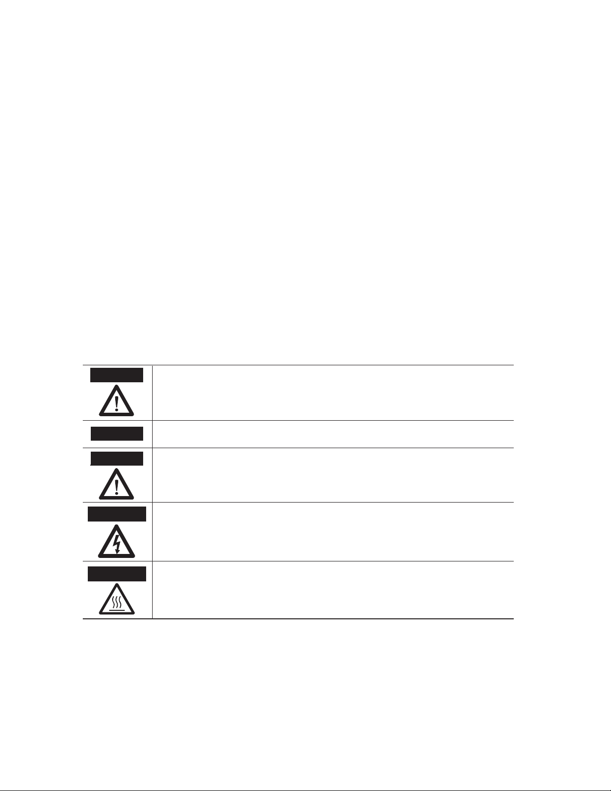
Throughout this manual we use notes to make you aware of safety considerations:
The illustrations, charts, sample programs and layout examples shown in the guide are intended solely for
purposes of example. Since there are many variables and requirements associated with any particular
installation, Rockwell Automation does not assume responsibility or liability (to include intellectual property
liability) for actual use based upon the examples shown in this publication.
Rockwell Automation publication SGI-1.1, Safety Guidelines for the Application, Installation and
Maintenance of Solid-State Control (available from your local Rockwell Automation sales oce), describes
some important dierences between solid-state equipment and electromechanical devices that should be
taken into consideration when applying products such as those described in this publication.
It is recommended that you save this user manual for future use.
Identies information about practices or circumstances that can cause an explosion in
a hazardous environment, which may lead to personal injury or death, property
damage, or economic loss.
Identies information that is critical for successful application and understanding of
the product.
Identies information about practices or circumstances that can lead to personal
injury or death, property damage, or economic loss. Attentions help you identify a
hazard, avoid a hazard, and recognize the consequences.
SHOCK HAZARD
Labels may be on or inside the equipment (for example, drive or motor) to alert people
that dangerous voltage may be present.
BURN HAZARD
Labels may be on or inside the equipment (for example, drive or motor) to alert people
that surfaces may reach dangerous temperatures.
WARNING
IMPORTANT
ATTENTION
Page 3
SafeZone™ Safety Laser Scanner User Manual
R
Related Safety Information
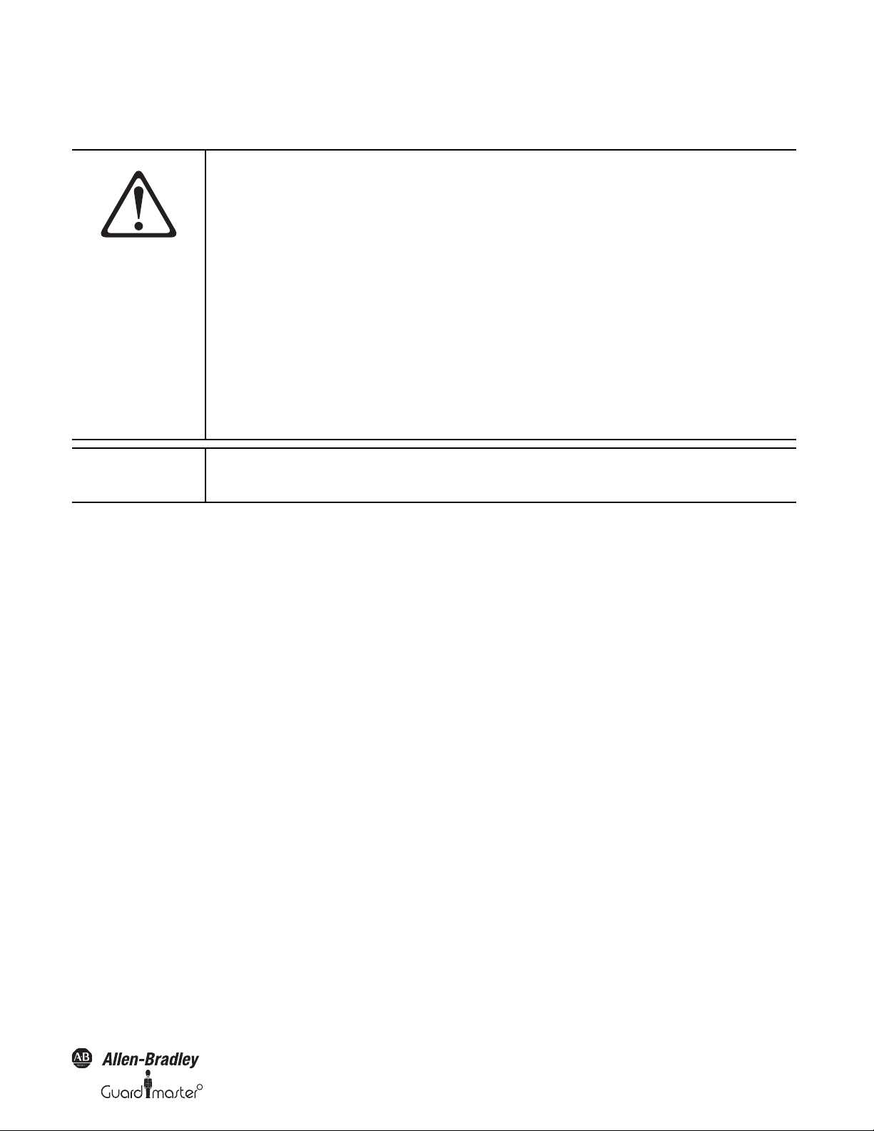
You are responsible for the safety of the entire installed control systems and for meeting all applicable laws, codes, and safety requirements.
AT TE N TI O N
As the installer of this control system, you must be knowledgeable of other applicable standards
pertaining to safety recommendations related to:
Machine Construction
General Electrical
Machine Guarding
Print of operation guards, safety light curtains, mechanical guards, and two-hand control
In addition to local laws and codes, you are responsible for the safety recommendations detailed in
all applicable codes and standards, including:
OSHA Regulations
ANSI Standards
NFPA
CSA
IEC
ISO
IMPORTANT
Rockwell Automation reservest the right to make revisions to these installation instructions and
disclaims liability for all incidental and consequential damages related to the furnishing,
performance and use of this material.
Original instructions
10000073050, July 2011 1
Page 4

SafeZone™ Safety Laser Scanner User Manual
Table of Contents
1 About This Document . . . . . . . . . . . . . . . . . . . . . . . . . . . . . . . . . . . . . . . . . . . . . . . . . . . . . . . . . . . . . . . . . . . . . . . . . . . . . . . . . . . . . . . . . . . . . . . . 3
1.1 Function of this document . . . . . . . . . . . . . . . . . . . . . . . . . . . . . . . . . . . . . . . . . . . . . . . . . . . . . . . . . . . . . . . . . . . . . . . . . . . . . . . . . . . . . . . . . . . 3
1.2 Target group . . . . . . . . . . . . . . . . . . . . . . . . . . . . . . . . . . . . . . . . . . . . . . . . . . . . . . . . . . . . . . . . . . . . . . . . . . . . . . . . . . . . . . . . . . . . . . . . . . . . . 3
1.3 Scope. . . . . . . . . . . . . . . . . . . . . . . . . . . . . . . . . . . . . . . . . . . . . . . . . . . . . . . . . . . . . . . . . . . . . . . . . . . . . . . . . . . . . . . . . . . . . . . . . . . . . . . . . . . 3
1.4 Depth of information . . . . . . . . . . . . . . . . . . . . . . . . . . . . . . . . . . . . . . . . . . . . . . . . . . . . . . . . . . . . . . . . . . . . . . . . . . . . . . . . . . . . . . . . . . . . . . .3
1.5 Abbreviations . . . . . . . . . . . . . . . . . . . . . . . . . . . . . . . . . . . . . . . . . . . . . . . . . . . . . . . . . . . . . . . . . . . . . . . . . . . . . . . . . . . . . . . . . . . . . . . . . . . .3
1.6 Symbols used . . . . . . . . . . . . . . . . . . . . . . . . . . . . . . . . . . . . . . . . . . . . . . . . . . . . . . . . . . . . . . . . . . . . . . . . . . . . . . . . . . . . . . . . . . . . . . . . . . . . 4
2 On Safety. . . . . . . . . . . . . . . . . . . . . . . . . . . . . . . . . . . . . . . . . . . . . . . . . . . . . . . . . . . . . . . . . . . . . . . . . . . . . . . . . . . . . . . . . . . . . . . . . . . . . . . . . . . 4
2.1 Specialist personnel. . . . . . . . . . . . . . . . . . . . . . . . . . . . . . . . . . . . . . . . . . . . . . . . . . . . . . . . . . . . . . . . . . . . . . . . . . . . . . . . . . . . . . . . . . . . . . . . 4
2.2 Device applications . . . . . . . . . . . . . . . . . . . . . . . . . . . . . . . . . . . . . . . . . . . . . . . . . . . . . . . . . . . . . . . . . . . . . . . . . . . . . . . . . . . . . . . . . . . . . . . . 5
2.3 Correct use. . . . . . . . . . . . . . . . . . . . . . . . . . . . . . . . . . . . . . . . . . . . . . . . . . . . . . . . . . . . . . . . . . . . . . . . . . . . . . . . . . . . . . . . . . . . . . . . . . . . . . . 5
2.4 General safety notes and protective measures . . . . . . . . . . . . . . . . . . . . . . . . . . . . . . . . . . . . . . . . . . . . . . . . . . . . . . . . . . . . . . . . . . . . . . . . . . 5
2.5 Environmental protection. . . . . . . . . . . . . . . . . . . . . . . . . . . . . . . . . . . . . . . . . . . . . . . . . . . . . . . . . . . . . . . . . . . . . . . . . . . . . . . . . . . . . . . . . . . . 6
2.6 Applicable directives and standards . . . . . . . . . . . . . . . . . . . . . . . . . . . . . . . . . . . . . . . . . . . . . . . . . . . . . . . . . . . . . . . . . . . . . . . . . . . . . . . . . . . 6
3 Product Description. . . . . . . . . . . . . . . . . . . . . . . . . . . . . . . . . . . . . . . . . . . . . . . . . . . . . . . . . . . . . . . . . . . . . . . . . . . . . . . . . . . . . . . . . . . . . . . . . . 6
3.1 Special features . . . . . . . . . . . . . . . . . . . . . . . . . . . . . . . . . . . . . . . . . . . . . . . . . . . . . . . . . . . . . . . . . . . . . . . . . . . . . . . . . . . . . . . . . . . . . . . . . . 6
3.2 Function . . . . . . . . . . . . . . . . . . . . . . . . . . . . . . . . . . . . . . . . . . . . . . . . . . . . . . . . . . . . . . . . . . . . . . . . . . . . . . . . . . . . . . . . . . . . . . . . . . . . . . . . 6
3.3 Applications . . . . . . . . . . . . . . . . . . . . . . . . . . . . . . . . . . . . . . . . . . . . . . . . . . . . . . . . . . . . . . . . . . . . . . . . . . . . . . . . . . . . . . . . . . . . . . . . . . . . . . 8
3.4 Configurable functions . . . . . . . . . . . . . . . . . . . . . . . . . . . . . . . . . . . . . . . . . . . . . . . . . . . . . . . . . . . . . . . . . . . . . . . . . . . . . . . . . . . . . . . . . . . .10
3.5 Indicators and outputs . . . . . . . . . . . . . . . . . . . . . . . . . . . . . . . . . . . . . . . . . . . . . . . . . . . . . . . . . . . . . . . . . . . . . . . . . . . . . . . . . . . . . . . . . . . .17
4 Installation and Mounting . . . . . . . . . . . . . . . . . . . . . . . . . . . . . . . . . . . . . . . . . . . . . . . . . . . . . . . . . . . . . . . . . . . . . . . . . . . . . . . . . . . . . . . . . . . . 18
4.1 Stationary application in horizontal operation . . . . . . . . . . . . . . . . . . . . . . . . . . . . . . . . . . . . . . . . . . . . . . . . . . . . . . . . . . . . . . . . . . . . . . . . . . . 19
4.2 Stationary vertical operation for access protection . . . . . . . . . . . . . . . . . . . . . . . . . . . . . . . . . . . . . . . . . . . . . . . . . . . . . . . . . . . . . . . . . . . . . .22
4.3 Stationary vertical operation for hazardous point protection . . . . . . . . . . . . . . . . . . . . . . . . . . . . . . . . . . . . . . . . . . . . . . . . . . . . . . . . . . . . . . . . 23
4.4 Mobile applications . . . . . . . . . . . . . . . . . . . . . . . . . . . . . . . . . . . . . . . . . . . . . . . . . . . . . . . . . . . . . . . . . . . . . . . . . . . . . . . . . . . . . . . . . . . . . . . . .24
4.5 Timing for monitoring case switching . . . . . . . . . . . . . . . . . . . . . . . . . . . . . . . . . . . . . . . . . . . . . . . . . . . . . . . . . . . . . . . . . . . . . . . . . . . . . . . . . . .27
4.6 Mounting steps . . . . . . . . . . . . . . . . . . . . . . . . . . . . . . . . . . . . . . . . . . . . . . . . . . . . . . . . . . . . . . . . . . . . . . . . . . . . . . . . . . . . . . . . . . . . . . . . . . . . .29
5 Electrical Installation . . . . . . . . . . . . . . . . . . . . . . . . . . . . . . . . . . . . . . . . . . . . . . . . . . . . . . . . . . . . . . . . . . . . . . . . . . . . . . . . . . . . . . . . . . . . . . . 31
5.1 System connection . . . . . . . . . . . . . . . . . . . . . . . . . . . . . . . . . . . . . . . . . . . . . . . . . . . . . . . . . . . . . . . . . . . . . . . . . . . . . . . . . . . . . . . . . . . . . . .31
5.2 System connector assembly . . . . . . . . . . . . . . . . . . . . . . . . . . . . . . . . . . . . . . . . . . . . . . . . . . . . . . . . . . . . . . . . . . . . . . . . . . . . . . . . . . . . . . . . 32
5.3 Pre-assembled system connectors . . . . . . . . . . . . . . . . . . . . . . . . . . . . . . . . . . . . . . . . . . . . . . . . . . . . . . . . . . . . . . . . . . . . . . . . . . . . . . . . . . 33
6 Application and circuit examples . . . . . . . . . . . . . . . . . . . . . . . . . . . . . . . . . . . . . . . . . . . . . . . . . . . . . . . . . . . . . . . . . . . . . . . . . . . . . . . . . . . . . 33
6.1 Stationary applications . . . . . . . . . . . . . . . . . . . . . . . . . . . . . . . . . . . . . . . . . . . . . . . . . . . . . . . . . . . . . . . . . . . . . . . . . . . . . . . . . . . . . . . . . . . . . . .33
6.2 Mobile applications . . . . . . . . . . . . . . . . . . . . . . . . . . . . . . . . . . . . . . . . . . . . . . . . . . . . . . . . . . . . . . . . . . . . . . . . . . . . . . . . . . . . . . . . . . . . . . . 34
6.3 In tell if ace applications . . . . . . . . . . . . . . . . . . . . . . . . . . . . . . . . . . . . . . . . . . . . . . . . . . . . . . . . . . . . . . . . . . . . . . . . . . . . . . . . . . . . . . . . . . .34
7 Configuration . . . . . . . . . . . . . . . . . . . . . . . . . . . . . . . . . . . . . . . . . . . . . . . . . . . . . . . . . . . . . . . . . . . . . . . . . . . . . . . . . . . . . . . . . . . . . . . . . . . . . .35
7.1 Default delivery status . . . . . . . . . . . . . . . . . . . . . . . . . . . . . . . . . . . . . . . . . . . . . . . . . . . . . . . . . . . . . . . . . . . . . . . . . . . . . . . . . . . . . . . . . . . . . 35
7.2 Preparation of the configuration . . . . . . . . . . . . . . . . . . . . . . . . . . . . . . . . . . . . . . . . . . . . . . . . . . . . . . . . . . . . . . . . . . . . . . . . . . . . . . . . . . . . .35
8 Commissioning . . . . . . . . . . . . . . . . . . . . . . . . . . . . . . . . . . . . . . . . . . . . . . . . . . . . . . . . . . . . . . . . . . . . . . . . . . . . . . . . . . . . . . . . . . . . . . . . . . . . 36
8.1 Initial commissioning . . . . . . . . . . . . . . . . . . . . . . . . . . . . . . . . . . . . . . . . . . . . . . . . . . . . . . . . . . . . . . . . . . . . . . . . . . . . . . . . . . . . . . . . . . . . . .36
8.2 Test notes . . . . . . . . . . . . . . . . . . . . . . . . . . . . . . . . . . . . . . . . . . . . . . . . . . . . . . . . . . . . . . . . . . . . . . . . . . . . . . . . . . . . . . . . . . . . . . . . . . . . . .36
8.3 Re-commissioning . . . . . . . . . . . . . . . . . . . . . . . . . . . . . . . . . . . . . . . . . . . . . . . . . . . . . . . . . . . . . . . . . . . . . . . . . . . . . . . . . . . . . . . . . . . . . . . 37
9 Care and Maintenance . . . . . . . . . . . . . . . . . . . . . . . . . . . . . . . . . . . . . . . . . . . . . . . . . . . . . . . . . . . . . . . . . . . . . . . . . . . . . . . . . . . . . . . . . . . . . . 38
9.1 Cleaning the front screen . . . . . . . . . . . . . . . . . . . . . . . . . . . . . . . . . . . . . . . . . . . . . . . . . . . . . . . . . . . . . . . . . . . . . . . . . . . . . . . . . . . . . . . . . . 38
9.2 Replacing the front screen . . . . . . . . . . . . . . . . . . . . . . . . . . . . . . . . . . . . . . . . . . . . . . . . . . . . . . . . . . . . . . . . . . . . . . . . . . . . . . . . . . . . . . . . .38
9.3 Replacing the I/O module . . . . . . . . . . . . . . . . . . . . . . . . . . . . . . . . . . . . . . . . . . . . . . . . . . . . . . . . . . . . . . . . . . . . . . . . . . . . . . . . . . . . . . . . . .39
10 Diagnostics . . . . . . . . . . . . . . . . . . . . . . . . . . . . . . . . . . . . . . . . . . . . . . . . . . . . . . . . . . . . . . . . . . . . . . . . . . . . . . . . . . . . . . . . . . . . . . . . . . . . . . 40
10.1 In the event of faults or errors . . . . . . . . . . . . . . . . . . . . . . . . . . . . . . . . . . . . . . . . . . . . . . . . . . . . . . . . . . . . . . . . . . . . . . . . . . . . . . . . . . . . . .40
10.2 Rockwell Support . . . . . . . . . . . . . . . . . . . . . . . . . . . . . . . . . . . . . . . . . . . . . . . . . . . . . . . . . . . . . . . . . . . . . . . . . . . . . . . . . . . . . . . . . . . . . . . 40
10.3 Indications and error messages . . . . . . . . . . . . . . . . . . . . . . . . . . . . . . . . . . . . . . . . . . . . . . . . . . . . . . . . . . . . . . . . . . . . . . . . . . . . . . . . . . . .40
10.4 Errors displayed by the 7-segment display . . . . . . . . . . . . . . . . . . . . . . . . . . . . . . . . . . . . . . . . . . . . . . . . . . . . . . . . . . . . . . . . . . . . . . . . . . . . 41
10.5 Extended diagnostics . . . . . . . . . . . . . . . . . . . . . . . . . . . . . . . . . . . . . . . . . . . . . . . . . . . . . . . . . . . . . . . . . . . . . . . . . . . . . . . . . . . . . . . . . . . . 42
11 Technical specifications . . . . . . . . . . . . . . . . . . . . . . . . . . . . . . . . . . . . . . . . . . . . . . . . . . . . . . . . . . . . . . . . . . . . . . . . . . . . . . . . . . . . . . . . . . . . 42
11.1 Characteristics . . . . . . . . . . . . . . . . . . . . . . . . . . . . . . . . . . . . . . . . . . . . . . . . . . . . . . . . . . . . . . . . . . . . . . . . . . . . . . . . . . . . . . . . . . . . . . . . . 42
11.2 OSSD response times. . . . . . . . . . . . . . . . . . . . . . . . . . . . . . . . . . . . . . . . . . . . . . . . . . . . . . . . . . . . . . . . . . . . . . . . . . . . . . . . . . . . . . . . . . . . 42
11.3 Timing behavior of the OSSDs . . . . . . . . . . . . . . . . . . . . . . . . . . . . . . . . . . . . . . . . . . . . . . . . . . . . . . . . . . . . . . . . . . . . . . . . . . . . . . . . . . . . .43
11.4 Data sheet . . . . . . . . . . . . . . . . . . . . . . . . . . . . . . . . . . . . . . . . . . . . . . . . . . . . . . . . . . . . . . . . . . . . . . . . . . . . . . . . . . . . . . . . . . . . . . . . . . . . .45
11.5 Dimensional drawings . . . . . . . . . . . . . . . . . . . . . . . . . . . . . . . . . . . . . . . . . . . . . . . . . . . . . . . . . . . . . . . . . . . . . . . . . . . . . . . . . . . . . . . . . . . .50
12 Ordering information . . . . . . . . . . . . . . . . . . . . . . . . . . . . . . . . . . . . . . . . . . . . . . . . . . . . . . . . . . . . . . . . . . . . . . . . . . . . . . . . . . . . . . . . . . . . . . . 52
12.1 Delivery . . . . . . . . . . . . . . . . . . . . . . . . . . . . . . . . . . . . . . . . . . . . . . . . . . . . . . . . . . . . . . . . . . . . . . . . . . . . . . . . . . . . . . . . . . . . . . . . . . . . . . .52
12.2 Accessories/spare parts . . . . . . . . . . . . . . . . . . . . . . . . . . . . . . . . . . . . . . . . . . . . . . . . . . . . . . . . . . . . . . . . . . . . . . . . . . . . . . . . . . . . . . . . . .53
13 Annex . . . . . . . . . . . . . . . . . . . . . . . . . . . . . . . . . . . . . . . . . . . . . . . . . . . . . . . . . . . . . . . . . . . . . . . . . . . . . . . . . . . . . . . . . . . . . . . . . . . . . . . 54
13.1 Declaration of conformity . . . . . . . . . . . . . . . . . . . . . . . . . . . . . . . . . . . . . . . . . . . . . . . . . . . . . . . . . . . . . . . . . . . . . . . . . . . . . . . . . . . . . . . .
13.2 Manufacturer’s checklist . . . . . . . . . . . . . . . . . . . . . . . . . . . . . . . . . . . . . . . . . . . . . . . . . . . . . . . . . . . . . . . . . . . . . . . . . . . . . . . . . . . . . . . . . . 54
13.3 Glossary . . . . . . . . . . . . . . . . . . . . . . . . . . . . . . . . . . . . . . . . . . . . . . . . . . . . . . . . . . . . . . . . . . . . . . . . . . . . . . . . . . . . . . . . . . . . . . . . . . . . . .55
2 10000075030, July 2011
Original instructions
R
Page 5

R
SafeZone™ Safety Laser Scanner User Manual
Section 1 — About this Document
Please read this section carefully before working with this documentation
and the SafeZone safety laser scanner.
1.1 Function of this document
These operating instructions are designed to address the technical
personnel of the machine manufacturer or the machine operator in
regards to correct mounting, electrical installation, commissioning,
operation and maintenance of the SafeZone safety laser scanners.
These operating instructions do not provide instructions for operating
the machine, the system or the vehicle on which the safety laser scanner
is, or will be, integrated. Information on this is to be found in the
appropriate operating instructions of the machine, the system or the
vehicle.
1.2 Target group
These operating instructions are addressed to planning engineers,
developers and the operators of machines and systems which are to be
protected by one or several SafeZone safety laser scanners. They also
address people who integrate the SafeZone safety laser scanners into a
machine, a system or a vehicle, initialize its use, or who are in charge of
servicing and maintaining the device.
1.3 Scope
IMPORTANT
These operating instructions are only
applicable to the SafeZone safety laser
scanner.
Recommendation
Users should refer to the
Allen-Bradley
Guardmaster home page on the
Internet at: www.ab.com/safety
Here users will find information on:
• Application examples
• A list of frequently asked questions regarding the SafeZone safety
laser scanners
• These operating instructions in different languages for viewing and
printing
.
1.5 Abbreviations
Automated guided vehic le
AGV
ANSI
AWG
ESPE
FPLC
OSSD
American National Standards Institute
American Wire Gauge = standardization and classification of wires and
cables by type, diameter etc.
Safety Configuration and Diagnostic Software
SCD
External device monitoring
EDM
Electrostatic discharge
ESD
Electro-sensitive protective equipment
Fail-safe programmable logic controller
Output signal switching device = signal output of the protective device
that is used to stop the dangerous movement
Robotic Industries Association
RIA
For the configuration and diagnostics of these devices you require SCD
software version 2.23 or higher. To check the version of the software, on
the ? menu select Module info...
1.4 Depth of information
These operating instructions contain information on the SafeZone safety
laser scanner:
• installation and
mounting
• electrical installation • part numbers
• commissioning and
configuration
• care and maintenance • conformity and approval
Planning and using protective devices such as the SafeZone safety laser
scanner also requires specific technical skills that are not detailed in this
documentation.
When operating the SafeZone safety laser scanner, the national, local and
statutory rules and regulations must be observed.
• fault, error diagnosis and
troubleshooting
• accessories
Original instructions
10000073050, July 2011 3
Page 6
SafeZone™ Safety Laser Scanner User Manual
,
.
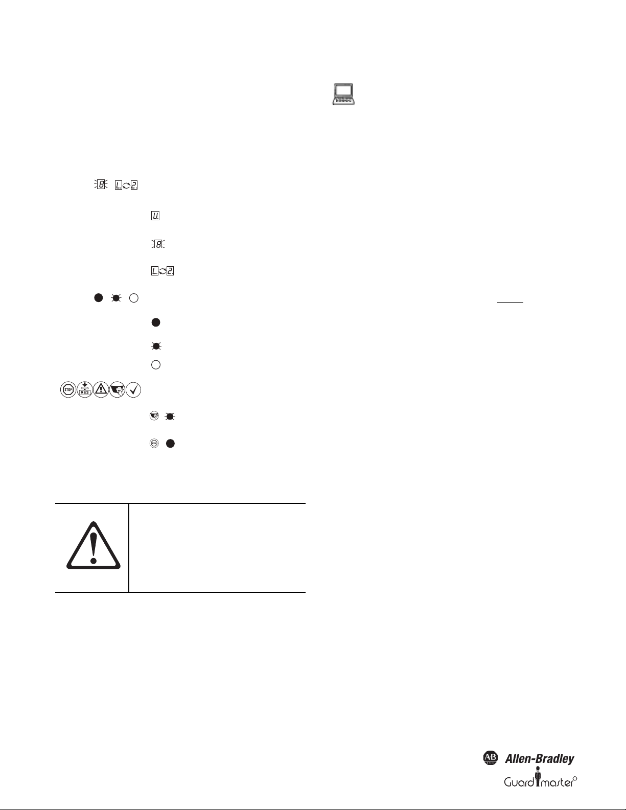
1.6 Symbols used
Recommendation Recommendations are designed to give you
some assistance in your decision-making
process with respect to a certain function or
a technical measure.
Note Refer to notes for special features of the
device.
Display indicators show the status of the 7segment display on the SafeZone safety laser
scanner:
Constant indication of
characters, e.g. U
Flashing indication of
characters, e.g. 8
Alternating indication of
characters, e.g. L and 2
LED symbols describe the status an LED:
The LED is constantly
illuminated.
The LED is flashing.
The LED is off.
These symbols identify which LED is
described.
The “Error/Contamination”
LED is flashing.
The “OSSDs deactivated” LED
is constantly illuminated
²Take acti on… Instructions for taking action are shown by
an arrow. Read carefully and follow the
instructions for action.
AT TE N TI O N
Indicates an actual or potential risk or
health hazard. Observation and
implementation of the instruction will
protect you from accidents.
Read each one carefully and follow the
instructions that are associated with
each topic.
Software notes show the location in the SCD software
where you can make the appropriate settings and
adjustments. In the SCD software on the View menu,
Dialog Box, select the item File Cards to go straight to the
stated dialog fields. Alternatively, the software wizard will
guide you through the appropriate setting.
The term “dangerous state”
The dangerous state (standard term) of the machine is
always shown in the drawings and diagrams of this
document as a movement of a machine part. In
practical operation, there may be a number of
different dangerous states:
• Machine movements
•Vehicle movements
• Electrical conductors
• Visible or invisible radiation
• A combination of several risks and hazards
Section 2 —On Safety
This section deals with your own safety and the safety of the equipment
operators.
Please read this section carefully before working with the SafeZone
safety laser scanner or with the machine protected by the SafeZone
multizone safety laser scanner.
2.1 Specialist personnel
The SafeZone safety laser scanner must be installed, connected,
commissioned and serviced only by specialist personnel. Specialist
personnel are defined as persons who
• Due to their specialist training and experience have adequate knowledge
of the power-driven equipment to be checked
and
• Who have been instructed by the responsible machine operator in the
operation of the machine and the current valid safety guidelines
and
Are sufficiently familiar with the applicable official health and safety
regulations, directives and generally recognized engineering practice (e.g.
DIN standards, VDE stipulations, engineering regulations from other
EC member states) that they can assess the work safety aspects of the
power-driven equipment
and
• Who have access to the operating instructions and who have read
them.
4 10000073050, July 2011
Original instructions
R
Page 7
R
SafeZone™ Safety Laser Scanner User Manual
As a rule these are specialist personnel from the ESPE manufacturer or also
those persons who have been appropriately trained at the ESPE
manufacturer, are primarily involved in checking ESPE and are allocated
the task by the organization operating the ESPE.
2.2 Device applications
The SafeZone safety laser scanner is used to protect persons and
equipment. It is intended to be used to monitor hazardous areas indoors.
The SafeZone safety laser scanner is not intended for outdoor use.
The SafeZone safety laser scanner cannot provide protection from flying
parts or from emitted radiation.
The SafeZone safety laser scanner complies with the requirements in the
standard on the radiated emissions as defined for class A (industrial
application). It may cause radio interference in residential areas.
The safety level of the SafeZone safety laser scanner corresponds to
Category 3 in compliance with EN 954-1 and ISO EN 13849-1, SIL CL
2.
The SafeZone safety laser scanner is suitable for:
• Hazardous area protection
• Hazardous point protection
• Access protection
• Vehicle protection
IMPORTANT
Depending on the application, other
protective devices and measures may
be required in addition to the safety
laser scanner.
2.3 Correct use
The SafeZone safety laser scanner must only be used as defined in
Section 2.2 “Device Applications” above. It must only be used by
qualified personnel on the machine where it has been installed and
initialized by specialist personnel in accordance with these operating
instructions. It is only permitted to be used on machines on which the
dangerous state can be stopped immediately by the SafeZone safety laser
scanner and/or it is possible to prevent the machine being placed in
operation.
Note: If the device is used for any other purposes or modified in any
way—also during mounting and installation—any warranty claim
against Rockwell Automation shall become void.
2.4 General safety notes and protective
measures
NOTICE
LASER CLASS I
Complies with 21 CFR 1040.10 and 10401.1
Complies with DIN EN 60825:2001
AT T EN T IO N
• This device meets the norms of OSHA 21 CFR 1040.10 as well as IEC
60825:2001. “Caution: use of controls or adjustments or performance of
procedures other than those specified herein may result in hazardous
radiation exposure.”
• During the mounting, installation and usage of the SafeZone safety
laser scanner, observe the standards and directives applicable in your
country. There is an overview of important regulations in Section 2.6
“Applicable directives and standards” on page 6.
• National/international rules and regulations apply to the installation,
commissioning, use and periodic technical inspections of the SafeZone
safety laser scanner, in particular - Machine Directive 98/37/EC
- Work Equipment Directive 89/655/EEC
- The work safety regulations/safety rules
- Other relevant health and safety regulations
• Manufacturers and users of the machine on which the SafeZone
safety laser scanner is used are responsible for obtaining and observing
all applicable safety regulations and rules.
• The test notes (see Section 8 “Commissioning” on page 36) in these
operating instructions (e.g. on use, mounting, installation or
integration into the machine controller) must be observed. Changes
to the configuration of the devices can degrade the protective
function. After every change to the configuration you must check the
effectiveness of the protective device. The person who makes the
change is also responsible for the correct protective function of the
device. When making configuration changes, always use the password
hierarchy provided by Rockwell Automation to ensure that only
authorized persons make changes to the configuration.
• Tests must be carried out by specialist personnel or specially qualified
and authorized personnel and must be recorded and documented to
ensure that the tests can be reconstructed and retraced at any time.
• Operating instructions must be made available to the operator of the
machine where the SafeZone safety laser scanner is used. The machine
operator is to be instructed in the use of the device by specialist
personnel and must be instructed to read the operating instructions.
The SafeZone safety laser scanner is of
laser safety class I (eye safe).
Take appropriate measures for working
with laser scanners.
Read safety notes.
Observe the following statements in
order to ensure the correct use of the
SafeZone multizone safety laser scanner.
Original instructions
10000073050, July 2011 5
Page 8
SafeZone™ Safety Laser Scanner User Manual
• Suitable power supplies are available from Rockwell Automation. The
external voltage supply of this device must be capable of buffering brief
mains voltage failures of 20 ms as specified in EN 60204.
• Included in this document is a checklist for checking by the
manufacturer and OEM (see Section 13.1 “Manufacturer’s checklist” on
page 54). This checklist should be used when checking the equipment
that is protected with the SafeZone multizone safety laser scanner.
2.5 Environmental protection
The SafeZone safety laser scanner is constructed in such a way as to
minimize adverse affects to the environment. It uses only a minimum of
power and natural resources.
Disposal
Always dispose of unserviceable or irreparable devices in compliance
with local/national rules and regulations on waste disposal.
2.6 Applicable directives and standards
Important directives and standards, valid for the use of opto-electronic
safety systems in Europe, are listed below. Further regulations may be of
importance to you, depending on the type of use. Users can obtain
further information of machine-specific standards from national
institutions (e.g. DIN, BSI, ANSI, OSHA, etc.), the authorities or
applicable trade association.
• Machine tools for manufacturing systems/cells (ANSI B11.20)
• Safety requirements for Industrial Robots and Robot Systems
(ANSI/RIA R15.06)
• Safety Standard for guided industrial vehicles and automated functions
of named industrial vehicles (ANSI B56.5)
IMPORTANT
The SafeZone safety laser scanner
meets the requirement of “Control
Reliability.”
Section 3 — Product Description
AT T EN T IO N
This section provides information on the special features and properties
of the SafeZone multizone safety laser scanner. It describes the structure
and the operating principle of the device, in particular the different
operating modes.
Please read this section before
mounting, installing and
commissioning the device.
Because this device is used to monitor
a hazardous area, it is important to
read this entire section before
mounting and installing the device.
Application and installation of safety systems
Machine Directive 98/37/EC, e.g.:
• Safety of machinery—Basic concepts, general principles for design
(EN 292)
• Industrial automation systems—Safety of integrated manufacturing
systems—Basic requirements (ISO 11161)
• Safety of machinery—Electrical equipment of machines—Part 1:
General requirements (IEC/EN 60204)
• Safety of machinery. Safety distances to prevent danger zones being
reached by the upper limbs (EN 294, IEC 13852)
• Safety requirements for robots (EN 775, ISO 10218)
• Safety of industrial trucks. Driverless trucks and their systems (DIN/
EN 1525)
• Safety of machinery—The positioning of protective equipment in
respect of approach speeds of parts of the human body (EN 999, ISO
13855)
• Safe ty of ma chiner y—Principles for risk assessment (EN 1050, ISO 14121)
• Safety of machinery—Safety-related parts of control systems~Part 1:
General principles for design (EN 954 part 1 and part 2, ISO 13849
part 1 and part 2)
• Safety of machines—Electro-sensitive protective equipment—Part 1:
General requirements (IEC/EN 61496-1) as well as pa rt 3: Par ticular
requirements for Active Opto-electronic Protective Devices responsive
to Diffuse Reflection (AOPDDR) (IEC/EN 61496-3)
• Performance Criteria for Safeguarding (ANSI B11.19)
3.1 Special features
• Scanning ranges of four and five meters
• 190° scanning angle
• Singlezone has a single field set and multizone has up to four field sets
• The contour of the protective safety field can be monitored (contour
change can e.g. be the opening of a door to the outside)
• Integrated external device monitoring (EDM)
• Integrated restart interlock/restart interlock delay for which
parameters can be set
• Status display with LEDs and seven-segment display
• Simple replacement of the I/O module (in this way the functionality
can be easily enhanced)
• Selection of either 60 ms minimum or 120 ms maximum response
time
• Configuration using PC or notebook with SCD software
• Configuration memory in the system plug. Down times are shortened
by the easy replacement of the SafeZone safety laser scanner
• Increased immunity to external light and dust
3.2 Function
The SafeZone safety laser scanner only operates correctly as a protective
device if the following conditions are met:
• The control of the machine, system or vehicle must be electrical.
6 10000073050, July 2011
Original instructions
R
Page 9
R
SafeZone™ Safety Laser Scanner User Manual
• It must be possible to transfer the dangerous state of the machine, the
equipment or the vehicle to a safe state at any time using the OSSDs
on the SafeZone safety laser scanner after integration in the
controller.
• The SafeZone safety laser scanner must be mounted and configured
such that it detects objects as they enter the hazardous area (see
Section 4 “Installation and mounting” on page 18).
3.2.1 Principles of operation
The SafeZone safety laser scanner is an optical sensor that scans its
surroundings in two dimensions using infrared laser beams. It is used to
monitor a hazardous area on a machine or a vehicle.
R
S
Δt
S
R
S – Δt
The SafeZone safety laser scanner uses light pulses precisely radiated in
specific directions. Thus the laser scanner does not continuously cover
the area to be monitored. In this way resolutions of between 30 mm and
150 mm are achieved.
Due to its active scanning principle, the SafeZone safety laser scanner
does not require receivers or reflectors. This has the following
advantages:
• Ease of installation.
• You can easily adapt the monitored area to the hazardous area on a
machine.
• In comparison with contact sensors, there is less wear when electrosensitive scanning is used.
3.2.2 Field set comprised of protective safety field and
warning field
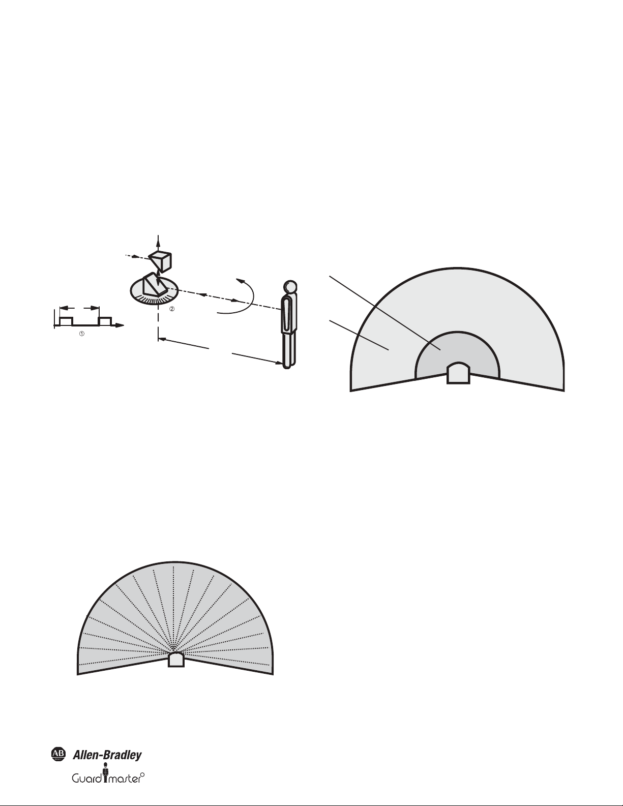
Figure 1: Principle of operation, time of flight measurement by the
SafeZone safety laser scanner
The SafeZone safety laser scanner works on the principle of time of flight
measurement . It sends out very short pulses of infrared light (S). At
the same time an “electronic stopwatch” is started. When the light is
reflected off of an object, it is received by the safety laser scanner (E).
From the time between sending and receiving (
Δt) the SafeZone
multizone safety laser scanner calculates the distance to the object.
In the SafeZone safety laser scanner there is also a mirror rotating at
constant speed that deflects the light pulses such that they cover an arc
of 190°. By determining the angle of rotation of the mirror, the SafeZone
safety laser scanner determines the direction of the object.
From the measured distance and the direction of the object, the safety
laser scanner determines the exact position of the object.
Figure 3: Protective safety field and warning field
The protective safety field secures the hazardous area on a machine or
vehicle. As soon as the safety laser scanner detects an object in the
protective safety field, it switches the OSSDs to the off status and thus
initiates the shutdown of the machine or stop of the vehicle.
You can define the warning field such that the safety laser scanner detects
an object before the actual hazardous area and e.g. triggers a warning signal.
The protective safety field and warning field form a pair, the so-called
field set. With the aid of the SCD you can configure these field sets and
transfer them to the SafeZone safety laser scanner. If the area to be
monitored changes, then you can re-configure the SafeZone safety laser
scanner in software without additional mounting effort.
The SafeZone Singlezone has a single configurable field set. The
SafeZone Multizone has up to four configurable field sets. The SafeZone
Multizone allows switching between field sets if the monitoring situation
changes (see Section 3.2.3 “Monitoring cases” below).
3.2.3 Monitoring cases
Four monitoring cases can be defined in the SafeZone multizone and
selected during operation using static control input. Each monitoring
case includes:
Figure 2: Principle of operation of the SafeZone safety laser
scanner—light pulses
Original instructions
• The input conditions, the so-called control signals, that control the
activation of the monitoring case.
• A field set, comprising protective safety field and warning field.
• If necessary, a simultaneous field set without separate outputs.
10000073050, July 2011 7
Page 10
SafeZone™ Safety Laser Scanner User Manual
Protective safety field case 1
Protective safety field case 2
Warnin
g
field
System plug
I/O module
Sensor head
Warning fiel
Protective safety field
Protective safety field
and warning field
monitoring case 2
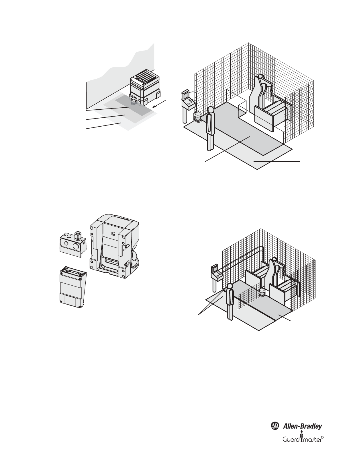
Figure 4: SafeZone multizone safety laser scanner with two defined
monitoring cases on an AGV
3.2.4 Device components
The SafeZone safety laser scanner comprises three components:
• The sensor head with the opto-electronic acquisition system
• The I/O module, this defines the functionality of the SafeZone safety
laser scanner
• The system plug with the configuration memory (the system plug
contains all electrical connections)
Figure 6: Hazardous area protection with one monitored area
Hazardous area protection with multiple monitored areas
(position-related protective safety field switching)
Using the SafeZone safety laser scanner, you can define up to four
monitoring cases to match the protective safety field and warning field to
the situation on the machine and to monitor chang ing hazardous areas~e.g.
during different machine production phases~depending on the situation.
Figure 5: Sensor head, I/O module and system plug
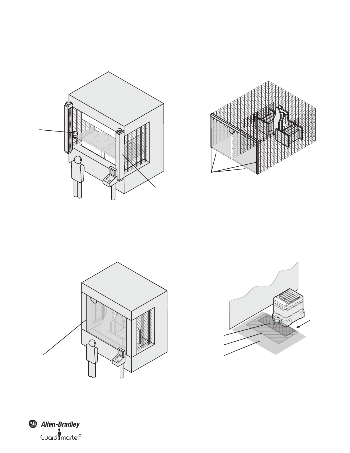
3.3 Applications
3.3.1 Stationary applications
Hazardous area protection
On dangerous stationary machines, the SafeZone safety laser scanner
switches the output signal switching devices (OSSDs) to the off status if
the protective safety field is interrupted. The SafeZone safety laser
scanner initiates the shutdown of the machine or the shutdown of the
dangerous state.
8 10000073050, July 2011
and warning field
monitoring case 1
Figure 7: Hazardous area protection with multiple monitored areas
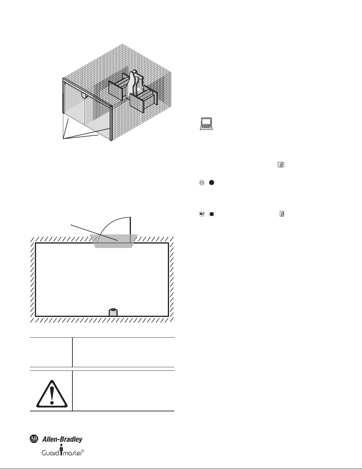
Interior protection
On large machines the SafeZone safety laser scanner can be used to
protect the interior. The machine can only be restarted if the SafeZone
safety laser scanner does not detect any object in the protective safety
field. This is particularly important for interiors that can only be seen
with difficulty from the outside, or cannot be seen at all.
Original instructions
R
Page 11
R
SafeZone™ Safety Laser Scanner User Manual
Contours of the machine
opening as reference
Contours on the floor and the
side walls as reference
In this application, the SafeZone safety laser scanner only has a secondary
protective function. The primary safety function that stops the dangerous
movement is provided in the example by a light curtain , while the
SafeZone safety laser scanner monitors the restarting of the machine.
Figure 8: Interior protection
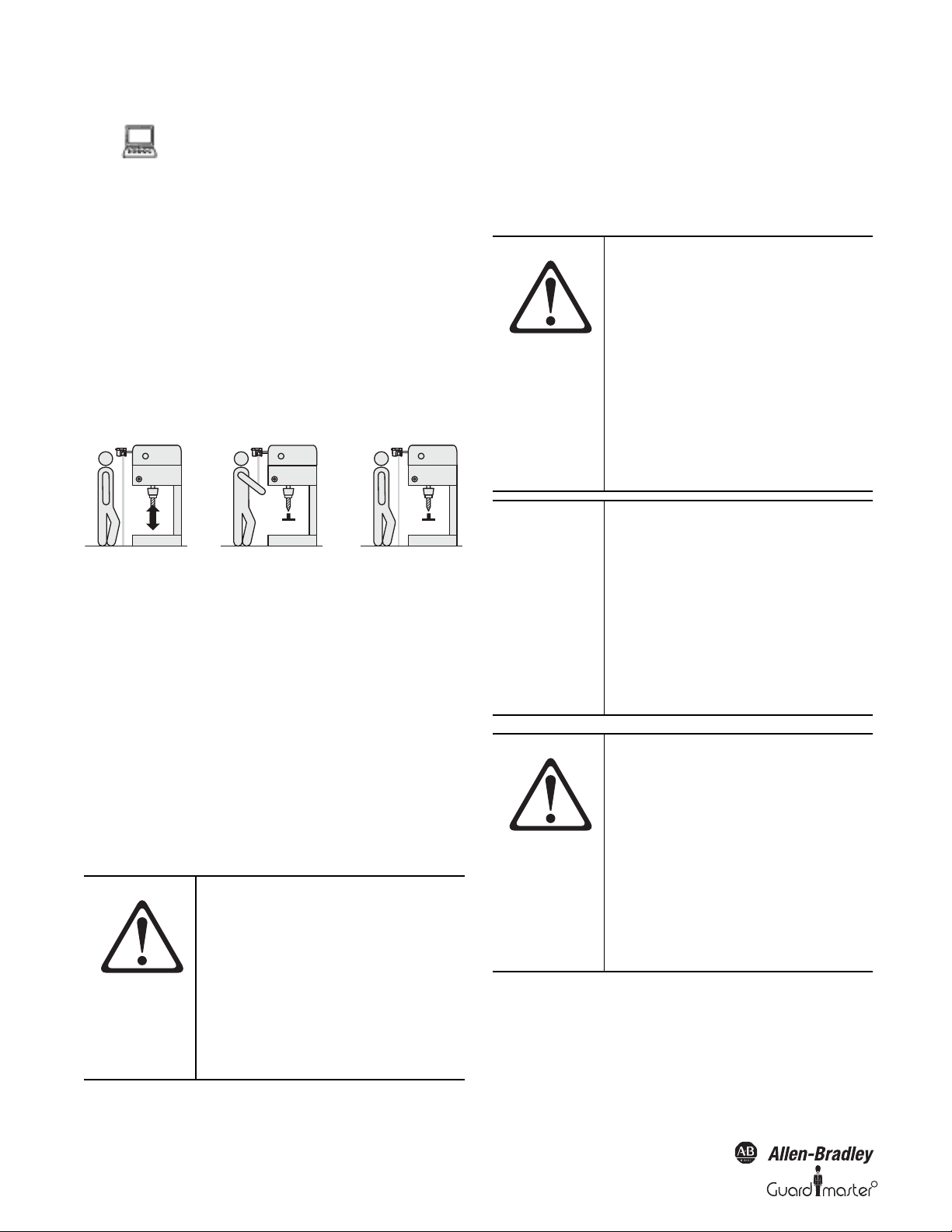
Hazardous point protection (vertical protection)
The SafeZone safety laser scanner can also be used vertically. Mounting in this
way requires less space on the machine or equipment. Hazardous point
protection is necessary if the operator is near the dangerous state of the
machine. Hand protection must be configured to protect the hazardous
point.
Access protection (vertical protection)
You can also use the SafeZone safety laser scanner vertically for access
protection. Access protection can be used when the access to the machine
can be defined by physical means. With access protection the SafeZone
safety laser scanner detects the entry of a person.
Figure 10: Access protection
3.3.2 Mobile applications
The SafeZone safety laser scanner can be used both on manually
controlled vehicles, e.g. fork lift trucks, and also on automated guided
vehicles (AGV) or trolleys.
You can use the SafeZone safety laser scanner on vehicles, e.g. to protect
the route of a vehicle through a factory building. If there is a person or an
obstacle in the hazardous area, the SafeZone safety laser scanner ensures
that the vehicle reduces speed and stops if necessary.
Figure 9: Protecting hazardous points
Protective safety field case 1
Protective safety field case 2
Warning field
Figure 11: Field switching
Original instructions
10000073050, July 2011 9
Page 12
SafeZone™ Safety Laser Scanner User Manual
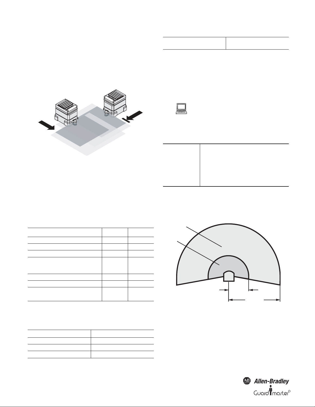
3.3.3 Other applications (not for personnel protection)
Along with safety-related applications, you can also use the SafeZone safety
laser scanner for applications in which people do not need to be protected.
Collision protection
Along with people, you can also protect vehicles from colliding with
other objects.
Figure 12: Collision protection
As soon as vehicle reaches the warning field of vehicle , vehicle slows
down. When vehicle reaches the protective safety field of vehicle ,
vehicle stops.
Currently there are two SafeZone variants offered. The SafeZone
Singlezone is offered with a 4 meter protective safety field range and
Single field set (Warning and protective safety fields) and the SafeZone
Multizone is offered with a 5 meter protective safety field and up to four
configurable field sets.
Table 1: Functions of the I/O module
Functions
Pairs of output signal switching devices (OSSDs)
External device monitoring (EDM)
Restart interlock/delay
Application diagnostic output (warning field
interrupted, control switch, restart or reset pressed,
error/contamination
Switchable field sets
Programmable monitoring cases
Static control inputs for switching between the
monitoring cases (complementary or 1-of-n)
SafeZone SafeZone
11
Yes Yes
Yes Yes
33
41
41
2—
3.3.4 Possible applications for the SafeZone multizone
safety laser scanner variants
Protection of an automated guided vehicle AGV
with bi-directional travel
In each direction of travel up to four switchable
field sets
3.4 Configurable functions
3.4.1 Field sets
Configuring the protective safety field and warning field
With the aid of the SCD software you can configure
the field set, which comprises a protective safety field
and a warning field. During this process you
configure the shape and size of the protective safety
field and the warning field. You can realize any field
shape required.
Device symbol SafeZone safety laser scanner, context
menu Edit field sets....
IMPORTANT
The area to be monitored is scanned
radially by the SafeZone safety laser
scanner. The SafeZone safety laser
scanner cannot “see around a corner.”
The area behind objects that are in the
area to be monitored (pillars, columns,
etc.) can thus not be monitored.
• The protective safety fields () can cover up to 190° and have a radius
of up to 4 or 5 m.
• The warning fields () can cover up to 190° and have a radius of up to
49 m. Detection is dependent on the reflectivity (e.g. objects with a
reflectivity of 20% can be detected in a radius of up to 20 m).
5 M
E.g. 20 m
at 20%
reflectivity
Figure 13: Protective safety field and warning field
Table 2: Possible applications for the I/O modules
Typical Application Functionality Required
Protection of a robot insertion station One field set
Protection of a pipe bending machine Up to four switchable field sets
Protection of a material processing system‘ Up to four switchable field sets
10 10000073050, July 2011
Original instructions
R
Page 13
R
SafeZone™ Safety Laser Scanner User Manual
Protective safety field
2
1
AT TE N TI O N
Check the protective safety field
configuration.
Prior to commissioning the machine or
vehicle, check the configuration of the
protective safety fields using the
instructions in Section 8
“Commissioning” (page 36) and using
the checklist (page 54).
Protective safety field suggested by the safety laser scanner
You can also have the SCD software suggest a protective safety field. The
safety laser scanner scans the visible room contour several times. During this
process possible measurement errors are taken into account. From the data
obtained in this way the SCD software determines the contour of the
protective safety field.
You can obtain the suggestion for the protective
safety field in the field set editor in the SCD
software: Device symbol SafeZone safety laser
scanner, command Edit field sets.... In the field set
editor window that opens, Suggest protective safety
field button.
The size determined for the protective safety field is:
• As large as the visible room contour.
• In those places where there is no room contour
within the scanning range, as large as the
maximum scanning range of the safety laser
scanner (4 or 5 m).
IMPORTANT
The measurement error tolerances of
the SafeZone safety laser scanner are
automatically subtracted from the
protective safety field suggested. As a
result the protective safety field is
slightly smaller than the surface
acquired.
room contour (less the measurement tolerances). In those places where
the room contour is larger than the nominal scanning range , the
protective safety field corresponds to the nominal scanning range (4 or
5m).
WAR NIN G
Check the protective safety field
suggested.
The scanner cannot calculate the safety
distance necessary for your
application. Calculate the safety
distance based on the description in
Section 4 “Installation and mounting”
on page 18. Prior to commissioning the
machine or vehicle, check the
configuration of the protective safety
fields using the instructions in Section
8 “Commissioning” on page 36 and
using the checklist on page 54.
3.4.2 Application
With the SCD software you can configure the
SafeZone safety laser scanner for the required
application. For each application you first set the
resolution (device symbol SafeZone safety laser
scanner system, context menu Configuration draft,
Edit..., file card Application):
• Possible resolution for stationary applications:
30 mm (hand detection with smaller safety distance)
- 40 mm (hand detection with larger safety distance)
- 50 mm (leg detection with smaller protective safety field
size)
- 70 mm (leg detection with larger protective safety field
size)
- 150 mm (body detection)
• Possible resolution for mobile application:
- 70 mm (leg detection)
IMPORTANT
For mobile applications a resolution of
only 70 mm is required for leg
detection, as a lower resolution is
sufficient for the detection of a human
leg due to the movement of the
vehicle.
Figure 14: Reading protective safety field and warning field
In those places at which the room contour is smaller than the nominal
scanning range (e.g. at ), the protective safety field corresponds to the
Original instructions
10000073050, July 2011 11
Page 14
SafeZone™ Safety Laser Scanner User Manual
The maximum protective safety field range is dependent on the
resolution selected, and the basic response time for the application is in
turn dependent of the protective safety field range. The following tables
show the values that can be configured:
Table 3: Maximum protective safety field range—SafeZone
multizone 5 m range
Application 60 ms Basic Response Time 120 ms Basic Response Time
Stationary
30 mm (hand detection)
40 mm (hand detection)
50 mm (leg detection)
70 mm (leg detection)
150 mm (body detection)
Mobile
70 mm (leg detection)
1.90 m 2.80 m
2.60 m 3.80 m
3.30 m 4.80 m
4.70 m 5 m
5 m 5 m
4.7 m 5 m
Table 3B: Maximum protective safety field range—SafeZone
singlezone 4 m range
Application 60 ms Basic Response Time 120 ms Basic Response Time
Stationary
30 mm (hand detection)
40 mm (arm detection)
50 mm (leg detection)
70 mm (leg detection)
150 mm (whole body
Mobile
70 mm (leg detection)
IMPORTANT
If the application involves multiple
1.90 m 2.80 m
2.60 m 3.80 m
3.30 m 4.00 m
4.00 m 4.00 m
4.00 m 4.00 m
4.00 m 4.00 m
sampling, that basic response time
may require added supplements. Refer
to Section 11.2 “OSSD response times”
(page 42) for more information.
Figure 15: Schematic diagram of contour as reference
For contour monitoring you define part of the protective safety field as
a contour segment . Within the contour segment a tolerance band is
defined. This comprises a positive and a negative tolerance band.
The OSSDs on the SafeZone safety laser scanner change to the off status
if
• There is an object in the protective safety field.
• The room contour changes by more than the tolerance band (in the
example by opening the door or by changing the position of the
SafeZone safety laser scanner).
IMPORTANT
You can define any number of contour
segments. The contour segments must
not be narrower than the configured
resolution. At the points where a
contour has been configured as a
reference you cannot define a warning
field.
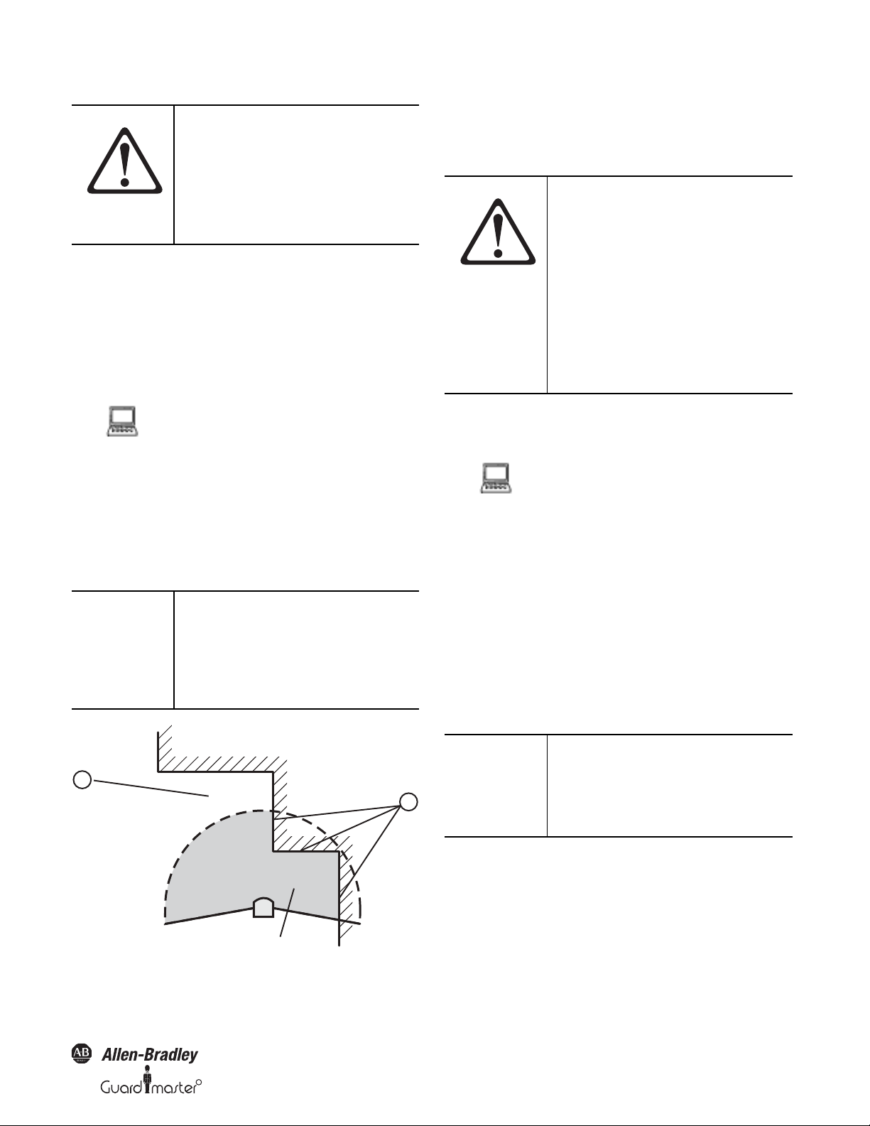
3.4.3 Using the contour of the protective safety field
as a reference
If the beams of the protective safety field reach as far as an obstacle (e.g. the
floor in vertical applications or the walls in horizontal applications), the
SafeZone multizone safety laser scanner can also monitor the contour of the
protective safety field.
12 10000073050, July 2011
Original instructions
You define the contour as a reference in the SCD
field set editor: Device symbol SafeZone safety laser
scanner, command Edit field sets… In the field set
editor window. Tools menu. Add contour command.
Vertical operation
In vertical operation (for access protection and hazardous point
protection) according to IEC/EN 61496-3 you must always configure and
activate the contour as reference function. If the radius of a protective safety
field exceeds 4 meters, then it must be ensured that changes to the
positioning of the safety laser scanner resulting in a movement of the
protective safety field of more than 100 mm are detected.
Recommendation Use vertical passage limits at the side (e.g.
door frames) and the floor as the reference. If
in this case the position of the SafeZone
safety laser scanner is changed in one or
more planes, the distance to the reference
changes and the SafeZone multizone safety
laser scanner switches its OSSDs to the OFF
state.
R
Page 15
R
Figure 16: Protective safety field as reference for vertical operation
Contours on the floor and the
side walls as reference
Door as reference
.
SafeZone™ Safety Laser Scanner User Manual
3.4.4 External device monitoring (EDM)
The EDM function monitors the contact elements activated by both the
OSSDs (e.g. contactors). The machine is only allowed to start if both
contactors are in the de-energized state on reset, that is they are
deactivated.
The SafeZone safety laser scanner monitors the contactors after every
interruption of the protective safety field and before the restart of the
machine. The EDM can in this way identify if one of the contactors has
welded in the following manner.
You can configure the external device monitoring in
the SCD (device symbol SafeZone safety laser
scanner system, context menu Configuration draft,
Edit..., file card Scanner name).
• If no internal restart interlock is configured, then
- the system locks completely (lock-out).
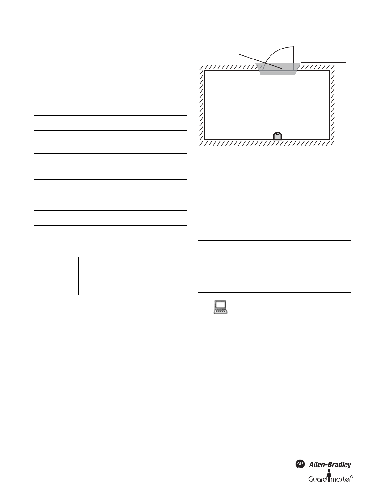
Horizontal operation
If the protective safety field reaches the walls of a room partially or
entirely, the SafeZone safety laser scanner can also monitor the contour
of the protective safety field. The OSSDs on the SafeZone multizone
safety laser scanner then change to the off status if the room contour
changes due the opening of a door, even if there is no object in the
protective safety field.
Figure 17: Protective safety field as reference for horizontal operation
IMPORTANT
AT TE N TI O N
It is not possible to define any warning
field in the areas of the contour
segments. This is only possible
between contour segments.
Each output signal switching device
(OSSD) is only allowed to be connected
to one switching element (e.g. relay or
contactor).
- the error message appears in the 7segment display.
• If an internal restart interlock is configured, then
- the SafeZone safety laser scanner
deactivates its OSSDs.
- the adjacent LED illuminates.
.
Notes
- the error message appears in the 7segment display.
- with the flashing LED the SafeZone safety
laser scanner signals that the control
switch for restarting or resetting the
restart must be operated.
• You will find examples on the connection of the
external device monitoring in Section 6.3
“Example circuits” on page 34.
• If you do not use the external device monitoring
function, leave the inputs disconnected (see
Section 5.1.1 “Pin assignments of the I/O
modules” on page 32).
3.4.5 Application diagnostic output
The application diagnostic output, when not configured, sources 24V
DC. When configured for contamination or status of outputs (OSSDs)
or both, the ADO will turn off to signal one of the configured states (see
Table 21 on page 40).
Original instructions
10000073050, July 2011 13
Page 16
SafeZone™ Safety Laser Scanner User Manual
The SafeZone safety laser scanner has a configurable
application diagnostic output (device symbol
SafeZone safety laser scanner system, context menu
Configuration draft, Edit..., file card Scanner name).
For the application diagnostic output you must
decide
• Whether it is deactivated.
• Whether an output signal is only active when the
front screen is contaminated.
• Whether an output signal is only active when an
error occurs.
• Whether an output signal is activated for both the
front screen contamination and on errors.
3.4.6 Restart
Figure 18: Schematic of operation with restart interlock
Restart interlock
The dangerous state of a machine or a vehicle is interrupted as soon as
there is an object in the protective safety field and is not enabled again ,
even if there is no longer an object in the protective safety field. The
OSSDs are only enabled again when the operator operates the control
switch for restarting or resetting.
The restart interlock can be implemented in two different ways:
• With the internal restart interlock of the SafeZone safety laser
scanner:
The outputs on the SafeZone safety laser scanner are enabled after the
connected control switch is operated.
• With the restart interlock of the machine controller:
The SafeZone safety laser scanner has no effect on the restart.
AT TE N TI O N
Place the control switch for restart or
reset outside the hazardous area in a
place where it can clearly be seen from
the hazardous area.
Place the control switch for restart or
reset outside the hazardous area such
that it cannot be operated by a person
in the hazardous area. Ensure that the
person who operates the control
switch has a full view of the hazardous
area.
Restart delay
On the SafeZone safety laser scanner, instead of a restart interlock you can
configure a restart delay of 2 to 60 seconds. This enables the machine or the
vehicle to start automatically when the protective safety field becomes
clear, and the pre-set time has elapsed. It is not possible to combine restart
interlock and restart delay.
AT T EN T IO N
It is important to configure the
SafeZone safety laser scanner with
restart interlock if a person cannot be
detected at every point in the hazard
area for the SafeZone safety laser
scanner.
Operators may be at risk if restart
interlock is not configured. Check, if
necessary, whether it is possible to
prevent personnel from approacing
the hazard point by design measures
(see Section 4.1.2 “Measures to protect
areas not covered by the SafeZone
safety laser scanner" on page 21).
IMPORTANT
The SafeZone safety laser scanner
cannot differentiate between a
contaminated front screen and an
obstacle directly in front of it. To ensure
high availability, the SafeZone multizone
safety laser scanner has been designed
such that it reliably detects dark black
bodies such as wide black cord or shoe
leather from a distance of 5 cm in front
of the front screen. Black objects that
are closer to the front screen may not be
detected.
AT T EN T IO N
Secure the area close to the SafeZone
safety laser scanner if operated without
restart interlock.
Make the area near the device
inaccessible by means of physical
measures (hard guard or recessing) or,
in addition to the SafeZone safety laser
scanner, use a proximity switch with 5
cm acquisition range. Without this
additional protection you will
endanger persons who move from the
protective safety field into the area
near the device.
14 10000073050, July 2011
Original instructions
R
Page 17
R
SafeZone™ Safety Laser Scanner User Manual
Permissible configuration
Table 4: Permissible configuration of the restart interlock
Restart Interlock of the
SafeZone
Deactivated Deactivated
Deactivated Activated
Activate d Deact ivated
Activate d Activa ted
Restart Interlock
Machine/Vehicle Permissible Application
Only if it is not possible to leave the
protective safety field to approach the
hazardo us point. Ensure that this is
All, if the hazardous area can be
completely seen by the
Only if it is not possible to leave the
protective safety field to approach the
hazardo us point. Ensure that this is
All, if the hazardous area cannot be
completely seen by the operator. The
restart interlock of the SafeZone safety
laser scanner takes over the function
for resetting the protective device.
Reset
IMPORTANT
The reset function is often also called
“preparation for restart.” In these
operating instructions the term reset is
typically used.
If you want to activate the restart interlock on the SafeZone safety laser
scanner (internal) and also a restart interlock on the machine (external),
then each restart interlock needs its own control switch.
If you do not use the restart interlock, leave the inputs disconnected (see
Section 5.1.1 “Pin assignments of the I/O modules” on page 32).
You can configure the type of restart in the SCD (device symbol SafeZone
safety laser scanner system, context menu Configuration draft, Edit..., file
card Scanner name).
3.4.7 Multiple sampling
When multiple sampling is set, an object must be scanned several times
before the SafeZone safety laser scanner switches off its OSSDs. In this
way you can reduce the probability that objects falling through the scan
plane, for example welding sparks or other particles, result in the
shutdown of the equipment.
With a multiple sampling configuration of (e.g., 3) an object must be
scanned three times in succession before the SafeZone safety laser
scanner switches off the OSSDs.
IMPORTANT
The total response time is increased by
the multiple sampling.
With a multiple sampling greater than
2, note that you must add a
supplement to the basic response time
(see Section 11.2 “OSSD response
times” on page 42)!
On the SafeZone safety laser scanner, a multiple sampling of 2 is the
minimum setting. You can set the multiple sampling up to 16 with the aid of
the SCD software.
After operating the control switch for the internal
restart interlock (with protective safety field
unoccupied)
• The SafeZone multizone safety laser scanner
switches on its OSSDs.
• The adjacent LED on the safety laser scanner
illuminates green.
The external restart interlock prevents the machine from restarting.
After resetting the SafeZone safety laser scanner the operator must press
the control switch to restart the machine controller.
AT TE N TI O N
Ensure that the correct sequence is
followed!
The controller must be configured such
that the machine only restarts if the
SafeZone safety laser scanner is first
reset and then the control switch for
restarting the machine controller is
pressed.
IMPORTANT
You will find examples on the
connection of the internal restart
interlock in Section 6.3 “Example
circuits” on page 34.
Table 5: Recommended multiple sampling
Recommended multiple sampling Application
2 times
4 times Mobile
8 times
Stationary under clean ambient
conditions
Stationary under dusty ambient
conditions
Recommendation Using multiple sampling you can increase
the availability of a machinery.
You can configure the multiple sampling in the SCD
software for each monitoring case (device symbol
SafeZone safety laser scanner system, context menu
Configuration draft, Edit..., Monitoring case name, file
card Scanner name).
3.4.8 Monitoring cases
If you are using the SafeZone multizone, you can define up to four
monitoring cases.
Original instructions
10000073050, July 2011 15
Page 18
SafeZone™ Safety Laser Scanner User Manual
IMPORTANT
Ensure that the safety distance to the
dangerous state is properly established
in any monitoring case to protect the
hazardous area.
See Section 4 “Installation and
mounting” on page 18.
It is possible to switch between these monitoring cases during operation
using static control inputs.
Park mode
For mobile applications in which vehicles are parked for a time, the
SafeZone multizone safety laser scanner can be switched to park mode.
In the park mode the OSSDs are deactivated and the laser beam in the
safety laser scanner will shutdown. In this way the power consumption of
the device is reduced.
The park mode can be configured for a monitoring case. To switch to the
park mode, the input must be configured such that the related
monitoring case with the park mode is activated.
Recommendation If you park vehicles beside each other,
switch them to the park mode. In this way
you prevent the SafeZone multizone safety
laser scanner on the vehicles from optically
interferring with each other and the
SafeZone multizone safety laser scanner
from possibly entering an error (lockout)
condition.
You can configure the monitoring cases in the SCD
software (device symbol SafeZone multizone safety
laser scanner system, context menu Configuration
draft, Edit...).
3.4.9 Static control inputs
The SafeZone multizone safety laser scanner has two two-channel static
control inputs through which the four possible monitoring cases can be
switched.
You can configure the control input in the SCD
software (device symbol SafeZone multizone safety
laser scanner system, context menu Configuration
draft, Edit..., file card Inputs).
IMPORTANT
When switching the monitoring cases
using static control inputs, please note
the following points:
Ensure that the control for the
monitoring case switching has a
sufficiently high level of safety.
Ensure that the circuit for the control
inputs is suitable for the ambient
conditions to be expected so that
systematic effects and thus errors on
the switching of the monitoring
cases can be excluded.
Ensure that the control—using static
control inputs—provides switching
between the monitoring cases in the
correct time frame. Note that at the time
of the switching there may be a person
in the protective safety field. Only by
means of switching in the correct time
frame (i.e. before the hazard occurs at
this point for the person) is protection
provided (see Section 4.5 “Timing for
monitoring case switching” on page 27).
Static complementary sampling
A control input comprises a pair of two connections. For correct
switching one connection must be inverted in relation to the other.
The following table shows the levels that must be present at the
connections for the control input to define the logical input state 1 and 0
at the related control input.
Table 6: Level at the connections for the control inputs for
complementary sampling
Connection 1 Connection 2 Logical Input State
100
011
11Error
00Error
Using the control input pair on the SafeZone multizone safety laser
scanner; four monitoring cases can be switched.
If you are using static sampling, decide between complementary or 1-of-n
sampling depending on the control features available.
16 10000073050, July 2011
Original instructions
Static 1-of-n sampling
With 1-of-n sampling you use each of the two control input connections.
All connections must be used, only one connection is ever allowed to be 1.
Table 7: Truth table for 1-of-n sampling
A1 A2 B1 B2
1000
0100
0010
0001
R
Page 19

R
Input delay
If the control device which is used to switch the static control inputs cannot
switch within 10 ms (for 60 ms basic response time) or 20 ms (for 120 ms
basic response time) to the related input condition (e.g. due to switch
bounce times), you must choose an input delay. For the input delay choose
the time in which your defined control device can switch to a
corresponding input condition.
Independent of the basic response time chosen for the SafeZone
multizone safety laser scanner, you can increase the input delay in 30-ms
steps (for 60 ms basic response time) or 60-ms steps (for 120 ms basic
response time).
The following figures, derived from experience, are a guide for the
various switching methods given.
Table 8: Figures from experience for the necessary input
delay
Switching method Input delay required
Electronic switching using controller or complementary electronic
outputs with 0 to 10 ms bounce time
Contact (relay) controls 30…150 ms
Control using independent sensors 130…480 ms
10 ms
SafeZone™ Safety Laser Scanner User Manual
You configure a monitoring case with simultaneous
field set in the SCD.
3.4.11 Naming applications and laser scanners
A name can be assigned to the application configured and to the laser
scanner(s). The names are saved in the devices after the configuration is
transferred. The name chosen may, for example, be the identifier for the
system or the machine.
If you assign unique application names, you may “reserve” the devices for
certain duties. A machine maintenance person comparing exchanged
devices with the configuration data saved in the SCD software will be
notified that the application name does not match. He may then
exchange these devices for those with the correct application name.
You can enter the application or scanner names in the
SCD software (device symbol SafeZone safety laser
scanner system, context menu Configuration draft,
Edit…, file card Application).
3.5 Indicators and outputs
3.4.10 Checking of the monitoring case switching
To check the switching between monitoring cases, configure a series of
monitoring cases. Here you can define either an arbitrary sequence, a
unique sequence, or two alternative sequences.
Arbitrary sequence: It is allowed to switch from one monitoring case to
any other defined monitoring case.
Unique sequence: It is only allowed to switch from a monitoring case to
another specifically defined monitoring case.
Alternative sequence: It is allowed to switch from a monitoring case to
one of two specifically defined monitoring cases.
Recommendation Use the checking of the monitoring cases as
an additional medium to exclude risks. For
example, deviations of a vehicle from a
corridor or a plant from the stipulated
production process can be detected.
Arbitrary sequence Unique sequence Alternative sequence
3.5.1 LEDs and 7-segment display
The LEDs and the 7-segment display indicate the operational status of
the SafeZone safety laser scanner. They are on the front face of the safety
laser scanner. Above the LEDs there are symbols that are used in the
remainder of these operating instructions to describe the LEDs.
Figure 20: Operational status indicators on the SafeZone safety laser
scanner
The symbols have the following meaning:
OSSDs deactivated (e.g. if object in the protective safety
field, reset necessary, lock-out)
Figure 19: Schematic layout of the monitoring case switching
Within a monitoring case, the SafeZone multizone can monitor two
field sets simultaneously (e.g. hazardous area on the left and hazardous
area on the right). For this purpose choose any further field set with the
related monitoring case as the simultaneous field set.
Original instructions
Reset required
10000073050, July 2011 17
Page 20

SafeZone™ Safety Laser Scanner User Manual
Warning field interrupted (object in warning field)
Front screen contaminated
OSSDs deactivated (e.g. if object in the protective safety
field, reset necessary, lock-out)
OSSDs activated (no object in protective safety field)
3.5.2 Outputs
Using the outputs on the SafeZone safety laser scanner you shutdown the
dangerous state on a machine, equipment or a vehicle and evaluate the
operational status of the SafeZone safety laser scanner. The SafeZone
safety laser scanner has the following outputs:
•OSSDs
•Warning field
• Application diagnostic output (contamination of the front screen/
error)
•Reset required
The outputs are brought out at the system connection (see Section 5.1
“System connection” on page 31).
IMPORTANT
All outputs are only allowed to be used
for the purpose specified. Note that the
signals at the application diagnostic
outputs for “warning field,”
“contamination of the front screen/
error” and “reset necessary” are not
safe. For this reason the warning field is
not allowed to be used for tasks related
to personnel protection.
AT T EN T IO N
No protective function without
sufficient safety distance.
The SafeZone safety laser scanner’s
safety function depends on the system
being mounted with the correct safety
distance from the hazardous area.
Section 4 — Installation and Mounting
This section describes the preparation and completion of the mounting of
the SafeZone safety laser scanner.
Mounting requires four steps:
• Definition of the application and the necessary mounting location for
the laser scanner
• Calculation of the protective safety field sizes
You can enter the calculated protective safety field sizes with the aid of
the SCD software. Or leave the SafeZone safety laser scanner to suggest
the protective safety fields. In the latter case it is necessary to check
whether the suggested sizes correspond to those calculated. Thus in any
circumstance you must calculate the protective safety field size.
• Definition of the switching point between monitoring cases
• Mounting the safety laser scanner with or without mounting kits
18 10000073050, July 2011
Original instructions
R
Page 21

R
SafeZone™ Safety Laser Scanner User Manual
IMPORTANT
• Mount the SafeZone safety laser
scanner in a dry place and protect
the device from dirt and damage.
• Avoid strong electrical fields.
These can be produced by
welding cables, induction cables in
the immediate vicinity and also by
mobile telephones operated in
close physical proximity.
• Ensure that there are no obstacles
in the area to be monitored in the
field of view of the SafeZone
safety laser scanner that could
cause interference or shadowing.
Such shadowed areas cannot be
monitored by the SafeZone safety
laser scanner. If there are
unavoidable shadowed areas,
check whether there is a risk. Take
additional safety precautions as
necessary.
• Keep the area to be monitored free
of smoke, fog, steam or other forms
of air impurities. Otherwise the
function of the SafeZone safety
laser scanner may be impaired
causing nuisance stops.
• Avoid placing highly reflective
objects in the scan plane of the
SafeZone safety laser scanner.
Examples: Retroreflectors can
affect the measurement results of
the SafeZone safety laser scanner.
Mirrored objects can hide part of
the area to be monitored.
• Mount the SafeZone safety laser
scanner such that it is not
saturated by incidental sunlight. Do
not position stroboscopic and
fluorescent lights directly in the
scan plane as these may affect the
SafeZone safety laser scanner in
specific circumstances.
• Mark the protective safety field on
the floor, if this is reasonable for
the application (see EN 61496,
part 1, Section 7).
The following steps are necessary after mounting and installation:
• Completing the elec trical connections (Se ction 5 “Electrical installation”
on page 31)
• Configuration of the protective safety field (Section 7
“Configuration” on page 35)
• Commissioning and checking of the installation (Section 8
“Commissioning” on page 36)
• Checking of the SafeZone safety laser scanner functionality and safe
shutdown of the machine, vehicle or equipment (Section 8.2 “Test
notes” on page 36)
4.1 Stationary application in horizontal
operation
This type of protective device is suitable for machines and equipment on
which a hazardous area is not enclosed by a fixed protective device.
Figure 21: Horizontally mounted stationary application
For a horizontally mounted stationary application determine
• The protective safety field size to observe the necessary safety
distance.
• The height of the scan plane.
•The restart behavior.
• Measures to protect areas not covered by the SafeZone safety laser
scanner.
IMPORTANT
4.1.1 Protective safety field size
The protective safety field must be so configured that a safety distance
(S) to the hazardous area is maintained. This safety distance ensures that
the hazardous point can only be reached after the dangerous state of the
machine has been completely stopped.
Once you have defined the protective
safety field size, mark the boundaries of
the protective safety field on the floor.
This avoids inadvertent entrance into
the protective safety field and makes it
possible to subsequently check the
shape of the protective safety field.
Original instructions
10000073050, July 2011 19
Page 22

SafeZone™ Safety Laser Scanner User Manual
IMPORTANT
If you are using the SafeZone
multizone, you can define several
monitoring cases with different
protective safety fields. In such cases
you must calculate the protective
safety field size for all protective safety
fields used.
You can operate the SafeZone safety laser scanner in stationary horizontal
operation with 50 mm or with 70 mm resolution. For each resolution you
can choose between 60 ms and 120 ms response time. The maximum
protective safety field range for the SafeZone safety laser scanner is given by
the resolution and the response time.
• If you choose a 50 mm resolution, the maximum protective safety field
range is less than for a 70 mm resolution, however you can mount the
SafeZone safety laser scanner as low as required.
• If you choose a 70 mm resolution, you can configure the largest
protective safety field range (5 m) but must position the scan plane of
the SafeZone multizone safety laser scanner at 300 mm.
AT TE N TI O N
Ensure that a human leg can be
detected in horizontal stationary
applications with 70 mm resolution.
Mount the scan planes for horizontal
stationary applications with 70 mm
resolution at a height of at least 300
mm (see “Height of the scan plane at
70 mm resolution” on page 26).
Recommendation Due to the choice of two resolutions and
two response times, it may be necessary to
repeatedly calculate the protective safety
field size (iterative calculation).
Perform your protective safety field calculation initially based on a
resolution of 50 mm and a basic response time of 60 ms.
If the calculated protective safety field is larger than the maximum
protective safety field range at 50 mm resolution, calculate it again using
the same resolution and the higher response time.
If the protective safety field calculated is larger than the maximum
protective safety field range achievable, then re-calculate the protective
safety field with the lower resolution.
The safety distance S depends on:
• Approach speed of the body or parts of the body
• Stopping/run-down time of the machine or system
(The stopping/run-down time is shown in the machine
documentation or must be determined by taking a measurement.)
• Response time of the SafeZone safety laser scanner
• Supplements for general measurement errors and any measurement
errors related to reflection
• Supplement for prevention of reaching over
• Height of the scan plane
• Possibly the time for switching between the monitoring cases
Calculation of the safety distance S:
First, calculate S using the following formula:
S = (K x (TM + TS )) + ZG + ZR + C
Where...
K = Approach speed (1600 mm/s, defined in EN 999)
T
M = Stopping/run-down time of the machine or system
T
S = Response time of the SafeZone multizone safety laser scanner
combined with the downstream controller
Z
G = General safety supplement = 100 mm
ZR = Supplement for measurement error related to reflection
C = Supplement for prevention of reaching over
Response time TS of the SafeZone safety laser scanner
The response time T
S of the SafeZone safety laser scanner depends
on
•The resolution used
• The multiple sampling used
See Section 11.2 “OSSD response times” on page 42.
Supplement ZR for measurement error related to
reflection
AT T EN T IO N
Avoid mounting retroreflectors at a
distance of less than one meter from
the boundary of the protective safety
field.
With retroreflectors positioned at a
distance of less than 1 m from the
boundary of the protective safety field
a supplement, ZR, of 200 mm must be
added to the protective safety field.
Supplement C for protection against reaching over
With a protective safety field installed horizontally, there is a risk that
people may reach over the prote ctive safety field and in this way reach the
hazardous area before the SafeZone safety laser scanner shuts down the
hazardous motion. For this reason the calculation of the safety distance
must take into account a supplement to prevent persons from finding
themselves in a hazardous situation by reaching over the protective safety
field (see EN 294, table 1) before the SafeZone safety laser scanner
detects the intrusion to the protective safety field.
20 10000073050, July 2011
Original instructions
R
Page 23

R
Figure 22: Risk of reaching over (mm)
058 = C0021 = C
HD = 0
HD = 875
XX
Y
Y
The necessary supplement for the safety distance is dependent on the
height of the scan plane for the protective safety field. At low heights
the supplement is larger than at greater heights .
AT TE N TI O N
Prevent the possibility of crawling
beneath the protective device if you
mount it higher than 300 mm.
Prevent people from being able to crawl
beneath the protective safety field by
means of appropriate mounting of the
SafeZone safety laser scanner. If you
mount the protective device higher
than 300 mm, then prevent crawling
beneath by means of additional
measures. For applications that are
accessible to the public, the mounting
height may need to be reduced to 200
mm (see the appropriate public
regulations).
How to calculate the supplement C:
If there is enough empty space in front of your machine or equipment,
use 1200 mm for the supplement C.
If the safety distance is to be kept as small as possible, calculate C
using the following formula :
C = 1200 mm - (0.4 x H
Here HD is the height at which the protective safety field is mounted.
IMPORTANT
D )
The minimum supplement to prevent
reaching over is 850 mm (arm length).
SafeZone™ Safety Laser Scanner User Manual
Table 9: Advantages and disadvantages of mounting methods
Mounting Orientation Benefit Disadvantage
Scanner low (H
Inclination of the scanner plane
Scanner high (H
Inclination of the scanner plane
Scanner low (H
Inclination of the scanner plane
H
D = Detection height
H
S = Scanner mounting height
S < 300 mm)
S > 300 mm)
S < 300 mm)
No external effects d ue to
saturation, crawling
Lower protective safety field
supplement C
Lower protective safety field
supplement C
Larger supplement C
Danger of crawling beneath
(at the front and side)
Danger of crawling beneath (at
the front),
Height of the scan plane at 70 mm resolution
Due to the radial sampling of the protective safety field, the optical
resolution will be lower the further away you get from the scanner.
Figure 24: Relationship between resolution and protective safety field
mounting height
If you choose a resolution of 70 mm in the SCD software for hazardous
area protection, a human leg may, in certain circumstances, not be
detected. The reason in this case would be that the beams miss the ankle
on the left and right .
If you mount the SafeZone safety laser scanner higher, the scan plane is at
fibula height and the leg is also detected with an object resolution of 70 mm
.
4.1.2 Measures to protect areas not covered by the
SafeZone safety laser scanner
During mounting, areas may be found that are not covered by the safety
laser scanner.
In summary there are three practical methods of mounting the scan plane
for the SafeZone safety laser scanner. The optimal method depends on
the related application.
H
S
H
D
H
S
C
H
D
Figure 23: Mounting methods for the scan plane
H
S
CC
H
D
These areas become larger if the SafeZone safety laser scanner is
mounted using the mounting kits.
Table 9 provides assistance in making the selection.
Original instructions
Figure 25: Unprotected areas for stationary applications
10000073050, July 2011 21
Page 24

SafeZone™ Safety Laser Scanner User Manual
Contours on the floor and the
side walls as reference
Table 10: Size of the unprotected areas
Size of Unprotected Areas
Mounting Method X Y
Direct mounting
With mounting kit 1
With mounting kit 1 and 2
With mounting kit 1, 2 and 3 142 mm 805 mm
AT TE N TI O N
Prevent unprotected areas.
109 mm 618 mm
112 mm 635 mm
127 mm 720 mm
Mount the SafeZone safety laser
scanner such that there are no
unprotected areas. Take one of the
precautions given in the following:
Install hard guards to prevent
standing behind.
Install the SafeZone safety laser
scanner in a recess.
Mounting with hard guards
scanner (Figure 26) and such that standing in an unscanned area
is not possible.
IMPORTANT
Prevent crawling beneath the recess by
limiting the height of the recess such
that nobody can crawl beneath.
4.2 Stationary Vertical Operation for Access
Protection
Access protection can be used when the access to the machine can be
defined by physical means. For access protection the SafeZone safety
laser scanner detects the entry of an entire body.
IMPORTANT
To ensure adequate access protection,
a response time of ~ 90 ms and a
resolution of 150 mm or finer is
required.
To protect the SafeZone multizone
scanner against inadvertent
adjustment or manipulation, use the
contour of the surrounding area as a
reference (see Section 3.4.3 “Using the
contour of the protective safety field as
a reference” on page 12).
Figure 26: Example of mounting with hard guards
Fit the hard guard such that the areas not covered by the safety laser
scanner are completely protected against personnel standing in them.
Mounting in a recess
Figure 27: Form of the recess
Design the recess to be sufficiently deep enough that it
completely covers the area not protected by the safety laser
4.2.1 Safety distance
For access protection, a safety distance (S) must be maintained between
protective safety field and hazardous area. This safety distance ensures
that the hazardous point can only be reached after the dangerous state of
the machine has been completely stopped.
Figure 28: Access protection
22 10000073050, July 2011
Original instructions
R
Page 25

R
SafeZone™ Safety Laser Scanner User Manual
The safety distance S as defined in EN 999 and EN 294
depends on:
• Reach or approach speed
• Stopping/run-down time of the machine or system
(The stopping/run-down time is shown in the machine
documentation or must be determined by taking a measurement.
On request Rockwell safety services can perform a detailed stopping/
run-down measurement on your equipment.)
• Response time of the SafeZone safety laser scanner
• Supplement C against reaching through
Calculation of the safety distance S:
First, calculate S using the following formula:
S = (K x (TM + TS )) + C
Where...
= Approach speed (1600 mm/s, defined in EN 999)
K
= Stopping/run-down time of the machine or system
T
M
= Response time of the SafeZone multizone safety laser scanner
T
S
= Supplement against reaching through (850 mm)
C
Response time TS of the SafeZone safety laser scanner
AT TE N TI O N
The overall response time of the
SafeZone safety laser scanner must not
be more than 90 ms for access
protection.
If a critical response time is exceeded (for
an object diameter of 150 mm and a
speed of 1.6 m/s that is 90 ms) a person
may no longer be detected under
certain circumstances. The critical
response time is exceeded if the basic
response time is too high, possibly due
to multiple sampling or due to the
usage of external OSSDs.
In specific cases agreed with the
responsible authorities higher response
times may be allowed (for example by
increasing the detection time available
by positioning the scanner at an angle).
In this case ensure that the areas the
scanner cannot see are protected by
additional measures.
The response time TS of the SafeZone safety laser scanner depends on
• The multiple sampling used.
• The transmission speed to external OSSDs over communication lines.
See Section 11.2 “OSSD response times” on page 42.
4.3 Stationary vertical operation for
hazardous point protection
Hazardous point protection is necessary if the operator must remain near
the dangerous state of the machine. Hand protection must be released for
hazardous point protection.
IMPORTANT
AT T EN T IO N
• To protect the protective device against inadvertent adjustment or
manipulation, use the contour of the surroundings as a reference for
the SafeZone safety laser scanner (see Section 3.4.3 “Using the
contour of the protective safety field as a reference” on page 12).
4.3.1 Safety distance
For hazardous point protection, a safety distance must be observed
between protective safety field and hazardous point. This safety distance
ensures that the hazardous point can only be reached after the dangerous
state of the machine has been completely stopped.
You can operate the SafeZone multizone safety laser scanner with 30 mm
or 40 mm resolution for hazardous point protection. At each resolution
you can choose a response time between 60 ms and 120 ms (due to the
proximit y of the hazardous point in the majority of cases only the shorter
response time can be used). The maximum protective safety field range
and the minimum distance to the hazardous point is given by the
resolution and the response time.
• If you choose 30 mm resolution, the protective safety field that can be
configured is smaller (for smaller hazardous points to be protected),
however you can mount the SafeZone multizone safety laser scanner
nearer to the hazardous point.
• If you choose 40 mm resolution, the protective safety field that can be
configured is larger (thus for larger hazardous points to be protected),
however you must mount the SafeZone multizone safety laser scanner
further away from the hazardous point.
AT T EN T IO N
To provide hand protection with
hazardous point protection a
resolution of at least 40 mm is require d.
The SafeZone multizone safety laser
scanner provides a maximum
resolution of 30 mm.
Never use the SafeZone safety laser
scanner for applications in which finger
protection is required
Due to the maximum resolution of 30
mm, the SafeZone safety laser scanner
is not suitable for finger protection.
Danger due reaching around or
reaching behind.
Always mount the scanner such that
reaching around and behind is
impossible. Provide suitable additional
precautions as necessary.
Original instructions
10000073050, July 2011 23
Page 26

SafeZone™ Safety Laser Scanner User Manual
Contour of the floor and
side walls as reference
Figure 29: Safety distance to the hazardous area
The safety distance as defined in EN 999 and EN 294 depends
on:
• Stopping/run-down time of the machine or system
(The stopping/run-down time is shown in the machine
documentation or must be determined by taking a measurement.)
• Response time of the SafeZone safety laser scanner
• Reach or approach speed
• Resolution of the SafeZone safety laser scanner
Calculation of the safety distance S:
First, calculate S using the following formula:
S = 2000 x (T
Where...
IMPORTANT
M + TS) + 8 x (d - 14 mm) [mm]
= Safety distance (mm)
= Stopping/run-down time of the machine or system
= Response time of the SafeZone safety laser scanner
= Resolutions of the SafeZone safety laser scanner (mm)
The reach/approach speed is already
included in the formula.
If the result S is ≤ 500 mm, then use the determined value as the safety
distance.
If the result S > 500 mm, you may be able to reduce the safety
distance using the following calculation:
S = 1600 x (T
If the new value S is > 500 mm, then use the newly calculated value as
the minimum safety distance.
M + TS) + 8 x (d - 14 mm) [mm]
If the new value S is ≤ 500 mm, then use 500 mm as the minimum safety
distance.
Response time of the SafeZone safety laser scanner
The response time TS of the SafeZone safety laser scanner depends
on
•The resolution used
• The multiple sampling used
See Section 11.2 “OSSD response times” on page 42.
4.4 Mobile applications
If the dangerous state is produced by a vehicle (e.g. AGV or fork lift), the
hazardous area that is produced by the movement of the vehicle is
protected by the SafeZone safety laser scanner.
IMPORTANT
For a horizontally mounted mobile application, determine:
• Protective safety field length
• Protective safety field width
• Height of the scan plane
• Restart configuration
• Methods of preventing unprotected areas
4.4.1 Protective safety field length
You must configure the protective safety field such that a safety distance to
the vehicle is maintained. This ensures that a vehicle monitored by the
SafeZone safety laser scanner comes to a stop before a person or object is
reached.
The SafeZone safety laser scanner may
only be used to protect vehicles
powered by electric motor.
Due to the movement of the SafeZone
safety laser scanner in a mobile
application, a resolution of 70 mm is
sufficient for the detection of people.
In the following calculations only take
into account the velocity of the vehicle,
not the speed of the person walking.
This is based on an understanding that
the person will recognize the danger
and stand still.
If the application is to protect vehicles
from collisions, then it will be necessary
to establish guidelines. These are
application specific and can therefore
not be described within this manual.
Contact the relevant authorities and
clarify the guidelines that must be
taken into account with regard to your
application.
24 10000073050, July 2011
Original instructions
R
Page 27

R
You can define different monitoring cases with different protective safety
S
AnF
S
Br
S
A
S
AnS
SafeZone
Necessary
safety field
depth
Braking distance of the vehicle
Safety supplement
Velocit
Stopping distance
Necessary
safety field
depth
Braking distance of the vehicle
Safety supplement
Velocit
Stopping distance
fields. You can switch these using the static control input.
Calculation of the protective safety field length:
Calculate the necessary protective safety field length using the formula:
+ ZG + ZR + ZF + Z
SL = S
A
B
Where...
= Stopping distance (mm)
A
= General safety supplement = 100 mm
Z
G
Supplement for any measurement error of the SafeZone multizone safety
=
Z
R
Z
F
Z
B
laser scanner related to reflection
= Supplement for any lack of ground clearance of the vehicle
Supplement for the reduction in the braking performa nce of the vehicle
as defined in the related vehicle documentation
Stopping distance
The stopping distance comprises the braking distance for the vehicle, the
distance covered during the response time of the safety laser scanner and
the response time of the vehicle controller.
SafeZone™ Safety Laser Scanner User Manual
y
y
Figure 31: Braking distance as a function of the vehicle velocity
Figure 30: Stopping distance
IMPORTANT
Take into account that the braking
distance for a vehicle is not linear with
increasing velocity, but increases in a
square function.
Calculation of the stopping distance:
Calculate the stopping distance using the formula:
SA = S
Br
+ S
AnF
+ SAnS
Where...
= Braking distance from the vehicle documentation
S
Br
Distance covered during the response time of the vehicle controller from
=
S
AnF
S
AnS
the vehicle documentation
= Distance covered during the response time of the safety laser scanner
Distance covered during the response time of the safety laser
scanner
The distance covered during the response time of the safety laser scanner
depends on
• The response time of the safety laser scanner.
• The maximum velocity of the vehicle in your mobile application.
The response time TS of the SafeZone multizone safety laser
scanner depends on
• The multiple sampling used.
See Section 11.2 “OSSD response times” on page 42.
Calculation of the distance covered during the response time of the safety
laser scanner:
Calculate the distance using the formula:
S
= T
x V
AnS
S
max
Where...
Original instructions
10000073050, July 2011 25
Page 28

SafeZone™ Safety Laser Scanner User Manual
Ground clearance
Safety field length Z
F
SafeZone
= Response time of the safety laser scanner
= Maximum velocity of the vehicle from the related vehicle documentation
V
max
Supplement ZR for measurement error related to
reflection
With retroreflectors in the background at a distance of less than 1
m from the boundary of the protective safety field, the supplement
Z
is 200 mm.
R
Supplement due to lack of ground clearance
This supplement is necessary because a person is generally detected above
the foot and the braking action can therefore not take into account the
length of the foot in front of the detection point. If a vehicle has no ground
clearance, a person need additional protection at foot level.
Figure 32: Supplement due to lack of ground clearance
The supplement for foot space below 120 mm is 150 mm. If you
wish to further reduce this supplement, read the supplement
necessary from the following diagram:
Calculation of the protective safety field width:
Calculate the protective safety field width SB using the formula:
SB = FB + 2 x (ZG + ZR + ZF)
Where...
=Vehicle width
F
B
= General safety supplement = 100 mm
Z
G
Supplement for any measurement error of the SafeZone multizone safety
=
Z
R
Z
F
laser scanner related to reflection
= Supplement for any lack of ground clearance of the vehicle
Figure 34: Protective safety field width
Note: Normally, an installer will mount the SafeZone safety laser scanner
in the middle of the vehicle . If this is not the case, then you must
define the protective safety field asymmetrically . (The SCD represents
the fields as they appear in the monitoring on the scanner.) Ensure that
there are supplements on the right and left of the vehicle .
120
the vehicle
Ground clearance of
60
50
050100150
Supplement Z in mm
Figure 33: Diagram of ground clearance of the vehicle
4.4.2 Protective safety field width
The width of the protective safety field must take into account the width
of the vehicle, the supplements for the measurement error and the lack of
ground clearance.
4.4.3 Height of the scan plane
AT T EN T IO N
Mount the SafeZone safety laser
scanner such that the scan plane is at a
maximum height of 200 mm.
Any item lying flat on the floor will be
reliably detected. Tilting the protective
safety field, which will result in objects
with a diameter of 200 mm not being
detected, is not allowed. We
recommend aligning the scan plane at
150 mm.
Safety field
length set
Max. 272 mm
Figure 35: Mounting height
150 mm
26 10000073050, July 2011
Original instructions
R
Page 29

R
4.4.4 Methods of preventing unprotected areas
When the SafeZone safety laser scanner is mounted on a plane surface,
there are areas in front of the mounting surface that are not covered by
the safety laser scanner.
Figure 36: Unprotected areas for mobile applications
These unprotected areas become larger if you mount the SafeZone
safety laser scanner using mounting kits.
Table 11: Unprotected areas
Mounting Method Size of the Unprotected Areas
Direct mounting 109 mm
With mounting kit 1 112 mm
With mounting kit 1 and 2 127 mm
With mounting kit 1, 2 and 3 142 mm
AT TE N TI O N
Secure the unprotected areas.
If a vehicle is accelerated to a maximum
velocity of 0.3 m/s in less than three
seconds when in operation, you must
prevent personnel from entering the
unprotected areas by means of
mechanical trim panels, switch strips or
fitting the SafeZone safety laser scanner
in the vehicle trim panels.
Fitting in the vehicle trim
Build the SafeZone safety laser scanner into the vehicle trim such that the
unprotected areas are ≤ 70 mm and the SafeZone safety laser scanner
projects a maximum of 109 mm beyond the front of the vehicle. The
vehicle may then be accelerated to a velocity of 0.3 m/s within a second.
SafeZone™ Safety Laser Scanner User Manual
Figure 37: Fitting the SafeZone safety laser scanner in the vehicle trim
Additionally, protect the area near to the scanner (5 cm wide area in front
of the front screen) using a proximity switch with 5 cm acquisition range.
Otherwise make the area near the scanner impassable with a bar or a
recess. The vehicle may then be accelerated as required.
IMPORTANT
Note that the system must be fitted e.g.
in a trim panel without impairing the
optical beam path. The attachment of
an additional front screen is thus not
permitted. Any slot for the field of view
must be adequately sized (see Fig. 69 in
Section 11.5 “Dimensional drawings” on
page 50).
Recommendation If, when observing all necessary safety
precautions, you are able to avoid the use of
a restart interlock, you will increase the
availability of your vehicle.
4.5 Timing for monitoring case switching
If you switch between several monitoring cases, along with the safety
distance to the dangerous state there is a further safety-relevant aspect that
you must address.
If you can switch within 10 or 20 ms, the chosen protective safety field is
available within the response time of the SafeZone safety laser scanner. For
this reason you can initiate the switching at the time at which you actually
want to switch from one monitoring case to the other.
However, you must advance the timing of the switching if you
• Have entered an input delay for your switching method (see “Input
delay” on page 17).
• Control external OSSDs instead of the internal OSSDs The
following diagram shows the relationships:
Original instructions
10000073050, July 2011 27
Page 30

SafeZone™ Safety Laser Scanner User Manual
tttt
UFVz4
t
FU2zVFU3zVFU
t
UvtU
t
Figure 38: Advancement for the switch timing
• If the input conditions are present at the control inputs within 10 or 20
ms (cf. ), the timing for the switching (tUF) does not need to be
advanced.
• If an input delay for the control inputs needs to be taken into account
(cf. ), the timing for the switching
must be advanced by the
(tUFVz2)
input delay.
• If external OSSDs are used, the timing for the switching
(tUFVz4)
must
be further advanced by 20 ms (cf. ().
AT TE N TI O N
Define the timing for the switching
such that the SafeZone safety laser
scanner already detects a person in the
protective safety field before the
dangerous state occurs.
At the time of the switching there may
be personnel in the protective safety
field. Only by means of switching in the
correct time frame (i.e. before the
hazard occurs at this point for the
person) is protection provided.
Figure 39: Example of advancing the timing for the switching
The gantry robot moves to the right . On the left hand side the
dangerous movement is monitored by a monitoring case . When the
gantry robot arrives at the point
switching must have already been
tUv,
performed due to the advancing of the switching necessary so that at time
the right monitoring case is active.
t
U
Note: For the movement to the left, that is for the switching to the
monitoring case , the same applies.
How far you must advance the timing for the switching
depends on
• The input delay your switching method requires to provide the input
condition for case switching (see “Input delay” on pag e 17).
IMPORTANT
In the phases before and after the
switching, the safety distances
calculated for the individual
monitoring cases apply on their own.
The considerations above serve only
for the selection of the optimal timing
of the switching.
If the timing for the switching cannot be
exactly defined, e.g. due to the variable
processing speed of the machine, or if
advancing of the timing results in
premature termination of the
monitoring of the initial area, you must
→
→ Have both hazardous areas
monitored temporarily using
The following figure shows an example for a gantry robot that is
protected using two monitoring cases.
simultaneous monitoring.
28 10000073050, July 2011
Original instructions
R
Page 31

R
SafeZone™ Safety Laser Scanner User Manual
M6 x
8
4.6 Mounting steps
IMPORTANT
Special features to note during
mounting:
Mount the SafeZone safety laser
scanner such that it is protected from
moisture, dirt and damage.
Ensure that the front screen field of
view is not restricted.
Mount the scanner such that the
indicators are easy to see.
Always mount the SafeZone safety laser
scanner such that you can plug in and
remove the system connection.
Avoid excessive shock and vibration
loading on the safety laser scanner.
On applications that suffer from heavy
vibration, prevent the mounting
screws from coming loose using screw
locking devices.
Regularly check the tightness of the
mounting screws.
Prevent personnel from being able to
crawl beneath, stand behind or climb
over the protective safety field by
means of appropriate mounting of the
SafeZone safety laser scanner.
• Mounting with mounting kit 1, 2, and 3
The mounting kits build one on another. For mounting with kit 2 you will
therefore also need kit 1. For fixing with mounting kit 3 you will therefore
also need mounting kits 1 and 2. You will find the part numbers for the
mounting kits in Section 12.2 “Accessories and replacement parts” on page
53.
IMPORTANT
Observe the maximum torque of the
fastening hardware for the SafeZone
M6 on rear = 12 km max
M8 on side = 16 km max
Direct mounting
The SafeZone safety laser scanner has four threaded holes M6 x 8 on its
rear face. Using these holes you can directly mount the SafeZone safety
laser scanner by drilling through the mounting surface from the rear.
Figure 41: Threaded holes for direct mounting
Figure 40: Prevent crawling beneath, standing behind, climbing over
The origin of the scan plane is 63 mm above the bottom edge of the
SafeZone safety laser scanner. If you mount the SafeZone safety laser
scanner using mounting kit 3, then the origin of the scan plane is 102 mm
above the bottom edge of mounting kit 3 (see Section 11.5.3 “Scan plane
origin” on page 51).
There are four possible ways of mounting the SafeZone safety laser
scanner:
• Direct mounting without mounting kit
• Mounting with mounting kit 1
• Mounting with mounting kit 1 and 2
Recommendation Use mounting kit 1. This will make the
device easier to remove.
4.6.2 Mounting with mounting kit 1
With the aid of mounting kit 1 you can mount the SafeZone safety laser
scanner indirectly on the mounting surface. This is always necessary if
you cannot drill through the mounting surface from the rear.
Mounting kit 1
Mounting screws
for the sensor
Threaded mounting holes
M8 x 9
Figure 42: Mounting with mounting kit 1
Original instructions
10000073050, July 2011 29
Page 32

SafeZone™ Safety Laser Scanner User Manual
Threaded mounting holes
M8 x 9
Mounting screws
for the sensor
Mounting kit 1
Mounting kit 2
Threaded Mounting holes
M8 x 9
Mounting kit 1
Mounting screw
for the sensor
Mounting kit 2
Mounting kit 3
100 mm
200 mm
200 mm
Mount kit 1 on the mounting surface.
Mount the SafeZone safety laser scanner on mounting kit 1.
4.6.3 Mounting with mounting kit 2
With the aid of mounting kit 2 (only in conjunction with mounting kit 1)
you can align the SafeZone safety laser scanner in two planes. The
maximum adjustment angle is ±11° in both planes.
Figure 43: Mounting with mounting kit 2
Mount kit 2 on the mounting surface.
Mount kit 1 on mounting kit 2.
Mount the SafeZone safety laser scanner on kit 1.
Adjust the SafeZone safety laser scanner longitudinally and cross-wise.
Finally mount the SafeZone safety laser scanner on mounting kit 1.
Adjust the SafeZone safety laser scanner longitudinally and cross-wise.
IMPORTANT
During mounting, please observe the
dimensional drawings in “Technical
specifications” (see Section 11.5
“Dimensional drawings” on page 50).
4.6.5 Adhesive label Important information
On completion of mounting, you must affix the self-adhesive label
Important information supplied with the SafeZone safety laser scanner:
- Use only the information label in the language which the
operators of the machine understand.
- Affix the label such that it is clearly visible for the users/
operators during operation. The label must not be
covered even after additional items have been mounted.
4.6.6 Using multiple SafeZone safety laser scanners
The SafeZone safety laser scanner is so designed that mutual interference
between several scanners is unlikely. To completely exclude erroneous
switching, you must mount the scanners as shown in the following
examples.
IMPORTANT
Use the mounting kits 1 to 3 to adjust the scanners to different angles
(see Section 12.2 “Accessories and replacement parts” on page 53).
In all circumstances observe EN 999.
4.6.4 Mounting with mounting kit 3
With the aid of mounting kit 3 (only in conjunction with mounting kits
1 and 2) you can mount the SafeZone multizone safety laser scanner such
that the scan plane is parallel to the mounting surface. This enables stable
floor mounting or ensures that mounting kit 2 remains precisely
adjustable cross-wise on uneven wall surfaces.
Figure 44: Mounting with mounting kit 3
Mount kit 3 on the mounting surface.
Mount kit 2 on kit 3.
Mount kit 1 on kit 2.
30 10000073050, July 2011
Original instructions
Figure 45: Opposite mounting
Figure 46: Inclined, parallel mounting
Figure 47: Offset parallel mounting
R
Page 33

R
Figure 48: Mounting on a cross
200 mm
Figure 49: Reverse mounting, parallel
SafeZone™ Safety Laser Scanner User Manual
5.1 System connection
All input and output connections for the SafeZone safety laser scanner are
located on the system connector. This comprises of a
30-pin screw terminal connector and is located in the system connector.
100 mm
Section 5 — Electrical Installation
AT TE N TI O N
IMPORTANT
Switch the entire machine/system off
line.
The machine/system could
inadvertently start up while you are
connecting the devices.
Ensure that the entire machine/system
is disconnected during the electrical
installation.
Route all cables and connection cables
such that they are protected from
damage.
If you use the SafeZone safety laser
scanner for the protection of
hazardous areas: Ensure that any
control systems or other devices
forming part of the safety installation
meet the stipulated control category.
Ensure that the SafeZone safety laser
scanner is adequately protected
electrically. You will find the electrical
data necessary for determining the
correct fuse in Section 11.4 “Data sheet”
on page 45.
Figure 50: Screw terminal strip on the system plug
AT TE N T IO N
If the cable fitting is missing or not
tightened, or if mounting screws are
missing or not tightened on the system
connector, the IP65 enclosure rating is
not met.
All inputs and outputs for the SafeZone
safety laser scanner are to be used only
in the context specified.
The electrical connections for the SafeZone safet y laser scanner are made at
the system connector. It contains connections for the inputs, outputs and
the supply voltage. You can either make connections directly to the
terminal strip on the system connector or use a pre-assembled system
connector from Rockwell (see Section 5.3 “Pre-assembled system plugs” on
page 33).
Original instructions
10000073050, July 2011 31
Page 34

SafeZone™ Safety Laser Scanner User Manual
5.1.1 Pin assignments of the I/O modules
Pin Signal Function
1
+24V DC Supply voltage SafeZone Multizone
2
0V DC Supply voltage SafeZone Multizone
3
OSSD1 Output signal switching device
4
OSSD2 Output signal switching device
5
RESET Input, reset
6
EDM Input, external device monitoring
7
ERR Application diagnostic output~error/
8
RES_RE Q Out put, reset requ ired
9
WF Output, object in warning field
10
A1 Static control input A
11
A2 Static control input A
12
B1 Static control input B
13
B2 Static control input B
14
15
16
+24V DC
17
GND
18
19
20
+24V DC
21
GND
22
23
24
25
RxD
26
RxD+
27
TxD +
28
TxD
29
30
Reserved—Do not use
Reserved—Do not use
Supply voltage output
Reserved—Do not use
Reserved—Do not use
Supply voltage output
Reserved—Do not use
Reserved—Do not use
RS-422 interface for output of measured
data
Reserved—Do not use
Reserved—Do not use
SafeZone
Singlezone
SafeZone
Multizone
XX
XX
XX
XX
XX
XX
XX
XX
XX
X
X
X
X
5.2 System connector assembly
The system plug has holes on the top and rear. Suitable cable glands for
these holes are included with the device.
AT T EN T IO N
The length of the spare cable should be such
that the system plug cannot inadvertently be
plugged into a neighboring SafeZone safety
laser scanner.
From experience 20 to 30 cm spare cable at the
scanner have proven to adequate. In this way
you avoid the inadvertent connection of the
system connector to an adjacent SafeZone
safety laser scanner and operation of a SafeZone
safety laser scanner with an incorrect
configuration. The spare cable enables you to
easily change out the SafeZone safety laser
scanner.
Cable glands on the top
Cable glands on the
rear
Figure 51: System connector for SafeZone safety laser scanner
Depending on the application use suitable cable glands on the top or rear.
Cable Gland
M20 6…12 (0.24…0.47)
M12 (only if supplied) 3…6.5 (0.12…0.26)
Cable Diameter [mm
Usage
• System cables (supply
voltage, outputs, static
• Control switch for
restart or reset
• RS-422 data cables
Use the following cable cross-sections for the individual connections:
• One cable gland with M20 cable fitting
• Two blanking plugs for the unused outlets
Note: You can also purchase the SafeZone multizone safety laser scanner
with pre-assembled system connectors (see Section 5.3 “Pre-assembled
system connector” on page 33 and Section 12 “Ordering information” on
page 52).
32 10000073050, July 2011
Original instructions
Cable Recommended Cable Shielded
System cables (sup ply voltage,
outputs, static input)
Control switch for restart or reset
RS-422 data cables
9…13 conductors,
2
0.5…1 mm
2
2 x 0.25 mm
2
4 x 0.25 mm
No
No
Yes
R
Page 35

R
Recommendation If you do not want to assemble the system
SafeZone singlezone with one
protective safety field and warning
field — mounted horizontally
SafeZone with one protective
safety field — mounted vertically
Floor and posts a
reference
connector yourself, you will find suitable
cables in the
ordering information (see Section 12
“Ordering information” on page 52).
5.3 Pre-assembled system connectors
The following pre-assembled system connector with cable outlet on the
top are available for the connection of the SafeZone multizone safety
laser scanner (see also Section 12 “Ordering information” on page 52):
SafeZone™ Safety Laser Scanner User Manual
6.1 Stationary Applications
6.1.1 Applications with one monitored area (SafeZone
safety laser scanner)
Pin Signal Wire Color
1+24V DC Brown X X
20V DC Blue X X
3 OSSD1 Grey X X
4 OSSD2 Pink X X
5 RESET Red X X
6EDM Yellow X X
7ERRWhite/blackX X
8 RES_REQ Red/blue X X
9WFWhite/brownX X
10 A1 White/red X
11 A2 White/orange X
12 B1 White/yellow X
13 B2 White/green X
Top mounted cable entries (cable gla nds to the rear sealed with blanking plugs) are available.
SafeZone
Singlezone
SafeZone
Multizone
Section 6 — Application and Circuit
Examples
The examples shown are only provided as an aid for your planning. You
may need to consider additional protection measures for your
application.
In the examples with protective safety field switching, note that at the
time of the switching there may already be a person in the protective
safety field. Only by means of switching in the correct time frame (i.e.
bef ore the danger occurs at th is point) is reliable prote ction provided (see
Section 4.5 “Timing for monitoring case switching” on page 27).
Figure 52: Hazardous area protection with SafeZone singlezone
safety laser scanner
The area is permanently monitored by the SafeZone singlezone safety
laser scanner.
Figure 53: Access protection with SafeZone safety laser scanner
The access is monitored permanently. For safety against manipulation of
the SafeZone safety laser scanner the floor is used as a reference. If the
position of the SafeZone safety laser scanner changes (e.g. due to change
to the mounting), the SafeZone safety laser scanner shuts down.
Original instructions
10000073050, July 2011 33
Page 36

SafeZone™ Safety Laser Scanner User Manual
SafeZone multizone with two
protective safety fields and
warning fields — mounted
horizontally
SafeZone multizone with
protective safety field and
warning field
6.1.2 Applications with multiple monitored areas
(SafeZone multizone safety laser scanner)
Figure 54: Hazardous area protection with SafeZone multizone
safety laser scanner
The two areas to be monitored are switched using the static control
inputs depending on the phase of the process on the machine. For
example the area or the area can be monitored, both areas can be
monitored or none.
2
1
SafeZone multizone with two
protective safety fields —
mounted vertically
Floor as reference
Figure 55: Access protection with SafeZone multizone safety laser
scanner
The two areas to be monitored are switched using the static control
inputs depending on the process phase. For example the area or the
area can be monitored, both areas can be monitored or none. For
safety against manipulation on the SafeZone multizone safety laser
scanner, e.g. the floor is used as a reference in each case. If the position of
the SafeZone multizone safety laser scanner changes (e.g. due to change
to the mounting), the SafeZone multizone safety laser scanner shuts
down.
6.2 Mobile applications
6.2.1 Vehicle monitoring for unidirectional travel
(SafeZone safety laser scanner)
Figure 56: Vehicle monitoring with SafeZone safety laser scanner
The SafeZone safety laser scanner monitors the area in one direction of
travel and stops the vehicle as soon as there is an object in the protective
safety field.
6.3 Example circuits
IMPORTANT
Sketch key
• 1) = output circuits
These contacts are to be connected to the controller such that, with the
output circuit open, the dangerous state is disabled. For categories 3 and
4 in compliance with EN 954-1, the interfacing must be two-channel (x/y paths). Observe the maximum values for the loading of the outputs
(see Section 11.4 “Data sheet” on page 45).
• H2 = indication for error/contamination
• H3 = indication for waiting for restart
• H8 = indication for warning field interruption
Only use relays with positively-driven
contacts. The protection elements
connected in parallel with the
contactors are used for arcsuppression.
Ensure that there is adequate arcsuppression at the relay contacts. Take
into account that arc-suppressors may
lengthen the response time.
34 10000073050, July 2011
Original instructions
R
Page 37

R
SafeZone™ Safety Laser Scanner User Manual
+24V
442L-SFZNMZ
0V
S1
k1
k2
2H3H8H2K1K
.
Configuration
connection
6.3.1 Restart interlock and external device monitoring
Figure 57: Example circuits for restart interlock and external device
monitoring
SafeZone safety laser scanner in conjunction with relays/contactors;
operating mode: with restart interlock and external device monitoring.
6.3.2 Protective safety field switching with two static
inputs
442L-SFZNMZ
Section 7 — Configuration
7.1 Default delivery status
The SafeZone safety laser scanner is delivered in a safe default status.
• The device status is Waiting for configuration.
• Thus the switching outputs (OSSDs) are deactivated
(the red LED illuminates: ).
• The 7-segment display indicates .
7.2 Preparation of the configuration
How to prepare the configuration:
Make sure that the safety laser scanner has been correctly mounted and
that the electrical connections are correct and in place.
Have the necessary tools at hand.
To configure the safety laser scanner you need:
• SCD Software CD
• Installation manual for SafeZone safety laser scanner on CD
• PC/notebook with Windows 9x/NT 4/2000 Professional/ME/XP
and an serial RS-232 interface (PC/notebook not in the scope of
delivery)
• 442L-ACRS232 connection cable for connecting PC and SafeZone
safety laser scanner (not in the scope of delivery)
Configuring the SafeZone safety laser scanner with the aid of
the SCD software:
For configuration and diagnostics using the SCD software, connect the
PC to the configuration connection.
Figure 58: Example of circuit for protective safety field switching
using the static input
SafeZone safety laser scanner in conjunction with relays/contactors;
operating mode: with restart interlock and external device monitoring;
protective safety field switching by means of control input A (In A) and B
(in B).
Original instructions
Figure 59: Configuration connection
IMPORTANT
Avoid adverse effects of EMC on the
configuration cable. Ensure that the
configuration cable is not put in close
proximity to high power electrical drives
or cables carrying high power.
10000073050, July 2011 35
Page 38

SafeZone™ Safety Laser Scanner User Manual
.
,,,,,,,
.
To configure the device, please read the user manual for the SCD
software and use the online help function of the program.
Section 8 — Commissioning
8.1 Initial commissioning
AT TE N TI O N
8.1.1 Power up sequence
After power up, the SafeZone safety laser scanner runs through the
power up cycle. During the power up cycle, the 7-segment display
indicates the device status.
During the initial commissioning of a SafeZone safety laser scanner the
following indications are possible:
Table 16: 7-segment display during and after the power up
sequence on initial commissioning
Step Display Meaning
1
2
Other display
Table 17: LED indication after the power up sequence
Commissioning requires a thorough
check by qualified personnel.
Before operating a system protected
by the SafeZone safety laser scanner
for the first time, make sure that the
system is first checked and approved
by qualified personnel. Please read the
notes in Section 2 “On safety” on page
4.
Prior to approving the machine, check
whether the access to the hazardous
area is completely monitored by the
protective devices. Check also at regular
intervals after approval of the machine
(e.g. in the morning at the start of work)
as to whether the SafeZone safety laser
scanner correctly switches the OSSDs as
soon as there is an object in the
protective safety field. This test should
be performed along all protective safety
field boundaries as per the specific
regulations for the application (see
Section 8.2 “Test notes” on page 36).
Power-up cycle, testing the 7-segment display. All segments are
activated sequentially.
Power up cycle, during initial commissioning: device in configuration
mode
Safety lock activated. Malfunction in external conditions or in the
device itself. See Section 10.4 “Errors displayed by the 7-segment
display” on page 41.
Display
Meaning
l mmmmPower-up cycle, step 1
llllmPower-up cycle, step 2
Power-up cycle, step 3
l mmmm
Other display
IMPORTANT
The duration of power up depends on
Device status Waiting for configuration or
Object in the protective safety field, OSSDs
Safety lock activated. Malfunction in the
external conditions or in the device itself (see
Section 10.3 “Indications and error messages”
the volume of the configuration data
and can take up to 20 seconds.
8.2 Test notes
8.2.1 Pre-commissioning tests
The purpose of the pre-commissioning tests is to confirm the safety
requirements specified in the national/international rules and
regulations (EC Conformity). This applies particularly to the safety
requirements in the machine directive or work equipment directive.
AT T EN T IO N
Ensure that there are no persons in the hazardous area during initial
commissioning.
Check the effectiveness of the protective device mounted to the
machine, using all selectable operating modes as specified in the checklist
in the annex (see Section 13.1 “Manufacturer’s checklist” on page 54).
Make sure that the operating personnel of the machine protected by the
safety laser scanner are properly instructed by specialist personnel
before being allowed to operate the machine. Instructing the operating
personnel is the responsibility of the machine owner.
Ensure that the adhesive label “Important information,” which is
included with the scanner on delivery, is affixed to the machine in a
place where it is clearly visible for the operators. Ensure that the
operators have the possibility to perform this daily check correctly.
The annex to this document includes a checklist for review by the
manufacturer and OEM. Use this checklist as a reference prior to
commissioning for the first time (see Section 13.1 “Manufacturer’s
checklist” on page 54).
Document the adjustment of the scanner and the results of the testing
during initial commissioning in a traceable manner. For this purpose
also print out the complete configuration of the scanner (including
Ensure that you do not place anybody
at risk during initial commissioning of
the machine.
As a general commissioning concern,
always expect that the machine,
equipment or the protective device
does not yet behave as you have
planned.
36 10000073050, July 2011
Original instructions
R
Page 39

R
SafeZone™ Safety Laser Scanner User Manual
protective safety field shapes) and include these with the
documentation.
8.2.2 Regular inspection of the protective device by
qualified personnel
Check the system following the inspection intervals specified in
the national rules and regulations. This procedure ensures that
any changes on the machine or manipulations of the protective
device after the first commissioning are detected.
If major changes have been made to the machine or the protective
device, or if the safety laser scanner has been modified or repaired,
check the equipment again as per the checklist in the annex (see Section
13.1 “Manufacturer’s checklist” on page 54).
8.2.3 Daily testing of the protective device by a
specialist or authorized personnel
The effectiveness of the protective device must be checked daily by a
specialist or by authorized personnel. The test must also be performed if
the operating mode is changed.
AT TE N TI O N
No further operation if errors occur
during the test.
If any one of the following points is not
met, it is not permitted to continue to
work on the machine or operate the
vehicle. In this case the installation of
the SafeZone multizone safety laser
scanner must be checked by
specialized personnel (see Section
8.2.2 “Regular inspection of the
protective device by qualified
personnel” on page 37).
The test must be carried out for the relevant preset monitoring case.
Check the mechanical installation to ensure that all mounting screws
are secure and that the SafeZone safety laser scanner is properly aligned.
Check each SafeZone safety laser scanner device for visible changes such
as damage, manipulation etc.
Switch on the machine/equipment.
Watch the LEDs on each SafeZone safety laser scanner.
If at least one LED is not permanently lit when the machine/equipment
is switched on, it is to be assumed that there is a fault in the machine or
equipment. In this case the machine must be shut down immediately
and checked by a specialist.
Deliberately obstruct the protective safety field without risk to any
personnel while the machine is running in order to test the effectiveness
of the entire system.
The LEDs of the SafeZone safety laser scanner device must change from
green to red and the hazardous movement must stop immediately.
Repeat this test at different points in the dang er area and on all SafeZone
multizone safety laser scanner devices. If you discover any nonconformance of this function, the machine/equipment must be shut
down immediately and checked by a specialist.
For stationary applications, check that the danger area marked out on
the floor matches the shape of the protective safety field stored in the
SafeZone safety laser scanner and that any gaps are protected by
additiona l protective measures . In the case of mobile applications, check
that the moving vehicle actually stops at the field limits which are set in
the SafeZone safety laser scanner and listed on the information label in
the vehicle or in the configuration protocol. If you discover any nonconformance of this function, the machine/equipment/vehicle must be
stopped immediately and checked by a specialist.
8.3 Re-commissioning
If the SafeZone safety laser scanner has previously been commissioned, but
the device replaced, the SafeZone safety laser scanner automatically reads
the saved configuration from the system connector. In this way acceptance
by a specialist is not necessary. However, the test in accordance with the
regulations for the daily test must be performed (see Section 8.2.3 “Daily
testing of the protective device by a specialist or authorized personnel” on
page 37).
When you place a configured SafeZone safety laser scanner (e.g. after
replacement of the sensor head) back into operation, the following
indications are possible:
Step Display Meaning
,,,,,,,
1
2
3
4 Waiting for valid inputs
5 No display The device is operational.
Other display
l mmmmPower-up cycle, step 1
llllmPower-up cycle, step 2
lmlmm
mm l m l
mmmm l
Power-up cycle, testing the 7-segment display. All segments are
activated sequentially.
.
Power up cycle, during initial commissioning: Devices in
.
configuration mode
Waiting for partner device on the Bus connection (future
functionality)
Safety lock activated. Malfunction in external conditions or in the
device itself. See Section 10.4 “Errors displayed by the 7-segment
display” on page 41.
Display
The device is operational, object in protective
safety field and warning field.
Or:
The device is operational, objec t in warning
field.
Or:
The device is operational, no obj ect in
protective safety field and warning field.
Meaning
Original instructions
10000073050, July 2011 37
Page 40

SafeZone™ Safety Laser Scanner User Manual
Or:
l l mmm
Other display
The device is operational, no object in
protective safety field and warning field.
Safety lock activated. Malfunction in the
external conditions or in the device itself (see
Section 10.3 “Indications and error messages”
Section 9 — Care and maintenance
AT TE N TI O N
9.1 Cleaning the front screen
The SafeZone safety laser scanner is maintenance-free. The front screen
on the safety laser scanner should however be regularly cleaned and also
if contaminated:
• Do not use aggressive detergents.
• Do not use abrasive cleaning agents.
Do not make any repairs to the device.
The SafeZone safety laser scanner does
not contain any repairable
components. For this reason do not
open the SafeZone safety laser scanner
components and only replace the parts
that are described in the following
sections as replaceable.
Switch the entire machine/system off
line.
The machine/system could
inadvertently start up while you are
changing the front screen. As a matter
of principle, always isolate the machine
from the power supply during all work
on the machine and safety laser
scanner.
The front screen on the SafeZone
IMPORTANT
safety laser scanner is an optical part
that must not be contaminated or
scratched.
The front screen is only allowed to
be replaced by specialist personnel
in a dust- and dirt-free environment.
Never replace the front screen
during operation as dust particles
could enter the device.
It is imperative that you avoid
contamination of the inside of the
front screen, e.g. with fingerprints.
Do not use any additional sealant for
sealing the front screen, e.g. silicon,
as the vapors produced may
damage the optics.
Mount the front screen as per the
following instructions to ensure that
the housing is sealed to IP65.
Replacement of the front screen:
Disconnect the system connector and remove the SafeZone safety laser
scanner.
Take the SafeZone safety laser scanner to a clean place (office, repair
shop or similar).
First clean the outside of the SafeZone safety laser scanner. This
prevents foreign bodies entering the device when it is opened.
Undo the mounting screws to for the front screen.
IMPORTANT
Static charges cause dust particles to
be attracted to the front screen. You
can diminish this effect by using an
antistatic plastic cleaner.
Cleaning the front screen:
Use a clean and soft brush to remove dust from the front screen.
Next, wipe the front screen with a clean and damp cloth.
9.2 Replacing the front screen
If the front screen is scratched or damaged, you must replace it. Order the
replacement front screen from Rockwell (see Section 12.2 “Accessories/
spare parts” on page 53).
38 10000073050, July 2011
Original instructions
Figure 60: Removing the mounting screws for the front screen
Next, remove the old front screen and the old rubber seal.
Remove any dirt from the seal groove and the mating face on the sensor
head. For this purpose if possible use a plastic cleaner that does not leave
residues (see Section 12.2 “Accessories/spare parts” on page 53).
Recommendation If necessary smear a thin coating of vaseline in
the seal groove. This makes mounting easier.
R
Page 41

R
SafeZone™ Safety Laser Scanner User Manual
Seal edge flush with
housing edge
Seal
Housing
Insert the new seal —starting in the middle. During this process first
align the center markings on the sensor head ( and ) and seal (
and ).
Figure 61: Inserting the rubber seal
IMPORTANT
If the front seal is not inserted correctly,
the front screen may be damaged. Do
not use any pointed or sharp tools.
First place the seal only lightly in the rounded sections of the seal groove.
In this way you will avoid stretching the seal.
Only then press the seal home. The seal should not be stretched on
insertion.
AT T EN T IO N
Always perform a front screen
calibration with the aid of the SCD
software after the replacement of the
front screen.
The level of contamination is measured
continuously during the operation of
the SafeZone safety laser scanner. For
this purpose the front screen
calibration must first be performed;
this then serves as a reference for the
contamination measurement (status =
not contaminated).
The front screen calibration may only
be performed immediately after the
replacement of the front screen.
Device symbol SafeZone multizone safety laser
scanner, command Service, Front screen calibration.
The new front screen must be free of contamination
at the time of the front screen calibration. The front
screen calibration should be performed at room
temperature (10…30°C (50…86°F)).
Re-commissioning the SafeZone safety laser scanner:
Re-mount the SafeZone safety laser scanner correctly (see Section 4
“Installation and mounting” on page 18).
Connect the SafeZone safety laser scanner system connector.
After power up the SafeZone safety laser scanner automatically reads
the saved configuration from the system connector (see Section 8.3
“Re-commissioning” on page 37).
Figure 62: Depth for pressing in the seal
The seal is pressed in far enough when the edge of the seal and the sensor
head are flush.
It is necessary to check that the seal is seated evenly all the way around the
groove.
Check whether the mirror on the motor is clean and remove any
contamination with an optic brush.
Set a torque wrench to 0.7 N•m or 6.2 in•lbf (hand-tight) for the use of
installing screws.
Take the new front screen from the packaging.
Remove any remnants of packaging.
Place the front screen on the rubber seal and insert the new mounting
screws to with spacers (see Figure 61).
Press the front screen on the front of the cover. During this process
tighten the front screws to to the torque set.
Then insert the rest of the screws to with spacers (see Figure 61)
and tighten using the torque wrench.
9.3 Replacing the I/O module
The I/O module is only allowed to be
IMPORTANT
AT TE N T IO N
IMPORTANT
replaced by specialist personnel in a
clean environment.
Mount the I/O module as per the
following instructions to ensure that
the housing is sealed to IP65.
While replacing the I/0 module, the
equipment may start inadvertently.
Switch the entire machine/system off
line.
As a matter of principle, always isolate
the machine from the power supply
during all work on the machine and
safety laser scanner.
When the I/O module is dismantled,
advanced electronic components are
accessible. Protect these from
electrostatic discharge, contamination
and moisture.
Original instructions
10000073050, July 2011 39
Page 42

SafeZone™ Safety Laser Scanner User Manual
If possible use anti-static floor mats and workbench covers.
When working on the SafeZone safety laser scanner, touch a bare metal
surface from time to time to discharge static charging of your body.
Only remove the components for the SafeZone safety la ser scanner from
their anti-static packing immediately prior to installation.
Note that no liability can be accepted for damage caused by electrostatic
discharge.
Replacing the I/O module:
Disconnect the system connector and remove the SafeZone safety laser
scanner.
Take the SafeZone safety laser scanner to a clean place (office, repair
shop or similar).
First clean the outside of the SafeZone safety laser scanner.
This prevents foreign bodies entering the device when it is opened.
Undo the mounting screws for the I/O module.
Take hold of the I/O module with one hand at the recess for the
connector to the system connection.
With the other hand ta ke hold of the I/O module at the dismantling aid
on the underside of the device.
Pull out the I/O module parallel to the mounting shaft.
Remove any contamination from the sealing surface and the mating
surface for the sensor head. For this purpose if possible use a plastic
cleaner that does not leave residues (see Section 12.2 “Accessories/spare
parts” on page 53).
Remove the I/O module from the packaging , ensure that you take
adequate ESD protection measures during this process.
Check the surfaces for cleanliness and the seal for correct seating.
Insert the I/O module in the mounting shaft parallel to the rear of the
sensor head. During this process use the three surrounding sides of the
shaft for orientation.
Guide the I/O module along these surfaces to the connector. During
this process slide the I/O module parallel to the rear of the sensor, avoid
tilting. The I/O module can be connected without the need to apply
force.
When the I/O module is flat against the rear of the sensor head
(distance approx. 1 N•m or 8.9 in•lbf ), tighten the screws in stages,
diagonally (to 10…12 N•m or 88.5…106 in•lbf ).
Re-commissioning the SafeZone safety laser scanner:
Correctly re-mount the SafeZone safety laser scanner (see Section 4
“Installation and mounting” on page 18).
Connect the SafeZone safety laser scanner system connector.
After power up the SafeZone safety laser scanner
automatically reads the saved configuration from the
system connector (see Section 8.3 “Re-commissioning”
on page 37).
Section 10 — Diagnostics
This section describes how to identify and remedy errors and
malfunctions during the operation of the safety laser scanner.
10.1 In the event of faults or errors
AT T EN T IO N
10.2 Rockwell Automation Support
If you cannot remedy an error with the help of the information provided
in this section, please contact your local Rockwell representative or
technical support.
10.3 Indications and error messages
This section describes the meaning of the indications and error messages
and how you can respond. You will find a description of the indicators in
Section 3.5 “Indicators and outputs” on page 17, the connections for the
outputs in Section 5.1 “System connection” on page 31.
Display Output Level Possible Cause
At the warning field output
Display Output Level Possible Cause Remedying the Error
If a fault or error is observed, cease
operation if the cause of the
malfunction has not been clearly
identified.
Stop the machine, the system or the
vehicle if you cannot clearly identify or
allocate the error and if you cannot
safely remedy the malfunction.
At the OSSDs
At the OSSDs
OSSDs
Error/contamination
Application
diagnostic output
Application
diagnostic output
Object in the protective safety field, OSSDs
deactivated
Protective safety field unoccupied, OSSDs activated
Object in warning field
No operating voltage, or
voltage too low
No supply voltage
Front screen
contaminated, operation
not
² Check the voltage
No error
² Check the voltage
² Clean the front screen.
supply and activate, if
necessary.
supply and activate, if
necessary.
40 10000073050, July 2011
Original instructions
R
Page 43

R
SafeZone™ Safety Laser Scanner User Manual
1 Hz
1 Hz
.
,,,,,,,
.
.
.
.
.
.
.
.
.
.
.
.
.
.
.
.
.
.
.
.
.
Application
diagnostic output
At the Res_Req
output
Front screen
contaminated, still in
operation
Reset required
² Clean the front screen.
² Operate the control
switch for restarting
or resetting.
10.4 Errors displayed by the 7-segment
display
This section explains the meaning of the error displays on the 7-segment
display and how to respond to the messages. You will find a description
of the positions and symbols on the SafeZone multizone safety laser
scanner in Section 3.5 “Indicators and outputs” on page 17.
Display Possible Cause Remedying the Error
Power-up cycle~all segments are
activated sequentially.
Park mode (see Section “Park mode”
on page 16); the
OSSDs are deactivated, the l aser is
shutdown.
Object in protective safety field No error. Status indication eases
Object in the simultaneous protective
safety field
or
the contour as reference function has
triggered
Initializing the device
No error
No error. Readiness for operation is
restored by switching to
another monitoring case.
system testing on the use of
simultaneous protective safety fields
or in master/slave operation (if the
OSSDs on the slave are not used in
master/slave operation, then as
required in the standard, a protective
safety field infringement is not
signalled via the red LED on the
slave).
² The display goes off automatically
when the SafeZone safety laser
scanner is initialized
If display does not go off:
² Check the cabling.
² Check the system configuration
with the aid of the SCD software.
Re-transfer the corrected
configuration to the SafeZone
safety laser scanner.
² The display goes off automatically
when an input signal is prese nt
that corresponds to a configured
monitoring case.
Waiting for valid input signal
Waiting for configuration or
configuration not complete
or
Display Possible Cause Remedying the Error
EDM error
Error in control switch for restar ting
or resetting
Sensor head faulty
I/O module faulty
Configuration memory in the system
connector faulty
Overcurrent on OSSD connection 1
Short-circuit to 24V at OSSD
connection 1
Short-circuit to 0V at OSSD
connection 1
Overcurrent on OSSD connection 2
Short-circuit to 24V at OSSD
connection 2
Short-circuit to 0V at OSSD
connection 2
If display does not go off:
² Check the cabling.
² Check the configuration of the
system using the SCD software.
Re-transfer the corrected
configuration to the SafeZone
safety laser scanner.
² The display goes off automatically
once the configuration has been
successfully transferred.
If display does not go off:
² Check the configuration of the
system using the SCD software.
Re-transfer the corrected
configuration to the SafeZone
safety laser scanner.
² Check whether the contactors are
stuck or incorrectly wired and
rectify any error.
² If is displayed: Switch the
device off and back on again.
² Check the functionality of the
control switch. The button may
be defective or stuck.
² Check the wiring of the control
switch for short-circuit to 24V.
² Send the sensor head to the
manufacturer for repair.
² Send the I/O module to the
manufacturer for repair.
² Send the system connector to the
manufacturer for repair.
² Check the switching element
connected. Replace, if necessary.
² Check the wiring for short-circuit
to 0V.
² Check the wiring for short-circuit
to 24V.
² Check the wiring for short-circuit
to 0V.
² Check the switching element
connected. Replace, if necessary.
² Check the wiring for short-circuit
to 0V.
² Check the wiring for short-circuit
to 24V.
² Check the wiring for short-circuit
to 0V.
Original instructions
10000073050, July 2011 41
Page 44

SafeZone™ Safety Laser Scanner User Manual
.
.
.
.
.
.
.
.
.
.
.
.
.
.
.
.
.
.
.
.
.
If you have problems during
troubleshooting, contact Rockwell
Automation support. Keep a copy of the
print out of the results of the diagnostics
at hand.
IMPORTANT
Reflectivity [%]
Scanning range [m]
Black shoe leather
0.1
1
2
10
0.2 0.5 1 2 5 10 20 50
5
20
50
100
200
500
Mat black paint
Grey
cardboard
White plaster
Writing pape
Reflectors > 2000%
Reflective
films > 300%
Protective safety field medium-range sensor head
Warning field medium-range sensor head
Short-circuit between OSSD
connection 1 and 2
General OSSD wiring error
The SafeZone safety laser scanner is
receiving no measured values within
a range of at least 90° (measuring
range maximum 49 m), it thus is not
detecting any obstacles such as e.g.
building walls.
Device is saturated by infrared light
Temperature error. The operating
temperature of the SafeZone safety
laser scanner has exceeded the
permissible range.
Invalid configuration of the EDM
There is a short-circuit between the
input for the control switch for
.
restarting or resetting and another
input or output.
Input signal for an undefined
monitoring case.
Incorrect sequence on switching the
monitoring cases
Incorrect operation of the control
inputs
… Channel 1 to 6 of the contamination
measurement soiled
² Check the wiring and rectify the
error.
² Check the complete wiring of the
OSSDs.
² For the correct function of the
safety laser scanner, always
ensure that measured values are
received within a range of 90°;
this range can be moved as
required within the scan range.
² Check whether the SafeZone
safety laser scanner is being
saturated by an external l ight
source, e.g. headlight, infrared
light sources, stroboscopic light,
sun etc.
If necessary, re-mount the
device.
² Check whether the SafeZone
safety laser scanner is operated
as per the permissible ambient
conditions.
² Verify that the machine-side EDM
is connected correctly.
² Check the wiring for short-
circuits.
² Check the path of the vehicle.
Or:
² Check the work process on the
machine or equipment
monitored.
² If necessary, check the
configuration of the monitoring
cases with the aid of the SCD
software.
² Check the operation of the digital
control input s.
² Clean the front screen.
10.5 Extended diagnostics
The SCD software supplied with the device includes extended
diagnostic options. It allows you to narrow down the problem if the error
is non-specific or if you experience usage downtime problems. Detailed
information to be found:
• In the online help function of the SCD software.
• In the user manual for the SCD software.
Section 11 — Technical specifications
11.1 Characteristics
No front screen fitted or saturation by
infrared light of the
contamination measurement
I/O module does not match the
configuration saved or vice-versa.
42 10000073050, July 2011
² Refit the new front screen (then
perform front screen
calibration).
If at any time of t he e rror a fr ont s cre en
was fitted:
² Check whether the SafeZone
safety laser scanner is being
saturated by an external l ight
source, e.g. headlight, infrared
light source, stroboscopic light,
sun etc.
² Check whether the correct I/O
module has been used, and
replace if necessary.
Original instructions
Figure 63: Diagram of scanning ranges for various reflectances
11.2 OSSD response times
The total response time of your application is dependent on...
• The basic response time at the related resolution and the maximum
protective safety field range.
• The multiple sampling used.
• The OSSDs used.
Calculation of the total response time TS: TS = tB + TMFA
Where...
R
Page 45

R
SafeZone™ Safety Laser Scanner User Manual
0.5 × basic response time
120 ms 120 ms
120 ms
Ca.
15 ms
OSSD1
OSSD2
t
t
= tB= Basic response time
B
= Supplement due to multiple sampling > 2
T
MFA
= Resolutions of the SafeZone safety laser scanner (mm)
d
Basic response time for various resolutions
The following basic response times apply for the internal OSSDs with
standard multiple sampling of 2 without taking into account the
switching time for the monitoring cases.
Table 23: Response time with a resolution of 30 mm (hand
detection)
Maximum Possible Protective Safety Field
Size Basic Response Time
1.90 m 60 ms
2.80 m 120 ms
Table 24: Response time with a resolution of 40 mm (hand
detection)
Maximum Possible Protective Safety Field
Size Basic Response Time
2.60 m 60 ms
3.80 m 120 ms
Table 25: Response time with a resolution of 50 mm (leg
detection, stationary)
Maximum Possible Protective Safety Field
Size Basic Response Time
3.30 m 60 ms
4.80 m 120 ms
5 times 90 ms 180 ms
6 times 120 ms 240 ms
7 times 150 ms 300 ms
8 times 180 ms 360 ms
9 times 210 ms 420 ms
10 times 240 ms 480 ms
11 times 270 ms 540 ms
12 times 300 ms 600 ms
13 times 330 ms 660 ms
14 times 360 ms 720 ms
15 times 390 ms 780 ms
16 times 420 ms 840 ms
11.3 Timing behavior of the OSSDs
The SafeZone safety laser scanner tests the OSSDs immediately after
switching on and then at regular intervals. For this purpose the SafeZone
safety laser scanner briefly switches off both OSSDs (for 300 μs) and
checks whether the channels are electrically isolated during this period.
IMPORTANT
Ensure that the input electronics on
your machine or equipment do not
react to this test pulse and therefore
shut down the machine or equipment.
Table 26: Response time with a resolution of 70 mm (leg
detection, mobile)
Maximum Possible Protective Safety Field
Size Basic Response Time
4.70 m 60 ms
5.00 m 120 ms
Table 27: Response time with a resolution of 150 mm (body
detection)
Maximum Possible Protective Safety Field
Size Basic Response Time
5.00 m 60 ms
5.00 m 120 ms
Multiple sampling
The SafeZone safety laser scanner is always set to a minimum of two times
multiple sampling. From a multiple sampling of three you must add a
supplement to the response time. The related supplement is dependent on
the basic response time and the multiple sampling.
Table 28: Supplements for multiple sampling
Multiple Sampling Basic Response Time 60 ms Basic Response Time 120 ms
3 times 30 ms 60 ms
4 times 60 ms 120 ms
Figure 64: Diagram of the test pulse at the OSSDs
Approx. 15 ms after the switch on of the OSSDs, the SafeZone safety
laser scanner performs the first voltage test and then after a half basic
response time (see “Basic response time for various resolutions” on page
43) performs a second voltage test .
After a further half basic response time of the SafeZone safety laser
scanner there is a shut-down test , 120 ms later a further voltage test .
Then the SafeZone safety laser scanner performs a shut-down test and a
voltage test alternately at an interval of 120 ms. Figure 66, Figure 67 and
Figure 68 show the pulse durations for the individual tests.
Original instructions
10000073050, July 2011 43
Page 46

SafeZone™ Safety Laser Scanner User Manual
600 µ s
300 µ s 300 µ s
OSSD1
OSSD2
600 µ s
300 µ s 300 µ s
OSSD1
OSSD2
OSSD1
OSSD2
600 µ s
300 µ s
300 µ s
Figure 65: Voltage test after switching on the OSSDs
Figure 66: Figure 66: Shut-down test
Figure 67: Voltage Test
44 10000073050, July 2011
Original instructions
R
Page 47

SafeZone™ Safety Laser Scanner User Manual
R
11.4 Data sheet
Minimum Typical Maximum
General Data
Laser protection class Laser class I (21 CFR 1040, 10 and 1040.11, DIN EN 60825:2001 )
Enclosure rating IP65 (EN 60529)
Protection class according to DIN VDE 0106, DIN EN 50178 II
Type according to IEC/EN 61496, part 3 3
Functional safety programmable electronic system (IEC/EN 61508) SIL 2
PFD - probability of failure on demand (minimum requirement = 1E-2) 4.46E-3
Operating temperature range -10°C +50°C
Storage temperature range -25°C
Humidity (taking into account the operating temperature range) IEC/EN 61496-1, section 5.1.2 and 5.4.2, as well as IEC 61496- 3, section 5.4.2
Vibrat ion
Frequency range 10 Hz 150 Hz
Amplitude 0.35 mm or 5 g
Shock resistance
Single shock 15 g, 11 ms according to EN 60068-2-27
Sender Pulsed laser di ode
Wavelength 880 nm 905 nm 935 nm
Divergence of the collimated beam 2.5 mrad
Pulse duration 3.1 ns
Average output power 562 μW
Size of light spot at the front screen 12 mm
Size of light spot at 4.0 m scanning range 23 mm
Size of light spot at 5.0 m scanning range 27 mm
Housing
Material Aluminium die-cast
Color RAL 1021
Front screen
Material Polyca rbonat e
Surface finish Outside with scratch-resistant coating
System connector ESD protected
Dimensions SafeZone multizone safety laser scanner)
Height 185 mm
Width 155 mm
Depth 160 mm
Tot al wei ght 3.3 kg
IEC/EN 61496-1, section 5.1.2 and 5.4.4 .1, as well as
IEC 61496-3, section 5.4.4.2
10 g, 16 ms according to IEC/EN 61496-1, section 5.1.2 and 5.4.4.2, as well as IEC 61
496-3, section 5.4.4.2
+70°C max.
24 h
Original instructions
10000073050, July 2011 45
Page 48

SafeZone™ Safety Laser Scanner User Manual
Functiona l Data
Protective safety field of the sensor head with 4.0 m scanning range at 120 ms response time
At 30 mm resolution
At 40 mm resolution
At 50 mm resolution
At 70 mm resolution
At 150 mm resolution
Protective safety field of the sensor head with 4.0 m scanning range at 60 ms response time
At 30 mm resolution
At 40 mm resolution
At 50 mm resolution
At 70 mm resolution
At 150 mm resolution
Minimum Typical Maximum
2.80 m
3.80 m
4.00 m
4.00 m
4.00 m
1.90 m
2.60 m
4.00 m
4.00 m
4.00 m
Protective safety field of the sensor head with 5 m scanning range at 120 ms response time
At 30 mm resolution
At 40 mm resolution
At 50 mm resolution
At 70 mm resolution
At 150 mm resolution
Protective safety field of the sensor head with 5 m scanning range at 60 ms response time
At 30 mm resolution
At 40 mm resolution
At 50 mm resolution
At 70 mm resolution
At 150 mm resolution
Scan angle 190° (-5° to 185°)
Reflectivity 1.8%
Resolution 30, 40, 50, 70, 150 mm
Angular resolution 0.50 ° 0.25°
Protective safety field supplement generally necessary 100 mm
Supplement for retroreflectors in scan plane at a distance of less than 1 m to the protective safety field boundar y
protective safety field boundary
Measurement error for measured data error output up to 5.0 m and 1.8% reflectivity
Systematic error
Statistic al error at 1 σ
Statistic al error at 2 σ
Statistic al error at 3 σ
Statistic al error at 4 σ
Evenness of the scan field at 5.0 m ±70 mm
Distance from mirror axis of rotation (zero point on the X and Y axis) to the rear of the device
the device
Distance between center of the scan plane and the bottom edge of the housing 63 mm
Warn ing f ield
Distance measuring range 49 m
Number of multiple samplings (configurable via SCD) 2 16
Power u p time 9 s 20 s
Restart after (configurable) 2 s 60 s
93 mm
±5 mm
±24 mm
±43 mm
±62 mm
±80 mm
Approx. 20
2.80 m
3.80 m
4,80 m
5 m
5 m
1.90 m
2.60 m
3.30 m
4,70 m
5 m
Several 1000%
(Reflectors)
200 mm
49 m
46 10000073050, July 2011
Original instructions
R
Page 49

R
SafeZone™ Safety Laser Scanner User Manual
Minimum Typical Maximum
Electrical Data
Electrical connection Plug-in connection housing with screw terminal connections
Technical data, screw terminals
Cross-section of rigid cores
Cross-section of flexible cores
American Wire Gauge (AWG) 26 16
Insulation stripping length for the cores 5 mm
Screw tightening torque 0.22 nm 0.25 nm
Cable length for power supply tolerance ±10%
For cable cross-section 1 mm
For cable cross-section 0.5 mm
For cable cross-section 0.25 mm
2
2
2
Cable length for power supply tolerance ±5%
For cable cross-section 1 mm
For cable cross-section 0.5 mm
For cable cross-section 0.25 mm
2
2
2
Cable length for power supply tolerance ±1%
For cable cross-section 1 mm
For cable cross-section 0.5 mm
For cable cross-section 0.25 mm
2
2
2
Supply voltage (SELV)
The voltage supply must be capable of buffering brief mains voltage failures of 20 ms as specified in EN 60 204.
Suitable power supplies are available from Rockwell Automation
Automation
Permissible residual ripple
Switch on current
Operating current at 24 V without output load 0.8 A
Operating current with max. output load 2.3 A
Power consumption without output load 19 W
Power consumption with maximum output load 55 W
Input for control switch for restarting or resetting
Input resistance when HIGH 2 k Ω
Voltage for HIGH 11V 24V 28.8V
Voltage for LOW -3V 0V 5V
Input capacitance 15 nF
Static input current 6 mA 15 mA
Input EDM
Input resistance when HIGH 2 k Ω
Voltage for HIGH 11V 24V 28.8V
Voltage for LOW -3V 0V 5V
Input capacitance 15 nF
Static input current 6 mA 15 mA
2
0.14 mm
0.14 mm
2
1.5 mm
1.0 mm
50 m
25 m
12 m
60 m
30 m
15 m
70 m
35 m
17 m
16.8V 24V 28.8V
±5%
2 A
2
2
Original instructions
10000073050, July 2011 47
Page 50

SafeZone™ Safety Laser Scanner User Manual
Minimum Typical Maximum
Static control input
Input resistance when HIGH 2 k Ω
Voltage for HIGH 11V 24V 28.8V
Voltage for LOW -3V 0V 5V
Input capacitance 15 nF
Static input current 6 mA 15 mA
Input frequency
(max. switching sequence or frequency)
OSSDs
Output signal switching device pair
HIGH switching voltage at 500 mA U
Switching voltage LOW 0V0V3.5V
Source switching current 6 mA 0.2 A 0.5 A
Leakage current
Load inductance
Load capacit y 2.2 μF at 50 Ω
Switching sequence (without switching and without simultaneous monitoring) Depending on load inductance
Permissible cable resistance
Test pulse width
Test fre quency 120 ms
Switching time of the OSSDs from red to green 120 ms
Time offset on switching the OSSDs between OSSD2 and OSSD1 1.3 ms 2 ms
Application diagnostic outputs warning field, contamination of the front screen/
error, reset n ecessary
HIGH switching voltage at 200 mA U
Source switching current 100 mA 200 mA
Current limiting (after 5 ms at 25°C) 600 mA 920 mA
Power u p dela y 1.4 ms 2 ms
Switch off d elay 0.7 ms 2 ms
Configuration and diagnostics interface
Communication protocol RS-232 (proprietary)
Transmission speed
2
Cable length at 9600 baud and 0.25-mm
cables
Galvanic de-coupling No
Output TxD HIGH 5V 15V
Outp ut TxD LOW -15V -5V
Voltage range RxD -15V 15V
Switching threshold RxD LOW -15V 0.4V
Switching threshold RxD HIGH 2.4V 15V
1/(multiple sampling + 1) x scan time x 2
2 PNP semic onduc tors, shor t-circuit protected
V - 2.7V UV
, cross-circuit monitored
230 μs 300 μs
V - 3.3V UV
9600 baud
19 200 baud
38 400 baud
250 μA
2.2 H
2.5 Ω
15 m
48 10000073050, July 2011
Original instructions
R
Page 51

SafeZone™ Safety Laser Scanner User Manual
R
A
A
B
B
I 400m
A
L
I 500m
A
L
1/s
L (Hy)
20
10
0
0 1.0 2.0 3.0 4.0
Minimum Typical Maximum
Short-circuit current at TxD -60 mA 60 mA
Max. voltage level at RxD -11V 11V
Max. voltage level at TxD -11V 11V
Data interface
Communication protocol RS-422 (proprietary)
19 200 baud
38 400 baud
Transmission speed (selectable)
2
Cable length at 500 kbaud and 0.25-mm
cables
Galvanic de-coupling Yes
Differential output voltage at the sender (between TxD+ and TxD-) with 50 ~ load
Differential input threshold at the receiver (between RxD+ and RxD-) ±0.2 V
Short-circuit current at TxD+, TxD -250 mA 250 mA
Max. voltage l evel at TxD+, TxD -29 V 29 V
Max. voltage level at RxD+, RxD -29 V 29V
Terminating resistance 115 Ω 120 Ω 125 Ω
Type of connecting cable Twisted pairs with copper braid screen
Characteristic impedance of the connecting cable 80 Ω 100 Ω 115 Ω
Cable cross-section of the connecting cable
Without projection of cable fittings with system connector mounted.
For objects with 20% reflectivity.
Core terminating sleeves are not required.
The absolute voltage level must not drop below the specified minimum voltage.
The load currents for the input capacitors are not taken into account.
Applies to the voltage range between U
In the case of a fault (the 0V cable is open circuit) the leakage current flows through the OSSD cable as a maximum. The downstream controller must detect this status as LOW. An
FPLC (fail-safe programmable logic controller) must detect this status.
The maximum rated load inductance is higher with lower switching sequence.
and 0V.
v
125 kbaud
250 kbaud
500 kbaud
100 m
±2V ±5V
0.25 mm
2
0.6 mm
2
Make sure to limit the individual line core resistance to the downstream controller to this value to ensure that a short-circuit between the outputs is safely detected (also
When active, the outputs are tested cyclically (brief LOW). When selecting the downstream controllers, make sure that the test pulses do not result in deactivation.
note EN 60 204-1).
Original instructions
10000073050, July 2011 49
Page 52

SafeZone™ Safety Laser Scanner User Manual
147
136.8
65.227.8
93
160
77.5
155
92.5
13.5
23
Connector range
approx. 270
211
185
63
120
31.7
55
35
211
185
78.5 53.2
M8 x 9
Area to be kept clear
during installation of
the scanner
M6 x 8
Reference
points for
mounting
63
155
160
Beam diameter
Receiver = 44
Beam diameter
Sender = 15
Axis of rotation of motor
11.5 Dimensional drawings
11.5.1 SafeZone safety laser scanner
Figure 68: Dimensional drawing SafeZone safety laser scanner (mm)
50 10000075030, July 2011
Original instructions
R
Page 53
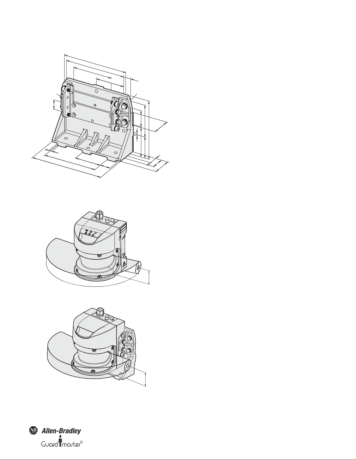
R
11.5.2 Mounting kits
9
80
30
220
160
193.2
175
120
87.5
22.5
67
71
60
46
9
30
183
9
71
66.6
102
51.8
63
102
Figure 69: Dimensional drawing, mounting kit 1, 2 and 3 (mm)
SafeZone™ Safety Laser Scanner User Manual
11.5.3 Scan plane origin
Figure 70: Dimensional drawing of the scan plane (mm)
Figure 71: Dimensional drawing of the scan plane with mounting kit
3 (mm)
Original instructions
10000073050, July 2011 51
Page 54

SafeZone™ Safety Laser Scanner User Manual
Section 12 — Ordering Information
The SafeZone multizone system is made up of the following components:
442L-SFZNSZ Scan head and I/O module — singlezone
442L-SFZNMZ Scan head and I/O module — multizone
442L-CSFZNMZ-X Prewired 13 conductor cable to SafeZone multizone memory module X is either 5 m, 10 m or 20 m
442L-ACRS232 RS232 configuration cable, two meters long or
442L-ACRS232-8 Eight meter RS232 configuration cable
12.1 Delivery
• Sensor head with I/O module mounted 442L-SFZNMZ (multizone) or 442L-SFZNSZ (Singlezone)
• Operating instructions and SCD software CD
• Adhesive label “Important information”
IMPORTANT
System plug without cable and pre-assembled system plug are available from Rockwell Automation.
System connector not in the scope of delivery.
52 10000075030, July 2011
Original instructions
R
Page 55

R
12.2 Accessories and replacement parts
Table 30: Catalog numbers
Description Catalog Number
SafeZone™ Safety Laser Scanner User Manual
Mounting Kit 1: Mounting bracket for direct mounting at the rear on wall or
machine. No adjustment facility.
Mounting Kit 2: Bracket only in conjunction with mounting kit 1. Mounting at the
rear on wall or machine. Longitudinal and cross-wise adjustment possible.
Mounting Kit 3: Bracket only in conjunction with mounting kit 1 and 2. Mounting at
the rear or below on wall, floor or machine. Longitudinal and cross-wise adjustment
possible.
3.0 Amp power supply 1606-XLP72E
USB to serial port adaptor cable 9000USBS
100 meter cable spool 13 conductor 442L-C13GD-S100
Replacement front screen kit 442L-SFZNMZW
442L-AMBSFZNMZ1
442L-AMBSFZNMZ2
442L-AMBSFZNMZ3
Scan head - 4 m 442L-SFZNSZ-SM-A
Scan head - 5 m 442L-SFZNMZ-M-B
I/O module — SafeZone singlezone (1 set) 442L-SFZNSZFMA
I/O module — SafeZone multizone (4 sets) 442L-SFZNMZ-FMB
Unwired memory module 442L-SFZNMZ-MEMA
Original instructions
10000073050, July 2011 53
Page 56

SafeZone™ Safety Laser Scanner User Manual
Section 13 — Annex
13.1 Manufacturer’s checklist
Checklist for the manufacturer/installer for installing electro-sensitive protective equipment (ESPE)
Details about the points listed below must be present at least during initial commissioning~they are, however, dependent on the respective application,
the specifications of which are to be controlled by the manufacturer/installer.
IMPORTANT
Have the safety rules and regulations been observed in compliance with the directives/ standards applicable to the machine Yes
Are the applied directives and standards listed in the declaration of conformity? Yes
Does the protective device comply with the required control category? Yes
Is the access to the hazardous area/hazardous point only possible through the protective safety field of the ESPE? Yes
Have measures been taken to prevent and monitor unauthorized presence in the hazardous area when safeguarding hazardous areas/hazardous points
(mechanical point-of-operation guarding), and have these been secured against removal?
Are additional mechanical protective measures fitted and secured against manipulation which prevent reaching below, above or behind the ESPE? Yes
Has the maximum stopping and/or run-down time of the mac hine been measured, specified and documented (at the machine and/or in the machine
documentation)?
Has the ESPE been mounted such that the required safety distance from the nearest hazardous point has been achieved? Yes
Are the ESPE devices correctly mounted and secured against manipulation after adjustment? Yes
Are the required protective measures against electric shock in effect (protection class )? Yes
Is the control switch for resetting the protective device (ESPE) or restarting the machine present and correctly installed? Yes
Are the outputs of the ESPE (OSSDs) integrated in compliance with the required control category and does the integration comply with the circuit
diagrams?
Has the protective function been checked in compliance with the test notes of this documentation? Yes
This checklist should be retained and kept with the machine documentation to serve as reference
during recurring tests.
No
Ë
Ë
Ë
Ë
Yes
Ë
Ë
Yes
Ë
Ë
Ë
Ë
Ë
Yes
Ë
Ë
Ë
No
Ë
No
Ë
No
Ë
No
Ë
No
Ë
No
Ë
No
Ë
No
Ë
No
Ë
No
Ë
No
Ë
No
Ë
Are the given protective functions effective at every setting of the operating mode sele ctor switch? Yes
Are the switching elements activated by the ESPE, e.g. contactors, valves, monitored? Yes
Is the ESPE effective over the entire period of the dangerous state? Yes
Once initiated, will a dangerous state be stopped when switching the ESPE on or off and when changing the operating mode, or when switching to another
protective device?
Has the information label “Important Information” for the daily check been attached so that it is easily v isible for the operator? Yes
IMPORTANT
54 10000075030, July 2011
This checklist does not replace the initial commissioning, nor the regular inspection by specialist
personnel.
Original instructions
No
Ë
Ë
Ë
Yes
Ë
Ë
Ë
No
Ë
No
Ë
No
Ë
No
Ë
R
Page 57

SafeZone™ Safety Laser Scanner User Manual
R
13.2 Glossary
AOPDDR Active opto-electronic protective device responsive to diffuse reflection (e.g. SafeZone safety laser scanner, see also IEC/
EN 61496-3)
Control Input, static The monitoring cases are switched using the control inputs. The SafeZone safety laser scanner has one static control
input.
External device
monitoring (EDM)
Field set Protective safety field and warning field form a pair, the so-called field set.
I/O module Defines the functionality of the SafeZone safety laser scanner.
Monitoring case A field set (if necessary a simultaneous field set) is allocated to a monitoring case. Monitoring case switching is performe d
OSSD The OSSD output is the switching output on the SafeZone safety laser scanner. This is a semiconductor output and
Protective safety field The protective safety field secures the hazardous area on a machine or vehicle. As soon as the safety laser scanner detects
Reflectivity Reflection of luminance. A measure of the reflectivity is the reflectance defined as the ratio of the luminance
Resolution The minimum size of an object that is acquired by the protective device and is guaranteed by the manufacturer
Restart interlock The restart interlock is a protective device. In certain situations it prevents the machine from automatically
Sensor head Contains the opto-electronic acquisition system.
System plug Contains the configuration memory and all electrical connections. In this way the SafeZone safety laser scanner can
Warning field The warning field is a field with a radius of 49 m. Using this field larger areas can be controlled and simple switching
A means by which the electro-sensitive protective equipment (ESPE) monitors the state of control devices which
are external to the ESPE.
using the control inputs. In this way the SafeZone safety laser scanner can be adapted to the operating mode of the
machine or equipment that it monitors.
is periodically tested for correct function. The SafeZone safety laser scanner has two OSSD outputs that operate in
parallel; for safety reasons these must be evaluated using two channels.
an object in the protective safety field, it switches the OSSDs to the off status and thus initiates the shutdown of the
machine or stop of the vehicle.
reflected from a surface in the measuring direction and the luminance of a completely matt white surface (white
standard).
restarting. This applies, e.g., after the scanner function has triggered during a dangerous machine state, after a
change to the operating mode or the method of activation of the machine, or after the change to the start control
device on the machine.
be easily replaced. After re-commissioning the configuration is loaded from the system plug; the SafeZone
multizone safety laser scanner is then, normally, ready for use.
functions (e.g. warning functions) triggered. The warning field is not allowed to be used for tasks related to the
protection of people.
Original instructions
10000073050, July 2011 55
Page 58

SafeZone™ Safety Laser Scanner User Manual
EC Declaration of Conformity
The undersigned, representing the manufacturer and the authorised representative established within the Community
Rockwell Automation, Inc.
2 Executive Drive
Chelmsford, MA 01824
USA
Herewith declare that the Products: Safezone Safety Laser Scanner
Product identification (brand and
catalogue number/part number):
Product Safety Function: Safezone 442L-SFZ Series safety laser scanners are active opto-electronic protection
are in conformity with the essential requirements of the following EC Directive(s) when installed in accordance with the installation
instructions contained in the product documentation:
2006/42/EC Machinery Directive
2004/108/EC EMC Directive
and that the standards and/or technical specifications referenced below have been applied:
EN 61496-1:2004 + A1:2008 Safety of machinery – Electro-sensitive protective equipment – Part 1: General requirements
IEC 61496-3:2008 Safety of machinery – Electro-sensitive protective equipment – Part 3: Particular
EN ISO 13849-1:2008 Safety of Machinery – Safety related parts of control systems – Part 1: General principles for
EN 62061:2005 Safety of machinery – Functional safety of safety-related electrical, electronic and
EN 61508 Parts 1-7:1998-2000 Functional safety of electrical/electronic/programmable electronic safety-related systems
EN 60204-1:2006 Safety of machinery – Electrical equipment of machines – Part 1: General requirements
Allen-Bradley / GuardMaster 442L-SFZ Series
(reference the attached list of catalogue numbers)
devices responsive to diffuse reflection (AOPDDR). These scanners are non-contact
safety devices and can be used in applications up to Safety Category 3/PL d (EN ISO
13849-1) and SIL2/SIL CL2 (EN 61508 / EN 62061).
and tests
requirements for Active Opto-electronic Protective Devices responsive to Diffuse Reflection
(AOPDDR)
design
programmable electronic control systems
Rockwell Automation BV
Rivium 1e Straat, 23
2909 LE Capelle aan den IJssel
Netherlands
EN 50178:1997 Electronic equipment for use in power installations
EN 61000-6-2:2005 Electromagnetic compatibility – Part 6-2: Generic standards – Immunity for industrial
environments
EN 61000-6-4:2007 Electromagnetic compatibility – Part 6-4: Generic standards – Emission standard for
industrial environments
Conformance of a type sample with the regulations from the EC Machinery Directive has been certified by:
TÜV Rheinland Industrie Service GmbH
Alboinstrasse 56
12103 Berlin, Germany
Manufacturer: Authorised Representative in the Community:
Signature
Name: Daniel L. Nachtigall Name: Viktor Schiffer
Position: Supv – Product Certification Engineering Position: Engineering Manager
Date: 26-Jun-2011 Date: 08-Jul-2011
Document Control Number: SEN-0354-D-EN 1/2
EC Type Examination
Registration No: 01/205/0616/09
Report No: 968/M177.01/09
Signature
56 10000075030, July 2011
Original instructions
R
Page 59

R
Catalogue number Series Description
445L-SFZNSZ Safezone single-zone safety laser scanner
445L-SFZNMZ Safezone multi-zone safety laser scanner
If no series number is given, then all series are covered.
SafeZone™ Safety Laser Scanner User Manual
Original instructions
10000073050, July 2011 57
Page 60

www.rockwellautomation.com
Power, Control and Information Solutions Headquarters
Americas: Rockwell Automation, 1201 South Second Street, Milwaukee, WI 53204 USA, Tel: (1) 414.382.2000, Fax: (1) 414.382.4444
Europe/Middle East/Africa: Rockwell Automation, Vorstlaan/Boulevard du Souverain 36, 1170 Brussels, Belgium, Tel: (32) 2 663 0600, Fax (32) 2 663 0640
Asia Pacic: Rockwell Automation, Level 14, Core F, Cyberport 3, 100 Cyberport Road, Hong Kong, Tel: (852) 2887 4788, Fax: (852) 2508 1846
GuardShield is a trademark of Rockwell Automation, Inc.
Guardmaster is a registered trademark of Rockwell Automation, Inc.
Publication 10000073050, July 2011
Copyright ©2011 Rockwell Automation, Inc. All Rights Reserved. Printed in USA.
 Loading...