

Page 1

Installation Instructions
R
SmartSight DeviceNet PHOTOSWITCH
All Sensors
5-pin micro QD 42GNU- 9220-QD 42GNU- 9020- QD 42GNP-9020- QD 42GNC- 9220- QD
Cat. No.
Optical
Electrical
Mechanical
Environmental
DeviceNet
5-pin mini QD 42GNU- 9220- QD1 42GNU-9020- QD1 42GNP- 9020- QD1 42GNC- 9220 - QD1 42GNR- 9020- QD1 42GNL- 9040 - QD1
2mcable 42GNU- 9220 42GNU- 9020 42GNP- 9020 42GNC- 9220 42GNR- 9020
1 Max. Sensing Distance 4.8m(16ft) 9m(30ft) 1.5 m (5 ft) 1.2 m (4 ft) 129.5 m (425 ft)
2 Field of View
3 Transmitting LED Visible r ed 660 nm Visible red 660 nm Infrared 880 nm Visible red 660 nm Not applicable Infrared 880 nm
4 Sensitivity Adjustment Yes, Learn Button Yes
5 Supply Voltage 1125V DC
6 Current Consumption 75 mA maximum
7 Power Consumption 1.8 W maximum
8 Response Time 3.5 ms 6.5 ms Not applicable
9 Protection Miswire, hot insertion
10 Housing Material Val ox
11 Lens Material Acrylic
12 Indicators SeeTable1 Green: Power
13 Operating Temperature
14 Operating Environment NEMA 4X, 6P, IP67, 8270 kPa (1200 psi) washdown, IP69K
15 Vibration 1055 Hz, 1 mm amplitude, Meets or exceeds IEC 60947--5--2
16 Shock 30 g, meets or exceeds IEC 60947--5--2
17 Relative Humidity 95%
18 Approvals UL, CSA, and CE marked for all applicable directives, ODVA compliant
19 Network Interface DeviceNet
20 Protocol Selectable Change-of-State (COS) and Strobing
21 Operating Mode Selectable Light/Dark Operate
22 Autobaud Detect Selectable ON/OFF
23 Communication Rate Selectable 125 kb, 250 kb, 500 kb
24 Supported Node Address Selectable 063
25 Timer ON delay and OFF delay/one-shot (065,535 ms, 1 or 10 ms time base)
26 Counter Adjustable with output bit (065,535 counts)
27 Motion Detect Adjustable with output bit (065,535 ms, 1 ms time base)
28 Margin Diagnostic Selectable with dual thresholds (0.71.5 and 0.72.0)
29
Margin Diagnostic Type Selectable static or dynamic
Polarized Retroreflective Retroreflective Standard Diffuse ClearSight
1.5_ 1.5_ 3.5_ 1.5_ 1.5_
Photoelectric Sensors
Transmitted Beam
Receiver Source
42GNR- 9020 - QD 42GNL- 9040- QD
-- 2 5 +70_C(--13+158_F)
Not applicable
1
Page 2
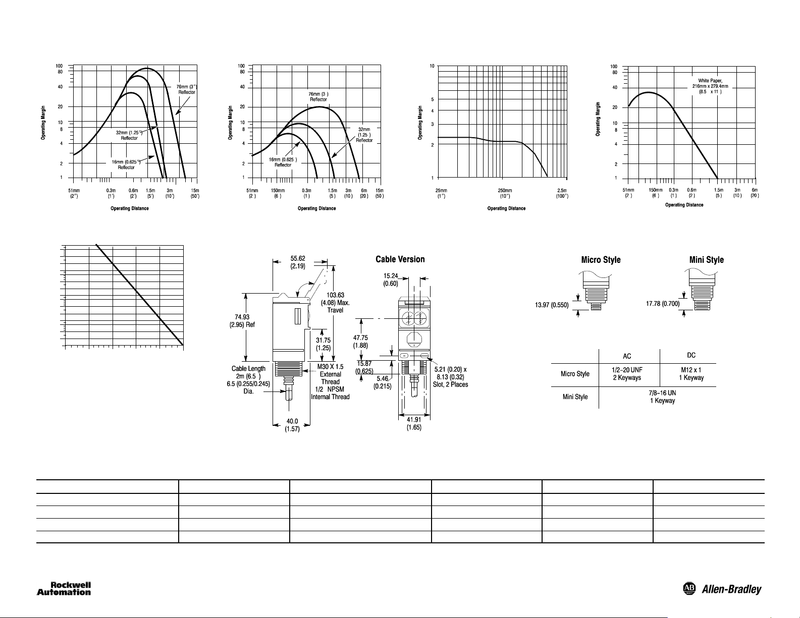
Typical Response Curves
Polarized Retroreflective ClearSight Clear Object DetectorRetroreflective
Standard Diffuse
Transmitted Beam
130m (425ft) Light Source
10000
4000
1000
400
100
40
10
Operating Margin
4
1
0.3
1.8
(1)
(5)3(10)15(50)30(100)
Operating Distance [m (ft)]
130
(425)
Dimensions [mm (inches)]
All Versions Except ClearSightt
Connector Version
Thread Size
Refer to SmartSight DeviceNet catalog pages for ClearSight dimensions.
Accessories [mm (inches)]
Description Cat. No. Description Cat. No. Description Cat. No.
2 m (6.5 ft) mini QD cordset 1485R- P2N5 - C RS--232 PC Interface Module 1770- KFD Reflector, 3 in. Diameter 92- 39
2 m (6.5 ft) mini QD patchcord 1485R- P2N5- M5 RS Networx Software 9357DNETL3 Reflector, 1.5 in. Diameter 92- 47
2 m (6.5 ft) micro QD cordset 1485R- P2R5- C PCMCIA DeviceNet Interface Card 1784- PCD1
2 m (6.5 ft) micro QD patchcord, 90 1485R-P2R5- F5 DeviceNet Handheld Configurator 193- DNCT
2
Page 3

User Interface
Using an instrument screwdriver, open the top cover of the sensor to gain access to the user interface
panel. This panel contains a pushbutton, node-address switches, and LED indicators for configuring and
viewing the sensor’s operation and status. A more complete description of each item is described below.
SmartSightt Sensor—Top View Detail
Node
Address
Pushbutton
A single momentary pushbutton, labeled LRN, is used to “teach” the sensor the application presented to it.
Refer to the Self-Teach in this document for complete instructions on using this feature.
Selector Switches
Two selector switches are provided for setting the sensor node address on the network. Possible addresses
range from 063. The node address may also be set over the network using the RS Networx configuration
tool.
LED Indicators
Three LED indicators are provided to indicate a variety of conditions making it easy for installation and
troubleshooting. The function of each is described in the table below. The LEDs also work together as
indicated on page 5 when used in the self-teach mode.
Table 1. LED Function
Label
Output Yel low ON Target detected
Margin Orange
Network Red/Green
Color State Status
OFF Margin < 2.5
ON Margin 2.5
OFF Sensor not powered
Green ON Steady Sensor active and allocated by master
Green Flashing Sensor active but not allocated by master
Red Flashing Minor correctable fault (baud rate)
Red ON Steady Major fault (possible duplicate address)
Note: LED indicators are used during the Self-Teach operation of the sensor. Refer to the Self-Teach
section for complete instructions on using this feature.
Mounting the Sensor
Securely mount the sensor on a firm, stable, surface or support using one of the many mounting brackets
available from Rockwell Automation/Allen-Bradley. The sensor is supplied with hardware kit #129--130
which contains a plastic mounting nut, lock washer, 2 M5 x 0.8 x 53 screws and nuts. Excessive vibration or
shifting may cause intermittent operation of the sensor.
Hardware Kit
(Supplied)
Wiring the Sensor
Models of SmartSight are available in one of three different connection types as identified in the following
table. Rockwell Automation/Allen-Bradley recommends the use of the 1485R Series of cordsets and
patchcords on the quick-disconnect models.
ATTE N T I O N : All external wiring should conform to the National
Electric Code and all applicable local codes.
Lead Color Cordset Pin Assignment
Designation
V+ Red 2 2
V-- Black 3 3
CAN + White 4 4
CAN -- Blue 5 5
Drain Bare 1 1
2mCable 5-Pin Micro QD 5-Pin Mini QD
5
3
2
1
4
3
Page 4

Configuration
After securing the sensor to a stable surface or support and connecting to the network, it will be necessary
to configure some of the parameters using a suitable network configuration tool such as the Rockwell RS
Networx. For remote configuration the DeviceView Handheld Configurator (193--DNCT) is available. Note
that the node address setting can be set locally using the two switches located on the user interface panel.
The address can also be configured over the network.
Self-Teach Operation
SmartSight DeviceNet photoelectric sensors p rovide self-teach operation for learning the application
presented to it. In essence, it automatically adjusts its sensitivity level to help distinguish between the target
and the background. This feature eliminates the need to manually adjust a sensitivity potentiometer as
found on the earlier DeviceNet 9000 photoelectric sensor. The self-teach can be accomplished either locally
or over the network.
Local Self-Teach
1. Open the top cover of the user interface panel and locate the LRN pushbutton.
2. Press the LRN pushbutton for five seconds to enter the Learn mode. The bi-colored LED will alternate
red/green/red to indicate that this mode is active.
3. To learn condition #1 (background or target), press and release the LRN pushbutton quickly. The Yellow
LED will turn ON.
4. To learn condition #2 (opposite of condition #1), press and release the LRN pushbutton quickly. If the
learn was successful, the yellow LED will turn off then on again. If the sensor was unable to learn the
application, then go to number 6.
5. The sensor will automatically exit the Learn mode and is now ready for operation.
6. If the sensor was unable to establish sufficient contrast difference between the condition #1 and #2
(background and target), the Red LED will turn ON indicating a Learn failure. Try the Learn process
again.
7. If, after a second attempt, the sensor is still unable to learn the application, it indicates that there is
insufficient contrast in the application. Retry the Learn operation using RS Networx as it may be possible
to learn the application by manually setting the sensitivity level over the network.
Remote Self-Teach
Using RS Networx, it is possible to enter the Learn mode to teach the sensor. This process is similar to that
described for the local self-teach and is supplemented with extensive help functions.
ATTE N T I O N : In most retroreflective, polarized retroreflective, and
transmitted beam applications, it is not necessary to
make any sensitivity level adjustments.
Due to the detection method, adjustments may be
required for diffuse sense modes.
Features
Sensor Output Operation Light/dark operate
Timers On,off,motion
Counters One (1) counter
Diagnostics
Margin Analog value
Teach Function Low contrast/sensitivity
Diagnostic mode
Diagnostic margin
Motion detection
Diagnostic Operation
The SmartSight DeviceNet photoelectric sensor provides two independent diagnostic outputs to indicate an
unstable sensing condition. These two diagnostic outputs may be configured to operate in one of two
possible modes. The first, static, is designed for web sensing or other applications in which an immediate
diagnostic output is required. The dynamic operating mode is useful in repetitive applications where targets
are constantly moving into and out of the sensors field of view. In this mode, the output bit will only b e
triggered after detection of seven successive “unstable” signals. This prevents “false triggering” caused by
the leading and trailing edges of the target.
A third diagnostic output bit is also provided. This output will be activated when either the Margin 1 or
Margin 2 diagnostic, or the Motion Detect preset values is reached.
Data Byte 1
0 OFF OK OK OK Motion Less than Preset
1 ON ALARM Margin Unstable Margin Unstable No Motion Preset Reached
PN--28114
10000022881 Ver 00
Printed in USA
Bit 0 Bit 1 Bit 2 Bit 3 Bit 4 Bit 5 Bit 6 Bit 7
Sensor Output Diagnostic Diagnostic Margin 2x Diagnostic Margin 3x Motion Output Counter Output Not Used Not Used
Visit our web site at:
http://www.ab.com/sensors
PHOTOSWITCHRis a registered trademark of Rockwell Automation.
R
Val ox
is a registered trademark of General Electric Company.
4
 Loading...