

Page 1
Installation Instructions
R
RightSightt PHOTOSWITCH
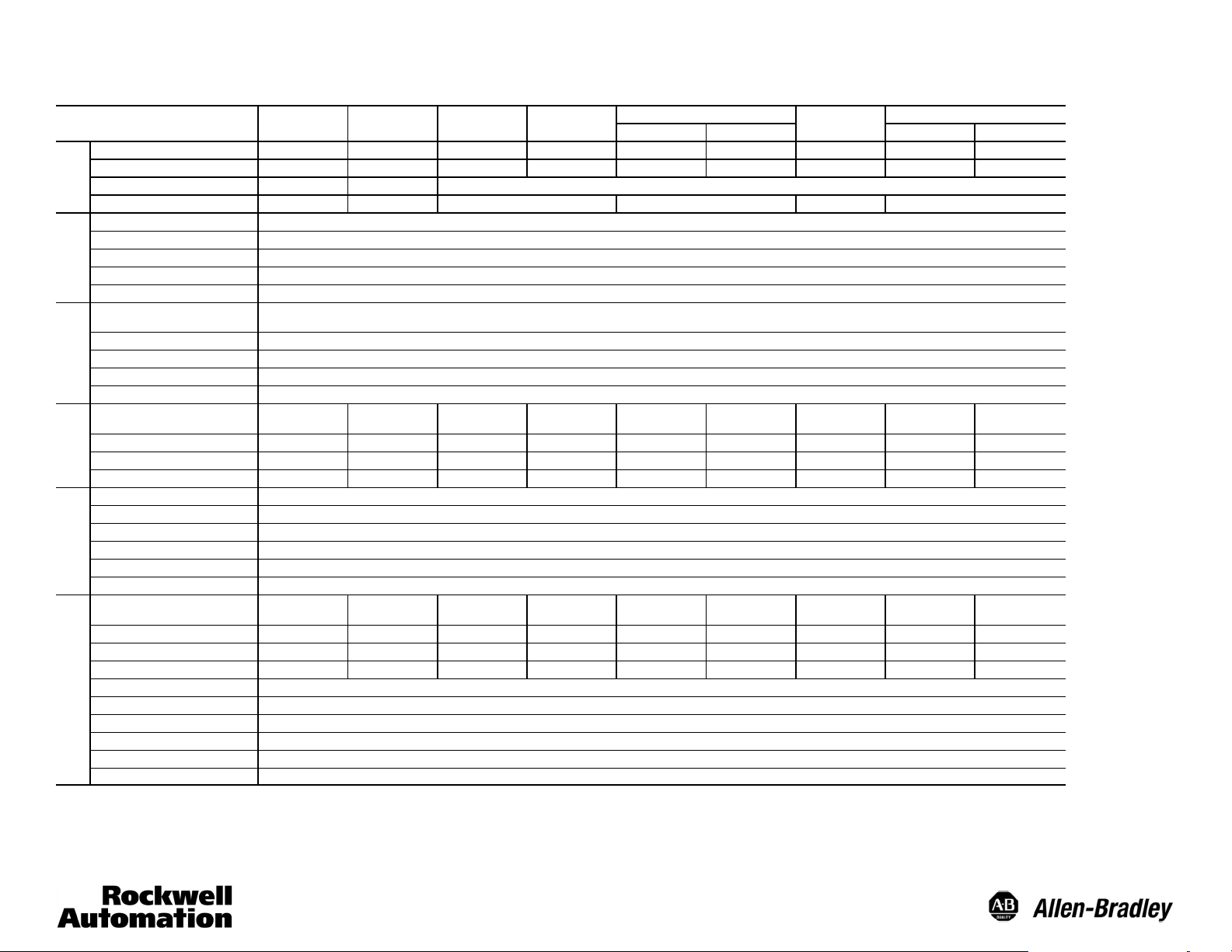
Description
Sensing Distance 3m(9.8ft) 4.5 m (14.7 ft) 500 mm (20 in.) <127 mm (5 in.) 50 mm (2 in.) 100 mm (4 in.) Varies w/FO cable 20 m (60 ft) 4m(13ft)
Field of View 7 2.5 5 7 20 8 Varies w/FO cable 7 7
Transmitted LED Visible Red 660 nm Visible Red 660 nm Infrared 880 nm
Optical
Sensitivity Adjustment no no yes no yes no
Housing/Lens Material Specially formulated polymer/Acrylic
Connection Type Connection Type
LED Indicators See table below
Supplied Accessories One 18 mm mounting nut, two on fiber optic models
Mechanical
Optional Accessories See accessories for mounting brackets, reflectors, apertures, fiber optic cables, cordsets, and patchcords
Operating Temperature
Operating Environment NEMA 3R, 4X, 6P, IP67; 8270 kPa (1200 psi) washdown
Vibration/Shock 5g, 10--55 Hz, 1 mm amplitude, meets or exceeds IEC 947--5--2/30g, 1 ms pulse duration, meets or exceeds IEC 947--5--2
Relative Humidity 95%
Environmental
Certifications UL, CSA, CE for all applicable directives
Catalog Number
Complementary LO & DO NPN
Complementary LO & DO PNP 42EF-P2MPB- a — 42EF-D1MPAK- a 42EF-S1MPA- a 42EF- B1MPBC-a 42EF- B1MPBE- a 42EF- G1MPA- a 42EF - R9MPB- a 42EF - R9MPBV- a
DO NPN & PNP 42EF-P2KBB-a 42EF - U2KBB- a 42EF-D1KBAK- a 42EF- S1KBA- a 42EF-B1KBBC - a 42EF- B1KBBE - a 42EF- G1KBA - a 42EF-R9KBB-a 42EF-R9KBBV- a
DC Sensors
LO NPN & PNP 42EF- P2JBB-a 42EF- U2JBB- a 42EF-D1JBAK - a 42EF- S1JBA- a 42EF-B1JBBC- a 42EF -B1JBBE- a 42EF- G1JBA- a 42EF- R9JBB-a 42EF- R9JBBV- a
Voltage/Current/Power Consumption 10.8 to 30V DC @ 35 mA maximum (1 W maximum)
Sensor Protection Input reverse polarity, over voltage, false pulse prot ected, output short--circuit (SCP) to 100 mA, overload
Output Type NPN, PNP, Dual NPN and PNP
Output Rating 30V DC @ 100 mA maximum (SCP protected)
DC Sensors
Output Leakage Current 0.1 mA maximum
Response Time 1 ms typical, 4 ms for transmitted beam models
Catalog Number
MOSFET, Dark operate output
MOSFET, Light operate output
MOSFET, Dark operate output
MOSFET, Light operate output
Voltage/Current/Power Consumption 21.6 to 264V AC/DC @ 25 mA maximum (1 VA maximum) 21.6 to 132V AC/DC for 42EF--xxxFx--a models
Sensor Protection Input reverse polarity, over voltage, false pulse prot ected, output short--circuit (SCP) to 100 mA, overload
AC/DC Sensors
Output Type Light/dark operate (N.O./N.C.) MOSFET output
Output Rating 264V AC/DC (132V AC/DC for 42EF--xxxFx--a models) @ 100 mA maximum (SCP protected)
Output Leakage Current 0.4 mA maximum
Response Time 8.3 ms typical, 16 ms for transmitted beam models
Provide NPN output when wired as DC circuit. a = (-- A2) 2 m PVC, 300V cable, (--F4) 4 --pin DC micro QD on six-inch pigtail
Provide PNP output when wired as DC circuit. b = (--A2) 2 m PVC, 300V cable, (--G4) 4-- pin AC micro QD on six-inch pigtail
Contact factory for availability of 8 m range receivers.
Transmitted beam source models: 42EF-- E1EZB-- a (DC) and 42EF-- E1QZB--b (AC/DC)
Polarized Retrore-
flective
42EF- P2MNB-a — 42EF-D1MNAK- a 42EF- S1MNA- a 42EF - B1MNBC- a 42EF- B1MNBE- a 42EF- G1MNA- a 42EF- R9MNB- a 42EF- R9MNBV- a
42EF- P2SCB- b 42EF-U2SCB- b 42EF- D1SCAK -b 42EF-S1SCA- b 42EF -B1SCBC- b 42EF - B1SCBE- b 42EF - G1SCA- b 42EF-R9SCB-b 42EF- R9SCBV- b
42EF- P2RCB- b 42EF- U2RCB- b 42EF- D1RCAK- b 42EF-S1RCA-b 42EF- B1RCBC- b 42EF -B1RCBE- b 42EF- G1RCA -b 42EF- R9RCB-b 42EF- R9RCBV- b
42EF- P2SFB-b 42EF-U2SFB- b 42EF - D1SFAK-b 42EF- S1SFA- b 42EF- B1SFBC- b 42EF- B1SFBE- b 42EF- G1SFA- b 42EF-R9SFB- b 42EF- R9SFBV- b
42EF- P2RFB - b 42EF- U2RFB- b 42EF -D1RFAK-b 42EF-S1RFA-b 42EF- B1RCFC- b 42EF-B1RFBE- b 42EF-G1RFA- b 42EF - R9RFB- b 42EF-R9RFBV- b
Standard Retrore-
flective
Diffuse
Sharp Cutoff
Diffuse
-- 2 5 to +55C(--13 to +131F) . 132V AC/DC
-- 2 5 to +70C(--13 to +158F) . 132V AC/DC
Photoelectric Sensors
Background Suppression
50 mm (2 in.) 100 mm (4 in.) 20 m Receiver 4 m Receiver
Glass Fiber Optic
Transmitted Beam
1
Page 2
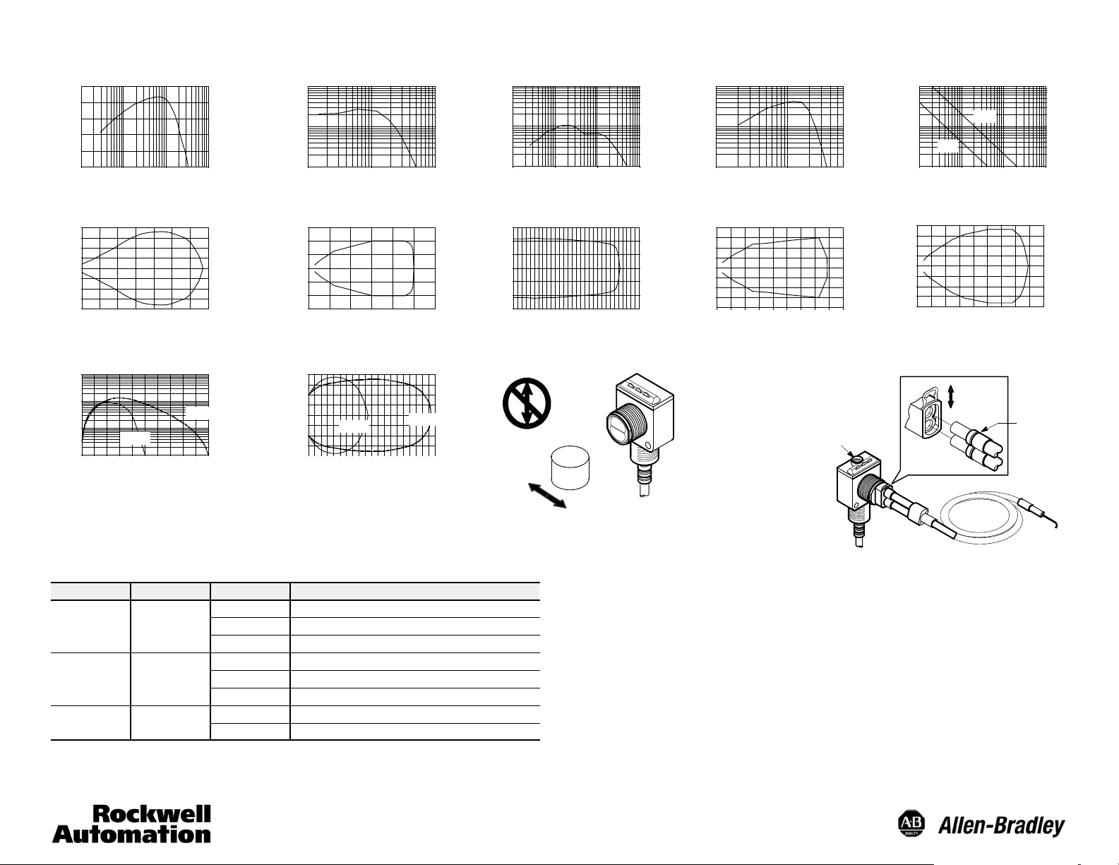
Typical Response Curves
Polarized Retroreflective
6
5
4
3
2
Operating Margin
1
0.01
(0.03)
Distance to 76 mm Reflector, 92 -39 [m (ft)]
Polarized Retroreflective Beam Pattern
20
10
0
-- 1 0
Beam Diameter [mm]
-- 2 0
Background Suppression
1000
100
10
1
Beam Diameter [mm]
0.1
(0.328)
0
1
(3)
20
040
(0.7)
Distance to White Target [mm (in.)]
(3.28)
2
(7)
Distance [m (ft)]
50 mm
(1.5)60(2.3)80(3.1)
10
1
(32.8)
3
(10)
100 mm
100
(3.9)
Standard Retroreflective Diffuse Sharp Cutoff Diffuse
100
10
Operating Margin
1
0.1
(0.328)
Standard Retroreflective
150
100
50
0
-- 5 0
-- 1 0 0
-- 150
Beam Diameter [mm]
0
1
(3.28)
Distance [m (ft)]
1
2
(3)
(7)3(10)4(13)5(16)6(20)
Distance [m (ft)]
10
(32.8)
100
10
Operating Margin
1
0.1
(0.04)
1
(0.4)
Distance to White Target [cm (in.)]
10
(3.9)
Diffuse Beam Pattern
15
5
0
-- 5
Beam Diameter [mm]
-- 1 5
20
040
(8)
(16)
Distance [cm (in.)]
100
(39)
(24)
60
100
10
Operating Margin
1
2.54
(0.1)
Distance to White Target [mm (in.)]
Transmitted Beam—4 m Beam Pattern
0.2
0.1
0
-- 0 . 1
-- 0 . 2
Beam Diameter [mm]
0
1
(3)
Distance [m (ft)]
Background Suppression Beam Pattern
4
2
0
-- 2
-- 4
Beam Diameter [mm]
02
50 mm
1
(3)
(7)3(10)4(13)5(16)6(20)
Distance [mm (in.)]
100 mm
Tar get
25.4
(1.0)
2
(7)3(10)4(13)
Glass Fiber Optic SensorsBackground Suppression Sensors
Sensitivity
Adjustment
Transmitted Beam
100
10
4m
1
0.1
(0.328)
(3.28)
Distance to White Target [m (ft)]
254
(10)
Operating Margin
Transmitted Beam—20 m Beam Pattern
0.5
0.4
0.25
0.12
0
-- 0.12
-- 0.25
-- 0 . 4
-- 0 . 5
Beam Diameter [mm]
5
015
(17)
Distance [m (ft)]
20 m
1
10
(33)
Retaining
Clip
10
(32.8)
(50)
100
(328)
20
(67)
Groove in
end tip
Table 1: LED Function
Label Color State Status
OFF Output de-energized
Output Yel lo w
Margin Orange
Status Green
Note: For DC models, output and margin LEDs alternate flashing when SCP is active.
ON Output energized
Flashing Output SCP active (DC models only)
OFF Margin <2.5
ON Margin >2.5
Flashing Output SCP active (AC models only)
OFF Sensor not powered, output active, SCP active
ON Sensor powered
Note: Due to the detection method, targets traveling horizontal to the sensor’s
optics are detected. Targets traveling vertically may not be accurately detected.
For reliable background suppression, a minimum separation distance of 6 mm
(0.24 in.) is recommended between the target and the backgrounds.
Sensor Alignment
The orange LED is an alignment aid which indicates that a margin of 2.5 has been
reached. This means that the sensor is receiving at least 2.5 times the signal strength
back from the target needed to trigger an output signal. In general, it is desirable to
have a higher margin to help overcome any deteriorating environmental conditions, i.e.,
dust build-up on the sensor’s lens. When aligning the sensor, the best performance can
be obtained if this margin indicator is illuminated with the target in place.
When aligning diffuse mode sensors, ensure that the sensitivity be set at its maximum
setting using the single-turn adjustment knob on the front panel. Pan the sensor left,
right, up, and down to center the beam on the target. It may then be necessary to
decrease this setting to prevent the sensor from detecting a background object. If this
problem persists, the application will require the use of a background suppression,
sharp cutoff diffuse, or retroreflective sensing mode.
2
Page 3

Short-Circuit Protection
RightSight photoelectric sensors provide short-circuit protection (SCP) on the output
leads. This feature is intended to protect the sensor from damage in the event that the
output load is shorted to ground. If this condition does occur, the SCP will activate and
Wiring Diagrams
10.8--30V DC Sensors
Models with Dual NPN and PNP Outputs
Brown
White
Load
Black
Load
Blue
Cable Quick-Disconnect
Models with NPN Outputs
Brown
White
Load
Black
Load
Blue
Cable Quick-Disconnect
Models with PNP Outputs
Brown
Black
Load
White
Load
Blue
Cable Quick-Disconnect
+
–
+
–
+
–
Brown
1
2
White
Load
Black
4
3
1
2
4
3
1
4
2
3
Blue
Brown
White
Black
Blue
Brown
Black
White
Load
Load
Load
Load
Load
Blue
+
124
3
–
DC Micro
+
124
3
–
DC Micro
+
124
3
–
DC Micro
the orange LED wil flash until the source is removed (power must be reset for AC/DC
models). The SCP limits are set to 100 mA over the entire voltage range for both DC
and AC/DC models.
21.6--264V AC/DC Sensors
AC Wiring for 42EF- _ _ _C_ _- _ _ Models
Blue
Black
Load
Brown
Cable Quick-Disconnect
L1
L2
ACWiringfor42EF-___F__-__Models
Brown
Black
Blue
Load
L1
L2
DC Wiring for 42EF- _ _ _C_ _- _ _ Models
Brown
Black
Load
Blue
Cable Quick-Disconnect
DCWiringfor42EF-___F__-__Models
Brown
Black
Load
Blue
2
3
1
+
–
1
3
2
+
–
Red/White
Red
Load
Red/Black
1
3
2
1
3
2
Red/Black
Red
Red/White
Red/Black
Red
Load
Red/White
Red/Black
Red
Red/White
Load
Load
L1
3
4
1
L2
L1
L2
+
3
4
–
1
+
–
2
2
Note: All wire colors on quick-disconnect models shown refer to Allen-Bradley cordsets.
Transmitted Beam Source
AC and DC Wiring
Brown
Blue
Cable Quick-Disconnect
3
L1/+
L2/--
1
2
Red/Black
Red/White
L1/+
L2/--
Page 4

Sensor Dimensions [mm (in.)]
26.5
(1.04)
20.5
(0.81)
34.5
(1.36)
(0.40)
16.5
(0.65)
10
M18 x 1,0
thread
9.6
(0.38)
32.7
(1.29)
(0.16)
19
(0.75)
2m(6.56ft)
4
cable
27
(1.06)
49.7
(1.96)
3.6 (0.145) dia.
clearance for #6--32
screw (2 places)
69
(2.72)
Sensitivity Adjustment
(diffuse and glass
fiber optic only)
18 mm mounting nut
Indicators
10
(0.40)
16.5
(0.65)
(1.36)
20.5
(0.81)
34.5
10
(0.40)
M18x1.0 thread
AC/DC DC
Accessories
Straight Bracket #60--2656 Right Angle Bracket #60--2657 Swivel/Tilt Bracket #60--2649 Apertures
10 Adjustment in
each direction
57.15
(2.25)
28.6
(1.125)
Transmitted Beam and Retroreflective
Sensing Modes only)
9.6
(0.38)
32.7
(1.29)
19
(0.75)
4
(0.16)
27
(1.06)
3.6 (0.145) dia.
clearance for #6--32
screw (2 places)
27.5
(1.08)
46.7
(1.84)
Accessories—Description Catalog Number
Mounting Kit 60- 2716
Clamp Style Bracket 871A- BP18
Flush Mount Adaptor 60- 2590
Field Mount Terminal Chamber—4-pin DC micro 871A- TS4- DM
Field Mount Terminal Chamber—3-pin AC micro 871A - TS3 -RM
Cordset—2 m (6.5 ft), 4-pin DC micro 889D-F4AC- 2
Cordset—2 m (6.5 ft), 4-pin AC micro 889D- F4AEA-2
Reflector—1.25 inch diameter 92- 47
Reflector—3 inch diameter 92 - 39
Fiber optic cable, glass, bifurcated, 5/16 in. threaded 43GR - TBB25SL
Fiber optic cable, glass, individual, 5/16 in. threaded 43FT- TBB25SL
www.rockwellautomation.com
Power, Con trol and Information Solutions Headquarters
Americas: Rockwell Automation, 1201 South Second Street, Milwaukee, WI 53204 USA, Tel : (1) 414.382.2000, Fax : (1) 414.382.4444
Europe/Middle East/Africa : Rockwell Automation, Vorstlaan/Boulevard du Souverain 36, 1170 Brussels, Belgium, Tel : (32) 2 663 0600, Fax (32) 2 663 0640
Paci c : Rockwell Automation, Level 14, Core F, Cyberport 3, 100 Cyberpo rt Road, Hong Kong , Tel : (852) 2887 4788, Fax : (852) 2508 1846
Asia
7.95
(0.31)
50.08
(2.0)
Notes
1. Damage may occur to sensor housing if torque above 20 in-lb is applied to the 18 mm lockout.
2. Fiber optic sensors come with two 18 mm locknuts (75012--025--01). All other RightSight sensors come with
one thick 18 mm locknut (75012--097--01).
3. Optional mounting kit (60-- 2716) comes with two 75012--025--01, one 75012--097--01 locknut, internal tooth
star washer, and screws/nuts for through-hole mounting.
1 mm Qty. 20 #60 --2660
2 mm Qty. 20 #60 --2661
4 mm Qty. 20 #60 --2662
Aperture Set (4 each) #60--2659
Note: 18 mm nut must be installed
prior to installing aperture if threads
on optics snout are to be used.
Publication PA--9705(J)
4
PHOTOSWITCHris a registered trademark of Rockwell Automation.
Visit our web site at www.ab.com.
July 2003
Printed in USA
 Loading...