

Page 1
INSTALLATION INSTRUCTIONS PHOTOSWITCH
RETROREFLECTIVE/DIFFUSE CONTROL, BULLETIN 42DRC-5400
IMPORTANT: SAVE THESE INSTRUCTIONS FOR FUTURE USE. FOR ADDITIONAL INFORMATION REFER TO PUBLICATION PG-9000
BULLETIN NUMBER
PHOTOHEAD POWERBASE
VOLTAGE
SUPPLY
SUPPLY
CURRENT
42DRC- 5400 — — —
OUTPUT CHARACTERISTIC
TYPE RATING LEAKAGE
Analog Voltage 1--10VDC —
Analog Current 1--20mA —
Two
Adjustable Set
Points NPN
42DTB-5000
TERMINAL
42DCB-5000
CABLE
22-- 28
VDC
70mA
SPECIFICATIONS:
Voltage Supply to Analog Output (Terminal 2):
Current Output 40VDC Max............................
Voltage Output 0V....................................
Output Indicators
Setpoint A Red LED...................................
Setpoint B Green LED.................................
Setpoint Adjustment Ye s................................
Setpoint Output Differential 15%.........................
Slope Selectable Positive or Negative.......................
Reverse Polarity Protection Ye s...........................
Transient Noise Protection Ye s...........................
Short Circuit Protection Analog Output only................
Analog Output Calibration Ye s...........................
Sensing Range Adjustment Ye s...........................
Temperature Compensation Yes..........................
Field of View 3........................................
Transmitting LED Infrared, 880nm........................
Operating Environment: NEMA 3, 4, 12, 13, and IP66 (IEC529)
Approvals UL Listed and CSA Certified....................
Housing Material High impact chemically resistant Valox
Ambient Temperature Range -- 4 0
.....
o
Fto150oF(--40oCto65oC)..
Relative Humidity 90%.................................
Te rm i na t io n s
Cable Base: Supplied with 10 (3m) of 5-conductor,..........
flexible, vinyl-covered cable
Terminal Base: Supplied with #6/32 nickel plated brass.......
pressure type terminals
ACCESSORIES
1. Reflector
PAR T NU MB ER SIZE
92-39 3 (78mm)
92-47 1.25 (32mm)
92-46 .625 (16mm)
2. Optional Mounting Assemblies
PAR T NU MB ER DESCRIPTION
60-1577 Armored Cable Adapter
60-1785 Universal Mounting Assembly
60-1748 Heavy Duty Mounting Assembly
60-2014 Flexi-mount Mounting Assembly
60-2083 Photoguard Heavy Duty Protection
60-2213 Conduit Mounting Adapter
60-2230 Limit Switch Type Mounting Assembly
61--5540 NEMA 7 & 9 Enclosure
OPERATING DISTANCE SELECTION
The maximum operating distance is based on installing the control in a relatively clean environment. Normal industrial environment
actually ranges from moderately Dusty to extremely Dirty.
Greater operating margin (excess gain) may be required, which
can be obtained by reducing the operating distance of the control.
(OFF STATE)
RESPONSE
TIME
100ms 2-- 1 5
RETRO TAPE
#7590
15 X15 (.38 X .38)
(.61m--4.57m)
OPERATING DISTANCE
LINEAR
RESPONSE
5-- 1 3
(1.22m--
4.27m)
DIFFUSE
(.15m--
WHITE
PAPER
6-- 5
1.5m)
100mA 10A
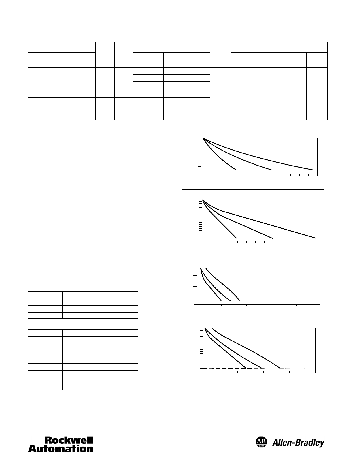
TYPICAL RESPONSE CURVES
RETROREFLECTIVE VOLTAGE OUTPUT
C
4’
(1.2m)5’(1.5m)6’(1.8m)7’(2.1m)8’(2.4m)9’(2.7m)
OPERATING DISTANCE
RETROREFLECTIVE CURRENT OUTPUT
C
4’
(1.2m)5’(1.5m)6’(1.8m)7’(2.1m)8’(2.4m)9’(2.7m)
OPERATING DISTANCE
DIFFUSE VOLTAGE OUTPUT
CALIBRATED BETWEEN:
A
B
C
6’
5’
4’
2’
(.3m)
1’
(.6m)3’(.9m)
(1.2m)
(1.8m)
(1.5m)
OPERATING DISTANCE
DIFFUSE CURRENT OUTPUT
A
0.5’
1.0’
1.5’
2.0’
2.5’
(.3m)
(.45m)
(.6m)
3.0’
(.75m)
(.9m)
OPERATING DISTANCE
A
B
10’
(3m)
A
B
10’
(3m)
A: 1’--5’ (.3m--1.5m)
B: 6” --4’ (15cm--1.2m)
C: 6”--3’ (15cm--.9m)
8’
7’
9’
(2.4m)
(2.1m)
(2.7m)
CALIBRATED BETWEEN:
A: 1’-- 2” (.3m--5cm)
B: 6”--4’ (15cm--1.2m)
C: 6”--3’ (15cm--.9m)
C
B
3.5’
(1m)4’(1.2m)
4.5’
(1.3m)5’(1.5m)
CALIBRATED BETWEEN:
A: 2’--15’ (.6m--4.5m)
B: 2’--10’ (.6m--3m)
C: 2’--6’ (.6m--1.8m)
11’
12’
(3.3m)
(3.6m)
CALIBRATED BETWEEN:
A: 2’--15’ (.6m--4.5m)
B: 2’--10’ (.6m--3m)
C: 2’ --6’ (.6m--1.8m)
11’
12’
(3.3m)
(3.6m)
11’
10’
(3.3m)
(3.6m)
(3m)
5.5’
(1.6m)
DC VOLTAGE
DC CURRENT (mA)
10
9
8
7
6
5
4
3
2
DC VOLTAGE
1
0
10
9
8
7
6
5
4
3
2
1
0
(.6m)3’(.9m)
20
18
16
14
12
10
8
6
4
2
1
0
0
6”
(15cm)
20
18
16
14
12
10
8
6
4
DC CURRENT (mA)
2
1
0
2’
2’
(.6m)3’(.9m)
(.15m)
CALIBRATION PROCEDURES
Before starting the calibration procedures for Analog Output or
Setpoint Output, be sure the control is at the same temperature as it’s
environment; it adjusts after approximately 15 minutes. Setpoint Calibration is best performed after calibration of the Analog Output has
been completed.
13’
(3.9m)
(3.9m)
12’
6.0’
(1.8m)
13’
(4.2m)
(4.2m)
13’
(3.9m)
6.5’
(1.9m)
LINEAR
RESPONSE
2-- 4
(.61m--
1.2m)
14’
15’
(4.5m)
14’
(4.5m)
14’
(4.2m)
7.0’
(2.1m)
15’
15’
(4.5m)
1
Page 2
Calibration of Analog Output
Calibration of the Analog Output is done with a Voltmeter or an
Ammeter. When calibrating the Voltage Output, connect the Voltmeter between Terminal 2 (+) and the negative power supply Terminal 1
(--). Select the Voltmeter Scale for 10VDC.When calibrating the Current Output, install the Ammeter between Terminal 2 (--) and the positive power supply Terminal (+), or the positive of a separate power
supply when used. Select the Ammeter scale for 20mA (DC).
1. With Selector Switches 1 and 2, select Analog Current or Voltage
Output.
2. With Selector Switches 3 and 4, select Diffuse or Retroreflective
operation.
Retroreflective Operation
1. Set retroreflective target at 2 (.61m). Adjust the Analog Output
Calibration pot. for 10VDC or 20mA (2%).
2. Set the retroreflective target at the desired range. 15 (4.57m)
maximum, 5 (1.52m) minimum. Adjust the Sensing Range Adjustment pot. for 1VDC or 1mA (10%).
3. Bring the retroreflective target back to 2 (.61m). Re-adjust the
Analog Output Calibration pot. for 10VDC or 20mA (2%) if
necessary.
4. Place the retroreflective target at the desired range. Re-adjust the
Sensing Range Adjustment pot. for 1VDC or 1mA (10%) if
necessary.
The Analog Output is now calibrated for Retroreflective operation.
Diffuse Operation
1. Place the object to be detected at 1 (.3m). Adjust the Analog
Output Calibration pot. for 10VDC or 20mA (2%).
2. Set the object to be detected back to the desired range, 5 (1.52m)
maximum or 3 (.91m) minimum. Adjust the Sensing Range Adjustment pot. for 1VDC or 1mA (10%).
3. Bring the object to be detected at 1 (.3m). Re-adjust the Analog
Output Calibration pot. for 10VDC or 20mA (2%) if necessary.
4. Place the object to be detected at the desired range. Re-adjust the
Sensing Range Adjustment pot. for 1VDC or 1mA (10%) if
necessary.
The Analog Output is now calibrated for Diffuse operation.
Calibration of Setpoint Outputs
1. Place the retroreflective target at the distance where the Setpoint
Output A is to come on.
2. Adjust the Setpoint pot. A to turn on Output A at this point. (Red
LED turns on.)
3. Place the retroreflective target at the distance where the Setpoint
Output B is to come on.
4. Adjust the Setpoint B to turn on Output B at this point. (Green
LED turns on.)
Note: Be aware that in the retroreflective mode, when setting the
range beyond 11 (3.35m), white paper response may occur
between 1 (2.54cm) and 1 (.3m).
This completes the calibration of Setpoint Outputs.
INSTALLATION
The control must be securely mounted on a firm, stable surface or support. A mounting
which is subject to excessive vibration or shifting may cause intermittent operation.
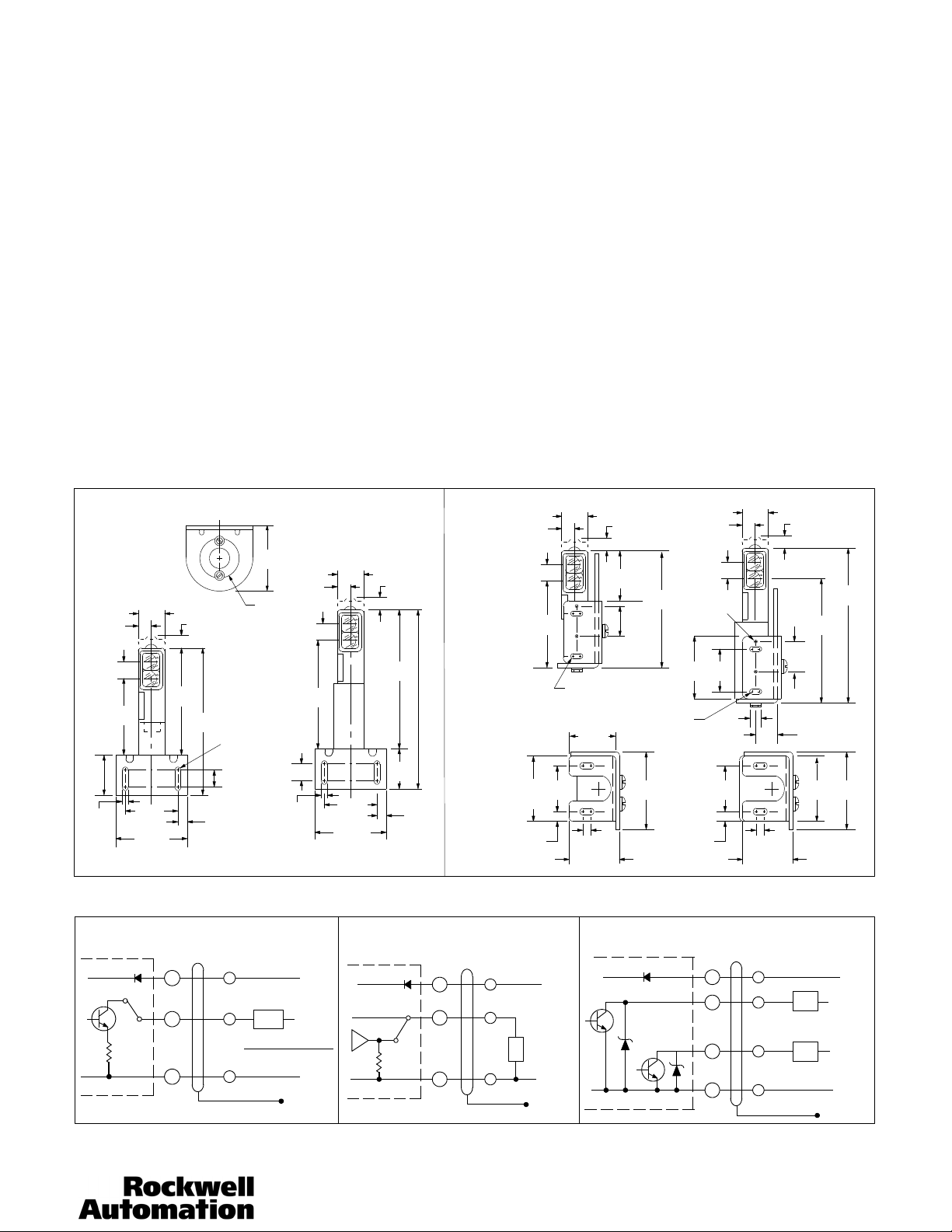
OUTLINE DIMENSIONS
GENERAL PURPOSE
MOUNTING
60-1785
(7.10)
Control with Cable Base
39/64
(15.4)
.280
15/32
(11.9)
27/8
(73.0)
MATERIAL
#11 GA CRS
61/64
(24.2)
2
(50.8)
2 21/32
(67.5)
4.0
(101.6)
11/ 32
(8.73)
57/16
(138.1)
.325
(8.26)
2 57/64
(73.42)
13/4
DIA.
CLEARANCE FOR
#1/4--20 HDW
3/4
3/4
(19.0)
(19.0)
61/64
39/64
(15.4)
.280
(7.10)
15/32
(11.9)
(106.5)
41/4
(24.2)
(50.8)
2 21/32
(67.5)
11/3 2
(8.73)
5 25/64
(136.9)
1 11/16
(42.9)
2
Control with Terminal Base
.325
(8.26)
HEAVY
DUTY MTG.
60-1748
39/64
(15.4)
15/32
(11.9)
5/32
(54.7)
21/64
(8.3)
2 27/32
(72.3)
2
61/64
(24.2)
CLEARANCE
FOR #10-32 HDW
11/2
(38.1)
11/2
(38.1)
1/4 (6.3)
1 14/32
(61.9)
Control with
Cable Base
11/3 2
(8.73)
1 53/64
(46.43)
1
(25.4)
CLEARANCE
FOR #10-32 HDW
21/2
(63.5)
47/64
(104.4)
39/64
(15.4)
#10-32
THREAD
2HOLES
21/2
(63.5)
21/64
(8.3)
15/32
(11.9)
11/4
(31.7)
1/4
(6.3)
11/2
(38.1)
61/64
(24.2)
1/4 (6.3)
1 14/32
(61.9)
Control with
Terminal Base
11/3 2
(8.73)
1
(25.4)
59/64
(23.4)
WIRING
All external wiring should conform to the National Electric Code and applicable local codes. See wiring diagrams for external connectins.
ANALOG CURRENT OUTPUT CONNECTIONS
TERMINAL
BASE
CABLE BASE
RED
+
GRAY
2
RMAX =
BLACK
--
(+) 22-- 28
VDC
CURRENT
SENSOR
(+) 40 VDC
SUPPLY VOLTAGE --
20MA
FLOATING
SHIELD
ANALOG VOLTAGE OUTPUT CONNECTIONS
TERMINAL
BASE
+
MAX
10V
(--)
2
--
CABLE BASE
RED
GRAY
BLACK
(+) 22--28
VDC
VOLTAGE
SENSOR
R=3kOhm
MIN
(--)
FLOATING
SHIELD
NPN SET POINT OUTPUT CONNECTIONS
TERMINAL
BASE
+
3
1
--
CABLE BASE
RED
ORANGE
BLUE
BLACK (--)
LOAD
100mA MAX
LOAD
100mA MAX
4 11/32
(110.3)
25/32
(54.7)
(+)22--28
5 24/32
(146.4)
21/2
(63.5)
VDC
(+)10--30
VDC
(+)10--30
VDC
(--)
FLOATING
SHIELD
2
Publication PA--9169(A)
September 1992
 Loading...