

Page 1
Installation/Configuration Instructions for 42DR
Intrinsically Safe Sensor
IMPORTANT: SAVE THESE INSTRUCTIONS FOR FUTURE USE.
Specifications
Normal Operation Requirements
Voltage Supply 13--29.5V DC
Supply Current 26mA max (output energized) at 13V DC
Response Time 1ms
Dual Outputs 1 NPN open collector (current sink)
Output Ratings 20mA, 29.5V DC maximum
Turn On Pulse Suppression Yes
Light/Dark Energized Option Yes
Reverse Polarity Protection Ye s
Output Overvoltage
Protection w/ Barriers
Field of View Type 42DRU Reflex 2.5
Sensitivity Adjustment Selectable by LOW (L)—HIGH (H) switch.
Ambient Temperature -- 4 0 F to 150F(--40Cto65C)
Relative Humidity 90%
Rated Operating Distances
42DRU- 5500 3 Dia. Reflector #92--39 1 to 30
42DRU- 5700 3 Dia. Reflector #92--39 6 to 15
42DRP- 5500
White Paper
Distance Discrimination Range
Distance differential between surface to be detected and background is defined
as the increase in distance required to de-energize the output, measured from the
point of energization:
Min. differential 10% 6 to 16
Min. differential 20% 2 to 5
42DRA- 5500 Operating distance depended on the choice
30mA max (output energized) at 29.5V DC
1 PNP open collector (current source)
Yes
Type 42DRP Proximity 3
Covers full range of operating distances.
All operating distances are with LOW (L)—
HIGH (H) switch in the HIGH (H) position.
1.25 Dia. Reflector #92--47 1 to 20
0.625 Dia. Reflector #92--46 1 to 15
1.25 Dia. Reflector #92--47 6 to 8
Short Range (SR) Long Range (LR)
1 5
5 to 16 16 to 5
of lens or Fiber Optic Cable. See Bulletin
PA- 8306, PA- 8307, and PA- 8401.
Features (continued)
S Photohead and terminal base are specially keyed to
prevent improper installation of non-intrinsically safe
equipment in a hazardous location.
S Terminal base for input voltages 13 to 29.5V DC eliminates
needs for separate junction box.
S Entity approval:
-- Vmax = 29.5V
-- Imax = 107mA
-- C i = 0 F
-- L i = 0 H
Attention: These parameters must be adhered to. If
!
not, injury may be caused to person or
property.
S Control input parameters
-- Supply voltage 13 to 29.5V DC
-- Supply current, 26mA max. at 13V DC, 30mA max. at
29.5V DC
S Plug-in Photohead contains functional electronics and
optics.
S Thick film microcircuitry for quality and reliability.
S Adjustable input sensitivity.
S RF interference protected.
S No false turn-on pulse.
S Synchronous detection circuitry avoids ambient
interference.
S Switch selection for light or dark operation.
S Dual open collector outputs provide current sink (NPN) and
current source (PNP) capabilities.
-- Load voltage 29.5V DC max.
-- Load current 20mA max.
S Response Time: 1ms
S LED alignment indicator: Visible 360
S NEMA 4X corrosion resistant, high impact housing.
S UL Listed.
Attention: Installation in hazardous environment
locations shall be made according to
!
ANSI/ISA -- RP 12.6 and other applicable
codes and standards.
Features
S For use in Class I, II, III; Division 1, 2; Group A, B, C, D, E,
F, G hazardous locations with Intrinsic Safety Zener Diode
Barriers.
S Reflex, polarized reflex, proximity, and special function
control models.
S Rated operating ranges
-- R e f l e x 1 to 30 (0.03m to 9m)
-- Polarized Reflex 6 to 15 (0.15m to 4.5m)
-- Proximity 0 to 5 (0 to 1.5m).
S Quick-Disconnect (QD) reduces downtime. No disruption of
alignment or wiring.
Attention: Substitution of components may impair
!
intrinsic safety.
Why Intrinsically Safe
Explosion prevention is a prime cons ideration in plants and facilities containing
hazardous atmospheres where “explosion-proof” housings are used.
The main fault with the “explosion-proof” housing system is that a single human
error could create a light explosion probability. Such occurrences as, failing to
tightly replace covers on “explosion-proof” housings, failing to shut off the power
before removing the cover of such a housing, and damaging the machined
surfaces of such covers are all prime examples.
Intrinsically Safe systems are now recognized as a more highly desirable
means of providing automated control functions in explosive environments. The
technique relies on the inherent parameters of electronic circuits, so that no
energy can be released under normal or abnormal operating conditions, of
sufficient magnitude to ignite a specified atmospheric mixture.
Page 2
To design an effective Intrinsically Safe system, energy sources that enter the
hazardous area must be limited. For electronic controls, energy limiting is
accomplished by controlling the voltages and currents that may enter the
hazardous area. In addition, stored electrical energy in the controls is limited to
levels that cannot cause ignition of a given atmosphere.
An Intrinsically Safe system overcomes the shortcomings of the
“explosion-proof” system and virtually eliminates the probability of explosion by
properly installing Intrinsic Safety Zener Diode Barriers in the safe area.
Intrinsic Safety Zener Diode Barriers must be installed in the power supply
line,theload supply line and when using the current source (PNP) open
collector of the Series 5500,inthesignal return line.
Summary of Hazardous Locations
(For full and complete definitions, consult the National Electric Code
publication NFPA No. 70-- 78.)
Class I Locations in which flammable gases or vapors
are or may be present in the air in quantities
sufficient to produce explosive or ignitable
mixtures.
Class II Locations which are hazardous because of the
presence of combustible dust.
Class III Locations which are hazardous because of the
presence of easily ignitable fibers or flyings, but
in which such fibers or flyings are not likely to be
suspended in air concentrations sufficient to
produce ignitable mixtures.
Division I Locations which are hazardous concentrations
in the air exist continuously, intermittently, or
periodically under normal operating conditions.
Division 2 Locations which are hazardous concentrations
are handled, processed, or used but are
normally within closed containers or closed
systems from which they can escape only in
case of accidental rupture or breakdown.
Group A Atmospheres containing acetylene.
Group B Atmospheres containing hydrogen, or gases or
vapors of equivalent hazard, such as
manufactured gas.
Group C Atmospheres containing ethyl-ether vapors,
ethylene, or cyclo-propane.
Group D Atmospheres containing gasoline, hexane,
naptha, benzine, butane, propane, alcohol,
acetone, benzol, laquer solvent vapors, or
natural gas.
Group E Atmospheres containing metal dust, including
aluminum, magnesium, and their commercial
alloys, and other metals of similarly hazardous
characteristics.
Group F Atmospheres containing carbon black, coal or
cake dust.
Group G Atmospheres containing flour, starch, or grain
dusts.
Typical Class I Locations
S Petroleum refineries and gasoline storage and dispensing
areas.
S Industrial firms that use flammable liquids in dip tanks for
parts cleaning or other operations.
S Petrochemical companies that manufacture chemicals from
gas and oil.
S Dry cleaning plants where vapors from cleaning fluids can
be present.
S Companies that have s praying areas where they coat
products with paint or plastics.
S Aircraft hangars and fuel servicing areas.
S Utility gas plants, and operations involving storage and
handling of liquified petroleum gas or natural gas.
Typical Class II Locations
S Grain elevators, flour, and feed mills.
S Plants that manufacture, use, or store magnesium of
aluminum powders.
S Plants that have chemical or metallurgical processes,
producers of plastics, medicines, and firewoods, etc.
S Producers of starch or candies.
S Spice-grinding plants, sugar plants, and cocoa plants.
S Coal preparation plants and other carbon-handling or
processing areas.
Typical Class III Locations
S Textile mills, cotton gins, cotton seed mills, and flax
processing plants.
S Any plant that shapes, pulverizes or cuts wood and creates
sawdust or flyings.
Note: Fibers and flyings are not likely to be suspended in the
air, but can collect around machinery or on lighting fixtures
and where heat, a spark or hot metal can ignite them.
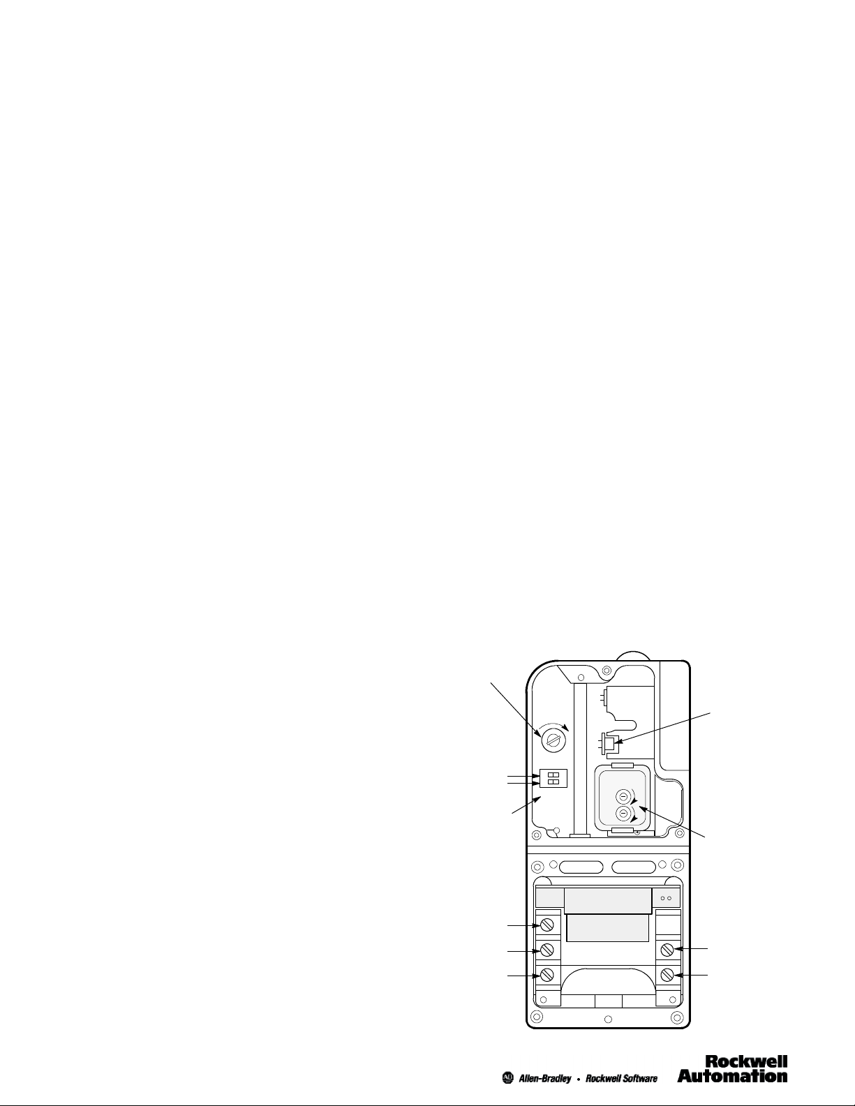
Series 5500 Type 42DRP Photohead and
42DTB Power Base with Covers Removed
Sensitivity
Adjustment
Low - High
Sensitivity
Switch
Light/Dark
Switch
SENS
LO HI
DK LT
TWO - WAY
TIME DELAY
O
N
O
F
F
Visible
Alignment
Indicator
Short Range
Long Range
Shutter
(on 42DRP
only)
PNP & NPN
Output
Circuitry
3
2
1
See page 7, for actual connection diagrams.
(+)
(- )
2
Page 3

Description
Type 42DR Series 5500 QD Intrinsically Safe miniature self-contained
Photoelectric controls each consist of a combination modulated LED light
source, high speed silicon photodetector and dual open collector sold state
outputs which can be used to interface with programmable controllers,
computers, digital control systems or E-M control relays via Intrinsic Safety
Zener Diode Barriers.
The Type 42DR Series 5500 controls are modular in design and consist of two
components—a plug in photohead and a power base which are selected to
suit your functional requirements and assembled together at the point of
installation. The photohead includes a unique Quick-Disconnect feature so that
it can be quickly mounted to or removed from the power base by simply turning
one screw, without disrupting control wiring or alignment. This capability reduces
production downtime and replacement cost and precludes the need for adding
plug and cable assemblies for field disconnect purposes.
Please note that the Series 5500 photoheads and the Series 5500 power base
are keyed so that no other photohead other than the Series 5500 can be
mounted to the Series 5500 power base in a hazardous location. The user
must disconnect the power before removing the quick-disconnect
photoheads or covers.
All Type 42DR Series 5500 (5700) Photoelectric controls must be used
with Intrinisic Safety Zener Diode Barriers.
Photoheads
There are four different photoheads available. For reflex operation (with
retroreflective target), use Type 42DRU Model 5500 which provides an
operating range from 1 to 30.Forpolarized reflex operation (with corner
cube type retroreflective target), use Type 42DRU Model 5700 which provides
an operating range from 6 to 15.Forproximity operation (diffuse reflection
off the object itself), specify Type 42DRP Model 550 which offers an operating
range from 0 to 5. The design of Type 42DRA Model 5500 special function
photohead increases the application capabilities of the control line in difficult
environmental conditions by use of fiber optics and special lens assemblies.
In all models, the photohead contains all the functional electronics and optics. It
includes synchronous detection circuitry which tends to restrict the control to
operate only with its own pulsed LED source. Adjustable input sensitivity
broadens control application capability to those involving translucent and even
transparent materials, such as plastic films and glass. A switch is provided to
assure sensitivity adjustment over the entire control operating range.
With a flick of a switch, the Type 42DR control provides operation in either a
light energized (beam break) or dark energized (beam make) mode.
An optical shutter on the Type 42DRP proximity control permits the use of a
single control for both short- and long-range proximity applications. With the
shutter in the short range (SR) position, the maximum operating distance is 1.
The very sharp drop off in operating margin as shown in the Type 42DRP
response curve on page 6 helps to ignore backgrounds that are close to the
object being detected.
The dual open collector outputs, one an NPN open collector for current sink
and the other a PNP open collector to provide current source, are included in all
Type 42DR controls to maximize customer logic interconnection capabilities.
Therefore, these controls provide the opportunity for simultaneous connection to
relay loads or opto-coupler drives and TTL logic outputs. Seepage7for
connection diagrams.
Ordering Instructions
1. Select Power Base
Base Type
Terminal 13 to 29.5V DC 42DTB- 5500
2. Select Photohead
Operating Mode
Reflex
Polarized Reflex 42DRU- 5700
Proximity 42DRP- 5500
Fiber Optic
Wide Angle
Fixed Focus
3. Select Mounting Assembly
#60--1785 Universal, general purpose, 360 adjustment.
#60--1748 Heavy Duty, for mechanical protection.
#60--2014 Flexi-Mount, for Unistrut mounting on conveyor rails.
#60--2083 Photoguard, #12 gauge cold rolled steel heavy duty protection.
4. Select Intrinsic Safety Zener Diode Barriers
Select Control Drawing on page 7 for wiring diagrams of sourcing and
sinking output configurations. Barrier selection is described below for
each Control Drawing configuration. For installations, to ensure safety
each Barrier must comply with the entity parameters indicated on the
Control Drawing.
In selecting the Intrinsic Safety Zener Diode Barriers, it is important to consider
the resistance of the barrier to ensure operational characteristics in the midst of
inherent barrier voltage drop.
Voltage Supply Type & Model
Output
Characteristics
NPN (Current Sink)
and
PNP (Current Source)
Type & Model
42DRU- 5500
42DRA- 5500
Power Base
Type 42DRU, 42DRP, and 42DRA Intrinsically Safe models 5500 and 5700
Photoheads can be plugged only into a terminal base Type 42DTB Model
5500 suitable for voltage inputs of 13 to 29.5V DC.
The Type 42DTB Model 5500 Terminal Base allowstheusertomakehis
incoming and outgoing connections directly to the control thereby eliminating the
need of a separate junction box. Wiring connections are made to easy-to-wire
pressure type terminals with nonrotating clamps on the screws capable of
handling up to two #14AWG wires.
3
Page 4

Power Supply Barrier
V
Intrinsic safety zener diode barrier #897H-- S120 is recommended for FM
Approved and UL Listed locations. See page 8 for barrier details.
Alternatively, the user must select his own power supply barrier. It should be
noted that the Series 5500 control must have at least 13V DC at the + and -terminals of the power base, Type 42DTB Model 5500. The supply current at
13V DC is 26mA. The maximum barrier resistance is then determined by the
following formula: Vs -- 13
Rb max =
0.026
where:
Rb max = Maximum Barrier Resistance
Vs = Voltage Supply
13 = Minimum Voltage Supply to Control
0.026 = Supply Current (26mA max. at 13V DC)
Load Supply Barrier
Intrinsic Safety Zener Diode Barrier #897H-- S120 is recommended for FM
Approved and UL Listed locations. See page 8 for barrier details.
Alternatively, the user may select his own load supply barrier. When using the
NPN (current sink) open collector output of the Series 5500 Intrinsically Safe
controls, a load supply barrier must be selected in addition to the power supply
barrier. The maximum load supply barrier resistance can be determined by
using the following the formula. The user must provide values for the load
voltage drop, V
Rb max =
max): Vs -- V
, and the load current, I
load
-- 3 . 4
load
I
load
load
(20mA
where:
Rb max = Maximum Barrier Resistance
Vs = Voltage Supply
V1 = Load Voltage Drop
3.4 = Output Cir. Voltage Drop (3.4V)
I
load
= Load Current (20mA max.)
Note: The NPN and output configuration is not approved for
use in hazardous locations classified as Class I, Division 1,
Groups A or B.
where:
Rbps = Max. Power Supply Barrier Resistance
Rbrs = Max. Signal Return Barrier Resistance
Vs = Voltage Supply
load
= Load Voltage Drop
V
13 = Min. Voltage Supply to Control (13V)
0.026 = Supply Current (26mA max. at 13V)
I
load
V
0.4 = Output Switch Voltage Drop (0.4V)
brs
= Load Current (10mA max.)
= Signal Return Barrier Voltage Drop
Installation of Adjacently Mounted Units
Type 42DR Series 5500 Photoheads are supplied to operate at one of two
different frequency ranges, permitting Photoheads to be mounted close to each
other without generating interfering signals.
Units in open frequency range are marked with a dot (S). Units in the other
frequency range have no dot.
Accordingly, when two Type 42DR Series 5500 controls are mounted close
together and/or face each other, select Photoheads so that one is marked with a
dot (S) and the other has no dot.
Alignment
Alignment of the Type 42DR LED control can be accomplished by visually
sighting the control at the reflector using reflex operation or at the object using
proximity until the visible LED indicator on the top lights with switch in the “LT”
position or goes out when the switch is in “DK” position.
To insure that the beam is centered on the reflector, in Reflex or on the object
using proximity, sweep the beam across the reflector or object in the horizontal
plane and determine at what points the indicator light goes on and then goes off.
Set the beam half way between both points. Do the same in the vertical plane.
Signal Return Barrier for Source (PNP) Output Only
Intrinsic Safety Zener Diode Barrier #897H-- S140 is recommended for FM
Approved and UL Listed locations. See page 8 for barrier details.
Alternatively, the user may select his own signal return barrier when the PNP
(current source) open collector output of the Series 5500 Intrinsically Safe
controls. For PNP output applications in hazardous locations not classified as
Class I, Division 1, Groups A and B, signal barrier must be selected in addition
to the power supply barrier and the load supply barrier. For reference, see
Control Drawing for the three barrier PNP output configurations. The sum of the
maximum signal return barrier resistance and the maximum load supply barrier
resistance can be determined using the following the formula. The user must
provide values for the load voltage drop, V
max):
Rbls + Rbrs =
Vs -- (V
load+Vbrs
I
load
+0.4)
, and the load current, I
load
load
(20mA
where:
Rbls = Load Supply Barrier Resistance
Rbrs = Signal Return Barrier Resistance
Vs = Voltage Supply
load
brs
= Load Voltage Drop
= Signal Return Barrier Voltage Drop
= Load Current (20mA max.)
, and the load current, I
is 10mA max in this configuration.
load
Vs -- 13
I
+ 0.026
load
load
Rbps + Rbrs =
I
load
brs
+ 0.026
.
load
+
)
load
V
V
0.4 = Output Switch Voltage Drop (0.4V)
I
load
For PNP output applications in hazardous locations classified as Class I,
Division 1, Groups A and B, signal return barrier must be selected in addition to
the power supply barrier. For reference, see Control Drawing for the two barrier
PNP output configurations. The signal return barrier resistance and the power
supply barrier resistance must satisfy the following two formulas. The user must
provide values for the load voltage drop, V
Please note that I
Rbps = Vs -- (o.4 + V
4
Page 5

Dimensions
ToRemove
Terminal Style Power Base
Photohead
0.109
(2.7)
1.437
(36.5)
1.031
(8.7) Min.
2.797
(71.0)
2.594
(65.8)
2.186
(55.5)
1.437
(36.5)
2.186
(55.5)
Top View Bottom View
Quick
Disconnect
Screw
LED
Indicator
Note: Hardware included with sensor: two (2)
nickel plated 10--32 mounting screws.
0.765
(19.4)
Control with Universal Mounting Assembly #60 -- 1785
Material
#11 GA CRS
1.750
Dia.
2.891
(73.42)
0.953
(24.2)
1.312
(33.3)
0.609
(15.4)
1/2--14
NPSM
0.469
(11.9)
4.250
(106.5)
1.093
(27.7)
0.469
(11.9)
0.453
(15.4)
4.250
(106.5)
10-- 32 UNF
2 Holes
0.953
(24.2)
5.516
(139.5)
0.344
(8.73)
5.391
(136.9)
0.547
(13.8)
1.5
(38.3)
0.328
(8.3)
7.031
(178.59)
Control with Terminal Style Power Base
0.953
2.500
(63.5)
Clearance for
#10-32 HDW
0.469
(11.9)
0.609
(15.4)
#10-32 Thread 2
Holes
1.250
(31.7)
0.250
(6.3)
1.500
(38.1)
0.328
(8.3)
(24.2)
0.250 (6.3)
1.437
(61.9)
0.344
(8.73)
1
(25.4)
(110.3)
0.922
(23.4)
2.156
(54.7)
4.344
5.750
(146.4)
2.500
(63.5)
0.750
(19.0)
0.280
(7.10)
2
(50.8)
2.656
(67.5)
1.687
(42.9)
0.325
(8.26)
5
Page 6

Typical Response Curves
42DRU--5500 Retroreflective
200X
100X
80X
40X
20X
10X
8X
4X
Operating Margin
2X
1X
3
1
(7.62cm)
(2.54cm)
42DRU--5700 Polarized Retroreflective
40X
20X
10X
8X
4X
3X
2X
Operating Margin
1X
0.1
(0.254cm)
1
(2.54cm)
42DRP--5500 Standard Diffuse
100X
80X
40X
20X
10X
8X
4X
Short
Range
0.625 (16mm)
Reflector
1.25 (32mm)
Reflector
6
1
(15.24cm)
(0.3m)
Operating Distance
6
2
(15.24cm)
(5.08cm)
OperatingDistance
2
(0.6m)
(1.5m)
1.25
(32mm)
Reflector
1
(0.6m)
(0.3m)5(1.5m))
5
2
10
(3m)
3 (78mm)
Reflector
20
(6.1m)
(78mm)
Reflector
10
(3m)
8 15
Long
Range
3
20
(6.1m)
50
(15.24m)
(15.24m)
42DRA--5500 Fixed Focus Diffuse
1000
100
10
Operating Margin
1
0.5
(1.27cm)
1
(2.54cm)
5
(12.7cm)
Operating Distance
42DRA--5500 Wide Angle Diffuse
100
0
100
10
Operating Margin
1
0.5
50
(1.27cm)1(2.54cm)
Operating Distance
10
(25.4cm)
20
(50.8cm)
Note 1:
For reliable service in dusty and dirty industrial environments, higher optical
operating margins may be required, resulting in reduced operating range for the
control. Use curves as approximate applications guide only.
Note 2:
42DRA-- 5500 Typical Response curves with glass and plastic fiber optic cables.
See PA--8306.
2X
Operating Margin
1X
0.1
(0.254cm)
1
(2.54cm)
6
(15.24cm)
2
1
(0.6m)
(0.3m)5(1.5m)
10
(3m)
20
(6.1m)
50
(15.24m)
Operating Distance
6
Page 7

Installation Wiring Diagrams for Series 5000 Intrinsically Safe Version
Class I, II, III, Division 1, Group C, D, E, F, G
Class I, II, III, Division 2, Group A, B, C, D, F, G
Photoheads Terminal Base
42DRA-- 5500, 42DRU--5500
42DRP-- 5500, 42DRU--5700
NPN Open Collector Connections (Sinking)
(2 Barriers Required)
Vmax = 29.5V
Imax = 107mA
Sink Wiring
PNP Open Collector Connections (Sourcing)
Vmax = 29.5V
Imax = 107mA
Source Wiring
Ci = 0F
Li = 0H
(3 Barriers Required)
Ci = 0F
Li = 0H
42DTB -- 5500
Terminal BasePhotohead
Terminal BasePhotohead
(+)
(1)
(--)
(+)
(3)
(2)
(--)
Barrier Entity Parameters
AB #897H--S120
Out
Gnd
AB #897H--S120
Out
Gnd
Barrier Entity Parameters
AB #897H--S120
Out
Gnd
AB #897H--S120
Gnd
Out
AB #897H--S140
In
Zener Diode Barriers
Barrier Bus
(less than 1 ohm)
Barrier Bus
(less than 1 ohm)
Nonhazardous LocationHazardous Location
In
Gnd
Earth Ground
In
Gnd
In
Gnd
Earth Ground
Gnd
In
Out
Power Supply
& Load Circuits
Power Supply
Supply Return
Power Supply
Load Supply
Load
Supply Return
Load
24V DC 8%
Load
Supply
( +5V DC)
TTL
Device
Signal
Return
(+)
(+)
(+)
(--)
24V DC 8%
(+)
(+)
(--)
Gnd
Class I, II, III, Division 1, Group A, B, C, D, E, F, G
Class I, II, III, Division 2, Group A, B, C, D, F, G
PNP Open Collector Connections (Sourcing)
(2 Barriers Required)
Vmax = 29.5V
Imax = 107mA
Source Wiring
Notes:
Installation must be in accordance with the National Electrical CodeR (NFPA 70, Article 504), ANSI/ISA--RP12.6, and the manufacturer ’s instructions.
Barrier entity parameters: Voc 29.5V; Isc 107mA; Ca Ccable; La Lcable; recommended barriers are indicated on the above wiring diagram.
If the electrical parameters of the cable used are unknown, the following values may be used: Capacitance -- 60pF /ft.; Inductance -- 0.20H/ft.
Barrier bus must be insulated from other grounded metal. Use DIN Rail Mounting Kit, Allen-Bradley #64--136.
Maximum nonhazardous area voltage must not exceed 250V.
An approved dust tight seal is required for Class II, III applications.
The output circuits of Zener Diode Barriers shall be in separate cables or separated from each other per NEC 504--30.
No revision to drawing without prior UL approval.
Ci = 0F
Li = 0H
(+)
(3)
(2)
(--)
Terminal BasePhotohead
Barrier Entity Parameters
AB #897H--S120
Out
Gnd
AB #897H--S140
In
Gnd
Barrier Bus
Gnd
In
Gnd
Earth Ground
(less than 1 ohm)
Out
Gnd
Power Supply
Supply Return
Load
10mA Max.
24V DC 8%
Signal
Return
(+)
(--)
Allen-Bradley Control Drawing #133--451(Ver 08)
7
Page 8

#897H--S120 and #897H--S140 Intrinsic Safety Zener
w
Diode Barrier Information Specifications
Environmental Conditions
Operating Temperatures -- 4 0 to 122F(--40Cto+50C)
Storage Temperature -- 4 0 F to 167F(--40Cto+75C)
Relative Humidity 5% to 95% noncondensation
Vibration Resistance
Vibration Frequency 55Hz
Vibration Amplitude +1.5mm (+0.062in)
Shock Resistance 20g
Operational Data, Safety Barrier #897H- S120
Input Voltage—Rated
Internal Resistance—Typical
—Tolerance
Replaceable Fuse
#23- 155 Rating
Leakage Current Micro A
Short Circuit Protection Yes
Division 1, 2
Groups AtoG
Operational Data, Safety Barrier #897H- S140
Input Voltage—Rated
Voltage Drop Resulting from
Internal Impedance—Typical
—Tolerance
Replaceable Fuse
#23- 156 Rating
Leakage Current 10A
Short Circuit Protection Yes
Division 1, 2
Groups AtoG
Mounting Accessories
#63- 112 Plastic Mounting Adaptor for Barriers #897H - S120 and #897H- S140
to fit #64- 134 or other EN50022/DIN46277 Mounting Rail.
#64- 134 1m (3.3ft) prepunched zinc plated and chromated steel Mounting Rail
per EN50022/DIN46277 (TS35)
+24V
—Max
+26V
302
+16
80mA
Class I, II, III
+24V
—Max
+26V
1V
1V @ < 22mA
2V @ > 22mA
100mA
Class I, II, III
Description
Intrinsic Safety Zener Diode Barriers #897H-- S120 and #897H--S140)are
passive protective interface assemblies to isolate intrinsically safe circuits from
non-intrinsically safe circuits as defined in FM Class No. 3610.
Intrinsically safe connections are suitable for hazardous locations classified as:
Class I, II, III
Division 1 or 2
Groups A, B, C, D, E, F, G.
The Intrinsic Safety Zener Diode Barrier offer economical solutions for
instrumentation and control systems in hazardous locations defined by NEC
Article 500.
Principle of the Replaceable Keyed Fuse Assemblies
For the Intrinsic Safety Zener Diode Barriers #897H --S120 & #897H--S140, the
principle of a keyed fuse assembly has been employed. In case of a fault due to
overvoltage, polarity misconnection or transients, only the protective keyed fuse
assembly needs to be replaced. Disassembly, disconnection of the wiring, or
even disposing of the entire barrier is eliminated, thus providing a very
economical solution for application of Intrinsic Safety Zener Diode Barriers.
The protective fuse is securely embedded in a keyed fuse assembly. This keyed
assembly is coded for a defined fuse rating. Only the properly rated keyed fuse
assembly is able to be inserted in the appropriate barrier.
The replacement of the fuse assembly can be done by the user at the job site.
The barriers do not have to be returned to the manufacturer for replacement.
See Operational Data for #897H-- S120 and #897H--S140 in Specifications for
proper Replaceable Fuse selection.
12
#897H--S120 or #897H--S140
Intrinsic Safety
Zener Diode Barrier
with Replaceable Fuse
(102)
160mA
160mA
160mA
4
160mA
Intrinsic
Safety
Barrier
34
0.5
(12.5)
2.1875 (56)
DIN Rail Mounting Hole Spacing
4
(102)
2.75
(70)
3.75
(93.5)
#64--134 TS35 DIN Mounting Rail
ww.rockwellautomation.com
Power, Control and Information Solutions Headquarters
Americas: Rockwell Automation,1201 South Second Street, Milwaukee, WI 53204-2496 USA, Tel: (1) 414.382.2000, Fax: (1) 414.382.4444
Europe/MiddleEast/Africa: Rockwell Automation, NV,Pegasus Park, De Kleetlaan 12a, 1831 Diegem, Belgium, Tel: (32) 2 663 0600, Fax(32) 2 663 0640
Asia Pacific: Rockwell Automation, Level 14, Core F, Cyberport 3,100 CyberportRoad, Hong Kong, Tel: (852) 2887 4788, Fax: (852) 2508 1846
Publication 42DR-- IN001A--EN--P
July 2013
E 2013 Rockwell Automation, Inc. All rights reserved. Printed in USA.
PA--8701(Ver 06)
8
 Loading...