

Page 1
INSTALLATION INSTRUCTIONS PHOTOSWITCH
BACKGROUND SUPPRESSION CONTROL WITH TIMING, BULLETIN 42DBS-5100
IMPORTANT: SAVE THESE INSTRUCTIONS FOR FUTURE USE. FOR ADDITIONAL INFORMATION REFER TO PUBLICATION PG-9000
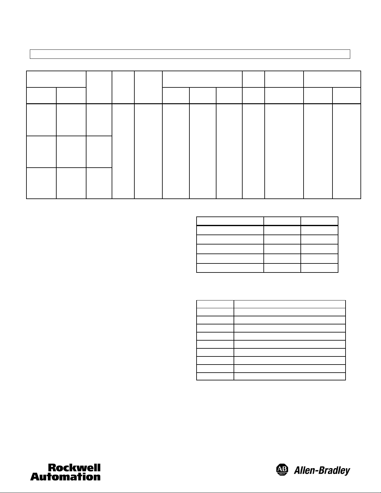
BULLETIN NUMBER OPERATING
PHOTOHEAD POWERBASES
42DBS-5100 — TIMING
42DTB-5000 —
42DCB-5000 —
MODE
VOLTAGE
SUPPLY
10--30
VDC
CURRENT
SUPPLY
TYPE RATING LEAKAGE
40mA MAX NPN & PNP
SPECIFICATIONS:
Range Adjustment Fine and Coarse........................
o
Ambient Temperature Range -- 4 0
Fto150oF(--40oCto65oC)..
Relative Humidity 90%.................................
Turn on Pulse Suppression Ye s...........................
Reverse Polarity Protection Ye s...........................
Output Overload and Short Circuit Protection Ye s...........
Field of View 3
........................................
Transmitting LED Infrared, 880nm........................
Margin and Alignment Indicator with 3 Indicating Modes
-- R e d Output Energized................................
-- Green 2XMargin...................................
-- F l a s h i n g G r e e n Over Current..........................
Lens Material Acrylic...................................
Operating Environment NEMA,3,4,12,13andIP66(IEC529).
Approvals UL Listed and CSA Certified....................
Housing Material High impact chemically resistant VALOX
...
Cable Base Suppliedwith10 (3m) of 5 conductor, flexible,.....
vinyl-covered cable.
Te rm i na t io n Supplied with #6/32 nickel plated brass..........
pressure type materials
OUTPUT CHARACTERISTIC RESPONSE
(OFF STA TE)
100mA AT
10--30 VDC
1A 5ms
TIME
Timing Ranges
TIMING RANGE (SECONDS) SHORT LONG
On/Off Delay 0--1.5 0--15
On Delay 0--1.5 0--15
Off Delay 0--1.5 0--15
o
One Shot 0--1.5 0--15
Delayed One Shot 0--1.5 0--15
ACCESSORIES
Optional Mounting Assemblies
PAR T NU MB ER DESCRIPTION
60-1577 Armored Cable Adapter
60-1785 Universal Mounting Assembly
60-1748 Heavy Duty Mounting Assembly
60-1840 Right Angle Mirror
60-2014 Flexi-mount Mounting Assembly
60-2072 PHOTOcountSWITCH Totalizer
60-2083 Photoguard Heavy Duty Protection
60-2213 Conduit Mounting Adapter
60-2230 Limit Switch Type Mounting Assembly
SUPPRESSION POINT
ADJUSTMENT RANGE
2.5-- 1 2
(6.3cm--30.5cm)
TYPICAL SUPPRESSION QUALITY
WHITE BACK-
GROUND
CONTROL OFF
2.5
(6.35cm)
4
(10.1cm)
6
(15.2cm)
8
(20.3cm)
10
(25.4cm)
12
(30.5cm)
BLACK
TARG ET CON -
TROL ON
2.3
(5.89cm)
3.9
(9.9cm)
5.8
(14.7cm)
7.7
(19.5cm)
9.5
(24.1cm)
10.5
(26.6cm)
1
Page 2
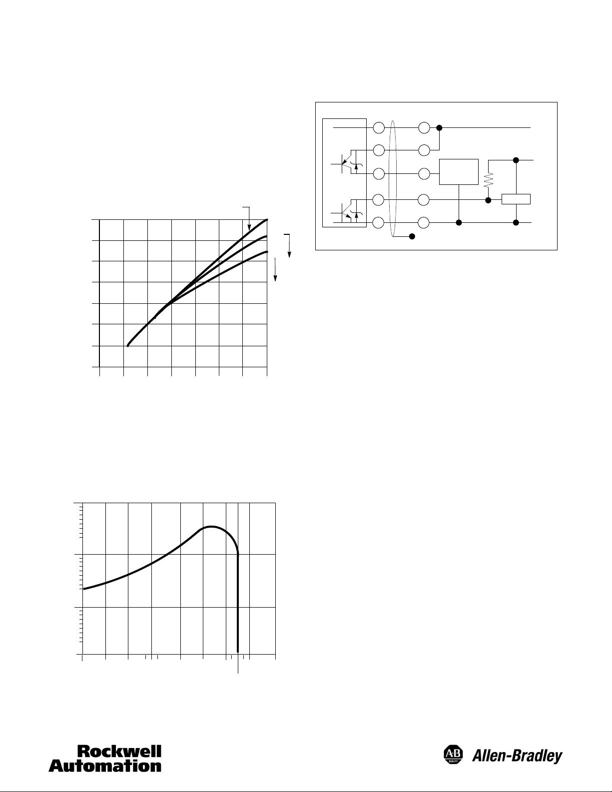
OPERATING MARGIN
1. The operating margin is parenthesis are for diffuse white surfaces
that fill the control’s field of view.
2. 6.1% and 2.6% designate dark colored surfaces having diffuse re-
flectance of 6.1% and 2.6% respectively compared to diffuse white.
3. The 2.6% surface is Krylon # 1602 Ultra flat black.
TYPICAL SUPPRESSION CURVE
WHITE PAPER
14
(35.5cm)
12
(30.5cm)
10
(25.4cm)
8
(20.3cm)
6
(15.2cm)
(10.1cm)
(5.08cm)
4
2
0
0 2
(5.08cm)4(10.1cm)6(15.2cm)8(20.3cm)
10
(25.4cm)
12
(30.5cm)
DISTANCE TO SENSED OBJECT
14
(35.5cm)
6.1%
2.6%
(OPERATING MARGIN) M - 38
DISTANCE TO BACKGROUND OBJECT
TYPICAL RESPONSE CURVE
SUPPRESSION SET FOR 8 (20.3CM)
1000x
100X
10X
OPERATING MARGIN
1X
.1”
(.254cm)
.3”
(.762cm)
.5”
(1.27cm)
.8”
(2.032cm)2”(5.08cm)4”(10.16cm)6”(15.24cm)
OPERATING DISTANCE
8”
(20.3cm)
10”
(25cm)
12”
(30cm)
WIRING
All external wiringshould conformto theNational ElectricCode and
applicable local codes. See wiring diagrams for external connections.
TYPICAL WIRING DIAGRAMS
(OPERATING MARGIN) M- 16
TERMINAL BASE
ALIGNMENT
+
3
2
1
--
CABLE BASE
Red
Orange
Grey
Blue
Black
Floating Shield
Programmable
Controller
DC Interface
1. Loosen lock to allow sensing range adjustment.
2. Adjust “Coarse” sensing range adjustment to the maximum position (full counterclockwise position)
3. Set “Light Energized” (LT)/“Dark Energized” (DK) switch to the
Light Energized position.
4. Select short (0--1.5sec) or Long (0--15sec) “off delay” (one-shot)
switch.
5. Select short (0--1.5sec) or Long (0--15sec) “on delay” (one-shot)
switch.
6. Select “Time delay” (TD) or “One-Shot” (OS) operation switch .
7. Set the on time to minimum, with the on-timing pot. (full counter
clockwise)
8. Set the off-time to maximum, with the off-timing pot, when in
short-off mode (full clockwise) or to at least 2--3 seconds, when
in long-off mode.
9. Turn “coarse” sensing range adjustmentto the minimum position
(full clockwise).
10. Position the control in its application and increase the sensing
range until the control senses the background. The Red LED indicator will turn On. The Green LED (2X margin indicator) will
probably turn On.
11. With the “fine” adjustment, decrease the sensing range until the
Green LED turns Off.
12. Place the object to be detected in front of the control at the expected sensing distance. Both red and green LED’s should turn
On. Remove the target.
13. Time Delay Operation -- If after the off delay has elapsed the
Red LED indicator turns Off, the control has the correct adjustments and settings should be locked with the lock screw. If
the Red LED does not turn Off, slightly reduce the sensing
range with the fine sensingrange adjustmentand repeat steps
12 and 13.
14. One-Shot Operation -- Replace the target in front of the control
after the one shot time has elapsed. If the Red LED turnsOn,
the settingsare correctand can be locked with the lock screw.
If the Red LED does not turn On, slightly reduce the sensing
range with the fine sensingrange adjustmentand repeat steps
12 and 14.
(+)
10--30VDC
+5VDC
TTL Logic
(--)
22
Page 3

15. Select Light or Dark operate mode with switch.
16. Adjust for the desired delays with the On and Off timing pots.
17. Tighten the lockscrew after adjusting the sensing range. A slight
increase in sensing distance may occur. Typically .25 (.63cm) at
12 (30.5cm), .12 (30.5cm) at a 6 (15.2cm) and .062 (1.57cm)
at 3 (7.62cm), for both background and target. If necessary,
sensing range variation can be compensated for by adjusting to
11.75 (29.8cm) for a 12 (30.5cm) suppression point, 5.875
(14.9cm) for a 6 (15.2cm) suppression point, and 2.95
(7.46cm) for a 3 (7.62cm) suppression point. Repeat steps 5 and
6 to verify the range after the lockscrew is tightened.
APPLICATION PRECAUTIONS
To obtain the high sensitivity and sharp cut-off required in a background suppression control, two photodetectors are used. One detector senses objects in close, the other detector will sense further out.
If the further out signal (background) is greater than or equal to
the close in signal, the control remains Off, if the close signal is greater than the background signal, the control output will turn On.
This interdependence of the two photodetectors and overlapping
sensing areas require that the object being sensed passes by the sensor
in certain directions or false operation could occur. Therefore, an object always should travel on an x-axis perpendicular with the control.
See figures below.
CLOSE SENSING
AREA
FIELD OF VIEW
OVERLAP
Direction
of travel
SUPPRESSION
POINT
OBJECT
SUPPRESSED
FAR SENSING
AREA
TO BE
WRONG DIRECTION OF TRAVEL CORRECT DIRECTION OF TRAVEL
INSTALLATION
The control must be securely mounted on a firm, stable surface or
support. A mounting which is subject to excessive vibration or shifting may cause intermittent operation.
OUTLINE DIMENSIONS
Control
Top Vi ew
Suppression
Point
Direction
of travel
OBJECT
TO BE
SUPPRESSED
Both
sensing ranges
overlap
61/64
(24.2)
15/16
(33.3)
15/32
(11.9)
39/64
(15.4)
5 33/64
(139.5)
QUICK
DISCONNECT
SCREW
LED
INDICATOR
1/2--14
NPSM
15/64
(27.3)
10--32 UNF
2HOLES
49/64
(19.4)
35/64
(13.8)
17/16
(36.5)
11/2
(38.1)
21/64
(8.3)
25/32
(54.7)
1 17/16
(36.5)
25/32
(54.7)
TO REMOVE SCANNER
11/32
(8.7)MIN.
7/64
(2.7)
2 51/64
(71.0)
2 19/32
(65.8)
25/32
(54.7)
21/64
(8.3)
11/2
(38.1)
3/4
(19.0
)
TERMINAL BASE CABLE BASE
33
10-32 UNC
15/64
(27.3)
2HOLES
1/4-18
NPSM
39/64
(15.4)
1/4-18
NPSM
15/32
(11.9)
27/8
(73.0)
61/64
(24.2)
3 63/64
(101.2)
7/64
(2.7)
10’ (3m)
CABLE
Page 4

MOUNTING ASSEMBLIES
w
39/64
(15.4)
.280
(7.10)
15/32
(11.9)
27/8
(73.0)
GENERAL PURPOSE MOUNTING
60-1785
MATERIAL
#11 GA CRS
61/64
(24.2)
(50.8)
2 21/32
(67.5)
11/3 2
(8.73)
4.0
(101.6)
57/16
(138.1)
CLEARANCE FOR
#1/4- -20 HDW
3/4
(19.0)
2
.325
(8.26)
2 57/64
(73.42)
13/4
DIA.
3/4
(19.0)
39/64
(15.4)
.280
(7.10)
15/32
(11.9)
(106.5)
41/4
61/64
(24.2)
2
(50.8)
2 21/32
(67.5)
11/ 32
(8.73)
5 25/64
(136.9)
1 11/16
(42.9)
.325
(8.26)
39/64
(15.4)
15/32
(11.9)
2 27/32
(72.3)
(54.7)
5/32
21/64
(8.3)
61/64
(24.2)
FOR #10-32 HDW
2
11/2
(38.1)
CLEARANCE
11/2
(38.1)
1/4 (6.3)
1 14/32
(61.9)
HEAVYDUTYMOUNTING
60-1748
11/3 2
(8.73)
1 53/64
(46.43)
47/64
(104.4)
1
(25.4)
21/2
(63.5)
CLEARANCE
FOR #10-32 HDW
21/2
(63.5)
15/32
(11.9)
39/64
(15.4)
#10-32
THREAD
2HOLES
11/4
(31.7)
21/64
(8.3)
1/4
(6.3)
11/2
(38.1)
61/64
(24.2)
1/4 (6.3)
1 14/32
(61.9)
11/3 2
(8.73)
(25.4)
1
4 11/32
(110.3)
59/64
(23.4)
25/32
(54.7)
5 24/32
(146.4)
21/2
(63.5)
Control with Cable Base
Control with Terminal Base
Control with Cable Base Control with Terminal Base
ww.rockwellautomation.com
Power, Control and Information Solutions Headquarters
Americas: Rockwell Automation, 1201 South Second Street, Milwaukee, WI 53204-2496 USA, Tel: (1) 414.382.2000, Fax: (1) 414.382.4444
Europe/Middle East/Africa: Rockwell Automation NV, Pegasus Park, De Kleetlaan 12a, 1831 Diegem, Belgium, Tel: (32) 2 663 0600, Fax (32) 2 663 0640
Asia Pacific: Rockwell Automation, Level 14, Core F, Cyberport 3, 100 Cyberport Road, Hong Kong, Tel: )852) 2887 4788, Fax: (852) 2508 1846
Publication PA--9168(A)
March 1992
44
 Loading...