

Page 1
Installation Instructions—PHOTOSWITCHRSeries 5000 Blue Line with Analog Output
Photo Head Retroreflective Standard Diffuse Fixed Focus Wide Angle
Catalog Number 42DRU--5400 42DRP- -5400
Sensing Distance
Transmitting LED Infrared 880nm Infrared 880nm (42DRA) Infrared 880nm (42DRF) Visible Red 660nm Infrared 880nm Visible Red 660nm
Indicators Red: Setpoint A; Green: Setpoint B
Field of View
Sensitivity Adjustment Yes
Operating Temperature
Relative Humidity 90% maximum
Housing/Lens Material Valox/Acrylic Valo x/Acrylic
Cover Gasket Material Nitrile
Operating Environment NEMA 3, 4, 12, 13, and IP66 (IEC 529), corrosion resistant, high-impact housing
Approvals UL listed, CSA certified (except cable style power base), and CE marked for all applicable directives
Protections Output short-circuit (analog only)
Vibration 10--55 Hz, 1 mm amplitude, Meets or exceeds IEC 947--5--2
Shock 30G, Meets or exceeds IEC 947--5--2
Supply Voltage/Current 22--28V DC/70mA max
Output Type Analog 1--20mA current or 1--10V DC voltage (selectable negative or positive slope) (2) NPN setpoints (selectable)
Output Load 900 (analog current); 3K minimum (analog voltage); 28V DC, 100mA (setpoints)
Load Current 100mA
Leakage Current 10Amax.
Response Time 100ms (time required for analog swing)
4.6m (15ft) total
4.0m (13ft) linear
3_ 3_
1.5m (5ft) total
1.2m (4ft) linear
42DRA- -5400--FF
42DRF--5400--FF
(IR) 127mm (5in) max peak @ 3in
(VR) 101.6mm (4in) max peak @ 2in
— — Depends on fiber optic cable selected
-- 4 0 _Cto+65_C(--40_Fto+150_F)
42DRA--5400--WA
42DRF--5400--WA
(IR) 508mm (20in)
(VR) 177.8mm (7in)
Infrared Glass
42DRA--5400--FO
42DRF--5400-- FO
Depends on fiber optic cable
Photo Base
Fiber Optic
Screw Terminal (nickel-plated brass
pressure type terminal #6-- 32
3m Cable (5 conductor flexible PVC
jacketed cable 3m (10ft))
42DTB--5000
42DCB--5000
Fiber Optic
Visible Red Plastic
Sensing modes may be field configurable by selecting either the 42DRA-- 5400 or 42DRF--5400 photohead and one of the following lens assemblies: 61--5551 for fixed focus sensing mode, 61--5511 for wide angle diffuse sensing
mode.
1
Page 2
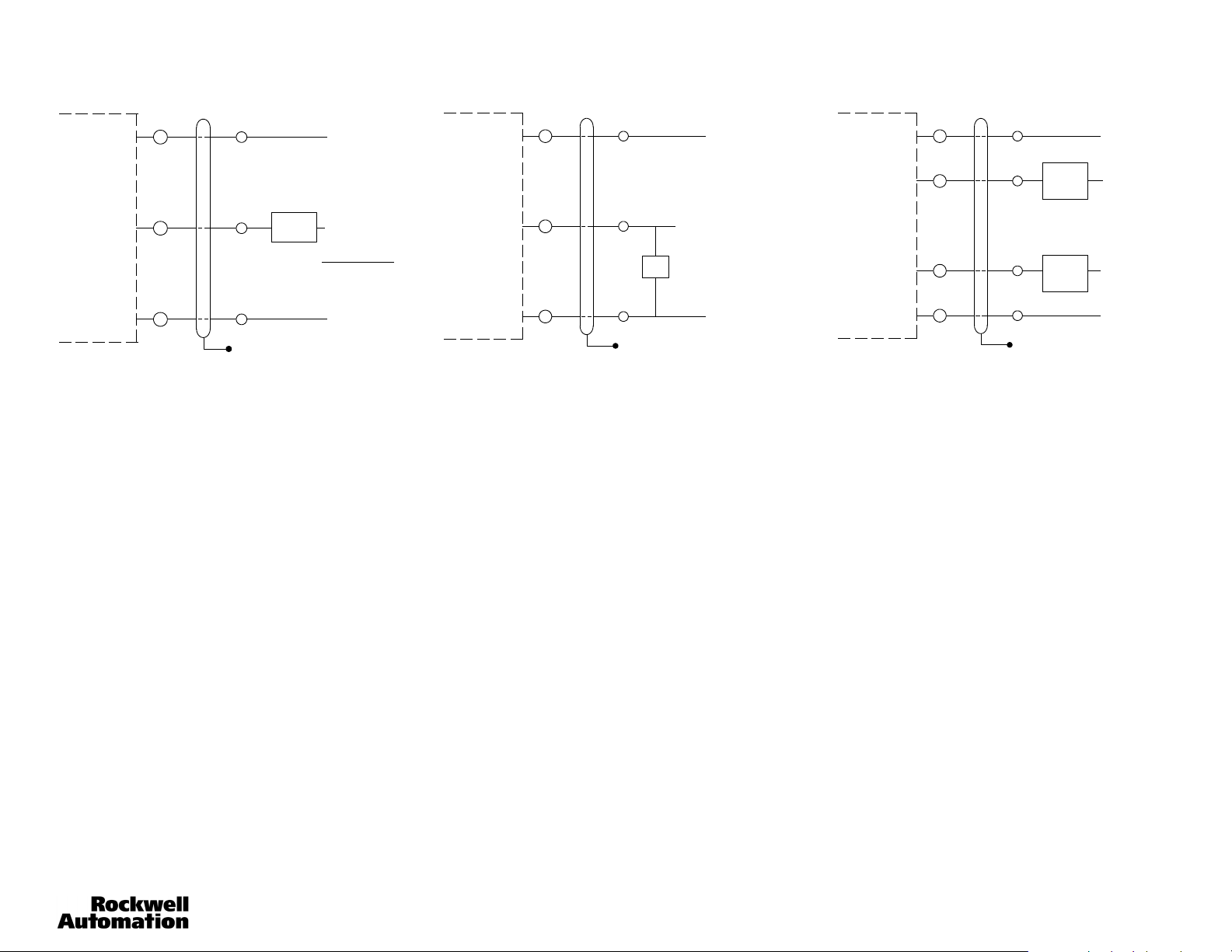
Wiring Diagrams
Analog Current Output Connections
Ter min al S tyl e
Power Base
+
2
--
Note: Details of connection of Allen-Bradley Series 5000 photoelectric sensors to Allen-Bradley Programmable Controllers can be found in
Publication 42MR-4.0.
Calibration of the Analog Output is done with a Voltmeter or an Ammeter. When calibrating the Voltage Output, connect
the Voltmeter between Terminal 2 (+) and the negative power supply Terminal 1 (--). Select the Voltmeter Scale for 10V
DC. When calibrating the Current Output, install the Ammeter between Terminal 2 (--) and the positive power supply
Terminal (+), or the positive of a separate power supply when used. Select the Ammeter scale for 20mA (DC).
1. With Selector Switches 1 and 2, select Analog Current or Voltage Output.
2. With Selector Switches 3 and 4, select Positive or Negative Slope operation.
3. Set retroreflective target at 0.61m (2ft). Adjust the Analog Output Calibration pot. for 10V DC or 20mA (2%) when in
Negative Slope operation, or to 1V DC or 1mA (10%) when in Positive Slope operation.
4. Set the retroreflective target at the desired range. 4.57m (15ft) maximum, 1.52m (5ft) minimum. Adjust the Sensing
Range Adjustment pot. for 1V DC or 1mA (10%) when using Negative Slope operation or to 10V DC or 20mA (2%)
when using Positive Slope operation.
5. Bring the retroreflective target back to 0.61m (2ft). Re-adjust the Analog Output Calibration pot. for 10V DC or 20mA
(2%) when using Negative Slope operation or to 1V DC or 1mA when using Positive Slope operation if necessary.
6. Place the retroreflective target at the desired range. Re-adjust the Sensing Range Adjustment pot. for 1V DC or 1mA
(10%) when using Negative Slope operation or to 10V DC or 20mA (2%) when using Positive Slope operation if
necessary.
The Analog Output is now calibrated.
Cable Style
Power Base
Red
Gray
Black
Floating Shield
(+) 22--28V DC
Current
Sensor
RMÁX = Supply Voltage -- 10V
(+) 40V DC Max
20mA
(-- )
Calibration of Setpoint Outputs
1. Place the retroreflective target at the distance where the Setpoint Output A is to come on.
2. Adjust the Setpoint pot. A to turn on Output A at this point. (Red LED turns on.)
3. Place the retroreflective target at the distance where the Setpoint Output B is to come on.
4. Adjust the Setpoint B to turn on Output B at this point. (Green LED turns on.)
Note: Be aware that in the retroreflective mode, when setting the range beyond 3.35m (11ft), white paper response may
occur between 2.54cm (1in) and 0.3m (1ft).
This completes the calibration of Setpoint Outputs.
Analog Voltage Output Connections
Terminal Style
Power Base
+
2
--
Cable Style
Power Base
Red
Gray
Black
Floating Shield
(+) 22--28V DC
Analog Output
Voltage Sensor
R = 3 k Ohm minimum
(-- )
NPN Set Point Output Connections
Ter mi na l Style
Power Base
+
3
1
--
Cable Style
Power Base
Red
Orang
e
Blue
Black
Floating Shield
100mA
100mA
Load
Max.
Load
Max.
(+) 22--28V DC
(+) 10--30V DC
(+) 10--30V DC
(--)
2
Page 3

Typical Response Curves—mm (inches)
R
Diff
etroreflectiveSensingMode
Voltage Output Slope
10
9
8
7
6
5
4
3
DC Voltage
2
1
0
03m
(1in)
Negativ
e Slope
09m
(3ft)
1.5m
(5ft)
15in x 15in
3M 7590
21m
27m
(7ft)
(9ft)
3.3m
(11ft)
Positive
Slope
3.9m
(13ft)
4.5m
(15ft)
DC Current (mA)
Current Output Slope
20
18
16
14
Negative
Slope
12
10
8
6
4
2
0
0.3m
0.9m
(1ft)
(3ft)
Operating DistanceOperating Distance
1.5m
(5ft)
15in x 15in
3M 7590
2.1m
2.7m
(7ft)
(9ft)
3.3m
(11ft)
Positive
Slope
3.9m
(13ft)
4.5m
(15ft)
Infrared Glass FO/Fixed Focus/Wide Angle Diffuse
10
9
8
7
6
5
4
3
DC Voltage
2
1
0
Curves shown represent output current/voltage when using sensor with 43GR--BAA72.L large aperture glass fiber optic cable to a 92--47 1.25in diameter reflector.
Voltage Output Current Output Voltage Output Current Output
300
(11.81)
Positive
Slope
400
(15.75)
Negative
100
(3.94)
Slope
200
(7.87)
20
18
16
14
12
10
Negative
8
Slope
6
4
DC Current (mA
2
0
100
200
(3.94)
(7.87)
300
(11.81)
Positive
Slope
400
(15.75)
Operating Distance—mm (in) Operating Distance—mm (in)Operating Distance—mm (in) Operating Distance—mm (in)
useSensingMode
10
9
8
7
6
5
4
3
DC Voltage
2
1
0
Voltage Output
Negative
Slope
0
0.3 m
(1ft)
Operating Distance
0.6 m
(2ft)
0.9 m
(3ft)
Positive
Slope
1.2 m
(4ft)
Visible Red FO/Fixed Focus/Wide Angle Diffuse
10
9
8
7
Negative
6
Slope
5
4
3
DC Voltage
2
1
0
100
(3.94)
(7.87)
200
300
(11.81)
Positive
Slope
(15.75)
400
Dimensions—mm (inches)
Terminal Style Power Base
To R em ove
Photohead
36.5
(1.437)
55.5
(2.186)
2.7.
(0.109)
8.7 Min.
(1.031)
71.0
(2.797)
65.8
(2.594)
0.953
(24.2)
33.3
(1.312)
0.469
(11.9)
106.5
(4.250)
(0.453)
Note: Hardware included with sensor: two (2) nickel plated 10--32 mounting screws.
15.4
139.5
(5.516)
Quick
Disconnect
Screw
LED
Indicator
1/2--14
NPSM
27.7
(1.093)
Top V ie w
(0.765)
Bottom View
10--32 UNF
2 Holes
19.4
13.8
(0.547)
38.3
(1.5)
8.3
(0.328)
36.5
(1.437)
Cable Style Power Base
0.609
55.5
(2.186)
(15.4)
73.0
(2.875)
1/4--18
NPSM
24.2
(0.953)
11.9
(0.468)
101.2
(3.984)
10ft (3m)
2.7
(0.109)
10--32 UNC
Cable
2 Holes
1/4--18
NPSM
(1.078)
27.3
1.5 m
(5ft)
DC Current (mA)
Bottom View
DC Current (mA)
19.0
(0.75)
20
18
16
14
12
10
8
6
4
2
0
20
18
16
14
12
10
8
6
4
2
0
8.3
(0.328)
Current Output
Negative
Slope
152
0
(6)
Operating Distance
Negative
Slope
100
(3.94)
38.3
(1.5)
55.5
(2.186)
0.6m
(2ft)
200
(7.87)
0.9m
(3ft)
300
(11.81)
1.2m
(4ft)
Positive
Positive
Slope
Slope
400
(15.75)
1.5m
(5ft)
3
Page 4

Accessories—mm (inches) (continued)
11.9
(0.47)
15.4
(0.61)
43.3
(1.70)
7.10
(0.28)
Control with Cable
67.3
38.1
(2.65)
(1.5)
6.3 (0.25)
Material
#11 GA CRS
24.2
(0.95)
101.6
50.8
(2)
67.5
(2.66)
(4.0)
73.0
(2.88)
Style Power Base
33.6 (1.33) Typ
76.2
(3.0)
9.6
(0.38)
38.1
(1.5)
3.17 (0.13)
8.73
(0.34)
138.1
(5.44)
8.26
(0.33)
120.6
(4.75)
73.4
(2.9)
1.75 Dia.
Clearance for
1
#
4-- 2 0 H D W
19
(0.75)
38.1
(1.5)
11.9
(0.47)
15.4
(0.61)
106.5
(4.25)
19
(0.75)
7.10
(0.28)
Control with Terminal
Style Power Base
43.6
(1.72) Dia.
0.09 RAD
33.6
(1.44)
Typ
14.6
(0.58)
38.1
(1.5)
12.7 (0.5)
12.7
(0.5)
14.6
(0.58)
36.1
(1.5)
24.2
(0.95)
50.8
(2)
67.5
(2.66)
(2.75)
69.8
8.73
(0.34)
136.9
(5.39)
42.9
(1.69)
38.1
(1.5)
178.6
(7.03)
8.26
(0.33)
3.0 (0.12)
69.8
(2.75)
Heavy Duty Mounting Assembly #60--1748General Purpose Mounting Assembly #60--1785
(0.95)
11.9
(0.47)
15.4
(0.61)
72.3
(2.84)
38.1
54.7
(1.5)
(2.16)
8.3
(0.33)
Control with Cable
Style Power Base
24.2
Clearance for
#10-32 HDW
38.1
(1.5)
6.3 (0.25)
61.9
(1.44)
8.73
(0.34)
46.4
(1.83)
25.4
(1)
Clearance for
#10-32 HDW
63.5
(2.5)
8.3
(0.33)
104.4
(4.11)
#10-32 Thread 2
63.5
(2.5)
24.2
(0.95)
11.9
(0.47)
15.4
(0.61)
Holes
31.7
(1.25)
6.3
(0.25)
38.1
(1.5)
6.3 (0.25)
61.9
(1.44)
Control with Terminal
Style Power Base
25.4
8.73
(0.34)
(1)
23.4
(0.92)
110. 3
(4.34)
54.7
(2.16)
146.4
(5.75)
63.5
(2.5)
Limit Switch Mounting Assembly #60--2230Flexi Mounting Assembly #60--2014
37
Full Rad.
44 (1.72) Dia.
(1.33)
34
102
(4.0)
(1.45)
67
(2.65)
4.5 (0.38)
19
(0.74)
(0.85)
(1.94)
30
(1.18)
6
(0.23)
21
82
49
(3.22)
Publication 75007--344--01(A)
August 2005
Printed in USA
4
 Loading...