

Page 1
Installation Instructions
Bulletin 42BT Long-Range Background Suppression
SAVE THESE INSTRUCTIONS FOR FUTURE USE.
Refer to the product catalog pages for additional information.
Description
The Allen-Bradley 42BT family of long-range background
suppression is designed for the reliable detection of objects
while ignoring background reflectivity.
These sensors also provide consistent detection of objec ts
regardless of color at a specifically taught distance.
Features
S Visible light source for ease of alignment (1 m models)
S Range indicator allows for an easy readout of the settings
S Adjustable range settings
S Two sensing ranges: 1 m (3.28 ft) and 2 m (6.56 ft)
S Highly visible LED indicators
S Both NPN and PNP Outputs
S Compact IP65 rated enclosure
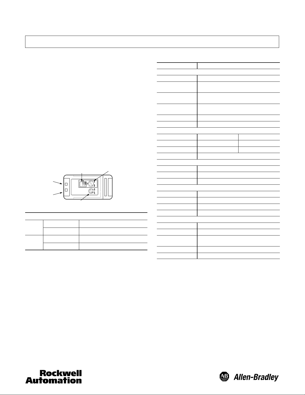
Sensor User Interface
Range Adjustment
Display
Margin
Indicator
Output
Indicator
LED Status
Green
Red
LED is ON when sensor is in light operate (L.O.) mode and a target is detected, LED is OFF
when the sensor is in dark operate (D.O.) mode and the target is detected.
OFF Low stability. Light intensity below 1.2X
ON High stability. Light intensity above 1.2X
OFF Output OFF
ON
Light/Dark
Operate Switch
Range Adjustment
Selector
Output ON
Specifications
Certifications cULus and CE marked for all applicable directives
Environmental
Operating Environment IP65
Operating
Temperature [C (F)]
Vibration 10…55Hz, 1.5 mm amplitude; meets or exceeds IEC
Shock 30 g with 1 ms pulse duration, meets or exceeds IEC
Relative Humidity 35…85%
Ambient Light Immunity Incandescent light: 3000 lux; sunlight: 10,000 lux
Optical
Models Sensing Range Light Source
42BT--B2LBSL--* 0.2…1 m (0.66…3.28 ft) Visible red (650 nm)
42BT--B1LBSL--* 0.2…2 m (0.66…6.56 ft) Infrared (880 nm)
Adjustments 5--turn sensitivity potentiometer
Electrical
Voltage 12…24V DC
Current Consumption 30 mA max
Sensor Protection Reverse polarity, short circuit
Outputs
Response Time 2msmax.
Output Type PNP or NPN
Output Mode Light and dark operate selectable
Output Current 100 mA max.
Mechanical
Housing Material Polyarilate
Lens Material Polyarilate
Connection Types 2 m cable, 4-pin DC micro (M12) pigtail, 4-pin DC pico
Supplied Accessories None
Optional Accessories Mounting brackets, cordsets
-- 2 5 …+55° (--13…131°)
60947--5--2
60947--5--2
(M8) pigtail
1
Page 2
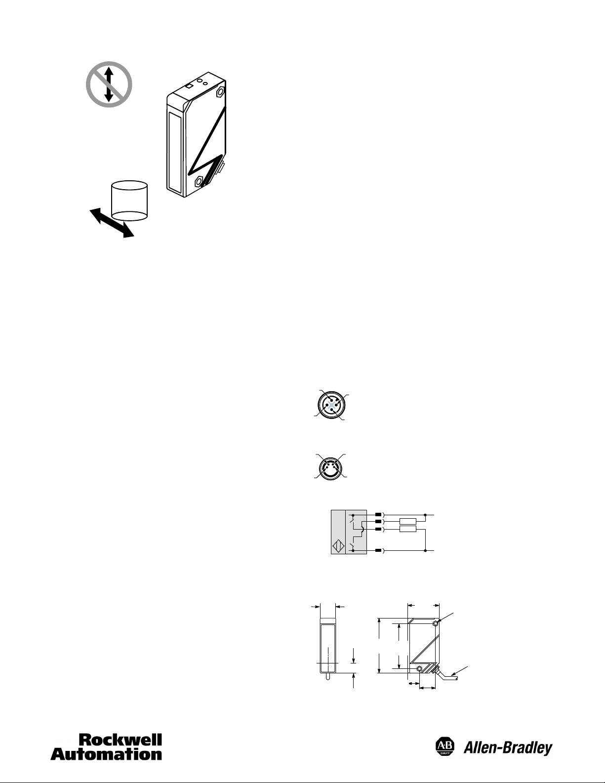
Background Suppression
Installation Considerations
Target
Note: Due to the detection method, targets traveling
horizontally to the sensor’s optics are detected. Targets
traveling vertically may not be accurately detected. For
reliable background suppression, a minimum
separation distance of 6 mm is recommended between
the target and the background.
Adjustment with no Background Present
1. Using an instrument screwdriver, adjust the suppression
point to its minimum setting by turning the knob
counterclockwise until a “click” can be heard.
2. The background suppression cutoff point for the 42BT
sensor may be set between 200 mm and a maximum of
2 m (depending on the model)
3. If no background is present up to the maximum rated
distance (1 m for 42BT--B2LBSL--F4 and 2 m for
42BT--B1LBSN--F4), the suppression point should be set
just after the target to be sensed. Do this by rotating the
knob clockwise with the target present until both indicators
(stability and output) turn ON
counterclockwise until both LEDs turn OFF
. Then rotate the knob
. When using
this method, ensure that the stability indicator (Green LED)
is ON.
4. The sensor is now configured to detect targets between
the sensor face and the suppression point. Note that the
reflectivity of the target and the background will influence
the detection capability of the sensor. Use the included
response curves to help characterize the
ٛ
sensor s
performance.
Selector switch in light operate (L.O.) mode. For dark operate (D.O.) mode, the stability LED
turns ON and output LED turns OFF.
Selector switch in light operate (L.O.) mode. For dark operate (D.O.) mode, the stability LED
turns OFF and output LED turns ON.
Mounting the Sensor
Securely mount the sensor on a firm, stable surface or
support. An application which is subject to excessive vibration
or shifting may cause intermittent operation. For installation
convenience, we offer a wide range of mounting brackets.
See the Accessories section for more details.
Sensor Adjustment
Once securely installed, the sensing range of the sensor must
be set using the five-turn adjustment knob on the top of the
sensor. This knob is used to set the suppression point (point
at which the background will be suppressed) of the sensor.
Adjustment with Background Present
1. Using an instrument screwdriver, adjust the suppression
point to its minimum setting by turning the knob
counterclockwise until a “click” can be heard.
2. The background suppression cutoff point for the 42BT
sensor may be set between 200 mm and a maximum of
2 m (depending on the model)
3. If a background is present up to the maximum rated
distance (1 m for 42BT--B2LBSL--F4 and 2 m for
42BT--B1LBSN--F4), the suppression point should be set
just before this background to allow detection of targets up
to that point. Do this by rotating the knob clockwise until
both indicators (stability and output) turn ON
the knob counterclockwise until both LEDs turn OFF
4. The sensor is now configured to detect targets between
the sensor face and the suppression point. Note that the
reflectivity of the target and the background will influence
the detection capability of the sensor. Use the included
response curves to help characterize the sensor’s
performance.
Selector switch in light operate (L.O.) mode. For dark operate (D.O.) mode, the stability LED
turns ON and output LED turns OFF.
Selector switch in light operate (L.O.) mode. For dark operate (D.O.) mode, the stability LED
turns OFF and output LED turns ON.
. Then rotate
.
Wiring Diagrams
Quick disconnect connection is shown in the following
diagrams. Pin numbers correspond to male connectors on the
sensor.
Micro (M12) Male QD on Pigtail
2
3
1
4
Pico (M8) Male QD on Pigtail
2
1
4
3
NPN and PNP Outputs
1
+
--
Quick-Disconnect
Brown
Black
4
White
2
3
Blue
+
--
Approximate Dimensions [mm (in.)]
57.5
(2.26)
40
(1.57)
2--4.2 (0.17)
20.5 (0.80)
Dia.
2 m cabl e
4.2 (0.17) Dia.
Axis
20
(0.78)
15 ( 0.59)
70
(2.75)
5.5 (0. 21)
2
Page 3

Accessories [mm (in.)]
Stainless Steel Stainless Steel
Vertical Mounting Bracket #61--6738 Horizontal Mounting Bracket #61--6739
5.2 (0.2)
20
20
(0.78)
42
(1.65)
2 ( 0.08)
(0.87)
Axis
6.4 (0.25)
19.5 (0. 76)
1.5
(0.06)
30 ( 1.18)
45 ( 1.77)
12 ( 0.47)
6.4 (0.25) Dia.
10_
22
(0.86)
20
(0.87)
6.4
(0.25)
Axis
12 ( 0.47)
42
(1.65)
22
(0.86)
22
(0.86)
19.5 (0. 76)
6
(0.23)
6.4 (0.25)
5 ( 0.19)
45 ( 1.77)
1.5
(0.06)
1.3
(0.05)
48
(1.89)
2 ( 0.08)
10_
Typical Response
42BT--B2LBSL 42BT--B2LBSN
Background Suppression (1 m) Background Suppression (2 m)
Detection Distance for a 150 x 150 mm Color Target Detection Distance for a 150 x 150 mm Color Target
(Matte surface) (Matte surface)
With detecting distance setting for white drawing paper at 1 m
1000
With detecting distance setting for white drawing paper at 2m
2
800
With detecting distance setting for white drawing paper at 500 mm
500
Distance (mm)
With detecting distance setting for white drawing paper at 200 mm
200
0
White
Yellow
Orange
Red
Green
Brown
850
1.58
480
With detecting distance setting for white drawing paper at 1 m
1
0.96
Distance (m)
Blue
Grey
Black
With detecting distance setting for white drawing paper at 200 mm
0.2
0
White
Yellow
Orange
Red
Brown
Green
Blue
Grey
Black
10000145378Ver 00
3
November 2010
 Loading...