

Page 1

ESRS – Encoder
Signal Reference
Simulator
(Cat. No. 4100-ESRS)
Installation and Setup Manual
Page 2

Important User Information
Because of the variety of uses for the products described in this
publication, those responsible for the application and use of this
control equipment must satisfy themselves that all necessary steps
have been taken to assure that each application and use meets all
performance and safety requirements, including any applicable laws,
regulations, codes and standards.
The illustrations, charts, sample programs and layout examples shown
in this guide are intended solely for purposes of example. Since there
are many variables and requirements associated with any particular
installation, Allen-Bradley does not assume responsibility or liability
(to include intellectual property liability) for actual use based upon
the examples shown in this publication.
Allen-Bradley publication SGI-1.1, Safety Guidelines for the
Application, Installation and Maintenance of Solid-State Control
(available from your local Allen-Bradley office), describes some
important differences between solid-state equipment and
electromechanical devices that should be taken into consideration
when applying products such as those described in this publication.
Reproduction of the contents of this copyrighted publication, in whole
or part, without written permission of Rockwell Automation, is
prohibited.
Throughout this manual we use notes to make you aware of safety
considerations:
ATTENTION
Identifies information about practices or
circumstances that can lead to personal injury or
death, property damage or economic loss
!
Attention statements help you to:
• identify a hazard
• avoid a hazard
• recognize the consequences
IMPORTANT
Allen-Bradley is a trademark of Rockwell Automation
Identifies information that is critical for successful
application and understanding of the product.
Page 3

European Communities (EC)
Directive Compliance
If this product has the CE mark it is approved for installation within
the European Union and EEA regions. It has been designed and
tested to meet the following directives.
EMC Directive
This product is tested to meet the Council Directive 89/336/EC
Electromagnetic Compatibility (EMC) by applying the following
standards, in whole or in part, documented in a technical
construction file:
• EN 50081-2 EMC — Generic Emission Standard, Part 2 —
Industrial Environment
• EN 50082-2 EMC — Generic Immunity Standard, Part 2 —
Industrial Environment
This product is intended for use in an industrial environment.
Low Voltage Directive
This product is tested to meet Council Directive 73/23/EEC Low
Voltage, by applying the safety requirement s of EN 61131-2
Programmable Controllers, Part 2 - Equipment Requirements and
Tests. For specific information required by EN 61131-2, see the
appropriate sections in this publication, as well as the Allen-Bradley
publication Industrial Automation Wiring and Grounding Guidelines
For Noise Immunity, publication 1770-4.1.
This equipment is classified as open equipment and must be
mounted in an enclosure during operation to provide safety
protection.
Page 4

Page 5

Table of Contents
Preface
Chapter 1
Using This Manual
Read This Manual . . . . . . . . . . . . . . . . . . . . . . . . . . . . . . . P-1
Who Should Use this Manual. . . . . . . . . . . . . . . . . . . . . . . P-1
Purpose of this Manual . . . . . . . . . . . . . . . . . . . . . . . . . . . P-1
Safety Precautions. . . . . . . . . . . . . . . . . . . . . . . . . . . . . . . P-2
Contents of this Manual . . . . . . . . . . . . . . . . . . . . . . . . P-3
Related Documentation . . . . . . . . . . . . . . . . . . . . . . . . P-3
Terminology. . . . . . . . . . . . . . . . . . . . . . . . . . . . . . . . . . . P-3
Common Techniques Used in this Manual . . . . . . . . . . . . . P-4
Product Receiving & Storage Responsibility . . . . . . . . . . . . P-4
Allen-Bradley Support. . . . . . . . . . . . . . . . . . . . . . . . . . . . P-5
Local Product Support . . . . . . . . . . . . . . . . . . . . . . . . . P-5
Technical Product Assistance . . . . . . . . . . . . . . . . . . . . P-5
On the Web . . . . . . . . . . . . . . . . . . . . . . . . . . . . . . . . . . . P-6
Overview
ESRS Description. . . . . . . . . . . . . . . . . . . . . . . . . . . . . . . . 1-1
Principal features of the ESRS. . . . . . . . . . . . . . . . . . . . 1-1
ESRS Front Panel. . . . . . . . . . . . . . . . . . . . . . . . . . . . . . . . 1-2
ESRS Footprint . . . . . . . . . . . . . . . . . . . . . . . . . . . . . . . . . 1-3
ESRS Principal Specifications . . . . . . . . . . . . . . . . . . . . . . . 1-4
Mechanical Specifications. . . . . . . . . . . . . . . . . . . . . . . 1-4
Environmental Specifications . . . . . . . . . . . . . . . . . . . . 1-4
Power Supply and Fuses . . . . . . . . . . . . . . . . . . . . . . . . . . 1-4
Power Supply Specifications. . . . . . . . . . . . . . . . . . . . . 1-4
Quadrature Output . . . . . . . . . . . . . . . . . . . . . . . . . . . 1-5
Index Pulse . . . . . . . . . . . . . . . . . . . . . . . . . . . . . . . . . 1-5
I/O Filtering . . . . . . . . . . . . . . . . . . . . . . . . . . . . . . . . 1-5
Chapter 2
i Publication 4100-IN505A-EN-P - October 2000
Installation
Mounting the ESRS . . . . . . . . . . . . . . . . . . . . . . . . . . . . . . 2-2
Enable Input. . . . . . . . . . . . . . . . . . . . . . . . . . . . . . . . . . . 2-2
External Power Supply . . . . . . . . . . . . . . . . . . . . . . . . . . . 2-6
Page 6

ii
Chapter 3
Operation
General . . . . . . . . . . . . . . . . . . . . . . . . . . . . . . . . . . . . . . 3-1
Indicators . . . . . . . . . . . . . . . . . . . . . . . . . . . . . . . . . . . . . 3-1
Controls . . . . . . . . . . . . . . . . . . . . . . . . . . . . . . . . . . . . . . 3-1
Line Speed . . . . . . . . . . . . . . . . . . . . . . . . . . . . . . . . . 3-1
When Set To Unidirectional. . . . . . . . . . . . . . . . . . . . 3-1
When Set To Bi-directional . . . . . . . . . . . . . . . . . . . . 3-2
Acceleration. . . . . . . . . . . . . . . . . . . . . . . . . . . . . . . . . 3-2
Rounding . . . . . . . . . . . . . . . . . . . . . . . . . . . . . . . . . . 3-2
Line Selection . . . . . . . . . . . . . . . . . . . . . . . . . . . . . . . 3-2
Inputs and Outputs. . . . . . . . . . . . . . . . . . . . . . . . . . . . . . 3-3
Line Speed Ref Out . . . . . . . . . . . . . . . . . . . . . . . . . . . 3-3
Strobe Out. . . . . . . . . . . . . . . . . . . . . . . . . . . . . . . . . . 3-3
Ext Line Speed In. . . . . . . . . . . . . . . . . . . . . . . . . . . . . 3-4
P1. . . . . . . . . . . . . . . . . . . . . . . . . . . . . . . . . . . . . . . . 3-4
Enable Voltage . . . . . . . . . . . . . . . . . . . . . . . . . . . . . 3-5
Enable Input. . . . . . . . . . . . . . . . . . . . . . . . . . . . . . . 3-5
Direction Output . . . . . . . . . . . . . . . . . . . . . . . . . . . 3-5
P2. . . . . . . . . . . . . . . . . . . . . . . . . . . . . . . . . . . . . . . . 3-6
Options Switch . . . . . . . . . . . . . . . . . . . . . . . . . . . . . . . . . 3-6
Setting the Option Switch. . . . . . . . . . . . . . . . . . . . . . . 3-7
Mode Selection. . . . . . . . . . . . . . . . . . . . . . . . . . . . . 3-7
Index Division Ratio Selection. . . . . . . . . . . . . . . . . . 3-8
Maximum Effective Motor Speed . . . . . . . . . . . . . . . . 3-8
Index
Publication 4100-IN505A-EN-P - October 2000
Page 7

Preface
Read This Manual
Who Should Use this
Manual
Read and understand this instruction manual. It provides the
necessary information to let you install, connect, and set up the
Encoder Signal Reference Simulator for safe, reliable operation. This
preface covers the following topics:
• Who should use this manual
• The purpose of this manual
• Terminology
• Common techniques used in this manual
• Allen-Bradley support
Y ou should read this manual if you are responsible for the installation
or set up of the Encoder Signal Reference Simulator.
If you do not have a basic understanding of the products listed below,
contact your local Allen-Bradley representative for information on
available training courses before using this product.
Purpose of this Manual
• S Class Compact motion controller
• 1394 GMC System module
This manual is an installation and set up guide for the Encoder Signal
Reference Simulator. It describes the procedures necessary to properly
install and configure it into your motion control system.
1 Publication 4100-IN505A-EN-P - October 2000
Page 8

Preface
P-2
Safety Precautions
The following general precautions apply to the Encoder Signal
Reference Simulator:
ATTENTION
!
Electric shock can kill. Make sure the Encoder Signal
Reference Simulator is safely installed in accordance
with the Installation and Set-up chapters of this
manual. Avoid contact with electrical wires and
cabling while power is on. Only trained service
personnel should open the electrical cabinet.
This product contains stored energy devices. To
avoid hazard of electrical shock, verify that all
voltage on the capacitors has been discharged before
attempting to service, repair, or remove this unit. Y ou
should only attempt the procedures in this manual if
you are qualified to do so and familiar with
solid-state control equipment and the safety
procedures in publication NFPA 70E and
BS-EN60204.
The system integrator is responsible for local safety
and electrical codes.
ATTENTION
!
An incorrectly applied or installed product can
result in component damage or a reduction in
product life. Wiring or application errors, such as
undersizing or inadequate DC supply, or excessive
ambient temperatures can result in a malfunction.
The Encoder Signal Reference Simulator contains
ESD (Electrostatic Discharge) sensitive parts and
assemblies. Static control precautions are required
when installing, testing, servicing, or repairing this
assembly. Component damage can result if ESD
control procedures are not followed. If you are not
familiar with static control procedures, refer to
Allen-Bradley publication 8000-4.5.2, Guarding
Against Electrostatic Damage or any other
applicable ESD Protection Handbook.
Publication 4100-IN505A-EN-P - October 2000
Page 9

Preface
Contents of this Manu al
Chapter Title Contents
Preface Describes the purpose, background, and scope
of this manual. Also specifies the audience for
whom this manual is intended.
1 Overview Provides a general description of the Encoder
Signal Reference Simulator, its features and
mechanical specifications.
2 Installation Provides the steps needed to successfully
mount and wire the Encoder Signal Reference
Simulator.
3 Operation Provides information on using the ESRS.
Related Documentation
The following documents contain additional information concerning
related Allen-Bradley products. To obtain a copy, contact your local
Allen-Bradley office or distributor.
P-3
For Read This Document Document Number
Instructions for installation and set-up for the 1394 GMC
system
Instructions for installation and set-up for the S Class
Compact motion controller
Instructions for using the Ultra Plus 1398 Ultra Plus User Manual 1398-5.1
An article on wire sizes and types for grounding electrical
equipment (North American standards)
An article on wire sizes and types for grounding electrical
equipment (European standards).
A complete listing of current Allen-Bradley documentation,
including ordering instructions. Also indicates whether the
documents are available on CD-ROM or in multi-languages
A glossary of industrial automation terms and abbreviations Allen-Bradley Industrial Automation Glossary AG-7.1
Terminology
In order t o avoid con fusion, we have us ed the foll owing gene ral terms
1394 Digital, AC, Multi-Axis Motion Control
System User Manual
IMC S Class Compact Motion Controller
Installation and Set-up Manual
National Electrical Code Published by the
BS-EN 60204 Electrical Equipment of
Machines
Allen-Bradley Publication Index SD499
1394-5.0
999-122
National Fire
Protection
Association of
Boston, MA.
Published by British
Standards Institute
in a specific manner within this manual. We define them as follows:
ESRS - Refers to the Encoder Signal Reference Simulator.
Publication 4100-IN505A-EN-P - October 2000
Page 10

Preface
P-4
For specific definitions of other terms used in industrial automation,
see the Allen-Bradley Industrial Automation Glossary (publication
number AG-7.1).
Common Techniques Used
in this Manual
The following conventions are used throughout this manual:
• Bulleted lists such as this one provide information, not
procedural steps.
• Numbered lists provide sequential steps or hierarchical
information.
• When we refer you to another location, the section name
appears in italics.
• The exclamation point inside of a triangle, followed by the word
“ATTENTION” indicate circumstances that can lead to personal
injury, death, property damage or economic loss. See example
below.
ATTENTION
Failure to observe these warnings may cause damage
to the unit, unexpected and/or uncontrolled
movement of peripheral equipment, and your health
and safety.
!
Product Receiving &
Storage Responsibility
Publication 4100-IN505A-EN-P - October 2000
• An important table indicates critical information. See the
following example.
IMPORTANT
You, the customer, are responsible for thoroughly inspecting the
equipment before accepting the shipment from the freight company.
Check the item(s) you receive against your purchase order. If any
items are obviously damaged, it is your responsibility to refuse
delivery until the freight agent has noted the damage on the freight
bill. Should you discover any concealed damage during unpacking,
you are responsible for notifying the freight agent. Leave t he shipping
container intact and request that the freight agent make a visual
inspection of the equipment.
Identifies information that is critical for successful
application and understanding of the product.
Page 11

Preface
Leave the product in its shipping container prior to installation. If y ou
are not going to use the equipment for a period of time, store it:
• in a clean, dry location
• within an ambient temperature range of 0 to 85° C (32 to 185° F)
• within a relative humidity range of 5% to 95%, non-condensing
• in an area where it cannot be exposed to a corrosive
atmosphere
• in a non-construction area
P-5
Allen-Bradley Support
Allen-Bradley offers support services worldwide, with over 75 Sales/
Support Offices, 512 authorized Distributors and 260 authorized
Systems Integrators located throughout the United States alone, plus
Allen-Bradley representatives in every major country in the world.
Local Product Support
Contact your local Allen-Bradley representative for:
• sales and order support
• product technical training
• warranty support
• support service agreements
Technical Product Assistance
If you need to contact Allen-Bradley for technical assistance, please
review the information in this manual first. Then call your local
Allen-Bra d l e y r e pr e s entative. F or the quickest possibl e r e sponse, we
recommend that you have the catalog numbers of your products
available when you call. See the Related Documentation section of
this chapter for the publication numbers of other manuals that can
help with this product.
Publication 4100-IN505A-EN-P - October 2000
Page 12

Preface
P-6
The Rockwell Automation Technical Support numbers are:
in Europe: (+44) 1270 580142
in North America (603) 443-5419
On the Web
For information about Allen-Bradley, visit the following World Wide
Web site:
http://www.ab.com/
Publication 4100-IN505A-EN-P - October 2000
Page 13

Overview
Chapter
1
ESRS Description
The Encoder Signal Reference Simulator (ESRS) generates a digital
speed reference for a motor and encoder feedback combination. In
practice the ESRS would be connected to the Master Encoder input of
a drive. The ESRS then generates quadrature pulses with selectable
index (i.e. marker) which a drive forces its motor/encoder to follow.
The ESRS operates in either unidirectional or bi-directional mode as
selected by the Options switch located on the printed circuit board
(PCB) of the ESRS. The rounding and acceleration functions are
operational in all modes and for all inputs including STOP.
Principal features of the ESRS
• Selectable Internal and External Line Reference inputs plus Stop.
• Separate Enable input, with status indication, allows for remote
control.
• Rate of acceleration and deceleration continuously variable
between 1.5 and 15 seconds.
• Five positions of rounding plus “OFF”.
• Powered with a single +5V or +12V DC input voltage taken from
either the drive’s Encoder connector or external power supply.
10
• User selectable Index pulse in the range 2
• Motor speed selectable in the range 1875 to 15000 RPM.
• Product housed in a rugged steel box with mounting tabs.
• Operates in Unidirectional and Bi-directional mode.
• Separate square wave “STROBE” output, which is synchronized
with the Index pulse, for triggering stroboscopes, oscilloscopes,
and so forth.
• Analog output indication of commanded speed.
1 Publication 4100-IN505A-EN-P - October 2000
, 211, 212, 213 counts.
Page 14

1-2
ON ENABLED
LINE SPEED
MIN MAX
ACCEL
MIN MAX
QUALITY
OFF MAX
ROUNDING
SELECTION
INT
STOP
EXT
LINE
SPEED
REF
OUT
STROBE
OUT
EXT
LINE
SPEED
IN
P1
P2
4100 - ESRS
Overview
• Digital output indicates phase of quadrature pulse train (i.e.
direction of motor rotation).
ESRS Front Panel
The following illustration shows the placement and labelling of major
items on the ESRS front panel.
Figure 1.1 ESRS Front Panel Layout
Publication 4100-IN505A-EN-P - October 2000
Page 15
Overview
1-3
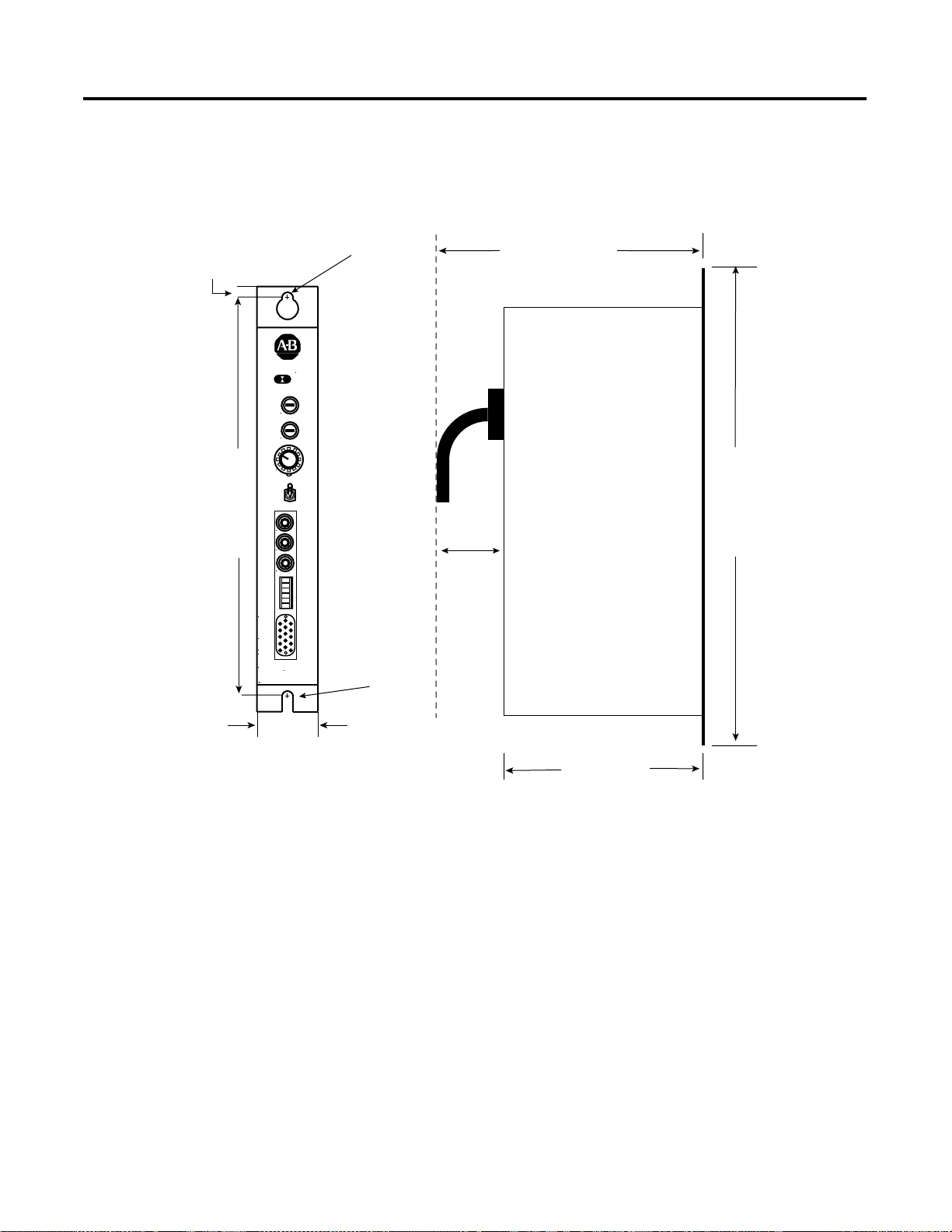
ESRS Footprint
7.62 mm (0.3 in)
7.92 mm (0.312 in) DIA.
QUALITY
ON ENABLED
LINE SPEED
MIN MAX
ACCEL
MIN MAX
ROUNDING
OFF MAX
SELECTION
INT
STOP
EXT
LINE
SPEED
REF
OUT
STROBE
323.85 mm (12.75 in)
OUT
EXT
LINE
SPEED
IN
P1
The following figure shows the footprint of the ESRS with fixing hole
dimensions and drilling details.
Figure 1.2 ESRS Dimensions
254 mm (10 in.) with
cable clearance
342.9 mm (13.5 in)
101.6 mm (4 in)
4100 - ESRS
P2
7.92 mm (0.312 in) DIA.
43.18 mm (1.7 in)
152.4 mm (6 in)
Publication 4100-IN505A-EN-P - October 2000
Page 16

1-4
Overview
ESRS Principal
Specifications
Mechanical Specifica tio ns
Table 1.A Mechanical S pecifications
Enclosure Type Steel case with integral mounting feet on rear edge.
Enclosure Size English (inch)
11.6 x 13.5 x 1.7
Metric (mm)
295 x 343 x 43
Environmental Speci fica tio ns
Table 1.B Envi r onmental Spec if ications
Operating Storage
Temperature
Humidity
o
0 to 60
C -40 to 70oC
95% non condensing @ 60
o
C
Power Supply and Fuses
Power Supply Specifications
Table 1.C Power Specifications
Input Voltage +5 or +12V DC. Both ± 5%
Current Draw Approximately 0.6A DC
Overcurrent Protection Overcurrent protection is provided by
separate +5V (F102) and +12V (F103) PCB
mounted fuses rated at T1.6A. A spare
fuse (F101) is also provided on the PCB.
If +5V and +12V are applied
simultaneously, the ESRS selects
the +12V input.
The ESRS is intended to take its
power from the encoder supply of
the target equipment. However, the
user should establish that this
supply has sufficient capacity to
provide the current indicated above.
If necessary, an additional power
supply is required – see
Installation
.
Chapter 2:
Publication 4100-IN505A-EN-P - October 2000
Page 17

Overview
Quadrature Output
Table 1.D Quadrature Outpu t
Number of quadrature outputs provided. One
Output format Incremental quadrature with Index pulse.
Output data type RS422 TTL Levels.
Quadrature output frequency 0 to 275kHz.
Quadrature output phase Forward is defined as A phase leading B.
Reverse is defined as B phase leading A.
Index Pulse
Table 1.E Index Pulse
1-5
Index division ratios.
Index pulse type Gated
Selectable in the range : 2
pulses.
The index pulse is high (Logic 1 or
True) only when the selected
division ratio has been satisfied and
the A and B phases are High.
10
, 211, 212, 213
I/O Filtering
Table 1.F I/O Filtering
High Frequency Filtering. High Frequency filtering is provided on all
power, digital and analog I/O lines as
appropriate.
Over-Voltage Clamping Over-voltage clamping is provided on the
power supply inputs, the quadrature and
index outputs, and the “EXT LINE SPEED
IN” input.
Publication 4100-IN505A-EN-P - October 2000
Page 18

1-6
Overview
Publication 4100-IN505A-EN-P - October 2000
Page 19

Chapter
2
Installation
The ESRS is designed to be mounted in an electrical cabinet via the
mounting tabs on its back panel. For all applications, this installation
method should be observed. Before powering up your ESRS, make
sure it has been configured correctly and that all peripheral
equipment has been correctly connected to it.
ATTENTION
!
The following safety points must be observed when installing the unit:
• The 5V or 12V DC supply must be electrically isolated from all
other supplies with higher potentials.
• The 0V (common) side of the 24V DC supply must be connected
to a safety ground.
• The unit is intended for installation and use within an electrical
control cabinet in a normal industrial environment.
Do not apply power to your ESRS when it is part of a
control system without first establishing that this will
not have any adverse effects.
Do not make or break any electrical connections to
your ESRS while power is applied.
Do not change any option switch settings on your
ESRS while power is applied.
Failure to observe the above warnings may cause
immediate and uncontrolled movement of controlled
hardware, damage to the ESRS, peripheral
equipment, and your health and safety.
• When used in an electrical cabinet, the case of the ESRS must be
bonded to the cabinet via the mounting feet.
1 Publication 4100-IN505A-EN-P - October 2000
Page 20

2-2
Installation
Mounting the ESRS
The ESRS must be properly grounded to the metal enclosure panel.
The following diagram shows how to ground the ESRS to the panel.
Figure 2.1 Mounting and Grounding Diagram
#10 AWG to
Ground Bus
ESRS Mounting Tab
Ground
Lug
Internal Star Washers
Size 1/4 - 20 or M6
Hardware
Enable Input
Tapped Hole
(Minimum of 3 Threads)
Scrape paint off panel to insure
electrical connection between
chassis and grounded metal plate.
Metal Panel
(Must be connected to
earth ground.)
There are several ways in which the Enable Input can be wired. The
diagrams on the following pages indicate the various connection
options.
The following diagram shows how to connect the ESRS to continually
enable the device from the internal Enable supply.
Publication 4100-IN505A-EN-P - October 2000
Page 21

Figure 2.2 ESRS Continually Enabled – Power Supplied by the ES RS
Link Pins 1 & 3
and 2 & 4
1
2
Installation
2-3
3
4
5
6
P1
P2
Publication 4100-IN505A-EN-P - October 2000
Page 22

2-4
Installation
The next diagram shows how to connect the ESRS to enable the
device from a source provided by the users equipment.
Figure 2.3 ESRS Enabled – Power Supplied by Users Equipment
5V to 24V DC
Supplied by User
1
2
3
P1
4
5
6
P2
Publication 4100-IN505A-EN-P - October 2000
Page 23

Installation
2-5
This figure shows how to connect the ESRS to enable the device from
its internal Enable supply and control with volt free contacts.
Figure 2.4 ESRS Enabled via Volt Free Contacts – Power Supplied by ESRS
Users Volt Free
Contacts
1
2
3
P1
4
5
6
P2
Publication 4100-IN505A-EN-P - October 2000
Page 24

2-6
Installation
This diagram shows how to connect the ESRS to enable the device
from a source provided by your equipment and control the Enable
with volt free contacts.
Figure 2.5 ESRS Enabled via Volt Free Contacts – Power Supplied by Users
Equipment
Users Volt Free
Contacts
1
2
External Power Supply
3
P1
5V to 24V DC
Supplied by User
4
5
6
P2
The following diagrams indicate how an external power supply
should be connected to the ESRS in cases where the encoder supply
in the target equipment has insufficient capacity to drive it. The
Publication 4100-IN505A-EN-P - October 2000
Page 25

Installation
recommended minimum current capacity for the external power
supply is 1 Amp.
2-7
ATTENTION
The ESRS does not contain reverse supply polarity
protection. You must observe polarity when
installing the unit. Reverse supply polarity can
permanently damage the ESRS.
!
This diagram shows how to connect the ESRS to a power supply
adjacent to the ESRS.
Figure 2.6 External Power Supply Adjacent to Encoder
Link PINS
9 and 14
+
_
External
5V DC Supply
PIN 9
P2
PIN 6
Publication 4100-IN505A-EN-P - October 2000
Page 26

2-8
Installation
Link Pins
9 and 14
The next diagram shows the ESRS connected to a power supply
adjacent to the drive or controller.
Figure 2.7 External Power Supply Adjacent to Drive/Controller
User's Drive
or Controller
P2
Pin 9
Pin 6
+
_
External
5V DC Supply
Publication 4100-IN505A-EN-P - October 2000
Page 27

Operation
Chapter
3
General
Indicators
Controls
Your ESRS is fitted with a range of indicators and controls to allow
easy configuration and use. This chapter explains the function and
operation of these and provides additional technical data where
appropriate.
There are two green LED indicators provided on the ESRS front panel:
OK and Enable.
The OK indicator relates the status of the applied power (either +5V
DC or +12V DC) and associated fuse. When the LED is lit, it indicates
that power is applied and the fuse is healthy.
The Enable indicator relates the status of the Enable input. When it is
lit, the Enable input is active and the ESRS is enabled.
The ESRS provides controls for Line Speed, Acceleration, Rounding,
and Line Selection.
Line Spee d
The Line Speed control of the ESRS allows the user to set the desired
line speed from the ESRS. The control is a 270 degree potentiometer
accessible from the front panel of the ESRS. For tamper avoidance, the
control is screwdriver operated. The function of this control is
dependent on whether the Option Switch is set to Unidirectional or
Bi-directional.
When Set To Unidirectional
When Unidirectional Mode is selected, zero speed occurs in the MIN
position and maximum speed occurs in the MAX position. The
direction of rotation in this mode is set by the Options switch.
1 Publication 4100-IN505A-EN-P - October 2000
Page 28

3-2
Operation
When Set To Bi-directional
When Bi-directional Mode is selected, zero speed occurs at the center
of rotation. Maximum reverse speed occurs in the MIN position and
maximum forward speed occurs in the MAX position.
Acceleration
The Acceleration control allows the user to set the rate of motor
acceleration. It is a 270 degree potentiometer accessible from the front
panel of the ESRS. For tamper avoidance, it is screwdriver operated.
Minimum acceleration occurs in the MIN position and maximum
acceleration occurs in the MAX position. The acceleration is
continuously variable between these limits.
When the rounding switch in the OFF position, the motor accelerates/
decelerates linearly at the rate set by the ACCEL control. For any
particular setting, the acceleration and deceleration rates are equal.
Rounding
The Rounding control lets you round off the acceleration at the start
and end points. The Rounding control is a 6 position rotary switch
with a knob mounted on the front panel of the ESRS.
No rounding is applied in the OFF position. Minimum rounding
occurs at the next CW position and the maximum rounding is applied
in the MAX position. Within the selected range, the amount of
rounding applied is proportional to the rate of acceleration.
Line Selection
This 3 position toggle switch lets you select whether to use an internal
line, an external line or stop.
INT – Positioning the togg le switch at INT selects the line speed
control mounted in the ESRS.
STOP – Toggling to the STOP position removes all line references and
forces the motor to stop when the acceleration and rounding settings
allow. The STOP position overrides the Enable input and stops the
motor even when the Enable input is active.
Publication 4100-IN505A-EN-P - October 2000
Page 29

Operation
EXT – This setting selects a customer supplied line speed input via the
EXT LINE SPEED IN input.
3-3
Inputs and Outputs
The following analog and digital inputs and outputs are provided.
Line Spee d Ref Out
The ESRS provides an analog indication of commanded speed after
rounding and acceleration have been applied. The analog output
range is 0V > Vout > 10V.
The output produces a voltage ranging from 0 to +10 V DC as the
commanded speed varies from stationary to the selected maximum.
Within the speed range selected, the output voltage is directly
proportional to speed.
In Bi-directional Mode, this output produces +10V DC at maximum
speed for both directions of rotation. The direction of rotation is then
defined by the quadrature pulse phase via the Phase Output.
The impedance of this output is approximately 300Ω. Therefore to
ensure low interface errors, any device connected to this output
should have an input resistance of greater than 30kΩ.
Strobe Out
The Strobe Out is a TTL Digital Output providing a buffered signal to
trigger stroboscopes, oscilloscopes, and so forth.
This output provides a TTL square wave whose rising edge is
synchronized to the rising edge of the Index pulse.
Publication 4100-IN505A-EN-P - October 2000
Page 30

3-4
Operation
The Strobe Out is a square wave. Its falling edge is centered between
the consecutive rising edges of the Index Pulse.
Figure 3.1 ESRS Strobe and Index Pulses
INDEX
STROBE
Ext Line Speed In
This is an analog input requiring a DC voltage within the range of
-10V > Vin > +10V. You can set the commanded speed from an analog
voltage wi t h in th i s ran g e . Wi th i n the selected range, the m o t o r sp e e d
is directly proportional to input voltage.
In Unidirectional mode, zero speed occurs at 0V input voltage and
maximum speed occurs at +10V DC input voltage. The direction of
rotation in this mode is set by the Options switch.
In Bi-directional mode, zero speed occurs at 0V DC input voltage.
Maximum reverse speed occurs at -10V DC input voltage and
maximum forward speed occurs at +10V DC input voltage.
When the ESRS is set to EXT, the LINE SPEED control has no function.
The input resistance of this input is 100kΩ. Therefore the output
resistance of the device driving this input should be 1kΩ or less to
avoid interface errors.
Input clamping at ±15V is provided at this input. The input current is
not limited by the ESRS when clamping occurs.
Acceleration and rounding are operational in this mode.
P1
Publication 4100-IN505A-EN-P - October 2000
The P1 connector is a 2 part 6 way mating screw that lets you make
the connection to the Enable Voltage Input and Output and the
Direction Output.
Page 31

Operation
3-5
The following table shows the Pin number and its signal name.
Table 3.A P1 Pin Functions
Pin Number Signal Name
1 Enable Voltage, +15V
2 Enable Voltage, 0V
3 Enable Input
4 Enable Input
5 Direction Input
6 Direction Output, 0V
Enable Voltage
This provides a current limited supply to power the Enable input.
Enable Input
This input, which is opto-isolated, allows control of the ESRS via an
applied voltage in the range of 5 to 24V DC. The Enable voltage can
be applied with either polarity (AC voltages cannot be used). Voltage
must be applied to the Enable Input to make the chosen line
reference available. Removing the Enable voltage has the same effect
as selecting STOP on the SELECTION switch.
In situations where it is required to control the ESRS via volt free
contacts, the Enable voltage provided can be routed through these to
the Enable Input.
In cases where you supply the Enable voltage, the current required to
drive this input can be determined by calculating:
I
ENABLE
= (V
ENABLE
- 1.5) / 4700
Direction Output
This digital output indicates the phase of the quadrature pulse train.
The switched element is a relay with contact rating of 24V DC at 0.5 A.
The following table defines the functionality of the Direction Output.
Table 3.B Output Direction Values
Direction Output Quad. Pulse Phase
ON A leads B
OFF B leads A
Publication 4100-IN505A-EN-P - October 2000
Page 32

3-6
Operation
P2
The P2 connector is a 15 way male high density D connector. I t allows
you to make connection to the quadrature pulse train and index plus
power (+5 and +12V DC).
The following table shows the Pin Number and the matching Signal
name.
T able 3.C P2 Pin Functions
Pin Number Signal Name
1A+
2A3B+
4B5 I+ (Z+)
6Common
7Common
8 +12V DC
9 +5V DC
10 I- (Z-)
11 Not Used
12 Not Used
13 Not Used
14 +5V DC
15 Shield
Options Switch
Publication 4100-IN505A-EN-P - October 2000
The A+ and A-, B+ and B-, I+ and I- outputs are RS422 TTL level
outputs. These outputs are intended to be connected to bi-directional
line receivers in the target equipment. If single ended outputs are
required A+, B+, and I+ outputs can be used and A-, B-, and I- are left
unconnected.
The Options Switch is a 10 lever DIP switch mounted on the printed
circuit board (PCB). Use this switch to set the various configurations
options. With the box mounted vertically, the switch is positioned on
the horizontal. Each of the 10 levers is numbered from left to right
with 1 being to the extreme left and 10 being to the extreme right. A
switch is in the ON position when the upper portion of the lever is
depressed. It is in the OFF position when the lower portion of the
lever is depressed.
Page 33

Operation
3-7
Setting the Option Switch
Y ou must remove the side panel of the ESRS box to gain access to the
DIP switches.
ATTENTION
Removal of the side panel and setting of DIP
switches should be performed by authorized
personnel only. Proper safety precautions must be
followed to reduce the risk of damage to the unit,
other equipment, and health of personnel.
!
Set the DIP switches by pressing the appropriate lever to either its ON
or OFF position based on the following switch setting values.
When configuring the ESRS with the DIP switches, some of the
settings are cumulative. These setting combinations determine the
actual configuration. Make sure all of the levers are in the correct
position for the desired configuration.
Mode Selection
DIP switch levers 1 and 2 determine the operating mode of the ESRS.
Switch 1 – ON = Unidirectional; OFF = Bi-directional.
Switch 2 – ON = Unidirectional Mode - Forward;
OFF = Unidirectional Mode - Reverse.
TIP
When Switch 1 is in the OFF position, for
Bi-directional Mode, Switch 2 has no effect.
Publication 4100-IN505A-EN-P - October 2000
Page 34

3-8
Operation
Index Division Ratio Selection
Switch 3 and Switch 4 are used to create 4 patterns based on their
ON/OFF combinations. The patterns determine the pulse ranges, the
pulses per revolution, and the counts per revolution.
Ta ble 3.D Index Division Ratio Selection
Switch Settings for
Switch 3/ Switch 4
OFF/OFF
ON/OFF
OFF/ON
ON/ON
Pulse
Range
Pulses Per
Revolution
10
2
11
2
12
2
13
2
1024 4096
2048 8192
4096 16384
8192 32768
Counts per
Revolution
Maximum Effective Motor Speed
The Maxim um E f fe c t i v e M o t o r Speed is dep endent on the c o m bi n e d
values for Switch 3 and Switch 4. Only one of the switches numbered
5 through 10 should be in the ON position. The default setting has
Switch 5 in the ON position with switches 6 through 10 in their OFF
positions.
TIP
Having more than one switch, in series 5 through 10,
set to the ON position results in an undefined
maximum RPM speed. No switches, in series 5
through 10, set to the ON position results in an
output speed of zero. In either case, no damage is
done to the ESRS.
Table 3.E Maximum Effective Motor Speed (RPM) Selection
Switch
Number
5 1500 750 375 187
6 3000 1500 750 375
7 6000 3000 1500 750
8 9000 4500 2250 1125
9 12000 6000 3000 1500
10 15000 7500 3750 1875
Publication 4100-IN505A-EN-P - October 2000
Switch 3 and 4 set
to: OFF/OFF
Switch 3 and 4 set
to: ON/OFF
Switch 3 and 4 set
to: OFF/ON
Switch 3 and 4 set
to: ON/ON
Page 35

Index
A
Allen-Bradley Support
P-5
C
3-2
3-1
3-2
P-4
2-6
P-3
3-2
3-1
2-7
Common Techniques
Connecting
external power supply
External Power Supply Adjacent to Drive/ Controller
External Power Supply Adjacent to Encoder
Contents of this Manual
3-1
2-3
Continually
Controls
Acceleration
Line Selection
Line Speed
When Set To Bi-directional
When Set To Unidirectional
Rounding
3-2
E
Enable Input
Enabled Output
Continually En abled
ESRS Enabled
ESRS Enabled via Vol t Free Contacts
ESRS Enabled vi a Volt Free Contact s – Power Su pplied by
ESRS Description
ESRS Dimensions
ESRS Front Panel Layout
External Power Supply
2-2
2-3
2-4
Users Equipment
1-1
1-3
1-2
2-6
2-6
2-5
2-8
wiring
Enable Input
L
LED
Enable indica to r
OK indicator
LED indicators
3-1
3-1
3-1
O
Operation
Options Switch
3-1
3-6
Setting
3-7
Index Division Ratio
Maximum Effective Motor Speed
Mode Selection
P
P1
3-4
Direction Output
Enable Input
Enable Voltage
P1 connector
P2 connector
Principal features
Product Receiving
Purpose of this Manual
3-4
3-6
3-5
3-5
1-1
3-5
P-4
R
Read This Manual
Related Documentation
P-1
2-2
P-1
P-3
3-8
3-8
3-7
F
Front Panel
1-2
I
Inputs and Outputs
Ext Line Speed In
Line Speed Ref Out
P1
3-4
P2
3-6
Strobe Out
Installation
Mounting and Grounding
safety points
3-3
Strobe and Index Pulses
2-1
2-1
3-3
3-4
3-3
2-2
3-4
S
1-4
1-5
1-5
1-4
1-4
1-4
P-5
P-5
P-2
Safety Precautions
Specifications
Environmental
I/O Filtering
Index Pulse
Mechanical
Power Supply
Quadrature Output
Storage Responsibility
Support
Allen-Bradley,
local product,
1-5
P-4
Publication 4100-IN505A-EN-P - October 2000
Page 36

I-2
Index
technical product assistance,
support
On the Web
P-6
T
Terminology
P-3
P-5
W
Who Should Use this Manual
World Wide Web site
P-6
P-1
Publication 4100-IN505A-EN-P - October 2000
Page 37

Back Cover
Publication 4100-IN505A-EN-P - October 2000 1 PN 4100-IN505A
Supersedes Publication 4100-5.5 - November 1998 © 2000 Rockwell International Corporation. Printed in the U.S.A.
 Loading...