

Page 1
INSTALLATION INSTRUCTIONS
PHOTOSWITCH
MINIATURE END VIEW
TRANSMITTED BEAM CONTROL, BULLETIN 40BY1/47BU1- 4000
IMPORTANT: SAVE THESE INSTRUCTIONS FOR FUTURE USE. FOR ADDITIONAL INFORMATION REFER TO PUBLICATION PG-9000
BULLETIN NUMBER TYPE RESPONSE TIME
40BY1--4000
+
47BU1--4000
Light Source
Receiver
Refer to
22 Series 4000
or
40BY1--4000
+
Diffuse 6 (.15m) 12 (.3m)
22 Series 5000
47BU1--4000
+
63--70
SPECIFICATIONS
Field of View 7.5......................................
Transmitting LED Infrared, 940nm........................
Ambient Temperature Range -- 4 0 Fto185F(--40Cto85C)..
Approvals UL Listed and CSA Certified....................
Operating Environment NEMA 3, 4, 12, 13 and IP66 (IEC529)..
Housing High impact chemically resistant Housing............
Cable
Light Source 2 conductor vinyl jacketed cable 10 (3m).......
Receiver 2 conductor vinyl jacketed cable 10 (3m)..........
OPERATING DISTANCE SELECTION
The maximum operating distance is based on installing the control
in a relatively clean environment. Normalindustrial environment actually ranges from moderately dustyto extremelydirty. Greater oper-
ating margin (excess gain) mayberequired,whichcan be obtained by
reducing the operating distance of the control. (optics should be
cleaned regularly.)
OPERATING DISTANCE
22DJ3--4000 22DJ4--4000
22DJ9--4000
22DJ4--5000
22DJ9--5000
22DJ9--4001
2 (.61m) 5 (1.52m) 3 (.90m)
With 63--70 Range Extender
10 (3.05m) 25 (7.62m)
INSTALLATION
The control must be securely mounted ona firm, stable surface or
support. A mounting which is subject to excessive vibration or shifting may cause intermittent operation.
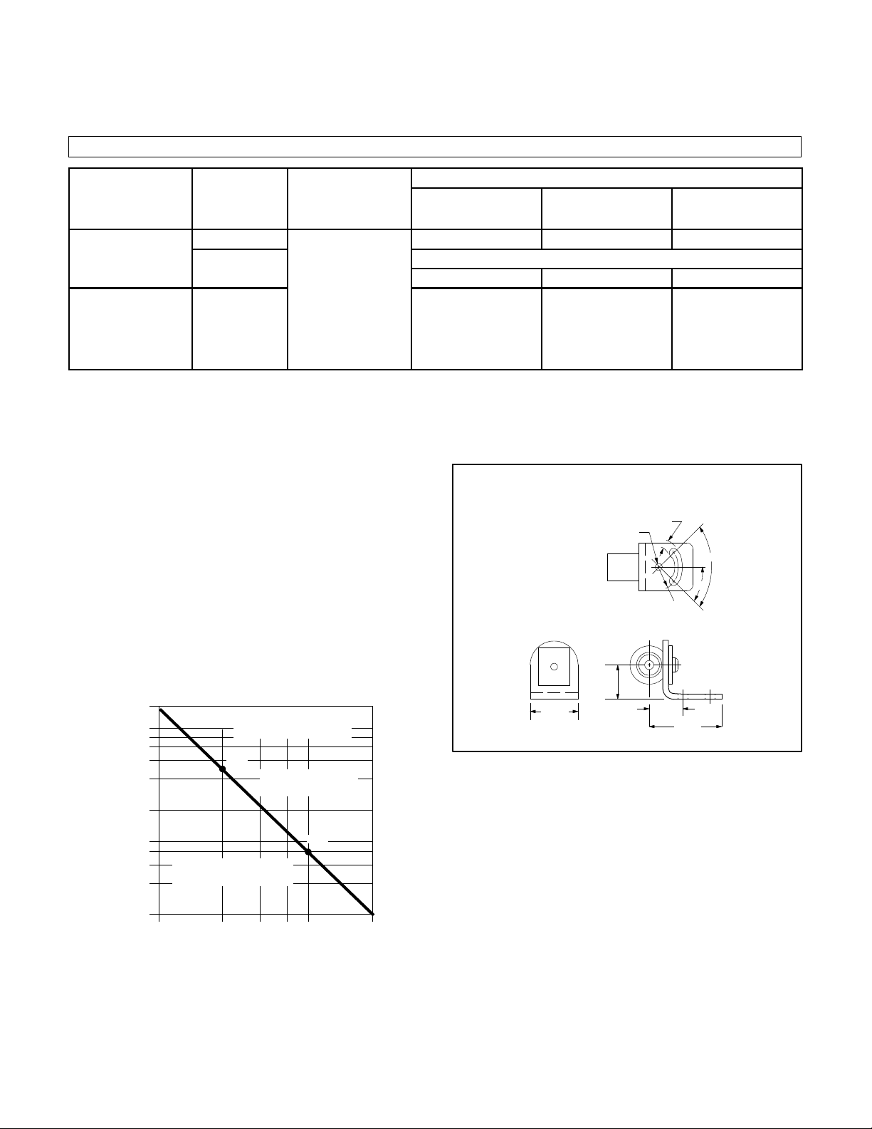
UNIVERSAL MOUNTING ASSEMBLY #61--4847
.196 (5)
13/64 (5.16)
DIA. HOLE
SLOT
1/2R
(12.7)
0
90
0
45
TYPICAL RESPONSE CURVE
100X
50x
40x
30x
20x
10x
5x
4x
Recommended Operating Range
3x
OPERATING MARGIN
Derating For “normal” Industrial
Environments
2x
1x
10% 20% 30% 40% 50% 100%
Percent of Maxium Operating Range
T
Transmitted Beam Operating
Range Selection
2
Recommended Operating
Range Derating For “dirty”
Industrial Environments
23/32
(18.3)
11/8
T
1
23/32
(18.3)
17/32
(38.9)
Page 2
WIRING
All external wiringshould conform to TheNational Electric Code
and applicable local codes. See wiring diagrams for external connections. For maximumelectric shielding, rigid conduit isrecommended
for extensions of scanner wiring. DO NOT RUN PHOTODETECTOR WIRES AND LINE VOLTAGES IN THE SAME CONDUIT.
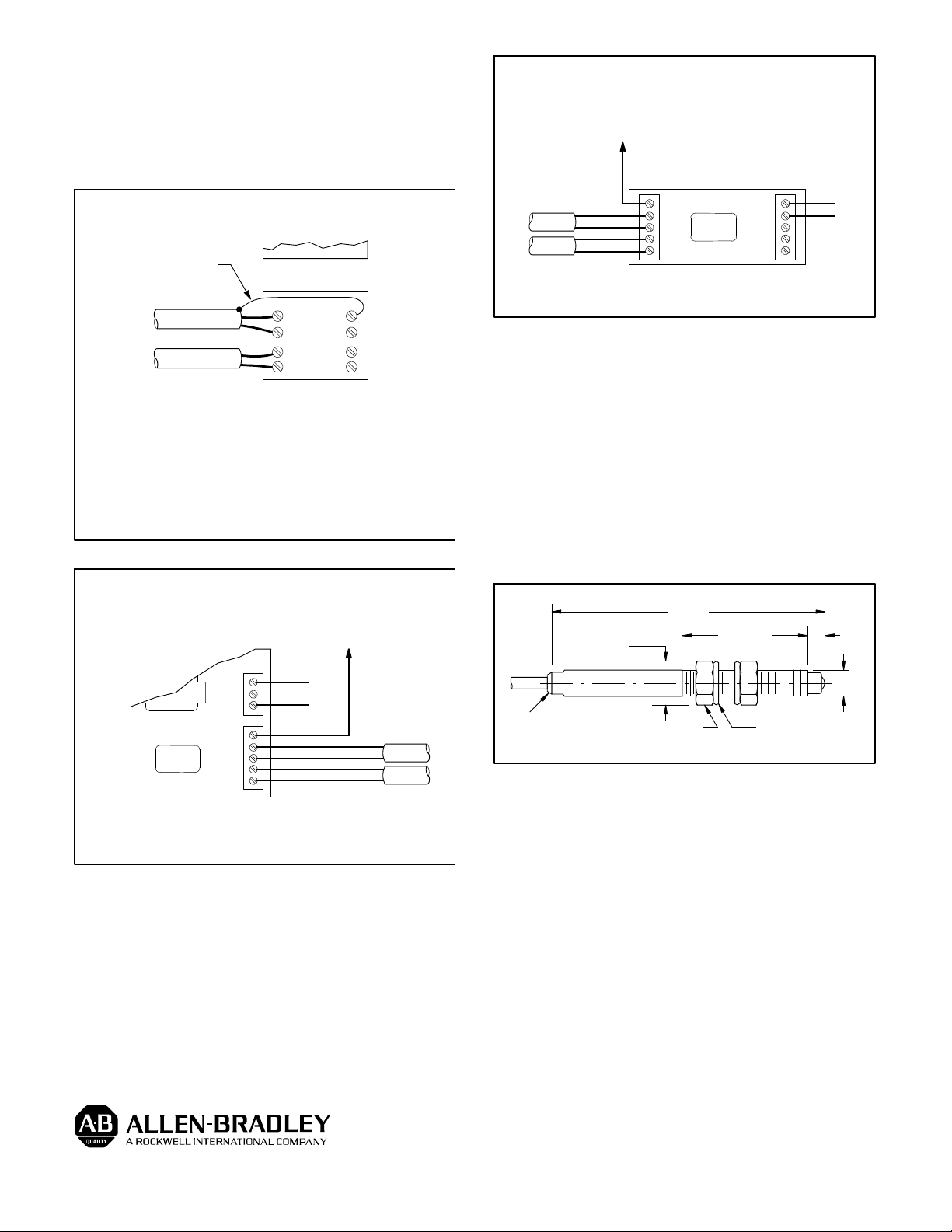
WIRING DIAGRAMS
47BU1--4000 AND 40BY1--4000
SHIELD WIRE SHOULD
BE INSULATED BY USER
47BU1 RECEIVER
40BY1 LED SOURCE
BLK
RED
RED
WHT
CONTROL BASE ONLY
Notes:
1. Receiver housing must always be grounded.
2. Do not ground light source shield or terminal 4.
3. Receiver housing is connected internally to its cable
shield, so shield will be automatically grounded.
4. Light source housing is not connected internally to its
cable shield. It may be grounded, but is not required.
PLUG-IN
CONTROL MODULE
1
2
3
4
8
7
0
5
SERIES 4000 LED
WITH MULT--MODULE FUNCTION BASE #60--2123
OPEN COLLECTOR (NPN) CURRENT SINK
OUTPUT TO POWER EXTERNAL LOADS
OR TO #61--2124 OUTPUT BASE
OUTPUT
RECEIVER
LED SOURCE
BLK
RED
RED
WHT
OUT
1
2
3
PS (-- )
#60--2123
SERIES
5000
PS (+)
PS (-- )
OUT
1
24VDC
(+)
(--)
#60--2123 BASE
CONNECT ALL SHIELDS TO TERMINAL PS (--)
ALIGNMENT
Set the amplifier to the light operate mode. Adjust the sensitivity
to the maximum setting, turning the sensitivity potentiometer clockwise. Aim the light source atthe receiveruntil the alignment indicator
on the amplifier turns on.
To be certain that the beam is centered, sweep the receiver at the
light source in the horizontal plane and determine the position where
the alignment indicator turnson andthen off.Do thesame inthe vertical plane. Set the beam halfway between both positions.
It may be necessary to reduce the sensitivity to a lower setting for
transparent or translucent materials or to detect objects smaller that
the effective beam.
WITH UNIVERSAL FUNCTION BASE #60-- 2120
OPEN COLLECTOR (NPN) CURRENT SINK
OUTPUT TO POWER EXTERNAL LOADS
OR TO #61--2124 OUTPUT BASE
L1
L2
OUT
SERIES
5000
PS( -- )
#60--2120 BASE
CONNECT ALL SHIELDS TO TERMINAL PS (--)
120VAC
1
2
3
BLK
RED
RED
WHT
RECEIVER
LED SOURCE
DIMENSIONS
ACROSS FLATS
LED INDICATOR ON
40BY1 ONLY
.38
(9.5)
1.85
(47.0)
1
/4-28 HEXNUT(2)
.68
(17.3)
SWIVEL WASHER (2)
.12
(3.0)
.25
(6.35)
Publication PA--9198(A)
November 1992
Supercedes Publication PA--8727
 Loading...