

Page 1
Installation Instructions
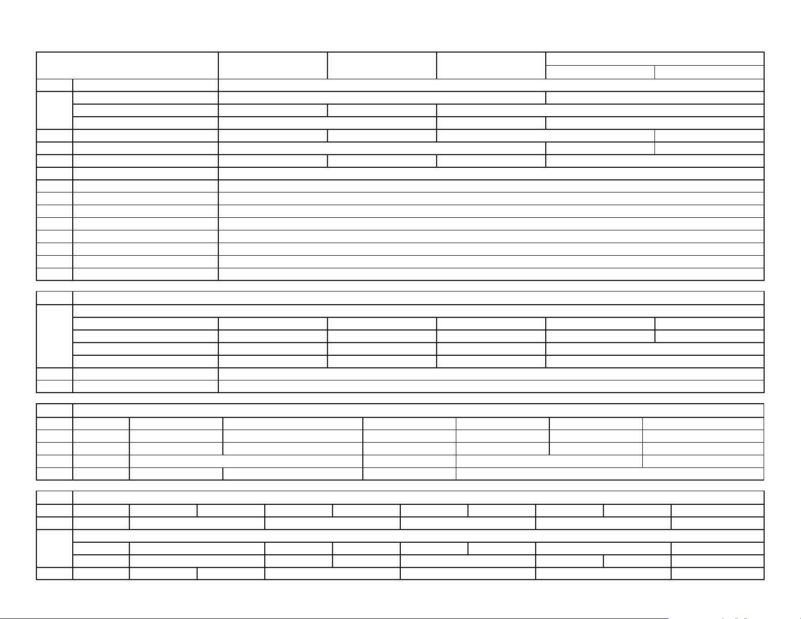
Series 4000 Photoelectric Sensors
Transmitted Beam
All Sensors Retroreflective Polarized Retroflective Standard Diffuse
1 Connection Wire Terminals
Sensing Distance — 274m (900ft)
2
3 Transmitting LED Infrared 940nm Visible Red 660nm Infrared 940nm —
4 Indicators Red: Output Red: Power Red: Output
5 Field of View 1.5_ 2_ 4_ 3_
6 Sensitivity Adjustment Yes
7 Operating Temperature -- 4 0 _Cto+57_C(--40_F to +135_F)
8 Relative Humidity 5%--90%
9 Housing/Lens Material NorylR/Acrylic
10 Operating Environment NEMA 3, 4, 12, 13, IP66
11 Approvals UL listed, CSA certified, and CE marked for all applicable directives
12 Protection False Pulse
13 Vibration 10--55Hz, 1mm amplitude, meets or exceeds IEC 947--5--2
14 Shock 30G, meets and exceeds IEC 947--5--2
15
16
17 Power Consumption 2VA
18 Output Light/Dark Selectable
76mm (3in) Reflector 10.6m (35ft) 7m (23ft) —
White Paper — 3.6m (12ft) —
Select Sensors
Operating Voltage
102--132V AC, 50/60 Hz 42RLU--4000B 42RLU--4200B 42RLP--4000B 42RLL--4000B 42RLR--4000B
195--253V AC, 50/60 Hz 42RLU--4001B — 42RLP--4001B 42RLL--4001B 42RLR--4001B
40--58V AC, 50/60 Hz 42RLU--4002B — 42RLP--4002B —
18--28V AC/DC, 50/60 Hz 20--32V DC 42RLU--4003B — 42RLP--4003B —
Source Receiver
19
Select Optional Plug-In Output Module
20 Catalog Number Control Only 8--670 8--651 8--652 63--115 63--116
21 Type — DPDT EM --Relay (Included) SPNO AC TRIAC SPNO AC/DC FET Open Collector NPN DC Voltage Output Adaptor
22 Load Current — 5A @ 120V AC, 2.5A @ 240V AC 1A @ 24--240V AC 30mA @ 0-- 120V AC 250mA @ 30V DC 30mA @ 17V DC
23 Leakage Current — 2mA 1.0A —
24 Response Time 5ms 10ms On, 15ms Off 8ms 1ms
25
Select Optional Plug-In Control Module
20 Catalog Number 60--1612--1 60-- 1612--2 60--1613 60--1614 60--1625 60-- 1626 60--1660 60--1661 60--1716
26 Function ONE SHOT ON and/or OFF DELAY DELAYED ONE SHOT MOTION DETECTOR PRESENT COUNTER
Adjustable Time Delay
27
28 Adjustable Dwell 0.040--0.25 0.5--1.5 — 0.04--0.250 — 0.040--0.250
ON — 0.05--1.0 0.5--1.5 0.10--1.5 1.0--1.5 — 2--999 Counts
OFF — 0.05--10 0.5--15 — 0.05--1.5 0.5--15 2-- 999 Counts
Page 2

English Español English Español
Operating Distance Selection
The maximum operating distance is based on installing the
sensor in a relatively clean environment. Normal industrial
environments actually range from moderately dusty to extremely dirty. Greater operating margin may be required
which can be obtained by reducing the operating distance of
the control.
Wire Terminals Open Collector NPN
Infrared Infrarrojo DC Voltage Output Adaptor
Visible Red Rojo Visible One Shot
Red Rojo On and/or Off Delay
Output Salida Delayed One Shot
Power Alimentacion Motion Detector
False Pulse Pulsos en Falso Present Counter
10--55Hz, 1mm amplitude, meets or exceeds IEC 947--5-- 2 10--55Hz, 1mm de amplitud, satisface o supera IEC 947--5--2 Counts
30G, meets or exceeds IEC 947--5--2 30G, satisface o supera IEC 947-- 5-- 2 Retroreflective Retrorreflectivo
Light/Dark Selectable Seleccionable Luz/Oscuridad Polarized Retroreflective Retrorreflectivo polarizado
Control Only Standard Diffuse Difusa Normal
DPDT EM-Relay (included) Transmitted Beam Source Fuentes de rayos transmitidos
SPNO AC TRIAC Transmitted Beam Receiver Receptor de rayos transmitidos
SPNO AC/DC FET
Selección de Distancia de Operación
La distancia máxima de operación se basa en la instalación
del sensor en un ambiente relativamente limpio. Los ambientes industriales normales fluctúan entre moderadamente
polvorosos a extremadamente sucios. Es posible que se requiera un margen de operación mayor, el cual puede obtenerse reduciendo la distancia operativa del control.
Indicators
Red on indicates output for all sensors except Transmitted
Beam Source.
Red on indicates power on for Transmitted Beam Light
Source.
Indicadores
El rojo encendido indica la salida en todos los sensores, excepto en las Fuentes de Haz Transmitido.
El rojo encendido indica alimentación presente en las
Fuentes del Luz de Haz Transmitido.
English Español English Español
1 Connection Conexión 15 Select Sensors Elija Sensores
Sensing Distance Dispositivo Sensor 16 Operating Voltage Tensión de Operación
Reflector Reflector 17 Power Consumption Consumo de Alimentación eléctrica
2
White Paper Papel Blanco 18 Output Salida
3 Transmitting (LED) LED de Transmisión 19 Select Optional Plug-In Output Module
4 Indicators Indicadores 20 Catalog Number Número de Catálogo
5 Field of View CampodeVisión 21 Type Tipo
6 Sensitivity Adjustment Ajuste de Sensibilidad 22 Load Current Corriente de Carga
7 Operating Temperature Temperatura de Operación 23 Leakage Current Corriente de Fuga
8 Relative Humidity Humedad Relativa 24 Response Time Tiempo de Respuesta
9 Housing/Lens Material Material del Alojamiento/de la Cubierta/del Lente 25 Select Optional Plug-In Control Module
10 Operating Environment Ambiente de Operación 26 Function Funcion
11 Approvals Aprobaciones
12 Protections Protecciones On Encendido
13 Vibration Vibración Off Apagado
14 Shock Impacto 28 Adjustable Dwell
Adjustable TIme Delay
27
Page 3

Wiring Diagrams
All Sensing Modes Except Transmitted Beam Light Source Transmitted Beam Light Source
Alignment Indicator
#8--651, 8- -652,
Sensitivity Adjustment
Optional Plug-In
Timing and Logic Module
Plug-In Output Relay
Output Relay
Contacts
2C
1C
2NO
1NO
2NC
1NC
L2
L1
Power Supply
Alignment Test Points
Relay Pull-in: 2.5V DC
Relay Drop-Out: 2.0V DC
Optimum 5.0V DC
D
L
Light/Dark
Selection Switch
Output Relay
Contacts
Model 4000B: 120V AC, 50/60Hz
Model 4001B: 240V AC, 50/60Hz
Model 4002B: 48V AC, 50/60Hz
Model 4003B: 24V AC/DC, 50/60Hz
Model 4200B: 120V AC, 50/60Hz
Note: Details regarding connection of Allen-Bradley Series 4000B sensors to Allen-Bradley Programmable Controllers can be found in publication 42 MR-4.0.
Additional Output Connections
and 63--116
2C
2N0
Load
#63--115
1C
1N0
Power Indicator
--
+
No Connection
L1
Power Supply
No Connection
L2
Model 4000B: 120V AC 50/60Hz
Model 4001B: 230V AC 50/60Hz
Typical Response Curves
Retroreflective Polarized Retroreflective Standard Diffuse Transmitted Beam
Operating Margin
100
40
20
10
4
2
1
2.54mm
(0.1in)
76mm (3in)
Reflector
76.2mm
(3in)
0.3m
(1ft)
1.5m
(5ft)
3m
(10ft)
15m
(50ft)
1000
400
200
100
40
20
10
Operating Margin
4
2
1
25.4mm
(1)
152.4mm
(6)
White Paper
216mm x 279.4mm
(8.5 x11)
0.6m
(2)
2.74m
(9)
3m
(10)
6m
(20)
100
40X
20
10
5
3
Operating Margin
2
1
10%
55m
(180)
1000
400
200
100
Operating Margin
40
20
10
4
3
2
1
2.54mm
(0.1in)
76mm (3in)
Reflector
76.2mm
(3in)
0.3m
(1ft)
1.5m
Operating Distance Percent of Maximum Operating DistanceOperating Distance Operating Distance
(5ft)
4.5m
(15ft)
6m
(20ft)
9.1m
(30ft)
15m
(50ft)
82m
(270)
137m
(450)
274m
(900)
Page 4

Dimensions—mm (inches)
(
A
A
79.4
(3.125) Dia.
61.9
(2.437)
LED
Indicator
17.5
(0.687)
86.4
(3.4)
50.8 (2) Dia.
Bolt Circle
7.1
(0.281)
2
(50.8)
203.2
(8)
146
(5.75)
Adjustment Slots
25.4 (1)
3/4 -- 14NPSM
1/4 - 20NC x 5/8 LG
Flanged Hex Head
3 Mounting Holes
120 Apart In Sensor
(3.562)
90.5
247.6
(9.75)
Optional Mounting Bracket
P/N 60--1479
Notes
1. Sensor may be mounted without bracket,
2. Bracket allows 360-degree adjustment.
3. Screws included with mounting bracket.
Note: Do not use lockwashers with supplied whiz-lock mounting screws.
General Purpose Mounting Assembly
#60--1479
3.125 Dia
(079.4)
203.2
(8)
146
17.5
(0.687)
19
(3.4)
50.8 Dia
(2)
Bolt Circle
7.1
(0.281)
(5.75)
Adjustment
Slots
25.4 (1)
50.8 (2)
3/4-- 14NPSM
1/4 - 20NC x 5/8 Lg
Flanged Hex Head
3 Mounting Holes
120 Apart in Control
Note: Do not use lockwashers with whiz-lock mounting screws.
61.9
(2.437)
90.5
(3.562)
1/4-20 X 1/2 Hex Hd Screws
(3) and Lockwashers Supplied
with Mounting Assembly
247.6
(9.75)
LED
Indicator
P/N 60--1479
Optional
Mounting
Bracket
either using 3, 1/4--20NC mtg. holes or on a
3/4 threaded pipe, thread pitch
3/4--14NPSM.
Heavy Duty Mounting Assembly
#60--1665
Bottom
View
1/4-20 X 1/2 Hex Hd Screws
(3) and Lockwashers Supplied
with Mounting Assembly
7.9 (0.312)
Wide Slots
67.5
(2.656)
34.1
12.7
(0.5)
101.6
(4)
127.0
(5)
(1.343)
79.4
(3.125)
106.6
(4.593)
106.4
(4.187)
NEMA 7 and 9 Hazardous Locations Enclosure
#61--4921
152.4
(6.00)
3
4-14
NPT.
Thru
134.92
(5.312)
66.67
(2.625)
66.67
(2.625)
201.60
(7.937)
304.8
(12.00)
55.57
(2.188)
152.4
(6.00)
136.52
(5.375)
111. 14
(4.375)
34.92
(1.375)
101.6
(4)
Dia.
330.2
(13.0)
5/16-18 UNC
X5/16Lg
(4 Mtg. Holes)
14.75
(374.65)
Publication PA--9801
)
February 1998
PrintedinUS
 Loading...