

Page 1

INSTRUCTION SHEET D2Ć3017Ć2
OUTPUT
F
or use with 300, 350, 400 and 500 HP
460 V
General Purpose or Variable Torque
CONT
ACTOR KIT
Models 36C47
AC, ThreeĆPhase Input
AĆC VLSR
Drives
WARNING
BEFORE INST
ALLING
AND/OR
OPERA
TING
THIS KIT, THE QUALIFIED ELECTRICAL
MAINTENANCE
PERSON WHO IS F
AMILIAR
WITH THIS TYPE OF EQUIPMENT AND THE
HAZARDS INVOLVED SHOULD READ THIS
ENTIRE INSTRUCTION SHEET. FAILURE
TO
OBSERVE THIS PRECAUTION COULD REĆ
SULT IN BODILY INJURY.
DESCRIPTION
The Reliance Electric Output Contactor Kit provides a
positive
AĆC VLSR Drive Controller and the Drive Motor. A
controller Start command will cause the contactor to be
energized.
the AĆC Contactor's auxiliary contact does not close (N"
auxiliary
the AĆC Contactor will drop out immediately if the
controller
speed is reached if the controller is set
will drop out after zero speed is reached if the controller is
set
(IET)
Upon
the
clean and dry area until ready to use. The ambient
temperature of the storage area must not exceed 65oC
(149oF) or go below -40oC (-40oF).
disconnect (contactor) between the output of the
The controller start sequence will be inhibited
signal). When the Stop rocker switch is pressed,
is set for coastĆtoĆrest or will drop
for rampĆtoĆrest. When an instantaneous electronic trip
occurs,
receiving, check the contents of the
contents as listed in Table 1. Store this equipment in a
the AĆC Contactor will drop out immediately
out after zero
for coastĆtoĆrest or
kit received with
if
INSTALLATION
NOTE:
mounted in a clean and dry environment. Maximum
ambient temperature must not exceed 40oC outside the
cabinet (55oC inside the cabinet).
WIRE SIZING NOTE: Care should be taken to see that all
interconnecting wiring is sized and installed in
All components of the Output Contactor Kit must be
conformance with the National Electric Code (NEC),
published by the National Fire Protection Association, or
the
Canadian Electrical Code (CEC),
local codes.
Table 1 Complete parts listing.
Description Qty. Part Number
Contactor
Auxiliary Contact (NO)
Connector
Control Transformer
Fuse Block
Fuse
Relay Socket
Relay
Cover
Wire Harness
Wire Harness
Wire Harness
Wire Assembly
Wire Assembly
Wire Assembly
Wire Assembly
Hex Washer Head Screw
.
ăă(5/16Ć18 x 1/2")
Hex Head Cap Screw
ăă(1/4Ć20 x 3/4")
Flat Washer (1/4")
Lock Washer (1/2")
Hex Head Cap Screw
ăă(1/2Ć13 x 1 1/4")
Flat Washer (1/2")
Lock Washer (1/2")
Taptite
Screw (10Ć32 x
Taptite Screw (8Ć32 x 1/2")
Taptite Screw (6Ć32 x 1/2")
Hex Head Cap Screw
ăă(1/4Ć20 x 1 1 /4")
Spacer
TyĆRap
1/2")
and other applicable
1
705310Ć9R
1
76624ĆX
3
610290Ć57A
1
417155ĆS
1
49454ĆA
1
64676Ć1P
1
600434Ć5R
1
600434Ć6R
1
705321Ć15R
1
705337Ć35R
1
801553Ć34R
1
801553Ć35R
1
608809Ć12SA
1
608809Ć12X
1
608809Ć12RX
1
608809Ć12SC
4
601741Ć73B
6
601741ĆC
8
601748Ć1E
8
601748Ć3J
3
601741Ć8AB
3
601748Ć1J
3
601748Ć3N
5
601741Ć63C
2
601741Ć62D
2
601741Ć61D
2
601741ĆAB
2
400684ĆB
10
69306Ć3D
Page 2
1. Disconnect all power to the AĆC VLS Drive before
installing this kit.
DANGER
EQUIPMENT IS AT LINE VOLTAGE WHEN
INPUT DISCONNECT IS ON. THE
THE
INPUT
DISCONNECT MUST BE OFF BEFORE IT IS
TO TOUCH ANY INTERNAL P
SAFE
ARTS
OF
THIS EQUIPMENT. AFTER POWER IS
REMOVED, THE COMMUTATION CAPACIĆ
TORS CAN REMAIN CHARGED. ALLOW
TWO MINUTES BEFORE TOUCHING ANY
INTERNAL PARTS OF THE CONTROLLER.
FAILURE TO OBSERVE THESE PRECAUĆ
TIONS COULD RESULT IN FATAL INJURY.
NOTE: If the Output Contactor Kit and the Control Circuit
Transformer Kit are to be installed, mount the Output
Contactor
Kit normally occupies the same location as the Output
Contactor Kit. The Control Circuit Transformer
relocated as defined in Instruction Sheet D2Ć3014.
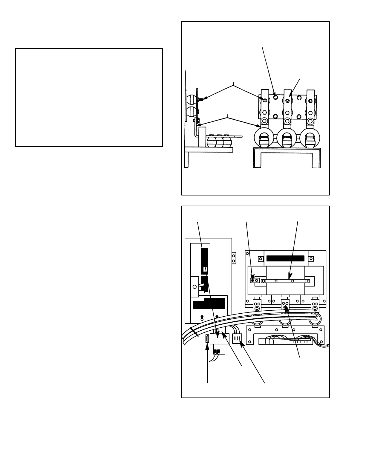
2. Disconnect
Kit first because the
Control Circuit T
ransformer
Kit must be
motor leads T1, T2 and T3 from the output
bus bar assembly (Figure 1). Disconnect bus bars
601, 602 and 603 from the output bus bar assembly
(Figure 1). Remove the output bus bar assembly by
removing the four taptite screws. This assembly will
not
be used while the Output Contactor
Kit is installed.
TAPTITE
SCREW (4)
DISCONNECT MOTOR
LEADS T1, T2, T3
BUS BARS
601, 602, 603
SIDE VIEW
OUTPUT
FRONT VIEW
BUS BAR
ASSEMBLY
Figure 1. Removing output bus bar assembly.
CONTROL
TRANSFORMER
AUXILIARY
CONTACT
CONTACTOR
3.
Snap the Auxiliary Contact (76624Ć
X) into the cavity on
the front left of the Contactor (Figure 2). Secure with
the captive lock screw provided.
4. Using the four furnished 5/16Ć18 x 1/2" hex washer
head
screws, mount
the Contactor (705310Ć9R) in the
controller as shown in Figure 2. The mounting holes
are preĆdrilled in the back panel.
5. Using the six furnished 1/4Ć20 x 3/4" hex head cap
screws and six 1/4" flat washers and 1/4" lock
washers, install the three identical Connectors
(610290Ć57A) to the line side of the Contactor. See
Figure 2.
6. Using
the three furnished 1/2Ć13 x
1 1/4" hex head cap
screws and the three 1/2" flat washers and 1/2" lock
washers, attach the Connectors to the 601, 602 and
603 bus bars.
7. Using
four of the furnished 10Ć32 x 1/2" taptite screws,
mount the Control Transformer (417155ĆS) to the left
of
the motor overload relay block as shown in Figure 2.
The
mounting holes are preĆdrilled in
the back panel.
(It might be helpful to preĆthread the screws in the
mounting holes.)
8. connect the metal jumper supplied with the
transformer
H2)
on the input side of the transformer
between the two center
terminals (H
. See Figure
3
and
2.
CONNECTOR (3)
METAL
JUMPER
FUSE
IN FUSE BL
OCK
MOTOR OVERL
RELA
Y BL
OCK
Figure 2. Controller right bay components.
OAD
Page 3
ă9. Using the two furnished 8Ć32 x 1/2" taptite screws,
mount the Fuse Block (49454ĆA) to the left of the
Control Transformer. See Figure 2. The mounting
holes are preĆdrilled in the back panel. Insert the 3.2
F
use (64676Ć1P), 250Ćvolt, UL Class RK5) into the
amp
Fuse Block.
115
VOL
T
TERMINAL B
RELA
RELA
OARD
Y IN
Y SOCKET
OUTLET AIR
DUCT REMOVED
SIDE W
OPENINGS
ALL
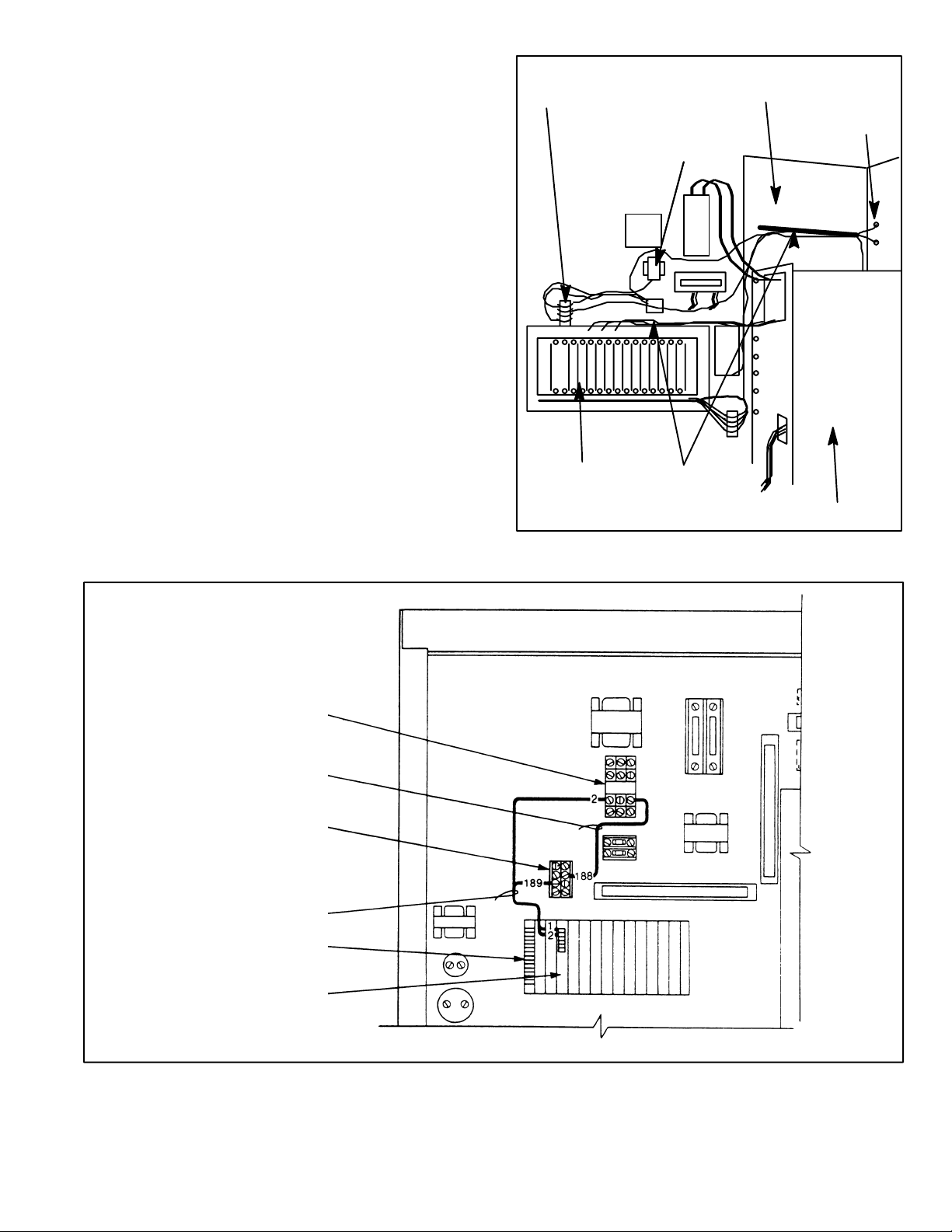
10. Using
two
furnished 6Ć32 x 1/2" taptite screws, mount
the Relay Socket (600434Ć5R) in the left bay of the
controller as shown in Figure 3. The mounting holes
are preĆdrilled in the back panel. Insert the Relay
(600434Ć6R) into the Relay Socket.
11. Remove
the outlet air duct (Figure 3) by loosening the
nine hex head cap screws. Set aside for later
reĆinstallation.
12. Remove
the factory
Ćinstalled wiring between
terminals
43 and 53 on TB1 and terminals 1 and 2 on the
faceplate of the CSS-* card. See Figure 4.
13. Connect Wire Harness 705337Ć35R. Connect leads
189 and 2 to terminals 1 and 2, respectively, on the
faceplate
of the CSS- card. Connect the other end of
lead 189 to the 115Ćvolt terminal board and the other
end
of the lead 2 to the Relay
* The
fourth letter of this regulator PC board designation indicates a difference in the PC board.
Refer to the specific controller to identify the fourĆletter PC board designation.
. See Figures 3, 4 and 7.
CS
S -*CARD
FACEPLATE
CHANNELS
POWER MODULE
Figure 3. Controller left bay components.
RELAY
WIRE
AS
SEMBLY
608809Ć12SA
115 VOL
TERMINAL
WIRE HARNES
705337Ć35R
CSS-*CARD
FACEPLATE
* The fourth letter of this regulator PC board designation indicates a difference in the PC board. Refer to the specific controller to identify the fourĆletter PC board designation .
T
BOARD
S
TB1
Figure 4. Connecting Wire Harness 705337Ć35R and Wire Assembly 608809Ć12SA.
14. Connect Wire Assembly 608809Ć12SA (labeled 188)
between the 115Ćvolt terminal board and the Relay.
See Figures 4 and 7.
15. Connect Wire Assembly 608809Ć12X (the green
ground wire labeled 289) to the Control Transformer.
Using the remaining 10Ć32 x 1/2" taptite screw,
Page 4

connect the other end to the hole preĆdrilled in the
back panel below the Control Transformer. See
Figures 2, 5 and 7.
16. Connect Wire Assembly 608809Ć12RX (labeled 288)
between the Fuse and the Control Transformer. See
figures 2, 5 and 7.
17. Connect Wire Assembly 608809Ć12SC between
terminals 1 and 3 on the Contactor terminal board.
See Figure 5.
18. Referring
to Figures 6 and 7 and T
able
2, connect W
ire
Harness 801553Ć34R beginning in the left bay of the
controller. Route the harness thru the back channel
located above the power module, thru the bottom
opening at the top of the side wall, thru the back
vertical channel to the respective connection points.
Note that leads 11 and 289 will route thru the back
channel located above the Control Transformer.
Harness
Lead
Numbers
(both ends)
388
ă11
381
383
289
Control T
Control T
Control T
From To
Fuse
Relay
ransformer H
ransformer H
ransformer X
1
4
2
Relay
L1 on Contactor
T
ransformer Line F
T
ransformer Line F
L2 on Contactor
use
use
19. Referring to Figures 6 and 7, connect Wire Harness
801553Ć35R to the Auxiliary Contact installed in Step
3. Route the harness in the
front channel (outermost)
located above the Control Transformer, up the front
vertical channel,
thru the top opening at the top of the
side wall, thru the front channel located above the
power module, down the front vertical channel, thru
the
horizontal channel located above the regulator
, to
terminals 43 and 53 on TB1 of the regulator.
20. Support the wire harnesses and assemblies as
necessary with the furnished tyĆraps.
CONTROL
TRANSFORMER
FUSE
WIRE
AS
SEMBLY
608809Ć12RX
WIRE AS
SEMBLY
608809Ć12X
WIRE AS
608809Ć12SC
CONTACTOR
SEMBLY
Figure 5. Connecting Wire Assemblies 608809Ć12X, Ć12RX and Ć12SC.
Page 5

21.
Replace the outlet air duct over the nine loosened
head
cap screws making sure all wiring is clear of
hex
the
duct. Tighten the screws.
22. Using the hardware supplied with the Contactor,
reconnect
motor leads T1, T2 and T3 to terminals 1T1,
1T2, and 1T3, respectively, on the load side of the
Contactor.
23. Using the two supplied spacers, the two 1/4Ć20 x 1
1/4"
hex head cap screws, and the two remaining 1/4"
flat washers and 1/4" lock washers; install the Cover
(705321Ć15R) on the Contactor.
24. ReĆapply power the AĆC VLS Drive.
WIRE HARNES
801553Ć35R
S
CONTACTOR
WIRE
HARNES
801553Ć34R
TB1
REGULATOR
RELAY
Figure 6. Connecting Wire Harnesses 801553Ć34R and Ć35R.
S
FUSE
TRANSFORMER
CONTROL
AUXILIARY
CONTACT
Page 6

TO
TB1
REGULATOR
TO 115Ć
VOLT
TERMINAL
BOARD
TO
TRANSFORMER
LINE
FUSES
* The fourth letter of this regulator PC board designation indicates a difference in the PC board. Refer to the specific controller to identify the fourĆletter PC board designation .
Figure 7. Electrical diagram.
Page 7

Page 8

U.S. Drives Technical Support
Tel: (1) 262.512.8176, Fax: (1) 262.512.2222, Email: support@drives.ra.rockwell.com, Online: www.ab.com/support/abdrives
Trademarks not belonging to Rockwell Automation are property of their respective companies.
Publication D2-3017-2 – July 1990 Copyright © 1990 Rockwell Automation, Inc. All Rights Reserved. Printed in USA.
 Loading...