

Page 1
INSTRUCTION SHEET
DĆ3894Ć1
Dynamic Braking Kit
Model 34C473
For use with 5, 7Ć1/2 and 10 HP
General Purpose AĆC VKSR Drives
ThreeĆPhase Input
Before installing and/or adjusting this kit, the quali
fied electrical maintenance person who is familiar
with
this type of equipment and the hazards involved
should read this entire instruction sheet.
DESCRIPTION
The Reliance Electric Dynamic Braking (DB) Kit is deĆ
signed
and/or
to provide rapid
enable the AĆC V
150% intermittent braking to the motor. The kit dissiĆ
in the form of heat, the power regenerated by the
pates,
motor during deceleration or intermittent overhauling
The power is dissipated by resistors mounted in
loads.
the NEMA 1 side (right side) of the AĆC VKS Drive Con
cabinet.
troller
This kit also provides adjustable motoring and regenĆ
erative current limit circuitry. The adjustment range of
the motoring current control is approximately 40 to
of the drive controller fullĆload current (not of the
150%
motor
fullĆload current rating). The adjustment range of
the
regeneration current control is approximately 80 to
150% of the drive controller fullload current (not of the
motor fullĆload current rating). The use of this kit does
not affect the operation of the drive's instantaneous
electronic
trip current protection.
deceleration of the drive motor
KSR
Drive Controller to provide
Ć
The following are design specifications for this kit:
DB Resistor rating: 500 watts
2
WR
=
3: 6 starts/stops per minute from 1800 RPM
2
WR
=
6: 3 starts/stops per minute from 1800 RPM
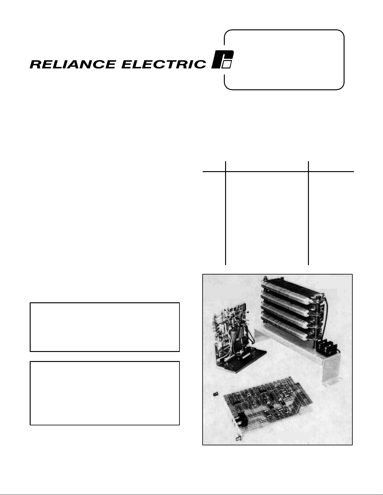
KIT CONTENTS
Qty. Description Part
1
DB
Resistor Assembly
DB Base Driver Assembly
1
W
1
1
1
Ć
2
2
4
2
2
ire Harness
W
ire Harness
W
ire Harness
Gasket
eps Nut
K
#10Ć32 x 3/8 T
#10 Internal T
Lock W
asher
aptite Screw
ooth
#10Ć32 x 3/8 Round Head
Machine Screw
CLSA Board
1
DB BASE DRIVER
ASSEMBLY
Number
801450Ć3R
77596Ć88R
705337Ć21R
608808Ć63TD
608808Ć63TC
417194Ć12C
401599Ć11E
601741Ć63B
601748Ć4J
601742Ć6E
0Ć52862
DB RESISTOR
ASSEMBLY
CAUTION:
set
below a particular motor's
Should the regenerative
minimum current lev
current limit be
el, the regenerative current limit circuitry may proĆ
the motor
hibit
from decelerating. Reset the regen
erative current limit as described under ADJUSTĆ
MENTS"
CAUTION: DO
DB
bly
age
ate
in this instruction sheet.
NOT
operate the controller with
Resistor Assembly and DB
Base Driver Assem
the
connected and the CLSA Board removed. Dam
to equipment will occur
. If it is desired to oper
the controller without dynamic braking, removal
of the threeĆpin plug (wire harness 608808Ć63TD)
from the DB Base Driver Assembly PC Board will
disable
The
diode
ing
At
high rates of deceleration, the LED will appear to be
ON
this kit.
DB Base Driver PC Board includes a light emitting
(LED) that indicates dynamic braking action. Dur
normal deceleration, the LED will cycle ON and OFF
continuously
.
Ć
Ć
Ć
Ć
Ć
CLSA BOARD
Ć
.
Figure 1. Kit contents.
Page 2
INSTALLATION
1. Disconnect
ler.
EQUIPMENT IS AT LINE VOLTAGE WHEN AĆC
POWER IS CONNECTED TO THE AĆC VKS
DRIVE CONTROLLER. ALL UNGROUNDED
CONDUCTORS
BE
DISCONNECTED FROM THE
BEFORE IT IS SAFE TO TOUCH ANY INTERNAL
PARTS
REMOVED, USE A VOLTMETER TO VERIFY
THAT THE DĆC BUS FILTER CAPACITORS ARE
DISCHARGED BEFORE TOUCHING ANY INĆ
TERNAL
all power to the AĆC VKS Drive Control
DANGER
OF THE AĆC POWER LINE
CONTROLLER
OF
THIS EQUIPMENT
P
ARTS OF THE CONTROLLER.
. AF
TER POWER IS
MUST
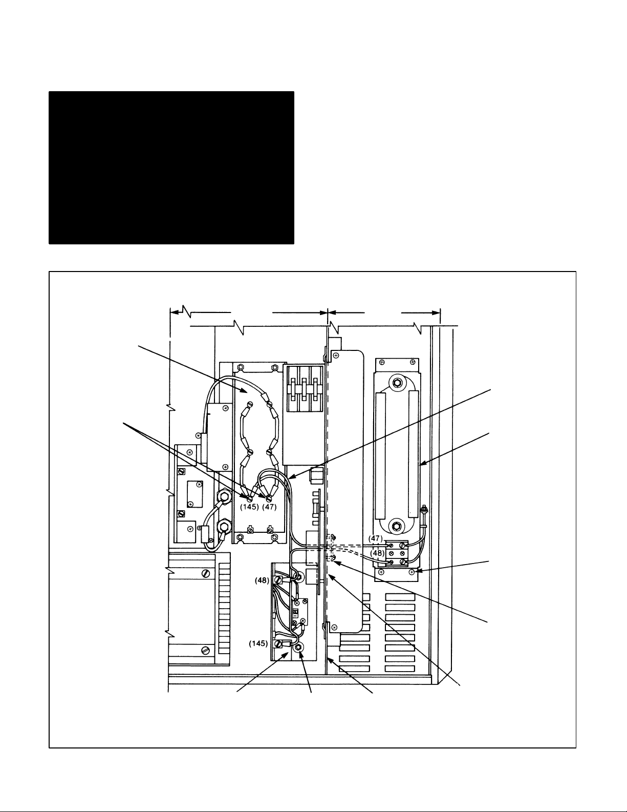
2. Using an 11/32'' wrench, remove the lower cover
plate and gasket from the vertical barrier on the
1 side (Figure 2). Discard the gasket.
Ć
NEMA
NOTE: This cover plate and gasket are behind the
Variable
oltage D
ĆC Supply (S
Ć3 Assembly). At the
V
user's discretion, the Variable Voltage DĆC Supply
can be removed to gain access to this area.
3. Install
over the studs on the vertical barrier the two
supplied gaskets (part 417194Ć12C).
4. ReĆinstall
the cover
plate with hardware removed in
Step 2.
5. Install the nonĆlugged ends of wire harness pair)
705337Ć21R (the only harness not of twisted pair)
thru the gasket and cover plate from the NEMA 12
side
(left side) by pushing lead 47 thru the top hole
in the gasket and lead 48 thru the bottom hole.
two leads will be connected later in this pro
These
Ć
cedure.
CAPACITOR
COVER REMOVED
CAPACITOR
TERMINALS
NEMA 12
NEMA 1
WIRE HARNESS
705337Ć21R
DB RESISTOR
ASSEMBLY
TAPTITE
SCREW
DB BASE DRIVER
Figure 2. Initial installation details.
ASSEMBLY
STUD WITH
KEPS NUT
VERTICAL
BARRIER
COVER PLATE
AND GASKET
VARIABLE
VOLTAGE
DĆC SUPPLY
Page 3
6. Remove
itor
the filter capacitor cover and locate
capac
terminals 145 (bottom left) and 47 (bottom right)
(Figure 2).
7. Remove the #10 screws from capacitor terminals
and 47. Connect leads 145 and 47
145
of wire har
ness part 705337Ć21R to capacitor terminals 145
and
47, respectively
8.
ReĆinstall the filter capacitor cover
. Reinstall the #10 screws.
.
9. Locate the four preĆdrilled holes in the back of the
1 side (right side)
NEMA
of the enclosure. Start the
four supplied #10Ć32 x 3/8'' taptite screws into
holes but do not tighten fully (Figure 2).
these
10. Position the keyhole slots of the DB Resistor AsĆ
sembly (part 801450Ć3R) over the taptite screws.
Tighten
11. Connect
er
nals
sembly
12. Connect
all four screws.
the leads pushed thru the gasket and
plate in Step 5. Connect leads
47 and
48, respectively
47 and 48 to termi
, on the DB Resistor As
(Figure 2).
one end of wire harness part 60880863T
cov
(the single orange and black twisted pair) to the
SNUBBER
ON" connections on
the regulator mo
therboard (Figure 3). Polarity is Important. The
orange
lead connects to the plus (+)
and the black
Ć
lead
connects
to the minus (-). Let the other end of
the harness rest along the enclosure floor unconĆ
nected
13. Locate
Ć
side (left side) of the enclosure (Figure 2). W
until connection later in this procedure.
the studs in
the lower back of the NEMA 12
ith the
PC board on the left, position the Base Driver AsĆ
sembly
provided
bly
(part 77596Ć88R) over the studs. Using the
keps nuts,
install the Base Driver Assem
on the studs.
Ć
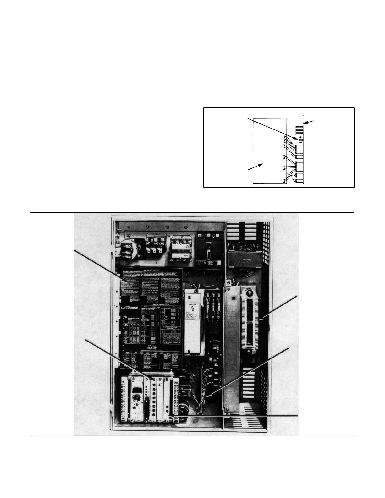
14. Remove the phase module cover (Figure 4).
Connect
SNUBBER ON"
CONNECTION
one end of wire harness part 608808Ć63TD
MOTHERBOARD
(+) ORANGE
(-) BLACK
Ć
Ć
Ć
C
Ć
PSPC BOARD ON
RIGHT SIDE OF
REGULATOR
Figure 3. Location of SNUBBER ON" connections
on motherboard.
PHASE
MODULE
COVER
VSAA BOARD
DB RESISTOR
ASSEMBLY
DB BASE DRIVER
ASSEMBLY
CLSA BOARD
Figure 4. Dynamic Braking Kit installed.
Page 4

to the top set of three pins on the lower right Base
PC Board. Connect the other end
Driver
ness
to the top set of three pins on the DB Base
Assembly PC Board (Figure 5).
er
plugs
is not important.
ule cover
15.
Connect the end of wire harness 608808Ć63T
unconnected
Base
.
in Step 12 to the pair of pins on the DB
Driver Assembly PC Board (Figure 5).
ReĆinstall the phase mod
Polarity
of the har
Driv
of these
C left
Install
the plug with the orange wire aligning with the
top pin.
16. Connect the end of wire harness 705337Ć21R left
unconnected in Step 5 to the DB Base Driver AsĆ
sembly
PC Board. Using the
supplied internal tooth
lock washers and #10Ć32 x 3/8 round head maĆ
chine screws, connect leads 48 and 145 to termiĆ
nals 48 and 145, respectively (Figure 5).
NOTE: If the Variable Voltage DĆC Supply was reĆ
moved
LOWER RIGHT
BASE DRIVER
PC BOARD
in Step 2, it must be reĆinstalled
at this time.
Ć
Ć
Ć
CAUTION: The DB Resistor Assembly and DB
Base Driver Assembly are now installed. DO NOT
operate
0Ć52862)
namic
harness
the controller
installed. If it is desired to disable the
Braking Kit, remove the threeĆpin plug
608808Ć63TD) from the DB Base Driver
without the CLSA Board (part
Dy
(wire
As
Ć
Ć
sembly PC Board (installed in Step
17. Install
the CLSA Board in the far right slot of the reg
ulator
(Figure 4).
Ć
18. ReĆapply power to the AĆC VKS Drive. The LED on
DB Base Driver Assembly PC
the
Board should be
off. If the LED is on, check the wire harness
608808Ć63TC connections between the motherĆ
board
and the DB Base Driver
Assembly PC Board.
TOP SET OF
3 PINS
BOTTOM SET
OF 3 PINS
WIRE HARNESS
608808Ć63TC
BOTTOM SET
OF 3 PINS
WIRE HARNESS
608808Ć63TD
(POLARITY NOT
IMPORTANT)
WIRE HARNESS
705337Ć21 R
48
DB BASE DRIVER
ASSEMBLY
145
Figure 5. DB Base Driver Assembly Installation details.
Page 5

ADJUSTMENTS
DANGER
ADJUSTMENTS ARE MADE WITH POWER ON.
EXERCISE EXTREME CAUTION WHEN PERĆ
FORMING THESE ADJUSTMENTS AS HAZĆ
ARDOUS VOLTAGE EXISTS.
the acceleration rate
5. If
the Accel Rate potentiometer on the VSAA Board
about 1/4th turn counterclockwise and check the
acceleration according to Step 3. Continue to reĆ
peat this procedure until the desired acceleration
is reached.
rate
Setting the Regen Current Limit
of the motor is too fast, adjust
Dynamic
able.
of
motoring and regenerative current.
1. Adjust
2. Adjust
Setting the Motoring Current Limit
3. Turn
4. If the acceleration rate of the motor is not fast
braking action is automatic and is not
Current limit controls are provided for adjustment
both the Motoring
gen Current Limit potentiometers on the CLSA
Board
to the approximate
o'clock
tentiometers on the VSAA Board fully clockwise
(max
ator's Control Station fully clockwise (max speed)
and
eration
rent Limit is adjusted properly. If the acceleration
rate
to Step 5.
enough,
motor to stop. Adjust the Motoring Current Limit
1/8th turn clockwise and, with the Speed Setting
potentiometer still at maximum speed, press the
Start rocker switch. Continue to repeat this proceĆ
dure
NOTE:
and
been turned too far clockwise. (The Motoring CurĆ
rent
ic Trip [IET] current setting of the controller.) Reset
the drive by depressing the Stop rocker switch on
the
ing Current Limit a little counterclockwise and reĆ
peat the procedure described in Step 3.
position).
both the Accel Rate and the Decel Rate po
rate) (Figure 4).
the Speed Setting potentiometer on the Oper
press
the Start rocker switch. If the rate of accel
of the
motor is as desired, the Motoring Cur
is not fast enough, go to Step 4; if too fast, go
press the Stop rocker switch and allow the
until the desired acceleration
If a point is reached where the drive shuts off
coasts to a stop, the Motoring Current Limit
Limit
has exceeded the Instantaneous Electron
Operator's Control Station. Then turn the Motor
Current Limit and the Re
center of their ranges (12
rate is reached.
adjust
has
CAUTION:
set
Ć
Ć
Ć
Ć
Ć
Ć
Ć
Ć
below a particular motor's
el, the regenerative current limit circuitry may proĆ
hibit
erative
6. Set
tor's Control Station fully clockwise (max speed)
and
turn the Speed Setting potentiometer fully
clockwise
the
adjusted correctly. If the deceleration rate is too
long,
NOTE:
tended
controller to provide long deceleration times.
7. If the deceleration rate of the motor is too long, inĆ
crease the Regen Current Limit adjustment 1/8th
turn
in
Step 6. Continue this procedure until the
deceleration
NOTE:
and coasts to a stop, the Regen Current Limit has
been
Limit has exceeded the Instantaneous Electronic
Trip
drive by depressing the Stop rocker switch on the
Operator's Control Station. Then turn the Regen
Current Limit a little counterclockwise and repeat
the procedure described in Step 6.
8. If
the deceleration rate
just
about
celeration according to Step 6. Continue to repeat
this procedure until the desired deceleration is
reached.
Should the regenerative
the motor
current limit as described below
the Speed Setting potentiometer on the Opera
run the drive at maximum speed. Then quickly
motor is as desired, the Regen Current Limit
go to Step 7; if too short, go to Step 8.
clockwise and repeat the procedure
turned too far clockwise.
[IET] current setting of the controller
the Decel Rate potentiometer on the
from decelerating. Reset the regen
(min speed). If the rate of deceleration of
The Regen Current Limit adjustment is not in
to replace the Decel Rate adjustment on the
time is reached.
If a point is reached where the drive shuts off
of the motor is too short, ad
1/4 turn counterclockwise and check the de
current limit be
minimum current lev
.
counter
described
desired
(The Regen Current
.) Reset the
controller
Ć
Ć
Ć
Ć
is
Ć
Ć
Ć
Page 6

DB THRESHOLD
VSAA PIN 35
VSAA PIN 12
VSAA PIN 41
CURRENT
SHUNT
COMPARATOR
WITH
HYSTERESIS
JAM VOLTAGE
CONTROL
DB SIGNAL TO
SNUBBER BASE
DRIVER SWITCH
LVTU JAM
VSAA PIN 42
LVTU CLAMP
VSAA PIN 43
PSPC ISOLATED
POWER FOR
CURRENT LIMIT
Figure 6. Functional block diagram.
CLSA B/M 0Ć52862
Page 7

Page 8

U.S. Drives Technical Support
Tel: (1) 262.512.8176, Fax: (1) 262.512.2222, Email: support@drives.ra.rockwell.com, Online: www.ab.com/support/abdrives
Trademarks not belonging to Rockwell Automation are property of their respective companies.
Publication D-3894-1 – 1992 Copyright © 1992 Rockwell Automation, Inc. All Rights Reserved. Printed in USA.
 Loading...