

Page 1
Full Voltage Non-Reversing Starter
NEMA Size 0, 1, 2
(Cat 309-AO_; -BO_; -CO_)
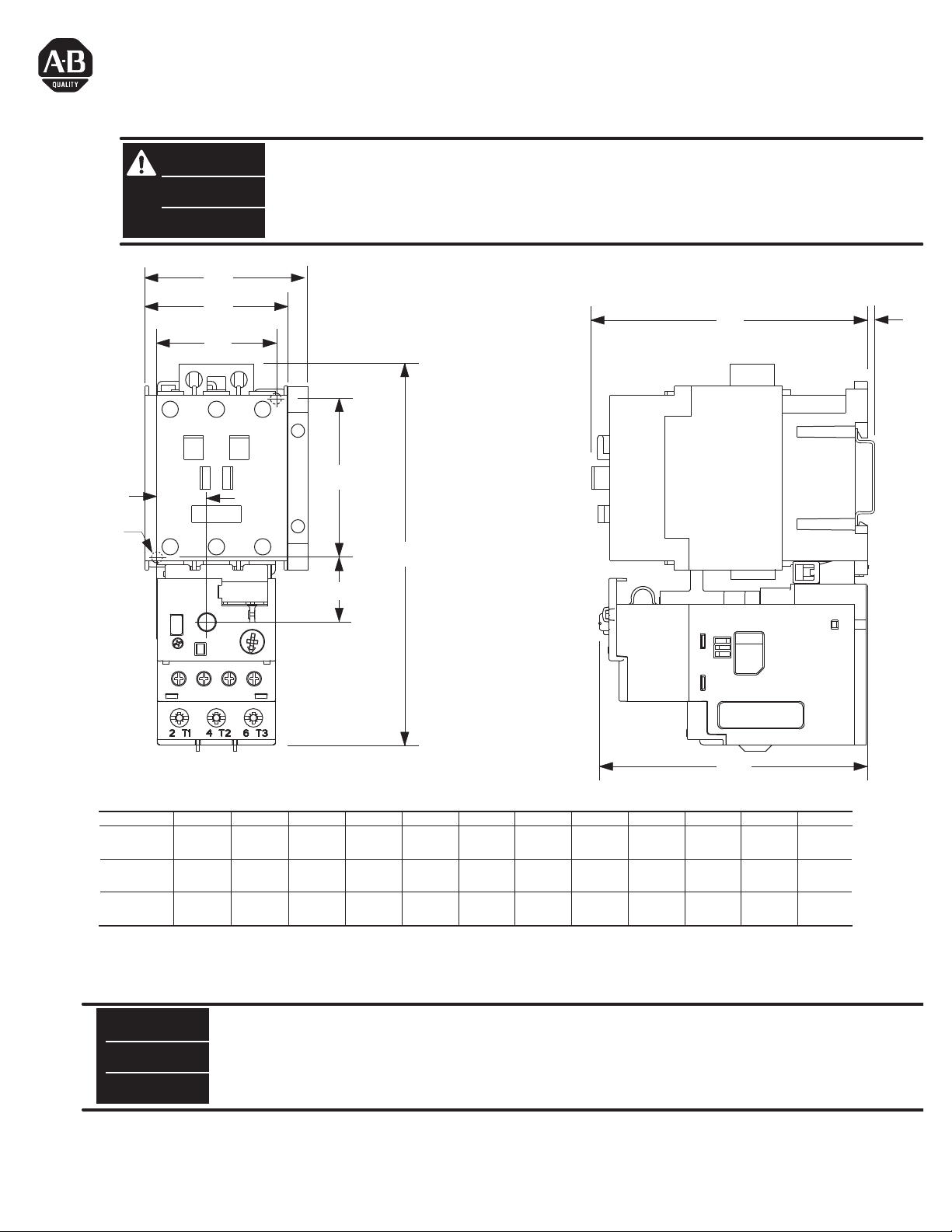
Dimensions are shown in inches (millimeters). Dimensions are not intended to be used for manufacturing purposes.
WARNING
AVERTISSEMENT
ADVERTENCIA
To prevent electrical shock, disconnect from power source before installing or servicing. Install in suitable enclosure. Keep free from
contaminants. (Follow NFPA70E requirements)
Avant le montage et la mise en service, couper l'alimentation secteur pour éviter toute décharge. Prévoir une mise en coffret ou armoire
appropriée. Protéger le produit contre les environnements agressifs. (Vous devez respecter la norme NFPA70E).
Desconéctese de la corriente eléctrica, antes de la instalación o del servicio, a fin de impedir sacudidas eléctricas. Instálelo en una caja
apropiada. Manténgalo libre de contaminantes. (Cumpla con los requisitos NFPA70E).
A2
A1
H
J
F
G
E
ø
K
B
D
CAT. NO. A2 B C D E F G H J øK
309-AO_
309-BO_
309-CO_
in
(mm)
in
(mm)
in
(mm)
A1
1.76
(45)
- -
- -
Electronically Controlled DC-Coil Only
NOTICE
REMARQUE
AVISO
PN-33402
DIR 10000032277 (Version 03)
Printed in U.S.A.
(IEC / EN 60947-1) This product has been designed for environment A. Use of this product in environment B may cause unwanted
electromagnetic disturbances in which case the user may be required to take adequate mitigation measures.
(IEC / EN 60947-1) Ce produit on l’utilise dans l’environnement A. L’utilisation de ce produit dans l’environnement B peut créer des
perturbations électromagnetiques. En ce cas, l’utilisateur doit prendredes mesures pour diminuer les perturbatione électromagnetiques.
(IEC / EN 60947-1) Este producto se puede usar en el ambiente A. El uso en el ambiente B puede causar perturbaciones electromagnéticas. En
ese caso de uso, el usuario debe tomar medidas de diminuir las perturbaciones electromagnéticas.
- -
2.12
(54)
2.48
(63)
5.77
(147)
5.77
(147)
5.77
(147)
3.35
(85.2)
3.98
(101)
3.98
(101)
0.96
(24.5)
0.96
(24.5)
0.96
(24.5)
0.55
(13.9)
0.55
(13.9)
0.74
(18.4)
1.38
(35)
1.38
(35)
1.77
(45)
2.36
(60)
2.36
(60)
2.36
(60)
3.40
(86.5)
4.09
(104)
4.09
(104)
C
0.08
(2)
0.08
(2)
0.08
(2)
0.17
(4.5)
0.17
(4.5)
0.17
(4.5)
Page 2
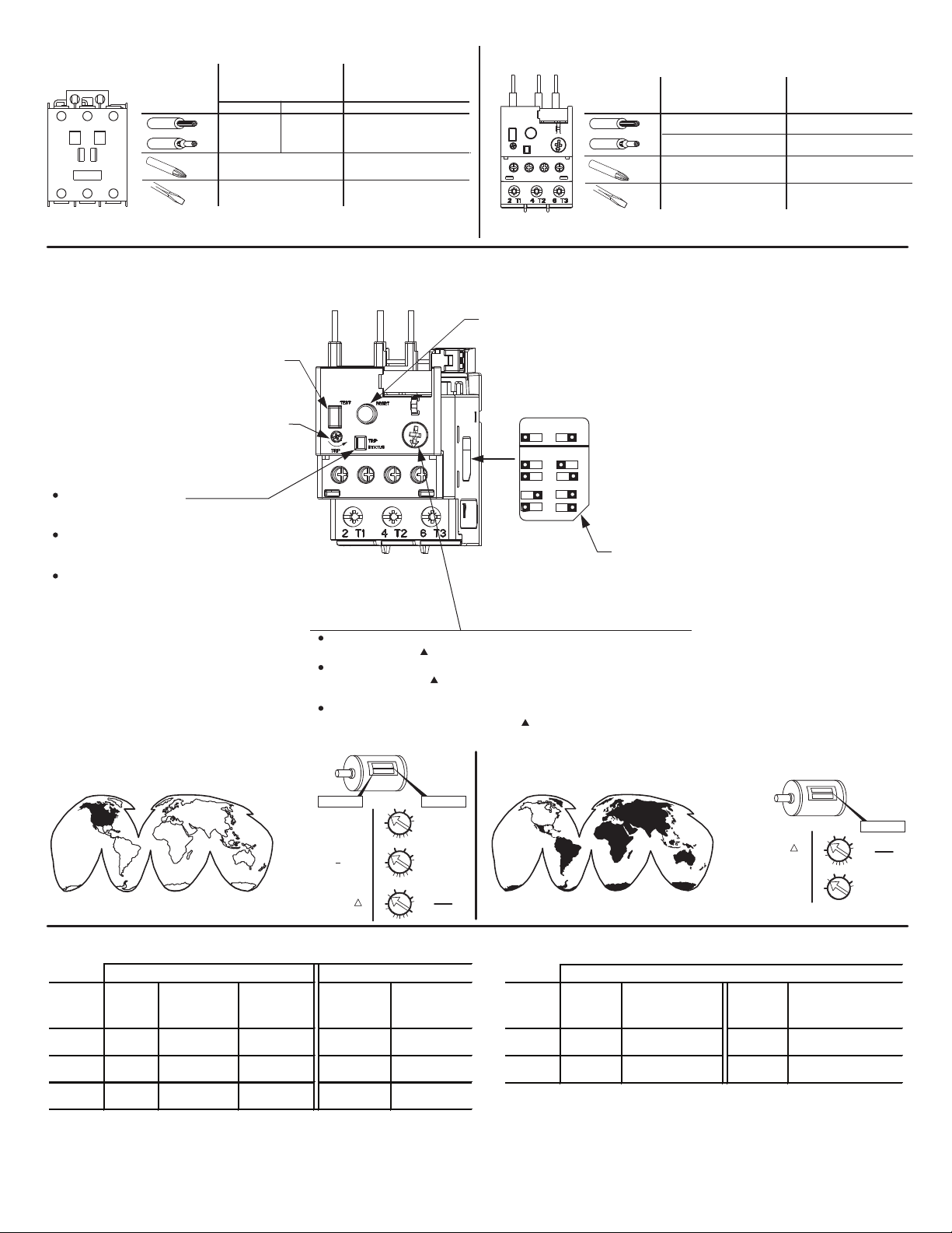
Main Connections
Raccordements Principale
Collegamenti Principale
Size 0
#16 - 10 AWG
13 - 22 lb-in
Size 1 and 2
#14 - 4 AWG
22 - 31 lb-in
#2
Control Connections
Bornes de Commande
Morsetti di Commando
Size 0, 1 and 2
#16 - 12 AWG
9 - 13 lb-in
#1
Main Connections
Raccordements Principale
Collegamenti Principale
#14 - 6 AWG
1x
18 - 26 lb-in
#14 - 6 AWG
2x
24 - 36 lb-in
#2
Control Connections
Bornes de Commande
Morsetti di Commando
#24 - 10 AWG
1x
4 - 6 lb-in
#24 - 12 AWG
2x
4 - 6 lb-in
#1
1 x 6 mm
E1 Plus Features
Caractéristiques du E1 Plus
Características del E1 Plus
Push To Test
Enfoncer pour tester
Presione para probar
Faire pivoter pour déclencher manuellement
Rotar para disparar manualmente
Trip Indicator Window
Yellow indicator not visible: Not Tripped.
Yellow indicator visible: Tripped.
Fenêtre d'indicateur de déclenchement
Indicateur jaune non visible : pas de déclenchement
Indicateur jaune visible : déclenchement
Ventana indicadora de disparo
Indicador amarillo no visible: No disparado
Indicador amarillo visible: Disparado
Rotate to Manually Trip
0.6 x 3.5 mm
Push to Reset
Enfoncer pour réinitialiser
Presione para reiniciar
193*-EE
RESET MODE
A
TRIP CLASS
10
20
To adjust trip current, turn dial until the desired current is
aligned with the pointer. Trip rating is 120% of dial setting.
Pour régler l'intensité de déclenchement, tournez le cadran jusqu'à
ce que le pointeur soit sur l'intensité voulue. La valeur nominale
de déclenchement est de 120% du réglage cadran.
Para ajustar la corriente del disparo, gire el dial hasta que la corriente
deseada esté alineada con la marca . La capacidad nominal del
disparo es el 120% del posicionamiento del dial.
A = Automatic/Manual Reset Mode
M
A = Mode de réinitialisation automatique/manuel
A = Modo de reinicio automático/manual
15
M = Manual Reset Mode
M = Mode de réinitialisation manuel
30
M = Modo de reinicio manual
Selectable Trip Class
Classe de déclenchement sélectionnable
Clase de disparo seleccionable
1 x 6 mm
0.6 x 3.5 mm
S.F. _ _ FLA _ _
S.F. < 1.15
S.F. 1.15
Y
High Fault RatingsStandard Fault Ratings
Starter Short Fuse Rating Circuit Short Fuse Rating
Catalog Circuit Class K5 Breaker Circuit Class J
Number Rating 600V Max. Rating Rating 600V Max.
309-AO* 5,000 A. 40 A.
309-BO* 5,000 A. 100 A.
309-CO* 5,000 A. 150 A.
40 A.
480 V max.
100 A.
600 V max.
125 A.
600 V max.
100,000 A.
100,000 A. 50 A.
100,000 A. 70 A.
30 A
Class CC or J
PN-33402
DIR 10000032277 (Version 03)
= .9 X FLA
= 1 X FLA
FLA
=
1.73
STAR DELTA (Y )
DOL
High Fault Ratings
Starter Short Circuit Breaker Short Circuit Breaker
Catalog Circuit Rating Circuit Rating
Number Rating 480 V Max. Rating 600 V Max.
309-BO* 50,000 A. 50 A. 30,000 A. 50 A.
309-CO* 50,000 A. 50 A. 30,000 A. 50 A.
(2)
FLA _ _
FLA
=
1.73
= 1 X FLA
Page 3

Wiring Diagram
Schéma de câblage
Diagrama de cableado
3 Phase Lines
A1 A2
3-Wire Control
START
2 Station
START
1L1
L1
1L2 1L3
L2
L3
STOP
STOP
3
2
1, L1
3
13
2-Wire Control
14
2
T1
95 964
T1
2
5 97 98
T1
T2
4
T2
T2 T3
T3
3-Wire Control
START
6
T3
STOP
3
1, L1
3
2
1, L1
Diagram reference ‘1’ refers to a
termination on a voltage source
MOTOR
other than the contactor
(eg. control circuit fuse block or
control circuit transformer)
NOTICE
Additional control circuit overcurrent protection may be required. Refer to the National Electrical Code. The current rating of the control circuit
conductors furnished with this device is 15 Amps. Use 75° C copper wire only.
Maintain this equipment in accordance with guidelines of NFPA-70B, Electrical Equipment Maintenance.
Select the motor branch circuit overcurrent protection in accordance with the National Electrical Code or the Canadian Electrical Code; except, use
fuses only.
PN-33402
DIR 10000032277 (Version 03)
(3)
Page 4

Renewal Parts
Coils
Overload Relays
Auxiliary Contact
AC Coil
Voltage
24 V
50 / 60 HZ
110 V / 50 HZ
120 V / 60 HZ
220 V / 50 HZ
240 V / 60 HZ
440 V / 50 HZ
480 V / 60 HZ
550 V / 50 HZ
600 V / 60 HZ
Current
Range
1.0 - 5.0 Amps
5.4 - 27 Amps
5.4 - 27 Amps
9 - 45 Amps
Coil Part No.
Size 0 Size 1 Size 2
TA855
TA473
TA474
TA475
TA476
TC855
TC473
TC474
TC475
TC476
Catalog No.
Size 0 Size 1 Size 2
193-EECB
193-EEEB
193-EEED
100-SB10 100-SB10
TD855
TD473
TD474
TD475
TD476
193-EEFD
PN-33402
DIR 10000032277 (Version 03)
Printed in U.S.A.
 Loading...