

Page 1

LonWorks
Communication Option Module
for VTAC 7 Drives
M/N 2LW3000
Instruction Manual
D2-3498
Page 2

The information in this manual is subject to change without notice.
Trademarks not belonging to Rockwell Automation are
property of their respective companies.
Throughout this manual, the following notes are used to alert you to safety considerations:
ATTENTION:Identifies information about practices or circumstances that can lead to personal
injury or death, property damage, or economic loss.
!
Important: Identifies information that is critical for successful application and understanding of the product.
The thick black bar shown on the outside margin of this page will be used throughout this instruction manual to
signify new or revised text or figures.
ATTENTION:Only qualified electrical personnel familiar with the construction and operation of
this equipment and the hazards involved should install, adjust, operate, or service this equipment.
!
Read and understand this manual and other applicable manuals in their entirety before
proceeding. Failure to observe this precaution could result in severe bodily injury or loss of life.
ATTENTION:Do not install modification boards with power applied to the drive. Disconnect and
lock out incoming power before attempting such installation. Failure to observe this precaution
could result in severe bodily injury or loss of life.
ATTENTION:DC bus capacitors retain hazardous voltages after input power has been
disconnected. After disconnecting input power, wait five minutes for the DC bus capacitors to
discharge and then check the voltage with a voltmeter to ensure the DC bus capacitors are
discharged before touching any internal components. Failure to observe this precaution could
result in severe bodily injury or loss of life.
ATTENTION:The user is responsible for conforming with all applicable local, national, and
international codes. Failure to observe this precaution could result in damage to, or destruction
of, the equipment.
ATTENTION:The drive contains ESD- (Electrostatic Discharge) sensitive parts and assemblies.
Static control precautions are required when installing, testing, servicing, or repairing the drive.
Erratic machine operation and damage to, or destruction of, equipment can result if this procedure
is not followed. Failure to observe this precaution can result in bodily injury.
AnyBus is a trademark of HMS.
LonWorks, and LonMaker are trademarks of Echelon Corporation.
Windows is a trademark of Microsoft Corporation.
VT AC 7 is a trademark of Rockwell Automation.
©2001 Rockwell Automation. All rights reserved.
Page 3

CONTENTS
Chapter 1 Introduction
1.1 Related Documentation ...................................................................................1-1
1.2 Getting Assistance from Rockwell Automation................................................ 1-1
Chapter 2 Getting Started
2.1 Required Equipment........................................................................................2-2
2.2 Installation Checklist........................................................................................ 2-3
Chapter 3 Installing the LonWorks Module in the Drive
3.1 Installing the Module in 1 to 5 HP@460 VAC Drives .....................................3-3
3.2 Installing the LonWorks Module in 7.5 to 10 HP @ 460 VAC Drives ..............3-7
3.3 Installing the LonWorks Module in 1 to 20 HP@230 VAC Drives.... ...... ....... 3-11
3.4 Installing the LonWorks Module in 30 to 100HP@230VAC and
75 to 200 @ 460VAC Drives3-15
3.5 Installing the LonWorks Module in 15 to 25 HP and 25 to 60 HP @ 460VAC
Drives3-20
3.6 Installing the LonWorks Module in 200 to 400 HP @ 460 VAC Drives .........3-26
Chapter 4 Connecting the Drive to the Network and Applying Power
4.1 Connecting the Drive to the Network............................................................... 4-1
4.2 Terminating the Network ................................................................................. 4-1
4.3 Applying Power................................................................................................4-2
Chapter 5 Programming the Drive for Network Communication
5.1 Setting the Control Source (P.000)..................................................................5-1
5.2 Setting the Network Connection Type (P.061) ................................................ 5-2
5.3 Setting the Communication Loss Response (P.062)....................................... 5-2
5.4 Setting the Speed Display Scale (P.028) ........................................................ 5-5
5.5 Setting the Network Output Register Sources (P.066 to P.069)......................5-5
Chapter 6 Installing the Drive as a Node in the Network
Chapter 7 Operating the Drive Using a LonMark Profile
7.1 Input Network Variables (NVIs) ....................................................................... 7-3
7.2 Output Network Variables (NVO) ....................................................................7-6
7.3 Configuration Properties (NCIs) ....................................................................7-10
Chapter 8 Conditions Required for Operation
8.1 General Guidelines.......................................................................................... 8-1
8.2 Starting the Drive.............................................................................................8-1
8.3 Stopping the Drive...........................................................................................8-2
8.4 Setting the Frequency ..................................................................................... 8-2
8.5 Writing Values to a VTAC 7 Register .............................................................. 8-2
8.6 Reading Values from VTAC 7 Registers ......................................................... 8-3
8.7 Resetting Faults...............................................................................................8-3
8.8 Priority of nciMinOutTm and nciSendHrtBt......................................................8-3
Contents
I
Page 4

Chapter 9 Troubleshooting the LonWorks Module and Network
9.1 Understanding the Status Indicators on the Module ........................................9-1
9.1.1 Module Status LED................................................................................9-2
9.1.2 Service LED...........................................................................................9-2
9.1.3 Wink LED...............................................................................................9-2
9.1.4 Communication Module Status LED......................................................9-2
9.2 Error Handling..................................................................................................9-3
Appendix A Technical Specifications........................................................................................... A-1
II
LonWorks Module for VTAC 7 Drives
Page 5

List of Figures
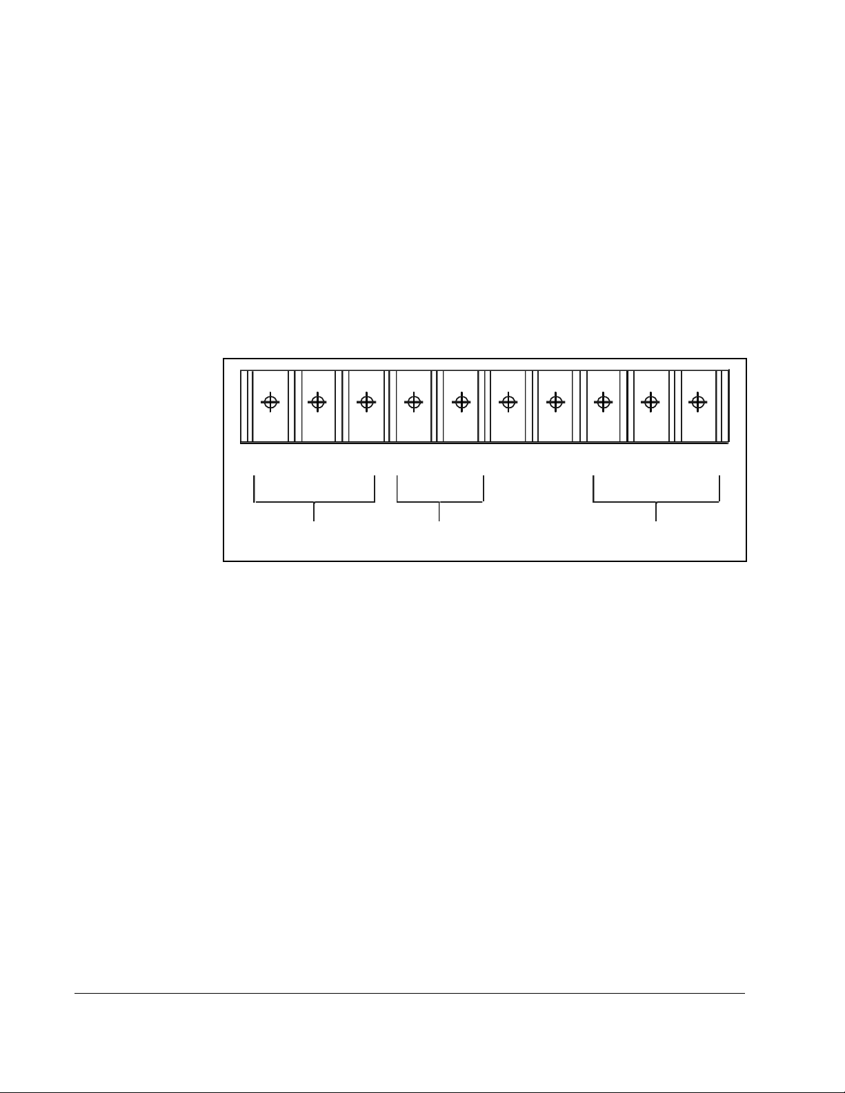
Figure 2.1 – Components of the LonWorks Module .................................................2-1
Figure 3.1 – DC Bus Voltage Terminals (1 to 5HP @ 460VAC) ..............................3-4
Figure 3.2 – LonWorks Module Location in 1 to 5 HP @ 460 VAC Drives..............3-5
Figure 3.3 – DC Bus Voltage Terminals (7.5 to 10 HP @ 460 VAC).......................3-8
Figure 3.4 – LonWorks Module Location in 7.5 to 10 HP Drives..............................3-9
Figure 3.5 – DC Bus Voltage Terminals (1 to 20 HP @ 230 VAC)........................3-12
Figure 3.6 – 1 to 20 HP @ 230 Volt Drive.............................................................3-14
Figure 3.7 – DC Bus Voltage Terminals (30 to 100 HP @ 230 VAC and 75 to 200 HP
@ 460 VAC)....................................................................................... 3-16
Figure 3.8 – Location of Terminal Cover and Regulator Board Cover in 30 to 100 HP
@ 230 VAC and 75 to 200 HP @ 460 VAC Drives ...........................3-17
Figure 3.9 – Regulator Board’s Connection to LonWorks Module, Keypad, and Base
Board..................................................................................................3-19
Figure 3.10 – DC Bus Voltage Terminals (15 to 25 HP @ 460 VAC) ....................3-21
Figure 3.11 – DC Bus Voltage Terminals (25 to 60 HP @ 460 VAC) ....................3-22
Figure 3.12 – LonWorks Module Location in 15 to 25 HP @ 460 VAC Drives.......3-23
Figure 3.13 – LonWorks Module Location in 25 to 60 HP @ 460 VAC Drives.......3-24
Figure 3.14 – LonWorks Module Location in 200 to 400HP @ 460VAC Drives .... 3-27
Figure 6.1 – Location of the Service Pin on the LonWorks Module.......................... 6-1
Figure 7.1 – Node Object..........................................................................................7-1
Figure 7.2 – Drive Object.......................................................................................... 7-2
Figure 9.1 – Status Indicators on the LonWorks Module.......................................... 9-1
Contents
III
Page 6

IV
LonWorks Module for VTAC 7 Drives
Page 7

List of Tables
Table 2.1 – Equipment Shipped with the LonWorks Module....................................2-2
Table 2.2 – Required User-Supplied Equipment ...................................................... 2-2
Table 3.1 – Locating the Appropriate Installation Procedure....................................3-1
Table 3.2 – Model Numbers for 1 to 5 HP@460 VAC Drives.................................. 3-3
Table 3.3 – Model Numbers for 7.5 to 10 HP @ 460 VAC Drives............................3-7
Table 3.4 – Model Numbers for 1 to 20 HP@230 VAC Drives..............................3-11
Table 3.5 – Model Numbers for 30 to100 HP @ 230 VAC and 75 to 200 HP @ 460
VAC Drives .........................................................................................3-15
Table 3.6 – Model Numbers for 15 to 25 HP and 25 to 60 HP @ 460 VAC Drives3-20
Table 3.7 – Model Numbers for 200 to 400 HP @ 460 VAC Drives.......................3-26
Table 4.1 – Terminal Block Terminal Definitionst ..................................................... 4-1
Table 9.1 – Module Status LED: State Definitions....................................................9-2
Table 9.2 – Service LED: State Definitions...............................................................9-2
Table 9.3 – Wink LED: State Definitions...................................................................9-2
Table 9.4 – Communication Module Status LED: State Definitions..........................9-2
Contents
V
Page 8

VI
LonWorks Module for VTAC 7 Drives
Page 9

CHAPTER 1
Introduction
This manual is intended for qualified electrical personnel responsible for installing,
programming, and maintaining AC drives and LonWorks networks. It provides
information about the LonWorks Communication Option Module (2LW3000) and
using it with VTAC 7 drives.
The LonWorks Communication Option module consists of a LonWorks module
mounted on an AnyBus board. It is mounted in the VTAC 7 drive and receives its
required power from the drive and the network.
LonWorks networks consist of intelligent control devices, called nodes, that are
connected by one or more communications media and that communicate with each
other using a common protocol. A LonWorks network can consist of up to 32.385
nodes divided into 255 subnets (127 nodes/subnet).
Nodes on the network can be thought of as objects that respond to various inputs and
produce desired outputs. Linking the inputs and outputs of network objects enables
the network to perform applications. No central control or master-slave architecture is
required.
1.1 Related Documentation
Refer to the following publication as necessary for more information. This publication
is available from http://www.theautomationbookstore.com or
http://www.vtacdrives.com.
• VTAC 7 User's Guide (D2-3372)
1.2 Getting Assistance from Rockwell Automation
If you have any questions or problems with the products described in this instruction
manual, contact your local Rockwell Automation authorized HVAC representative.
For technical assistance, call 1-800-726-8112. Before calling, please the review the
troubleshooting section of this manual and check the VTAC drives website for
additional information. When you call this number, you will be asked for the drive
model number and this instruction manual number.
Introduction
1-1
Page 10

1-2
LonWorks Module for VTAC 7 Drives
Page 11
CHAPTER 2
Getting Started
This chapter provides:
• A description of the LonWorks module’s components
• A list of parts shipped with the module
• A list of user-supplied parts required for installing the module
• An installation checklist
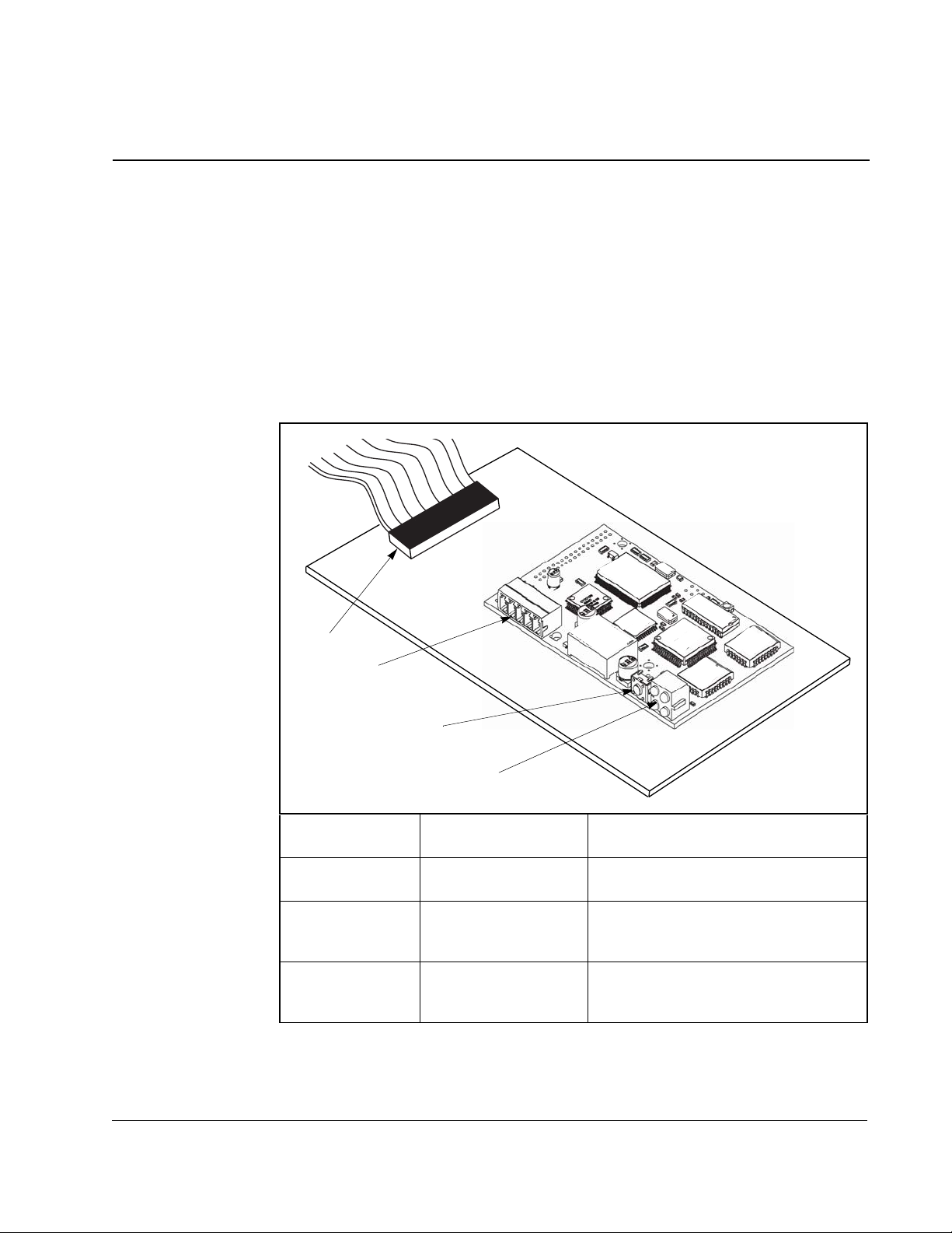
Ribbon Cable
Connector
Terminal Block A 5-screw terminal block connects the
Service Pin A pushbutton identifies the node during
Status Indicators Four LEDs indicate the status of the
Figure 2.1 – Components of the LonWorks Module
Connects the module to the drive.
module to the network.
installation. See chapter 5, Installing
the Drive on the Network.
connected drive, module, and network.
See chapter 7, Troubleshooting.
Getting Started
2-1
Page 12

2.1.Required Equipment
Table 2.1 lists the equipment shipped with the LonWorks module. When you unpack
the module, verify that the package includes all of these items.
Table 2.1 – Equipment Shipped with the LonWorks Module
LonWorks Communications Option module .
LonWorks Communication Option Module User Manual (D2-3498)
Diskette containing .XIF file
Table 2.2 lists user-supplied equipment also required to install and configure the
module.
Table 2.2 – Required User-Supplied Equipment
Phillips screwdriver
Network cable. Recommended cables:
• Belden 851 02, unsh ielded
• Belden 847 1, unsh ie lde d
Item Description
Item Description
• Level IV 22AWG, unshielded
• JY (St) Y 2x2x0.8, shielded
• TIA568A Cat.5 24AWG
For detailed information about recommended cables for a LonWorks network, see
the FTT-10 Free Topology User’s Guide (doc.id.078-0156-01F) at
http://www.echelon.com.
Any standard LonWorks installation tool (for example, LonMaker for Windows).
2-2
LonWorks Module for VTAC 7 Drives
Page 13

2.2 Installation Checklist
This section is designed to help experienced users start using the LonWorks module.
If you are unsure how to complete a step, refer to the referenced chapter
Step Action Refer to
❒
❒
❒
❒
❒
❒
❒
1 Review the safety precautions for the
module.
2 Verify that the drive is properly
installed.
4 Install the module in the drive.
Verify that the drive and the network are
not powered. Then, connect the module
to the drive. Use the captive screws to
secure and ground the module to the
drive.
5 Connect the drive to the network. Chapter 4
6 Apply power to the drive and
network.
Verify that the module and network are
installed correctly and then apply power
to them. The module receives power
from the drive and network.
7 Program the drive for network
communication.
8 Install the drive as a node in the
network.
Use a network tool for LonWorks (such
as LonMaker) to install the drive as a
node in the network.
Throughout
this manual
VTAC 7 AC
Drive User
Manual
(D2-3372)
Chapter 3
Chapter 4
Chapter 5
Instruction
manual for
LonWorks
installation
tool
Getting Started
When to press service pin?
2-3
Page 14

2-4
LonWorks Module for VTAC 7 Drives
Page 15

CHAPTER 3
Installing the LonWorks Module
in the Drive
The LonWorks module installation procedure differs depending on the drive type. Use
table 3.1 to locate the appropriate procedure for your drive.
Table 3.1 – Locating the Appropriate Installation Procedure
Horsepower Rating
1
1
2
2
3
3
5
5
7.5
7.5
10
10
15
15
20
Drive Model Number
1H21xx
1H22xx
1H41xx
1H42xx
2H21xx
2H22xx
2H41xx
2H42xx
3H21xx
3H22xx
3H41xx
3H42xx
5H21xx
5H22xx
5H41xx
5H42xx
7H21xx
7H22xx
7H41xx
7H42xx
10H21xx
10H22xx
10H41xx
10H42xx
15H21xx
15H22xx
15H41xx
15H42xx
20H21xx
20H22xx
Use the Procedure in
Section …
3.3
3.1
3.3
3.1
3.3
3.1
3.3
3.1
3.3
3.2
3.3
3.2
3.3
3.5
3.3
Installing the LonWorks Module in the Drive
3-1
Page 16

Table 3.1 – Locating the Appropriate Installation Procedure (Continued)
Horsepower Rating
20
25
30 30W21xx 3.4
30
40 40W21xx 3.4
40
50 50W21xx 3.4
50
60
60 60W21xx 3.4
75 75W21xx 3.4
75
100 100H21xx 3.4
100
125
150
200 200W41xx 3.4
200 200H41xx 3.6
250 250H41xx 3.6
300 300H41xx 3.6
350 350H41xx 3.6
400 400H41xx 3.6
Drive Model Number
20H41xx
20H42xx
25H41xx
25H42xx
25W21xx
30H41xx
30H42xx
40H41xx
40H42xx
50H41xx
50H42xx
60H41xx
60H42xx
75H41xx
75W41xx
100H41xx
100W41xx
125H41xx
125W41xx
150H41xx
150W41xx
Use the Procedure in
Section …
3.5
3.5
3.5
3.5
3.5
3.5
3.4
3.4
3.4
3.4
3-2
LonWorks Module for VTAC 7 Drives
Page 17

3.1 Installing the Module in 1 to 5 HP@460 VAC Drives
ATTENTION:Only qualified electrical personnel familiar with the
construction and operation of this equipment and the hazards involved
!
should install, adjust, operate, or service this equipment. Read and
understand this manual and other applicable manuals in their entirety
before proceeding. Failure to observe this precaution could result in
severe bodily injury or loss of life.
ATTENTION:The drive is at line voltage when connected to incoming
AC power. Disconnect, lock out, and tag all incoming power to the drive
before performing the following procedure. Failure to observe this
precaution could result in severe bodily injury or loss of life.
ATTENTION:DC bus capacitors retain hazardous voltages after input
power has been disconnected. After disconnecting input power, wait five
minutes for the DC bus capacitors to discharge and then check the
voltage with a voltmeter to ensure the DC bus capacitors are discharged
before touching any internal components. Failure to observe this
precaution could result in severe bodily injury or loss of life.
ATTENTION:The drive contains ESD- (Electrostatic Discharge)
sensitive parts and assemblies. Static control precautions are required
when installing, testing, servicing, or repairing the drive. Erratic machine
operation and damage to, or destruction of, equipment can result if this
procedure is not followed. Failure to observe this precaution can result
in bodily injury.
Use this procedure to install the module in the drives listed in table 3.2.
Table 3.2 – Model Numbers for 1 to 5 HP@460 V AC Drives
VTAC 7 Model Numbers
1H41xx
1H42xx
2H41xx
2H42xx
3H41xx
3H42xx
5H41xx
5H42xx
Refer to figure 3.2 as you perform the procedure.
If the drive is panel-mounted, this procedure will be easier to perform if the drive is
removed from the panel.
Unless otherwise indicated, keep all hardware that is removed. You will need it for
reassembly. This includes screws, lock washers, and rivets.
Important: Read and understand the warning labels on the outside of the drive
before proceeding.
Installing the LonWorks Module in the Drive
3-3
Page 18
Step 1. Shut Down the Drive
Step 1.1 Disconnect, lock out, and tag all incoming power to the drive.
Step 1.2 Wait five minutes for the DC bus capacitors to discharge.
Step 1.3 Remove the cover by loosening the four cover screws.
Important: Read and understand the warning labels on the inside of the drive before
proceeding.
Step 2. Verify That the DC Bus Capacitors are Discharged
Step 2.1 Use a voltmeter to verify that there is no voltage at the drive’s AC input
power terminals (R/L1, S/L2, T/L3).
Step 2.2 Ensure that the DC bus capacitors are discharged. To check
DC bus potential:
a. Stand on a non-conductive surface and wear insulated gloves.
b. Use a voltmeter to measure the DC bus potential at the DC bus power
terminals as shown in figure 3.1.
R/L1 T/L3
S/L2 10V 10 COM
AC Power
Input Leads
Figure 3.1 – DC Bus Voltage Terminals (1 to 5HP @ 460VAC)
+
–+
DC Bus
Volts
Step 3. Remove the Keypad Bracket from the Drive
Step 3.1 Record connections to the Regulator board terminal strip if they must be
disconnected to remove the keypad bracket.
Step 3.2 Use a magnetic screwdriver to remove the three M4 x 10 screws that fasten
the bottom of the keypad support bracket to the drive heat sink.
Important: The keypad support bracket is connected to the drive by wiring. Do not lift
the bracket out completely, because this can damage or pull out wiring.
Step 3.3 S pread the retaining clips on the 26-conductor Regulator board ribbon cable
connector to disconnect it from the Current Feedback board. The Current
Feedback board is located on the right below the keypad.
Step 3.4 Move the keypad support bracket aside.
–
W/T3V/T2U/T1
Motor Leads
3-4
Step 3.5 Pinch the retaining clip that is through the center of the Current Feedback
board and carefully pull out the Current Feedback board.
Step 3.6 Unplug the internal fan assembly power connector (CONN7) from the drive.
LonWorks Module for VTAC 7 Drives
Page 19
Step 4. Install the LonW orks Module in the Keypad Bracket
ATTENTION:The drive contains ESD- (Electrostatic Discharge)
sensitive parts and assemblies. Static control precautions are required
!
when installing, testing, servicing, or repairing the drive. Erratic machine
operation and damage to, or destruction of, equipment can result if this
procedure is not followed. Failure to observe this precaution can result
in bodily injury.
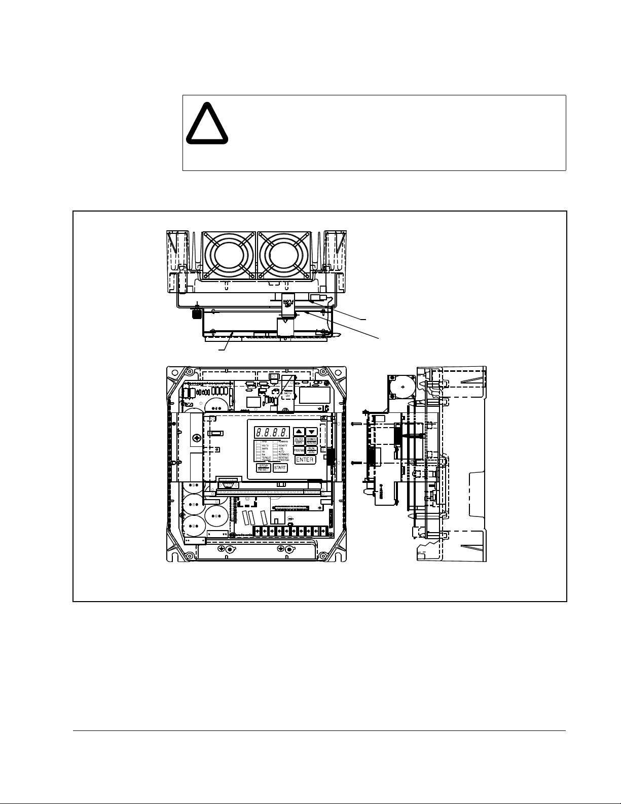
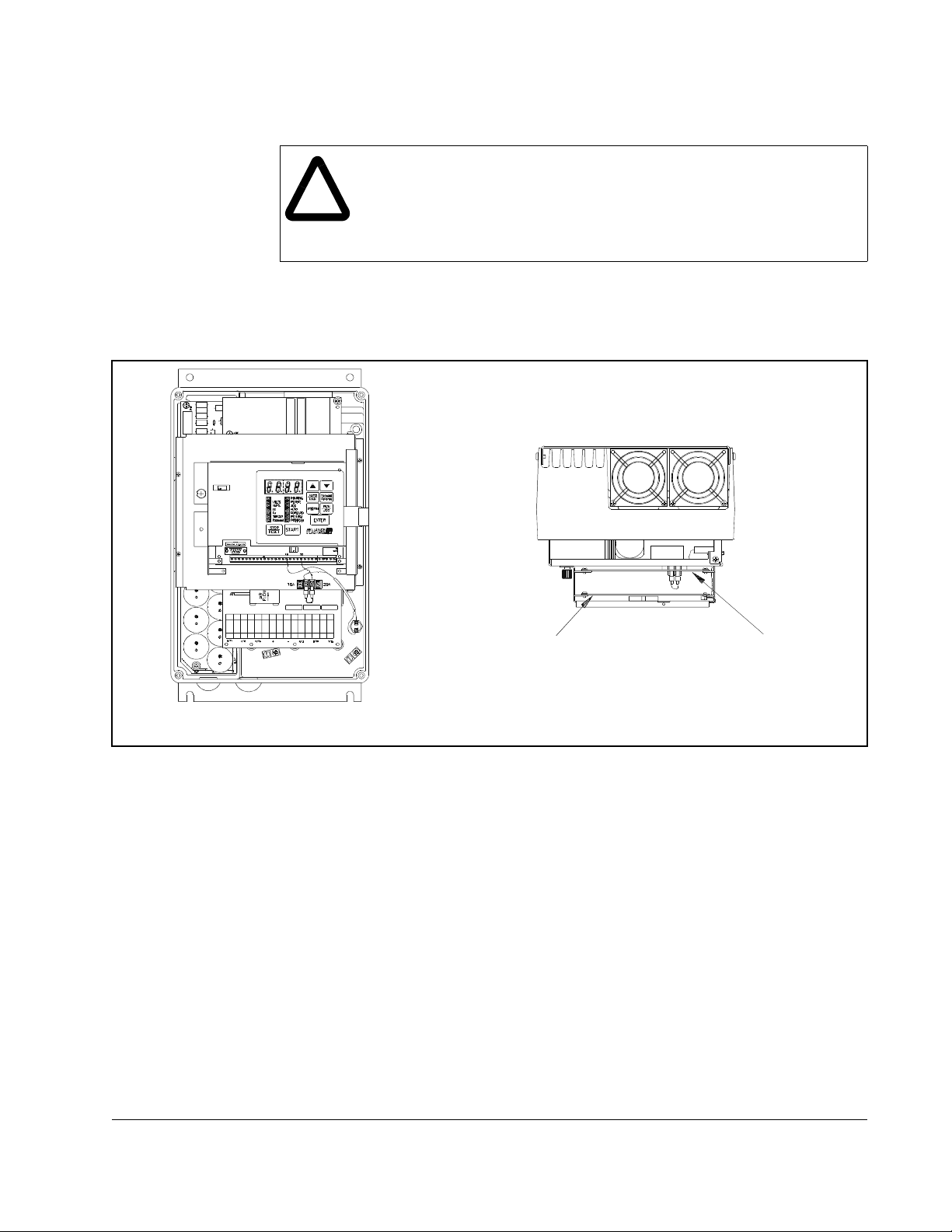
Refer to figure 3.2 for component locations.
LonWorks
Module
Regulator
Board
LonWorks
Module
Top View
Current Feedback
Board
AUTO
STAR T
RUNNING
REMOTE
JOGAMPS
AUTO
FORWARD
REVERSE
PROGRAMPROGRAM
20
ENTER
Forward
Reverse
RUN
JOG
Side View
RPM
VOLTS
Hz
Kw
TORQUE
Password
STOP
RESET
16
Front View
Figure 3.2 – LonWorks Module Location in 1 to 5 HP @ 460 VAC Drives
Step 4.1 Remove the LonWorks module from its anti-static wrapper. Align the key on
the Regulator board’s 34-conductor ribbon cable connector with the slot in
the LonWorks module’s connector. Press the ribbon cable connector in until
it locks into position.
Step 4.2 Route the 26-conductor ribbon cable for the Current Feedback board out of
Step 4.3 Align the LonWorks module on the four mounting tabs on the keypad
Installing the LonWorks Module in the Drive
the side of the keypad bracket.
bracket. Make sure that the ribbon cable is not pinched between the keypad
bracket and the LonWorks module.
3-5
Page 20
Step 4.4 Fasten the LonWorks module to the right side of the keypad bracket using
the two metal M3 screws and lock washers for proper grounding. Fasten the
left side using the two 6-32 screws and lock washers for proper grounding.
Important:
Step 5. Reinstall the Keypad Bracket in the Drive
Step 5.1 Reconnect the internal fan assembly power connector (CONN7) to the
!
Step 5.2 Reinstall the Current Feedback board. Carefully align the two sets of
Step 5.3 Inspect the Current Feedback board connector thoroughly for bent or
Step 5.4 Align the keypad support bracket with the mounting holes in the drive heat
You must use the lock washers to properly ground the LonWorks module.
Improper grounding of the LonWorks module can result in erratic operation
of the drive.
drive. Align the key on the connector with the slot in the receptacle. Press
the connector into position.
ATTENTION:Proper alignment of the Current Feedback board is critical.
Verify that the connector pins on the Current Feedback board are
correctly aligned with their corresponding connectors on the drive.
Failure to observe this precaution can result in bodily injury.
connector pins on the Current Feedback board with their matching
connectors on the drive. Gently press the board into place. The board
should go in easily. If you feel resistance, a pin might be bent or misaligned.
Recheck alignment and retry installation.
misaligned pins.
sink. Fasten the bracket with the three M4 x 10 screws removed earlier.
Step 5.5 Align the Regulator board’s 26-conductor ribbon cable connector with the
Current Feedback board connector. Press it in until it locks into position.
Step 5.6 Reconnect any wiring that was removed from the Regulator board terminal
strip. Refer to the terminal connections documented in step 3.1 or to the
appropriate instruction manuals for the devices being used.
Step 5.7 NEMA 4X/12 drives only: Before installing the cover , check that the gaskets
on the cover are flat and within the gasket channels.
Step 5.8 Reinstall the cover. Align all cover screws into the heat sink before
tightening any of them.
To maintain the integrity of NEMA 4X/12 drives, sequentially tighten the
cover screws to ensure even compression of the gaskets. Do not exceed
2.2 Nm (20 in-lb) of torque on these screws.
3-6
LonWorks Module for VTAC 7 Drives
Page 21

3.2 Installing the LonWorks Module in
7.5 to 10 HP @ 460 VAC Drives
ATTENTION:Only qualified electrical personnel familiar with the
construction and operation of this equipment and the hazards involved
!
should install, adjust, operate, or service this equipment. Read and
understand this manual and other applicable manuals in their entirety
before proceeding. Failure to observe this precaution could result in
severe bodily injury or loss of life.
ATTENTION:The drive is at line voltage when connected to incoming
AC power. Disconnect, lock out, and tag all incoming power to the drive
before performing the following procedure. Failure to observe this
precaution could result in severe bodily injury or loss of life.
ATTENTION:DC bus capacitors retain hazardous voltages after input
power has been disconnected. After disconnecting input power, wait five
minutes for the DC bus capacitors to discharge and then check the
voltage with a voltmeter to ensure the DC bus capacitors are discharged
before touching any internal components. Failure to observe this
precaution could result in severe bodily injury or loss of life.
ATTENTION:The drive contains ESD- (Electrostatic Discharge)
sensitive parts and assemblies. Static control precautions are required
when installing, testing, servicing, or repairing the drive. Erratic machine
operation and damage to, or destruction of, equipment can result if this
procedure is not followed. Failure to observe this precaution can result
in bodily injury.
Use this procedure to install the LonWorks module in the drives listed in table 3.3.
Table 3.3 – Model Numbers for 7.5 to 10 HP @ 460 VAC Drives
Refer to figure 3.4 as you perform this procedure.
If the drive is panel-mounted, this procedure will be easier to perform if the drive is
removed from the panel.
Unless otherwise indicated, keep all hardware that is removed. You will need it for
reassembly. This includes screws, lock washers, and rivets.
Important: Read and understand the warning labels on the outside of the drive
before proceeding.
Step 1. Shut Down the Drive
Step 1.1 Disconnect, lock out, and tag all incoming power to the drive.
Step 1.2 Wait five minutes for the DC bus capacitors to discharge.
VTAC 7 Model Numbers
7H41xx
7H42xx
10H41xx
10H42xx
Installing the LonWorks Module in the Drive
3-7
Page 22
Step 1.3 Remove the cover by loosening the four cover screws.
Important: Read and understand the warning labels on the inside of the drive before
proceeding.
Step 2. Verify That the DC Bus Capacitors are Discharged
Step 2.1 Use a voltmeter to verify that there is no voltage at the drive’s AC input
power terminals (R/L1, S/L2, T/L3).
Step 2.2 Ensure that the DC bus capacitors are discharged. To check
DC bus potential:
a. Stand on a non-conductive surface and wear insulated gloves.
b. Use a voltmeter to measure the DC bus potential at the DC bus power
terminals shown in figure 3.3.
R/L1 T/L3
S/L2 10V 10 COM
AC Power
Input Leads
Figure 3.3 – DC Bus Voltage Terminals (7.5 to 10 HP @ 460 VAC)
+
–+
DC Bus
Volts
Step 3. Remove the Keypad Bracket from the Drive
Step 3.1 Record connections to the Regulator board terminal strip if they must be
disconnected to remove the keypad bracket.
Step 3.2 Loosen the thumb screw on the left side of the keypad bracket. Hold the
bracket on the left and lift the bracket up and to the left to separate it from
the keypad support bracket.
Important: The keypad support bracket is connected to the drive by wiring. Do not lift
the bracket out completely, because this can damage or pull out wiring.
Tie up or support the bracket to prevent damage to the wiring.
Step 3.3 S pread the retaining clips on the 26-conductor Regulator board ribbon cable
connector to disconnect it from the Current Feedback board. The Current
Feedback board is located on the right below the keypad.
–
W/T3V/T2U/T1
Motor Leads
3-8
LonWorks Module for VTAC 7 Drives
Page 23
Step 4. Install the LonW orks Module in the Keypad Bracket
ATTENTION:The drive contains ESD- (Electrostatic Discharge)
sensitive parts and assemblies. Static control precautions are required
!
Refer to figure 3.4 for component locations.
Regulator Board
when installing, testing, servicing, or repairing the drive. Erratic machine
operation and damage to, or destruction of, equipment can result if this
procedure is not followed. Failure to observe this precaution can result
in bodily injury.
Current Feedback Board
LonWorks Module
LonWorks Module
Top View
Figure 3.4 – LonWorks Module Location in 7.5 to 10 HP Drives
Step 4.1 Remove the LonWorks module from its anti-static wrapper. Align the key on
Step 4.2 Route the 26-conductor ribbon cable for the Current Feedback board out of
Installing the LonWorks Module in the Drive
Front View
the Regulator board’s 34-conductor ribbon cable connector with the slot in
the LonWorks module’s connector. Press the ribbon cable connector in until
it locks into position.
the side of the keypad bracket.
Side View
3-9
Page 24

Step 4.3 Align the LonWorks module on the four mounting tabs on the keypad
bracket. Make sure that the ribbon cable is not pinched between the keypad
bracket and the LonWorks module.
Step 4.4 Fasten the LonWorks module to the right side of the keypad bracket using
the two metal M3 screws and lock washers for proper grounding. Fasten the
left side using the two 6-32 screws and lock washers for proper grounding.
Important: Y ou must use the lock washers to properly ground the LonWorks module.
Improper grounding of the LonWorks module can result in erratic
operation of the drive.
Step 4.5 Reconnect the keypad bracket to the keypad support bracket by inserting
the mounting tabs into the slots in the keypad support bracket and tightening
the thumb screw.
Step 4.6 Align the Regulator board’s 26-conductor ribbon cable connector with the
Current Feedback board connector. Press it in until it locks into position.
Step 5. Reassemble the Drive
Step 5.1 Reconnect any wiring that was removed from the Regulator board terminal
strip. Refer to the terminal connections documented in step 3.1 or to the
appropriate instruction manuals for the devices being used.
Step 5.2 NEMA 4X/12 drives only: Before installing the cover , check that the gaskets
on the cover are flat and within the gasket channels.
Step 5.3 Reinstall the cover. Align all cover screws into the heat sink before
tightening any of them.
To maintain the integrity of NEMA 4X/12 drives, sequentially tighten the
cover screws to ensure even compression of the gaskets. Do not exceed
2.2 Nm (20 in-lb) of torque on these screws.
3-10
LonWorks Module for VTAC 7 Drives
Page 25
3.3 Installing the LonWorks Module in
1to20HP@230VAC Drives
ATTENTION:Only qualified electrical personnel familiar with the
construction and operation of this equipment and the hazards involved
!
should install, adjust, operate, or service this equipment. Read and
understand this manual and other applicable manuals in their entirety
before proceeding. Failure to observe this precaution could result in
severe bodily injury or loss of life.
ATTENTION:The drive is at line voltage when connected to incoming
AC power. Disconnect, lock out, and tag all incoming power to the drive
before performing the following procedure. Failure to observe this
precaution could result in severe bodily injury or loss of life.
ATTENTION:DC bus capacitors retain hazardous voltages after input
power has been disconnected. After disconnecting input power, wait five
minutes for the DC bus capacitors to discharge and then check the
voltage with a voltmeter to ensure the DC bus capacitors are discharged
before touching any internal components. Failure to observe this
precaution could result in severe bodily injury or loss of life.
ATTENTION:The drive contains ESD- (Electrostatic Discharge)
sensitive parts and assemblies. Static control precautions are required
when installing, testing, servicing, or repairing the drive. Erratic machine
operation and damage to, or destruction of, equipment can result if this
procedure is not followed. Failure to observe this precaution can result
in bodily injury.
Use this procedure to install the LonWorks module in the drives listed in table 3.4.
Table 3.4 – Model Numbers for 1 to 20 HP@230 VAC Drives
VTAC 7 Model Numbers
1H21xx
1H22xx
2H21xx
2H22xx
3H21xx
3H22xx
5H21xx
5H22xx
7H21xx
7H22xx
10H21xx
10H22xx
15H21xx
15H22xx
20H21xx
20H22xx
Refer to figure 3.6 as you perform this procedure.
Installing the LonWorks Module in the Drive
3-11
Page 26

If the drive is panel-mounted, this procedure will be easier to perform if the drive is
removed from the panel.
Unless otherwise indicated, keep all hardware that is removed. You will need it for
reassembly. This includes screws, lock washers, and rivets.
Important: Read and understand the warning labels on the outside of the drive
before proceeding.
Step 1. Shut Down the Drive
Step 1.1 Disconnect, lock out, and tag all incoming power to the drive.
Step 1.2 Wait five minutes for the DC bus capacitors to discharge.
Step 1.3 Remove the cover by loosening the four cover screws.
Important: Read and understand the warning labels on the inside of the drive before
proceeding.
Step 2. Verify That the DC Bus Capacitors are Discharged
Step 2.1 Use a voltmeter to verify that there is no voltage at the drive’s AC input
power terminals (R/L1, S/L2, T/L3).
Step 2.2 Ensure that the DC bus capacitors are discharged. To check
DC bus potential:
a. Stand on a non-conductive surface and wear insulated gloves.
b. Use a voltmeter to measure the DC bus potential at the DC bus power
terminals shown in figure 3.5.
+
R/L1 T/L3
Step 3. Remove the Keypad Bracket from the Drive
Step 3.1 Record connections to the Regulator board terminal strip if they must be
disconnected to remove the keypad bracket.
S/L2
AC Power
Input Leads
Figure 3.5 – DC Bus Voltage Terminals (1 to 20 HP @ 230 VAC)
DC Bus
Volts
–
W/T3V/T2U/T1
Motor Leads
3-12
Step 3.2 Use a magnetic screwdriver to remove the M4 x 10 screws that fasten the
bottom of the keypad support bracket to the drive.
LonWorks Module for VTAC 7 Drives
Page 27

Step 3.3 Spread the retaining clips on the Regulator board ribbon cable (on the right
side) to disconnect it from the Base Board.
Step 3.4 Remove the keypad bracket. Place it with the keypad down on a flat surface.
If you cannot lay it flat, tie it up to prevent damage to wiring.
Step 4. Install the LonW orks Module in the Keypad Bracket
Refer to figure 3.6 for component locations.
Step 4.1 Remove the LonWorks module from its anti-static wrapper. Align the key on
the Regulator board’s 34-conductor ribbon cable connector with the slot in
the LonWorks module’s connector. Press the ribbon cable connector in until
it locks into position.
Step 4.2 Route the other ribbon cable out of the side of the keypad bracket.
Step 4.3 Align the LonWorks module on the four mounting tabs on the keypad
bracket. Make sure that the ribbon cable is not pinched between the keypad
bracket and the LonWorks module.
Step 4.4 Fasten the LonWorks module to the right side of the keypad bracket using
the two metal M3 screws and lock washers for proper grounding. Fasten the
left side using the two 6-32 screws and lock washers for proper grounding.
Important: Y ou must use the lock washers to properly ground the LonWorks module.
Improper grounding of the LonWorks module can result in erratic
operation of the drive.
Step 5. Reinstall the Keypad Bracket in the Drive
Step 5.1 Place the keypad support bracket back into position. Use a magnetic
screwdriver to fasten it to the drive with the screws removed in step 3.2.
Step 5.2 Realign the 26-conductor ribbon cable connector with the connector inside
the slot in the keypad support bracket. Carefully press the ribbon cable
connector in until the retaining clips lock into place.
Step 5.3 Reconnect any wiring that was removed from the Regulator board terminal
strip. Refer to the terminal connections documented in step 3.1 or to the
appropriate instruction manuals for the devices being used.
Step 5.4 NEMA 4X/12 drives only: Before installing the cover , check that the gaskets
on the cover are flat and within the gasket channels.
Installing the LonWorks Module in the Drive
3-13
Page 28

Keypad Bracket
Regulator Board
Terminal Strip
Power Term inal
Strip
Figure 3.6 – 1 to 20 HP @ 230 Volt Drive
Step 5.5 Reinstall the cover. Align all cover screws into the heat sink before
tightening any of them.
To maintain the integrity of NEMA 4X/12 drives, sequentially tighten the
cover screws to ensure even compression of the gaskets. Do not exceed
2.2 Nm (20 in-lb) of torque on these screws.
3-14
LonWorks Module for VTAC 7 Drives
Page 29

3.4 Installing the LonWorks Module in
30 to 100HP@230 VAC and 75 to 200 @ 460VAC
Drives
ATTENTION:Only qualified electrical personnel familiar with the
construction and operation of this equipment and the hazards involved
!
should install, adjust, operate, or service this equipment. Read and
understand this manual and other applicable manuals in their entirety
before proceeding. Failure to observe this precaution could result in
severe bodily injury or loss of life.
ATTENTION:The drive is at line voltage when connected to incoming
AC power. Disconnect, lock out, and tag all incoming power to the drive
before performing the following procedure. Failure to observe this
precaution could result in severe bodily injury or loss of life.
ATTENTION:DC bus capacitors retain hazardous voltages after input
power has been disconnected. After disconnecting input power, wait five
minutes for the DC bus capacitors to discharge and then check the
voltage with a voltmeter to ensure the DC bus capacitors are discharged
before touching any internal components. Failure to observe this
precaution could result in severe bodily injury or loss of life.
ATTENTION:The drive contains ESD- (Electrostatic Discharge)
sensitive parts and assemblies. Static control precautions are required
when installing, testing, servicing, or repairing the drive. Erratic machine
operation and damage to, or destruction of, equipment can result if this
procedure is not followed. Failure to observe this precaution can result
in bodily injury.
Use this procedure to install the LonWorks module in the drives listed in table 3.5.
Table 3.5 – Model Numbers for 30 to100 HP @ 230 VAC and 75 to 200 HP @ 460 VAC Drives
VTAC 7 Model Numbers
30 to 100HP @
230VAC
30W21xx
50W21xx
60W21xx
75W21xx
100H21xx
Refer to figures 3.8 and 3.9 as you perform the procedure.
Unless otherwise indicated, keep all hardware that is removed. You will need it for
reassembly. This includes screws, lock washers, and rivets.
Important: Read and understand the warning labels on the outside of the drive
before proceeding.
75 to 200HP @
460VAC
75H41xx
75W41xx
100H41xx
100W41xx
125H41xx
125W41xx
150H41xx
150W41xx
200W41xx
Installing the LonWorks Module in the Drive
3-15
Page 30

Step 1. Shut Down the Drive
Step 1.1Disconnect, lock out, and tag all incoming power to the drive.
Step 1.2 Wait five minutes for the DC bus capacitors to discharge.
Step 1.3 Open the drive’s outer cabinet door.
Step 1.1 Read and understand the warning labels on the inside of the drive before
proceeding.
Step 2. Verify That the DC Bus Capacitors are Discharged
Step 2.1 Use a voltmeter to verify that there is no voltage at the drive’s AC input
power terminals (R/L1, S/L2, T/L3 or U/T1, V/T2, W/T3).
Step 2.2 Ensure that the DC bus capacitors are discharged. To check
DC bus potential:
a. Stand on a non-conductive surface and wear insulated gloves.
b. Use a voltmeter to measure the DC bus potential at the DC bus power
terminals shown in figure 3.7.
DC Bus
P (+)
R
S
Volts
T
N (-)
3-16
U (T1)
W (T3)
Figure 3.7 – DC Bus Voltage Terminals (30 to 100 HP @ 230 VAC and 75 to 200 HP @ 460 VAC)
GND
V (T2)
LonWorks Module for VTAC 7 Drives
Page 31

Step 3. Remove the Keypad Bracket from the Drive
Step 3.1 Remove the Power Module from the drive cabinet.
Step 3.2 If the drive has:
•
A Regulator bo ard and te rminal co ver: Re move the th ree M4 sc rews from the
cover plate over the Regulator board. Remove the cover. See figure 3.8.
•
A terminal cover only: If you have this type of drive, this procedure is easier
to perform if you lay the drive on its side. Remove the side cover from the
drive. Use a long magnetized screwdriver to unfasten the four screws that
hold the keyp ad bracket in.
Step 3.3 Remove the terminal cover, which is below the keypad and fastened with
two M4 screws. See figure 3.8.
Figure 3.8 – Location of Terminal Cover and Regulator Board Cover in 30 to 100 HP @ 230 VAC and 75 to 200 HP @ 460 VAC Drives
Step 3.4 Record connections to the Regulator board terminal strip if they must be
disconnected to remove the keypad bracket.
Step 3.5 Remove the anodized inner cover by removing the two M3 roundhead
screws.
Step 3.6 Pull the keypad assembly partly out of the drive. Spread the retaining clips
on the Regulator board ribbon cable (on the right side) to disconnect it from
the Base Board. See figure 3.9.
Step 3.7 Remove the keypad bracket. Place it with the keypad down on a flat surface.
If you cannot lay it flat, tie it up to prevent damage to wiring.
Installing the LonWorks Module in the Drive
3-17
Page 32

Step 4. Install the LonW orks Module in the Keypad Bracket
ATTENTION:The drive contains ESD- (Electrostatic Discharge)
sensitive parts and assemblies. Static control precautions are required
!
Refer to figures 3.8 and 3.9 for component locations.
Step 4.1 Remove the LonWorks module from its anti-static wrapper. Align the key on
Step 4.2 Route the other ribbon cable out of the side of the keypad support bracket.
Step 4.3 Align the LonWorks module on the four mounting tabs on the keypad
Step 4.4 Fasten the LonWorks module to the right side of the keypad bracket using
when installing, testing, servicing, or repairing the drive. Erratic machine
operation and damage to, or destruction of, equipment can result if this
procedure is not followed. Failure to observe this precaution can result
in bodily injury.
the Regulator board’s 34-conductor ribbon cable connector with the slot in
the LonWorks module’s connector. Press the ribbon cable connector in until
it locks into position.
bracket. Make sure that the ribbon cable is not pinched between the keypad
bracket and the LonWorks module.
the two metal M3 screws and lock washers for proper grounding. Fasten the
left side using the two 6-32 screws and lock washers for proper grounding.
Important:
Step 5. Reinstall the Keypad Bracket in the Drive
Step 5.1 Align the Regulator board ribbon cable connector with the connector to the
Step 5.2 Place the keypad bracket back into position.
Step 5.3 Reattach the anodized inner cover.
Step 5.4 If the drive has:
Step 5.5 Reconnect any wiring that was removed from the Regulator board terminal
You must use the lock washers to properly ground the LonWorks module.
Improper grounding of the LonWorks module can result in erratic operation
of the drive.
Base board. Carefully press the ribbon cable connector in until the retaining
clips lock into place.
•
A Regulator board cover and a terminal cover: Replace the Regulator board
cover. Fasten it using the three M4 screws removed in earlier.
•
Only a terminal cover: Use a long magnetized screwdriver to fasten the four
screws that hold the keypad bracket. Replace the side cover.
strip. Refer to the terminal connections documented in step 3.4 or to the
appropriate instruction manuals for the devices being used.
3-18
LonWorks Module for VTAC 7 Drives
Page 33
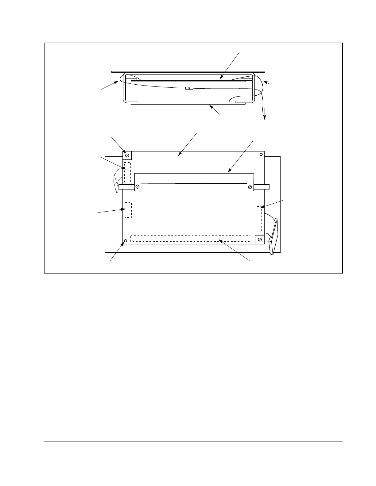
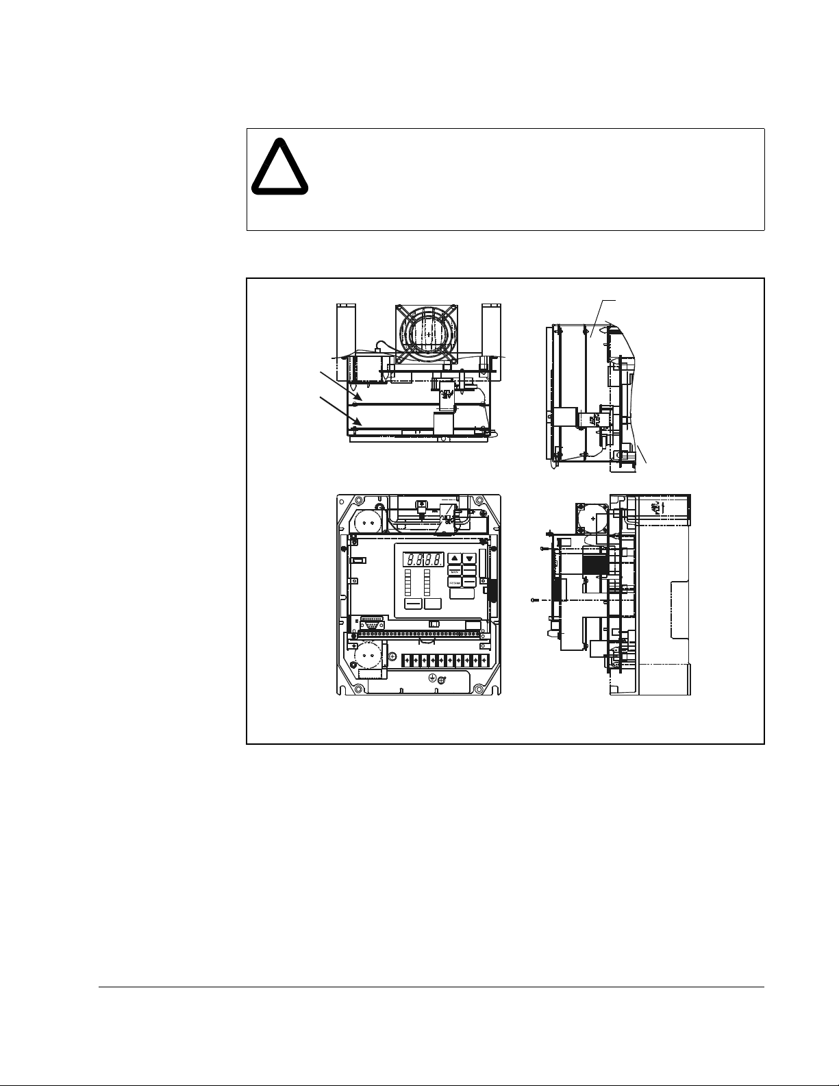
Ribbon Cable
Connecting
Regulator Board and
Base Board
Front
Top View
Regulator Board
LonWorks
Ribbon Cable
Connecting
Regulator Board
and LonWorks
Module
To Base Board
Metal Screw
Ribbon Cable
Connector to
Connect Base
Board
Ribbon Cable
Connector to
Connect Keypad
Plastic Rivet
Figure 3.9 – Regulator Board’s Connection to LonWorks Module, Keypad, and Base Board
Back Side of
Regulator Board
Insulator
Ribbon Cable
Connector to
Connect
LonWorks
Module
Rear View of Regulator Board
Terminal Strip
Step 5.6 Replace the terminal cover (below the keypad). Fasten it using the M4
screws removed earlier.
Step 5.7 Reinstall the Power Module in the drive cabinet.
Step 5.8 Close the outer cabinet door.
Installing the LonWorks Module in the Drive
3-19
Page 34

3.5 Installing the LonWorks Module in 15 to 25 HP and
25 to 60 HP @ 460VAC Drives
ATTENTION:Only qualified electrical personnel familiar with the
construction and operation of this equipment and the hazards involved
!
should install, adjust, operate, or service this equipment. Read and
understand this manual and other applicable manuals in their entirety
before proceeding. Failure to observe this precaution could result in
severe bodily injury or loss of life.
ATTENTION:The drive is at line voltage when connected to incoming
AC power. Disconnect, lock out, and tag all incoming power to the drive
before performing the following procedure. Failure to observe this
precaution could result in severe bodily injury or loss of life.
ATTENTION:DC bus capacitors retain hazardous voltages after input
power has been disconnected. After disconnecting input power, wait five
minutes for the DC bus capacitors to discharge and then check the
voltage with a voltmeter to ensure the DC bus capacitors are discharged
before touching any internal components. Failure to observe this
precaution could result in severe bodily injury or loss of life.
ATTENTION:The drive contains ESD- (Electrostatic Discharge)
sensitive parts and assemblies. Static control precautions are required
when installing, testing, servicing, or repairing the drive. Erratic machine
operation and damage to, or destruction of, equipment can result if this
procedure is not followed. Failure to observe this precaution can result
in bodily injury.
Use this procedure to install the LonWorks module in the drives listed in table 3.6.
Table 3.6 – Model Numbers for 15 to 25 HP and 25 to60 HP @ 460 VAC Drives
Model Numbers for 15 to 25 HP
VTAC 7 Drives
15H41xx
15H42xx
20H41xx
20H42xx
25H41xx
25H42xx
Refer to figure 3.12 or 3.13 as you perform the procedure.
Unless otherwise indicated, keep all hardware that is removed. You will need it for
reassembly. This includes screws, lock washers, and rivets.
If the drive is panel-mounted, this procedure will be easier to perform if the drive is
removed from the panel.
Model Numbers for 25 to 60 HP
VTAC 7 Drives
25W21xx
30H41xx
30H42xx
40H41xx
40H42xx
50H41xx
50H42xx
60H41xx
60H42xx
3-20
LonWorks Module for VTAC 7 Drives
Page 35

Important: Read and understand the warning labels on the outside of the drive
before proceeding.
Step 1. Shut Down the Drive
Step 1.1 Disconnect, lock out, and tag all incoming power to the drive.
Step 1.2 Wait five minutes for the DC bus capacitors to discharge.
Step 1.3 Remove the cover by loosening the four cover screws.
Important: Read and understand the warning labels on the inside of the drive before
proceeding.
Step 2. Verify That the DC Bus Capacitors are Discharged
Step 2.1 Use a voltmeter to verify that there is no voltage at the drive’s AC input
power terminals (R/L1, S/L2, T/L3).
Step 2.2 Ensure that the DC bus capacitors are discharged. To check
DC bus potential:
a. Stand on a non-conductive surface and wear insulated gloves.
b. Use a voltmeter to measure the DC bus potential at the DC bus power
terminals as shown in figures 3.10 (15 to 25 HP @ 460 volts) and 3.11
(25 to 60 HP @ 460 volts).
U/T1 T/L3
Installing the LonWorks Module in the Drive
V/T2
Motor Leads
Figure 3.10 – DC Bus Voltage Terminals (15 to 25 HP @ 460 VAC)
+
DC Bus
Volts
–
R/L1W/T3
S/L2
AC Power
Input Leads
3-21
Page 36

Figure 3.11 – DC Bus Voltage Terminals (25 to 60 HP @ 460 VAC)
Step 3. Remove the Keypad Bracket from the Drive
See figure 3.12 (15 to 25 HP @ 460 VAC) or 3.13 (25 to 60 HP @ 460 VAC) for part
locations.
Step 3.1 Record connections to the Regulator board terminal strip if they must be
disconnected to remove the keypad bracket.
Input WiringDC Bus Volts
Step 3.2 Loosen the thumb screw on the left side of the keypad bracket. Hold the
bracket on the left and lift the bracket up and to the left to separate it from
the keypad support bracket.
Important: The keypad support bracket is connected to the drive by wiring. Do not lift
the bracket out completely, because this can damage or pull out wiring.
Tie up or support the bracket to prevent damage to the wiring.
Step 3.3 Disconnect the 26-conductor Regulator board ribbon cable from the Power
Supply board (located on the right side below the keypad). You can see the
connector through the slot on the keypad support bracket. Use a small
screwdriver inserted through the slot to spread the retaining clips on the
connector to release it.
3-22
LonWorks Module for VTAC 7 Drives
Page 37
Step 4. Install the LonW orks Module in the Keypad Bracket
ATTENTION:The drive contains ESD- (Electrostatic Discharge)
sensitive parts and assemblies. Static control precautions are required
!
Step 4.1 Remove the LonWorks module from its anti-static wrapper. Align the key on
when installing, testing, servicing, or repairing the drive. Erratic machine
operation and damage to, or destruction of, equipment can result if this
procedure is not followed. Failure to observe this precaution can result
in bodily injury.
the Regulator board’s 34-conductor ribbon cable connector with the slot in
the LonWorks module’s connector. Press the ribbon cable connector in until
it locks into position.
Regulator Board
Top ViewFront View
Figure 3.12 – LonWorks Module Location in 15 to 25 HP @ 460 VAC Drives
LonWorks
Module
Installing the LonWorks Module in the Drive
3-23
Page 38

Regulator Board
LonWorks
Module
Front View
Figure 3.13 – LonWorks Module Location in 25 to 60 HP @ 460 VAC Drives
Step 4.2 Align the LonWorks module on the four mounting tabs on the keypad
bracket. Make sure that the ribbon cable is not pinched between the keypad
bracket and the LonWorks module.
Step 4.3 Fasten the LonWorks module to the right side of the keypad bracket using
the two metal M3 screws and lock washers for proper grounding. Fasten the
left side using the two 6-32 screws and lock washers for proper grounding.
Important:
You must use the lock washers to properly ground the LonWorks module.
Improper grounding of the LonWorks module can result in erratic operation
of the drive.
Step 4.4 Realign the 26-conductor ribbon cable connector with the Power Supply
board connector inside the slot in the keypad support bracket. Carefully
press the ribbon cable connector in until the retaining clips lock it into place.
Step 5. Reinstall the Keypad Bracket in the Drive
Step 5.1 Reconnect the keypad bracket to the keypad support bracket by inserting
the mounting tabs into the slots in the keypad support bracket and tightening
the thumb screw.
Step 5.2 Reconnect any wiring that was removed from the Regulator board terminal
strip. Refer to the terminal connections documented in step 3.1 or to the
appropriate instruction manuals for the devices being used.
Top View
3-24
Step 5.3 NEMA 4X/12 drives only: Before installing the cover , check that the gaskets
on the cover are flat and within the gasket channels.
Step 5.4 Reinstall the cover. Align all cover screws into the heat sink before
tightening any of them.
LonWorks Module for VTAC 7 Drives
Page 39

To maintain the integrity of NEMA 4X/12 drives, sequentially tighten the
cover screws to ensure even compression of the gaskets. Do not exceed
2.2 Nm (20 in-lb) of torque on these screws.
Installing the LonWorks Module in the Drive
3-25
Page 40

3.6 Installing the LonWorks Module in 200 to 400 HP @
460 VAC Drives
ATTENTION:Only qualified electrical personnel familiar with the
construction and operation of this equipment and the hazards involved
!
should install, adjust, operate, or service this equipment. Read and
understand this manual and other applicable manuals in their entirety
before proceeding. Failure to observe this precaution could result in
severe bodily injury or loss of life.
ATTENTION:The drive is at line voltage when connected to incoming
AC power. Disconnect, lock out, and tag all incoming power to the drive
before performing the following procedure. Failure to observe this
precaution could result in severe bodily injury or loss of life.
ATTENTION:DC bus capacitors retain hazardous voltages after input
power has been disconnected. After disconnecting input power, wait five
minutes for the DC bus capacitors to discharge and then check the
voltage with a voltmeter to ensure the DC bus capacitors are discharged
before touching any internal components. Failure to observe this
precaution could result in severe bodily injury or loss of life.
ATTENTION:The drive contains ESD- (Electrostatic Discharge)
sensitive parts and assemblies. Static control precautions are required
when installing, testing, servicing, or repairing the drive. Erratic machine
operation and damage to, or destruction of, equipment can result if this
procedure is not followed. Failure to observe this precaution can result
in bodily injury.
Use this procedure to install the LonWorks module in the drives listed in table 3.7.
Table 3.7 – Model Numbers for 200 to 400 HP @ 460 VAC Drives
Refer to figure 3.14 as you peform the procedure.
Unless otherwise indicated, keep all hardware that is removed. You will need it for
reassembly. This includes screws, lock washers, and rivets.
Important: Read and understand the warning labels on the outside of the drive
before proceeding.
Step 1. Shut Down the Drive
Step 1.1 Disconnect, lock out, and tag all incoming power to the drive.
Step 1.2 Wait five minutes for the DC bus capacitors to discharge.
Important: Read and understand the warning labels on the inside of the drive before
proceeding.
VTAC 7 Model Numbers
200H41xx
250H41xx
300H41xx
350H41xx
400H41xx
3-26
LonWorks Module for VTAC 7 Drives
Page 41
Step 2. Verify That the DC Bus Capacitors are Discharged
Step 2.1 Open the drive’s outer cabinet door.
Step 2.2 Lower the plastic terminal strip shield at the top of the drive.
Step 2.3 Use a voltmeter to verify that there is no voltage at the drive’s AC input
power terminals, R, S, and T.
Step 2.4 Replace the plastic terminal strip shield.
Step 2.5 Ensure that the DC bus capacitors are discharged. To check
DC bus potential:
a. Stand on a non-conductive surface and wear insulated gloves. (600 V)
b. Use a voltmeter to check the DC bus potential at the Voltmeter Test
Points on the Power Module Interface board. See figure 3.14.
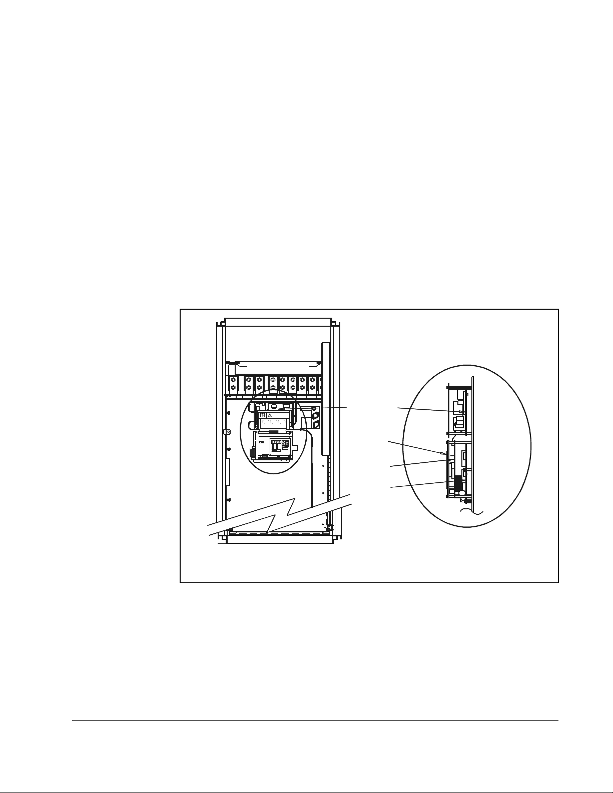
Step 3. Remove the Keypad Bracket from the Drive
Refer to figure 3.14 for component locations.
POWER CONNE CTIONS
POWER CONNE CTIONS
FULL SHIELD TABS IN AND ROTATE SHIELD OUT
FULL SHIELD TABS IN AND ROTATE SHIELD OUT
CONNE C T USI NG 360MCM TW O HOLE TE RM IN AL LUG S
CONNE C T USI NG 360MCM TW O HOLE TE RM IN AL LUG S
TORQUE TO 32 5IN-LB
TORQUE TO 32 5IN-LB
Wiring Tray
DC–
DC–
GND
GND
GND
GND
WT1 WT2VRL1WWT3
WT1 WT2VRL1WWT3
DC+
DC+
U
U
DC+
DC+
DC–
DC–
DANGER
DANGER
SL2 T
SL2 T
RST
RST
Wiring Tray
Power Module
Interface Board
RUNNING
RPM
RUNNING
RPM
REMOTE
VOLTS
REMOTE
VOLTS
JOG
AMPS
JOG
AMPS
Hz
Hz
AUTO
AUTO
FORWARD
Kw
FORWARD
Kw
REVERSE
TORQUE
REVERSE
TORQUE
PROGRAM
Password
PROGRAM
Password
ENTER
ENTER
STOP
STOP
START
START
RESET
RESET
Keypad
Regulator
Board
LonWorks
Side View
(Enlarged)
Front View
Figure 3.14 – LonWorks Module Location in 200 to 400HP @ 460VAC Drives
Step 3.1 Record connections to the Regulator board terminal strip if they must be
disconnected to remove the keypad bracket.
Step 3.2 Use a magnetic screwdriver to remove the four screws and lock washers
that fasten the keypad bracket to the hinged mounting panel. Hold the
keypad bracket as you remove the screws.
Step 3.3 Disconnect the Regulator board ribbon cable from the Power Module
Interface board.
Installing the LonWorks Module in the Drive
3-27
Page 42

Step 4. Install the LonWorks Module
ATTENTION:The drive contains ESD- (Electrostatic Discharge)
sensitive parts and assemblies. Static control precautions are required
!
Step 4.1 Remove the LonWorks module from its anti-static wrapper. Align the key on
Step 4.2 Align the LonWorks module’s four mounting holes with the four standoffs on
Step 4.3 Fasten the board to the drive with four 7/32″ nuts. Metal nuts must be used
Step 4.4 Remove the LonWorks module from its anti-static wrapper. Align the key on
when installing, testing, servicing, or repairing the drive. Erratic machine
operation and damage to, or destruction of, equipment can result if this
procedure is not followed. Failure to observe this precaution can result
in bodily injury.
the Regulator board’s 34-conductor ribbon cable connector with the slot in
the LonWorks module’s connector. Press the ribbon cable connector in until
it locks into position.
The LonWorks module mounts on four standoffs behind the Regulator
board.
the hinged mounting panel of the drive.
for proper grounding of the LonWorks module.
the Regulator board’s 34-conductor ribbon cable connector with the slot in
the LonWorks module’s connector. Press the ribbon cable connector in until
it locks into position.
Step 5. Reinstall the Keypad Bracket in the Drive
Step 5.1 Align the key on the connector from the Regulator board with the key of the
connector on the Power Module Interface board. Press the ribbon cable
connector in until it locks into position.
Step 5.2 Reconnect the keypad bracket to the hinged mounting panel using the four
screws removed earlier.
Step 5.3 Reconnect any wiring that was removed from the Regulator board terminal
strip. Refer to the terminal connections documented in step 3.1 or to the
appropriate instruction manuals for the devices being used.
Step 5.4 Close and secure the outer cabinet door of the drive.
3-28
LonWorks Module for VTAC 7 Drives
Page 43

CHAPTER 4
Connecting the Drive to the Network
and Applying Power
ATTENTION:The drive may contain high voltages that can cause injury
or death. Remove all power from the drive, then verify power has been
!
4.1 Connecting the Drive to the Network
Before connecting the drive to the network, verify that the module has been installed
in the drive according to the instructions provided in chapter 3. Then use the following
procedure to connect the drive to the network:
Step 1. Verify that po wer is removed from the network and drive.
Step 2. Use static control procedures.
removed before installing or removing a LonWorks module. Failure to
observe these precautions could result in severe bodily injury or loss of
life.
Step 3. Route the network cable through the bottom of the drive (or as described in
the VTAC 7 User Manual). Refer to table 2.2 in chapter 2 for recommended
network cables.
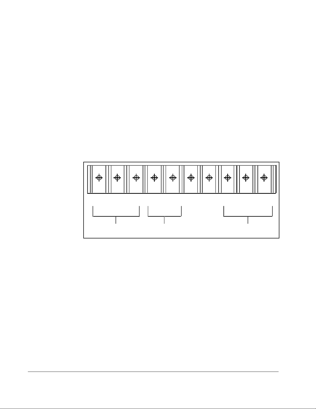
Step 4. Connect the network cable to the 5-screw terminal block on the LonWorks
module. Refer to table 4.1 for the terminal definitions.
Table 4.1 – Terminal Block Terminal Definitions
Pin Name Function
1 SHIELD Shield connection
2 NC Not used
3 NC Not used
4 NET A LonWorks NET A connection
5 NET B LonWorks NET B connection
4.2 Terminating the Ne twork
The LonWorks module does not provide built-in termination. Refer to the FTT-10A
Free Topology Transceiver User’s Guide (doc.id078-0156-01F) for more information
about terminating a LonWorks network (available at http://www.echelon.com).
Connecting the Drive to the Network and Applying Power
4-1
Page 44

4.3 Applying Power
ATTENTION:Unpredictable operation may occur if parameter settings
and switch settings are not compatible with your application. Verify that
!
Step 1. Close the drive cover or re-install the cover on the drive.
Step 2. Apply power to the drive. The module receives its power from the connected
Step 3. Apply power to the other devices on the network.
When to press service pin?
setting are compatible with your application before applying power to the
drive. Failu re to obse rve thes e precaut ions cou ld result in severe bo dily
injury or loss of life.
drive.
(Check LEDs on VTAC?)
4-2
LonWorks Module for VTAC 7 Drives
Page 45

CHAPTER 5
Installing the Drive as a Node
in the Network
ATTENTION:This procedure requires power be applied to the drive and
the network while the cover is off of the drive. The user is responsible
!
The module is installed as a node in the LonWorks network using a standard
LonWorks installation tool such as LonMaker for Windows. Refer to the tool-specific
instruction manual for more information.
for ensuring safe conditions for operating personnel. Failure to observe
this precaution could result in severe bodily injury or loss of life.
To identify the drive to the network, press the service pin shown in figure 5.1.
do this? Should this be part of chapter 4? How do you verify the results of
pressing the pin?)
When you have completed this procedure, re-install the drive cover.
Service Pin
Figure 5.1 – Location of the Service Pin on the LonWorks Module
(When to
Installing the Drive as a Node in the Network
5-1
Page 46

5-2
LonWorks Module for VTAC 7 Drives
Page 47

Programming the Drive
for Network Communication
This section describes how to configure a VTAC 7 drive for use with an LonWorks
network. The sections that follow describe the VTAC 7 parameters related to
LonWorks network operation. For other drive parameter descriptions, refer to the
VTAC 7 User Manual.
6.1 Setting the Control Source (P.000)
Parameter Range: LOCL = Local keypad/display
rE = Terminal strip remote inputs
OP = Option port
SErL = Serial port (CS3000 or OIM)
Default Setting: LOCL
Parameter Type: Configurable
CHAPTER 6
Parameter P.000 (Control Source) selects the source of control information for the
drive (start, jog, direction, etc.). To start and stop the drive over the network,
parameter P.000 must be set to OP. This parameter can be written over the network
only when the drive is stopped.
After parameter P.000 is set to OP, the Remote LED on the keypad should turn on to
show the network is in control of the drive. Note that parameter P.000 does not
prevent the drive from communicating on the network; it only allows the drive to be
controlled and the reference to be supplied from the network.
not have to be set to OP to modify or read drive parameters. True?
Parameter P.000 does
Programming the Drive for Network Communication
6-1
Page 48

6.2 Setting the Network Connection Type (P.061)
Parameter Range: 0 = Basic drive connection
1 = Full drive connection
Default Setting: 0
Parameter Type: Configurable
Refer also to paramete rs: N/A
Parameter P.061 (Network Connection Type) selects the type of network connection.
Setting P.061 = 1 provides full drive control from the network. Any drive data that has
been assigned a network register is transferred over the network. Parameter P.061
must be set to 1 to configure the drive over the network and have access to most
parameters, operating variables, and diagnostic information. The LonWorks module
will fault the drive if P.061 is not set to 1.
6.3 Setting the Commu nication Loss Response (P.062)
Parameter Range: 0 = IET fault
1 = Hold last reference
2 = Use terminal strip reference
Default Setting: 0
Parameter Type: Tunable
Refer also to paramete rs: P.000 Control Source
Parameter P.062 (Communication Loss Response) specifies how the drive responds
to a network communication loss when the Control Source (P.000) parameter is set to
OP (Option port).
If the option port is not in control of the drive, but is only monitoring drive operation,
then loss of network communications has no effect on drive operation. In all cases, the
LonWorks module, upon loss of communication with the network, will attempt to
re-establish the communication link.
T o eliminate extraneous fault conditions when a drive configured for network operation
is powered up, the drive will delay for approximately 20 seconds after power up before
annunciating a fault condition. A fault condition will be annunciated if network
communication is not established before the 20-second power-up timer expires, or if
network communication was established and then lost.
If the drive loses communication with the network, overspeed protection for the drive
will be in effect under all circumstances. you program overspeed protection in H.022.
When the motor goes above the overspeed limit, the drive faults and stops.
6-2
LonWorks Module for VTAC 7 Drives
Page 49

P.062 Option Port: Communication Loss Response
If P.062 = 0
The drive will consider a loss of network communication to be a drive fault, resulting in
an IET-type stop sequence.
When P.062 is set to IET fault (0) and communication is lost:
(continued)
• The drive latches a fault condition and performs a coast stop.
• The network communication loss fault is generated (nCL is displayed).
• The front panel REMOTE LED blinks, indicating that the network is inactive.
When network communication is re-established, you must reset the fault before the
drive can be re-started. See the VTAC 7 User Manual for information on resetting
faults. (A fault reset does not clear the error log.)
If P.062 = 1
The drive continues to operate, using the last reference received from the network.
ATTENTION:In volts/hertz regulation, if P .000 (Control Source) is set to
OP (Option Port), and P .062 is set to 1 (hold last reference), and the drive
!
loses communication with the network, the drive will maintain the last
frequency command sent to it. Ensure that drive machinery , all drive-train
mechanisms, and application material are capable of safe operation at
the maximum operating speed of the drive. Failure to observe this
precaution could resu lt in bodily inj ur y.
ATTENTION:When P.055 is set to
functional only from the selected control source. As a safety precaution,
Rockwell Automation recommends that an emergency stop pushbutton
be located near the drive in an easily accessible location. As a further
safety precaution, the user should post a warning on the drive to alert
personnel that the
this precaution could result in severe bodily injury or loss of life.
STOP/RESET key is not functional. Failure to observe
ON, the STOP/RESET key is
The response to network communication loss is:
• The drive continues to operate, using the last reference received from the network
master.
• An entry is made into the drive’s error log for each active-to-inactive transition of
network communicat ion status .
• The front panel REMOTE LED blinks, indicating that the network is inactive.
If network communication is re-established, the drive will again follow the reference
and sequencing control inputs supplied by the network. Note that if P.054 = ON and
the start and stop inputs are on (1), the drive will start.
Note that in this configuration, it might not always be possible to stop the drive over
the network.
Programming the Drive for Network Communication
6-3
Page 50

P.062 Option Port: Communication Loss Response
If P.062 = 2
The drive gets its speed/torque reference from the terminal strip analog input and its
stop input from the terminal strip stop input. All other inputs are held at the last values
received from the network.
This allows the network to continue controlling the drive reference with a direct-wired
analog output to input, and to stop the drive with a direct-wired digital output to input.
Note that if P.054 (Level Sense Start Enable) = OFF and the drive is stopped while in
this mode, it cannot be re-started until network communication is re-established or the
Control Source (P.000) is changed.
ATTENTION:If P.062 = 2 and P.054 (Level Sense Start Enab le) = ON
and network communication is lost while the drive is running, the terminal
!
Note that in this configuration, it might not always be possible to stop the drive over
the network.
strip stop input will function as a STOP/RUN input. If the terminal strip
stop input is opened, the drive will stop. If the terminal strip stop input is
closed, the drive will re-start. Failure to observe this precaution could
result in severe bodily injury or loss of life.
(continued)
The response to network communication loss is:
• The drive continues to operate, using the analog input from the Regulator board
terminal strip.
• An entry is made into the drive’s error log for each active-to-inactive transition of
network communicat ion status .
• The front panel REMOTE LED blinks, indicating that the network is inactive.
If network communication is re-established, the drive will again follow the reference
and sequencing control inputs supplied by the network. Note that if P.054 = ON and
the start and stop inputs are on (1), the drive will start.
ATTENTION:The drive is not equipped with a coast-stop pushbutton.
You must install a hardwired operator-accessible pushbutton that
!
provides a positive interrupt and shuts down the drive. See the drive
hardware instruction manual for wiring information. Failure to obser ve
this precaution could result in bodily injury.
6-4
LonWorks Module for VTAC 7 Drives
Page 51

6.4 Setting the Speed Display Scale (P.028)
Parameter Range: 10 to 9999
Default Setting: Synchronous speed based on H.001 (assuming a
4-pole motor)
Parameter Type: Tunable
Parameter P.028 (Speed Display Scaling) defines the scaling value applied to the
manual reference, the selected speed reference, and the output speed displays.
P.028 must be set to 100 for nvoDriveSpeed to show the correct percent of nominal
speed. This value is written by the LonWorks board at start up.
Refer to the VTAC 7 User’s Guide for more information about P.028.
6.5 Setting the Netw ork Output Register Sourc es (P.066
to P.069)
Parameters P.066 through P.069 define the signals written to network output registers
1 through 4. These parameters read/write over the network. Set these parameters as
follows:
• P.066 = 0 (Motor Kw display value)
• P.067 = 7 (Outer control loop error)
• P.068 = 8 (Outer control loop output)
• P.069 is not used.
Programming the Drive for Network Communication
6-5
Page 52

6-6
LonWorks Module for VTAC 7 Drives
Page 53

CHAPTER 7
Operating the Drive
Using a LonMark Profile
A LonMark profile defines the functional profile for a node communicating with other
nodes. The profile specifies which SNVTs (Standard Network Variable Types) and
SCPTs (Standard Configuration Property Types) are used, and provides a semantic
meaning about the information being communicated.
When a profile is implemented in a node, it’s called a LonMark object. One node can
have several objects implemented. The LonWorks module has two objects: a node
object and a drive object. The node object is used to control the other objects in a
node. See figure 7.1
Node Object
nviRequest
nv1
SNVT_obj_request
The drive object is based on a specific LonMark functional profile, as shown in figure
7.2.
Data exchange on a LonWorks network is handled with Standard Network Variable
Types (SNVTs), which represent different types of standard data (e.g., temperature,
pressure, voltage). The LonWorks module contains a fixed setup of SNVTs, and each
SNVT is mapped to a VTAC 7 drive parameter.
A network variable is any data item (such as temperature or a switch value) that a
particular device application program expects to receive from other devices on the
network (called an input network variable or NVI) or expects to make available to other
devices on the network (called an output network variable or NVO).
When a program writes into one of its output network variables, the new value of the
network variable is propagated across the network to all nodes with input network
variables connected to that output network variable.
Mandatory
Network
Variables
Figure 7.1 – Node Object
nv2
nvoStatus
SNVT_obj_status
Specific network variables are described in sections 7.1 through 7.3.
Operating the Drive Using a LonMark Profile
7-1
Page 54

nv1
nv2
nviDrvSpeedStpt
SNVT_switch
nviD r vSpeedScale
SNVT_lev_percent
nc17 - nciLoc ation (optional)
Variable Speed Motor
Drive: 6010
Mandatory
Network
Variables
Optional
Network
Variables
Configuration Properties
nc50 - nciMaxSpeed (mandatory)
nc53 - nciMinSpeed (mandatory)
nc48 - nciRcvHrtBt (optional)
nc49 - nciSndHrtBt (mandatory)
nc52 - nciMinOutTm (optional)
nc158 - nciNmlSpeed (mandatory)
nc159 - nciNmlFreq (m a nda tory)
nc160 - nciRam pUpTm (mand ato ry)
nc161 nciRampDownTm (mandatory)
nc162 nciDrvSp eedS ca le (optional)
nv5
nv6
nv7
nv8
nv9
nvoDrvSpeed
SNVT_lev_percent
nvoDrvCurnt
SNVT_amp
nvoDrvVolt
SNVT_vo lt
nvoDrvPwr
SNVT_power_kilo
nvoDrvRunHours
SNVT_time_hour
nv3
nv4
nviJogSel
SNVT_switch
nviOCL_enable
SNVT_switch
Manufacturer
Defined
Network
Variables
Manufacturer defined Configuration Properties
ncRA1 nciParRdA dr
ncRA2 nciParW riAdr
ncRA3 nciParW riData
ncRA4 nciJogRe f
ncRA5 nciCurLimit
nv10
nv11
nv12
nv13
nv14
nv15
nv16
nvoDrvStatus 1
SNVT_state
nvoDrvStatus 2
SNVT_state
nvoOCL_F B
SNVT_count
nvoOCL_ loop_ ou t
SNVT_lev_p ercent
nvoParam
SNVT_count
nvoFault1
SNVT_state
nvoFault2
SNVT_state
7-2
Figure 7.2 – Drive Object
LonWorks Module for VTAC 7 Drives
Page 55

7.1 Input Network Variables (NVIs)
Section 7.1 describes the input network variables (NVIs).
Node Object Request
Definition: network input SNVT_obj_request nviObjRequest;
Explanation: Enables control commands and updates from the network. The
status of the node is reported in nvoObjStatus (see section 7.2).
Range:
• RQ_NORMAL is the normal request mode when node is in
normal run mode.
• RQ_DISABLED will stop the motor.
• RQ_ENABLE enables start of motor again after an
RQ_DISABLED request; otherwise, the same as
RQ_NORMAL.
• RQ_UPDATE_STATUS updates nvoObjStatus.
• RQ_CLEAR_STATUS clears nvoObjStatus.
• RQ_CLEAR_ALARM resets a fault in the drive, sets
drvSpeedStpt.value = 0 and drvSpeedStpt.state = 0. Uses
Drop1, Register 32, bit 2 (Fault Reset). This is the only way to
reset a Receive Heartbeat Timeout fault.
• RQ_REPORT_MASK reports supported bits in nvoObjStatus.
• RQ_PROGRAM controls the Tune/Config enable bit in Drive
Control Word.
If RQ_SELF_TEST,
RQ_OVERRIDE,
RQ_RMV_OVERRIDE,
RQ_ALARM_NOTIFY_ENABLED,
RQ_ALARM_NOTIFY_DISABLED,
RQ_MANUAL_CTRL,
RQ_REMOTE_CTRL,
RQ_RESET,
RQ_CLEAR_RESET,
OR RQ_NUL is requested, the invalid_request will be set in
nvoObjStatus.
Operating the Drive Using a LonMark Profile
7-3
Page 56

Drive Speed Setpoint
Definition: network input SNVT_switch nviDrvSpeedStpt.
Explanation: Provides a low-resolution speed setpoint. When
nviDrvSpeedStpt.State is set to zero, the drive stops based on
the stop mode defined by drive parameter P.025.
Important: Requested speed will not be greater than the value
defined by nciMaxSpeed or less than the value
defined by nciMinSpeed
Range:
State Percent Value Requested Speed
0 N/A Stopped
10% 0%
1 0.5% to 100.0% 0.5 to 100.0%
1 100.0% 100.0%
0xFF N/A Auto (Invalid)
Default: Auto (state = 0xFF). This value will be adapted at power up. This
variable may use the Receive Heartbeat function if the Receive
Heartbeat function is set up for use. The actual value of drive
speed also depends on nviDrvSpeedScale.
Scaling: See section 8.4.
Speed Setpoint Scaling
Definition: network input SNVT_lev_percent nviDrvSpeedScale;
Explanation: Provides scaling for nviDrvSpdStpt. For example, if
nviDrvSpeedStpt value is 100% and nviDrvSpeedScale value is
-150%, then actual speed setpoint value is -150% (meaning
reverse 1.5 times nominal speed). The requested speed will not
be greater than the value defined by nciMaxSpeed or less than
the value defined by nciMinSpeed.
7-4
Range: -163.84 to 163.83%
Default: Defined by nciDrvSpeedScale.
Scaling: See section 8.4.
LonWorks Module for VTAC 7 Drives
Page 57

Run/Jog Select
Definition: network input SNVT_switch nviJogSel
Explanation: Selects run mode or jog mode for the drive.
• Jog reference frequency is defined by nciJogRef.
• Start/stop jogging the drive with nviSpeedStpt.state.
• For reverse operation, set (nviSpeedScale *
nviSpeedStpt.value) negative
Range: 0 = Run Mode
1 = Jog Mode
.
OCL Enable
Definition: network input config SNVT_switch nviOCL_enable
Explanation: Enables the Outer Control Loop (OCL).
Range: 0 = Disabled
1 = Enabled
Operating the Drive Using a LonMark Profile
7-5
Page 58

7.2 Output Network Variables (NVO)
Section 7.2 describes the output network variables (NVOs).
Node Object Status
Definition: network output SNVT_obj_status nvoObjStatus
Explanation: Reports node object status. It is updated every time there is a
status change. See Node Object Request in section 7.1.
Range:
Status Reported Definition
Invalid_request The node has been asked for an
unsupported request.
Report_mask Report supported fields.
Locked out LonWorks module does not have access
to all drops (P.061 <> 1).
In_alarm The drive is faulted. (Drop 1, Register 0,
bit 2.)
Manual_control The drive is in manual mode (the
AUTO/MAN key on the drive is set to
MAN), or it is not possible to run the drive
from the network (P.000 <> 2.)
Feedback_failure A parameter in the drive was not updated
as expected. The driv e sets this when the
tune/cfg bit is set in the command word.
The tune/cfg bit is se t from t he Lon W orks
module when using RQ_PROGRAM or
when setting an NCI that writes to the
drive.
Invalid ID An identification number other tha n 0 or 1
has been set in request by SNVT
nviObjRequest. The request will not be
carried out.
???
7-6
.
Drive Status 1
Definition: network output SNVT_state nvoDrvStatus1
Explanation: Provides the status word of the drive (Status Word 1).
Drive Status 2
Definition: network output SNVT_state nvoDrvStatus2
Explanation: Provides the status word of the drive (Status Word 2).
LonWorks Module for VTAC 7 Drives
Page 59

Drive Current
Definition: network output SNVT_amp nvoDrvCrnt
Explanation: Provides the drive ou tput current in amps.
Drive Speed
Definition: network output SNVT_level_percent nvoDrvSpeed
Explanation: Provides the speed of the drive as a percentage of the nominal
speed. Since nominal speed and nominal frequency are tightly
connected, the output value is calculated on the nominal (base)
frequency and the running (output) freque nc y. This variable is
used as a heartbeat to monitor the health of the LonWorks
communication interface. See section 7.3 for information about
heartbeats.
.
Drive Power
Definition: network output SNVT_power_kilo nvoDrvPwr;
Explanation: Provides the drive power in kilowatts. The LonWorks module
sets this at start up. Note that VTAC 7 parameter P.066
(Network Output Register 1 Source) must be set to 0.
Drive Voltage
Definition: network output SNVT_volt nvoDrvVolt
Definition: Provides the drive voltage in volts.
.
Operation Hour Counter
Definition: network output SNVT_time_hour nvoDrvRunHours;
Explanation: T otal power-on time in whole hours.
, this will have a granularity of 24 hours.
(?)
Since drive report by days
OCL Loop Output
Definition: network output SNVT_lev_percent nvoOCL_loop_out
Explanation: Provides OCL Loop output from the drive. The LonWorks
Operating the Drive Using a LonMark Profile
module sets this at start up. Note that VTAC 7 parameter P.068
(Network Output Register 3 Source) must be set to 8.
7-7
Page 60

Fault Word 1
Definition: network output SNVT_state nvoFault1
Explanation:
Range:
Bit Description
Bit Description
0 Overcurrent steady state
0 Overcurrent steady state
1 Overcurrent while accelerating
1 Overcurrent while accelerating
2 Overcurrent while decelerating
2 Overcurrent while decelerating
3 Overcurrent during DC braking
3 Overcurrent during DC braking
4 DC bus too high
4 DC bus too high
5 DC bus too low
5 DC bus too low
6 Electronic thermal overload
6 Electronic thermal overload
7 Therm ostat overtemp erature
7 Therm ostat overtemp erature
8 Function loss
8 Function loss
9 EPROM defaults restored
9 EPROM defaults restored
10 Loss of communication from serial port
10 Loss of communication from serial port
11 Spurious UART interrupt
11 Spurious UART interrupt
12 Torque/current self-tuning fault
12 Torque/current self-tuning fault
13 Overspeed (10% over max speed)
13 Overspeed (10% over max speed)
14 Output phase loss
14 Output phase loss
15 Overfrequency
15 Overfrequency
Fault Word 2
Definition: network output SNVT_state nvoFault2
Explanation:
Range:
Bit Description
0 Network communication loss
1 Bypass contact failure
2 High-time identification aborted
3 Drive not identified
4 High line voltage
5 Write to EEROM failure
6 Power unit overload
7 Earth current failure
8 Asymmetrical bus charge
9 Missing power unit ID connector
10 Unselected power unit
11 Input phase loss
12 Encoder loss
13 Analog input loss (4-20 mA input < 1 mA)
14 Unused
15 Fatal system error
7-8
LonWorks Module for VTAC 7 Drives
Page 61

Parameter V alue Out
Definition: network output SNVT_count nvoParam
Explanation: Used as feedback variable for generic parameter requests. See
nciParRdAddress (section 7.3).
7.3 Configuration Prop erties (NCIs)
This section describes the configuration properties (NCIs).
If an NCI has a corresponding parameter in the drive, it is written to with the value of
the NCI at the following times:
• When the NCI is updated from the network
• When the node is brought online
• When power is cycled to the drive
• When the drive is faulted and the error is reset from the LonWorks module.
Send Heartbeat
Definition: network input config SNVT_time_sec nciSndHrtBt
Explanation: Provides the maximum time between propagates (update of
value to network) for the variable nvoDrvSpeed. This NCI is
overridden by nciMinOutTm. If nciMinOutTm is longer, nothing
will be output, even if nciSndHrtBt has timed out.
Range:
Default: 0.0 (Disabled)
Same as Receive Heartbeat?
Receive Heartbeat
Definition: network input config SNVT_time_sec nciRcvHrtBt
Explanation: Selects the maximum time that can elapse between updates of
the input network variable nviDrvSpeedStpt before a fault is
reported to the drive. The drive will handle the fault as specified
by parameter P.062.
The fault can be reset only from the LonWorks module. Set
nviObjRequest to RQ_CLEAR_ALARM
Range: 0.0 (Disabled) to 6,5553.4 seconds
Default: 0.0 (Disabled)
.
Operating the Drive Using a LonMark Profile
7-9
Page 62

Minimum Send Time
Definition: network input config SNVT_time_sec nciMinOutTim;
Explanation: Selects the minimum period of time that expires before the
network output variables can be resent. This is good for limiting
use of bandwidth on the LonWorks channel. NciMinOutTm
parameter overrides nciSndHrtBt.
Range: 0.0 (Disabled) to 6,5553.4 seconds
Default: 0.0 (Disabled)
Location Label
Definition: network input config SNVT_str_asc nciLocation;
Explanation: Can be used to provide more descriptive physical location
information than can be provided by the Neuron chip’s 6-byte
location string. The location relates to the object and not to the
node.
Default: Empty spaces
Motor Nominal Speed
Definition: network input config SNVT_rpm nciNmlSpeed;
Explanation: Provides the nominal speed (RPM) of the motor. This is used
only when the drive is in Vector mode.
Default: Read from drive
(Not used in VTAC?)
Nominal Frequency
Definition: network input config SNVT_freq_hz nciNmlFreq
Explanation: Provides the nominal frequency of the motor. This value is
necessary to determine the minimum and maximum frequency.
Default: Read from drive
7-10
LonWorks Module for VTAC 7 Drives
Page 63

Minimum Speed
Definition: network input config SNVT_lev_percent nciMinSpeed
Explanation: Defines the minimum speed of a motor (around zero). Its value
is entered as a percent of nominal frequency, as defined by the
nominal frequency (nciNmlFreq) configuration value. Set this
parameter when the drive is stopped. NciMinSpeed will be in
effect on the next frequency setting.
If nciNmlFreq = 50 Hz and nciMinSpeed = 10%, the minimum
frequency is 5 Hz.
-163.84 ≤ minimum speed ≤ maximum speed ≤ 163.83
Default: Read from drive
Ramp Up Time
Definition: network input config SNVT_time_sec nciRampUpTm;
Explanation: Sets the ramp-up time.
Default: Read from drive
Ramp Down Time
Definition: network input config SNVT_time_sec nciRmapDownTm;
Explanation: Sets the ramp-up time. Optionally, this configuration property
can be used to set the ramp-down time.
Default: Read from drive
Jog Reference
Definition: network input config SNVT_count nciJog Ref
Explanation: Set the jog reference for the drive. For reverse operation, set
(nviSpeedScale * nviSpeedStpt.value) negative.
Default: Read from drive
Scaling: Scaling: Hz / RPM set in drive: nciJogRef / 10.
Operating the Drive Using a LonMark Profile
7-11
Page 64

Current Limit
Definition: network input config SNVT_lev_percent nciCurLimit
Explanation: Sets the current limit in percent of motor nameplate amps.
Default: Read from drive
Generic Parameter Register Setting, Write
Definition: network input config SNVT_count nciParWriAddress
Explanation: Selects register to write to in the drive. The first digit is the drive
drop number. The remaining digital represent the register. For
example, 203 = drop 2, register 3. See section 8.5 for more
information
Range: 000-063 = Drop 0
100-163 = Drop 1
200-263 = Drop 2
300-363 = Drop 3
.
Parameter V alue, Write
Definition: network input config UNVT_sj300 nciParWriValue;
Explanation: Value that is written to nciParWriAddress. See section 8.5 for
more information.
Range: 000-063 = Drop 0
100-163 = Drop 1
200-263 = Drop 2
300-363 = Drop 3
7-12
LonWorks Module for VTAC 7 Drives
Page 65

Generic Parameter Register Setting, Read
Definition: network input config SNVT_count nciParRdAddress;
Explanation: Selects register in the drive to read. The first digit is the drive
drop number. The remaining digital represent the register. For
example, 203 = drop 2, register 3. See section 8.6 for more
information.
Default: Read from drive
Range: 000-063 = Drop 0
100-163 = Drop 1
200-263 = Drop 2
300-363 = Drop 3
Speed Setpoint Scaling Default Value
Definition: network input config SNVT_lev_percent nciDrvSpeedScale
Explanation: Sets its (?) value to nviDrvSpeedScale on every start up. See
Speed Setpoint Scaling in section 7.1.
Range: -163% to 163%
Default: 0
Operating the Drive Using a LonMark Profile
7-13
Page 66

7-14
LonWorks Module for VTAC 7 Drives
Page 67

Conditions Required for Operation
This chapter describes the conditions required for performing some common actions
and how the combination of SNVTs and SCPTs affect the operation of the drive.
8.1 General Guidelines
• The LonWorks module and the drive must be installed and configured correctly.
Note the following VTAC 7 parameter settings:
• P.061 = 1. This enables the LonWorks module to have full access to all
parameters in the drive. The LonWorks module will fault the drive if this is not set
correctly.
• P.000 = OP. This enables the drive to accept frequency settings and/or start/stop
commands from the LonWorks module.
• P.028 = 100. This enables nvoDriveSpeed to show the correct percentage of
nominal speed. This is written by the LonWorks module at start up.
• NCIs (network config ur ati on prope rti es) are usuall y onl y written to the drive. NC I
values are read from the drive only at start up, when resetting faults, and when an
offline-to-online transition occurs. This is done to ensure consistency of parameters
values on both the LonWorks network and in the drive.
CHAPTER 8
• The tune/cfg bit in the VTAC 7 command word will be set automatically by network
variables that have a parameter in the drive that require the tune/cfg bit to be set.
This will al so cause all ot h e r t u ne /c fg parameters to be re a d by t he drive. This i s th e
equivalent of setting nviObjRequest to RQ_PROGRAM.
8.2 Starting the Drive
The drive will output a frequency when
• nviDrvSpeedStpt.value is greater than zero
• nviDrvSpeedStpt.state is not equal to zero
• nviDrvSpeed Scale is not equal to zero
• RQ_ENABLE has been requested more recently than RQ_DISABLED
• The node is online
all
of the following conditions are met:
Conditions Required for Operation
8-1
Page 68

8.3 Stopping the Drive
The drive will stop using the stop mode selected in parameter P.025 if
following conditions are met:
• NviSpeedStpt.state is set to any value but 1
• The node is brought offline
• RQ_DISABLED is requested in nviObjRequest
8.4 Setting the Frequency
The actual value written to the LonWorks module =
(nviDrvSpeedStpt*0.5*nviDrvSpeedScale*0.005*nciNmlFreq*100) / (100*100)
Notes for above equation:
• Multiplied by 0.005 and 0.5 to scale the two LonWorks format values
• Nominal frequency is the base for scale and setpoint percent values
• Multiplied by 100 to fit LonWorks module format.
• Divided by (100*100) because the setting frequency is multiplied by two percent
values.
Refer to chapter 7 for information about nviSpeedStpt and nviSpeedScale.
any
of the
NviSpeedScale NviSpeedStpt .val ue NviSpeedStpt.state Resulting Speed
0% 0% 1 0 Hz
100% 0% 1 0 Hz
0% 100% 1 0 Hz
150% 100% 0 (Normal) Stop
150% 100% 1 1.5*1.0*Nomfreq
-75% 100% 1 -0.75*1.00*Nomfreq
150% 50% 1 1.5*0.50*Nomfreq
8.5 Writing Values to a VTAC 7 Register
To write a value to a VTAC 7 register:
Step 1. Change register in nciWriAddr.
Step 2. Change value in nciWriValue.
Changing the value in nciWriValue triggers the writing to a register in the LonWorks
module. Changing the address alone will not perform a write sequence.
To verify that the LonWorks module has accepted the value written to it, read it back
by setting nciRdAdr to the corresponding DP RAM feedback register. See Appendix B
for a list of registers.
8-2
LonWorks Module for VTAC 7 Drives
Page 69

NciWriAddr Address NciWriAddr nciWriValue nviObjRequest Result
159 Drop 1
Reg59
157 Drop 1
Reg57(C)
X X X X RQ_PROGRAM All tunable parameters re ad
If (nciWriAddr >
X63) = X63
X63 X63 X RQ_PROGRAM Address written to with X.
159 0 X Network Inertia Comp Reg
157 0 Not
RQ_PROGRAM
For example:
RQ_NORMAL
Enable is set to 0.
Trim Ref Source is set to 0
but not read in by drive.
(Configurable parameter)
in by drive. All configurable
parameters read if drive is
stopped.
LonWorks modul e takes
care of invalid values.
8.6 Reading Values from VTAC 7 Registers
The address set in nciRdReg is polled and the result is written to nvoParam as often
as the value on the address changes or the work load on the host application and
nciMinOutTime allows.
NCIRdAdr Address NvoParam
004 Drop0 Register 4 Value read at address
8.7 Resetting Faults
If an error occurs, the drive faults. The fault can be reset from the LonWorks module
by first removing the cause of the fault, then setting nviObjRequest to
RQ_CLEAR_ALARM. All drive-related NCIs will be updated with the current drive
value.
8.8 Priority of nciMinOutTm and nciSendHrtBt
NciMinOutTm has priority over nciSendHrtBt. This means that heartbeats will not be
sent as often as specified in nciSendHrtBt if nciMinOutTm has a longer time set.
Conditions Required for Operation
8-3
Page 70

8-4
LonWorks Module for VTAC 7 Drives
Page 71

CHAPTER 9
Troubleshooting the
LonWorks Module
and Network
ATTENTION:Checking the status indicators on the LonWorks module
requires power be applied to the drive and the network while the cover
!
This chapter contains information for troubleshooting the LonWorks module and
network.
9.1 Understanding the Status Indicators on the Module
The LonWorks module has four status indicators. See figure 9.1.
is off of the drive. The user is responsible for ensuring safe conditions
for operating personnel. Failure to observe this precaution could result
in severe bodily injury or loss of life.
The AnyBus card
also has an LED.
We need to show
this.
➀
➂
➁
➃
Number Status Indicator Refer to...
➀
➁
➂
➃
Sections 9.1.1 through 9.1.4 describe what the state of each status indicator means.
Note that if all status indicators are off, the module is not receiving power. Refer to
chapter 3 for installation instructions.
Module Status Section 9.1.1
Service LED Section 9.1.2
Wink LED Section 9.1.3
Communication Module Status Section 9.1.4
Figure 9.1 – Status Indicators on the LonWorks Module
Troubleshooting the LonWorks Module and Network
9-1
Page 72

9.1.1 Module Status LED
LED State Cause Corrective Action
Solid green Normal operation/power on None required.
Flashing
green
Flashing red Recoverable fault:
Initialization of AnyBus/VTAC 7
interface
Table 9.1 – Module Status LED: S tate Definitions
None required.
Solid red Unrecoverable fault (hardware
9.1.2 Service LED
LED State Cause Corrective Action
Off This node is configured and
Flashing
green
Solid green This node is unconfigured and
9.1.3 Wink LED
• 4 Hz:
• 2 Hz: Heartbeat timeou t
received.
• 1 Hz: Node is offline.
error).
Table 9.2 – Service LED: State Definitions
installed in a network.
This node has an application, but
it is not yet installed in a network
(unconfigured).
has no application. Indicates
errors detected by the Neuron
self-test routine.
Table 9.3 – Wink LED: State Definitions
• 4 Hz: Check that P.061 is set to
1 for full access to all drops.
• 2 Hz:
• 1 Hz:
Replace module.
None required.
Configure the application.
Configure node and load application.
9-2
LED State Cause Corrective Action
Off Normal state. None required.
Flashing red A wink command is received on
the LonWorks network.
None required.
LonWorks Module for VTAC 7 Drives
Page 73

9.1.4 Communication Module Status LED
Table 9.4 – Communication Module Status LED: State Definitions
LED State Cause Corrective Action
Solid green The module has been initiated
correctly and is functioning
properly.
Flashing red Software error. Restart the module.
Solid red A hardware error has occurred. Cycle power to the drive and
9.2 Error Handling
The LonWorks module handles errors in the following manner:
• If nciRcvHrtBt > 0, and heartbeats are not received within nciRcvHrtBt time, then
communication with the LonWorks network is considered down. This will result in a
net comm fault.
• The module responds as specified in Comm Loss Response.
• If the module does not get access to DP RAM in 250 ms, the comm_failure bit will
be set in the network output SNVT_obj_status nvoObjSatus. This will also result in a
net comm fault (force write in DP RAM without waiting on VTAC 7 drive).
None required.
module. If cycling power does not
correct the problem, replace the
module.
Internal VTAC 7 drive error codes are described in the drive register map (fault latch
bits word 1 and fault latch bits word 2).
AnyBus Module
Error
Drive cannot be fully
accessed. Not all drive
drop registers can be
accessed. Drop0 Reg 13
is not equal to 3 or
Drop0 Reg12 = 0.
Heartbeat timeout. Red 2 Hz Check connections, cables, and
Node offline. Red 1 Hz Set node online.
Status LED Corrective Action
Red 4 Hz Check the drive. Che ck setti ng of
P.061.
setup of send/rcv hrtbt
parameters. Recoverable fault
use RQ_CLEAR_ALARM.
Troubleshooting the LonWorks Module and Network
9-3
Page 74

Error LonWorks Module LED 1 Corrective Action
RAM error Three red flashes, then
constant red. The software
has detected a RAM
checksum error and has not
started the application and
never will.
Flash error. Six red flashes, then constant
red. The software has
detected a Flash checksum
error and has not started the
applicaiton and never will.
Hardware error. Red. Software application was
not started.
Drive cannot be fully
accessed. Not all drive
drop registers can be
accessed. Drop0 Reg 13
is not equal to 3 or
Drop0 Reg12 = 0.
Red 2 Hz Check the drive. Check
Unrecoverable fault. Try
restart.
Unrecoverable fault. The
software has been
damaged.
Unrecoverable fault. The
module may have been
seriously damaged.
the setting of parameter
P.061.
9-4
LonWorks Module for VTAC 7 Drives
Page 75

APPENDIX A
Technical Specifications
Communications
Network
Protocol LonWorks
Data Rates 78 kbps
Maximum bus length 2000 m
Maximum
node-to-node distance
Electrical
Consumption 300 mA on the +5 power connection (+/-5%)
Mechanical
Dimensions
Height 18 mm
Length 172 mm
Width 99 mm
Weight
500 m
Technical Specifications
Environmental
Temperature
Operating - 10 to 50 C (14 to 149 F)
Storage -40 to 85 C (-40 to 185 F)
Relative humidity 5 to 95% non-condensing
Regulatory Compliance
UL 508C and CUL
CE EN61800-3
A-1
Page 76

A-2
LonWorks Module for VTAC 7 Drives
Page 77

INDEX
Numerics
1 to 20 HP @ 230 VAC drive installation, 3-11
1 to 5 HP @ 460 VAC drive installation, 3-3
15 to 25 HP @ 460 VAC drive installation, 3-20
200 to 400 HP @ 460 VAC drive installation, 3-26
25 to 60 HP @ 460 VAC drive installation, 3-20
30 to 100 HP @ 230 VAC drive installation, 3-15
7.5 to 10 HP @ 460 VAC drive installation, 3-7
75 to 200 @ 460 VAC drive installation, 3-15
B
basic drive connection, 5-1
C
checklist, installation, 2-3
D
DC bus voltage terminals
1 to 20 HP @ 230 VAC drives, 3-12
1 to 5 HP @ 460 VAC drives, 3-4
15 to 25 HP @ 460 VAC drives, 3-21
25 to 60 HP @ 460 VAC drives, 3-22
7.5 to 10 HP @ 460 VAC drives, 3-8
75 to 100 HP @ 230 VAC drives, 3-16
75 to 100 HP @ 230 VAC drives (, 3-16
75 to 150 HP @ 460 VAC drives, 3-16
digital inputs
specifications, A-1
drops, 5-1
30 to 100 HP @ 230 VAC drives, 3-15
7.5 to 10 HP @ 460 VAC drives, 3-7
75 to 200 @ 460 VAC drives, 3-15
checklist, 2-3
S
software, VTAC 7 drives, 1-1
specifications, A-1
T
technical spec ifications,A-1
troubleshooting, 8-1, 9-1
V
VTAC 7 drive hardware/software, 1-1
H
hardware, VTAC 7 drives, 1-1
I
installation, 3-1
1 to 20 HP @ 230 VAC drives, 3-11
1 to 5 HP @ 460 VAC drives, 3-3
15 to 25 HP @ 460 VAC drives, 3-20
200 to 400 HP @ 460 VAC drives, 3-26
25 to 60 HP @ 460 VAC drives, 3-20
Index
Index-1
Page 78

Index-2
LonWorks Module for VTAC 7 Drives
Page 79

Page 80

U.S. Drives Technical Support
Tel: (1) 262.512.8176, Fax: (1) 262.512.2222, Email: support@drives.ra.rockwell.com, Online: www.ab.com/support/abdrives
Publication D2-3498– 2001 Copyright © 2001 Rockwell Automation, Inc. All Rights Reserved. Printed in USA.
 Loading...