

Page 1

User Manual
ArmorStart® LT Distributed Motor Controller
Catalog Numbers 290E, 291E, 294E
Page 2

Important User Information
IMPORTANT
Because of the variety of uses for the products described in this publication, those responsible for the application and use of
this control equipment must satisfy themselves that all necessary steps have been taken to assure that each application and
use meets all performance and safety requirements, including any applicable laws, regulations, codes and standards.
The illustrations, charts, sample programs and layout examples shown in this guide are intended solely for purposes of
example. Since there are many variables and requirements associated with any particular installation, Rockwell Automation
does not assume responsibility or liability (to include intellectual property liability) for actual use based upon the examples
shown in this publication.
Solid-state equipment has operational characteristics differing from those of electromechanical equipment. Safety
Guidelines for the Application, Installation and Maintenance of Solid State Controls (Publication SGI-1.1
local Rockwell Automation sales office or online at http://www.rockwellautomation.com/literature/
important differences between solid-state equipment and hard-wired electromechanical devices. Because of this difference,
and also because of the wide variety of uses for solid-state equipment, all persons responsible for applying this equipment
must satisfy themselves that each intended application of this equipment is acceptable.
In no event will Rockwell Automation, Inc. be responsible or liable for indirect or consequential damages resulting from the
use or application of this equipment.
The examples and diagrams in this manual are included solely for illustrative purposes. Because of the many variables and
requirements associated with any particular installation, Rockwell Automation, Inc. cannot assume responsibility or
liability for actual use based on the examples and diagrams.
available from your
) describes some
No patent liability is assumed by Rockwell Automation, Inc. with respect to use of information, circuits, equipment, or
software described in this manual.
Reproduction of the contents of this manual, in whole or in part, without written permission of Rockwell Automation,
Inc., is prohibited.
Throughout this manual, when necessary, we use notes to make you aware of safety considerations.
WARNING: Identifies information about practices or circumstances that can cause an explosion in a hazardous environment,
which may lead to personal injury or death, property damage, or economic loss.
ATTENTION: Identifies information about practices or circumstances that can lead to personal injury or death, property
damage, or economic loss. Attentions help you identify a hazard, avoid a hazard, and recognize the consequence.
SHOCK HAZARD: Labels may be on or inside the equipment, for example, a drive or motor, to alert people that dangerous
voltage may be present.
BURN HAZARD: Labels may be on or inside the equipment, for example, a drive or motor, to alert people that surfaces may
reach dangerous temperatures.
Identifies information that is critical for successful application and understanding of the product.
Page 3

General Precautions
In addition to the precautions listed throughout this manual, the following statements, which are general to the system,
must be read and understood.
ATTENTION: This manual is intended for qualified service personnel responsible for setting up and servicing these devices. The
user must have previous experience with and a basic understanding of electrical terminology, configuration procedures,
required equipment, and safety precautions.
WARNING: The National Electrical Code (NEC), NFPA79, and any other governing regional or local code will overrule the
information in this manual. Rockwell Automation cannot assume responsibility for the compliance or proper installation of the
ArmorStart LT or associated equipment. A hazard of personal injury and/or equipment damage exists if codes are ignored
during installation.
ATTENTION: The controller contains ESD (electrostatic discharge) sensitive parts and assemblies. Static control precautions are
required when installing, testing, servicing, or repairing the assembly. Component damage may result if ESD control
procedures are not followed. If you are not familiar with static control procedures, refer to Publication 8000-4.5.2
against Electrostatic Discharge, or any other applicable ESD protection handbooks.
, Guarding
ATTENTION: Only personnel familiar with the controller and associated machinery should plan or implement the installation,
startup, and subsequent maintenance of the system. Failure to do this may result in personal injury and/or equipment
damage.
Precautions for Bulletin 294E Applications
ATTENTION: Only qualified personnel familiar with adjustable frequency AC drives and associated machinery should plan or
implement the installation, startup, and subsequent maintenance of the system. Failure to do this may result in personal injury
and/or equipment damage.
Rockwell Automation Publication 290E-UM001B-EN-P - June 2012 3
Page 4

Software Requirements
The table lists the versions of software that are required.
Software Version
RSLinx Classic 2.56 or later
RSLogix 5000 17.01 or later
BOOTP/DHCP Version 2.3 or later
Download the most current version of the Add-On Profile from
http://www.rockwellautomation.com/support/downloads.html.
Additional Resources
These documents and websites contain additional information concerning related Rockwell Automation products.
You can view or download publications at http:/www.rockwellautomation.com/literature/
. To order paper copies of
technical documentation, contact your local Allen-Bradley distributor or Rockwell Automation sales representative.
Table 1 - Rockwell Automation Industrial Network Resources
Resource Description
http://ab.rockwellautomation.com/Networks-and-Communications
http://ab.rockwellautomation.com/Networks-and-Communications/Ethernet-IPNetwork
http://www.rockwellautomation.com/services/networks/
http://www.rockwellautomation.com/services/security/
http://www.ab.com/networks/architectures.html Education series webcasts for IT and controls professionals
EtherNet/IP Embedded Switch Technology Application Guide, Publication ENET-AP005 Describes how to install, configure, and maintain linear and device-level Ring (DLR)
EtherNet/IP Network Configuration User Manual, Publication ENET-UM001
EtherNet Design Consideration, Publication ENET-RM002A-EN-P Provides details on ethernet design and infrastructure.
EtherNet/IP Modules in Logix5000 Control Systems User Manual, Publication ENET-UM001
EtherNet/IP Embedded Switch Technology Application Guide, Publication ENET-AP005
EtherNet/IP Industrial Protocol White Paper, Publication ENET-WP001
Industrial Automation Wiring and Grounding Guidelines, Publication 1770-4.1
Wiring and Grounding Guidelines, (PWM) AC Drives, Publication DRIVES-IN001
Product Certifications website,
http://www.rockwellautomation.com/products/certification/
Describes how to implement services and data objects on a TCP/UDP/IP based Ethernet
Rockwell Automation networks and communication website
Rockwell Automation EtherNet/IP website
Rockwell Automation network and security services websites
networks using Rockwell Automation EtherNet/IP devices with embedded switch
technology.
Describes how to configure and use EtherNet/IP communication modules with a
Logix5000 controller and communicate with various devices on the Ethernet network.
Provides details about how to configure your module.
Provides information about using products with embedded switch technology to
construct networks with linear and ring topologies.
network.
Provides general guidelines for installing a Rockwell Automation industrial system.
Describes wiring and grounding guidelines for Pulse Width Modulated (PWM) AC Drives
Provides declarations of conformity, certificates, and other certification details.
4 Rockwell Automation Publication 290E-UM001B-EN-P - June 2012
Page 5

Table 2 - ODVA Resources
Resource Description
http://www.odva.org/ Open DeviceNet Vendors Association (ODVA) website
http://www.odva.org/default.aspx?tabid=54 The CIP Advantage website
Ethernet Media Planning and Installation Manual, ODVA publication
http://www.odva.org/Portals/0/Library/Publications_Numbered/
PUB00148R0_EtherNetIP_Media_Planning_and_Installation_Manual.pdf
Network Infrastructure for EtherNet/IP: Introduction and Considerations, ODVA publication
http://www.odva.org/Portals/0/Library/Publications_Numbered/
PUB00035R0_Infrastructure_Guide.pdf
• CIP features and benefits
• How to get started
Describes the required media components and how to plan for, install, verify,
troubleshoot, and certify an Ethernet network.
Provides an overview of the technologies used in EtherNet/IP networks and provides
guidelines for deploying infrastructure devices in EtherNet/IP networks.
Table 3 - Product Selection Resources
Resource Description
Industrial Controls catalog website,
http://www.ab.com/catalogs/
ArmorStart LT Distributed Motor Controller Selection Guide, Publication 290-SG001
Industrial Controls catalog website
Product selection g uide
Table 4 - Cisco and Rockwell Automation Alliance Resources
Resource Description
http://www.ab.com/networks/architectures.html
Converged Plantwide Ethernet (CPwE) Design and Implementation Guide, Publication
ENET-TD001
Rockwell Automation and Cisco Systems reference architecture website
Represents a collaborative development effort from Rockwell Automation and Cisco
Systems. The design guide is built on, and adds to, design guidelines from the Cisco
Ethernet-to-the-Factory (EttF) solution and the Rockwell Automation Integrated
Architecture. The design guide focuses on the manufacturing industr y.
Rockwell Automation Support
Rockwell Automation provides technical information on the Web to assist you in using its products. At
http://www.rockwellautomation.com/support/
, you can find technical manuals, a knowledge base of FAQs, technical
and application notes, sample code and links to software service packs, and a MySupport feature that you can customize
to make the best use of these tools.
Installation Assistance
If you experience a problem within the first 24 hours of installation, contact Customer Support.
United States or Canada 1.440.646.3434
Outside United States or
Canada
Use the Wo rldw ide L ocator
americas/phone_en.html, or contact your local Rockwell Automation representative.
at http://www.rockwellautomation.com/support/
Rockwell Automation Publication 290E-UM001B-EN-P - June 2012 5
Page 6

New Product Satisfaction Return
Rockwell Automation tests all of its products to ensure that they are fully operational when shipped from the
manufacturing facility. However, if your product is not functioning and needs to be returned, follow these procedures.
United States Contact your distributor. You must provide a Customer Support case number (call the
Outside United States Please contact your local Rockwell Automation representative for the return
phone number above to obtain one) to your distributor to complete the return process.
procedure.
6 Rockwell Automation Publication 290E-UM001B-EN-P - June 2012
Page 7

Summary of Changes
New and Updated Information
This table contains the changes made to this revision.
Top ic Pag e
Added source brake and IPS specifications Various
Rockwell Automation Publication 290E-UM001B-EN-P - June 2012 7
Page 8

Summary of Changes
Notes:
8 Rockwell Automation Publication 290E-UM001B-EN-P - June 2012
Page 9

Preface
European Communities (EC) Directive Compliance
Low Voltage and EMC Directives
If this product has the CE mark it is approved for installation within the
European Union and European Economic Area (EEA). It has been designed and
tested to meet the following directives.
This product is tested to meet the European Union (EU) Council 2006/95/EC
Low Voltage Directive and the EU Council 2004/108/EC Electromagnetic
Compatibility (EMC) Directive by applying the following standard(s):
• Bulletin 290E_/291E_: EN 60947-4-1 — Low-voltage switchgear and
controlgear — Part 4-1: Contactors and motor-starters — Electromechanical
contactors and motor-starters.
• Bulletin 294E_: EN 61800-3 — Adjustable speed electronic power drive
systems — Part 3: EMC product standard including specific test methods
EN 61800-5-1:2003 — Adjustable speed electrical power drive systems —
Part 5-1: Safety requirements — Electrical, thermal and energy.
This product is intended for use in an industrial environment.
Rockwell Automation Publication 290E-UM001B-EN-P - June 2012 9
Page 10

Preface
Introduction
The ArmorStart LT is an integrated, pre-engineered, motor starting solution
designed for use in material handling applications. ArmorStart LT is the latest
addition to the ArmorStart portfolio. ArmorStart LT is a leader in the market
place given its compact size and high performance features in network, I/O, and
motor control. This manual will guide you through the features and functionality
when installing the product. Thank you for choosing ArmorStart LT for your
distributed motor control needs. If you have any questions please refer to the
“Support Section” for contact information.
10 Rockwell Automation Publication 290E-UM001B-EN-P - June 2012
Page 11

Table of Contents
Important User Information . . . . . . . . . . . . . . . . . . . . . . . . . . . . . . . . . . . . . . . 2
General Precautions . . . . . . . . . . . . . . . . . . . . . . . . . . . . . . . . . . . . . . . . . . . . . . . . 3
Software Requirements . . . . . . . . . . . . . . . . . . . . . . . . . . . . . . . . . . . . . . . . . . . . . 4
Additional Resources . . . . . . . . . . . . . . . . . . . . . . . . . . . . . . . . . . . . . . . . . . . . . . . 4
Rockwell Automation Support . . . . . . . . . . . . . . . . . . . . . . . . . . . . . . . . . . . . . . 5
Installation Assistance . . . . . . . . . . . . . . . . . . . . . . . . . . . . . . . . . . . . . . . . . . . . . . 5
New Product Satisfaction Return . . . . . . . . . . . . . . . . . . . . . . . . . . . . . . . . . . . . 6
Summary of Changes
New and Updated Information. . . . . . . . . . . . . . . . . . . . . . . . . . . . . . . . . . . . . . 7
Preface
European Communities (EC) Directive Compliance. . . . . . . . . . . . . . . . . 9
Low Voltage and EMC Directives . . . . . . . . . . . . . . . . . . . . . . . . . . . . . . . . . . 9
Introduction. . . . . . . . . . . . . . . . . . . . . . . . . . . . . . . . . . . . . . . . . . . . . . . . . . . . . . 10
Chapter 1
Product Overview
Description . . . . . . . . . . . . . . . . . . . . . . . . . . . . . . . . . . . . . . . . . . . . . . . . . . . . . . 17
Features . . . . . . . . . . . . . . . . . . . . . . . . . . . . . . . . . . . . . . . . . . . . . . . . . . . . . . . . . 18
Feature Description . . . . . . . . . . . . . . . . . . . . . . . . . . . . . . . . . . . . . . . . . . . . . . 19
Standard Features Across Product Familly . . . . . . . . . . . . . . . . . . . . . . 19
Network Options . . . . . . . . . . . . . . . . . . . . . . . . . . . . . . . . . . . . . . . . . . . . . . . . 20
Factory Installed Options . . . . . . . . . . . . . . . . . . . . . . . . . . . . . . . . . . . . . . . . . 22
ArmorStart LT Characteristics Bulletin 290E/291E . . . . . . . . . . . . . . . . 23
Catalog Number Explanation Bulletin 290E/291E. . . . . . . . . . . . . . . . . . 24
ArmorStart LT Characteristics Bulletin 294E . . . . . . . . . . . . . . . . . . . . . . 25
Catalog Number Explanation Bulletin 294E. . . . . . . . . . . . . . . . . . . . . . . . . 26
Basic Operation . . . . . . . . . . . . . . . . . . . . . . . . . . . . . . . . . . . . . . . . . . . . . . . . . . .27
Group Motor Installations for USA and Canada Markets. . . . . . . . .27
Control Circuit . . . . . . . . . . . . . . . . . . . . . . . . . . . . . . . . . . . . . . . . . . . . . . .27
Motor Circuit. . . . . . . . . . . . . . . . . . . . . . . . . . . . . . . . . . . . . . . . . . . . . . . . . 29
Local I/O . . . . . . . . . . . . . . . . . . . . . . . . . . . . . . . . . . . . . . . . . . . . . . . . . . . . .29
Overload Protection . . . . . . . . . . . . . . . . . . . . . . . . . . . . . . . . . . . . . . . . . . .30
Mode of Operation Bulletin 290E/291E . . . . . . . . . . . . . . . . . . . . . . . . . . . .30
Full-Voltage Start. . . . . . . . . . . . . . . . . . . . . . . . . . . . . . . . . . . . . . . . . . . . . . 30
Mode of Operation Bulletin 294E . . . . . . . . . . . . . . . . . . . . . . . . . . . . . . . . . .31
Sensorless Vector Performance. . . . . . . . . . . . . . . . . . . . . . . . . . . . . . . . . .31
Status LEDs and Reset. . . . . . . . . . . . . . . . . . . . . . . . . . . . . . . . . . . . . . . . . . . . . 32
Electronic Data Sheet (EDS) . . . . . . . . . . . . . . . . . . . . . . . . . . . . . . . . . . .33
Fault Diagnostics. . . . . . . . . . . . . . . . . . . . . . . . . . . . . . . . . . . . . . . . . . . . . . . . . .34
Protection Faults . . . . . . . . . . . . . . . . . . . . . . . . . . . . . . . . . . . . . . . . . . . . . . 34
Optional HOA Selector Keypad. . . . . . . . . . . . . . . . . . . . . . . . . . . . . . . . . . . .35
Keypad Local Control . . . . . . . . . . . . . . . . . . . . . . . . . . . . . . . . . . . . . . . . .35
Optional HOA Keypad Configuration (Bulletin 290E/291E only). . . . 35
Rockwell Automation Publication 290E-UM001B-EN-P - June 2012 11
Page 12

Table of Contents
Optional HOA Selector Keypad
with Jog Function(Bulletin 294E only). . . . . . . . . . . . . . . . . . . . . . . . . . . . . .37
Keypad Local Control . . . . . . . . . . . . . . . . . . . . . . . . . . . . . . . . . . . . . . . . .37
Keypad and HOA Disable Parameter. . . . . . . . . . . . . . . . . . . . . . . . . . . .38
Source Brake Contactor and Connector (Bulletin 294E only). . . . . . . . . 38
Chapter 2
Installation and Wiring
Receiving . . . . . . . . . . . . . . . . . . . . . . . . . . . . . . . . . . . . . . . . . . . . . . . . . . . . . . . . .39
Unpacking. . . . . . . . . . . . . . . . . . . . . . . . . . . . . . . . . . . . . . . . . . . . . . . . . . . . . . . . 39
Inspecting . . . . . . . . . . . . . . . . . . . . . . . . . . . . . . . . . . . . . . . . . . . . . . . . . . . . . . . . 39
Storing . . . . . . . . . . . . . . . . . . . . . . . . . . . . . . . . . . . . . . . . . . . . . . . . . . . . . . . . . . . 39
Installation Precautions. . . . . . . . . . . . . . . . . . . . . . . . . . . . . . . . . . . . . . . . . . . .40
Precautions for Bulletin 290E/291E Applications. . . . . . . . . . . . . . . . . . . .40
Precautions for Bulletin 294E Applications. . . . . . . . . . . . . . . . . . . . . . . . . .40
Dimensions. . . . . . . . . . . . . . . . . . . . . . . . . . . . . . . . . . . . . . . . . . . . . . . . . . . . . . . 40
Bulletin 290E/291E . . . . . . . . . . . . . . . . . . . . . . . . . . . . . . . . . . . . . . . . . . . 41
Bulletin 294E . . . . . . . . . . . . . . . . . . . . . . . . . . . . . . . . . . . . . . . . . . . . . . . . .42
ArmorStart LT Gland Plate Matrix . . . . . . . . . . . . . . . . . . . . . . . . . . . . . 43
Connection Locations . . . . . . . . . . . . . . . . . . . . . . . . . . . . . . . . . . . . . . . . . . . . .43
Internal Power, Control, and Ground Locations . . . . . . . . . . . . . . . . .43
Gland Connection. . . . . . . . . . . . . . . . . . . . . . . . . . . . . . . . . . . . . . . . . . . . .44
Wiring Terminal Detail. . . . . . . . . . . . . . . . . . . . . . . . . . . . . . . . . . . . . . . . . . . .45
Branch Circuit Protection . . . . . . . . . . . . . . . . . . . . . . . . . . . . . . . . . . . . . . . . .46
Simple System Design . . . . . . . . . . . . . . . . . . . . . . . . . . . . . . . . . . . . . . . . . . . . .47
ArmorConnect Power . . . . . . . . . . . . . . . . . . . . . . . . . . . . . . . . . . . . . . . . . . . . .48
ArmorConnect Cable Ratings. . . . . . . . . . . . . . . . . . . . . . . . . . . . . . . . . . . . . . 49
Branch Circuit Protection Requirements for ArmorConnect
Three-Phase Power Media. . . . . . . . . . . . . . . . . . . . . . . . . . . . . . . . . . . . . . 49
Electrical Wiring . . . . . . . . . . . . . . . . . . . . . . . . . . . . . . . . . . . . . . . . . . . . . . . . . .50
Group Motor Installations for USA and Canada Markets . . . . . . . . . . . .55
Wiring . . . . . . . . . . . . . . . . . . . . . . . . . . . . . . . . . . . . . . . . . . . . . . . . . . . . . . . . . . .55
Cable Workmanship Guidelines . . . . . . . . . . . . . . . . . . . . . . . . . . . . . . . .55
Service Space . . . . . . . . . . . . . . . . . . . . . . . . . . . . . . . . . . . . . . . . . . . . . . . . . .56
Hand Operation (HOA) Considerations. . . . . . . . . . . . . . . . . . . . . . . . 56
General Wiring Considerations . . . . . . . . . . . . . . . . . . . . . . . . . . . . . . . . . . . .56
Grounding. . . . . . . . . . . . . . . . . . . . . . . . . . . . . . . . . . . . . . . . . . . . . . . . . . . . . . . .57
Grounding Safety Grounds. . . . . . . . . . . . . . . . . . . . . . . . . . . . . . . . . . . . .57
Grounding PE or Ground . . . . . . . . . . . . . . . . . . . . . . . . . . . . . . . . . . . . . .57
Grounding Motors . . . . . . . . . . . . . . . . . . . . . . . . . . . . . . . . . . . . . . . . . . . .57
Power Distribution. . . . . . . . . . . . . . . . . . . . . . . . . . . . . . . . . . . . . . . . . . . . . . . .58
Delta/Wye with Grounded Wye Neutral. . . . . . . . . . . . . . . . . . . . . . . .58
AC Line Voltage . . . . . . . . . . . . . . . . . . . . . . . . . . . . . . . . . . . . . . . . . . . . . . . . . .58
Line Reactor . . . . . . . . . . . . . . . . . . . . . . . . . . . . . . . . . . . . . . . . . . . . . . . . . . . . . .58
Bulletin 294E Motor Cable Considerations . . . . . . . . . . . . . . . . . . . . . . . . .59
Unshielded Cable . . . . . . . . . . . . . . . . . . . . . . . . . . . . . . . . . . . . . . . . . . . . .59
Shielded Cable . . . . . . . . . . . . . . . . . . . . . . . . . . . . . . . . . . . . . . . . . . . . . . . . 60
Recommended Cable Connectors/Glands . . . . . . . . . . . . . . . . . . . . . . .60
12 Rockwell Automation Publication 290E-UM001B-EN-P - June 2012
Page 13

Product Commissioning
Table of Contents
Recommended Cord Grips . . . . . . . . . . . . . . . . . . . . . . . . . . . . . . . . . . . . .61
Shield Terminating Connectors . . . . . . . . . . . . . . . . . . . . . . . . . . . . . . . .61
Electromagnetic Compatibility (EMC) . . . . . . . . . . . . . . . . . . . . . . . . . . . . .62
General Notes (Bulletin 294E only) . . . . . . . . . . . . . . . . . . . . . . . . . . . . .62
Ethernet, DeviceNet, and I/O Connections . . . . . . . . . . . . . . . . . . . . . . . . .63
ArmorConnect Power Media Receptacles . . . . . . . . . . . . . . . . . . . . . . . . . . . 64
Optional Locking Clip. . . . . . . . . . . . . . . . . . . . . . . . . . . . . . . . . . . . . . . . . . . . .65
Chapter 3
IP Address . . . . . . . . . . . . . . . . . . . . . . . . . . . . . . . . . . . . . . . . . . . . . . . . . . . . . . . .67
Gateway Address . . . . . . . . . . . . . . . . . . . . . . . . . . . . . . . . . . . . . . . . . . . . . .67
Subnet Mask . . . . . . . . . . . . . . . . . . . . . . . . . . . . . . . . . . . . . . . . . . . . . . . . . .67
Configuring EtherNet/IP Address. . . . . . . . . . . . . . . . . . . . . . . . . . . . . . . . . .68
Manually Configure the Network Address Switches . . . . . . . . . . . . . .68
Static Address Alternative . . . . . . . . . . . . . . . . . . . . . . . . . . . . . . . . . . . . . .69
Using the Rockwell Automation BootP/DHCP Utility . . . . . . . . . . . . . . 69
Save the Relation List . . . . . . . . . . . . . . . . . . . . . . . . . . . . . . . . . . . . . . . . . .72
Embedded Web Server . . . . . . . . . . . . . . . . . . . . . . . . . . . . . . . . . . . . . . . . . . . .74
Network Configuration. . . . . . . . . . . . . . . . . . . . . . . . . . . . . . . . . . . . . . . . 75
Parameter Configuration. . . . . . . . . . . . . . . . . . . . . . . . . . . . . . . . . . . . . . .76
E-mail Notification Configuration . . . . . . . . . . . . . . . . . . . . . . . . . . . . . .76
How to Add a New Module Using the Add-On Profile. . . . . . . . . . . . . . .78
Electronic Keying. . . . . . . . . . . . . . . . . . . . . . . . . . . . . . . . . . . . . . . . . . . . . .80
Connections . . . . . . . . . . . . . . . . . . . . . . . . . . . . . . . . . . . . . . . . . . . . . . . . . .81
Configured By . . . . . . . . . . . . . . . . . . . . . . . . . . . . . . . . . . . . . . . . . . . . . . . .81
HOA Keypad Option. . . . . . . . . . . . . . . . . . . . . . . . . . . . . . . . . . . . . . . . . .82
Source Brake Electro-Mehanical Brake Option. . . . . . . . . . . . . . . . . . .82
User Configurable I/O. . . . . . . . . . . . . . . . . . . . . . . . . . . . . . . . . . . . . . . . . 82
RSLogix 5000 Add-On Profile . . . . . . . . . . . . . . . . . . . . . . . . . . . . . . . . . . . . .83
Auto-Generated Tags . . . . . . . . . . . . . . . . . . . . . . . . . . . . . . . . . . . . . . . . . .85
Bulletin 290E/291E/294E
Programmable Parameters
Chapter 4
Electronic Data Sheet (EDS) . . . . . . . . . . . . . . . . . . . . . . . . . . . . . . . . . . . . . . .99
Basic Setup Parameters . . . . . . . . . . . . . . . . . . . . . . . . . . . . . . . . . . . . . . . . . . . .99
Parameter Groups . . . . . . . . . . . . . . . . . . . . . . . . . . . . . . . . . . . . . . . . . . . . . . . .100
ArmorStart LT EtherNet/IP Parameters . . . . . . . . . . . . . . . . . . . . . . . . . . .102
Introduction. . . . . . . . . . . . . . . . . . . . . . . . . . . . . . . . . . . . . . . . . . . . . . . . . . . . .102
Parameter Programming . . . . . . . . . . . . . . . . . . . . . . . . . . . . . . . . . . . . . . . . . .102
Bulletin 290E/291E . . . . . . . . . . . . . . . . . . . . . . . . . . . . . . . . . . . . . . . . . . . . . .102
Basic Status Group . . . . . . . . . . . . . . . . . . . . . . . . . . . . . . . . . . . . . . . . . . . . . . .102
Trip Status Group . . . . . . . . . . . . . . . . . . . . . . . . . . . . . . . . . . . . . . . . . . . .107
Basic Configuration Group. . . . . . . . . . . . . . . . . . . . . . . . . . . . . . . . . . . .111
Starter Protection Group. . . . . . . . . . . . . . . . . . . . . . . . . . . . . . . . . . . . . .112
User I/O Configuration Group. . . . . . . . . . . . . . . . . . . . . . . . . . . . . . . .115
Miscellaneous Configuration Group . . . . . . . . . . . . . . . . . . . . . . . . . . .119
Advanced Configuration . . . . . . . . . . . . . . . . . . . . . . . . . . . . . . . . . . . . . .121
Rockwell Automation Publication 290E-UM001B-EN-P - June 2012 13
Page 14

Table of Contents
Diagnostics
Bulletin 294E . . . . . . . . . . . . . . . . . . . . . . . . . . . . . . . . . . . . . . . . . . . . . . . . . . . .124
Basic Status Group . . . . . . . . . . . . . . . . . . . . . . . . . . . . . . . . . . . . . . . . . . .124
Trip Status Group . . . . . . . . . . . . . . . . . . . . . . . . . . . . . . . . . . . . . . . . . . . .129
Motor and Control Group . . . . . . . . . . . . . . . . . . . . . . . . . . . . . . . . . . . .133
Speed Control Group. . . . . . . . . . . . . . . . . . . . . . . . . . . . . . . . . . . . . . . . .135
Starter Protection Group. . . . . . . . . . . . . . . . . . . . . . . . . . . . . . . . . . . . . .138
User I/O Configuration Group. . . . . . . . . . . . . . . . . . . . . . . . . . . . . . . .140
Miscellaneous Configuration Group . . . . . . . . . . . . . . . . . . . . . . . . . . .145
Advanced Configuration . . . . . . . . . . . . . . . . . . . . . . . . . . . . . . . . . . . . . .146
Chapter 5
Overview . . . . . . . . . . . . . . . . . . . . . . . . . . . . . . . . . . . . . . . . . . . . . . . . . . . . . . . .157
Status LEDs and Reset. . . . . . . . . . . . . . . . . . . . . . . . . . . . . . . . . . . . . . . . . . . .157
Fault Diagnostics. . . . . . . . . . . . . . . . . . . . . . . . . . . . . . . . . . . . . . . . . . . . . . . . .158
Protection Faults . . . . . . . . . . . . . . . . . . . . . . . . . . . . . . . . . . . . . . . . . . . . .158
Quick Reference Troubleshooting . . . . . . . . . . . . . . . . . . . . . . . . . . . . . . . . .160
Fault LED Indications . . . . . . . . . . . . . . . . . . . . . . . . . . . . . . . . . . . . . . . . . . . .161
Bulletin 290E/291E Faults . . . . . . . . . . . . . . . . . . . . . . . . . . . . . . . . . . . .161
Bulletin 294E Faults . . . . . . . . . . . . . . . . . . . . . . . . . . . . . . . . . . . . . . . . . .163
Specifications
Appplying More Than One
ArmorStart LT Motor Controller
in a Single Branch Circuit
on Industrial Machinery
Chapter 6
Bulletin 290E/291E . . . . . . . . . . . . . . . . . . . . . . . . . . . . . . . . . . . . . . . . . . . . . .165
Motor Overload Trip Curves. . . . . . . . . . . . . . . . . . . . . . . . . . . . . . . . . . . . . .170
Bulletin 100-K/104-K Life-Load Curves . . . . . . . . . . . . . . . . . . . . . . . . . . .171
Bulletin 294E . . . . . . . . . . . . . . . . . . . . . . . . . . . . . . . . . . . . . . . . . . . . . . . . . . . .172
Motor Overload Trip Curves. . . . . . . . . . . . . . . . . . . . . . . . . . . . . . . . . . . . . .178
Appendix A
Introduction. . . . . . . . . . . . . . . . . . . . . . . . . . . . . . . . . . . . . . . . . . . . . . . . . . . . .179
ArmorStart LT Product Family . . . . . . . . . . . . . . . . . . . . . . . . . . . . . . . . . . .180
Multiple-Motor Branch Circuits and Motor Controllers Listed
for Grooup Installation – General . . . . . . . . . . . . . . . . . . . . . . . . . . . . . . . . .181
Maximum Fuse Ampere Rating According to 7.2.10.4(1)
and 7.2.10.4(2). . . . . . . . . . . . . . . . . . . . . . . . . . . . . . . . . . . . . . . . . . . . . . . . . . .183
Complete Text . . . . . . . . . . . . . . . . . . . . . . . . . . . . . . . . . . . . . . . . . . . . . . .183
Explanatory Example . . . . . . . . . . . . . . . . . . . . . . . . . . . . . . . . . . . . . . . . . . . . .185
Input and Output Conductors of Bulletin 290E and 291E
Controllers (a) . . . . . . . . . . . . . . . . . . . . . . . . . . . . . . . . . . . . . . . . . . . . . . . . . . .191
Input and Output Conductors of Bulletin 294E Controllers (b) . . . . .191
Combined Load Conductors (c). . . . . . . . . . . . . . . . . . . . . . . . . . . . . . . . . . .191
Appendix B
CIP Information
14 Rockwell Automation Publication 290E-UM001B-EN-P - June 2012
High Level Description . . . . . . . . . . . . . . . . . . . . . . . . . . . . . . . . . . . . . . . . . . .193
Product Code and Name Strings. . . . . . . . . . . . . . . . . . . . . . . . . . . . . . .193
CIP Explicit Connection Behavior. . . . . . . . . . . . . . . . . . . . . . . . . . . . . . . . .194
Page 15

Table of Contents
EDS Files . . . . . . . . . . . . . . . . . . . . . . . . . . . . . . . . . . . . . . . . . . . . . . . . . . . .194
CIP Object Requirements. . . . . . . . . . . . . . . . . . . . . . . . . . . . . . . . . . . . . . . . .194
Identity Object. . . . . . . . . . . . . . . . . . . . . . . . . . . . . . . . . . . . . . . . . . . . . . . . . . .195
CLASS CODE 0x0001 . . . . . . . . . . . . . . . . . . . . . . . . . . . . . . . . . . . . . . .195
Message Router . . . . . . . . . . . . . . . . . . . . . . . . . . . . . . . . . . . . . . . . . . . . . . . . . .196
CLASS CODE 0x0002 . . . . . . . . . . . . . . . . . . . . . . . . . . . . . . . . . . . . . . .196
Assembly Object . . . . . . . . . . . . . . . . . . . . . . . . . . . . . . . . . . . . . . . . . . . . . . . . .196
CLASS CODE 0x0004 . . . . . . . . . . . . . . . . . . . . . . . . . . . . . . . . . . . . . . .196
I/O Assemblies. . . . . . . . . . . . . . . . . . . . . . . . . . . . . . . . . . . . . . . . . . . . . . .197
Connection Manager Object . . . . . . . . . . . . . . . . . . . . . . . . . . . . . . . . . . . . . .203
CLASS CODE 0x0006 . . . . . . . . . . . . . . . . . . . . . . . . . . . . . . . . . . . . . . .203
Class 1 Connections . . . . . . . . . . . . . . . . . . . . . . . . . . . . . . . . . . . . . . . . . .204
Class 3 Connections . . . . . . . . . . . . . . . . . . . . . . . . . . . . . . . . . . . . . . . . . .205
Discrete Input Point Object. . . . . . . . . . . . . . . . . . . . . . . . . . . . . . . . . . . . . . .206
CLASS CODE 0x0008 . . . . . . . . . . . . . . . . . . . . . . . . . . . . . . . . . . . . . . .206
Discrete Output Point Object . . . . . . . . . . . . . . . . . . . . . . . . . . . . . . . . . . . . .206
CLASS CODE 0x0009 . . . . . . . . . . . . . . . . . . . . . . . . . . . . . . . . . . . . . . .206
Discrete Output Point Object Special Requirements . . . . . . . . . . . .207
Analog Input Point Object. . . . . . . . . . . . . . . . . . . . . . . . . . . . . . . . . . . . . . . .211
CLASS CODE 0x000A. . . . . . . . . . . . . . . . . . . . . . . . . . . . . . . . . . . . . . .211
Analog Output Point Object . . . . . . . . . . . . . . . . . . . . . . . . . . . . . . . . . . . . . .211
CLASS CODE 0x000B . . . . . . . . . . . . . . . . . . . . . . . . . . . . . . . . . . . . . . .211
Parameter Object . . . . . . . . . . . . . . . . . . . . . . . . . . . . . . . . . . . . . . . . . . . . . . . .212
CLASS CODE 0x000F . . . . . . . . . . . . . . . . . . . . . . . . . . . . . . . . . . . . . . .212
Parameter Group Object. . . . . . . . . . . . . . . . . . . . . . . . . . . . . . . . . . . . . . . . . .213
CLASS CODE 0x0010 . . . . . . . . . . . . . . . . . . . . . . . . . . . . . . . . . . . . . . .213
Discrete Input Group Object. . . . . . . . . . . . . . . . . . . . . . . . . . . . . . . . . . . . . .214
CLASS CODE 0x001D . . . . . . . . . . . . . . . . . . . . . . . . . . . . . . . . . . . . . .214
Discrete Output Group Object. . . . . . . . . . . . . . . . . . . . . . . . . . . . . . . . . . . .214
CLASS CODE 0x001E . . . . . . . . . . . . . . . . . . . . . . . . . . . . . . . . . . . . . . .214
Control Supervisor Object . . . . . . . . . . . . . . . . . . . . . . . . . . . . . . . . . . . . . . . .215
CLASS CODE 0x0029 . . . . . . . . . . . . . . . . . . . . . . . . . . . . . . . . . . . . . . .215
Overload Object . . . . . . . . . . . . . . . . . . . . . . . . . . . . . . . . . . . . . . . . . . . . . . . . .216
CLASS CODE 0x002C. . . . . . . . . . . . . . . . . . . . . . . . . . . . . . . . . . . . . . .216
Device Level Ring (DLR) Object . . . . . . . . . . . . . . . . . . . . . . . . . . . . . . . . . .217
CLASS CODE 0x0047
. . . . . . . . . . . . . . . . . . . . . . . . . . . . . . . . . . . . . . .217
Extended Device Object . . . . . . . . . . . . . . . . . . . . . . . . . . . . . . . . . . . . . . . . . .217
CLASS CODE 0x0064 . . . . . . . . . . . . . . . . . . . . . . . . . . . . . . . . . . . . . . .217
DPI Fault Object. . . . . . . . . . . . . . . . . . . . . . . . . . . . . . . . . . . . . . . . . . . . . . . . .218
CLASS CODE 0x0097 . . . . . . . . . . . . . . . . . . . . . . . . . . . . . . . . . . . . . . .218
DPI Alarm Object. . . . . . . . . . . . . . . . . . . . . . . . . . . . . . . . . . . . . . . . . . . . . . . .222
CLASS CODE 0x0098 . . . . . . . . . . . . . . . . . . . . . . . . . . . . . . . . . . . . . . .222
TCP/IP Interface Object . . . . . . . . . . . . . . . . . . . . . . . . . . . . . . . . . . . . . . . . .223
CLASS CODE 0x00F5 . . . . . . . . . . . . . . . . . . . . . . . . . . . . . . . . . . . . . . .223
Ethernet Link Object. . . . . . . . . . . . . . . . . . . . . . . . . . . . . . . . . . . . . . . . . . . . .224
CLASS CODE 0x00F6 . . . . . . . . . . . . . . . . . . . . . . . . . . . . . . . . . . . . . . .224
Rockwell Automation Publication 290E-UM001B-EN-P - June 2012 15
Page 16

Table of Contents
Trip and Warning Email Object. . . . . . . . . . . . . . . . . . . . . . . . . . . . . . . . . . .226
CLASS CODE 0x0376 . . . . . . . . . . . . . . . . . . . . . . . . . . . . . . . . . . . . . . .226
Appendix C
Using DeviceLogix
Introduction. . . . . . . . . . . . . . . . . . . . . . . . . . . . . . . . . . . . . . . . . . . . . . . . . . . . .229
DeviceLogix Programming . . . . . . . . . . . . . . . . . . . . . . . . . . . . . . . . . . . . . . . .230
DeviceLogix Programming Example. . . . . . . . . . . . . . . . . . . . . . . . . . . .230
ArmorStart LT 294E Example Configuration. . . . . . . . . . . . . . . . . . .236
Download the AOP . . . . . . . . . . . . . . . . . . . . . . . . . . . . . . . . . . . . . . . . . . . . . .237
Use of the AOP Profile in RSLogix . . . . . . . . . . . . . . . . . . . . . . . . . . . . . . . .242
Support and Feedback Rockwell Automation Support . . . . . . . . . . . . . . . . . . . . . . . . . . . . Back Cover
Installation Assistance . . . . . . . . . . . . . . . . . . . . . . . . . . . . . . . . . . . . Back Cover
New Product Satisfaction Return . . . . . . . . . . . . . . . . . . . . . . . . . . Back Cover
Documentation Feedback. . . . . . . . . . . . . . . . . . . . . . . . . . . . . . . . . Back Cover
Trademark List . . . . . . . . . . . . . . . . . . . . . . . . . . . . . . . . . . . . . . . . . . Back Cover
16 Rockwell Automation Publication 290E-UM001B-EN-P - June 2012
Page 17

Product Overview
Chapter 1
Description
ArmorStart LT is available with Full Voltage, Full Voltage Reversing, or Variable
Speed motor control performance. It comes equipped with a UL Listed At-motor
disconnect that supports a lock-out tag-out (LOTO) provision. ArmorStart LT
is listed as suitable for group installations per UL and can be applied with either
branch circuit breaker protection or fuse protection. It provides a robust IP66/
UL Type 4/12➊ enclosure suitable for water washdown environments in a single
box construction that will minimize inventory needs. All external connections
are made from the bottom of the unit minimizing accidental contact by moving
equipment. ArmorStart LT as a standard will come with quick disconnect
receptacles for the I/O and network connections. And finally, ArmorStart LT
will include DeviceLogix, a high-performing local logic engine when a fast I/O
response is critical to the application.
ArmorStart LT leverages the capabilities of the Rockwell Automation® Integrated
Architecture so you can achieve an unmatched level of integration and ease
of use. The architecture of ArmorStart LT allows Premiere Integration with
Allen-Bradley® ControlLogix® or CompactLogix™ line of Automation Controllers
and PLCs. RSLogix™ 5000 is the only programming tool needed which
consolidates controller programming, device configuration, and maintenance
into a single, integrated environment. ArmorStart LT includes tools such as an
Add-on Profile that will automatically generate PLC tag names for quick and
efficient configuration and programming.
The ArmorStart LT is available with options that can further reduce installation
and commissioning time and cost
• Quick disconnect receptacles for power, control, and motor connections
• Local Hand-Off-Auto keypad for manual control
• Internal power supply (IPS) eliminating the need to run additional control
power to each unit
• Bulletin 294 can be ordered with an electromechanical brake connection
(source brake)
• EDS Tag Generator tool with RS Logix 5000
➊ The G2 gland option is rated IP66/ UL Type 4
Rockwell Automation Publication 290E-UM001B-EN-P - June 2012 17
, such as:
Page 18

Chapter 1 Product Overview
IMPORTANT
Features
The ArmorStart LT provides many features and benefits that are unsurpassed in
the market place:
• Robust IP66, UL Type 4/12 enclosure
• UL Listed, Suitable for Group Motor Applications
• UL Listed, At-motor disconnect switch
• Native support for EtherNet/IP
• Embedded dual port ethernet switch
• Device Level Ring (DLR) with Beacon frame performance
• IEEE 1588 Transparent Clock
• RSLogix 5000 Add-On Profile
• 6 user configurable I/O points
• DeviceLogix
• Embedded web server support
• Configurable e-mail response for fault or alarm events
• Optional internal power supply
• Optional electromechanical brake contactor
• Optional local control via Hand-Off-Auto keypad
• Optional quick disconnect for power and motor connections
Not all options are available for Bulletin 290E/291E/294E. Refer to the catalog
configurator for details.
18 Rockwell Automation Publication 290E-UM001B-EN-P - June 2012
Page 19

Product Overview Chapter 1
IMPORTANT
Feature Description
Standard Features Across Product Family
UL Listed “Suitable for Group Motor Applications” — Where NFPA 70
(NEC) or 79 are required installation standards, this Listing allows two or more
motors to be connected to the same branch circuit without individual motor
branch short circuit or ground fault protection. Refer to Appendix A for details.
At-motor disconnect switch — ArmorStart LT offers a local ON/OFF motor
disconnecting means with lockout-tagout provision. Industrial standards require
a local at-motor disconnect to be within eye sight of the motor for maintenance
or other shutdown reasons. Refer to your installation code for details.
User configurable I/O — ArmorStart LT offers 6 user configurable I/O points
to be used with sensors and actuators. By default all 6 points are configured as
sinking 24V DC inputs. The user has the option to select any point as a sourcing
24V DC output.
RSLogix 5000 Add-On Profile (AOP) — ArmorStart LT offers for
Allen-Bradley ControlLogix or CompactLogix PLCs a downloadable Add-On
Profile. The AOP simplifies setup and commissioning via predefined tags and
commissioning wizards. The AOP also allows copy and paste functionality for
quick setup and configuration of multiple ArmorStart LTs.
AOP support for EtherNet/IP network only and requires RSLogix 5000
revision 17.01 or later. There is a known compatibility issue with revision 20.0.
Update RSLogix 5000 to 20.1 or greater.
DeviceLogix — ArmorStart LT offers local programmable logic via
DeviceLogix. DeviceLogix is a stand-alone program that resides within the
ArmorStart LT. It is programmed locally using the Add-On-Profile and
implements operations such as, AND, OR, NOT, Timers, Counters, Latches,
and Analog operations. DeviceLogix can run as a stand-alone application,
independent of the network or collaboratively with the PLC. However,
unswitched control power must be maintained for DeviceLogix to operate.
Quick disconnect for I/O and network — ArmorStart LT offers quick
disconnect connectors for I/O and communications.
EtherNet/IP node address — ArmorStart LT offers external accessible address
switches for device node address configuration. The address can be set statically
or dynamically.
EMI filter — ArmorStart LT for VFD application (Bulletin 294) provides an
internal EMI filter and is CE compliant. For CE compliant installations refer to
the recommended EMI/RFI cord grip accessory. For availability of the quick
disconnect shielded motor cable contact your local sales representative for
details.
Local and remote status and diagnostics — ArmorStart LT offers
comprehensive status and diagnostics for I/O, Network, and device health via 12
Rockwell Automation Publication 290E-UM001B-EN-P - June 2012 19
Page 20
Chapter 1 Product Overview
LEDs found on the electronic control module (ECM). If a fault occurs a local
fault reset button allows the user to quickly get the process started after corrective
action is taken. The user can also configure the embedded webserver to send an email when a fault or warning occurs.
Gland plate entrance — ArmorStart LT offers different methods of connecting
three-phase, control power, and motor. ArmorStart LT has conduit entrance
openings, as standard.
Network Options
Native EtherNet/IP — ArmorStart LT supports native EtherNet/IP without
additional modules or adapters. EtherNet/IP allows complete integration of
control with information across multiple Common Industrial Protocol (CIP™)
networks. EtherNet/IP allows users to integrate I/O control, device
configuration, and data collection across multiple networks enabling internet
connectivity and information.
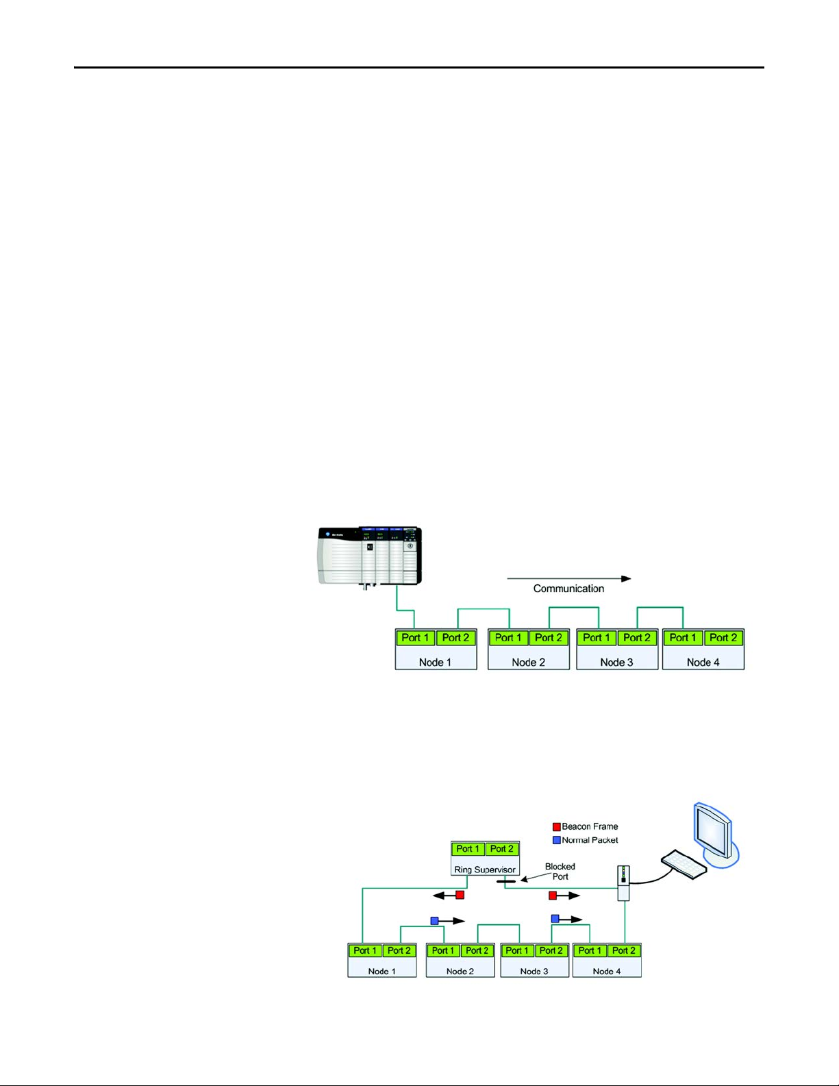
Embedded dual port switch — ArmorStart LT EtherNet/IP version includes a
dual port 10/100 mb/s ethernet switch that supports linear or Device Level Ring
(DLR) topology.
Figure 1 - Linear Topology
Device Level Ring (DLR) - ArmorStart LT EtherNet/IP version offers DLR
support with beacon frame performance. DLR provides a single fault tolerant
network solution for EtherNet/IP.
Figure 2 - DLR with Beacon Performance — No Fault
20 Rockwell Automation Publication 290E-UM001B-EN-P - June 2012
Page 21
Product Overview Chapter 1
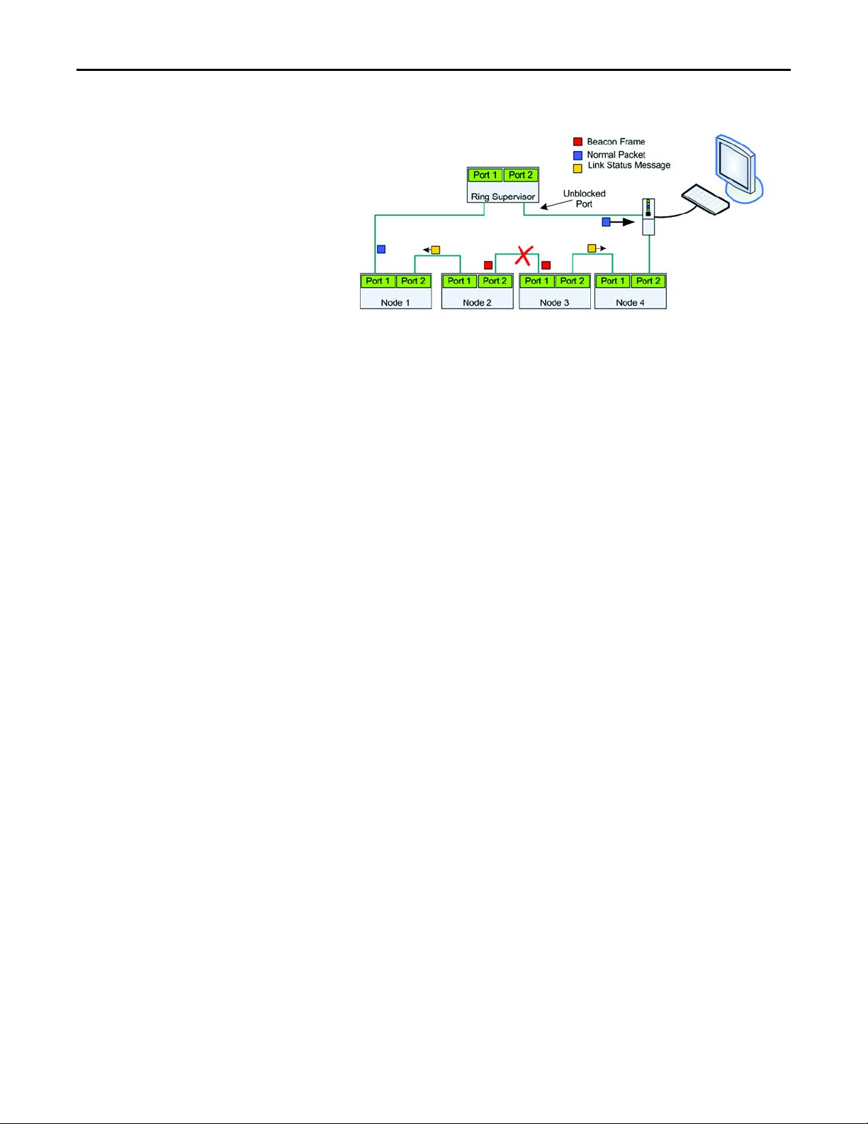
Figure 3 - DLR with Beacon Performance — Fault
In this example the fault is precisely identified by the link status message and the supervisor opens the blocked port to
allow network traffic to continue normally.
IEEE 1588 transparent clock —ArmorStart LT EtherNet/IP version supports
the IEEE 1588 transparent clock when used with precision time protocols
(PTP). A transparent clock measures and adjusts for packet delays, therefore
removing the negative effects that these variations can cause within a
synchronized distributed network of devices.
Embedded web server — ArmorStart LT EtherNet/IP version offers a web
server that can be accessed via a standard internet browser. The web server
provides status, diagnostics, and configuration capabilities.
E-mail notification — ArmorStart LT via the embedded web server, supports
configuration of the Simple Mail Transfer Protocol (SMTP). Once properly
configured, the motor controller will e-mail the user with specific fault/trip
messages.
Rockwell Automation Publication 290E-UM001B-EN-P - June 2012 21
Page 22

Chapter 1 Product Overview
Factory-Installed Options
Internal power supply (IPS) — ArmorStart LT offers the user an optional
24V DC internal power supply. The internal power supply provides all control
and I/O power needs and is sourced from the incoming 3-phase power. This
eliminates the need to run separate control power to each unit, reducing
installation time and cost. The local at-motor disconnect will remove power
from the motor terminals and outputs when in the OFF condition.
Hand/Off/Auto (HOA) keypad — ArmorStart LT offers an optional local
Hand-Off-Auto keypad. This key pad allows local start/stop motor control
regardless of PLC status. This option can be used for troubleshooting or
maintenance operations. The HOA can also be disabled when local control
is not allowed, using parameter 67.
Source brake — ArmorStart LT provides an optional, internally-controlled
electromechanical motor brake contactor. The motor brake power is sourced
from 3-phase power, L1 and L2.
Quick disconnect gland — ArmorStart LT offers a plug -n- play solution that
simplifies wiring and installation. These factory installed quick disconnect
receptacles provide connectivity to ArmorConnect® media for three-phase,
control, and motor connections. The cables are ordered separately.
22 Rockwell Automation Publication 290E-UM001B-EN-P - June 2012
Page 23
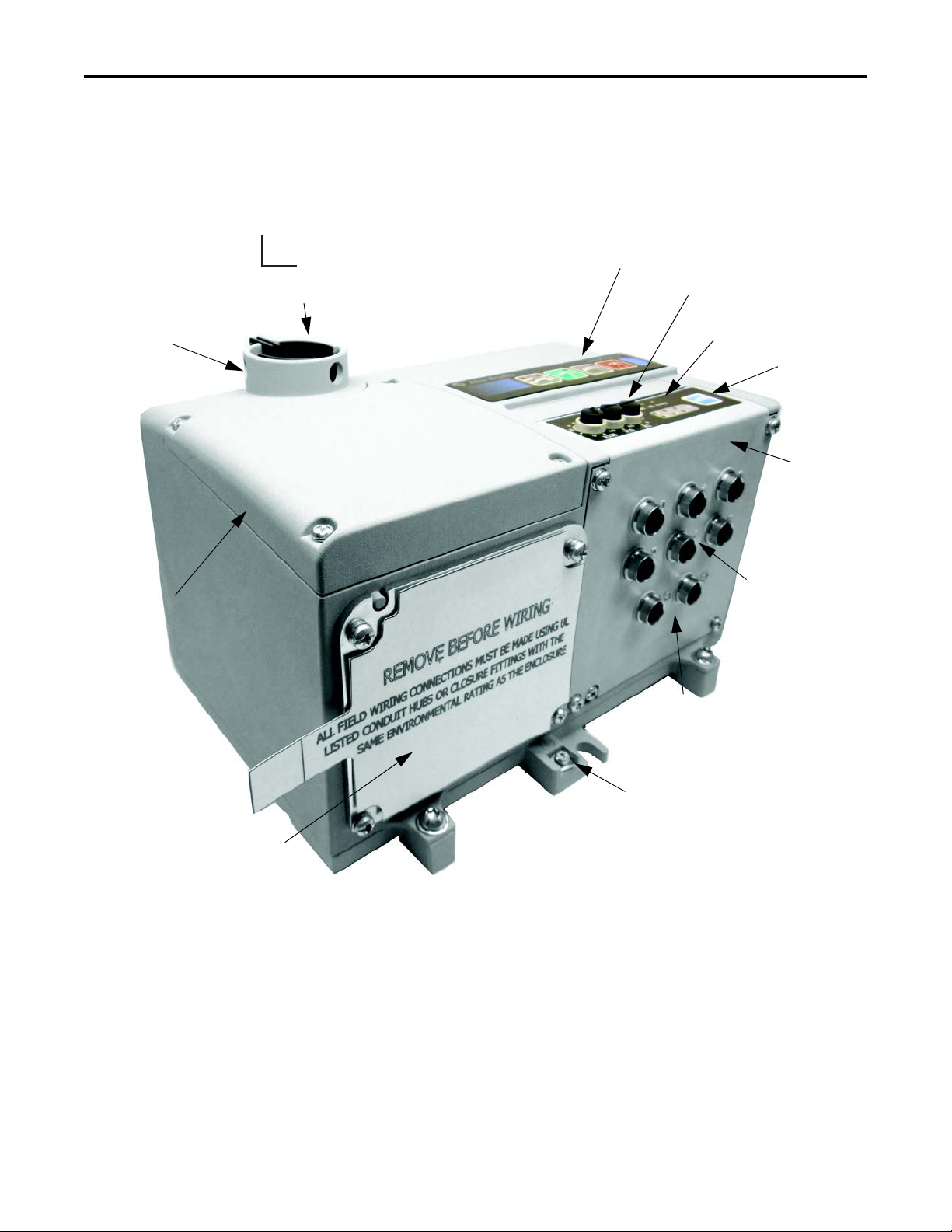
ArmorStart LT Characteristics
6 Configurable I/Os
LockOut/TagOut Provision
Wiring A ccess
Reset
IP Address Switches
On/Off Switch
HOA Keypad (optional)
Gland Plate – Conduit/Cord Grip or
ArmorConnect® Media (optional)
Status and Diagnostic LEDs
Dual Port EtherNet/IP
(This is replaced by a DeviceNet connector,
when DeviceNet communication is selected)
ECM (Electronic
Control Module)
Protective Earth (PE)
0
O
1
On
Product Overview Chapter 1
Figure 4 - Bulletin 290E/291E ArmorStart LT
Rockwell Automation Publication 290E-UM001B-EN-P - June 2012 23
Page 24

Chapter 1 Product Overview
Catalog Number Explanation
Examples given in this section are for reference purposes. This basic explanation
should not be used for product selection; not all combinations will produce a
valid catalog number.
290 E - F A Z - G1 - Option 1 - Option 2
—————— —— ——
abcde f g h
a
Bulletin Number
Code Description
290 Full-Voltage Starter
291 Reversing Starter
b
Communications
Code Description
E EtherNet/IP
D DeviceNet
Code D escrip tion
Z External 24V DC control power
PInternal power supply
Code D escrip tion
G1 Conduit entry
G2 ArmorConnect
G3 Gland Kits ➋
e
Control Voltag e
f
Gland Plate Options
(Power and Motor)
c
Enclosure Type
Code Description
F UL Type 4/12 ➊
Code D escrip tion
3 Hand/Off/Auto selector keypad
3FR Hand/Off/Auto selector keypad with
d
Overload Selection
Code Description
A 0.25…3.5 A
B 1.1…7.6 A
Code Desc ription
blank
➌
➊ IP66/UL Type 4 is available with all gland options. UL Type 4/12 is available with G1 and G3 gland option.
➋ See selection guide 290-SG001_-EN-P Accessories section for gland configurations and ordering.
➌ Leave blank unless there is a customer-specific option defined by th e factory.
g
Option 1
Forw ard/Reve rse
h
Option 2
No option
24 Rockwell Automation Publication 290E-UM001B-EN-P - June 2012
Page 25
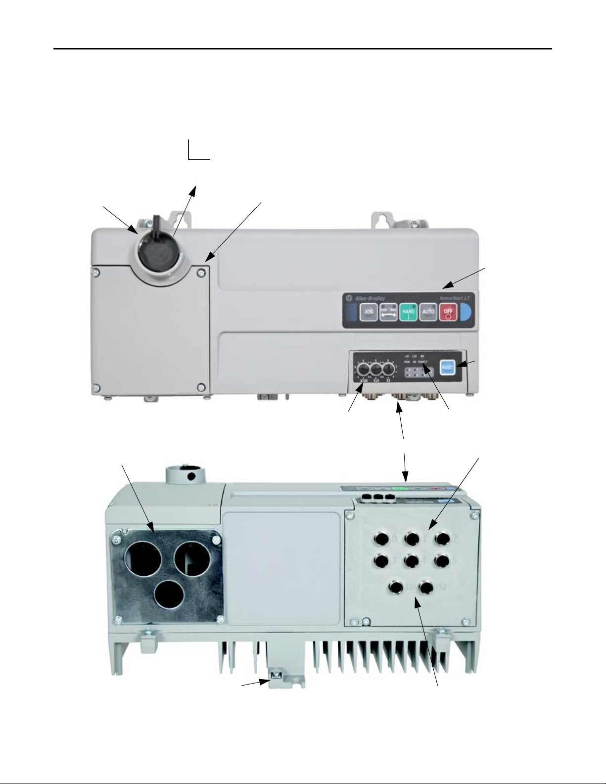
ArmorStart LT Characteristics
Bottom View
1
On
0
O
Protective Earth (PE)
Dual Port EtherNet/IP
(This is replaced by a DeviceNet connector,
when DeviceNet communication is selected)
LockOut/TagOut Provision
Gland Plate – Conduit/Cord Grip or
ArmorConnect Media (optional)
Reset
IP Address Switches
ECM (Electronic Control Module)
Hand-Off-Auto
Keypad ( optional)
On/Off Switch
Status and Diagnostic LEDs
Wiri ng Acces s
6 Configurable I/Os
Product Overview Chapter 1
Figure 5 - Bulletin 294E ArmorStart LT
Rockwell Automation Publication 290E-UM001B-EN-P - June 2012 25
Page 26

Chapter 1 Product Overview
Catalog Number Explanation
Examples given in this section are for reference purposes. This basic explanation
should not be used for product selection; not all combinations will produce a
valid catalog number.
294 E - F D1P5 Z - G1 - Option 1 - Option 2
——————————
abc d ef g h
a
Bulletin Number
Code Description
294 VFD Starter
b
Communications
Code Description
E EtherNet/IP
D DeviceNet
Code D escrip tion
Z External 24V DC control power
PInternal power supply
Code D escrip tion
G1 Conduit entry
G2 ArmorConnect
G3 Gland kits ➋
e
Control Voltag e
f
Gland Plate Options
(Power and Motor)
c
Enclosure Type
Code Description
F UL Type 4/12 ➊
Code D escrip tion
3 Hand/Off/Auto selector keypad with Jog
d
Output Current
Code Description
D1P5 1.5 A (0.4 kW), 0.5 Hp
D2P5 2.5 A (0.75 kW), 1.0Hp
D4P2 3.6 A (1.5 kW), 2.0Hp
Code Desc ription
SB S ource Brake
blank
➌
➊ IP66/UL Type 4 is available with all gland options. UL Type 4/12 is available with G1 and G3 gland option.
➋ See selection guide 290-SG001_-EN-P Accessories section for gland configurations and ordering.
➌ Leave blank unless there is a customer-specific option d efined by the factory.
g
Option 1
function
h
Option 2
No option
26 Rockwell Automation Publication 290E-UM001B-EN-P - June 2012
Page 27
Product Overview Chapter 1
Outputs
Inputs
EtherNet
Comms
A3
A1
A2
O
Switched Control Power
Unswitched Control Power
Motor
Control
Motor
Controller
Class 2
External
24VDC Power
Supply
Disconnect
24VDC
+
-
L1 L2
L3
T1 T2
T3
* Control power output is determined by disconnect status
*
ArmorStart LT
L
N
Basic Operation
Group Motor Installations for USA and Canada Markets
The ArmorStart LT Distributed Motor controllers are listed for use with each
other in group installations per NFPA 79, Electrical Standard for Industrial
Machinery and NFPA 70, the National Electrical Code. When applied according
to the group motor installation requirements, two or more motors are permitted
on a single branch circuit. Group Motor Installation has been successfully used
for many years in the USA and Canada.
Note: For additional information regarding group motor installations with the
ArmorStart LT Distributed Motor Controller, see Appendix A
.
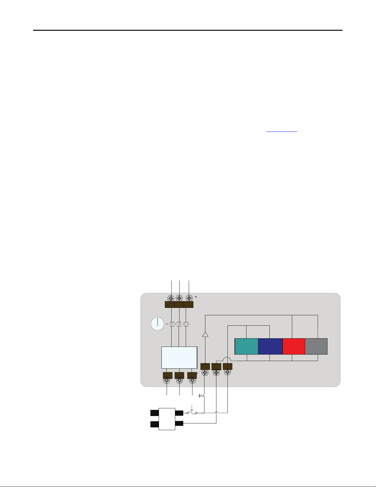
Control Circuit
ArmorStart LT accepts a 24V DC Class 2 input power supply for switched
and unswitched power. The control voltage provides power to the inputs
(unswitched) and outputs (switched). Unswitched control voltage is used to
ensure no loss of network connectivity, sensor, or other field input status under
normal operation. The control power terminal connections are labeled A1, A2,
and A3. Switched power is identified as (+A1) (-A2). Unswitched power is
identified as (+A3) (-A2).
As an option, ArmorStart LT can be supplied with an internal power supply
(IPS) eliminating the need for an external control power. The IPS is sourced
from the line side of 3-phase power and is not impacted by the status of the local
at-motor disconnect switch.
Figure 6 - Control Circuit Wiring Diagram — Single External Power Supply
Rockwell Automation Publication 290E-UM001B-EN-P - June 2012 27
Page 28
Chapter 1 Product Overview
Outputs
Inputs
EtherNet
Comms
A3
A1
A2
O
Switched Control Power
Unswitched Control Power
Motor
Control
Motor
Controller
Class 2
External Switched
24VDC Power Supply
Disconnect
24VDC
+
-
L
N
L1 L2
L3
24VDC
+
-
L
N
Class 2
External Unswitched
24VDC Power Supply
* Control power output is determined by disconnect status
*
T1 T2
T3
ArmorStart LT
Outputs
Inputs
EtherNet
Comms
O
Motor
Control
Motor
Controller
Disconnect
Internal Power
Supply
*
* Control power output is determined by disconnect status
T1 T2
T3
ArmorStart LT
*
L2L3L1
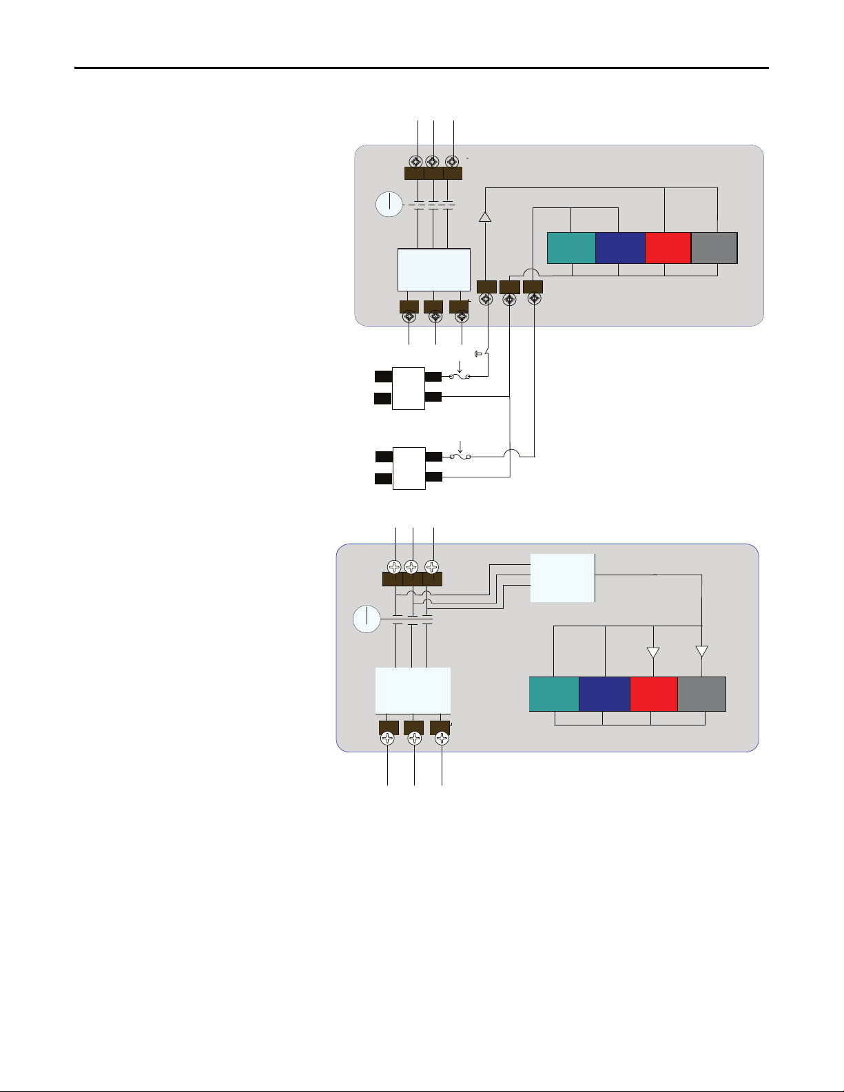
Figure 7 - Control Circuit Wiring Diagram — Multiple External Power Supplies
Figure 8 - Control Circuit Wiring Diagram — Internal Power Supply (optional)
28 Rockwell Automation Publication 290E-UM001B-EN-P - June 2012
Page 29
Product Overview Chapter 1
Motor Circuit
The ArmorStart LT Distributed Motor Controllers are rated to operate the
following types of three-phase squirrel-cage induction motors:
Bulletin 290E/291E:
0.5 Hp (0.37 kW) to 5 Hp (3 kW) @ 480/277V AC
Bulletin 294E:
0.5 Hp (0.37 kW) to 2 Hp (1.5 kW) @ 480/277V AC
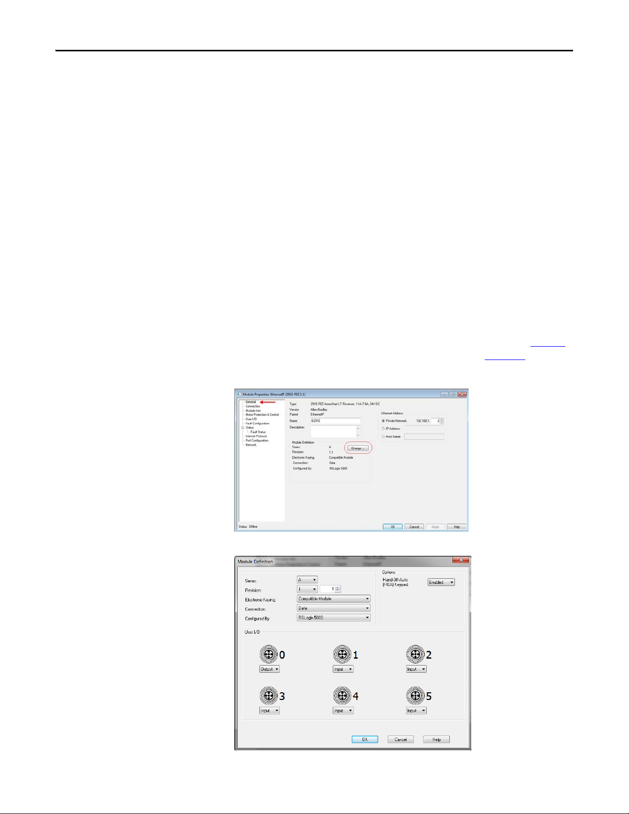
Local I/O
The ArmorStart LT provides as standard, 6 user configurable I/O points. By
default, all points are configured as an Input. When not using the AOP, the
user will need to refer to parameter 49 [IOPointConfiguration], to define an
output point.
When using the AOP, the I/O point is configured from the General screen
in the Module Definition section by clicking the “Change” button, see Figure 9
This allows user to view and configure the I/O mix, refer to Figure 10
.
.
Figure 9 - Defining I/O Point
Figure 10 - Current I/O Point Configuration
Rockwell Automation Publication 290E-UM001B-EN-P - June 2012 29
Page 30

Chapter 1 Product Overview
100%
Percent
Voltage
Time (seconds)
Overload Protection
The ArmorStart LT Distributed Motor Controller incorporates, as standard,
electronic motor overload protection. This overload protection is accomplished
2
electronically with an I
programmable via the communication network, providing the user with greater
flexibility.
The Bulletin 290E/291E includes programmable overload Class 10, 15, and 20
protection. The Bulletin 294E provides overload protection: 150% for 60s and
200% for 3s.
t algorithm. The ArmorStart LT’s overload protection is
Mode of Operation Bulletin 290E/291E
Refer to Chapter 6
, Specifications, for additional information.
Full-Voltage Start
This method is used in applications requiring across-the-line starting, in which
full inrush current and locked-rotor torque are realized. The ArmorStart LT
Bulletin 290E offers full-voltage starting and Bulletin 291E offers full-voltage
starting for reversing applications, from 0.5 Hp (0.37 kW) to 5 Hp (3 kW) at
480Y/277V AC, 3-phase power.
Figure 11 - Full-Voltage Start
30 Rockwell Automation Publication 290E-UM001B-EN-P - June 2012
Page 31

Product Overview Chapter 1
Mode of Operation Bulletin 294E
Sensorless Vector Performance
Using a distributed AC drive to operate mechanical equipment at optimum
speed helps reduce energy costs and eliminates mechanical wear and tear that can
occur in the mechanical parts. The advance monitoring found in ArmorStart LT
protects critical equipment against unplanned downtime with advanced
diagnostics and notification of irregular operating parameters. ArmorStart LT
provides open-loop speed regulation (V/Hz) with slip compensation. This
provides excellent speed regulation and high levels of torque across the entire
speed range of the drive, and improved speed regulation as loading increases.
Open Loop Speed Regulation with Slip Compensation allows the VFD to
automatically adjust the output frequency to compensate for speed changes due
to motor loading. This feature utilizes an open loop, current feedback, slip
compensation circuit. Slip Compensation works as an open loop speed regulator
that increases the output frequency of the drive as the load is increased, or
decreases the frequency as the load drops. This feature is used where the motor
must run at a relatively constant speed regardless of torque output.
% of speed
100
99
With Slip
Compensation
98
97
96
95
0 102030405060708090100
% of load
Without Slip
Compensation
Rockwell Automation Publication 290E-UM001B-EN-P - June 2012 31
Page 32

Chapter 1 Product Overview
Status LEDs and Reset
Indicator Description Color_1 Color_2
PWR LED The bicolor (green/yellow) LED shows the
RUN/FLT LED The bicolor (green/red) LED combines the
NS – Network Status
LED
LS1 and LS2 – Link
Status LEDs
MS – Module Status
LED
I/O Status
Enunciators 0…5
LEDs
Reset Button The blue reset button will cause a
Figure 12 - Status, Diagnostic LEDs, and Reset
ArmorStart LT provides comprehensive status and diagnostics via 12 individually
marked LEDs shown in Figure 12
local reset is provide for clearing of faults. Ta b l e 5
status LEDs.
Table 5 - ArmorStart LT Status and Diagnostics Indicators
state of the control voltage. When LED is
off, switched and/or unswitched power is
not present.
functions of the Run and Fault LEDs.
The bicolor (green/red) LED indicates the
status of the CIP network connection. See
Network Status Indicator for further
information.
Flashing bicolor (red/green) indicates a
self-test on power up.
The bicolor (green/yellow) LED shows the
activity/link status of each EtherNet/IP
port.
The bicolor (green/red) LED indicates the
status of the module.
Flashing bicolor (red/green) indicates a
self-test on power up.
Six yellow LEDs are numbered 0…5 and
indicate the status of the input/output
connectors. One LED for each I/O point.
protection fault reset to occur.
, located on the ECM module. In addition, a
Solid green is illuminated when switched
and unswitched control power is within its
specified limits and has the proper polarity.
Solid green is illuminated when a Run
command is present.
Flashing green indicates an IP address is
configured, no CIP connections are
established, and an Exclusive Owner
connection has not timed out.
Steady green indicates at least one CIP
connection is established and an Exclusive
Owner connection has not timed out.
Solid green is illuminated when a link has
been established at 100 Mbps.
Flashing green indicates the device has not
been configured.
Steady green indicates the device is
configured and operational.
Yellow is illuminated when input is valid or
output is on.
——
details the diagnostic and
Solid yellow is illuminated when switched
or unswitched control power is outside its
specified limits or has incorrect polarity.
The LED will blink red in a prescribed fault
pattern when a protection fault (trip)
condition is present. See Tab le 6 for fault
blink patterns.
Flashing red indicates the connection has
timed out. Steady Red indicates a duplicate
IP Address detected.
Solid yellow is illuminated when a link has
been established at 10 Mbps.
Flashing red indicates a resettable
protection fault exists or the node address
switches have been changed without a
power cycle and do not match the in-use
configuration.
Steady red indicates a non-resettable
protection fault exists.
Off when input is not valid or the output is
not turned on.
32 Rockwell Automation Publication 290E-UM001B-EN-P - June 2012
Page 33

Product Overview Chapter 1
Electronic Data Sheet (EDS)
ArmorStart LT EtherNet/IP has an embedded electronic data sheet. An EDS
consists of specially formatted text files, as defined by the CIP™. EDS files contain
details about the readable and configurable parameters of the EtherNet/IP
device. They also provide information about the I/O connections that the device
supports and the content of the associated data structures. EDS are used by
EtherNet/IP device configuration tools, such as RSNetWorx™ for EtherNet/IP,
and data servers such as RSLinx® Classic.
EDS files for all ArmorStart LT EtherNet/IP devices can be uploaded directly
from the device via the web server interface. Rockwell Automation product EDS
files are also available on the internet at: http://www.ab.com/networks/eds
.
Rockwell Automation Publication 290E-UM001B-EN-P - June 2012 33
Page 34

Chapter 1 Product Overview
Fault Diagnostics
Fault diagnostics capabilities built in the ArmorStart LT Distributed Motor
Controller are designed to help you pinpoint a problem for easy troubleshooting
and quick re-starting.
Protection Faults
Protection faults will be generated when potentially dangerous or damaging
conditions are detected. Protection faults are also known as “trips” or “faults”.
These faults will be reported in multiple formats, including:
• Bit enumeration in the TripStatus parameter 16 in DeviceLogix
• In the ArmorStart LT web server for ArmorStart EtherNet/IP version
• As a sequence of LED flashes on the ECM
Table 6 - Protection Faults
LED Flash Bit Enumeration Bulletin 290E/291E Trip Status Bits Bulletin 294E Trip Status Bits
10OverloadTrip ➊ OverloadTrip ➊
2 1 PhaseLossTrip PhaseLShortTrip
32UnderPowerTrip ➊ UnderPowerTrip ➊
4 3 SensorShor tTrip ➊ SensorShortTrip ➊
5 4 PhaseImbalTrip OverCurrentTrip
65NonVolMemoryTrip ➊ NonVolMemoryTrip ➊
76reserved ParamSyncTrip ➊
8 7 JamTrip DCBusOrDiscnnct ➊
98StallTrip StallTrip ➊
10 9 U nderloadTr ip OverTemperature ➊
11 10 reserved GroundFault ➊
12 11 reserved RestartRetries
13 12 reserved DriveHdwFault ➊
14 13 OutputShortTrip ➊ OutputShortTrip ➊
15 14 UserDefinedTrip UserDefinedTrip
16 15 HardwareFltTrip ➊ Hardwa reFltTrip ➊
➊ Cannot be disabled.
34 Rockwell Automation Publication 290E-UM001B-EN-P - June 2012
Page 35

Product Overview Chapter 1
Optional HOA Selector Keypad
Keypad Local Control
The HOA Selector Keypad allows for local start/stop/jog control in forward/
reverse motor direction. If two buttons are pressed simultaneously, this action is
ignored by the device unless one of the buttons is the OFF button. If the OFF
button is pressed at any time, the unit will go to the off state. When local Hand
mode is entered, speed reference is switched to Internal Frequency. When in
“Auto” mode the unit the speed reference is switched to the mode specified in
parameter 33 “SpeedReference”.
HAND The Hand key will initiate starter operation
AUTO
OFF If the starter is running, pressing the OFF key will cause the starter to stop.
DIR Arrow The Dir arrow selects the direction of the motor, either forward or reverse.
JOG
The Auto key allows for Start/Stop control via the communications
network
When pressed, JOG will be initiated if no other control devices are sending
a stop command. Releasing the key will cause the drive to stop, using
selected stop mode.
Optional HOA Keypad Configuration (Bulletin 290E/291E only)
The ArmorStart LT offers optional factory-installed Hand/OFF/Auto (HOA)
configurations: Standard (Bulletin 290E) and Forward/Reverse (Bulletin 291E).
Figure 13 - Bulletin 290E Standard HOA
Figure 14 - Bulletin 291 Forward/Reverse HOA
E
Rockwell Automation Publication 290E-UM001B-EN-P - June 2012 35
Page 36

Chapter 1 Product Overview
Bulletin 290E
With the KeypadMode parameter (parameter 66) set to 1 = Maintained, pressing
the buttons reacts like a maintained switch.
Current Mode
Key Press
AUTO Auto Mode — Motor Off — —
HAND If no fault, Motor On — —
OFF — Motor turns Off Motor turns Off
FAULT PRESENT — Motor turns Off Motor turns Off
With the KeypadMode parameter (parameter 66) set to 0 = Momentary,
pressing the buttons reacts like a momentary switch.
Key Press
NO KEY PRESSED — Motor Off —
AUTO Auto Mode — Motor Off — —
HAND If no fault, Motor On — —
OFF — Motor Off Motor Off
PROTECTION FAULT PRESENT — Motor Off —
OFF HAND AUTO
Current Mode
OFF Key HAND AUTO Key
Bulletin 291E
With the KeypadMode parameter (parameter 66) set to 1 = Maintained, pressing
the buttons reacts like a maintained switch.
Current Mode
Key Press
FWD/REV FWD LED Set REV LED
AUTO Auto Mode — Motor Off — —
HAND If no fault, Motor On — —
OFF Ignore Motor Off Motor Off
PROTECTION FAULT PRESENT Ignore Motor Off —
With the KeypadMode parameter (parameter 66) set to 0 = Momentary,
pressing the buttons reacts like a momentary switch.
Key Press
NO KEY PRESSED — Motor Off —
FWD/REV FWD LED Set REV LED
AUTO Auto Mode — Motor Off — —
HAND If no fault, Motor On — —
OFF — Motor Off Motor Off
PROTECTION FAULT PRESENT — Motor Off —
OFF HAND AUTO
REV LED Set FWD LED
OFF HAND AUTO
REV LED Set FWD LED
——
Current Mode
——
36 Rockwell Automation Publication 290E-UM001B-EN-P - June 2012
Page 37

Product Overview Chapter 1
IMPORTANT
Optional HOA Selector Keypad with Jog Function (Bulletin 294E only)
The HOA Selector Keypad with Jog function allows for local start/stop control
with capabilities to jog in forward/reverse motor directions.
Figure 15 - Bulletin 294E Jog/Forward/Reverse HOA
Keypad Local Control
With the KeypadMode parameter (parameter 66) set to 1 = Maintained, pressing
the buttons reacts like a maintained switch.
Current Mode
Key Press
NO KEY PRESSED — — Motor Off —
FWD/REV FWD LED Set REV LED
JOG If no fault, Jog Motor — — —
AUTO Auto Mode — Motor O ff — — —
HAND If no fault, Motor On — — —
OFF — Motor Off Motor Off Motor Off
PROTECTION FAULT PRESENT — Motor Off Motor Off —
OFF HAND JOG AUTO
REV LED Set FWD LED
FWD LED Set REV LED
REV LED Set FWD LED
——
With the KeypadMode parameter (parameter 66) set to 0 = Momentary,
pressing the buttons reacts like a momentary switch.
Current Mode
Key Press
NO KEY PRESSED — Motor Off Motor Off —
FWD/REV FWD LED Set REV LED
JOG If no fault, Jog Motor — — —
AUTO Auto Mode — Motor O ff — — —
HAND If no fault, Motor On — — —
OFF — Motor Off Motor Off Motor Off
PROTECTION FAULT PRESENT — Motor Off Motor Off —
OFF HAND JOG AUTO
REV LED Set FWD LED
FWD LED Set REV LED
REV LED Set FWD LED
——
If multiple buttons are pressed at the same time, the software interprets this as
a “no button pressed” condition. The only exception to this rule is if multiple
buttons are pressed and one of them is the OFF button. If the OFF button is
pressed in combination with any combination of other buttons, the processor
will behave as if the OFF button were pressed by itself.
Rockwell Automation Publication 290E-UM001B-EN-P - June 2012 37
Page 38

Chapter 1 Product Overview
Keypad Disable Parameter
“Keypad Disable”, parameter 67, only inhibits the “HAND”, “FWD”, “REV” and
“JOG” buttons on the HOA keypad. The “OFF” and “AUTO” buttons are
always enabled, even if parameter 67 is set to “1=Disable”. The keypad OFF
button can not be disabled.
Source Brake Contactor and Connector (Bulletin 294E only)
An internal contactor is used to switch the electromechanical motor brake
On/Off. The motor brake contactor is actuated via the internal power which
supplies L1 and L2 voltage to the mechanical brake in the motor. The source
brake can be configured for independent control via parameter configuration.
The internal contactor, electromechanical motor brake, and associated motor
branch cable are protected by the branch circuit protective device. There is no
resettable or replaceable protective device in ArmorStart LT.
WARNING: If the branch circuit protective device trips, the user must ensure
that the Source Brake function is still operational prior to putting the
equipment back in service. If the source brake function is not working properly,
loss of brake function or motor damage can occur.
38 Rockwell Automation Publication 290E-UM001B-EN-P - June 2012
Page 39

Installation and Wiring
IMPORTANT
Chapter 2
Receiving
Unpacking
It is the responsibility of the user to thoroughly inspect the equipment before
accepting the shipment from the freight company. Check the item(s) received
against the purchase order. If any items are damaged, it is the responsibility of the
user not to accept delivery until the freight agent has noted the damage on the
freight bill. Should any concealed damage be found during unpacking, it is also
the responsibility of the user to notify the freight agent. The shipping container
must be left intact and the freight agent should be requested to make a visual
inspection of the equipment.
Remove all packing material, wedges, or braces from within and around the
ArmorStart LT distributed motor controller and other device(s). Check the
contents of the package to see if all contents are included. Contact your local
Allen-Bradley representative if any items are missing.
Before the installation and start-up of the drive, a general inspection
of mechanical integrity (i.e. loose parts, wires, connections, packing
materials, etc.) must be made.
Inspecting
Storing
After unpacking, check nameplate catalog number(s) of the item(s) against the
purchase order. See Chapter 1
which will aid in nameplate interpretation.
The controller should remain in the shipping container prior to installation.
If the equipment is not to be used for a period of time, it must be stored according
to the following instructions in order to maintain warranty coverage.
• Store in a clean, dry location.
• Store within an ambient temperature range of –25…+85°C
(–13…+185°F).
• Store within a relative humidity range of 0…95%, noncondensing.
• Do not store equipment where it could be exposed to a corrosive
atmosphere.
• Do not store equipment in a construction area.
Rockwell Automation Publication 290E-UM001B-EN-P - June 2012 39
for an explanation of the catalog numbering system
Page 40

Chapter 2 Installation and Wiring
Installation Precautions
Precautions for Bulletin 290E/291E Applications
The following statements must be read and understood.
ATTENTION: The earth ground terminal shall be connected to a solid earth
ground via a low-impedance connection.
ATTENTION: Copper ground conductors are recommended. The ArmorStart LT
external protective earth (PE) pad is aluminum. Refer to your local electrical
installation standard for proper bonding and protection when dissimilar metals
are used.
ATTENTION: An incorrectly applied or installed controller can damage
components or reduce product life. Wiring or application errors, such as
undersizing the motor, incorrect or inadequate AC supply, or out of range
ambient temperatures, may result in malfunction of the system.
SHOCK HAZARD: To prevent electrical shock, open appropriate machine
disconnect switch prior to connecting and disconnecting cables. Risk of shock —
environment rating may not be maintained with open receptacles.
Precautions for Bulletin 294E Applications
Dimensions
SHOCK HAZARD: The drive contains high voltage capacitors which take time
to discharge after removal of mains supply. Before working on drive, ensure
isolation of mains supply from line inputs (L1, L2, L3). Wait three minutes
for capacitors to discharge to safe voltage levels. Failure to do so may result
in personal injury or death.
ArmorStart LT consists of three components that are non-replaceable. The
Electronic Control Module (ECM); a gland plate for wire entry; and the
aluminum alloy enclosure which makes up the back cover, top housing, and
wiring access door. The ECM includes communications, discrete I/O, status and
diagnostic LEDs, and the node address switches. All mating surfaces are sealed
using foam in place gasket or o-ring.
40 Rockwell Automation Publication 290E-UM001B-EN-P - June 2012
Page 41

Installation and Wiring Chapter 2
Front View
Right Side View
Conduit Gland Entrance
ArmorConnect Internal Power
Supply Gland Plate (optional)
ArmorConnect Media
Gland Entrance (optional)
ArmorConnect Source Brake
Gland Plate (optional)
1 in. conduit opening
0.75 in. conduit opening
Line
Control
Motor
Line
Motor
Control
Line
Motor
Source Brake
152,65
(6.0)
48,5
(1.9)
24,25
(1.0)
38,49
(1.5)
57,13
(2.3)
37
(1.5)
260
(10.2)
130
(5.1)
166,5
(6.6)
202,05
(8.0)
65
(2.6)
170
(6.7)
217,83
(8.6)
37
(1.5)
57,13
(2.3)
24,25
(1.0)
38.49
(1.5)
48,5
(1.9)
37
(1.5)
57,13
(2.3)
38,61
(1.5)
24,25
(1.0)
37
(1.5)
57,13
(2.3)
38,49
(1.5)
48,5
(1.9)
IMPORTANT
For proper heat dissipation and product operation, mount the ArmorStart LT in the
vertical orientation as shown.
Dimensions
Dimensions are shown in millimeters (inches). Dimensions are not intended
to be used for manufacturing purposes. All dimensions are subject to change.
Figure 16 - Dimensions for Bulletin 290E/291E
Rockwell Automation Publication 290E-UM001B-EN-P - June 2012 41
Page 42

Chapter 2 Installation and Wiring
Front View
Conduit Gland Entrance - Bottom View
Right Side View
ArmorConnect Internal Power
Supply Gland Plate (optional)
ArmorConnect Media Gland
Entrance (optional)
ArmorConnect Gland Entrance
with Source Brake (optional)
1 in. conduit opening
0.75 in. conduit opening
Control
Motor
Motor
Line
Control
Motor
Line
Source Brake
Line
206,43
(8.1)
120
(4.7)
202,27
(8.0)
219,32
(8.6)
170
(6.7)
381
(15.0)
240
(9.4)
37
(1.5)
92,9
(3.7)
38.49
(1.5)
24,25
(1.0)
48,5
(1.9)
37
(1.5)
92.9
(3.7)
38,61
(1.5)
24,25
(1.0)
24,25
(1.0)
92,9
(3.7)
92,9
(3.7)
37
(1.5)
37
(1.5)
38,55
(1.5)
38,55
(1.5)
48,5
(1.9)
48,5
(1.9)
IMPORTANT
For proper heat dissipation and product operation, mount the ArmorStart LT in the
vertical orientation as shown.
Figure 17 - Dimensions for Bulletin 294E
42 Rockwell Automation Publication 290E-UM001B-EN-P - June 2012
Page 43

Installation and Wiring Chapter 2
1.00 in.
(25.4 mm)
1.00 in.
(25.4 mm)
1.00 in.
(25.4 mm)
0.75 in.
(19.05 mm)
0.75 in.
(19.05 mm)
0.75 in.
(19.05 mm)
0.75 in.
(19.05 mm)
Dia. 25.5 mm
Dia. 25.5 mm
Dia. 25.5 mm
Dia. 20.5 mm
Dia. 20.5 mm
G1 Conduit G2 Media
Standard
U.S. Trade Knock-outs
G3 Conduit
Daisy Chaining
IP66 Metric Fittings
No Internal Power Supply
No Source Brake
Source Brake
No Internal Power Supply
Internal Power Supply
No Source Brake
Internal Power Supply
and Source Brake
User Modied
Dia. 25.5 mm
Dia. 20.5 mm
Dia. 20.5 mm
Cat. No.
290-G3-A2
290-G3-A3
290-G3-A4
290-G3-A5
290-G3-A1
45°
66.1 mm
11.8 mm
10.1 mm
91.3 mm
80.7 mm
Gland Plate Clearances
Modications are not permitted in the keepout region. Fitting(s) should be oriented
so that they do not interfere with the enclosure when the gland plate is installed.
Torque the gland mounting screws to 12…14 in•lb (1.3…1.6 N•m).
Dimensions are shown in millimeters (inches). Dimensions are not intended
to be used for manufacturing purposes. All dimensions are subject to change.
Figure 18 - ArmorStart LT Gland Plate Matrix
Connection Locations
Figure 19 - Internal Power, Control, and Ground Locations
Rockwell Automation Publication 290E-UM001B-EN-P - June 2012 43
Page 44

Chapter 2 Installation and Wiring
Figure 20 - Gland Connection
Wiring Terminal Detail
44 Rockwell Automation Publication 290E-UM001B-EN-P - June 2012
The power, control, and ground wire capacity and the tightening torque
requirements are shown in Ta b l e 8
per terminal are shown in Ta b l e 7
found in the wiring area. Access can be gained by removing the terminal access
cover plate.
. The maximum number of connections
. As shown in Figure 21 all the terminals are
Page 45

Installation and Wiring Chapter 2
L2
L1
T1
L3
T2
T3
A2
A3
A1
PE
B1 B2
Wire Strip Length
0.35 ± 0.01 in.
(9 ± 0.2 mm)
Figure 21 - ArmorStart LT Power and Control Terminals
Table 7 - Power, Control, and Ground Terminal Designations
Terminal Designations Wires/Connections Description
A1 2 Switched 24V DC Control Power (+) ➊
A2 2 Control Power Common (–) ➊
A3 2 Unswitched 24V DC Control Power (+) ➊
PE 2 Ground
L1 2 Line Power – Phase A
L2 2 Line Power – Phase B
L3 2 Line Power – Phase C
T1 1 Motor Connection – Phase A
T2 1 Motor Connection – Phase B
T3 1 Motor Connection – Phase C
B1 1 Source Brake Connection – B1 ➋
B2 1 Source Brake Connection – B2 ➋
➊ When internal power supply option is selected, no connection is made here.
➋ Available only with Bulletin 294E.
Rockwell Automation Publication 290E-UM001B-EN-P - June 2012 45
Page 46

Chapter 2 Installation and Wiring
IMPORTANT
Power Terminals
Motor Terminals
Control Terminals
PE/Ground
Source Brake (Bulletin 294)
Branch Circuit Protection
Table 8 - Power, Control, and Ground Wire Capacity and the Tightening Torque Requirements
Wire Size (2) #18…#10 AWG (0.8…5.2 mm2) per terminal
Tightening Torque 10.6 +/– 2 lb•in (1.2 +/– 0.2 N•m)
Wire Size #18…#10 AWG (0.8…5.2 mm
Tightening Torque 10.6 +/– 2 lb•in (1.2 +/– 0.2 N•m)
Wire Size (2) #18…#10 AWG (0.8…5.2 mm
Tightening Torque 10.6 +/– 2 lb•in (1.2 +/– 0.2 N•m)
Wire Size (2) #16…#10 AWG (1.3…5.2 mm
Tightening Torque 18 +/– 2 lb•in (2 +/– 0.2 N•m)
Wire Size #16 …#10 AWG (1.0…4.0 mm
Tightening Torque 4.8 ± 2 lb•in (0.5 ± 0.2 N•m )
2
) per terminal
2
) per terminal
2
) per terminal
2
) per terminal
ArmorStart LT is UL Listed for use with 14 AWG wire or preassemble power
cab le. Re fer to your local el ectrica l code (s) wh en app lying 16 AWG wi re or c able
in a motor circuit.
ATT EN TI ON : Select the motor branch circuit protection that complies with the
NFPA79/ or NFPA70 (NEC) and any other governing regional or local codes.
The ArmorStart LT is Underwriters Laboratory (UL) Group Motor listed. Refer
to the product Specifications
, Chapter 6 for maximum branch fuse and circuit
breaker ratings. Select the motor branch circuit protection device that complies
with NFPA70 (NEC) or NFPA79, and any other governing regional or local
codes. The installer shall observe the product nameplate markings and not apply
the ArmorStart LT where the maximum perspective short circuit current is
exceeded. The ArmorStart LT shall be applied to a solidly grounded WYE power
distribution system that does not exceed 480V AC, 60 Hz or 400V AC, 50 Hz.
WARNING: Do not install the ArmorStart LT where the maximum available
fault current exceeds the product rating.
46 Rockwell Automation Publication 290E-UM001B-EN-P - June 2012
Page 47

Installation and Wiring Chapter 2
Typical System Example
The primary function of ArmorStart LT is to control and protect a three-phase
squirrel cage induction motor. Three-phase power enters through terminals that
are connected to a manually operated disconnect switch. The three-phase power
may also connect internally to an optional three-phase to 24V DC power supply
(IPS). Wired in series with the disconnect is an electrically operated contactor or
a variable frequency drive. For Bulletin 294E an optional source brake contactor
may also be connected to the disconnect output terminals. The source brake
contactor is used to control an electromechanical brake physically attached to the
motor. The microcontroller and interface circuits are contained in the ECM.
The ECM also houses 6 user configurable I/O points. These six I/O points are
used for system level control and are accessible via by the communication
network or DeviceLogix.
The user has the flexibility to coordinate the appropriate safety function for their
application. ArmorStart LT does not provide a safe torque-off input. Therefore,
the safety function is configured externally from the controller and based upon
the risk assessment.
For example, the risk assessment may require a safety circuit with a high level
of performance. In this example, a safety relay with redundant safety contactors
and emergency stop function can be integrated into the machine controls.
Figure 22
Rockwell Automation supplier for additional support regarding the safety
circuit or for a risk assessment of your machinery.
below is an example of this configuration. Contact your local
Figure 22 -
Rockwell Automation Publication 290E-UM001B-EN-P - June 2012 47
Page 48

Chapter 2 Installation and Wiring
IMPORTANT
IMPORTANT
IMPORTANT
ArmorConnect Media
For greater flexibility and faster installations the user may also use
ArmorConnect media for a complete plug-n-play solution. This solution
provides plug-in style stop stations, as shown in Figure 23
. The ArmorConnect
power media offers both three-phase and control power cable cord set systems.
These include patchcords, receptacles, tees, reducers and accessories to be utilized
with the ArmorStart LT Distributed Motor Controller. This cable system allows
quick connections and reduced installation time by utilizing pre-manufactured
cable assemblies for more reliable connection of the three phase and
control power.
When specifying power media for use with the ArmorStart LT Distributed
Motor Controllers (Bulletin 290E/291E and Bulletin 294E) use only
ArmorConnect power media. The use of any other power media
will void the UL Listing of the motor controller.
Refer to your local electrical code for proper application and protection of long
length power cable to minimize physical damage and appropriate short-circuit
and ground-fault protection for the assembly.
Figure 23 - ArmorConnect Configuration Example
A single channel Stop is pictured. It is necessary to perform a risk assessment
and determine specific application requirements.
1. CAT5e Bulkhead Connector and Receptacle (Example Cat. No.:1585A-DD4JD)
2. CAT5e Patch Cord, IP67, M12 D-Code, Male Straight, Male Right Angle (Example Cat. No.: 1585D-M4TBDE-*)
3. CAT5e, Patch Cable, IP20, RJ45 Male to RJ45 Male (Example Cat. No. 1585J-M4TB-*)
4. Control Power Media Patchcords – PatchCord cable with integral female or male connector on each end (Example Cat. No.: 889N-F65GFNM-*)
5. Control Power Tees – The E-stop In Tee (Cat. No.: 898N-653ST- NKF) is used to connect to the Bulletin 800F On-Machine Stop station using
a control power media patchcord.
48 Rockwell Automation Publication 290E-UM001B-EN-P - June 2012
Page 49

Installation and Wiring Chapter 2
IMPORTANT
6. The E-stop Out tee (Cat. No.: 898N-653ES-NKF) is used with cordset or patchcord to connect to the ArmorStart Distributed Motor Controller.
7. Control Power Receptacles – Female receptacles are a panel mount connector with flying leads (Cat. No.: 888N-D65AF1-*)
8. Three-Phase Power Trunk – Patchcord cable with integral female or male connector on each end (Example Cat. No.:280-PWRM35A-M*)
9. Three-Phase Drop Cable – PatchCord cable with integral female or male connector on each end (Example Cat. No.:280-PWRM22A-M*)
10. Three-Phase Power Tees and Reducer – Tee connec ts to a single drop line to trunk with quick change connectors (Cat. No.: 280-T35)
Reducing Tee connects to a single drop line (Mini) to trunk (Quick change) connector (Cat. No.: 280-RT35)
Reducer connects from quick change male connector to mini female connector (Cat. No.: 280-RA35)
11. Three-Phase Power Receptacles – Female receptacles are a panel mount connector with flying leads (Cat. No.: 280-M35F-M1)
See the On-Machine Connectivity catalog for specific Ethernet
media components
Figure 24 - On-Machine Stop Stations
Enclosure
Type Quick Connect
Plastic
Metal 24V AC/DC 800F-1MYMQ4
ArmorConnect Cable Ratings
Knockout
Type Operator
Mini Receptacle Metric Twist to Release
Illumination
Volta ge
24V AC/DC
Contact
Configuration
1 N.C./1 N.O.
Cat. No.
800F-1YMQ4
The ArmorConnect Power Media cables are rated per UL Type TC 600V 90°C
Dry 75°C Wet, Exposed Run (ER) or MTW 600V 90°C or STOOW 105°C
600V - Canadian Standards Association (CSA) STOOW 600V FT2.
For additional information regarding ArmorConnect Power Media refer
to ArmorStart LT selection guide, publication 290-SG001_-EN-P.
Branch Circuit Protection Requirements for ArmorConnect Three-Phase Power Media
When using ArmorConnect Three-Phase Power Media, fuses or circuit breakers
may be used for the motor branch circuit ground fault protection if properly
sized and allowed by product labeling.
Circuit Breaker:
Where ArmorStart LT is used with ArmorConnect — suitable for use on a
circuit capable of delivering not more than 10000 RMS Symmetrical Amperes
Rockwell Automation Publication 290E-UM001B-EN-P - June 2012 49
Page 50

Chapter 2 Installation and Wiring
IMPORTANT
at 480Y/277 VAC maximum when protected by Cat. No.140U-D6D3-C30
circuit breaker, refer to the Specifications
WARNING: The total circuit impedance including each cable assembly's own
impedance, must be low enough to ensure any short-circuit or ground fault
current that can flow through any assembly, will be large enough to operate the
magnetic trip of the Cat. No. 140U-D63-C* circuit breaker. Refer to NFPA 70 and
NFPA 79 or your local electrical code for guidance in coordinating over current
protective devices and the circuit being protected.
, Chapter 6.
Fusing:
Where ArmorStart LT is used with ArmorConnect — suitable for use on a
circuit capable of delivering not more than 10000 RMS Symmetrical Amperes
(SCCR) at 480/277 V AC maximum when protected by 40 A CC, J, and T
class fuses, refer to the Specifications
, Chapter 6.
Electrical Wiring
ArmorStart LT EtherNet/IP utilizes 24V DC control power for communications
and I/O. The control power terminal connections are labeled A1, A2, and A3.
Switched power (A1) will supply outputs and motor control. Unswitched
power (A3) will supply logic power, communications, and sensor inputs.
EtherNet/IP is an unpowered network, therefore if device status is important,
the A3 terminal must have an unswitched power source.
50 Rockwell Automation Publication 290E-UM001B-EN-P - June 2012
Page 51

Figure 25 - Bulletin 290E Full Voltage
L1
L2
L3
A1
A2
A3
Power
Loss
Switched
(SW)
Un-
Switched
(USW)
Common
T1
T2
T3
Disconnect
State,
Voltage
Monitoring
and Power Loss
External
Inputs
External
Outputs
Internal
Outputs
Internal
Inputs
Micro
PE
At Motor
Disconnect
Disconnect Status
Overload
DOL
Power
Conditioning
Board
Sinking
Input or
Sourcing
output
6-User Congurable I/O Points
EtherNet/IP
Logic
Fwd Status
Fwd Control
Motor
Common
Sensor Voltage
1
4
2
5
3
L1
L2
L3
A1
A2
A3
Power
Loss
Switched
(SW)
Un-
Switched
(USW)
Common)
T1
T2
T3
Disconnect
State,
Voltage
Monitoring
and Power Loss
External
Inputs
External
Outputs
Internal
Outputs
Internal
Inputs
Micro
PE
At Motor
Disconnect
Disconnect Status
Overload
Reverser
Power
Conditioning
Board
1
4
2
5
3
Sinking
Input or
Sourcing
output
6-User Congurable I/O Points
EtherNet/IP
Logic
Fwd & Rev
Status
Fwd & Rev
Control
Motor
Common
Sensor Voltage
Installation and Wiring Chapter 2
Figure 26 - Bulletin 291E Full Voltage Reversing
Rockwell Automation Publication 290E-UM001B-EN-P - June 2012 51
Page 52

Chapter 2 Installation and Wiring
L1
L2
L3
A1
A2
A3
Power
Loss
Switched
(SW)
Un-
Switched
(USW)
Common)
T1
T2
T3
Disconnect
State,
Voltage
Monitoring
and Power Loss
External
Inputs
External
Outputs
Internal
Outputs
Internal
Inputs
Micro
PE
At Motor
Disconnect
Disconnect Status
Power
Conditioning
Board
1
4
2
5
3
Sinking
Input or
Sourcing
output
6-User Congurable I/O pOINTS
EtherNet/IP
Logic
Motor
L1
L2
L3
T1
T2
T3
J3
TB2
1
11
Fan
Drive
Enable
Common
Sensor Voltage
L1
L2
L3
A1
A2
A3
Power
Loss
Switched
(SW)
Un-
Switched
(USW)
Common
T1
T2
T3
Disconnect
State,
Voltage
Monitoring
and Power Loss
External
Inputs
External
Outputs
Internal
Outputs
Internal
Inputs
Micro
PE
At Motor
Disconnect
Disconnect Status
Power
Conditioning
Board
1
4
2
5
3
Sinking
Input or
Sourcing
output
6-User Congurable I/O Points
EtherNet/IP
Logic
Motor
L1
L2
L3
T1
T2
T3
J3
TB2
1
11
Fan
Drive
Enable
Common
Sensor Voltage
Brake
Brake Status
Brake
Control
B1
B2
#16 AWG Minimum
40A BCPD max
Figure 27 - Bulletin 294E VFD
Figure 28 - Bulletin 294E VFD with -SB
52 Rockwell Automation Publication 290E-UM001B-EN-P - June 2012
Page 53

Figure 29 - Bulletin 290E Full Voltage with -IPS
L1
L2
L3
T1
T2
T3
Disconnect
State,
Voltage
Monitoring
and Power Loss
External
Inputs
External
Outputs
Internal
Outputs
Internal
Inputs
Micro
PE
At Motor
Disconnect
Disconnect Status
Overload
DOL
1
4
2
5
3
Sinking
Input or
Sourcing
output
6-User Congurable I/O Points
EtherNet/IP
Logic
Fwd Status
Fwd Control
Motor
Common
Sensor Voltage
Power
Loss
1
1
2
3
4
L1
L2
L3
T1
T2
T3
Disconnect
State,
Voltage
Monitoring
and Power Loss
External
Inputs
External
Outputs
Internal
Outputs
Internal
Inputs
Micro
PE
At Motor
Disconnect
Disconnect Status
Overload
Reverser
1
4
2
5
3
Sinking
Input or
Sourcing
output
6-User Congurable I/O Points
EtherNet/IP
Logic
Fwd & Rev
Status
Fwd & Rev
Control
Motor
Common
Sensor Voltage
Power
Loss
1
2
3
4
Installation and Wiring Chapter 2
Figure 30 - Bulletin 291E Full Voltage Reversing with -IPS
Figure 31 - Bulletin 294E VFD with -IPS
Rockwell Automation Publication 290E-UM001B-EN-P - June 2012 53
Page 54

Chapter 2 Installation and Wiring
L1
L2
L3
T1
T2
T3
Disconnect
State,
Voltage
Monitoring
and Power Loss
External
Inputs
External
Outputs
Internal
Outputs
Internal
Inputs
Micro
PE
At Motor
Disconnect
Disconnect Status
1
4
2
5
3
Sinking
Input or
Sourcing
output
6-User Congurable I/O Points
EtherNet/IP
Logic
Motor
L1
L2
L3
T1
T2
T3
J3
TB2
1
11
Fan
Drive
Enable
Common
Sensor Voltage
Power
Loss
1
2
3
4
Power
Loss
1
2
3
4
L1
L2
L3
T1
T2
T3
Disconnect
State,
Voltage
Monitoring
and Power Loss
External
Inputs
External
Outputs
Internal
Outputs
Internal
Inputs
Micro
PE
At Motor
Disconnect
Disconnect Status
1
4
2
5
3
Sinking
Input or
Sourcing
output
EtherNet/IP
Logic
Motor
L1
L2
L3
T1
T2
T3
J3
TB2
1
11
Fan
Drive
Enable
Common
Sensor Voltage
Brake
Brake Status
Brake
Control
B1
B2
#16 AWG Minimum
40A BCPD max
Figure 32 - Bulletin 294E VFD with -IPS, -SB
54 Rockwell Automation Publication 290E-UM001B-EN-P - June 2012
Page 55

Installation and Wiring Chapter 2
IMPORTANT
Group Motor Installations for USA and Canada Markets
Wiring
When ArmorStart LT is applied according to group motor installation
requirements, two or more motors of any rating or controller type, are permitted
on a single branch circuit. Group Motor Installation has been successfully used
for many years in the USA and Canada.
For additional information regarding group motor installations with the
ArmorStart LT Distributed Motor Controller, see Appendix A
Cable Workmanship Guidelines
In addition to conduit and seal-tite raceway, it is acceptable to utilize cable that is
dual rated Tray Cable Exposed Runs (TC-ER) and Cord, STOOW, for power
and control wiring on ArmorStart LT installations. In the USA and Canada
installations, the following guidance is outlined by the National Electrical Code
(NEC) and National Fire Protection Association (NFPA) 79.
In industrial establishments where the conditions of maintenance and
supervision ensure that only qualified persons service the installation, and where
the exposed cable is continuously supported and protected against physical
damage using mechanical protection, such as struts, angles, or channels, Type TC
tray cable that complies with the crush and impact requirements of Type MC
(Metal Clad) cable and is identified for such use with the marking Type TC-ER
(Exposed Run)➊ shall be permitted between a cable tray and the utilization
equipment or device as open wiring. The cable shall be secured at intervals
not exceeding 6 ft (1.8 m) and installed in a “good workman-like” manner.
Equipment grounding for the utilization equipment shall be provided
by an equipment grounding conductor within the cable.
While the ArmorStart LT is intended for installation in factory floor
environments of industrial establishments, the following must be taken into
consideration when locating the ArmorStart LT in the application:
• Cables, including those for control voltage including 24V DC and
communications, are not to be exposed to an operator or building traffic
on a continuous basis.
• Location of the ArmorStart LT to minimize exposure to continual traffic
is recommended. If location to minimize traffic flow is unavoidable, other
barriers to minimize inadvertent exposure to the cabling should be
considered.
• Routing cables should be done in such a manner to minimize inadvertent
exposure and/or damage.
• If conduit or other raceways are not used, it is recommended that strain
relief fittings be utilized when installing the cables for the control and
power wiring through the conduit openings.
➊ Historically cable meeting these crush and impact requirements was designated and marked “Open Wiring.” Cable so marked is
equivalent to the present Type TC-ER and can be used.
Rockwell Automation Publication 290E-UM001B-EN-P - June 2012 55
Page 56

Chapter 2 Installation and Wiring
Service Space
The working space around the ArmorStart LT can be minimized as the
ArmorStart LT does not require examination, adjustment, servicing or
maintenance while energized. In lieu of this service, the ArmorStart LT
is meant to be unplugged and replaced after proper lock-out/tag-out
procedures have been employed.
Hand Operation (HOA) Considerations
The Hand/Off/Auto (HOA) is a factory-installed option that the user may
select. The HOA keypad may require the ArmorStart LT to be installed as
follows, if the application requires frequent use of the hand operated interface
by the equipment operator:
1. Install not less than 2 ft (0.6 m) above the servicing level and within easy
reach of the operator, who is in a normal working position.
2. Install where the operator is not placed in a hazardous situation when
operating the equipment.
General Wiring Considerations
3. Install where the possibility of inadvertent operation is minimized.
Where inadvertent operation may cause adverse effects the HOA can be disabled
via parameter 67.
Wire in an industrial control application can be divided into three groups: power,
control, and signal. The following recommendations for physical separation
between these groups is provided to reduce the coupling effect:
• Minimum spacing between different wire groups in the same tray should
be 6 in. (16 cm).
• Wire runs outside an enclosure should be run in conduit or have shielding/
armor with equivalent attenuation.
• Different wire groups should be run in separate conduits.
• Minimum spacing between conduits containing different wire groups
should be 3 in. (8 cm).
• Minimum spacing between 3-phase power cabling and Ethernet
or I/O cabling should be at least 6 in. (16 cm) to avoid noise issues,
unless properly shielded.
56 Rockwell Automation Publication 290E-UM001B-EN-P - June 2012
Page 57

Installation and Wiring Chapter 2
IMPORTANT
Grounding
An effectively grounded product is one that is “intentionally connected to earth
through a ground connection or connections of sufficiently low impedance and
having sufficient current-carrying capacity to prevent the buildup of voltages
which may result in undue hazard to connected equipment or to persons” (as
defined by the US National Electric Code NFPA70, Article 100B). Grounding
is done for two basic reasons: safety (defined above) and noise containment or
reduction. While the safety ground scheme and the noise current return circuit
may sometimes share the same path and components, they should be considered
different circuits with different requirements.
Grounding Safety Grounds
The object of safety grounding is to ensure that all metalwork is at the same
ground (or Earth) potential at power frequencies. Impedance between the drive
and the building scheme ground must conform to the requirements of national
and local industrial safety regulations or electrical codes. These will vary based
on country, type of distribution system and other factors. Periodically check the
integrity of all ground connections.
General safety dictates that all metal parts are connected to earth with separate
copper wire or wires of the appropriate gauge. Most equipment has specific
provisions to connect a safety ground or PE (protective earth) directly to it.
Grounding PE or Ground
The safety ground - PE must be connected to earth ground. This point must
be connected to an adjacent building steel (girder, joist), a floor ground rod, a bus
bar or a building ground grid. Grounding points must comply with national and
local industrial safety regulations or electrical codes. Some codes may require
redundant ground paths and periodic examination of connection integrity.
To avoid electrolytic corrosion on the external earth terminal, avoid spraying
moisture directly on the terminal. When used in washdown environments
apply a sealant or other corrosion inhibitor on the external ground terminal
to minimize any negative effects of galvanic or electro-chemical corrosion.x
Ground connections should be inspected on a regular basis.
Grounding Motors
The motor frame or stator core must be connected directly to the PE connection
with a separate ground conductor. It is recommended that each motor frame be
grounded to building steel at the motor.
Rockwell Automation Publication 290E-UM001B-EN-P - June 2012 57
Page 58

Chapter 2 Installation and Wiring
Power Distribution
The type of transformer and the connection configuration feeding an
ArmorStart LT Bulletin 294E plays an important role in its performance
and safety.
Delta/Wye with Grounded Wye Neutral
Figure 33 -
Del ta/Wy e with Groun ded Wye Neutral is the most common type of
distribution system. The grounded neutral provides a direct path for common
mode current caused by the drive output.
AC Line Voltage
Line Reactor
SHOCK HAZARD: ArmorStart LT requires the use of grounded Wye
power systems.
Incoming voltage imbalances greater than 2% can cause large unequal currents
in a drive. An input line reactor may be necessary when line voltage imbalances
are greater than 2%.
In general, ArmorStart LT does not require line reactors. In most applications,
the ArmorStart LT is further away from the power distribution panel, therefore
the length of cable provides additional impedance as compared to an in-panel
solution.
Therefore, ArmorStart LT does not define a minimum line impedance
specification, and does not require a line reactor. Its design trades the external
reactor supplied by the customer for an internal fan integral to the controller.
This improves the overall life of the product. To achieve maximum electrical life
of Bulletin 294, a minimum 800 uH line reactor for the group can be applied to
extend total service life.
In addition, if line disturbance mitigation is also necessary, the ArmorStart LT is
equipped with an EMI filter and when used with a shielded motor cable reduces
the impact of the power switching components. For CE compliant installations
58 Rockwell Automation Publication 290E-UM001B-EN-P - June 2012
Page 59

Installation and Wiring Chapter 2
refer to the recommended EMI/RFI cord grip accessory or quick disconnect
shielded motor cable. Contact your local sales representative for details.
If however, the customer specifications require input line reactors or transformers,
the recommendation is to group the ArmorStarts at the distribution panel under
one line reactor (not individual reactors or transformers). Keep in mind where
full voltage ArmorStarts are included with VFD ArmorStarts, the starting
currents of the full voltage ArmorStarts can be significant. The current must be
accounted for in the selection of the line reactor or you run the risk of nuisance
undervoltage faults of the VFD ArmorStarts while the full voltage ArmorStarts
are starting their motors.
ATT EN TI ON : For 50°C ambients ArmorStart LT must be derated and applied
with a minimum of 800 uH to1200 uH line reactor. Failure to follow this
application requirement will result in premature product failure. Contact your
local Rockwell Automation representative for assistance.
Bulletin 294 Motor Cable Considerations
The majority of recommendations regarding drive cable address issues are caused
by the nature of the drive output. A PWM drive creates AC motor current by
sending DC voltage pulses to the motor in a specific pattern. These pulses
affect the wire insulation and can be a source of electrical noise. The rise time,
amplitude, and frequency of these pulses must be considered when choosing a
wire/cable type. The choice of cable must consider:
1. The effects of the drive output once the cable is installed
2. The need for the cable to contain noise caused by the drive output
3. The amount of cable charging current available from the drive
4. Possible voltage drop (and subsequent loss of torque)
for long wire runs
Keep the motor cable lengths less than 45 ft from the ArmorStart LT.
Unshielded Cable
Properly designed multi-conductor cable can provide superior performance
in wet applications, significantly reduce voltage stress on wire insulation and
reduce cross coupling between drives.
The use of cables without shielding is generally acceptable for installations
where electrical noise created by the drive does not interfere with the operation
of other devices such as: communications cards, photoelectric switches, weigh
scales, and others. Be certain the installation does not require shielded cable
to meet specific EMC standards for CE, C-Tick or FCC. Cable specifications
depend on the installation type.
Rockwell Automation Publication 290E-UM001B-EN-P - June 2012 59
Page 60

Chapter 2 Installation and Wiring
G
R
B
W
Filler PVC Outer
Sheath
Single Ground
Conductor
Shield
Drain Wire
Figure 34 - Unshielded Multi-Conductor Cable
Shielded Cable
Shielded cable contains all of the general benefits of multi-conductor cable
with the added benefit of a copper braided shield that can contain much
of the noise generated by a typical AC Drive. Strong consideration for shielded
cable should be given for installations with sensitive equipment such as weigh
scales, capacitive proximity switches, and other devices that may be affected
by electrical noise in the distribution system. Applications with large numbers
of drives in a similar location, imposed EMC regulations, or a high degree
of communications/networking are also good candidates for shielded cable.
An acceptable shielded cable will have 4 XLPE insulated conductors with a
100% coverage foil and an 85% coverage copper braided shield (with drain wire)
surrounded by a PVC jacket.
Figure 35 - Shielded Cable with Four Conductors
W
G
R
B
Recommended Cable Connectors/Glands
Choose cable connectors or glands that offer the best cable protection, shield
termination, and ground contact.
60 Rockwell Automation Publication 290E-UM001B-EN-P - June 2012
Page 61

Installation and Wiring Chapter 2
Recommended Cord Grips
The following are recommended cord grips to be used
for ArmorStart LT installations.
Table 9 - Cord grip for Motor, Power, and Control
Recommended Thomas and Betts Cord Grips for G1 and G3 Glands.
Thomas and Betts Part Nos.
Description Gland
Motor/Source Brake G1 0.75 in. 0.500…0.750 2932NM 5263 142TB
Motor/Source Brake G1 0.75 in. 0.660…0.780 2675 5263 142TB
Power G1 1.0 in. 0.660…0.780 2676 5264 143
Power G1 1.0 in. 0.770…0.895 2677 5264 143
Control Power, Motor/Source
Brake
3-Phase Power G3 M25 0.512…0.709 CC-ISO25-G ➊ GMN-M25
➊ Contact Thomas and Betts for product selection details
Knockout
Size Cable Diameter Range (in.2)
G3 M20 0.236…0.473 CC-ISO20-G ➊ GMN-M20
Cord Grip
Sealing
Ring
Lock Nut
Shield Terminating Connectors
The cable connector selected must provide good 360o contact and low transfer
impedance from the shield or armor of the cable to the conduit entry plate at
both the motor and the ArmorStart LT for electrical bonding. SKINTOP
MS-SC/MS-SCL cable grounding connectors and NPT/PG adapters from
LAPPUSA are good examples of this type of shield terminating gland.
®
Rockwell Automation Publication 290E-UM001B-EN-P - June 2012 61
Page 62

Chapter 2 Installation and Wiring
U (T1)
V (T2)
W (T3)
PE
One or More
Ground Leads
Braid wires pulled back in a 360° pattern
around the ground cone of the connector
Drain wires pulled back in a 360° pattern
around the ground cone of the connector
Metal locknut bonds the
connector to the panel
Metal connector body
makes direct contact with
the braid wires
ATTENTION: Shielded connector or motor cable is mandatory for CE compliant
installations.
Ground Bushing
Figure 36 - Terminating the Shield with a Connector
Electromagnetic Compatibility (EMC)
The following guidelines are provided for EMC installation compliance.
General Notes (Bulletin 294E only)
• The motor cable should be kept as short as possible in order to avoid
electromagnetic emissions as well as capacitive currents. CE conformity
of ArmorStart LT with EMC directive does not guarantee the entire
machine installation complies with CE EMC requirements. Many
factors can influence total machine/installation compliance.
• The EMI filter may result in relatively high ground leakage currents.
Therefore, ArmorStart LT must only be applied in installations that are
solidly grounded (bonded) to the building power distribution ground.
62 Rockwell Automation Publication 290E-UM001B-EN-P - June 2012
Page 63

Installation and Wiring Chapter 2
Pin 1 – Drain (no connection)
Pin 2 – +VDNET
Pin 3 – -VDNET
Pin 4 – CAN_H
Pin 5– CAN_L
4
3
Ethernet/IP Connector D-coded (M12)
M12 Female Ethernet Connector
Pin 1 – Tx+
Pin 2 – Rx+
Pin 3 – Tx–
Pin 4 – Rx–
I/O Connector (M12)
Pin 1 – Sensor Source Voltage
Pin 2 – Not Used
Pin 3 – Common
Pin 4 – Input or Output
Pin 5 – Not Used
ATTENTION: RFI Filter Grounding. Due to the presence of an integral EMI
filter, this product may draw more that 3.5 mA of leakage current. The controller
must only be used in installations with grounded AC supply systems and be
permanently installed and solidly grounded (bonded) to the building power
distribution ground. Grounding should not include any form of plug or socket
that would permit inadvertent disconnection. Consult your local codes
regarding redundant ground connections and/or size of protective earthing
conductor. The integrity of all connections should be periodically checked.
Ethernet, DeviceNet, and I/O Connections
DeviceNet Connector (M18)
Rockwell Automation Publication 290E-UM001B-EN-P - June 2012 63
Page 64

Chapter 2 Installation and Wiring
Pin 1 - T1 (black)
Pin 2 - T2 (white)
Pin 3 - T3 (red)
Pin 4 - Ground (green/yellow)
Pin 1 - Ground (green/yellow)
Pin 2 - B1(black)
Pin 3 -B2 (white)
Pin 1 – (+V) Unswitched (A3/red)
Pin 2 – (–V) Common (A2/black)
Pin 3 – Not used (green)
Pin 4 – Not used (blank)
Pin 5 – (+V) Switched (A1/blue)
Pin 6 – Not used (white)
Pin 1 - L1 (black)
Pin 2 - L2 (white)
Pin 3 - L3 (red)
Pin 4 - Ground (green/yellow)
ArmorConnect Power Media Receptacles
ArmorStart LT utilizes a M22 male receptacle for power inputs and a M22
female receptacle for motor or motor brake output.
Motor Connector (optional)
Source Brake Connector (optional)
Incoming Control Power (optional) – 24V DC Only
Incoming Three-Phase Power (optional)
64 Rockwell Automation Publication 290E-UM001B-EN-P - June 2012
Page 65

Installation and Wiring Chapter 2
Optional Locking Clip
The locking clip is an optional device that can be used, if desired. The clam shell
design clips over power quick disconnect connections to limit customer access to
disconnection.
Figure 37 -
SHOCK HAZARD: DO NOT connect or disconnect power or motor connections
while power is applied to ArmorStart LT. Proper Lock-Out Tag-Out procedures
should be followed to reduced the risk of severe injury.
SHOCK HAZARD: The ArmorStart LT local disconnect will only isolate the motor
power and remove switched power when turned OFF. Power inputs must be
switched OFF properly from their respective sources before connection or
disconnection of incoming power. Proper Lock-Out Tag-Out procedures should
be followed to reduced the risk of severe injury.
Rockwell Automation Publication 290E-UM001B-EN-P - June 2012 65
Page 66

Chapter 2 Installation and Wiring
Notes:
66 Rockwell Automation Publication 290E-UM001B-EN-P - June 2012
Page 67

Product Commissioning
Class A
Class B
Class C
Net ID
Net ID
Net ID
Host ID
Host ID
Host ID
0
0
0
1 0
1 1 0
7
8
15
23
16
31
31
31
24
0
Chapter 3
IP Address
The IP address identifies each node on the IP network (or system of connected
networks). Each TCP/IP node on a network must have a unique IP address.
The IP address is 32 bits long and has a net ID part and Host ID part. Networks
are classified A, B, C, (or other). The class of the network determines how an IP
address is formatted.
Figure 38 - IP Address on the IP Network
You can distinguish the class of the IP address from the first integer in its
dotted-decimal IP address as follows:
Range of first integer Class Range of first integer Class
0…127 A 192…223 C
128…191 B 224…255 other
Each node on the same physical network must have an IP address of the same
class and must have the same net ID. Each node on the same network must have
a different Host ID thus giving it a unique IP address.
Gateway Address
The Gateway Address is the default address of a network. It provides a single
domain name and point of entry to the site. Gateways connect individual physical
networks into a system of networks.
Subnet Mask
The subnet mask is used for splitting IP networks into a series of subgroups,
or subnets. The mask is a binary pattern that is matched up with the IP address
to turn part of the Host ID address field into a field for subnets.
Rockwell Automation Publication 290E-UM001B-EN-P - June 2012 67
Page 68

Chapter 3 Product Commissioning
Configuring EtherNet/IP Address
Before using the ArmorStart LT, you may need to configure an IP address, subnet
mask, and optional Gateway address. The rotary network address switches found
on the front of the ECM, are set to 999 and DHCP is enabled as the factory
default. The network Internet Protocol (IP) address can be set one of three ways:
• Use the switches located on the module
• Use a Dynamic Host Configuration Protocol (DHCP) server, such as
Rockwell Automation BootP/DHCP
• Retrieve a static IP address from nonvolatile memory
The ArmorStart LT reads these switches first at power up or after a reset to
determine if they are set to a valid IP address between 1…254. When switches are
set to a valid number the IP address will be 192.168.1._ _ _ [switch setting].
If the switches are set to an invalid number (for example, 000 or a value greater
than 254 excluding 888), DHCP is enabled. The DHCP server will assign the
IP address and the Transport Control Protocol (TCP) parameters.
The RS Logix 5000 installation provides a BootP/DHCP server found
in the Rockwell Software Program folder. Use Rockwell Automation BootP/
DHCP server utility, version 2.3 or later, that ships with RSLogix™ 5000
or RSLinx software.
A third party DHCP server can also be used.
Manually Configure the Network Address Switches
Remove the protective caps from the rotary switches.
Figure 39 - Switches on the I/O module
Set the network address by adjusting the three rotary switches on the front
of the ECM. When the IP address switches are valid, the subnet mask will be
68 Rockwell Automation Publication 290E-UM001B-EN-P - June 2012
Page 69

Product Commissioning Chapter 3
IMPORTANT
0
00
8
6
46
46
4
2
X100
X10
X1
28
28
This example shows the
IP address set to 000 (DHCP).
255.255.255.0 and the gateway address is set to 0.0.0.0. A power cycle is required
for any new IP address to take effect when the switches are used.
ATTENTION: To avoid unintended operation, the ArmorStart LT
must be assigned a fixed IP address. If a DHCP server is used, it must
be configured to assign a fixed IP address for ArmorStart LT.
Failure to observe this precaution may result in unintended machine
motion or loss of process control.
Figure 40 - Network Address Example
Static Address Alternative
If the manual address configuration of 192.168.1.xxx is not acceptable, a static
address can be configured using the embedded web page. First configure the
switches to a valid address to access the web page. Using a common web browser
enter the address 192.168.1._ _ _ (switches). From the Administrative Settings
window select Network Configuration. Change the Ethernet Interface
Configuration to “Static” and enter the IP Address, Subnet Mask, and Default
Gateway and apply. Change the ArmorStart LT address switches to 999. The unit
will now accept the new IP address. To access the web page you will need to use
the new address in the web browser.
The switch value of 888 allows the user to reset to factory default configuration
including configuration parameters. This setting is useful in situations where the
user wishes to decommission a module or when the user wishes to commission a
previously-used module that has an unknown configuration. When the switches
are set to 888, upon the next power cycle the ArmorStart LT will return to
factory default settings and cease all communications. The Module Status LED
shall transition to blinking red and the Network Status LED shall transition
to OFF.
After reset, the user will then need to change the IP address to a valid setting and
power cycle. The purpose of this is to prevent the user from resetting the module
and then never changing the switch setting from 888.
Setting the IP address to “888” followed by a power cycle will reset the device
to its factory default configuration. To resume network communication the
address MUST
Rockwell Automation Publication 290E-UM001B-EN-P - June 2012 69
be set to DHCP or a valid IP address and power cycled again.
Page 70

Chapter 3 Product Commissioning
Using the Rockwell Automation BootP/DHCP Utility
The Rockwell Automation BootP/DHCP utility is a stand alone program that
incorporates the functionality of standard BootP/DHCP software with a user
friendly graphical interface. It is located in the Utils directory on the
RSLogix 5000 installation CD. The ArmorStart LT must have DHCP
enabled (factory default) to use the utility.
To configure your adapter using the BootP/DHCP utility, perform the following
steps:
1. Run the BootP/DHCP software.
In the BOOTP/DHCP Request History panel you will see the Ethernet
(Mac) addresses of the devices issuing requests.
Note : the Ethernet (Mac) address for a device can be found
on the product label.
Figure 41 - BOOTP/DHCP Request History Panel
2. Double-click the Ethernet (Mac) address of the device you want
to configure.
You will see the New Entry dialog with the device’s Ethernet Address
(MAC).
Figure 42 - New Entry Dialog Box
70 Rockwell Automation Publication 290E-UM001B-EN-P - June 2012
Page 71

Product Commissioning Chapter 3
3. Enter the IP Address you want to assign to the device, and click OK.
The device is added to the Relation List, displaying the Ethernet
Address (MAC) and corresponding IP Address, Hostname, and
Description (if applicable).
Figure 43 - Relation List
When the address displays in the IP Address column in the Request
History section, it signifies that the IP address assignment has been made.
4. To assign this configuration to the device, highlight the device in the
Relation List panel, and click the Disable BOOTP/DHCP button.
When power is cycled to the device, it uses the configuration you assigned
and does not issue a DHCP request.
5. To enable DHCP for a device with DHCP disabled, highlight the device
in the Relation List, and click the Enable DHCP button.
You must have an entry for the device in the Relation List
panel to re-enable DHCP.
Rockwell Automation Publication 290E-UM001B-EN-P - June 2012 71
Page 72

Chapter 3 Product Commissioning
Figure 44 - Enable DHCP Button
Save the Relation List
You can save the Relation List to use later. To save the Relation List perform the
following steps:
1. Select Save As... from the File menu.
Figure 45 - Save Relation List
You will see the Save As Dialog.
72 Rockwell Automation Publication 290E-UM001B-EN-P - June 2012
Page 73

Product Commissioning Chapter 3
Figure 46 - Save As Dialog Box
2. Select the folder you want to Save in.
3. Enter a File name for the Relation List (for example, Control System
Configuration), and click Save.
You can leave the Save as type at the default setting: Bootp
You can then open the file containing the Relation List at a later session.
When DHCP is enabled (factory default Enabled), the unit will request its
network configuration from a DHCP/BOOTP server. Any configuration
received from a DHCP server will be stored in non-volatile memory.
The unit will try to obtain the same IP address from the DHCP server. If the
server is not present (e.g., server fails to power up), the unit will use the IP address
it previously received from the server. The DHCP timeout = 30 s.
Be cautious about using an unmanaged switch to assign the IP address.
A DHCP
server typically assigns a finite lease time to the offered IP address. The possibility
exists that the ArmorStart LT would be assigned a different IP address which
would cause a stop in communication with the controller.
Rockwell Automation Publication 290E-UM001B-EN-P - June 2012 73
Page 74

Chapter 3 Product Commissioning
IMPORTANT
Embedded Web Server
The embedded web server is used to access configuration and status data.
The user should set the password to a unique value for authorized
personnel.
If the login and password are lost you will need to reset the device
to the factory defaults, which results in losing its configuration.
To access the internal web browser, open your computer’s internet browser and
enter the IP address of the desired ArmorStart LT (for example, 192.168.1.1).
Figure 47 - Internal Web Browser
From here you are able to view parameter settings, device status, and diagnostics
from multiple tab views.
74 Rockwell Automation Publication 290E-UM001B-EN-P - June 2012
Page 75

Product Commissioning Chapter 3
Network Configuration
To access the network configuration, you will be prompted to login to the
Administrative Setting.
Figure 48 - Enter Network Password
The user will be prompted to enter the default User Name (Administrator).
The factory default password is blank. The user is expected to change the
password to avoid unauthorized access.
Figure 49 - Network Configurations
From this screen you can change the Ethernet Configuration. For example
in the above image the IP address will be changed to 10.10.10.101. Choose
“APPLY Changes” for new settings to take effect.
Rockwell Automation Publication 290E-UM001B-EN-P - June 2012 75
Page 76

Chapter 3 Product Commissioning
Parameter Configuration
ArmorStart LT embedded web server provides the user the ability to view and
modify the device configuration without having to access RSLogix 5000. To view
the device configuration from the web server, select the parameters folder.
Figure 50 -
In the figure above, the Starter Setup parameters are viewed. To modify a
parameter the user will click the “Edit” button.
Figure 51 - Enter Network Password
The user will be prompted to enter the default User Name (Administrator).
The factory default password is blank. The user is expected to change the
Password to avoid unauthorized access.
E-mail Notification Configuration
ArmorStart LT internal web server will support the e-mailing of warning and
trip messages via Simple Mail Transfer Protocol (SMTP). The configuration
parameters for the SMTP Server’s IP address, user login, and port number are
configurable through the Administrative Settings page of the internal web server.
The user will configure the device name, device description, and device trip type.
76 Rockwell Automation Publication 290E-UM001B-EN-P - June 2012
Page 77

Figure 52 - E-mail Notification Configuration
IMPORTANT
E-mail triggers:
• when a trip occurs
• when a trip is cleared
• when a warning occurs
• when a warning is cleared
Product Commissioning Chapter 3
“Cleared Event” e-mails will only be sent when all events have been cleared
and if a trip event e-mail has previously been sent.
The following is an example trip e-mail:
Subject:
ArmorStart LT 291E 1.1-7.6A has detected an Overload Trip
Body: Trip Snapshot:
SnapShotL1Amps: 1.11 Amps
SnapShotL2Amps: 2.22 Amps
SnapShotL3Amps: 3.33 Amps
SnapShotAveAmps: 2.22 Amps
SnapShot%Thermal: 55%
Trip Type: Overload Trip
Trip Info: Load has drawn excessive current based on the trip
class selected.
Device Name: ArmorStart LT 291E Test Unit
Device Description:Latest AB On-Machine Offering
Device Location: Sixth Floor Comms Lab
Contact Info: Contact 1 Info: Slicia Turnbull in California
Contact 2 Info: Steve Plummer on Friday
Rockwell Automation Publication 290E-UM001B-EN-P - June 2012 77
Page 78

Chapter 3 Product Commissioning
IMPORTANT
How to Add a New Module Using the Add-On Profile
ArmorStart LT is provided with an Add-On Profile (AOP). An Add-on profile
streamlines the programming and installation by eliminating the task of
individually configuring the device tags and providing an easy to use
configuration interface. In addition, the copy and paste function allows easy
configuration of multiple ArmorStart LTs with RSLogix™ 5000 revision 17.01
or later. There is a known compatibility issue with revision 20.0. Update RSLogix
5000 to 20.1 or greater.
If your version of RSLogix 5000 does not include the AOP for ArmorStart LT, it
can be installed from http://support.rockwellautomation.com/controlflash/
LogixProfiler.asp
1. Launch RS Logix 5000
2. From the “I/O Configuration” tree add a “New Module”
78 Rockwell Automation Publication 290E-UM001B-EN-P - June 2012
Page 79

Product Commissioning Chapter 3
3. From the list of modules find the ArmorStart LT using the catalog number.
The AOP will include all options therefore the list will only display the base
catalog number.
4. The “General” page is displayed. Enter a descriptive name for the
ArmorStart LT.
5. In the “General” page enter the ArmorStart LT IP address. The “Private
Address” corresponds to the local IP address configurations using the switches.
The “IP Address” is a static address but configured from the webpage. This allows
more flexibility in defining the address. If the address is served up, use “Host
Name” field.
6. In the “General” page, select the “Change” button. From here, define what
options are available and what discrete point, if any, will need to be defined
as an output.
The “General” page of the ArmorStart LT AOP differs from many other product
AOPs. The Module definition allows the user to specify the following items:
• Electronic Keying: Module Compatibility
• Configured By: RSLogix 5000 or ArmorStart LT Embedded Web Page
• Connection Type: Data or Listen Only
Rockwell Automation Publication 290E-UM001B-EN-P - June 2012 79
Page 80

Chapter 3 Product Commissioning
IMPORTANT
• User I/O Configuration: Specify the Input or Output use for each I/O
point
• Keypad Option: Is product supplied with this option
• Electro-Mechanical Brake Option: Is product supplied with this option
The figure below is an example of the Module Definition page.
Electronic Keying
The electronic keying feature automatically compares the expected module, as
shown in the RSLogix 5000 I/O Configuration tree, to the physical module
before I/O communication begins. You can use electronic keying to help prevent
communication to a module that does not match the type and revision expected.
Typically, three keying options are available:
• Exact Match
Exact Match keying requires all keying attributes, that is, Vendor, Product
Type, Product Code (catalog number), Major Revision, and Minor
Revision, of the physical module and the module created in the software
to match precisely to establish communication.
• Compatible Keying
Compatible Keying indicates that the module determines whether to
accept or reject communication. Compatible Keying is the default setting.
• Disable Keying
Disabled Keying indicates the keying attributes are not considered when
attempting to communicate with a module.
ATTENTION: Be extremely cautious when using Disabled Keying; if used incorrectly,
this option can lead to personal injury or death, property damage, or economic loss.
Changing electronic keying selections online may cause the I/O communication
connection to the module to be disrupted and may result in a loss of data.
80 Rockwell Automation Publication 290E-UM001B-EN-P - June 2012
Page 81

Product Commissioning Chapter 3
Connections
Two Class 1 connections for I/O transfer will be supported and six Class 3
explicit connections will be supported. The Class 1 connections are:
• Data
• Listen Only
Only one Data connection is allowed. A maximum of two Listen Only
connections are supported (shared with the Data connection). This connection
type is dependent on another connection to exist. If that connection (Data) is
closed, the listen only connection shall be closed as well.
The connection sizes are:
ArmorStart Connection Type Connection S ize (in bytes)
Bulletin290E/291E
Bulletin 294E
Input 16
Output 3
Input 18
Output 6
Configured by
The ArmorStart LT may be configured via the ArmorStart LT’s web page or
RS Logix 5000. Often times, customers utilize the web interface to configure
the unit before it is ever connected to the PLC. The AOP will require the user
to specify how the ArmorStart LT is configured, once added to RS Logix 5000.
The valid options are:
• “Web Page” — The unit is configured by the ArmorStart LT’s web pages.
The AOP will NOT display any page or content of a page that allows
configuration of the unit. In this mode Connection Type will include a
“Backup” and “Restore” feature. The Backup selection will store parameter
data in the RSLogix 5000 programming file and in the PLC. The Restore
selection will allow the user to manually re-configure a replacement unit.
• “RSLogix 5000” — The unit is configured by RSLogix 5000. The AOP
controls all parameter configurations. Any change made using the webpage
will be over written by the PLC configuration. When the user changes the
“Configured By” field from “Web Page” to “RSLogix 5000”, the values
stored by the “Backup” function will be copied to the configuration
in the PLC. The “Backup/Restore” will no longer be displayed.
Rockwell Automation Publication 290E-UM001B-EN-P - June 2012 81
Page 82

Chapter 3 Product Commissioning
HOA Keypad Option
ArmorStart LT units are available with or without an HOA Keypad. The user
will specify either “Installed” or “Not Installed”. When a unit is provided without
the HOA keypad this setting should be set to “Not Installed” which removes the
keypad parameters.
Source Brake, Electro-Mechanical Brake Option
ArmorStart LT units are available with or without an electromechanical (EM)
brake. The user will select either “Installed” or “Not Installed”. When a unit is
provided without an EM brake the setting should be set to Not Installed which
removes the associated parameters.
User Configurable I/O
The ArmorStart LT I/O points may be used as either an input or an output.
The ArmorStart LT hardware does not require the user to specify a point’s actual
use as an input or output, but the AOP requires the user to specify it to assign
the correct tag name for the I/O point. When a point is configured as an input
or output the corresponding tag name is “Pt0_Data”. If a point is configured
as an output the corresponding feedback tag name is “Pt0_ReadBack”.
Using the navigation tree on the left, start configuring the ArmorStart LT with
the simplified wizard. The minimum configuration is displayed on each page.
Review each field to determine if the default setting is acceptable or modify
as appropriate for your application. Note that more advanced properties are
available using the “Advance” buttons on the screen.
82 Rockwell Automation Publication 290E-UM001B-EN-P - June 2012
Page 83

Product Commissioning Chapter 3
Once complete the new ArmorStart LT will appear in the Ethernet tree. If there
are multiple ArmorStart LTs with similar configurations, utilize the copy-paste
function and update only those parameters that change between units.
The final step is to download your project to the controller and the ArmorStart
LT. Define the path to the PLC and then download.
RSLogix 5000 Add-On Profile
The Add-On Profile (AOP) for ArmorStart LT consists of several standard pages
and multiple product specific pages for configuration within RS Logix 5000.
In addition the AOP will automatically create descriptive tag names for the input
and output assemblies.
The following table lists the available AOPs for ArmorStart LT when adding a
new module in RS Logix 5000.
Catalog Number AOP Description
290E-FAZ ArmorStart LT DOL, 0.24…3.5 A, 24V DC
290E-FBZ ArmorStart LT DOL, 1.1…7.6 A, 24V DC
291E-FAZ ArmorStart LT Reverser, 0.24…3.5 A, 24V DC
291E-FBZ ArmorStart LT Reverser, 1.1…7.6 A, 24V DC
294E-FVD1P5Z ArmorStart LT VFD, 480V AC, 0.5 Hp
294E-FVD2P5Z ArmorStart LT VFD, 480V AC, 1 Hp
294E-FVD4P2Z ArmorStart LT VFD, 480V AC, 2 Hp
290E-FAP ArmorStart LT DOL, 0.24…3.5 A, IPS
290E-FBP ArmorStart LT DOL, 1.1…7.6 A, IPS
291E-FAP ArmorStart LT Reverser, 0.24…3.5 A, IPS
291E-FBP ArmorStart LT Reverser, 1.1…7.6 A, IPS
Rockwell Automation Publication 290E-UM001B-EN-P - June 2012 83
Page 84

Chapter 3 Product Commissioning
Catalog Number AOP Description
294E-FVD1P5P ArmorStart LT VFD, 480V AC, 0.5 Hp, IPS
294E-FVD2P5P ArmorStart LT VFD, 480V AC, 1 Hp, IPS
294E-FVD4P2P ArmorStart LT VFD, 480V AC, 2 Hp, IPS
The AOP presents an organized view of parameters within groups and specific
functional pages. All of the parameters are distributed within the AOP pages.
Each page includes basic information that must be reviewed by the user.
In addition, within each page there are capabilities that can be accessed
using the advance buttons.
The AOP page below is an example of the “Advanced” button that provides the
user additional functionality.
84 Rockwell Automation Publication 290E-UM001B-EN-P - June 2012
Page 85

Product Commissioning Chapter 3
Auto-Generated Tags
After you install and configure the AOP, the controller tags are generated. The
tag names are descriptive and automatically generated. This greatly simplifies
programming. The figure below shows an example of the auto-generated tags
for ArmorStart LT
.
The following tables provide more clarification regarding the Produce and
Consume assemblies and how they correlate with the auto-generated names.
Rockwell Automation Publication 290E-UM001B-EN-P - June 2012 85
Page 86

Chapter 3 Product Commissioning
Table 10 - Default Consume Assembly for Bulletin 294E
Instance 154 “Drive Cmd” – Default Consumed Assembly for Bulletin 294 Starters
ByteBit 7Bit 6Bit 5Bit 4Bit 3Bit 2Bit 1Bit 0
0 JogReverse JogForward ResetFault RunReverse RunForward
1 Decel2 Accel2 Out05 Out04 Out03 Out02 Out01 Out00
2 CommandFreq (Low) (xxx.x Hz)
3 CommandFreq (High) (xxx.x Hz)
4 Pt07D eviceIn Pt06DeviceIn Pt05DeviceIn Pt04DeviceIn Pt03DeviceIn P t02DeviceIn Pt01DeviceIn Pt00DeviceI n
5 Pt15D eviceIn Pt14DeviceIn Pt13DeviceIn Pt12DeviceIn Pt11DeviceIn P t10DeviceIn Pt09DeviceIn Pt08DeviceI n
6 AnalogDeviceIn (low byte)
7 AnalogDeviceIn (high byte)
Table 11 - Bulletin 294E Consume Assembly Command Tags
Device Name Name Logix Tag Name Data Type S tyle
ASLT_DEMO RunForward ASLT_DEMO:O.RunForward BOOL Deci mal
ASLT_DEMO RunReverse ASLT_DEMO:O.RunReverse BOOL Decimal
ASLT_DEMO ResetFault ASLT_DEMO:O.ResetFault BOOL Decimal
ASLT_DEMO JogForward ASLT_DEMO:O.JogForward BOOL Decimal
ASLT_DEMO JogReverse ASLT_DEMO:O.JogReverse BOOL Decimal
ASLT_DEMO Pt00Data ASLT_DEMO:O.Pt00Data BOOL De cimal
ASLT_DEMO Pt01Data ASLT_DEMO:O.Pt01Data BOOL De cimal
ASLT_DEMO Pt02Data ASLT_DEMO:O.Pt02Data BOOL De cimal
ASLT_DEMO Pt03Data ASLT_DEMO:O.Pt03Data BOOL De cimal
ASLT_DEMO Pt04Data ASLT_DEMO:O.Pt04Data BOOL De cimal
ASLT_DEMO Pt05Data ASLT_DEMO:O.Pt05Data BOOL De cimal
ASLT_DEMO Accel2 ASLT_DEMO:O.Accel2 BOOL Decimal
ASLT_DEMO Decel2 ASLT_D EMO:O.D ecel2 BOOL Decimal
ASLT_DEMO FreqCommand ASLT_DEMO:O.FreqCommand INT Decimal
ASLT_DEMO Pt00DeviceIn ASLT_DEMO:O.Pt00DeviceIn BOOL Decimal
ASLT_DEMO Pt01DeviceIn ASLT_DEMO:O.Pt01DeviceIn BOOL Decimal
ASLT_DEMO Pt02DeviceIn ASLT_DEMO:O.Pt02DeviceIn BOOL Decimal
ASLT_DEMO Pt03DeviceIn ASLT_DEMO:O.Pt03DeviceIn BOOL Decimal
ASLT_DEMO Pt04DeviceIn ASLT_DEMO:O.Pt04DeviceIn BOOL Decimal
ASLT_DEMO Pt05DeviceIn ASLT_DEMO:O.Pt05DeviceIn BOOL Decimal
ASLT_DEMO Pt06DeviceIn ASLT_DEMO:O.Pt06DeviceIn BOOL Decimal
ASLT_DEMO Pt07DeviceIn ASLT_DEMO:O.Pt07DeviceIn BOOL Decimal
ASLT_DEMO Pt08DeviceIn ASLT_DEMO:O.Pt08DeviceIn BOOL Decimal
ASLT_DEMO Pt09DeviceIn ASLT_DEMO:O.Pt09DeviceIn BOOL Decimal
ASLT_DEMO Pt10DeviceIn ASLT_DEMO:O.Pt10DeviceIn BOOL Decimal
ASLT_DEMO Pt11DeviceIn ASLT_DEMO:O.Pt11DeviceIn BOOL Decimal
ASLT_DEMO Pt12DeviceIn ASLT_DEMO:O.Pt12DeviceIn BOOL Decimal
ASLT_DEMO Pt13DeviceIn ASLT_DEMO:O.Pt13DeviceIn BOOL Decimal
86 Rockwell Automation Publication 290E-UM001B-EN-P - June 2012
Page 87

Product Commissioning Chapter 3
Device Name Name Logix Tag Name Data Type S tyle
ASLT_DEMO Pt14DeviceIn ASLT_DEMO:O.Pt14DeviceIn BOOL Decimal
ASLT_DEMO Pt15DeviceIn ASLT_DEMO:O.Pt15DeviceIn BOOL Decimal
ASLT_DEMO Int00DeviceIn ASLT_DEMO:O.Int00DeviceIn BOOL Decima l
Table 12 - Default Produce Assembly for Bulletin 294E
Instance 156 “Drive Status” - Produced Assembly for Bulletin 294 Starters
ByteBit 7Bit 6Bit 5Bit 4Bit 3Bit 2Bit 1Bit 0
0 Reserved - (name):I.ConnectionFault
1 Reserved - (name):I.ConnectionFault ➊
2 Reserved - (name):I.ConnectionFault ➊
3 Reserved - (name):I.ConnectionFault ➊
4 AtReference NetRefStatus NetControlStatus Ready RunningReverse RunningForward WarningPresent TripPresent
5 BrakeStatus DisconnectClosed KeyPadJogging KeyPadHand KeyPadOff KeyPadAuto DLXEnabled
6 OutputFrequency (Low) (xxx.x Hz)
7 OutputFrequency (High) (xxx.x Hz)
8 Pt05 Pt04 Pt03 Pt02 Pt01 Pt00
9
10 Pt07DeviceOut P t06DeviceOut Pt05DeviceOut Pt0 4DeviceOut Pt03DeviceOut Pt02D eviceOut Pt01DeviceOut Pt00D eviceOut
11 Pt15DeviceOut P t14DeviceOut Pt13DeviceOut Pt1 2DeviceOut Pt11DeviceOut Pt10D eviceOut Pt09DeviceOut Pt08D eviceOut
12 AnalogDeviceOut (low byte)
13 AnalogDeviceOut (high byte)
14
15
16
17
18
19
20
21
22
23
24
25
26
27
28
29
30
31
32
33
➊ PLC Communication Fault Only
Param 11 — SwitchedVolts (OutputSourceV, IPS units)
Param 12 — UnswitchedVolts (SensorSourceV, IPS units)
Param3 — OutputCurrent
Param 4 — OutputVoltage
Param 5 — DCBus Voltage
Param 13 — Inte rnalFanRP M
Param 14 — ElapesedRunTime
Param 15 — DriveTemperature
Param 16 — TripStatus
Param 17 — WarningStatus
➊
Rockwell Automation Publication 290E-UM001B-EN-P - June 2012 87
Page 88

Chapter 3 Product Commissioning
Table 13 - Bulletin 294E Produced Assembly Status Tags
Device Name Name Logix Tag Name Data Type S tyle
ASLT_DEMO Fault ASLT_DEMO:I.Fault DINT B inary
ASLT_DEMO TripPresent ASLT_DEMO:I.TripPresent BOOL Decimal
ASLT_DEMO WarningPresent ASLT_DEMO:I.WarningPresent BOOL Decimal
ASLT_DEMO RunningForward ASLT_DEMO:I.RunningForward BOOL Deci mal
ASLT_DEMO RunningReverse ASLT_DEMO:I.RunningReverse BOOL Decimal
ASLT_DEMO Ready ASLT_DEMO:I.Ready BOOL Decimal
ASLT_DEMO NetworkControlStatus ASLT_DEMO:I.NetworkControlStatus BOOL Decimal
ASLT_DEMO NetworkReferenceStatus ASLT_DEMO:I.NetworkReferenceStatus BOOL Decimal
ASLT_DEMO AtReference ASLT_DEMO:I.AtReference BOOL Decimal
ASLT_DEMO DeviceLogixEnabled ASLT_DEMO:I.DeviceLogixEnabled BOOL Decimal
ASLT_DEMO KeypadAuto ASLT_DEMO:I.KeypadAuto BOOL Decimal
ASLT_DEMO KeypadOff ASLT_DEMO:I.KeypadOff BOOL Decimal
ASLT_DEMO KeypadHand ASLT_DEMO:I.KeypadHand BOOL Decimal
ASLT_DEMO KeypadJogging ASLT_DEMO:I.KeypadJogging BOOL Deci mal
ASLT_DEMO DisconnectClosed ASLT_DEMO:I.Di sconnectClosed BOOL Decimal
ASLT_DEMO B rakeContactorStatus ASLT_DEMO:I.BrakeContactorStat us BOOL D ecimal
ASLT_DEMO OutputFrequency ASLT_DEM O:I.OutputFrequency INT Decimal
ASLT_DEMO Pt00Data ASLT_DEMO:I.Pt00Data BOOL Decimal
ASLT_DEMO Pt01Data ASLT_DEMO:I.Pt01Data BOOL Decimal
ASLT_DEMO Pt02Data ASLT_DEMO:I.Pt02Data BOOL Decimal
ASLT_DEMO Pt03Data ASLT_DEMO:I.Pt03Data BOOL Decimal
ASLT_DEMO Pt04Data ASLT_DEMO:I.Pt04Data BOOL Decimal
ASLT_DEMO Pt05Data ASLT_DEMO:I.Pt05Data BOOL Decimal
ASLT_DEMO Pt00DeviceOut ASLT_DEMO:I.Pt00DeviceOut BOOL Decima l
ASLT_DEMO Pt01DeviceOut ASLT_DEMO:I.Pt01DeviceOut BOOL Decima l
ASLT_DEMO Pt02DeviceOut ASLT_DEMO:I.Pt02DeviceOut BOOL Decima l
ASLT_DEMO Pt03DeviceOut ASLT_DEMO:I.Pt03DeviceOut BOOL Decima l
ASLT_DEMO Pt04DeviceOut ASLT_DEMO:I.Pt04DeviceOut BOOL Decima l
ASLT_DEMO Pt05DeviceOut ASLT_DEMO:I.Pt05DeviceOut BOOL Decima l
ASLT_DEMO Pt06DeviceOut ASLT_DEMO:I.Pt06DeviceOut BOOL Decima l
ASLT_DEMO Pt07DeviceOut ASLT_DEMO:I.Pt07DeviceOut BOOL Decima l
ASLT_DEMO Pt08DeviceOut ASLT_DEMO:I.Pt08DeviceOut BOOL Decima l
ASLT_DEMO Pt09DeviceOut ASLT_DEMO:I.Pt09DeviceOut BOOL Decima l
ASLT_DEMO Pt10DeviceOut ASLT_DEMO:I.Pt10DeviceOut BOOL Decima l
ASLT_DEMO Pt11DeviceOut ASLT_DEMO:I.Pt11DeviceOut BOOL Decima l
ASLT_DEMO Pt12DeviceOut ASLT_DEMO:I.Pt12DeviceOut BOOL Decima l
ASLT_DEMO Pt13DeviceOut ASLT_DEMO:I.Pt13DeviceOut BOOL Decima l
ASLT_DEMO Pt14DeviceOut ASLT_DEMO:I.Pt14DeviceOut BOOL Decima l
ASLT_DEMO Pt15DeviceOut ASLT_DEMO:I.Pt15DeviceOut BOOL Decima l
ASLT_DEMO Int00DeviceOut ASLT_DEMO:I.Int00DeviceOut INT Decimal
ASLT_DEMO OutputCurrent ASLT_DEMO:I.OutputCurrent INT Decimal
ASLT_DEMO OutputVoltage ASLT_DEMO:I.OutputVoltage INT Decimal
88 Rockwell Automation Publication 290E-UM001B-EN-P - June 2012
Page 89

Product Commissioning Chapter 3
Device Name Name Logix Tag Name Data Type S tyle
ASLT_DEMO DCBusVoltage ASLT_DEMO:I.DCBusVoltage INT Decimal
ASLT_DEMO SwitchedVoltageLevel ASLT_DEMO:I.SwitchedVoltageLevel INT Decimal
ASLT_DEMO UnswitchedVoltageLevel ASLT_DE MO:I.UnswitchedVoltageLevel INT Decimal
ASLT_DEMO InternalFanRPM ASLT_DEMO:I.InternalFanRPM INT Decimal
ASLT_DEMO OperatingHours ASLT_DEMO:I.OperatingHours INT Decimal
ASLT_DEMO DriveTemperature ASLT_DEMO:I.DriveTempe rature INT Decimal
ASLT_DEMO TripStatus ASLT_DEMO:I.TripStatus INT Binary
ASLT_DEMO WarningStatus ASLT_DEMO:I.WarningStatus INT Binary
Table 14 - Bulletin 294E Consume Assembly/Command Tag Explanation
Device Output Command Tags Tag Description/Use
RunForward Command VFD forward
RunReverse Command VFD reverse
ResetFault Fault reset
JogForward Command Jog forward per internal frequency
JogReverse Command Jog reverse per internal frequency
Pt00Data If user defined as output, commnd output ON
Pt01Data If user defined as output, commnd output ON
Pt02Data If user defined as output, commnd output ON
Pt03Data If user defined as output, commnd output ON
Pt04Data If user defined as output, commnd output ON
Pt05Data If user defined as output, commnd output ON
Accel2 VFD acce leration ramp 2
Decel2 VFD deceleration ramp 2
FreqCommand Logix command frequency
Pt00DeviceIn Network input to DeviceLogix engine
Pt01DeviceIn Network input to DeviceLogix engine
Pt02DeviceIn Network input to DeviceLogix engine
Pt03DeviceIn Network input to DeviceLogix engine
Pt04DeviceIn Network input to DeviceLogix engine
Pt05DeviceIn Network input to DeviceLogix engine
Pt06DeviceIn Network input to DeviceLogix engine
Pt07DeviceIn Network input to DeviceLogix engine
Pt08DeviceIn Network input to DeviceLogix engine
Pt09DeviceIn Network input to DeviceLogix engine
Pt10DeviceIn Network input to DeviceLogix engine
Pt11DeviceIn Network input to DeviceLogix engine
Pt12DeviceIn Network input to DeviceLogix engine
Pt13DeviceIn Network input to DeviceLogix engine
Pt14DeviceIn Network input to DeviceLogix engine
Pt15DeviceIn Network input to DeviceLogix engine
Int00DeviceIn Network analog input to DeviceLogix engine
Rockwell Automation Publication 290E-UM001B-EN-P - June 2012 89
Page 90

Chapter 3 Product Commissioning
Table 15 - Bulletin 294E Produced Assembly/Status Tag Explanation
Device Input Status Tags Tag Description/Use
Fault Communication fault between PLC and device (all 1s = fault, all 0s = normal)
TripPresent Fault exists within unit
WarningPresent Warning of potential fault
RunningForward Motor commanded to run forward
RunningReverse Motor commanded to run reverse
Ready Control and 3-phase power present
NetworkControlStatus Start and Stop command comes from network (PLC or Connected Explicit Messaging)
NetworkReferenceStatus Speed reference comes from the network (not DeviceLogix)
AtRefere nce At comman ded speed refe rence
DeviceLogixEnabled DeviceLogix is enabled
KeypadAuto HOA is in Auto mode
KeypadOff HOA is in Off mode
KeypadHand HOA is in Hand mode
KeypadJogging HOA is in Jog mode
DisconnectClosed Disconnect is closed
BrakeContactorStatus Source brake contactor status (1 = close, 0 = open)
OutputFrequency VFD frequency
Pt00Data User-configured I/O status
Pt01Data User-configured I/O status
Pt02Data User-configured I/O status
Pt03Data User-configured I/O status
Pt04Data ASLT_DEMO:I.Pt04Data
Pt05Data User-configured I/O status
Pt00DeviceOut DeviceLogix network output status
Pt01DeviceOut DeviceLogix network output status
Pt02DeviceOut DeviceLogix network output status
Pt03DeviceOut DeviceLogix network output status
Pt04DeviceOut DeviceLogix network output status
Pt05DeviceOut DeviceLogix network output status
Pt06DeviceOut DeviceLogix network output status
Pt07DeviceOut DeviceLogix network output status
Pt08DeviceOut DeviceLogix network output status
Pt09DeviceOut DeviceLogix network output status
Pt10DeviceOut DeviceLogix network output status
Pt11DeviceOut DeviceLogix network output status
Pt12DeviceOut DeviceLogix network output status
Pt13DeviceOut DeviceLogix network output status
Pt14DeviceOut DeviceLogix network output status
Pt15DeviceOut DeviceLogix network output status
Int00DeviceOut DeviceLogix network analog output
OutputCurrent VFD output current — Parameter 3
OutputVoltage VFD output voltage — Parameter 4
90 Rockwell Automation Publication 290E-UM001B-EN-P - June 2012
Page 91

Device Input Status Tags Tag Description/Use
DCBusVoltage VFD DC bus voltage — Parameter 5
SwitchedVoltageLevel Switched control power voltage — Parameter 11
UnswitchedVoltageLevel Unswitched control power voltage — Parameter 12
InternalFanRPM VFD fan speed — Parameter 13
OperatingHours Elapse run hours — Parameter 14
DriveTemperature VFD intern al temperature — Parameter 15
TripStatus Bit enumerate trip status — Parameter 16
WarningStatus Bit enumerate warning status — Parameter 17
Product Commissioning Chapter 3
Rockwell Automation Publication 290E-UM001B-EN-P - June 2012 91
Page 92

Chapter 3 Product Commissioning
Table 16 - Default Consume Assembly for Bulletin 290E/291E
Instance 150 “Starter Cmd” - DeviceLogix Consumed Assembly for Bulletin 290 / 291 Starters
ByteBit 7Bit 6Bit 5Bit 4Bit 3Bit 2Bit 1Bit 0
0 ResetFault RunReverse RunForward
1 Out05 Out04 Out03 Out02 Out01 Out00
2 Pt07D eviceIn Pt06DeviceIn Pt05DeviceIn Pt04DeviceIn Pt03DeviceIn P t02DeviceIn Pt01DeviceIn Pt00DeviceI n
3 Pt15D eviceIn Pt14DeviceIn Pt13DeviceIn Pt12DeviceIn Pt11DeviceIn P t10DeviceIn Pt09DeviceIn Pt08DeviceI n
4 AnalogDeviceIn (low byte)
5 AnalogDeviceIn (high byte)
Table 17 - Bulletin 290E/291E Consume Assembly Command Tags
Device Name Name Logix Tag Name Data Type S tyle
DEMO_REV RunForward DEMO_RE V:O.RunForward BOOL De cimal
DEMO_REV RunReverse DEMO_REV:O.RunReverse BOOL Decimal
DEMO_REV ResetFault DEMO_REV:O.ResetFault BO OL Decimal
DEMO_REV Pt00Data DEMO_REV:O.Pt00Data BOOL Decimal
DEMO_REV Pt01Data DEMO_REV:O.Pt01Data BOOL Decimal
DEMO_REV Pt02Data DEMO_REV:O.Pt02Data BOOL Decimal
DEMO_REV Pt03Data DEMO_REV:O.Pt03Data BOOL Decimal
DEMO_REV Pt04Data DEMO_REV:O.Pt04Data BOOL Decimal
DEMO_REV Pt05Data DEMO_REV:O.Pt05Data BOOL Decima l
DEMO_REV Pt00DeviceIn DEMO_REV:O.Pt00DeviceIn BOOL Decimal
DEMO_REV Pt01DeviceIn DEMO_REV:O.Pt01DeviceIn BOOL Decimal
DEMO_REV Pt02DeviceIn DEMO_REV:O.Pt02DeviceIn BOOL Decimal
DEMO_REV Pt03DeviceIn DEMO_REV:O.Pt03DeviceIn BOOL Decimal
DEMO_REV Pt04DeviceIn DEMO_REV:O.Pt04DeviceIn BOOL Decimal
DEMO_REV Pt05DeviceIn DEMO_REV:O.Pt05DeviceIn BOOL Decimal
DEMO_REV Pt06DeviceIn DEMO_REV:O.Pt06DeviceIn BOOL Decimal
DEMO_REV Pt07DeviceIn DEMO_REV:O.Pt07DeviceIn BOOL Decimal
DEMO_REV Pt08DeviceIn DEMO_REV:O.Pt08DeviceIn BOOL Decimal
DEMO_REV Pt09DeviceIn DEMO_REV:O.Pt09DeviceIn BOOL Decimal
DEMO_REV Pt10DeviceIn DEMO_REV:O.Pt10DeviceIn BOOL Decimal
DEMO_REV Pt11DeviceIn DEMO_REV:O.Pt11DeviceIn BOOL Decimal
DEMO_REV Pt12DeviceIn DEMO_REV:O.Pt12DeviceIn BOOL Decimal
DEMO_REV Pt13DeviceIn DEMO_REV:O.Pt13DeviceIn BOOL Decimal
DEMO_REV Pt14DeviceIn DEMO_REV:O.Pt14DeviceIn BOOL Decimal
DEMO_REV Pt15DeviceIn DEMO_REV:O.Pt15DeviceIn BOOL Decimal
DEMO_REV Int00DeviceIn DEMO_REV:O.Int00DeviceIn INT Decimal
92 Rockwell Automation Publication 290E-UM001B-EN-P - June 2012
Page 93

Product Commissioning Chapter 3
Table 18 - Bulletin 290E/291E Starters Starter Stat Produced Assembly
Instance 152 “Starter Stat” - Produced Assembly for Bulletin 290E / 291E Starters
ByteBit 7Bit 6Bit 5Bit 4Bit 3Bit 2Bit 1Bit 0
0 Reserved - (name):I.ConnectionFault ➊
1 Reserved - (name):I.ConnectionFault ➊
2 Reserved - (name):I.ConnectionFault ➊
3 Reserved - (name):I.ConnectionFault ➊
4 CurrentFlowing NetControlStatus Ready RunningReverse RunningForward WarningPresent TripPresent
5 DisconnectClosed KeyPadHand KeyPadOff KeyPadAuto DLXEnabled
6 Pt05 Pt04 Pt03 P t02 Pt01 Pt00
7
8 Pt07DeviceOut Pt06DeviceOut Pt0 5DeviceOut Pt04DeviceOut Pt03D eviceOut Pt02DeviceOut Pt01D eviceOut Pt00DeviceOut
9 Pt15DeviceOut Pt14DeviceOut Pt1 3DeviceOut Pt12DeviceOut Pt11D eviceOut Pt10DeviceOut Pt09D eviceOut Pt08DeviceOut
10 AnalogDeviceOut (low byte)
11 AnalogDeviceOut (high byte)
12
13
14
15
16
17
18
19
20
21
22
23
24
25
26
27
28
29
➊ PLC Communication Fault Only
Param 11 — SwitchedVolts (OutputSourceV, IPS units)
Param 12 — UnswitchedVolts (SensorSourceV, IPS units)
Param 1— Phase L1Curren t
Param 2— Phase L2Curren t
Param 3— Phase L3Curren t
Param 4— AverageCurrent
Param 5—% ThermalUtili zed
Param 16 — TripStatus
Param 17 — WarningStatus
Table 19 - Bulletin 290E/291E Produced Assembly Status Tags
Device Name Name Logix Tag Name Data Type S tyle
DEM O_R EV Faul t D EMO _RE V:I. Faul t DIN T Bi nar y
DEMO_REV TripPresent DEMO_REV:I.TripPresent BOOL D ecimal
DEMO_REV WarningPresent DEMO_REV:I.WarningPresent BOOL Decimal
DEMO_REV RunningForward DEMO_REV:I.RunningForward BOOL Decimal
DEMO_REV RunningReverse DEMO_REV:I.RunningReverse BOOL Decimal
DEMO_REV Ready DEMO_ REV:I.Ready BOOL Deci mal
DEMO_REV CurrentFlowing DEMO_REV:I.CurrentFlowing BOOL Deci mal
Rockwell Automation Publication 290E-UM001B-EN-P - June 2012 93
Page 94

Chapter 3 Product Commissioning
Device Name Name Logix Tag Name Data Type S tyle
DEMO_REV DeviceLogixEnabled DEMO_REV:I.DeviceLogixEnabled BOOL Decimal
DEMO_REV KeypadAuto DEMO_REV:I.KeypadAuto BOOL Decimal
DEMO_R EV KeypadOff DEMO_R EV:I.Keypad Off BOOL Deci mal
DEMO_REV KeypadHand DEMO_REV:I.KeypadHand BOOL Decimal
DEMO_REV DisconnectClosed DEMO_REV:I.DisconnectClosed BOOL Decimal
DEMO_REV Pt00Data DEMO_REV:I.Pt00Data BOOL Decimal
DEMO_REV Pt01Data DEMO_REV:I.Pt01Data BOOL Decimal
DEMO_REV Pt02Data DEMO_REV:I.Pt02Data BOOL Decimal
DEMO_REV Pt03Data DEMO_REV:I.Pt03Data BOOL Decimal
DEMO_REV Pt04Data DEMO_REV:I.Pt04Data BOOL Decimal
DEMO_REV Pt05Data DEMO_REV:I.Pt05Data BOOL Decimal
DEMO_REV Pt00DeviceOut DEMO_REV:I.Pt00DeviceOut BOOL Decimal
DEMO_REV Pt01DeviceOut DEMO_REV:I.Pt01DeviceOut BOOL Decimal
DEMO_REV Pt02DeviceOut DEMO_REV:I.Pt02DeviceOut BOOL Decimal
DEMO_REV Pt03DeviceOut DEMO_REV:I.Pt03DeviceOut BOOL Decimal
DEMO_REV Pt04DeviceOut DEMO_REV:I.Pt04DeviceOut BOOL Decimal
DEMO_REV Pt05DeviceOut DEMO_REV:I.Pt05DeviceOut BOOL Decimal
DEMO_REV Pt06DeviceOut DEMO_REV:I.Pt06DeviceOut BOOL Decimal
DEMO_REV Pt07DeviceOut DEMO_REV:I.Pt07DeviceOut BOOL Decimal
DEMO_REV Pt08DeviceOut DEMO_REV:I.Pt08DeviceOut BOOL Decimal
DEMO_REV Pt09DeviceOut DEMO_REV:I.Pt09DeviceOut BOOL Decimal
DEMO_REV Pt10DeviceOut DEMO_REV:I.Pt10DeviceOut BOOL Decimal
DEMO_REV Pt11DeviceOut DEMO_REV:I.Pt11DeviceOut BOOL Decimal
DEMO_REV Pt12DeviceOut DEMO_REV:I.Pt12DeviceOut BOOL Decimal
DEMO_REV Pt13DeviceOut DEMO_REV:I.Pt13DeviceOut BOOL Decimal
DEMO_REV Pt14DeviceOut DEMO_REV:I.Pt14DeviceOut BOOL Decimal
DEMO_REV Pt15DeviceOut DEMO_REV:I.Pt15DeviceOut BOOL Decimal
DEMO_REV Int00DeviceOut DEMO_REV:I.Int00DeviceOut INT Decimal
DEMO_ REV L1Current DEMO_RE V:I.L1Cur rent INT De cimal
DEMO_ REV L2Current DEMO_RE V:I.L2Cur rent INT De cimal
DEMO_ REV L3Current DEMO_RE V:I.L3Cur rent INT De cimal
DEMO_REV AvgCurrent DEMO_REV:I.AvgCurrent INT Decimal
DEMO_REV PercentTCU DEMO_REV:I.PercentTCU INT Decimal
DEMO_REV SwitchedVoltageLevel DEMO_REV:I.SwitchedVoltageLevel INT Decimal
DEMO_REV UnswitchedVoltageLevel DEMO_REV:I.UnswitchedVoltageLevel INT De cimal
DEMO_REV TripStatus DEMO_REV:I.TripStatus INT Binar y
DEMO_REV WarningStatus DEMO_REV:I.WarningStatus INT Binary
94 Rockwell Automation Publication 290E-UM001B-EN-P - June 2012
Page 95

Product Commissioning Chapter 3
The following table provides a brief explanation for the tag function:
Table 20 - Bulletin 290E/291E Consume Assembly Command Tag Explanation
Device Output Command Tags Tag Description/Use
RunForward Command VFD forward
RunReverse Command VFD reverse
ResetFault Fault reset
Pt00Data If user defined as output, commnd output ON
Pt01Data If user defined as output, commnd output ON
Pt02Data If user defined as output, commnd output ON
Pt03Data If user defined as output, commnd output ON
Pt04Data If user defined as output, commnd output ON
Pt05Data If user defined as output, commnd output ON
Pt00DeviceIn Network input to DeviceLogix engine
Pt01DeviceIn Network input to DeviceLogix engine
Pt02DeviceIn Network input to DeviceLogix engine
Pt03DeviceIn Network input to DeviceLogix engine
Pt04DeviceIn Network input to DeviceLogix engine
Pt05DeviceIn Network input to DeviceLogix engine
Pt06DeviceIn Network input to DeviceLogix engine
Pt07DeviceIn Network input to DeviceLogix engine
Pt08DeviceIn Network input to DeviceLogix engine
Pt09DeviceIn Network input to DeviceLogix engine
Pt10DeviceIn Network input to DeviceLogix engine
Pt11DeviceIn Network input to DeviceLogix engine
Pt12DeviceIn Network input to DeviceLogix engine
Pt13DeviceIn Network input to DeviceLogix engine
Pt14DeviceIn Network input to DeviceLogix engine
Pt15DeviceIn Network input to DeviceLogix engine
Int00DeviceIn Network analog input to DeviceLogix engine
Rockwell Automation Publication 290E-UM001B-EN-P - June 2012 95
Page 96

Chapter 3 Product Commissioning
Table 21 - Bulletin 290E/291E Produced Assembly Status Tag Explanation
Device Input Status Tags Tag Description/Use
Fault Communication fault between PLC and device (all 1s = fault, all 0s = normal)
TripPresent Fault exists within unit
WarningPresent Warning of potential fault
RunningForward Motor commanded to run forward
RunningReverse Motor commanded to run reverse
Ready Control and 3-phase power present
Current Flowing Current is passing t o motor
DeviceLogixEnabled D eviceLogix is enabled
KeypadAuto HOA is in Auto mode
KeypadOff HOA is in Off mode
KeypadHand HOA is in Hand mode
DisconnectClosed Disconnect is closed
Pt00Data User-configured I/O status
Pt01Data User-configured I/O status
Pt02Data User-configured I/O status
Pt03Data User-configured I/O status
Pt04Data ASLT_DEMO:I.Pt04Data
Pt05Data User-configured I/O status
Pt00DeviceOut DeviceLogix network output status
Pt01DeviceOut DeviceLogix network output status
Pt02DeviceOut DeviceLogix network output status
Pt03DeviceOut DeviceLogix network output status
Pt04DeviceOut DeviceLogix network output status
Pt05DeviceOut DeviceLogix network output status
Pt06DeviceOut DeviceLogix network output status
Pt07DeviceOut DeviceLogix network output status
Pt08DeviceOut DeviceLogix network output status
Pt09DeviceOut DeviceLogix network output status
Pt10DeviceOut DeviceLogix network output status
Pt11DeviceOut DeviceLogix network output status
Pt12DeviceOut DeviceLogix network output status
Pt13DeviceOut DeviceLogix network output status
Pt14DeviceOut DeviceLogix network output status
Pt15DeviceOut DeviceLogix network output status
Int00DeviceOut DeviceLogix network analog output
L1Current Phase A current
L2Current Phase B current
L3Current Phase C current
AvgCurrent Average phase A, B, and C current
PercentTCU Overload percentage thermal utilization (100% = overload trip)
SwitchedVoltageLevel Switched control power voltage — Parameter 11
96 Rockwell Automation Publication 290E-UM001B-EN-P - June 2012
Page 97

Device Input Status Tags Tag Description/Use
UnswitchedVoltageLevel Unswitched control power voltage — Parameter 12
TripStatus Bit enumerate trip status — Parameter 16
WarningStatus Bit enumerate warning status — Parameter 17
Product Commissioning Chapter 3
Rockwell Automation Publication 290E-UM001B-EN-P - June 2012 97
Page 98

Chapter 3 Product Commissioning
Notes:
98 Rockwell Automation Publication 290E-UM001B-EN-P - June 2012
Page 99

Bulletin 290E/291E/294E
IMPORTANT
Programmable Parameters
Chapter 4
Electronic Data Sheet (EDS)
Basic Setup Parameters
When a 3rd party PLC is used, an embedded EDS file can be uploaded directly
from the ArmorStart LT. This allows device configuration through 3rd party
tools. EDS files are also available on the internet at: http://www.ab.com/
networks/eds.
When the RSLogix AOP is not used, Table 22 lists the minimum setup
configurations required for Bulletin 290E/291E or Bulletin 294E. Basic
parameter configuration, status, and diagnostic information can be accessed
from the embedded web browser.
RSLogix 5000 is the recommended commissioning software. Download the AddOn-Profile (AOP) from http://support.rockwellautomation.com/controlflash/Logix
Profiler.asp for additional functionality. There are additional capabilities that are
not enabled or left at their default values.
Table 22 - Quick Parameter Setup
Bulletin 290E/291E Bulletin 294E
28 FLASetting
29 OLResetLevel
30 OverloadClass
49 IOPointConfiguration
28 MotorNPVolts
29 MotorNPHertz
30 MotorOLCurrent
32 StopMode
34 MinimumFreq
35 MaximumFreq
36 AccelTime1
37 DecelTime1
49 IOPointConfiguration➊
➊ When using the AOP this parameter is configured during module definition on the “General” page.
All I/O points are configured as inputs, by default. Identify which points
are outputs, when needed for proper operation, using parameter 49
[IOPointConfiguration].
Rockwell Automation Publication 290E-UM001B-EN-P - June 2012 99
Page 100

Chapter 4 Bulletin 290E/291E/294E Programmable Parameters
Parameter Groups
Bulletin
290E/291E Units
1 PhaseL1Current
2 PhaseL2Current
3 PhaseL3Current
4 AverageCurrent
5%ThermalUtilized
6 StarterStatus
7 StarterCommand
8 AuxIOStatus
9 NetworkStatus
10 DLXControlStatus
11 OutputSourceV
12 SensorSourceV
13 Reserved
14 Reserved
15 Reserved
Bulletin 294E Units
Basic Status Trip Status Basic Config
1 OutputFreq
2 CommandFreq
3 OutputCurrent
4 OutputVoltage
5 DCBusVoltage
6 StarterStatus
7 StarterCommand
8 AuxIOStatus
9 NetworkStatus
10 DLXControlStatus
11 OutputSourceV
12 SensorSourceV
13 InternalFanRPM
14 ElapsedRunTime
15 DriveTemperature
16 TripStatus
17 Warni ngSt atus
18 Tri pLo g0
19 Tri pLo g1
23 SnapShotL1Amps
24 SnapShotL2Amps
25 SnapShotL3Amps
26 SnapShotAvgAmps
27 SnapShot%Thermal
Common to Bulletin 290E/291E
and Bulletin 294E Units
Bulletin
290E/291E Units
Trip Status
20 Tri pLo g2
21 Tri pLo g3
22 Tri pLo g4
Bulletin 294E Units
23 SnapShotOutFreq
24 SnapShotOutAmps
25 SnapShotOutVolts
26 SnapShotBusVolts
27 SnapShotDrvTemp
28 FLASetting
29 OLResetLevel
30 OverloadClass
31…40 Reserved
Bulletin
290E/291E Units
100 Rockwell Automation Publication 290E-UM001B-EN-P - June 2012
 Loading...