

Page 1

User Manual
ArmorStart® LT Distributed Motor Controller
Catalog Numbers 290D, 291D, 294D
Page 2

Important User Information
IMPORTANT
Because of the variety of uses for the products described in this publication, those responsible for the application and use of
this control equipment must satisfy themselves that all necessary steps have been taken to assure that each application and
use meets all performance and safety requirements, including any applicable laws, regulations, codes and standards.
The illustrations, charts, sample programs and layout examples shown in this guide are intended solely for purposes of
example. Since there are many variables and requirements associated with any particular installation, Rockwell Automation
does not assume responsibility or liability (to include intellectual property liability) for actual use based upon the examples
shown in this publication.
Solid-state equipment has operational characteristics differing from those of electromechanical equipment. Safety
Guidelines for the Application, Installation and Maintenance of Solid State Controls (Publication SGI-1.1
local Rockwell Automation sales office or online at http://www.rockwellautomation.com/literature/
important differences between solid-state equipment and hard-wired electromechanical devices. Because of this difference,
and also because of the wide variety of uses for solid-state equipment, all persons responsible for applying this equipment
must satisfy themselves that each intended application of this equipment is acceptable.
In no event will Rockwell Automation, Inc. be responsible or liable for indirect or consequential damages resulting from the
use or application of this equipment.
The examples and diagrams in this manual are included solely for illustrative purposes. Because of the many variables and
requirements associated with any particular installation, Rockwell Automation, Inc. cannot assume responsibility or
liability for actual use based on the examples and diagrams.
available from your
) describes some
No patent liability is assumed by Rockwell Automation, Inc. with respect to use of information, circuits, equipment, or
software described in this manual.
Reproduction of the contents of this manual, in whole or in part, without written permission of Rockwell Automation,
Inc., is prohibited.
Throughout this manual, when necessary, we use notes to make you aware of safety considerations.
WARNING: Identifies information about practices or circumstances that can cause an explosion in a hazardous environment,
which may lead to personal injury or death, property damage, or economic loss.
ATTENTION: Identifies information about practices or circumstances that can lead to personal injury or death, property
damage, or economic loss. Attentions help you identify a hazard, avoid a hazard, and recognize the consequence.
SHOCK HAZARD: Labels may be on or inside the equipment, for example, a drive or motor, to alert people that dangerous
voltage may be present.
BURN HAZARD: Labels may be on or inside the equipment, for example, a drive or motor, to alert people that surfaces may
reach dangerous temperatures.
Identifies information that is critical for successful application and understanding of the product.
Page 3

General Precautions
In addition to the precautions listed throughout this manual, the following statements, which are general to the system,
must be read and understood.
ATTENTION: This manual is intended for qualified service personnel responsible for setting up and servicing these devices. The
user must have previous experience with and a basic understanding of electrical terminology, configuration procedures,
required equipment, and safety precautions.
WARNING: The National Electrical Code (NEC), NFPA79, and any other governing regional or local code will overrule the
information in this manual. Rockwell Automation cannot assume responsibility for the compliance or proper installation of the
ArmorStart LT or associated equipment. A hazard of personal injury and/or equipment damage exists if codes are ignored
during installation.
ATTENTION: The controller contains ESD (electrostatic discharge) sensitive parts and assemblies. Static control precautions are
required when installing, testing, servicing, or repairing the assembly. Component damage may result if ESD control
procedures are not followed. If you are not familiar with static control procedures, refer to Publication 8000-4.5.2
against Electrostatic Discharge, or any other applicable ESD protection handbooks.
, Guarding
ATTENTION: Only personnel familiar with the controller and associated machinery should plan or implement the installation,
startup, and subsequent maintenance of the system. Failure to do this may result in personal injury and/or equipment
damage.
Precautions for Bulletin 294D Applications
ATTENTION: Only qualified personnel familiar with adjustable frequency AC drives and associated machinery should plan or
implement the installation, startup, and subsequent maintenance of the system. Failure to do this may result in personal injury
and/or equipment damage.
Rockwell Automation Publication 290D-UM001A-EN-P - June 2012 3
Page 4

Software Requirements
The table lists the versions of software that are required.
Software Version
RSLinx Classic 2.56 or later
RSLogix 5000 17.01 or later
RSNetworx 11 or later
Download the most current version of the Add-On Profile from
http://www.rockwellautomation.com/support/downloads.html.
Additional Resources
These documents and websites contain additional information concerning related Rockwell Automation products.
You can view or download publications at http:/www.rockwellautomation.com/literature/
. To order paper copies of
technical documentation, contact your local Allen-Bradley distributor or Rockwell Automation sales representative.
Table 1 - Rockwell Automation Industrial Network Resources
Resource Description
http://www.ab.com/networks/
http://www.rockwellautomation.com/services/networks/
http://www.rockwellautomation.com/services/security/
http://www.ab.com/networks/architectures.html Education series webcasts for IT and controls professionals
Industrial Automation Wiring and Grounding Guidelines, Publication 1770-4.1 Provides general guidelines for installing a Rockwell Automation industrial system.
Wiring and Grounding Guidelines, (PWM) AC Drives, Publication DRIVES-IN001 Describes wiring and grounding guidelines for Pulse Width Modulated (PWM) AC Drives
Product Certifications website,
http://www.rockwellautomation.com/products/certification
Table 2 - ODVA Resources
Resource Description
http://www.odva.org/
http://www.odva.org/default.aspx?tabid=54
Rockwell Automation networks and communication website
Rockwell Automation network and security services websites
Provides declarations of conformity, certificates, and other certification details.
Open DeviceNet Vendors Association (ODVA) website
The CIP Advantage website
• CIP features and benefits
• How to get started
Table 3 - Product Selection Resources
Resource Description
Industrial Controls catalog website,
http://www.ab.com/catalogs/
ArmorStart LT Distributed Motor Controller Selection Guide, Publication 290-SG001
4 Rockwell Automation Publication 290D-UM001A-EN-P - June 2012
Industrial Controls catalog website
Product selection g uide
Page 5

Rockwell Automation Support
Rockwell Automation provides technical information on the Web to assist you in using its products. At
http://www.rockwellautomation.com/support/
, you can find technical manuals, a knowledge base of FAQs, technical
and application notes, sample code and links to software service packs, and a MySupport feature that you can customize
to make the best use of these tools.
Installation Assistance
If you experience a problem within the first 24 hours of installation, contact Customer Support.
United States or Canada 1.440.646.3434
Outside United States or
Canada
Use the Wo rldw ide L ocator at http://www.rockwellautomation.com/support/
americas/phone_en.html, or contact your local Rockwell Automation representative.
New Product Satisfaction Return
Rockwell Automation tests all of its products to ensure that they are fully operational when shipped from the
manufacturing facility. However, if your product is not functioning and needs to be returned, follow these procedures.
United States Contact your distributor. You must provide a Customer Support case number (call the
Outside United States Please contact your local Rockwell Automation representative for the return
phone number above to obtain one) to your distributor to complete the return process.
procedure.
Rockwell Automation Publication 290D-UM001A-EN-P - June 2012 5
Page 6

Notes:
6 Rockwell Automation Publication 290D-UM001A-EN-P - June 2012
Page 7

Summary of Changes
New and Updated Information
This table contains the changes made to this revision.
Top ic Pag e
Rockwell Automation Publication 290D-UM001A-EN-P - June 2012 7
Page 8

Summary of Changes
Notes:
8 Rockwell Automation Publication 290D-UM001A-EN-P - June 2012
Page 9

Preface
European Communities (EC) Directive Compliance
Low Voltage and EMC Directives
If this product has the CE mark it is approved for installation within the
European Union and European Economic Area (EEA). It has been designed and
tested to meet the following directives.
This product is tested to meet the European Union (EU) Council 2006/95/EC
Low Voltage Directive and the EU Council 2004/108/EC Electromagnetic
Compatibility (EMC) Directive by applying the following standard(s):
• Bulletin 290D_/291D_: EN 60947-4-1 — Low-voltage switchgear and
controlgear — Part 4-1: Contactors and motor-starters — Electromechanical
contactors and motor-starters.
• Bulletin 294D_: EN 61800-3 — Adjustable speed electronic power drive
systems — Part 3: EMC product standard including specific test methods
EN 61800-5-1:2003 — Adjustable speed electrical power drive systems —
Part 5-1: Safety requirements — Electrical, thermal and energy.
This product is intended for use in an industrial environment.
Rockwell Automation Publication 290D-UM001A-EN-P - June 2012 9
Page 10

Preface
Introduction
The ArmorStart LT is an integrated, pre-engineered, motor starting solution
designed for use in material handling applications. ArmorStart LT is the latest
addition to the ArmorStart portfolio. ArmorStart LT is a leader in the market
place given its compact size and high performance features in network, I/O, and
motor control. This manual will guide you through the features and functionality
when installing the product. Thank you for choosing ArmorStart LT for your
distributed motor control needs. If you have any questions please refer to the
“Support Section” for contact information.
10 Rockwell Automation Publication 290D-UM001A-EN-P - June 2012
Page 11

Table of Contents
Important User Information . . . . . . . . . . . . . . . . . . . . . . . . . . . . . . . . . . . . . . . 2
General Precautions . . . . . . . . . . . . . . . . . . . . . . . . . . . . . . . . . . . . . . . . . . . . . . . . 3
Software Requirements . . . . . . . . . . . . . . . . . . . . . . . . . . . . . . . . . . . . . . . . . . . . . 4
Additional Resources . . . . . . . . . . . . . . . . . . . . . . . . . . . . . . . . . . . . . . . . . . . . . . . 4
Rockwell Automation Support . . . . . . . . . . . . . . . . . . . . . . . . . . . . . . . . . . . . . . 5
Installation Assistance . . . . . . . . . . . . . . . . . . . . . . . . . . . . . . . . . . . . . . . . . . . . . . 5
New Product Satisfaction Return . . . . . . . . . . . . . . . . . . . . . . . . . . . . . . . . . . . . 5
Summary of Changes
New and Updated Information. . . . . . . . . . . . . . . . . . . . . . . . . . . . . . . . . . . . . . 7
Preface
European Communities (EC) Directive Compliance. . . . . . . . . . . . . . . . . 9
Low Voltage and EMC Directives . . . . . . . . . . . . . . . . . . . . . . . . . . . . . . . . . . 9
Introduction. . . . . . . . . . . . . . . . . . . . . . . . . . . . . . . . . . . . . . . . . . . . . . . . . . . . . . 10
Chapter 1
Product Overview
Product Overview . . . . . . . . . . . . . . . . . . . . . . . . . . . . . . . . . . . . . . . . . . . . . . . . .17
Description . . . . . . . . . . . . . . . . . . . . . . . . . . . . . . . . . . . . . . . . . . . . . . . . . . . . . . 18
Features . . . . . . . . . . . . . . . . . . . . . . . . . . . . . . . . . . . . . . . . . . . . . . . . . . . . . . . . . 19
Feature Description . . . . . . . . . . . . . . . . . . . . . . . . . . . . . . . . . . . . . . . . . . . . . . 20
Standard Features Across Product Familly . . . . . . . . . . . . . . . . . . . . . . 20
Network Options . . . . . . . . . . . . . . . . . . . . . . . . . . . . . . . . . . . . . . . . . . . . . . . . 20
Factory Installed Options . . . . . . . . . . . . . . . . . . . . . . . . . . . . . . . . . . . . . . . . . 21
ArmorStart LT Characteristics Bulletin 290D/291D . . . . . . . . . . . . . . . 22
Catalog Number Explanation Bulletin 290D/291D. . . . . . . . . . . . . . . . . 23
ArmorStart LT Characteristics Bulletin 294D . . . . . . . . . . . . . . . . . . . . . . 24
Catalog Number Explanation Bulletin 294D . . . . . . . . . . . . . . . . . . . . . . . .25
Basic Operation . . . . . . . . . . . . . . . . . . . . . . . . . . . . . . . . . . . . . . . . . . . . . . . . . . .26
Group Motor Installations for USA and Canada Markets. . . . . . . . .26
Control Circuit . . . . . . . . . . . . . . . . . . . . . . . . . . . . . . . . . . . . . . . . . . . . . . .26
Motor Circuit. . . . . . . . . . . . . . . . . . . . . . . . . . . . . . . . . . . . . . . . . . . . . . . . . 28
Local I/O . . . . . . . . . . . . . . . . . . . . . . . . . . . . . . . . . . . . . . . . . . . . . . . . . . . . .28
Overload Protection . . . . . . . . . . . . . . . . . . . . . . . . . . . . . . . . . . . . . . . . . . .28
Mode of Operation Bulletin 290D/291E. . . . . . . . . . . . . . . . . . . . . . . . . . . .28
Full-Voltage Start. . . . . . . . . . . . . . . . . . . . . . . . . . . . . . . . . . . . . . . . . . . . . . 28
Mode of Operation Bulletin 294D. . . . . . . . . . . . . . . . . . . . . . . . . . . . . . . . . .29
Sensorless Vector Performance. . . . . . . . . . . . . . . . . . . . . . . . . . . . . . . . . .29
Status LEDs and Reset. . . . . . . . . . . . . . . . . . . . . . . . . . . . . . . . . . . . . . . . . . . . . 30
Electronic Data Sheet (EDS) . . . . . . . . . . . . . . . . . . . . . . . . . . . . . . . . . . .30
Fault Diagnostics. . . . . . . . . . . . . . . . . . . . . . . . . . . . . . . . . . . . . . . . . . . . . . . . . .31
Protection Faults . . . . . . . . . . . . . . . . . . . . . . . . . . . . . . . . . . . . . . . . . . . . . . 31
Optional HOA Selector Keypad. . . . . . . . . . . . . . . . . . . . . . . . . . . . . . . . . . . .34
Keypad Local Control . . . . . . . . . . . . . . . . . . . . . . . . . . . . . . . . . . . . . . . . .34
Optional HOA Keypad Configuration (Bulletin 290D/291D only). . . 34
Rockwell Automation Publication 290D-UM001A-EN-P - June 2012 11
Page 12

Table of Contents
Optional HOA Selector Keypad
with Jog Function(Bulletin 294D only) . . . . . . . . . . . . . . . . . . . . . . . . . . . . .36
Keypad Local Control . . . . . . . . . . . . . . . . . . . . . . . . . . . . . . . . . . . . . . . . .36
Keypad and HOA Disable Parameter. . . . . . . . . . . . . . . . . . . . . . . . . . . .37
Source Brake Contactor and Connector (Bulletin 294D only) . . . . . . . .37
Chapter 2
Installation and Wiring
Receiving . . . . . . . . . . . . . . . . . . . . . . . . . . . . . . . . . . . . . . . . . . . . . . . . . . . . . . . . .39
Unpacking. . . . . . . . . . . . . . . . . . . . . . . . . . . . . . . . . . . . . . . . . . . . . . . . . . . . . . . . 39
Inspecting . . . . . . . . . . . . . . . . . . . . . . . . . . . . . . . . . . . . . . . . . . . . . . . . . . . . . . . . 39
Storing . . . . . . . . . . . . . . . . . . . . . . . . . . . . . . . . . . . . . . . . . . . . . . . . . . . . . . . . . . . 39
Installation Precautions. . . . . . . . . . . . . . . . . . . . . . . . . . . . . . . . . . . . . . . . . . . .40
Precautions for Bulletin 290D/291D Applications. . . . . . . . . . . . . . . . . . . 40
Precautions for Bulletin 294D Applications . . . . . . . . . . . . . . . . . . . . . . . . . 40
Dimensions. . . . . . . . . . . . . . . . . . . . . . . . . . . . . . . . . . . . . . . . . . . . . . . . . . . . . . . 40
Bulletin 290D/291D . . . . . . . . . . . . . . . . . . . . . . . . . . . . . . . . . . . . . . . . . .41
Bulletin 294D. . . . . . . . . . . . . . . . . . . . . . . . . . . . . . . . . . . . . . . . . . . . . . . . .42
ArmorStart LT Gland Plate Matrix . . . . . . . . . . . . . . . . . . . . . . . . . . . . . 43
Connection Locations . . . . . . . . . . . . . . . . . . . . . . . . . . . . . . . . . . . . . . . . . . . . .43
Internal Power, Control, and Ground Locations . . . . . . . . . . . . . . . . .43
Gland Connection. . . . . . . . . . . . . . . . . . . . . . . . . . . . . . . . . . . . . . . . . . . . .44
Wiring Terminal Detail. . . . . . . . . . . . . . . . . . . . . . . . . . . . . . . . . . . . . . . . . . . .44
Branch Circuit Protection . . . . . . . . . . . . . . . . . . . . . . . . . . . . . . . . . . . . . . . . .46
Typical System Example . . . . . . . . . . . . . . . . . . . . . . . . . . . . . . . . . . . . . . . . . . . 47
ArmorConnect Power Media . . . . . . . . . . . . . . . . . . . . . . . . . . . . . . . . . . . . . .48
ArmorConnect Cable Ratings. . . . . . . . . . . . . . . . . . . . . . . . . . . . . . . . . . . . . . 49
Branch Circuit Protection Requirements for ArmorConnect
Three-Phase Power Media. . . . . . . . . . . . . . . . . . . . . . . . . . . . . . . . . . . . . . 49
Electrical Wiring . . . . . . . . . . . . . . . . . . . . . . . . . . . . . . . . . . . . . . . . . . . . . . . . . .50
Group Motor Installations for USA and Canada Markets . . . . . . . . . . . .55
Wiring . . . . . . . . . . . . . . . . . . . . . . . . . . . . . . . . . . . . . . . . . . . . . . . . . . . . . . . . . . .55
Cable Workmanship Guidelines . . . . . . . . . . . . . . . . . . . . . . . . . . . . . . . .55
Service Space . . . . . . . . . . . . . . . . . . . . . . . . . . . . . . . . . . . . . . . . . . . . . . . . . .56
Hand Operation (HOA) Considerations. . . . . . . . . . . . . . . . . . . . . . . . 56
General Wiring Considerations . . . . . . . . . . . . . . . . . . . . . . . . . . . . . . . . . . . .56
Grounding. . . . . . . . . . . . . . . . . . . . . . . . . . . . . . . . . . . . . . . . . . . . . . . . . . . . . . . .57
Grounding Safety Grounds. . . . . . . . . . . . . . . . . . . . . . . . . . . . . . . . . . . . .57
Grounding PE or Ground . . . . . . . . . . . . . . . . . . . . . . . . . . . . . . . . . . . . . .57
Grounding Motors . . . . . . . . . . . . . . . . . . . . . . . . . . . . . . . . . . . . . . . . . . . .57
Power Distribution. . . . . . . . . . . . . . . . . . . . . . . . . . . . . . . . . . . . . . . . . . . . . . . .58
Delta/Wye with Grounded Wye Neutral. . . . . . . . . . . . . . . . . . . . . . . .58
AC Line Voltage . . . . . . . . . . . . . . . . . . . . . . . . . . . . . . . . . . . . . . . . . . . . . . . . . .58
Line Reactor . . . . . . . . . . . . . . . . . . . . . . . . . . . . . . . . . . . . . . . . . . . . . . . . . . . . . .58
Bulletin 294D Motor Cable Considerations . . . . . . . . . . . . . . . . . . . . . . . . .59
Unshielded Cable . . . . . . . . . . . . . . . . . . . . . . . . . . . . . . . . . . . . . . . . . . . . .59
Shielded Cable . . . . . . . . . . . . . . . . . . . . . . . . . . . . . . . . . . . . . . . . . . . . . . . . 60
Recommended Cable Connectors/Glands . . . . . . . . . . . . . . . . . . . . . . .60
12 Rockwell Automation Publication 290D-UM001A-EN-P - June 2012
Page 13

Product Commissioning
Table of Contents
Recommended Cord Grips . . . . . . . . . . . . . . . . . . . . . . . . . . . . . . . . . . . . .61
Shield Terminating Connectors . . . . . . . . . . . . . . . . . . . . . . . . . . . . . . . .61
Electromagnetic Compatibility (EMC) . . . . . . . . . . . . . . . . . . . . . . . . . . . . .62
General Notes (Bulletin 294D only) . . . . . . . . . . . . . . . . . . . . . . . . . . . .62
Ethernet, DeviceNet, and I/O Connections . . . . . . . . . . . . . . . . . . . . . . . . .63
ArmorConnect Power Media Receptacles . . . . . . . . . . . . . . . . . . . . . . . . . . . 64
Optional Locking Clip. . . . . . . . . . . . . . . . . . . . . . . . . . . . . . . . . . . . . . . . . . . . .65
Chapter 3
Configuring DeviceNet Address. . . . . . . . . . . . . . . . . . . . . . . . . . . . . . . . . . . . 67
Manually Configure the Network Address Switches . . . . . . . . . . . . . .67
DeviceNet Commissioning . . . . . . . . . . . . . . . . . . . . . . . . . . . . . . . . . . . . . . . .69
Establishing a DeviceNet Node Address. . . . . . . . . . . . . . . . . . . . . . . . . . . . . 69
Node Commissioning using Hardware. . . . . . . . . . . . . . . . . . . . . . . . . . . . . .69
Node Commissioning using Software . . . . . . . . . . . . . . . . . . . . . . . . . . . . . . .69
Registering an EDS File . . . . . . . . . . . . . . . . . . . . . . . . . . . . . . . . . . . . . . . . . . . .71
Using the Node Commissioning Tool Inside RSNetworx
for DeviceNet. . . . . . . . . . . . . . . . . . . . . . . . . . . . . . . . . . . . . . . . . . . . . . . . . . . . .73
System Configuration . . . . . . . . . . . . . . . . . . . . . . . . . . . . . . . . . . . . . . . . . . . . .75
Bulletin 290E/291E/294E
Programmable Parameters
Chapter 4
Electronic Data Sheet (EDS) . . . . . . . . . . . . . . . . . . . . . . . . . . . . . . . . . . . . . . .85
Basic Setup Parameters . . . . . . . . . . . . . . . . . . . . . . . . . . . . . . . . . . . . . . . . . . . .85
Parameter Groups . . . . . . . . . . . . . . . . . . . . . . . . . . . . . . . . . . . . . . . . . . . . . . . . .86
ArmorStart LT DeviceNet Parameters . . . . . . . . . . . . . . . . . . . . . . . . . . . . . .88
Introduction. . . . . . . . . . . . . . . . . . . . . . . . . . . . . . . . . . . . . . . . . . . . . . . . . . . . . . 88
Parameter Programming . . . . . . . . . . . . . . . . . . . . . . . . . . . . . . . . . . . . . . . . . . .88
Bulletin 290D/291D . . . . . . . . . . . . . . . . . . . . . . . . . . . . . . . . . . . . . . . . . . . . . .88
Basic Status Group . . . . . . . . . . . . . . . . . . . . . . . . . . . . . . . . . . . . . . . . . . . . . . . .88
Trip Status Group . . . . . . . . . . . . . . . . . . . . . . . . . . . . . . . . . . . . . . . . . . . . .93
Basic Configuration Group. . . . . . . . . . . . . . . . . . . . . . . . . . . . . . . . . . . . .97
Starter Protection Group. . . . . . . . . . . . . . . . . . . . . . . . . . . . . . . . . . . . . . .98
User I/O Configuration Group. . . . . . . . . . . . . . . . . . . . . . . . . . . . . . . .101
Miscellaneous Configuration Group . . . . . . . . . . . . . . . . . . . . . . . . . . .105
Advanced Configuration . . . . . . . . . . . . . . . . . . . . . . . . . . . . . . . . . . . . . .106
Bulletin 294D. . . . . . . . . . . . . . . . . . . . . . . . . . . . . . . . . . . . . . . . . . . . . . . . . . . .122
Basic Status Group . . . . . . . . . . . . . . . . . . . . . . . . . . . . . . . . . . . . . . . . . . .122
Trip Status Group . . . . . . . . . . . . . . . . . . . . . . . . . . . . . . . . . . . . . . . . . . . .128
Motor and Control Group . . . . . . . . . . . . . . . . . . . . . . . . . . . . . . . . . . . .131
Speed Control Group. . . . . . . . . . . . . . . . . . . . . . . . . . . . . . . . . . . . . . . . .133
Starter Protection Group. . . . . . . . . . . . . . . . . . . . . . . . . . . . . . . . . . . . . .135
User I/O Configuration Group. . . . . . . . . . . . . . . . . . . . . . . . . . . . . . . .138
Miscellaneous Configuration Group . . . . . . . . . . . . . . . . . . . . . . . . . . .142
Advanced Configuration . . . . . . . . . . . . . . . . . . . . . . . . . . . . . . . . . . . . . .143
Rockwell Automation Publication 290D-UM001A-EN-P - June 2012 13
Page 14

Table of Contents
Chapter 5
Diagnostics
Specifications
Appplying More Than One
ArmorStart LT Motor Controller
in a Single Branch Circuit
on Industrial Machinery
Overview . . . . . . . . . . . . . . . . . . . . . . . . . . . . . . . . . . . . . . . . . . . . . . . . . . . . . . . .167
Status LEDs and Reset. . . . . . . . . . . . . . . . . . . . . . . . . . . . . . . . . . . . . . . . . . . .167
Fault Diagnostics. . . . . . . . . . . . . . . . . . . . . . . . . . . . . . . . . . . . . . . . . . . . . . . . .168
Protection Faults . . . . . . . . . . . . . . . . . . . . . . . . . . . . . . . . . . . . . . . . . . . . .168
Quick Reference Troubleshooting . . . . . . . . . . . . . . . . . . . . . . . . . . . . . . . . .170
Fault LED Indications . . . . . . . . . . . . . . . . . . . . . . . . . . . . . . . . . . . . . . . . . . . .170
Bulletin 290D/291D Faults . . . . . . . . . . . . . . . . . . . . . . . . . . . . . . . . . . .170
Bulletin 294D Faults. . . . . . . . . . . . . . . . . . . . . . . . . . . . . . . . . . . . . . . . . .172
Chapter 6
Bulletin 290D/291D . . . . . . . . . . . . . . . . . . . . . . . . . . . . . . . . . . . . . . . . . . . . .175
Motor Overload Trip Curves. . . . . . . . . . . . . . . . . . . . . . . . . . . . . . . . . . . . . .180
Bulletin 100-K/104-K Life-Load Curves . . . . . . . . . . . . . . . . . . . . . . . . . . .181
Bulletin 294D. . . . . . . . . . . . . . . . . . . . . . . . . . . . . . . . . . . . . . . . . . . . . . . . . . . .182
Motor Overload Trip Curves. . . . . . . . . . . . . . . . . . . . . . . . . . . . . . . . . . . . . .188
Appendix A
Introduction. . . . . . . . . . . . . . . . . . . . . . . . . . . . . . . . . . . . . . . . . . . . . . . . . . . . .189
ArmorStart LT Product Family . . . . . . . . . . . . . . . . . . . . . . . . . . . . . . . . . . .190
Multiple-Motor Branch Circuits and Motor Controllers Listed
for Grooup Installation – General . . . . . . . . . . . . . . . . . . . . . . . . . . . . . . . . .191
Maximum Fuse Ampere Rating According to 7.2.10.4(1)
and 7.2.10.4(2). . . . . . . . . . . . . . . . . . . . . . . . . . . . . . . . . . . . . . . . . . . . . . . . . . .193
Complete Text . . . . . . . . . . . . . . . . . . . . . . . . . . . . . . . . . . . . . . . . . . . . . . .193
Explanatory Example . . . . . . . . . . . . . . . . . . . . . . . . . . . . . . . . . . . . . . . . . . . . .195
Input and Output Conductors of Bulletin 290D and 291D
Controllers (a) . . . . . . . . . . . . . . . . . . . . . . . . . . . . . . . . . . . . . . . . . . . . . . . . . . .201
Input and Output Conductors of Bulletin 294D Controllers (b) . . . . .201
Combined Load Conductors (c). . . . . . . . . . . . . . . . . . . . . . . . . . . . . . . . . . .201
Appendix B
CIP Information
14 Rockwell Automation Publication 290D-UM001A-EN-P - June 2012
High Level Description . . . . . . . . . . . . . . . . . . . . . . . . . . . . . . . . . . . . . . . . . . .203
Product Code and Name Strings. . . . . . . . . . . . . . . . . . . . . . . . . . . . . . .203
CIP Explicit Connection Behavior. . . . . . . . . . . . . . . . . . . . . . . . . . . . . . . . .204
EDS Files . . . . . . . . . . . . . . . . . . . . . . . . . . . . . . . . . . . . . . . . . . . . . . . . . . . .204
CIP Object Requirements. . . . . . . . . . . . . . . . . . . . . . . . . . . . . . . . . . . . . . . . .204
Identity Object. . . . . . . . . . . . . . . . . . . . . . . . . . . . . . . . . . . . . . . . . . . . . . . . . . .205
CLASS CODE 0x0001 . . . . . . . . . . . . . . . . . . . . . . . . . . . . . . . . . . . . . . .205
Message Router . . . . . . . . . . . . . . . . . . . . . . . . . . . . . . . . . . . . . . . . . . . . . . . . . .206
CLASS CODE 0x0002 . . . . . . . . . . . . . . . . . . . . . . . . . . . . . . . . . . . . . . .206
Assembly Object . . . . . . . . . . . . . . . . . . . . . . . . . . . . . . . . . . . . . . . . . . . . . . . . .206
CLASS CODE 0x0004 . . . . . . . . . . . . . . . . . . . . . . . . . . . . . . . . . . . . . . .206
I/O Assemblies. . . . . . . . . . . . . . . . . . . . . . . . . . . . . . . . . . . . . . . . . . . . . . .207
Connection Object. . . . . . . . . . . . . . . . . . . . . . . . . . . . . . . . . . . . . . . . . . . . . . .216
Page 15

Table of Contents
CLASS CODE 0x0005 . . . . . . . . . . . . . . . . . . . . . . . . . . . . . . . . . . . . . . .216
Discrete Input Point Object. . . . . . . . . . . . . . . . . . . . . . . . . . . . . . . . . . . . . . .219
CLASS CODE 0x0008 . . . . . . . . . . . . . . . . . . . . . . . . . . . . . . . . . . . . . . .219
Discrete Output Point Object . . . . . . . . . . . . . . . . . . . . . . . . . . . . . . . . . . . . .220
CLASS CODE 0x0009 . . . . . . . . . . . . . . . . . . . . . . . . . . . . . . . . . . . . . . .220
Discrete Output Point Object Special Requirements . . . . . . . . . . . .221
Analog Input Point Object. . . . . . . . . . . . . . . . . . . . . . . . . . . . . . . . . . . . . . . .225
CLASS CODE 0x000A. . . . . . . . . . . . . . . . . . . . . . . . . . . . . . . . . . . . . . .225
Analog Output Point Object . . . . . . . . . . . . . . . . . . . . . . . . . . . . . . . . . . . . . .225
CLASS CODE 0x000B . . . . . . . . . . . . . . . . . . . . . . . . . . . . . . . . . . . . . . .225
Parameter Object . . . . . . . . . . . . . . . . . . . . . . . . . . . . . . . . . . . . . . . . . . . . . . . .226
CLASS CODE 0x000F . . . . . . . . . . . . . . . . . . . . . . . . . . . . . . . . . . . . . . .226
Parameter Group Object. . . . . . . . . . . . . . . . . . . . . . . . . . . . . . . . . . . . . . . . . .227
CLASS CODE 0x0010 . . . . . . . . . . . . . . . . . . . . . . . . . . . . . . . . . . . . . . .227
Discrete Input Group Object. . . . . . . . . . . . . . . . . . . . . . . . . . . . . . . . . . . . . .228
CLASS CODE 0x001D . . . . . . . . . . . . . . . . . . . . . . . . . . . . . . . . . . . . . .228
Discrete Output Group Object. . . . . . . . . . . . . . . . . . . . . . . . . . . . . . . . . . . .228
CLASS CODE 0x001E . . . . . . . . . . . . . . . . . . . . . . . . . . . . . . . . . . . . . . .228
Control Supervisor Object . . . . . . . . . . . . . . . . . . . . . . . . . . . . . . . . . . . . . . . .229
CLASS CODE 0x0029 . . . . . . . . . . . . . . . . . . . . . . . . . . . . . . . . . . . . . . .229
Overload Object . . . . . . . . . . . . . . . . . . . . . . . . . . . . . . . . . . . . . . . . . . . . . . . . .230
CLASS CODE 0x002C. . . . . . . . . . . . . . . . . . . . . . . . . . . . . . . . . . . . . . .230
DPI Fault Object. . . . . . . . . . . . . . . . . . . . . . . . . . . . . . . . . . . . . . . . . . . . . . . . .231
CLASS CODE 0x0097 . . . . . . . . . . . . . . . . . . . . . . . . . . . . . . . . . . . . . . .231
DeviceNet Interface Object . . . . . . . . . . . . . . . . . . . . . . . . . . . . . . . . . . . . . . .236
CLASS CODE 0x00B4 . . . . . . . . . . . . . . . . . . . . . . . . . . . . . . . . . . . . . . .236
Zip Object. . . . . . . . . . . . . . . . . . . . . . . . . . . . . . . . . . . . . . . . . . . . . . . . . . . . . . .238
CLASS CODE 0x032E . . . . . . . . . . . . . . . . . . . . . . . . . . . . . . . . . . . . . . .238
ZIP Enable. . . . . . . . . . . . . . . . . . . . . . . . . . . . . . . . . . . . . . . . . . . . . . . . . . .238
Attribute Symantics . . . . . . . . . . . . . . . . . . . . . . . . . . . . . . . . . . . . . . . . . .240
Behavior . . . . . . . . . . . . . . . . . . . . . . . . . . . . . . . . . . . . . . . . . . . . . . . . . . . . .242
Appendix C
Using DeviceLogix
Introduction. . . . . . . . . . . . . . . . . . . . . . . . . . . . . . . . . . . . . . . . . . . . . . . . . . . . .245
DeviceLogix Programming . . . . . . . . . . . . . . . . . . . . . . . . . . . . . . . . . . . . . . . .246
Support and Feedback Rockwell Automation Support . . . . . . . . . . . . . . . . . . . . . . . . . . . . Back Cover
Installation Assistance . . . . . . . . . . . . . . . . . . . . . . . . . . . . . . . . . . . . Back Cover
New Product Satisfaction Return . . . . . . . . . . . . . . . . . . . . . . . . . . Back Cover
Documentation Feedback. . . . . . . . . . . . . . . . . . . . . . . . . . . . . . . . . Back Cover
Trademark List . . . . . . . . . . . . . . . . . . . . . . . . . . . . . . . . . . . . . . . . . . Back Cover
Rockwell Automation Publication 290D-UM001A-EN-P - June 2012 15
Page 16

Table of Contents
Notes:
16 Rockwell Automation Publication 290D-UM001A-EN-P - June 2012
Page 17
Chapter 1
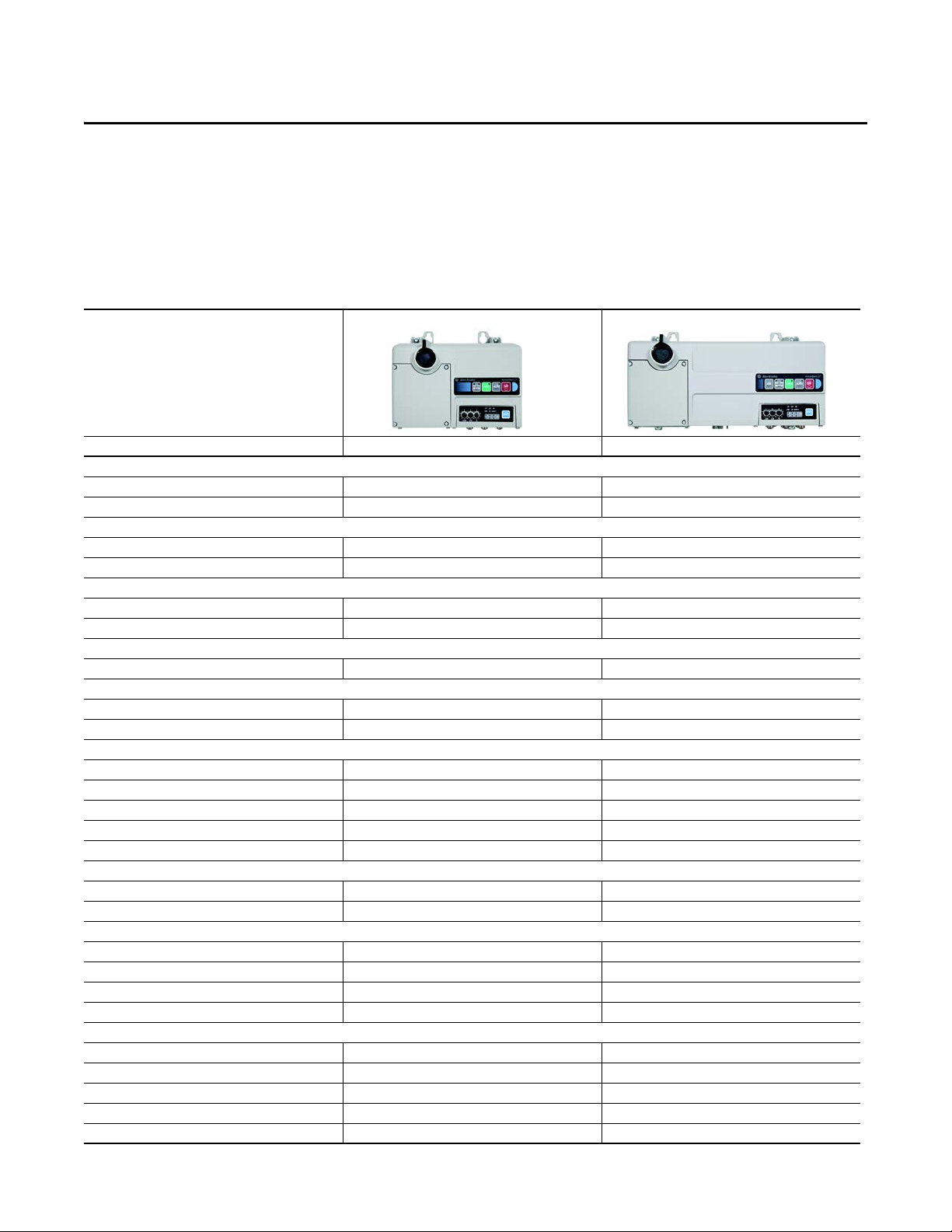
Product Overview
Bulletin 290/291 294
Network Communications:
EtherNet/IP
DeviceNet
Horsepower Range:
0.5…5 Hp (0.37…3.3 kW)
0.5…2 Hp (0.37…1.5 kW)
Starting Method:
Full-Voltage and Reversing
VFD (V/Hz) —
Environmental Rating:
IP66/UL Type 4/12
Control Voltage:
24V DC
Internal Power Supply (sourced from 3-phase)
Operational Voltage Ratings:
200…480V DC
380…480V DC —
Rated for Group Motor Installations
Local logic using DeviceLogic™
Peer-to -Peer (ZI P)
I/O Capability:
Six Self-Configurable Points
LED Status Indication
Gland Plate Entry:
Conduit Entrance
ArmorConnect® Power and Control Media (option)
Quick Disconnects: I/O and Communications
EMI Filter —
Factory Installed Options:
Manual-Auto-Off HOA Keypad
Source Brake Contactor —
Internal 24V DC Power Supply
Optional Motor Cables
ArmorConnect Gland
DeviceNet Version Only
—
—
—
DeviceNet Version Only
Rockwell Automation Publication 290D-UM001A-EN-P - June 2012 17
Page 18

Chapter 1 Product Overview
Description
ArmorStart LT is available with Full Voltage, Full Voltage Reversing, or Variable
Speed motor control performance. It comes equipped with a UL Listed At-motor
disconnect that supports a lock-out tag-out (LOTO) provision. ArmorStart LT
is listed as suitable for group installations per UL and can be applied with either
branch circuit breaker protection or fuse protection. It provides a robust IP66/
UL Type 4/12➊ enclosure suitable for water washdown environments in a single
box construction that will minimize inventory needs. All external connections
are made from the bottom of the unit minimizing accidental contact by moving
equipment. ArmorStart LT as a standard will come with quick disconnect
receptacles for the I/O and network connections. And finally, ArmorStart LT
will include DeviceLogix, a high-performing local logic engine when a fast I/O
response is critical to the application.
ArmorStart LT leverages the capabilities of the Rockwell Automation® Integrated
Architecture so you can achieve an unmatched level of integration and ease
of use. The architecture of ArmorStart LT allows Premiere Integration with
Allen-Bradley® ControlLogix® or CompactLogix™ line of Automation Controllers
and PLCs.
The ArmorStart LT is available with options that can further reduce installation
and commissioning time and cost
, such as:
• Quick disconnect receptacles for power, control, and motor connections
• Local Hand-Off-Auto keypad for manual control.
• Internal power supply (IPS) eliminating the need to run additional control
power to each unit
• Bulletin 294 can be ordered with an electromechanical brake connection
(source brake)
• EDS Tag Generator tool with RSLogix 5000
➊ The G2 gland option is rated IP66/ UL Type 4
18 Rockwell Automation Publication 290D-UM001A-EN-P - June 2012
Page 19

Product Overview Chapter 1
IMPORTANT
Features
The ArmorStart LT provides many features and benefits that are unsurpassed in
the market place:
• Robust IP66, UL Type 4/12 enclosure
• UL Listed, Suitable for Group Motor Applications
• UL Listed, At-motor disconnect switch
• Native support for DeviceNet
• 6 user configurable I/O points
• DeviceLogix
• Zone interlock protocol (ZIP)
• Optional internal power supply
• Optional electromechanical brake contactor
• Optional local control via Hand-Off-Auto keypad
• Optional quick disconnect for power and motor connections
Not all options are available for Bulletin 290D/291D/294D. Refer to the catalog
configurator for details.
Rockwell Automation Publication 290D-UM001A-EN-P - June 2012 19
Page 20

Chapter 1 Product Overview
Feature Description
Standard Features Across Product Family
UL Listed “Suitable for Group Motor Applications” — Where NFPA 70
(NEC) or 79 are required installation standards, this Listing allows two or more
motors to be connected to the same branch circuit without individual motor
branch short circuit or ground fault protection. Refer to Appendix A for details.
At-motor disconnect switch — ArmorStart LT offers a local ON/Off motor
disconnecting means with lockout-tagout provision. Industrial standards require
a local at-motor disconnect to be within eye sight of the motor for maintenance
or other shutdown reasons. Refer to your installation code for details.
User configurable I/O — ArmorStart LT offers 6 user configurable I/O points
to be used with sensors and actuators. By default all 6 points are configured as
sinking 24V DC inputs. The user has the option to select any point as a sourcing
24V DC output.
DeviceNet Network Capabilities
The ArmorStart Distributed Motor Controller delivers advanced capabilities to
access parameter settings and provides fault diagnostics, and remote start-stop
control.
DeviceLogix — ArmorStart LT offers local programmable logic via
DeviceLogix. DeviceLogix is a stand-alone program that resides within the
ArmorStart LT. It is programmed locally using the Add-On-Profile and
implements operations such as, AND, OR, NOT, Timers, Counters, Latches,
and Analog operations. DeviceLogix can run as a stand-alone application,
independent of the network or collaboratively with the PLC. However,
unswitched control power must be maintained for DeviceLogix to operate.
Zone Interlock Protocol (ZIP) — The zone control capabilities of ArmorStart
LT is ideal for motored conveyors. Zone Interlocking Parameters (ZIP) allow one
ArmorStart to receive data directly, from up to four other DeviceNet nodes,
without going through a network scanner. These direct communications
between conveyor zones are beneficial in a merge, diverter, or accumulation
conveyor application.
Quick disconnect for I/O and network — ArmorStart LT offers quick
disconnect connectors for I/O and communications.
DeviceNet node address — ArmorStart LT offers external accessible address
switches for device node address configuration. The address can be set statically
or dynamically.
EMI filter — ArmorStart LT for VFD application (Bulletin 294) provides an
internal EMI filter and is CE compliant. For CE compliant installations refer to
the recommended EMI/RFI cord grip accessory. For availability of the quick
20 Rockwell Automation Publication 290D-UM001A-EN-P - June 2012
Page 21

Product Overview Chapter 1
disconnect shielded motor cable contact your local sales representative for
details.
Local and remote status and diagnostics — ArmorStart LT offers
comprehensive status and diagnostics for I/O, Network, and device health via 12
LEDs found on the electronic control module (ECM). If a fault occurs a local
fault reset button allows the user to quickly get the process started after corrective
action is taken. The user can also configure the embedded web server to send an
e-mail when a fault or warning occurs.
Gland plate entrance — ArmorStart LT offers different methods of connecting
three-phase, control power, and motor. ArmorStart LT has conduit entrance
openings, as standard.
Factory-Installed Options
Internal power supply (IPS) — ArmorStart LT offers the user an optional
24V DC internal power supply. The internal power supply provides all control
and I/O power needs and is sourced from the incoming 3-phase power. This
eliminates the need to run separate control power to each unit, reducing
installation time and cost. The local at-motor disconnect will remove power
from the motor terminals and outputs when in the OFF condition.
Hand/Off/Auto (HOA) keypad — ArmorStart LT offers an optional local
Hand-Off-Auto keypad. This key pad allows local start/stop motor control
regardless of PLC status. This option can be used for troubleshooting or
maintenance operations. The HOA can also be disabled when local control
is not allowed, using parameter 67.
Source brake — ArmorStart LT provides an optional, internally-controlled
electromechanical motor brake contactor. The motor brake power is sourced
from 3-phase power, L1 and L2.
Quick disconnect gland — ArmorStart LT offers a plug -n- play solution that
simplifies wiring and installation. These factory installed quick disconnect
receptacles provide connectivity to ArmorConnect® media for three-phase,
control, and motor connections. The cables are ordered separately.
Rockwell Automation Publication 290D-UM001A-EN-P - June 2012 21
Page 22
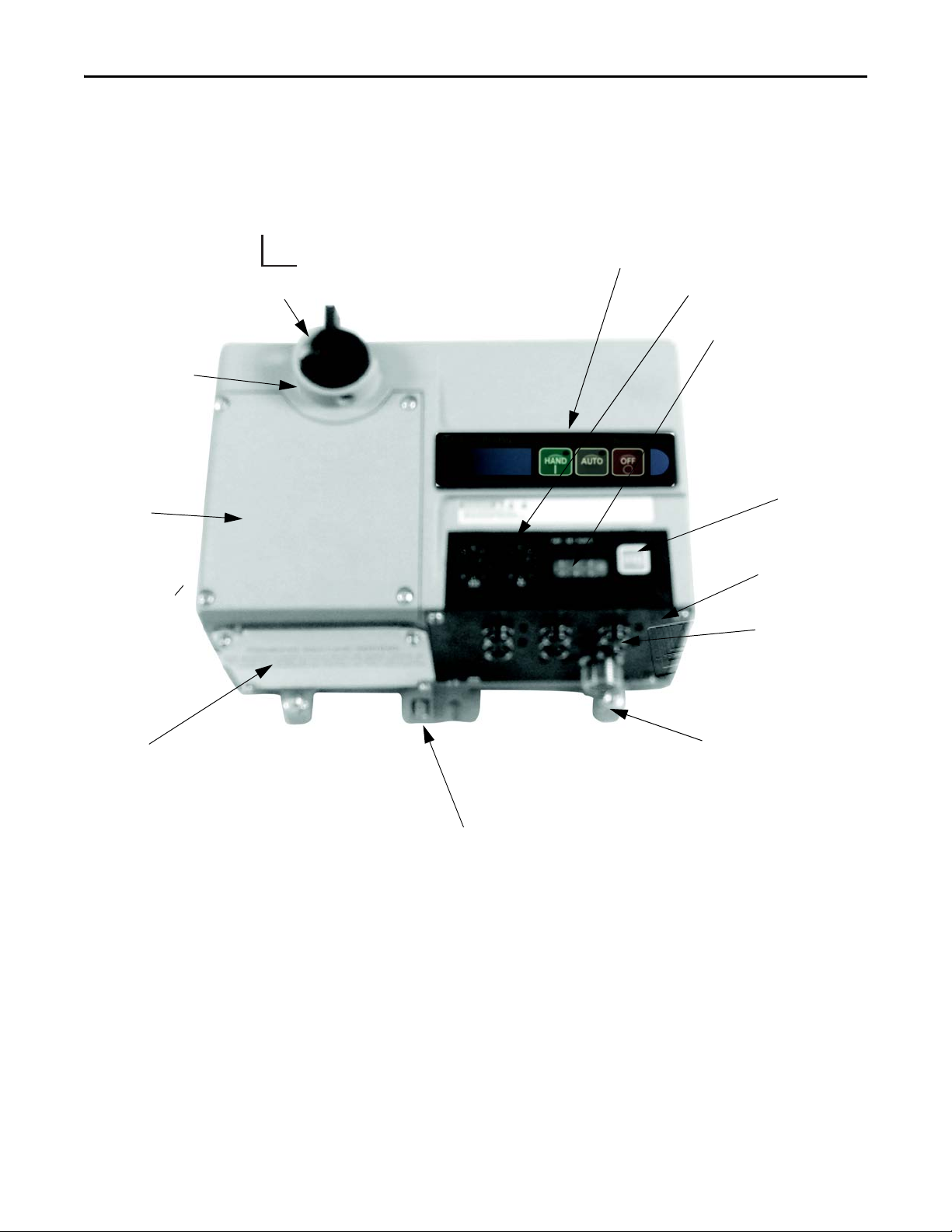
Chapter 1 Product Overview
6 Configurable I/Os
LockOut/TagOut Provision
Wiring Access
Reset
IP Address Switches
On/Off Switch
HOA Keypad (optional)
Gland Plate – Conduit/Cord Grip or
ArmorConnect
®
Media (optional)
Status and Diagnostic LEDs
DeviceNet Connector
ECM (Electronic
Control Module)
Protective Earth (PE)
ArmorStart LT Characteristics
0
O
1
On
Figure 1 - Bulletin 290D/291D ArmorStart LT
22 Rockwell Automation Publication 290D-UM001A-EN-P - June 2012
Page 23

Product Overview Chapter 1
➊ IP66/UL Type 4 is available with all gland option s. UL Type 4/12 is available with G1 an d G3 gland option.
➋ See selection guide 290-SG001_-EN-P Accessories section for gland configurations and ordering
➌ Leave blank unless there is a customer-specific opt ion defined by the factory.
Catalog Number Explanation
Examples given in this section are for reference purposes. This basic explanation
should not be used for product selection; not all combinations will produce a
valid catalog number.
290 E - F A Z - G1 - Option 1 - Option 2
—————— —— ——
abcde f g h
a
Bulletin Number
Code Description
290 Full-Voltage Starter
291 Reversing Starter
b
Communications
Code Description
E EtherNet/IP
D DeviceNet
Code D escrip tion
Z External 24V DC control power
PInternal power supply
Code D escrip tion
G1 Conduit entry
G2 ArmorConnect
G3 Gland Kit➋
e
Control Voltag e
f
Gland Plate Options
(Power and Motor)
c
Enclosure Type
Code Description
F UL Type 4/12 ➊
d
Overload Selection
Code Description
A 0.25…3.5 A
B 1.1…7.6 A
g
Option 1
Code D escrip tion
3 Hand/Off/Auto selector keypad
3FR Hand/Off/Auto selector keypad with
Code Desc ription
blank
➌
Forw ard/Reve rse
h
Option 2
No option
Rockwell Automation Publication 290D-UM001A-EN-P - June 2012 23
Page 24
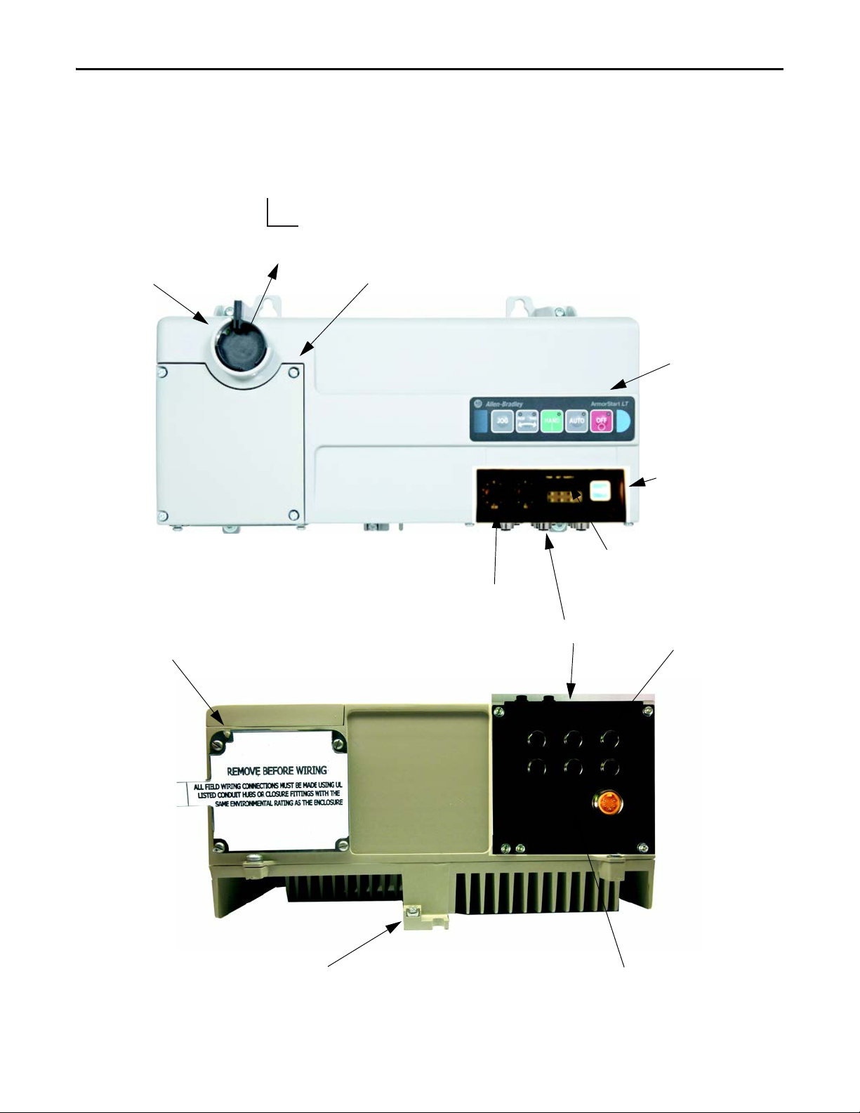
Chapter 1 Product Overview
Bottom View
1
On
0
O
Protective Earth (PE)
DeviceNet connector
LockOut/TagOut Provision
Gland Plate – Conduit/Cord Grip or
ArmorConnect Media (optional)
Reset
IP Address Switches
ECM (Electronic Control Module)
Hand-Off-Auto Keypad
(optional)
On/Off Switch
Status and Diagnostic LEDs
Wiri ng Acces s
6 Configurable I/Os
ArmorStart LT Characteristics
Figure 2 - Bulletin 294D ArmorStart LT
24 Rockwell Automation Publication 290D-UM001A-EN-P - June 2012
Page 25

Product Overview Chapter 1
➊ IP66/UL Type 4 is available with all gland options. UL Type 4/12 is available with G1 and G3 gland option.
➋ Leave blank unless there is a customer-specific option defined by the factory.
Catalog Number Explanation
Examples given in this section are for reference purposes. This basic explanation
should not be used for product selection; not all combinations will produce a
valid catalog number.
294 E - F D1P5 Z - G1 - Option 1 - Option 2
——————————
abc d ef g h
a
Bulletin Number
Code Description
294 VFD Starter
b
Communications
Code Description
E EtherNet/IP
D DeviceNet
Code D escrip tion
Z External 24V DC control power
PInternal power supply
Code D escrip tion
G1 Conduit entry
G2 ArmorConnect
G3 Gland Kits ➋
e
Control Voltag e
f
Gland Plate Options
(Power and Motor)
c
Enclosure Type
Code Description
F UL Type 4/12 ➊
d
Output Current
Code Description
D1P5 1.5 A (0.4 kW), 0.5 Hp
D2P5 2.5 A (0.75 kW), 1.0Hp
D4P2 3.6 A (1.5 kW), 2.0Hp
g
Option 1
Code D escrip tion
3 Hand/Off/Auto selector keypad with Jog
Code Desc ription
SB S ource Brake
blank
➌
function
h
Option 2
No option
Rockwell Automation Publication 290D-UM001A-EN-P - June 2012 25
Page 26
Chapter 1 Product Overview
Outputs
Inputs
EtherNet
Comms
A3
A1
A2
O
Switched Control Power
Unswitched Control Power
Motor
Control
Motor
Controller
Class 2
External
24VDC Power
Supply
Disconnect
24VDC
+
-
L1 L2
L3
T1 T2
T3
* Control power output is determined by disconnect status
*
ArmorStart LT
L
N
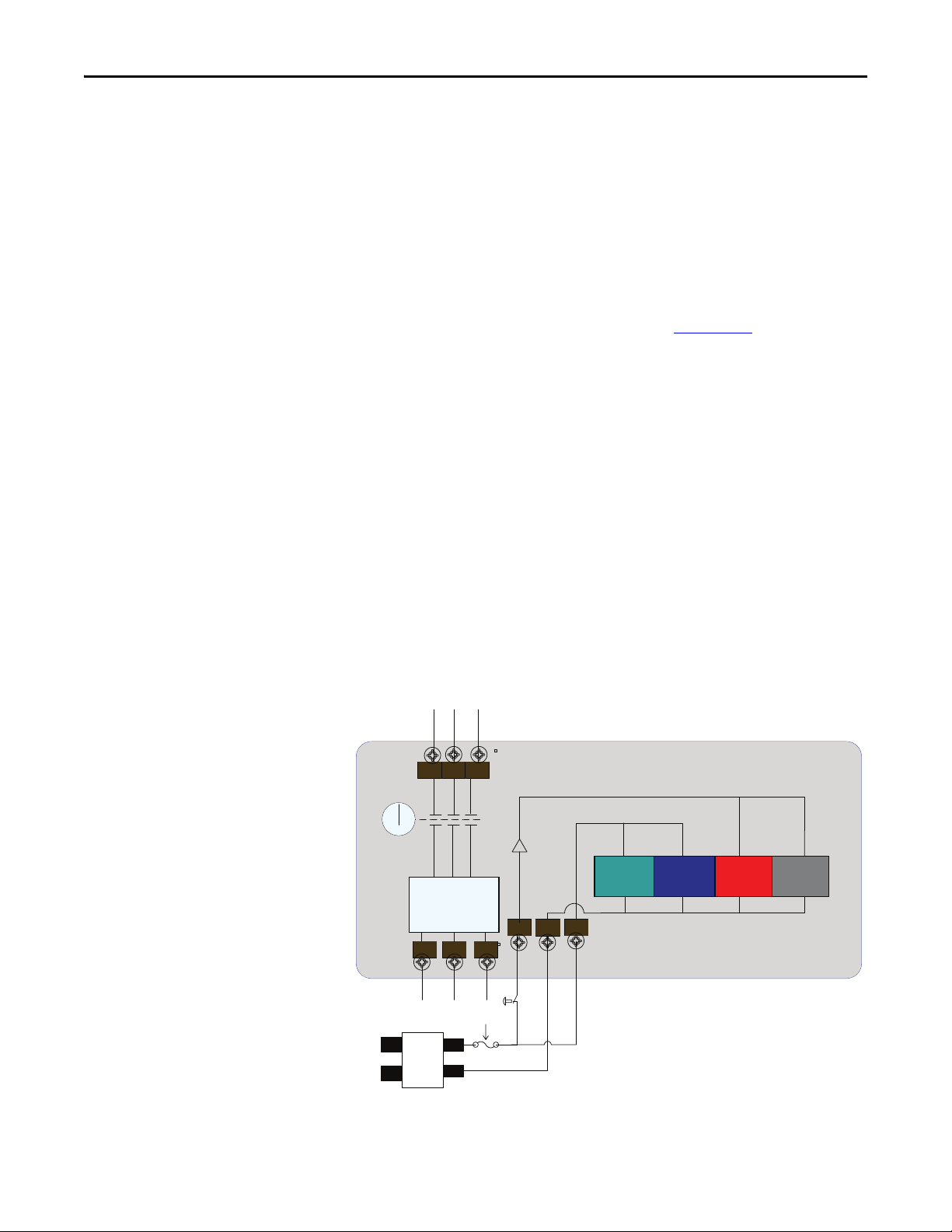
Basic Operation
Group Motor Installations for USA and Canada Markets
The ArmorStart LT Distributed Motor controllers are listed for use with each
other in group installations per NFPA 79, Electrical Standard for Industrial
Machinery and NFPA 70, the National Electrical Code. When applied according
to the group motor installation requirements, two or more motors are permitted
on a single branch circuit. Group Motor Installation has been successfully used
for many years in the USA and Canada.
Note: For additional information regarding group motor installations with the
ArmorStart LT Distributed Motor Controller, see Appendix A
.
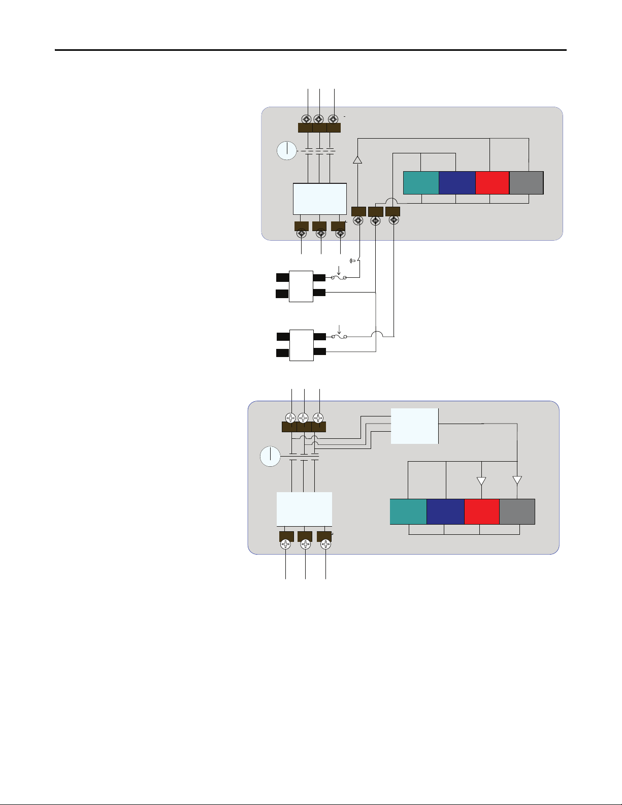
Control Circuit
ArmorStart LT accepts a 24V DC Class 2 input power supply for switched
and unswitched power. The control voltage provides power to the inputs
(unswitched) and outputs (switched). Unswitched control voltage is used to
ensure no loss of network connectivity, sensor, or other field input status under
normal operation. The control power terminal connections are labeled A1, A2,
and A3. Switched power is identified as (+A1) (-A2). Unswitched power is
identified as (+A3) (-A2).
As an option, ArmorStart LT can be supplied with an internal power supply
(IPS) eliminating the need for an external control power. The IPS is sourced from
the line side of 3-phase power and is not impacted by the status of the local atmotor disconnect switch.
Figure 3 - Control Circuit Wiring Diagram — Single External Power Supply
26 Rockwell Automation Publication 290D-UM001A-EN-P - June 2012
Page 27
Product Overview Chapter 1
Outputs
Inputs
EtherNet
Comms
A3
A1
A2
O
Switched Control Power
Unswitched Control Power
Motor
Control
Motor
Controller
Class 2
External Switched
24VDC Power Supply
Disconnect
24VDC
+
-
L
N
L1 L2
L3
24VDC
+
-
L
N
Class 2
External Unswitched
24VDC Power Supply
* Control power output is determined by disconnect status
*
T1 T2
T3
ArmorStart LT
Outputs
Inputs
EtherNet
Comms
O
Motor
Control
Motor
Controller
Disconnect
Internal Power
Supply
*
* Control power output is determined by disconnect status
T1 T2
T3
ArmorStart LT
*
L2L3L1
Figure 4 - Control Circuit Wiring Diagram — Multiple External Power Supplies
Figure 5 - Control Circuit Wiring Diagram — Internal Power Supply (optional)
Rockwell Automation Publication 290D-UM001A-EN-P - June 2012 27
Page 28

Chapter 1 Product Overview
Motor Circuit
The ArmorStart LT Distributed Motor Controllers are rated to operate the
following types of three-phase squirrel-cage induction motors:
Bulletin 290D/291D:
0.5 Hp (0.37 kW) to 5 Hp (3 kW) @ 480/277V AC
Bulletin 294D:
0.5 Hp (0.37 kW) to 2 Hp (1.5 kW) @ 480/277V AC
Local I/O
The ArmorStart LT provides as standard, 6 user configurable I/O points. By
default, all points are configured as an Input. The user will need to refer to
parameter 49 [IOPointConfiguration], to define an output point.
Overload Protection
Mode of Operation Bulletin 290D/291D
The ArmorStart LT Distributed Motor Controller incorporates, as standard,
electronic motor overload protection. This overload protection is accomplished
2
electronically with an I
programmable via the communication network, providing the user with greater
flexibility.
The Bulletin 290D/291D includes programmable overload Class 10, 15, and 20
protection. The Bulletin 294D provides overload protection: 150% for 60 s and
200% for 3 s.
Refer to Chapter 6
t algorithm. The ArmorStart LTs overload protection is
, Specifications, for additional information.
Full-Voltage Start
This method is used in applications requiring across-the-line starting, in which
full inrush current and locked-rotor torque are realized. The ArmorStart LT
Bulletin 290D offers full-voltage starting and Bulletin 291D offers full-voltage
starting for reversing applications, from 0.5 Hp (0.37 kW) to 5 Hp (3 kW) at
480Y/277V AC, 3-phase power.
28 Rockwell Automation Publication 290D-UM001A-EN-P - June 2012
Page 29
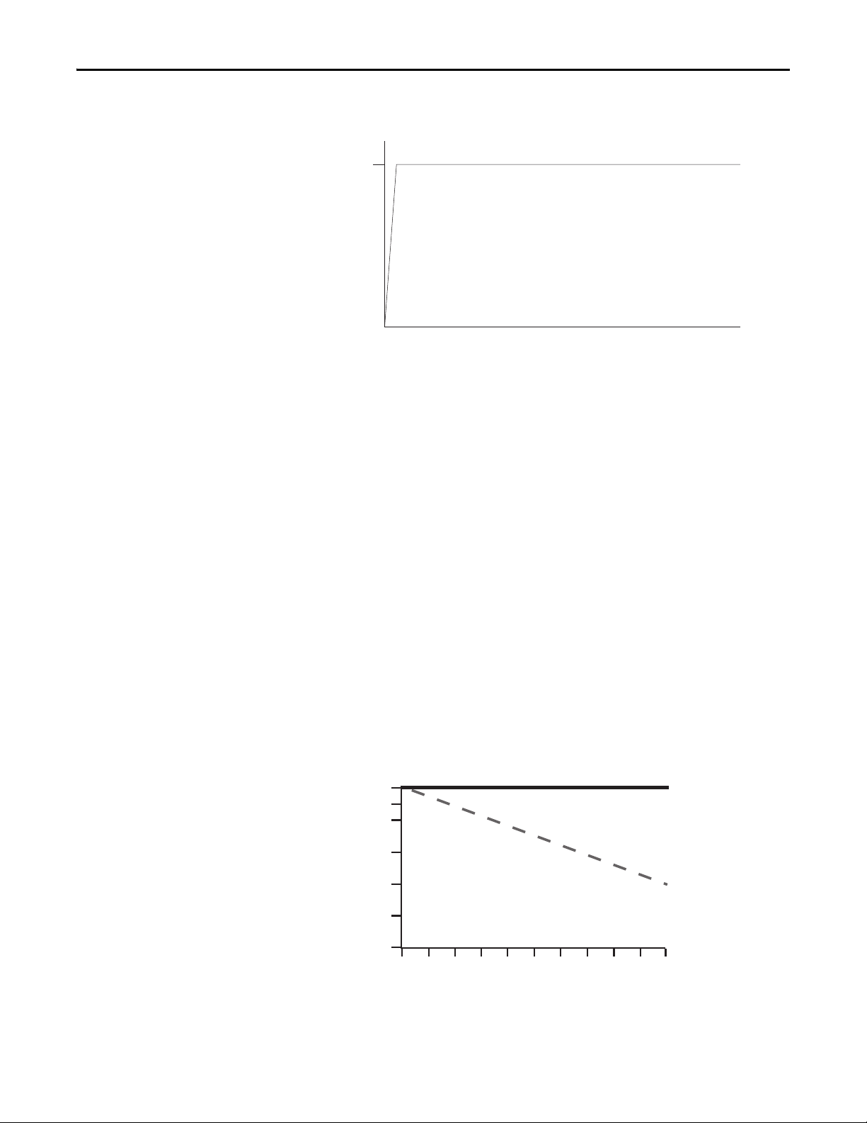
Figure 6 - Full-Voltage Start
100%
Percent Voltage
Time (seconds)
% of speed
% of load
With Slip
Compensation
Without Slip
Compensation
100
99
98
97
96
95
0 102030405060708090100
Product Overview Chapter 1
Mode of Operation Bulletin 294D
Sensorless Vector Performance
Using a distributed AC drive to operate mechanical equipment at optimum
speed helps reduce energy costs and eliminates mechanical wear and tear that can
occur in the mechanical parts. The advance monitoring found in ArmorStart LT
protects critical equipment against unplanned downtime with advanced
diagnostics and notification of irregular operating parameters. ArmorStart LT
provides open-loop speed regulation (V/Hz) with slip compensation. This
provides excellent speed regulation and high levels of torque across the entire
speed range of the drive, and improved speed regulation as loading increases.
Open Loop Speed Regulation with Slip Compensation allows the VFD to
automatically adjust the output frequency to compensate for speed changes due
to motor loading. This feature utilizes an open loop, current feedback, slip
compensation circuit. Slip Compensation works as an open loop speed regulator
that increases the output frequency of the drive as the load is increased, or
decreases the frequency as the load drops. This feature is used where the motor
must run at a relatively constant speed regardless of torque output.
Rockwell Automation Publication 290D-UM001A-EN-P - June 2012 29
Page 30

Chapter 1 Product Overview
Status LEDs and Reset
Indicator Description Color_1 Color_2
PWR LED The bicolor (green/yellow) LED shows the
RUN/FLT LED The bicolor (green/red) LED combines the
NET – Network Status
LED
I/O Status
Enunciators 0…5
LEDs
Reset Button The blue reset button will cause a
Figure 7 - Status, Diagnostic LEDs, and Reset
ArmorStart LT provides comprehensive status and diagnostics via 12 individually
marked LEDs shown in Figure 7
local reset is provide for clearing of faults. Ta b l e 4
status LEDs.
Table 4 - ArmorStart LT Status and Diagnostics Indicators
state of the control voltage. When LED is
off, switched and/or unswitched power is
not present.
functions of the Run and Fault LEDs.
The bicolor (green/red) LED indicates the
status of the CIP network connection. See
Network Status Indicator for further
information.
Flashing bicolor (red/green) indicates a
self-test on power up.
Six yellow LEDs are numbered 0…5 and
indicate the status of the input/output
connectors. One LED for each I/O point.
protection fault reset to occur.
, located on the ECM module. In addition, a
Solid green is illuminated when switched
and unswitched control power is within its
specified limits and has the proper polarity.
Solid green is illuminated when a Run
command is present.
Flashing green indicates an IP address is
configured, no CIP connections are
established, and an Exclusive Owner
connection has not timed out.
Steady green indicates at least one CIP
connection is established and an Exclusive
Owner connection has not timed out.
Yellow is illuminated when input is valid or
output is on.
——
details the diagnostic and
Solid yellow is illuminated when switched
or unswitched control power is outside its
specified limits or has incorrect polarity.
The LED will blink red in a prescribed fault
pattern when a protection fault (trip)
condition is present. See Tab le 5 for fault
blink patterns.
Flashing red indicates the connection has
timed out. Steady Red indicates a duplicate
IP Address detected.
Off when input is not valid or the output is
not turned on.
Electronic Data Sheet (EDS)
ArmorStart LT EtherNet/IP has an embedded electronic data sheet. An EDS
consists of specially formatted text files, as defined by the CIP™. EDS files contain
details about the readable and configurable parameters of the device. They also
provide information about the I/O connections that the device supports and the
content of the associated data structures. EDS are used by device configuration
tools, such as RSNetWorx™, and data servers such as RSLinx® Classic.
EDS files for all ArmorStart LT devices can be uploaded directly from the device
via the web server interface. Rockwell Automation product EDS files are also
available on the internet at: http://www.ab.com/networks/eds
30 Rockwell Automation Publication 290D-UM001A-EN-P - June 2012
.
Page 31

Product Overview Chapter 1
Fault Diagnostics
Fault diagnostics capabilities built in the ArmorStart LT Distributed Motor
Controller are designed to help you pinpoint a problem for easy troubleshooting
and quick re-starting.
Protection Faults
Protection faults will be generated when potentially dangerous or damaging
conditions are detected. Protection faults are also known as “trips” or “faults”.
These faults will be reported in multiple formats, including:
• Bit enumeration in the TripStatus parameter 16 in DeviceLogix
• In the ArmorStart LT web server for ArmorStart EtherNet/IP version
• As a sequence of LED flashes on the ECM
Table 5 - Protection Faults
LED Flash Bit Enumeration 290D/291D Trip Status Bits 294D Trip Status Bits
10OverloadTrip ➊ OverloadTrip ➊
2 1 PhaseLossTrip PhaseLShortTrip
32UnderPowerTrip ➊ UnderPowerTrip ➊
4 3 SensorShor tTrip ➊ SensorShortTrip ➊
5 4 PhaseImbalTrip OverCurrentTrip
65NonVolMemoryTrip ➊ NonVolMemoryTrip ➊
76reserved ParamSyncTrip ➊
8 7 JamTrip DCBusOrDiscnnct ➊
98StallTrip StallTrip ➊
10 9 U nderloadTr ip OverTemperature ➊
11 10 reserved GroundFault ➊
12 11 reserved RestartRetries
13 12 reserved DriveHdwFault ➊
14 13 OutputShortTrip ➊ OutputShortTrip ➊
15 14 UserDefinedTrip UserDefinedTrip
16 15 HardwareFltTrip ➊ Hardwa reFltTrip ➊
➊ Cannot be disabled.
Rockwell Automation Publication 290D-UM001A-EN-P - June 2012 31
Page 32

Chapter 1 Product Overview
Protection Warnings
ArmorStart LT supports fault warnings. Refer to the WarningStatus parameter
(param 17).
The following describes the warning conditions for 290D/291D units:
Bit Number
14
15 ConfigWarning
Bit Enumeration Description
0 OverloadWarning This warning is generated when the value of %ThermalUtilized (param n5)
2UnderPowerWarn
4 PhaseImbalWarn This warning is generated in firmware by monitoring the relative levels of the
7 JamWarning This warning is generated in firmware when RMS current is greater than the
9 UnderloadWarning This warning is generated in firmware when RMS current is less than the
UnswitchedPwrWarn
becomes greater than the value of the OLWarningLevel parameter (param 69).
This warning is generated when switched power dips below 19.2 V for more than 4 ms.
three phase currents. When the % imbalance becomes greater than the hard
coded warning limit, the warning is generated.
JAMWarningLevel (param 73) after the JamInhibitTime (param 70) has expired.
ULWarningLevel (param 79) after the ULInhibitTime (param 76) has expired.
This warning is generated when unswitched power dips below 19.2 V for 4 ms.
This warning is generated when parameter configuration values that are inconsistent
with certain device options are written. This warning may not be disabled.
The following describes the warning conditions for 294D units:
Bit Number
12 FanWarning This warning indicates that either the fan is running between 62% and 70% of
14
15 ConfigWarning
Bit Enumeration Description
2UnderPowerWarn
6 DriveParamInit This warning is generated when a Full Control Module to Drive parameter sync is in
UnswitchedPwrWarn
This warning is generated when switched power dips below 19.2 V for more than 4 ms.
progress, either on power up, or after an internal comms loss has been remedied.
rated RPM or that the “kick start” was needed to turn on the fan.
This warning is generated when unswitched power dips below 19.2 V for 4 ms.
This warning is generated when parameter configuration values that are inconsistent
with certain device options are written. This warning may not be disabled.
32 Rockwell Automation Publication 290D-UM001A-EN-P - June 2012
Page 33

Product Overview Chapter 1
Table 6 - Configuration Warnings
The following conditions will result in a configuration warning being generated:
Warning Type Warning Code Description
BrakeConfig 41 If Param 89 (BrakeMode) is set to anything other than
IOPointConfig 42 If Param 58 (Input00Function) thru Param 63 (Input05Function)
ZIPConfig 43 If Param 114 (Zone1PtMask) thru Param 121 (Zone4PtOffset)
JamConfig 44 If Param 72 (JamTripLevel) is less than Param 73
UnderLoadConfig 45 If Param 78 (ULTripLevel) is greater than Param 79
0=NoBrakeControl when brake hardware not present OR
If Param 89 (BrakeMode) is set to 1=AboveFrequency and
Param 90 (BrakeFreqThresh) is set to a value above Param
35 (MaximumFreq) OR
If Param 89 (BrakeMode) is set to 2=AboveCurrent and Param
91 (BrakeCurrThresh) is set to a value above Param 31
(Curren tLimit)
are set to 5=BrakeRelease and no brake is present OR
If Param 58 (Input00Function) thru Param 63 (Input05Function)
are set t0 anything other than 0=NoFunction while the
corresponding bit in Param 49 (IOPointConfigure) is set to
configure it as an output.
are set to have a mapping overlap, and Param 143
(ZoneCtrlEnable) set to Enabled OR
If Param 122 (Zone1AnalogMask) thru Param 129
(Zone4AnOffset) are set to have a mapping overlap, and Param
143 (ZoneCtrlEnable) set to Enabled
(JamWarningLevel)
(ULWarningLevel)
Rockwell Automation Publication 290D-UM001A-EN-P - June 2012 33
Page 34

Chapter 1 Product Overview
Optional HOA Selector Keypad
Keypad Local Control
The HOA Selector Keypad allows for local start/stop/jog control in forward/
reverse motor direction. If two buttons are pressed simultaneously, this action is
ignored by the device unless one of the buttons is the Off button. If the Off
button is pressed at any time, the unit will go to the off state. When local Hand
mode is entered, speed reference is switched to Internal Frequency. When in
“Auto” mode the unit the speed reference is switched to the mode specified in
parameter 33 “SpeedReference”.
HAND The Hand key will initiate starter operation
AUTO
OFF
DIR Arrow
JOG
The Auto key allows for Start/Stop control via the
communications network
If the starter is running, pressing the OFF key will cause the
starter to stop.
The Dir arrow selects the direction of the motor, either forward
or reverse.
When pressed, JOG will be initiated if no other control devices
are sending a stop command. Releasing the key will cause the
drive to stop, using selected stop mode.
Optional HOA Keypad Configuration (Bulletin 290D/291D only)
The ArmorStart LT offers optional factory-installed Hand/Off/Auto (HOA)
configurations: Standard (Bulletin 290D) and Forward/Reverse (Bulletin
291D).
Figure 8 - Bulletin 290D Standard HOA
Figure 9 - Bulletin 291D Forward/Reverse HOA
E
34 Rockwell Automation Publication 290D-UM001A-EN-P - June 2012
Page 35

Product Overview Chapter 1
Bulletin 290D
With the KeypadMode parameter (parameter 66) set to 1 = Maintained, pressing
the buttons reacts like a maintained switch.
Current Mode
Key Press
AUTO Auto Mode — Motor Off — —
HAND If no fault, Motor On — —
OFF — Motor turns Off Motor turns Off
FAULT PRESENT — Motor turns Off Motor turns Off
With the KeypadMode parameter (parameter 66) set to 0 = Momentary,
pressing the buttons reacts like a momentary switch.
Key Press
NO KEY PRESSED — Motor Off —
AUTO Auto Mode — Motor Off — —
HAND If no fault, Motor On — —
OFF — Motor Off Motor Off
PROTECTION FAULT PRESENT — Motor Off —
OFF HAND AUTO
Current Mode
OFF Key HAND AUTO Key
Bulletin 291D
With the KeypadMode parameter (parameter 66) set to 1 = Maintained, pressing
the buttons reacts like a maintained switch.
Current Mode
Key Press
FWD/REV FWD LED Set REV LED
AUTO Auto Mode — Motor Off — —
HAND If no fault, Motor On — —
OFF Ignore Motor Off Motor Off
PROTECTION FAULT PRESENT Ignore Motor Off —
With the KeypadMode parameter (parameter 66) set to 0 = Momentary,
pressing the buttons reacts like a momentary switch.
Key Press
NO KEY PRESSED — Motor Off —
FWD/REV FWD LED Set REV LED
AUTO Auto Mode — Motor Off — —
HAND If no fault, Motor On — —
OFF — Motor Off Motor Off
PROTECTION FAULT PRESENT — Motor Off —
OFF HAND AUTO
REV LED Set FWD LED
OFF HAND AUTO
REV LED Set FWD LED
——
Current Mode
——
Rockwell Automation Publication 290D-UM001A-EN-P - June 2012 35
Page 36

Chapter 1 Product Overview
IMPORTANT
Optional HOA Selector Keypad with Jog Function (Bulletin 294D only)
The HOA Selector Keypad with Jog function allows for local start/stop control
with capabilities to jog in forward/reverse motor directions.
Figure 10 - Bulletin 294D Jog/Forward/Reverse HOA
Keypad Local Control
With the KeypadMode parameter (parameter 66) set to 1 = Maintained, pressing
the buttons reacts like a maintained switch.
Current Mode
Key Press
NO KEY PRESSED — — Motor Off —
FWD/REV FWD LED Set REV LED
JOG If no fault, Jog Motor — — —
AUTO Auto Mode — Motor O ff — — —
HAND If no fault, Motor On — — —
OFF — Motor Off Motor Off Motor Off
PROTECTION FAULT PRESENT — Motor Off Motor Off —
OFF HAND JOG AUTO
REV LED Set FWD LED
FWD LED Set REV LED
REV LED Set FWD LED
——
With the KeypadMode parameter (parameter 66) set to 0 = Momentary,
pressing the buttons reacts like a momentary switch.
Current Mode
Key Press
NO KEY PRESSED — Motor Off Motor Off —
FWD/REV FWD LED Set REV LED
JOG If no fault, Jog Motor — — —
AUTO Auto Mode — Motor O ff — — —
HAND If no fault, Motor On — — —
OFF — Motor Off Motor Off Motor Off
PROTECTION FAULT PRESENT — Motor Off Motor Off —
OFF HAND JOG AUTO
REV LED Set FWD LED
FWD LED Set REV LED
REV LED Set FWD LED
——
If multiple buttons are pressed at the same time, the software interprets this as
a “no button pressed” condition. The only exception to this rule is if multiple
buttons are pressed and one of them is the Off button. If the Off button is
pressed in combination with any combination of other buttons, the processor
will behave as if the Off button were pressed by itself.
36 Rockwell Automation Publication 290D-UM001A-EN-P - June 2012
Page 37

Product Overview Chapter 1
Keypad Disable Parameter
“Keypad Disable”, parameter 67, only inhibits the “HAND”, “FWD”, “REV” and
“JOG” buttons on the HOA keypad. The “OFF” and “AUTO” buttons are
always enabled, even if parameter 67 is set to “1=Disable”. The keypad OFF
button can not be disabled.
Source Brake Contactor and Connector (Bulletin 294D only)
An internal contactor is used to switch the electromechanical motor brake
On/Off. The motor brake contactor is actuated via the internal power which
supplies L1 and L2 voltage to the mechanical brake in the motor. The source
brake can be configured for independent control via parameter configuration.
The internal contactor, electromechanical motor brake, and associated motor
branch cable are protected by the branch circuit protective device. There is no
resettable or replaceable protective device in ArmorStart LT.
WARNING: If the branch circuit protective device trips, the user must ensure
that the Source Brake function is still operational prior to putting the
equipment back in service. If the source brake function is not working properly,
loss of brake function or motor damage can occur.
Rockwell Automation Publication 290D-UM001A-EN-P - June 2012 37
Page 38

Chapter 1 Product Overview
Notes:
38 Rockwell Automation Publication 290D-UM001A-EN-P - June 2012
Page 39

Installation and Wiring
IMPORTANT
Chapter 2
Receiving
Unpacking
It is the responsibility of the user to thoroughly inspect the equipment before
accepting the shipment from the freight company. Check the item(s) received
against the purchase order. If any items are damaged, it is the responsibility of the
user not to accept delivery until the freight agent has noted the damage on the
freight bill. Should any concealed damage be found during unpacking, it is also
the responsibility of the user to notify the freight agent. The shipping container
must be left intact and the freight agent should be requested to make a visual
inspection of the equipment.
Remove all packing material, wedges, or braces from within and around the
ArmorStart LT distributed motor controller and other device(s). Check the
contents of the package to see if all contents are included. Contact your local
Allen-Bradley representative if any items are missing.
Before the installation and start-up of the drive, a general inspection
of mechanical integrity (i.e. loose parts, wires, connections, packing
materials, etc.) must be made.
Inspecting
Storing
After unpacking, check nameplate catalog number(s) of the item(s) against the
purchase order. See Chapter 1
which will aid in nameplate interpretation.
The controller should remain in the shipping container prior to installation.
If the equipment is not to be used for a period of time, it must be stored according
to the following instructions in order to maintain warranty coverage.
• Store in a clean, dry location.
• Store within an ambient temperature range of –25…+85 °C
(–13…+185 °F).
• Store within a relative humidity range of 0…95%, noncondensing.
• Do not store equipment where it could be exposed to a corrosive
atmosphere.
• Do not store equipment in a construction area.
Rockwell Automation Publication 290D-UM001A-EN-P - June 2012 39
for an explanation of the catalog numbering system
Page 40

Chapter 2 Installation and Wiring
Installation Precautions
Precautions for Bulletin 290D/291D Applications
The following statements must be read and understood.
ATTENTION: The earth ground terminal shall be connected to a solid earth
ground via a low-impedance connection.
ATTENTION: Copper ground conductors are recommended. The ArmorStart LT
external protective earth (PE) pad is aluminum. Refer to your local electrical
installation standard for proper bonding and protection when dissimilar metals
are used.
ATTENTION: An incorrectly applied or installed controller can damage
components or reduce product life. Wiring or application errors, such as
undersizing the motor, incorrect or inadequate AC supply, or out of range
ambient temperatures, may result in malfunction of the system.
SHOCK HAZARD: To prevent electrical shock, open appropriate machine
disconnect switch prior to connecting and disconnecting cables. Risk of shock —
environment rating may not be maintained with open receptacles.
Precautions for Bulletin 294D Applications
Dimensions
SHOCK HAZARD: The drive contains high voltage capacitors which take time
to discharge after removal of mains supply. Before working on drive, ensure
isolation of mains supply from line inputs (L1, L2, L3). Wait three minutes
for capacitors to discharge to safe voltage levels. Failure to do so may result
in personal injury or death.
ArmorStart LT consists of three components that are non-replaceable. The
Electronic Control Module (ECM); a gland plate for wire entry; and the
aluminum alloy enclosure which makes up the back cover, top housing, and
wiring access door. The ECM includes communications, discrete I/O, status and
diagnostic LEDs, and the node address switches. All mating surfaces are sealed
using foam in place gasket or o-ring.
40 Rockwell Automation Publication 290D-UM001A-EN-P - June 2012
Page 41

Installation and Wiring Chapter 2
Front View
Right Side View
Conduit Gland Entrance
ArmorConnect Internal Power
Supply Gland Plate (optional)
ArmorConnect Media
Gland Entrance (optional)
ArmorConnect Source Brake
Gland Plate (optional)
Line
Control
Motor
Line
Motor
Control
Line
Motor
Source Brake
260
[10.2]
170
[6.7]
217,83
[8.6]
130
[5.1]
65
[2.6]
202,05
[8.0]
38,49
[1.5]
57,13
[2.3]
37
[1.5]
24,25
[1.0]
48,5
[1.9]
0.75" CONDUIT OPENING
1" CONDUIT OPENING
IMPORTANT
For proper heat dissipation and product operation, mount the ArmorStart LT in the
vertical orientation as shown.
Dimensions
Dimensions are shown in millimeters (inches). Dimensions are not intended
to be used for manufacturing purposes. All dimensions are subject to change.
Figure 11 - Dimensions for Bulletin 290D/291D
Rockwell Automation Publication 290D-UM001A-EN-P - June 2012 41
Page 42

Chapter 2 Installation and Wiring
IMPORTANT
For proper heat dissipation and product operation, mount the ArmorStart LT in the
vertical orientation as shown.
Figure 12 - Dimensions for Bulletin 294D
381
[15.0]
240
[9.4]
219,32
206,43
[8.1]
120
[4.7]
Front View
37
[1.5]
[8.6]
170
[6.7]
92,9
[3.7]
38,49
[1.5]
24,25
Line
Motor
[1.0]
48,5
[1.9]
0.75" CONDUIT OPENING
Conduit Gland Entrance - Bottom View
ArmorConnect Internal Power
Supply Gland Plate (optional)
1" CONDUIT OPENING
Line
ArmorConnect Media Gland
Entrance (optional)
Control
Motor
Right Side View
Line
Motor
ArmorConnect Gland Entrance
with Source Brake (optional)
Control
Source Brake
42 Rockwell Automation Publication 290D-UM001A-EN-P - June 2012
Page 43

Dimensions are shown in millimeters (inches). Dimensions are not intended
to be used for manufacturing purposes. All dimensions are subject to change.
Figure 13 - ArmorStart LT Gland Plate Matrix
No Internal Power Supply
No Source Brake
Source Brake
No Internal Power Supply
Internal Power Supply
No Source Brake
Internal Power Supply
and Source Brake
1.00 in.
(25.4 mm)
0.75 in.
(19.05 mm)
0.75 in.
(19.05 mm)
1.00 in.
(25.4 mm)
0.75 in.
(19.05 mm)
1.00 in.
(25.4 mm)
0.75 in.
(19.05 mm)
G1 Conduit G2 Media
Standard
U.S. Trade Knock-outs
Dia. 25.5 mm
Dia. 20.5 mm
Dia. 25.5 mm
Dia. 20.5 mm
Dia. 25.5 mm
Dia. 20.5 mm
Dia. 25.5 mm
Dia. 20.5 mm
Installation and Wiring Chapter 2
G3 Conduit
Daisy Chaining
IP66 Metric Fittings
45°
Cat. No.
290-G3-A2
290-G3-A3
290-G3-A4
290-G3-A5
Connection Locations
User Modied
Gland Plate Clearances
Modications are not permitted in the keepout region. Fitting(s) should be oriented
so that they do not interfere with the enclosure when the gland plate is installed.
Torque the gland mounting screws to 12…14 in•lb (1.3…1.6 N•m).
Figure 14 - Internal Power, Control, and Ground Locations
66.1 mm
10.1 mm
91.3 mm
290-G3-A1
80.7 mm
11.8 mm
Rockwell Automation Publication 290D-UM001A-EN-P - June 2012 43
Page 44

Chapter 2 Installation and Wiring
Conduit Entry (Standard)
External PE
connection
Inputs/Outputs
Network
Optional ArmorConnect Quick
Disconnect Feature
Three-Phase
Power
Receptacle
Motor
Receptacle
Control Power
Receptacle
Figure 15 - Gland Connection
Gland Plate
Wiring Terminal Detail
The power, control, and ground wire capacity and the tightening torque
requirements are shown in Ta b l e 8
per terminal are shown in Ta b l e 7
. The maximum number of connections
. As shown in Figure 16 all the terminals are
found in the wiring area. Access can be gained by removing the terminal access
cover plate.
44 Rockwell Automation Publication 290D-UM001A-EN-P - June 2012
Page 45

Installation and Wiring Chapter 2
L2
L1
T1
L3
T2
T3
A2
A3
A1
PE
B1 B2
Wire Strip Length
0.35 ± 0.01 in.
(9 ± 0.2 mm)
Figure 16 - ArmorStart LT Power and Control Terminals
Table 7 - Power, Control, and Ground Terminal Designations
Terminal Designations Wires/Connections Description
A1 2 Switched 24V DC Control Power (+) ➊
A2 2 Control Power Common (–) ➊
A3 2 Unswitched 24V DC Control Power (+) ➊
PE 2 Ground
L1 2 Line Power – Phase A
L2 2 Line Power – Phase B
L3 2 Line Power – Phase C
T1 1 Motor Connection – Phase A
T2 1 Motor Connection – Phase B
T3 1 Motor Connection – Phase C
B1 1 Source Brake Connection – B1 ➋
B2 1 Source Brake Connection – B2 ➋
➊ When internal power supply option is selected, no connection is made here.
➋ Available only with Bulletin 294E.
Rockwell Automation Publication 290D-UM001A-EN-P - June 2012 45
Page 46

Chapter 2 Installation and Wiring
IMPORTANT
Power Terminals
Motor Terminals
Control Terminals
PE/Ground
Source Brake (Bulletin 294)
Branch Circuit Protection
Table 8 - Power, Control, and Ground Wire Capacity and the Tightening Torque Requirements
Wire Size (2) #18…#10 AWG (0.8…5.2 mm2) per terminal
Tightening Torque 10.6 +/– 2 lb•in (1.2 +/– 0.2 N•m)
Wire Size #18…#10 AWG (0.8…5.2 mm
Tightening Torque 10.6 +/– 2 lb•in (1.2 +/– 0.2 N•m)
Wire Size (2) #18…#10 AWG (0.8…5.2 mm
Tightening Torque 10.6 +/– 2 lb•in (1.2 +/– 0.2 N•m)
Wire Size (2) #16…#10 AWG (1.3…5.2 mm
Tightening Torque 18 +/– 2 lb•in (2 +/– 0.2 N•m)
Wire Size #16 …#10 AWG (1.0…4.0 mm
Tightening Torque 4.8 ± 2 lb•in (0.5 ± 0.2 N•m )
2
) per terminal
2
) per terminal
2
) per terminal
2
) per terminal
ArmorStart LT is UL Listed for use with 14 AWG wire or preassemble power
cab le. Re fer to your lo cal el ectr ical code(s ) when apply ing 16 AWG wire or cab le
in a motor circuit.
ATT EN TI ON : Select the motor branch circuit protection that complies with the
NFPA79/ or NFPA70 (NEC) and any other governing regional or local codes.
The ArmorStart LT is Underwriters Laboratory (UL) Group Motor listed. Refer
to the product Specifications
, Chapter 6 for maximum branch fuse and circuit
breaker ratings. Select the motor branch circuit protection device that complies
with NFPA70 (NEC) or NFPA79, and any other governing regional or local
codes. The installer shall observe the product nameplate markings and not apply
the ArmorStart LT where the maximum perspective short circuit current is
exceeded. The ArmorStart LT shall be applied to a solidly grounded WYE power
distribution system that does not exceed 480V AC, 60 Hz or 400V AC, 50 Hz.
WARNING: Do not install the ArmorStart LT where the maximum available
fault current exceeds the product rating.
46 Rockwell Automation Publication 290D-UM001A-EN-P - June 2012
Page 47
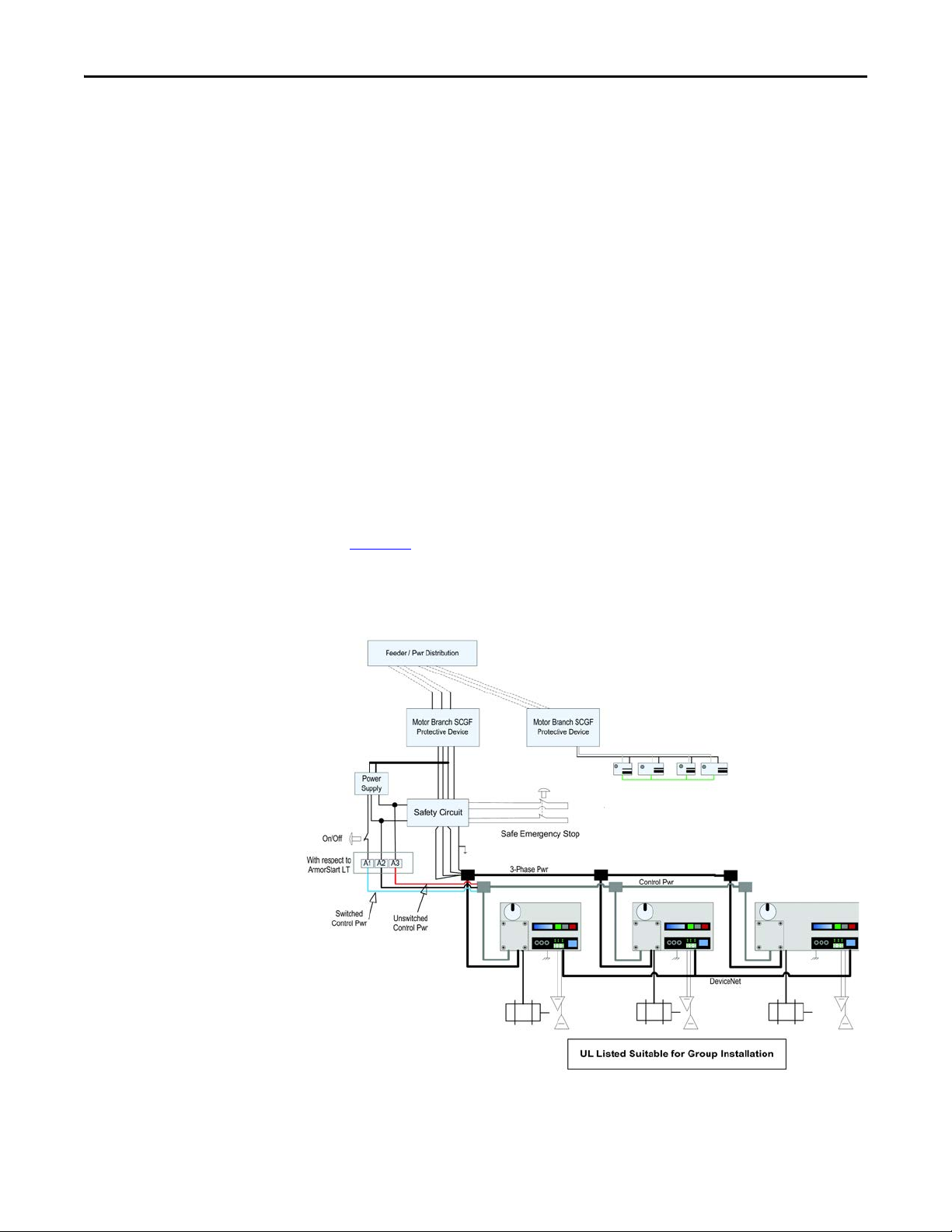
Installation and Wiring Chapter 2
Typical System Example
The primary function of ArmorStart LT is to control and protect a three-phase
squirrel cage induction motor. Three-phase power enters through terminals that
are connected to a manually operated disconnect switch. The three-phase power
may also connect internally to an optional three-phase to 24V DC power supply
(IPS). Wired in series with the disconnect is an electrically operated contactor or
a variable frequency drive. For Bulletin 294D an optional source brake contactor
may also be connected to the disconnect output terminals. The source brake
contactor is used to control an electromechanical brake physically attached to the
motor. The microcontroller and interface circuits are contained in the ECM.
The ECM also houses 6 user configurable I/O points. These six I/O points are
used for system level control and are accessible via by the communication
network or DeviceLogix.
The user has the flexibility to coordinate the appropriate safety function for their
application. ArmorStart LT does not provide a safe torque-off input. Therefore,
the safety function is configured externally from the controller and based upon
the risk assessment.
For example, the risk assessment may require a safety circuit with a high level
of performance. In this example, a safety relay with redundant safety contactors
and emergency stop function can be integrated into the machine controls.
Figure 17
Rockwell Automation supplier for additional support regarding the safety
circuit or for a risk assessment of your machinery.
below is an example of this configuration. Contact your local
Figure 17 -
Rockwell Automation Publication 290D-UM001A-EN-P - June 2012 47
Page 48

Chapter 2 Installation and Wiring
IMPORTANT
IMPORTANT
ArmorConnect Power Media
For greater flexibility and faster installations the user may also use
ArmorConnect media for a complete plug-n-play solution. This solution
provides plug-in style stop stations, as shown in Figure 18
. The ArmorConnect
power media offers both three-phase and control power cable cord set systems.
These include patchcords, receptacles, tees, reducers and accessories to be utilized
with the ArmorStart LT Distributed Motor Controller. This cable system allows
quick connections and reduced installation time by utilizing pre-manufactured
cable assemblies for more reliable connection of the three phase and
control power.
When specifying power media for use with the ArmorStart LT Distributed
Motor Controllers (Bulletin 290D/291D and Bulletin 294D) use only
ArmorConnect power media. The use of any other power media
will void the UL Listing of the motor controller.
Figure 18 - Media Diagram
A single channel Stop is pictured. It is necessary to perform a risk assessment
and determine specific application requirements.
1. DeviceNet Trunk Cable - Patchcord trunk cable with integral female or male connector on each end (example 1485C-P*N5-M5)
2. DeviceNet Mini- T-Port Tap - T-ports are used for connecting drops to the trunk line (example 1485P-P1N5-MN5KM)
3. DeviceNet Drop Cable - Drop cables and patch cords are used to connect devices to the network (example 1485G-P*M5-Z5)
4. DeviceNet Receptacle - Recepatcles are used when connections present but required (example 1485A–CXN5–M5)
5. DeviceNet Terminator - Properly designed DeviceNet networks require terminating resistors (example 1485A–T1N5)
48 Rockwell Automation Publication 290D-UM001A-EN-P - June 2012
Page 49

IMPORTANT
See the On-Machine Connectivity catalog for specific Ethernet
media components
Figure 19 - On-Machine Stop Stations
Installation and Wiring Chapter 2
Enclosure
Type Quick Connect
Plastic
Metal 24V AC/DC 800F-1MYMQ4
ArmorConnect Cable Ratings
Knockout
Type Operator
Mini Receptacle Metric Twist to Release
Illumination
Volta ge
24V AC/DC
Contact
Configuration
1 N.C./1 N.O.
Cat. No.
800F-1YMQ4
The ArmorConnect Power Media cables are rated per UL Type TC 600V 90°C
Dry 75°C Wet, Exposed Run (ER) or MTW 600V 90°C or STOOW 105°C
600V - Canadian Standards Association (CSA) STOOW 600V FT2.
For additional information regarding ArmorConnect Power Media refer
to ArmorStart LT selection guide, publication 290-SG001.
Branch Circuit Protection Requirements for ArmorConnect Three-Phase Power Media
When using ArmorConnect Three-Phase Power Media, fuses or circuit breakers
may be used for the motor branch circuit ground fault protection if properly
sized and allowed by product labeling.
Circuit Breaker:
Where ArmorStart LT is used with ArmorConnect — suitable for use on a
circuit capable of delivering not more than 10 000 RMS Symmetrical Amperes
at 480Y/277V AC maximum when protected by Cat. No. 140U-D6D3-C30
circuit breaker, refer to the Specifications
Rockwell Automation Publication 290D-UM001A-EN-P - June 2012 49
, Chapter 6.
Page 50

Chapter 2 Installation and Wiring
IMPORTANT
WARNING: The total circuit impedance including each cable assembly's own
impedance, must be low enough to ensure any short-circuit or ground fault
current that can flow through any assembly, will be large enough to operate the
magnetic trip of the Cat. No. 140U-D63-C circuit breaker. Refer to NFPA 70 and
NFPA 79 or your local electrical code for guidance in coordinating over current
protective devices and the circuit being protected.
Fusing:
Where ArmorStart LT is used with ArmorConnect — suitable for use on a
circuit capable of delivering not more than 10 000 RMS Symmetrical Amperes
(SCCR) at 480/277V AC maximum when protected by 40 A CC, J, and T
class fuses, refer to the Specifications
, Chapter 6.
Electrical Wiring
ArmorStart LT EtherNet/IP utilizes 24V DC control power for communications
and I/O. The control power terminal connections are labeled A1, A2, and A3.
Switched power (A1) will supply outputs and motor control. Unswitched
power (A3) will supply logic power, communications, and sensor inputs.
EtherNet/IP is an unpowered network, therefore if device status is important,
the A3 terminal must have an unswitched power source.
Figure 20 - Bulletin 290D Full Voltage
50 Rockwell Automation Publication 290D-UM001A-EN-P - June 2012
Page 51

Figure 21 - Bulletin 291D Full Voltage Reversing
Installation and Wiring Chapter 2
Figure 22 - Bulletin 294D VFD
Rockwell Automation Publication 290D-UM001A-EN-P - June 2012 51
Page 52

Chapter 2 Installation and Wiring
Figure 23 - Bulletin 294D VFD with -SB
Figure 24 - Bulletin 290D Full Voltage with -IPS
52 Rockwell Automation Publication 290D-UM001A-EN-P - June 2012
Page 53

Figure 25 - Bulletin 291D Full Voltage Reversing with -IPS
Installation and Wiring Chapter 2
Figure 26 - Bulletin 294D VFD with -IPS
Rockwell Automation Publication 290D-UM001A-EN-P - June 2012 53
Page 54

Chapter 2 Installation and Wiring
Figure 27 - Bulletin 294D VFD with -IPS, -SB
54 Rockwell Automation Publication 290D-UM001A-EN-P - June 2012
Page 55

Installation and Wiring Chapter 2
IMPORTANT
Group Motor Installations for USA and Canada Markets
Wiring
When ArmorStart LT is applied according to group motor installation
requirements, two or more motors of any rating or controller type, are permitted
on a single branch circuit. Group Motor Installation has been successfully used
for many years in the USA and Canada.
For additional information regarding group motor installations with the
ArmorStart LT Distributed Motor Controller, see Appendix A
Cable Workmanship Guidelines
In addition to conduit and seal-tite raceway, it is acceptable to utilize cable that is
dual rated Tray Cable Exposed Runs (TC-ER) and Cord, STOOW, for power
and control wiring on ArmorStart LT installations. In the USA and Canada
installations, the following guidance is outlined by the National Electrical Code
(NEC) and National Fire Protection Association (NFPA) 79.
In industrial establishments where the conditions of maintenance and
supervision ensure that only qualified persons service the installation, and where
the exposed cable is continuously supported and protected against physical
damage using mechanical protection, such as struts, angles, or channels, Type TC
tray cable that complies with the crush and impact requirements of Type MC
(Metal Clad) cable and is identified for such use with the marking Type TC-ER
(Exposed Run)➊ shall be permitted between a cable tray and the utilization
equipment or device as open wiring. The cable shall be secured at intervals
not exceeding 6 ft (1.8 m) and installed in a “good workman-like” manner.
Equipment grounding for the utilization equipment shall be provided
by an equipment grounding conductor within the cable.
While the ArmorStart LT is intended for installation in factory floor
environments of industrial establishments, the following must be taken into
consideration when locating the ArmorStart LT in the application:
• Cables, including those for control voltage including 24V DC and
communications, are not to be exposed to an operator or building traffic
on a continuous basis.
• Location of the ArmorStart LT to minimize exposure to continual traffic
is recommended. If location to minimize traffic flow is unavoidable, other
barriers to minimize inadvertent exposure to the cabling should be
considered.
• Routing cables should be done in such a manner to minimize inadvertent
exposure and/or damage.
• If conduit or other raceways are not used, it is recommended that strain
relief fittings be utilized when installing the cables for the control and
power wiring through the conduit openings.
➊ Historically cable meeting these crush and impact requirements was designated and marked “Open Wiring.” Cable so marked is
equivalent to the present Type TC-ER and can be used.
Rockwell Automation Publication 290D-UM001A-EN-P - June 2012 55
Page 56

Chapter 2 Installation and Wiring
Service Space
The working space around the ArmorStart LT can be minimized as the
ArmorStart LT does not require examination, adjustment, servicing or
maintenance while energized. In lieu of this service, the ArmorStart LT
is meant to be unplugged and replaced after proper lock-out/tag-out
procedures have been employed.
Hand Operation (HOA) Considerations
The Hand/Off/Auto (HOA) is a factory-installed option that the user may
select. The HOA keypad may require the ArmorStart LT to be installed as
follows, if the application requires frequent use of the hand operated interface
by the equipment operator:
1. Install not less than 2 ft (0.6 m) above the servicing level and within easy
reach of the operator, who is in a normal working position.
2. Install where the operator is not placed in a hazardous situation when
operating the equipment.
General Wiring Considerations
3. Install where the possibility of inadvertent operation is minimized.
Where inadvertent operation may cause adverse effects the HOA can be disabled
via parameter 67.
Wire in an industrial control application can be divided into three groups: power,
control, and signal. The following recommendations for physical separation
between these groups is provided to reduce the coupling effect:
• Minimum spacing between different wire groups in the same tray should
be 6 in. (16 cm).
• Wire runs outside an enclosure should be run in conduit or have shielding/
armor with equivalent attenuation.
• Different wire groups should be run in separate conduits.
• Minimum spacing between conduits containing different wire groups
should be 3 in. (8 cm).
• Minimum spacing between 3-phase power cabling and DeviceNet
or I/O cabling should be at least 6 in. (16 cm) to avoid noise issues,
unless properly shielded.
56 Rockwell Automation Publication 290D-UM001A-EN-P - June 2012
Page 57

Installation and Wiring Chapter 2
IMPORTANT
Grounding
An effectively grounded product is one that is “intentionally connected to earth
through a ground connection or connections of sufficiently low impedance and
having sufficient current-carrying capacity to prevent the buildup of voltages
which may result in undue hazard to connected equipment or to persons” (as
defined by the US National Electric Code NFPA70, Article 100B). Grounding
is done for two basic reasons: safety (defined above) and noise containment or
reduction. While the safety ground scheme and the noise current return circuit
may sometimes share the same path and components, they should be considered
different circuits with different requirements.
Grounding Safety Grounds
The object of safety grounding is to ensure that all metalwork is at the same
ground (or Earth) potential at power frequencies. Impedance between the drive
and the building scheme ground must conform to the requirements of national
and local industrial safety regulations or electrical codes. These will vary based
on country, type of distribution system and other factors. Periodically check the
integrity of all ground connections.
General safety dictates that all metal parts are connected to earth with separate
copper wire or wires of the appropriate gauge. Most equipment has specific
provisions to connect a safety ground or PE (protective earth) directly to it.
Grounding PE or Ground
The safety ground - PE must be connected to earth ground. This point must
be connected to an adjacent building steel (girder, joist), a floor ground rod, a bus
bar or a building ground grid. Grounding points must comply with national and
local industrial safety regulations or electrical codes. Some codes may require
redundant ground paths and periodic examination of connection integrity.
To avoid electrolytic corrosion on the external earth terminal, avoid spraying
moisture directly on the terminal. When used in washdown environments
apply a sealant or other corrosion inhibitor on the external ground terminal
to minimize any negative effects of galvanic or electro-chemical corrosion.
Ground connections should be inspected on a regular basis.
Grounding Motors
The motor frame or stator core must be connected directly to the PE connection
with a separate ground conductor. It is recommended that each motor frame be
grounded to building steel at the motor.
Rockwell Automation Publication 290D-UM001A-EN-P - June 2012 57
Page 58

Chapter 2 Installation and Wiring
Power Distribution
The type of transformer and the connection configuration feeding an
ArmorStart LT Bulletin 294D plays an important role in its performance
and safety.
Delta/Wye with Grounded Wye Neutral
Figure 28 -
Del ta/Wy e with Groun ded Wye Neutral is the most common type of
distribution system. The grounded neutral provides a direct path for common
mode current caused by the drive output.
AC Line Voltage
Line Reactor
SHOCK HAZARD: ArmorStart LT requires the use of grounded Wye
power systems.
Incoming voltage imbalances greater than 2% can cause large unequal currents
in a drive. An input line reactor may be necessary when line voltage imbalances
are greater than 2%.
In general, ArmorStart LT does not require line reactors. In most applications,
the ArmorStart LT is further away from the power distribution panel, therefore
the length of cable provides additional impedance as compared to an in-panel
solution.
Through design and engineering, the need for a line reactor is significantly
reduced.
Therefore, ArmorStart LT does not define a minimum line impedance
specification, and does not require a line reactor. Its design trades the external
reactor supplied by the customer for an internal fan integral to the controller.
This improves the overall life of the product. To achieve maximum electrical life
of Bulletin 294, an 800μH line reactor for the group can be applied to extend
total service life.
58 Rockwell Automation Publication 290D-UM001A-EN-P - June 2012
Page 59

Installation and Wiring Chapter 2
In addition, if line disturbance mitigation is also necessary, the ArmorStart LT is
equipped with an EMI filter and when used with a shielded motor cable reduces
the impact of the power switching components. For CE compliant installations
refer to the recommended EMI/RFI cord grip accessory or quick disconnect
shielded motor cable. Contact your local sales representative for details.
If however, the customer specifications require input line reactors or transformers,
the recommendation is to group the ArmorStarts at the distribution panel under
one line reactor (not individual reactors or transformers). Keep in mind where
full voltage ArmorStarts are included with VFD ArmorStarts, the starting
currents of the full voltage ArmorStarts can be significant. The current must be
accounted for in the selection of the line reactor or you run the risk of nuisance
undervoltage faults of the VFD ArmorStarts while the full voltage ArmorStarts
are starting their motors.
ATT EN TI ON : For 50°C ambients ArmorStart LT must be derated and applied
with a minimum of 800 uH to1200 uH line reactor. Failure to follow this
application requirement will result in premature product failure. Contact your
local Rockwell Automation representative for assistance.
Bulletin 294D Motor Cable Considerations
The majority of recommendations regarding drive cable address issues are caused
by the nature of the drive output. A PWM drive creates AC motor current by
sending DC voltage pulses to the motor in a specific pattern. These pulses
affect the wire insulation and can be a source of electrical noise. The rise time,
amplitude, and frequency of these pulses must be considered when choosing a
wire/cable type. The choice of cable must consider:
1. The effects of the drive output once the cable is installed
2. The need for the cable to contain noise caused by the drive output
3. The amount of cable charging current available from the drive
4. Possible voltage drop (and subsequent loss of torque)
for long wire runs
Keep the motor cable lengths less than 45 ft from the ArmorStart LT.
Unshielded Cable
Properly designed multi-conductor cable can provide superior performance
in wet applications, significantly reduce voltage stress on wire insulation and
reduce cross coupling between drives.
The use of cables without shielding is generally acceptable for installations
where electrical noise created by the drive does not interfere with the operation
of other devices such as: communications cards, photoelectric switches, weigh
scales, and others. Be certain the installation does not require shielded cable
Rockwell Automation Publication 290D-UM001A-EN-P - June 2012 59
Page 60

Chapter 2 Installation and Wiring
G
R
B
W
Filler PVC Outer
Sheath
Single Ground
Conductor
Shield
Drain Wire
to meet specific EMC standards for CE, C-Tick or FCC. Cable specifications
depend on the installation type.
Figure 29 - Unshielded Multi-Conductor Cable
Shielded Cable
Shielded cable contains all of the general benefits of multi-conductor cable
with the added benefit of a copper braided shield that can contain much
of the noise generated by a typical AC Drive. Strong consideration for shielded
cable should be given for installations with sensitive equipment such as weigh
scales, capacitive proximity switches, and other devices that may be affected
by electrical noise in the distribution system. Applications with large numbers
of drives in a similar location, imposed EMC regulations, or a high degree
of communications/networking are also good candidates for shielded cable.
An acceptable shielded cable will have 4 XLPE insulated conductors with a
100% coverage foil and an 85% coverage copper braided shield (with drain wire)
surrounded by a PVC jacket.
Figure 30 - Shielded Cable with Four Conductors
W
G
R
B
Recommended Cable Connectors/Glands
Choose cable connectors or glands that offer the best cable protection, shield
termination, and ground contact.
60 Rockwell Automation Publication 290D-UM001A-EN-P - June 2012
Page 61

Installation and Wiring Chapter 2
Recommended Cord Grips
The following are recommended cord grips to be used
for ArmorStart LT installations.
Table 9 - Cord grip for Motor, Power, and Control
Recommended Thomas and Betts Cord Grips for G1 and G3 Glands.
Thomas and Betts Part Nos.
Description Gland
Motor/Source Brake G1 0.75 in. 0.500…0.750 2932NM 5263 142TB
Motor/Source Brake G1 0.75 in. 0.660…0.780 2675 5263 142TB
Power G1 1.0 in. 0.660…0.780 2676 5264 143
Power G1 1.0 in. 0.770…0.895 2677 5264 143
Control Power, Motor/Source
Brake
3-Phase Power G3 M25 0.512…0.709 CC-ISO25-G – GMN-M25
Knockout
Size Cable Diameter Range (in.2)
G3 M20 0.236…0.473 CC-ISO20-G – GMN-M20
Cord Grip
Sealing
Ring
Lock Nut
Shield Terminating Connectors
The cable connector selected must provide good 360o contact and low transfer
impedance from the shield or armor of the cable to the conduit entry plate at
both the motor and the ArmorStart LT for electrical bonding. SKINTOP
MS-SC/MS-SCL cable grounding connectors and NPT/PG adapters from
LAPPUSA are good examples of this type of shield terminating gland.
®
Rockwell Automation Publication 290D-UM001A-EN-P - June 2012 61
Page 62

Chapter 2 Installation and Wiring
U (T1)
V (T2)
W (T3)
PE
One or More
Ground Leads
Braid wires pulled back in a 360° pattern
around the ground cone of the connector
Drain wires pulled back in a 360° pattern
around the ground cone of the connector
Metal locknut bonds the
connector to the panel
Metal connector body
makes direct contact with
the braid wires
ATTENTION: Shielded connector or motor cable is mandatory for CE compliant
installations.
Ground Bushing
Figure 31 - Terminating the Shield with a Connector
Electromagnetic Compatibility (EMC)
The following guidelines are provided for EMC installation compliance.
General Notes (Bulletin 294D only)
• The motor cable should be kept as short as possible in order to avoid
electromagnetic emissions as well as capacitive currents. CE conformity
of ArmorStart LT with EMC directive does not guarantee the entire
machine installation complies with CE EMC requirements. Many
factors can influence total machine/installation compliance.
• The EMI filter may result in relatively high ground leakage currents.
Therefore, ArmorStart LT must only be applied in installations that are
solidly grounded (bonded) to the building power distribution ground.
62 Rockwell Automation Publication 290D-UM001A-EN-P - June 2012
Page 63

Installation and Wiring Chapter 2
Pin 1 – Drain (no connection)
Pin 2 – +VDNET
Pin 3 – -VDNET
Pin 4 – CAN_H
Pin 5– CAN_L
4
3
Ethernet/IP Connector D-coded (M12)
M12 Female Ethernet Connector
Pin 1 – Tx+
Pin 2 – Rx+
Pin 3 – Tx–
Pin 4 – Rx–
I/O Connector (M12)
Pin 1 – Sensor Source Voltage
Pin 2 – Not Used
Pin 3 – Common
Pin 4 – Input or Output
Pin 5 – Not Used
ATTENTION: RFI Filter Grounding. Due to the presence of an integral EMI
filter, this product may draw more that 3.5 mA of leakage current. The controller
must only be used in installations with grounded AC supply systems and be
permanently installed and solidly grounded (bonded) to the building power
distribution ground. Grounding should not include any form of plug or socket
that would permit inadvertent disconnection. Consult your local codes
regarding redundant ground connections and/or size of protective earthing
conductor. The integrity of all connections should be periodically checked.
Ethernet, DeviceNet, and I/O Connections
DeviceNet Connector (M18)
Rockwell Automation Publication 290D-UM001A-EN-P - June 2012 63
Page 64

Chapter 2 Installation and Wiring
Pin 1 - T1 (black)
Pin 2 - T2 (white)
Pin 3 - T3 (red)
Pin 4 - Ground (green/yellow)
Pin 1 - Ground (green/yellow)
Pin 2 - B1(black)
Pin 3 -B2 (white)
Pin 1 – (+V) Unswitched (A3/red)
Pin 2 – (–V) Common (A2/black)
Pin 3 – Not used (green)
Pin 4 – Not used (blank)
Pin 5 – (+V) Switched (A1/blue)
Pin 6 – Not used (white)
Pin 1 - L1 (black)
Pin 2 - L2 (white)
Pin 3 - L3 (red)
Pin 4 - Ground (green/yellow)
ArmorConnect Power Media Receptacles
ArmorStart LT utilizes a M22 male receptacle for power inputs and a M22
female receptacle for motor or motor brake output.
Motor Connector (optional)
Source Brake Connector (optional)
Incoming Control Power (optional) – 24V DC Only
Incoming Three-Phase Power (optional)
64 Rockwell Automation Publication 290D-UM001A-EN-P - June 2012
Page 65

Installation and Wiring Chapter 2
Optional Locking Clip
The locking clip is an optional device that can be used, if desired. The clam shell
design clips over power quick disconnect connections to limit customer access to
disconnection.
Figure 32 -
SHOCK HAZARD: DO NOT connect or disconnect power or motor connections
while power is applied to ArmorStart LT. Proper Lock-Out Tag-Out procedures
should be followed to reduced the risk of severe injury.
SHOCK HAZARD: The ArmorStart LT local disconnect will only isolate the motor
power and remove switched power when turned OFF. Power inputs must be
switched OFF properly from their respective sources before connection or
disconnection of incoming power. Proper Lock-Out Tag-Out procedures should
be followed to reduced the risk of severe injury.
Rockwell Automation Publication 290D-UM001A-EN-P - June 2012 65
Page 66

Chapter 2 Installation and Wiring
Notes:
66 Rockwell Automation Publication 290D-UM001A-EN-P - June 2012
Page 67

Product Commissioning
Chapter 3
Configuring DeviceNet Address
The ArmorStart® is shipped with a default switch setting of 99 and Autobaud
enabled. When a value greater than 63 is read, then the node address will be set to
the value stored in memory. From the factory the node address will be set to 63.
The Each device on a DeviceNet network must have a unique node address
which can be set to a value from 0 to 63. Keep in mind that most DeviceNet
systems use address 0 for the master device (Scanner) and node address 63 should
be left vacant for introduction of new slave devices. The ArmorStart offers two
methods for node commissioning .The node address for a device can be changed
using software or by setting hardware switches that reside on electronic control
module (ECM). While both methods yield the same result, it is good practice to
choose one method and deploy it throughout the system. For software
configuration ensure that the node address is set to 99 and use RS Networx node
commissioning wizard.
Manually Configure the Network Address Switches
Remove the protective caps from the rotary switches.
Figure 33 - Switches on the I/O module
Set the network address by adjusting the two rotary switches on the front
of the ECM.
Rockwell Automation Publication 290E-UM001B-EN-P - June 2012 67
Page 68

Chapter 3 Product Commissioning
This example shows the
node address set to 00.
IMPORTANT
Figure 34 - Network Address Example
The switch value of 88 allows the user to reset to factory default configuration
including configuration parameters. This setting is useful in situations where the
user wishes to decommission a module or when the user wishes to commission a
previously-used module that has an unknown configuration. When the switches
are set to 888, upon the next power cycle the ArmorStart LT will return to
factory default settings and cease all communications. The Module Status LED
shall transition to blinking red and the Network Status LED shall transition
to off.
After reset, the user will then need to change the IP address to a valid setting and
power cycle. The purpose of this is to prevent the user from resetting the module
and then never changing the switch setting from 88.
Setting the node address to “88” followed by a power cycle will reset the device to its factory default configuration.
To r esum e network c ommunication the address MUST
be set to a valid address and power cycled again.
68 Rockwell Automation Publication 290E-UM001B-EN-P - June 2012
Page 69

DeviceNet™ Commissioning
Product Commissioning Chapter 3
Establishing a DeviceNet Node Address
Node Commissioning using Hardware
The ArmorStart® LT is shipped with a default node address of 63 and Autobaud
enabled. Each device on a DeviceNet network must have a unique node address
or MAC ID which can be set to a value from 0 to 63. Keep in mind that most
DeviceNet systems use address 0 for the master device (Scanner) and node
address 63 should be left vacant for introduction of new slave devices. The
ArmorStart offers two methods for node commissioning as shown below.
The node address for a device can be changed using software or by setting
hardware switches that reside on the back of the control module. While both
methods yield the same result, it is good practice to choose one method and
deploy it throughout the system.
The ArmorStart is shipped with the hardware rotary switches set to a value of
(99). If the switches are set to a value (64) or above, the device will automatically
configure itself to the software node address. If the switches are set to a value of
(63) or less, the device will be at the node address designated by the switch
configuration.
To set an address using the hardware rotary switches, simply set the switches to
the desired node address and cycle power to the unit. The Device will re-start at
the new address.
Node Commissioning using Software
To set the node address of the ArmorStart using software or other handheld
tools, leave the hardware switches in there default position (99) or insure that
they are set to something greater than (63). With the hardware switches set, use
the software or handheld tool to change the address.
To begin the configuration of ArmorStart using software, execute the
RSNetWorx™ software and complete the following procedure. You must use
RSNetWorx Revision 11 or later.
Rockwell Automation Publication 290E-UM001B-EN-P - June 2012 69
Page 70

Chapter 3 Product Commissioning
1. Go on-line using RSNetWorx for DeviceNet. This can be accomplished by
selecting the Network menu, and then choosing RSWho.
2. Choose the appropriate DeviceNet PC interface.
Note: DeviceNet drivers must be configured using RSLinx prior to being
available to RSNetWorx.
3. Click OK.
4. RSNetWorx will notify the user to upload or download devices before
viewing configuration. Click OK.
5. RSNetWorx will now browse the network and display all of the nodes it
has detected on the network. For some versions of RSNetWorx software
the ArmorStart EDS files and icon may not be included and will show up
as an “Unregistered Device”. Refer to Registering an EDS file for details.
70 Rockwell Automation Publication 290E-UM001B-EN-P - June 2012
Page 71

Product Commissioning Chapter 3
6. If RSNetWorx recognizes the device as an ArmorStart LT, skip ahead to
the following section Changing the Node address (MAC ID)
Registering an EDS file
The EDS file defines how RSNetWorx for DeviceNet will communicate to the
ArmorStart. Follow the steps below to build and register the EDS file.
To register a device you must first obtain the EDS file from the following web
page: http://www.ab.com/networks/eds
You are also able to upload the eds directly from the product if online.
After obtaining the files do the following:
1. Right mouse click on the “Unrecognized Device” icon and choose
Register Device from the menu.
2. Click Next. The following screen appears:
3. Choose “Register an EDS file(s)” as shown above and then click the Next
button.
4. Choose to “Register a single file”
specify the file name or location using the Browse button to locate the
EDS file on your computer.
Rockwell Automation Publication 290E-UM001B-EN-P - June 2012 71
or "Register a directory of EDS files" and
Page 72

Chapter 3 Product Commissioning
5. Click the Next button.
6. The following screen will display any warning or errors if a problem occurs
while registering the file. If a problem occurs insure that you have the
correct file and try again. Click the Next button when no errors occur.
7. Click the Next button
72 Rockwell Automation Publication 290E-UM001B-EN-P - June 2012
Page 73

Product Commissioning Chapter 3
Using the Node Commissioning Tool Inside RSNetWorx for DeviceNet
8. Click the Finish button. After a short while RSNetWorx will update your
online screen by replacing the unrecognized device with the name and icon
given by the EDS file you have just registered.
1. Choose “Node Commissioning” from the “To o l s ” menu at the top of the
screen.
2. Clicking on Browse… will prompt a screen similar to the one below to
appear.
Rockwell Automation Publication 290E-UM001B-EN-P - June 2012 73
Page 74

Chapter 3 Product Commissioning
3. Select the ArmorStart located at node 63, and then click OK. The node
commissioning screen will have the “Current Device Settings” entries
completed. It will also provide the current network baud rate in the “New
ArmorStart Settings” area. Do not change the baud rate unless you
absolutely sure that this value needs to be changed.
4. Enter the desired node address in the “New Device Settings” section. In
this example, the new node address is 5. Click Apply to apply the new node
address.
5. When the new node address has been successfully applied, the “Current
Device Settings” section of the window is updated as follows. If an error
occurs, check to make sure the device is properly powered up and
connected to the network.
6. Click Close to exit the node commissioning tool.
7. Choose “Single Pass Browse” from the “Network” menu to update
RSNetWorx and verify that the node address is set correctly.
74 Rockwell Automation Publication 290E-UM001B-EN-P - June 2012
Page 75

Product Commissioning Chapter 3
IMPORTANT
System Configuration
Selection of produced and consumed I/O assemblies (sometimes referred to as
input and output assemblies) define the format of I/O message data that is
exchanged between the ArmorStart and other devices on the network. The
consumed information is generally used to command the state of its outputs, and
produced information typically contains the state of the inputs and the current
fault status of the device.
The default consumed and produced assemblies are shown below; for additional
formats refer to Appendix B. The ArmorStart default configuration varies
depending on the type of starter.
Choosing the size and format of the I/O data that is exchanged by the
ArmorStart is done by choosing a consumed assembly instance number. This
instance number is written to the Consumed IO Assy parameter. The different
instances/formats allow user programming flexibility and network optimization.
The Consumed and Produced IO Assy parameter values can not be changed
while the ArmorStart is online with a scanner. Any attempts to change the
value of this parameter while online with a scanner will result in the error
message “Object State Conflict”.
Rockwell Automation Publication 290E-UM001B-EN-P - June 2012 75
Page 76

Chapter 3 Product Commissioning
Table 10 - Default Consume Assembly for Bulletin 294D
Instance 154 “Drive Cmd” – Default Consumed Assembly for 294 Sta rters
ByteBit 7Bit 6Bit 5Bit 4Bit 3Bit 2Bit 1Bit 0
0 JogReverse JogForward ResetFault RunReverse RunForward
1 Decel2 Accel2 Out05 Out04 Out03 Out02 Out01 Out00
2 CommandFreq (Low) (xxx.x Hz)
3 CommandFreq (High) (xxx.x Hz)
4 Pt07D eviceIn Pt06DeviceIn Pt05DeviceIn Pt04DeviceIn Pt03DeviceIn Pt02Dev iceIn P t01DeviceIn Pt00DeviceIn
5 Pt15D eviceIn Pt14DeviceIn Pt13DeviceIn Pt12DeviceIn Pt11DeviceIn Pt10Dev iceIn P t09DeviceIn Pt08DeviceIn
6 AnalogDeviceIn (low byte)
7 AnalogDeviceIn (high byte)
Table 11 - Default Compact Produce Assembly for Bulletin 294D
Instance 155 “Compact Status” - Compact Produced A ssembly for 294D Starters
ByteBit 7Bit 6Bit 5Bit 4Bit 3Bit 2Bit 1Bit 0
0 AtReference NetRefStatus NetControlStatus Ready RunningReverse RunningForward WarningPresent TripPresent
1 BrakeStatus Disconnec tClosed KeyPadJogging KeyPadHand KeyPadOff KeyPadAuto DLXEnabled
2 OutputFrequency (Low) (xxx.x Hz)
3 OutputFrequency (High) (xxx.x Hz)
4 Pt05 Pt04 Pt03 Pt02 Pt01 Pt00
5
6 Pt07DeviceOut Pt06DeviceOut Pt0 5DeviceOut Pt04DeviceOut Pt03DeviceOut Pt02DeviceOut Pt001DeviceOut Pt00DeviceOut
7 Pt15DeviceOut Pt14DeviceOut Pt1 3DeviceOut Pt12DeviceOut Pt11DeviceOut Pt10DeviceOut Pt09D eviceOut P t08DeviceOut
76 Rockwell Automation Publication 290E-UM001B-EN-P - June 2012
Page 77

Table 12 - Bulletin 294D Produced Assembly Status Tags
Table 13 - Bulletin 294D Consume Assembly/Command Tag Explanation
Device Output Command Tags Tag Description/Use
RunForward Command VFD forward
RunReverse Command VFD reverse
ResetFault Fault reset
JogForward Command Jog forward per internal frequency
JogReverse Command Jog reverse per internal frequency
Pt00Data If user defined as output, commnd output ON
Pt01Data If user defined as output, commnd output ON
Pt02Data If user defined as output, commnd output ON
Pt03Data If user defined as output, commnd output ON
Pt04Data If user defined as output, commnd output ON
Pt05Data If user defined as output, commnd output ON
Accel2 VFD acce leration ramp 2
Decel2 VFD deceleration ramp 2
FreqCommand Logix command frequency
Pt00DeviceIn Network input to DeviceLogix engine
Pt01DeviceIn Network input to DeviceLogix engine
Pt02DeviceIn Network input to DeviceLogix engine
Pt03DeviceIn Network input to DeviceLogix engine
Pt04DeviceIn Network input to DeviceLogix engine
Pt05DeviceIn Network input to DeviceLogix engine
Pt06DeviceIn Network input to DeviceLogix engine
Pt07DeviceIn Network input to DeviceLogix engine
Pt08DeviceIn Network input to DeviceLogix engine
Pt09DeviceIn Network input to DeviceLogix engine
Pt10DeviceIn Network input to DeviceLogix engine
Pt11DeviceIn Network input to DeviceLogix engine
Pt12DeviceIn Network input to DeviceLogix engine
Pt13DeviceIn Network input to DeviceLogix engine
Pt14DeviceIn Network input to DeviceLogix engine
Pt15DeviceIn Network input to DeviceLogix engine
Int00DeviceIn Network analog input to DeviceLogix engine
Product Commissioning Chapter 3
Table 14 - Bulletin 294E Produced Assembly/Status Tag Explanation
Device Input Status Tags Tag Description/Use
Fault Communication fault between PLC and device (all 1s = fault, all 0s = normal)
TripPresent Fault exists within unit
WarningPresent Warning of potential fault
RunningForward Motor commanded to run forward
RunningReverse Motor commanded to run reverse
Ready Control and 3-phase power present
NetworkControlStatus Start and Stop command comes from network (PLC or Connected Explicit Messaging)
Rockwell Automation Publication 290E-UM001B-EN-P - June 2012 77
Page 78

Chapter 3 Product Commissioning
Device Input Status Tags Tag Description/Use
NetworkReferenceStatus Speed reference comes from the network (not DeviceLogix)
AtRefere nce At com manded speed reference
DeviceLogixEnabled DeviceLogix is enabled
KeypadAuto HOA is in Auto mode
KeypadOff HOA is in Off mode
KeypadHand HOA is in Hand mode
KeypadJogging HOA is in Jog mode
DisconnectClosed Disconnect is closed
BrakeContactorStatus Source brake contactor status (1 = close, 0 = open)
OutputFrequency VFD frequency
Pt00Data User-configured I/O status
Pt01Data User-configured I/O status
Pt02Data User-configured I/O status
Pt03Data User-configured I/O status
Pt04Data ASLT_DEMO:I.Pt04Data
Pt05Data User-configured I/O status
Pt00DeviceOut DeviceLogix network output status
Pt01DeviceOut DeviceLogix network output status
Pt02DeviceOut DeviceLogix network output status
Pt03DeviceOut DeviceLogix network output status
Pt04DeviceOut DeviceLogix network output status
Pt05DeviceOut DeviceLogix network output status
Pt06DeviceOut DeviceLogix network output status
Pt07DeviceOut DeviceLogix network output status
Pt08DeviceOut DeviceLogix network output status
Pt09DeviceOut DeviceLogix network output status
Pt10DeviceOut DeviceLogix network output status
Pt11DeviceOut DeviceLogix network output status
Pt12DeviceOut DeviceLogix network output status
Pt13DeviceOut DeviceLogix network output status
Pt14DeviceOut DeviceLogix network output status
Pt15DeviceOut DeviceLogix network output status
Int00DeviceOut DeviceLogix network analog output
OutputCurrent VFD output current — Parameter 3
OutputVoltage VFD output voltage — Parameter 4
DCBusVoltage VFD DC bus voltage — Parameter 5
SwitchedVoltageLevel Switched control power voltage — Parameter 11
UnswitchedVoltageLevel Unswitched control power voltage — Parameter 12
InternalFanRPM VFD fan speed — Parameter 13
OperatingHours Elapse run hours — Parameter 14
DriveTemperature VFD internal tem perature — Parameter 15
TripStatus Bit enumerate trip status — Parameter 16
WarningStatus Bit enumerate warning status — Parameter 17
78 Rockwell Automation Publication 290E-UM001B-EN-P - June 2012
Page 79

Product Commissioning Chapter 3
Table 15 - Default Consume Assembly for Bulletin 290D/291D
Instance 150 “Starter Cmd” - DeviceLogix Consumed Assembly for 290D / 291D Starters
ByteBit 7Bit 6Bit 5Bit 4Bit 3Bit 2Bit 1Bit 0
0 ResetFault RunReverse RunForward
1 Out05 Out04 Out03 Out02 Out01 Out00
2 Pt07D eviceIn Pt06DeviceIn Pt05DeviceIn Pt04DeviceIn Pt03DeviceIn Pt02Dev iceIn P t01DeviceIn Pt00DeviceIn
3 Pt15D eviceIn Pt14DeviceIn Pt13DeviceIn Pt12DeviceIn Pt11DeviceIn Pt10Dev iceIn P t09DeviceIn Pt08DeviceIn
4 AnalogDeviceIn (low byte)
5 AnalogDeviceIn (high byte)
Rockwell Automation Publication 290E-UM001B-EN-P - June 2012 79
Page 80

Chapter 3 Product Commissioning
Table 16 - Default Produce Compact Assembly for Bulletin 290D/291D
Instance 151 “Compact Status” - Compact Produced Assembly for 290D / 291D Starters
ByteBit 7Bit 6Bit 5Bit 4Bit 3Bit 2Bit 1Bit 0
0 CurrentFlowing NetControlStatus Ready RunningReverse RunningForward WarningPresent TripPresent
1 DisconnectClosed KeyPadHand KeyPadOff KeyPadAuto DLXEnabled
2 Pt05 Pt04 Pt03 Pt02 Pt01 Pt00
3
4 Pt07DeviceOut Pt06DeviceOut Pt0 5DeviceOut Pt04DeviceOut Pt03DeviceOut Pt02DeviceOut Pt01D eviceOut P t00DeviceOut
5 Pt15DeviceOut Pt14DeviceOut Pt1 3DeviceOut Pt12DeviceOut Pt11DeviceOut Pt10DeviceOut Pt09D eviceOut P t08DeviceOut
80 Rockwell Automation Publication 290E-UM001B-EN-P - June 2012
Page 81

Product Commissioning Chapter 3
The following table provides a brief explanation for the tag function:
Table 17 - Bulletin 290D/291D Consume Assembly Command Tag Explanation
Device Output Command Tags Tag Description/Use
RunForward Command VFD forward
RunReverse Command VFD reverse
ResetFault Fault reset
Pt00Data If user defined as output, commnd output ON
Pt01Data If user defined as output, commnd output ON
Pt02Data If user defined as output, commnd output ON
Pt03Data If user defined as output, commnd output ON
Pt04Data If user defined as output, commnd output ON
Pt05Data If user defined as output, commnd output ON
Pt00DeviceIn Network input to DeviceLogix engine
Pt01DeviceIn Network input to DeviceLogix engine
Pt02DeviceIn Network input to DeviceLogix engine
Pt03DeviceIn Network input to DeviceLogix engine
Pt04DeviceIn Network input to DeviceLogix engine
Pt05DeviceIn Network input to DeviceLogix engine
Pt06DeviceIn Network input to DeviceLogix engine
Pt07DeviceIn Network input to DeviceLogix engine
Pt08DeviceIn Network input to DeviceLogix engine
Pt09DeviceIn Network input to DeviceLogix engine
Pt10DeviceIn Network input to DeviceLogix engine
Pt11DeviceIn Network input to DeviceLogix engine
Pt12DeviceIn Network input to DeviceLogix engine
Pt13DeviceIn Network input to DeviceLogix engine
Pt14DeviceIn Network input to DeviceLogix engine
Pt15DeviceIn Network input to DeviceLogix engine
Int00DeviceIn Network analog input to DeviceLogix engine
Rockwell Automation Publication 290E-UM001B-EN-P - June 2012 81
Page 82

Chapter 3 Product Commissioning
Table 18 - Bulletin 290D/291D Produced Assembly Status Tag Explanation
Device Input Status Tags Tag Description/Use
Fault Communication fault between PLC and device (all 1s = fault, all 0s = normal)
TripPresent Fault exists within unit
WarningPresent Warning of potential fault
RunningForward Motor commanded to run forward
RunningReverse Motor commanded to run reverse
Ready Control and 3-phase power present
Current Flowing Cur rent is pas sing to mo tor
DeviceLogixEnabled DeviceLogix is enabled
KeypadAuto HOA is in Auto mode
KeypadOff HOA is in Off mode
KeypadHand HOA is in Hand mode
DisconnectClosed Disconnect is closed
Pt00Data User-configured I/O status
Pt01Data User-configured I/O status
Pt02Data User-configured I/O status
Pt03Data User-configured I/O status
Pt04Data ASLT_DEMO:I.Pt04Data
Pt05Data User-configured I/O status
Pt00DeviceOut DeviceLogix network output status
Pt01DeviceOut DeviceLogix network output status
Pt02DeviceOut DeviceLogix network output status
Pt03DeviceOut DeviceLogix network output status
Pt04DeviceOut DeviceLogix network output status
Pt05DeviceOut DeviceLogix network output status
Pt06DeviceOut DeviceLogix network output status
Pt07DeviceOut DeviceLogix network output status
Pt08DeviceOut DeviceLogix network output status
Pt09DeviceOut DeviceLogix network output status
Pt10DeviceOut DeviceLogix network output status
Pt11DeviceOut DeviceLogix network output status
Pt12DeviceOut DeviceLogix network output status
Pt13DeviceOut DeviceLogix network output status
Pt14DeviceOut DeviceLogix network output status
Pt15DeviceOut DeviceLogix network output status
Int00DeviceOut DeviceLogix network analog output
L1Current Phase A current
L2Current Phase B current
L3Current Phase C current
AvgCurrent Average phase A, B, and C current
PercentTCU Overload percentage thermal utilization (100% = overload trip)
SwitchedVoltageLevel Switched control power voltage — Parameter 11
82 Rockwell Automation Publication 290E-UM001B-EN-P - June 2012
Page 83

Device Input Status Tags Tag Description/Use
UnswitchedVoltageLevel Unswitched control power voltage — Parameter 12
TripStatus Bit enumerate trip status — Parameter 16
WarningStatus Bit enumerate warning status — Parameter 17
Product Commissioning Chapter 3
Rockwell Automation Publication 290E-UM001B-EN-P - June 2012 83
Page 84

Chapter 3 Product Commissioning
Notes:
84 Rockwell Automation Publication 290E-UM001B-EN-P - June 2012
Page 85

Bulletin 290D/291D/294D
IMPORTANT
Programmable Parameters
Chapter 4
Electronic Data Sheet (EDS)
Basic Setup Parameters
An embedded EDS file can be uploaded directly from the ArmorStart LT. EDS
files are also available on the internet at: http://www.ab.com/networks/eds
Table 19 lists the minimum setup configurations required for Bulletin 290D/
291D or Bulletin 294D.
RSLogix 5000 is the recommended commissioning software. Download the AddOn-Profile (AOP) from http://support.rockwellautomation.com/controlflash/Logix
Profiler.asp for additional functionality. There are additional capabilities that are
not enabled or left at their default values.
Table 19 - Quick Parameter Setup
Bulletin 290D/291D Bulletin 294D
28 FLASetting
29 OLResetLevel
30 OverloadClass
49 IOPointConfiguration
28 MotorNPVolts
29 MotorNPHertz
30 MotorOLCurrent
32 StopMode
34 MinimumFreq
35 MaximumFreq
36 AccelTime1
37 DecelTime1
49 IOPointConfiguration
.
All I/O points are configured as inputs, by default. Identify which points
are outputs, when needed for proper operation, using parameter 49
[IOPointConfiguration].
Rockwell Automation Publication 290D-UM001A-EN-P - June 2012 85
Page 86

Chapter 4 Bulletin 290D/291D/294D Programmable Parameters
Parameter Groups
Bulletin
290D/291D Units
1 PhaseL1Current
2 PhaseL2Current
3 PhaseL3Current
4 AverageCurrent
5%ThermalUtilized
6 StarterStatus
7 StarterCommand
8 AuxIOStatus
9 NetworkStatus
10 DLXControlStatus
11 OutputSourceV
12 SensorSourceV
13 Reserved
14 Reserved
15 Reserved
Bulletin 294D Units
Basic Status Trip Status Basic Config
1 OutputFreq
2 CommandFreq
3 OutputCurrent
4 OutputVoltage
5 DCBusVoltage
6 StarterStatus
7 StarterCommand
8 AuxIOStatus
9 NetworkStatus
10 DLXControlStatus
11 OutputSourceV
12 SensorSourceV
13 InternalFanRPM
14 ElapsedRunTime
15 DriveTemperature
16 TripStatus
17 Warni ngSt atus
18 Tri pLo g0
19 Tri pLo g1
23 SnapShotL1Amps
24 SnapShotL2Amps
25 SnapShotL3Amps
26 SnapShotAvgAmps
27 SnapShot%Thermal
Common to Bulletin 290D/291D
and Bulletin 294D Units
Bulletin
290D/291D Units
Trip Status
20 Tri pLo g2
21 Tri pLo g3
22 Tri pLo g4
Bulletin 294D Units
23 SnapShotOutFreq
24 SnapShotOutAmps
25 SnapShotOutVolts
26 SnapShotBusVolts
27 SnapShotDrvTemp
28 FLASetting
29 OLResetLevel
30 OverloadClass
31…40 Reserved
Bulletin
290D/291D Units
86 Rockwell Automation Publication 290D-UM001A-EN-P - June 2012
Page 87

Bulletin 290D/291D/294D Programmable Parameters Chapter 4
Bulletin 294D Units
Common to Bulletin 290D/291D
and Bulletin 294D Units
Motor and Control Speed Control Starter Protection User I/O Config. Miscellaneous Config.
28 MotorNPVolts
29 MotorNPHertz
30 MotorOLCurrent
31 CurrentLimit
32 StopMode
33 SpeedReference
34 MinimumFreq
35 MaximumFreq
36 AccelTime1
37 DecelTime1
38 SCurvePercent
39 JogFrequency
40 JogAccelDecel
41 ProtFltResetMode
42 ProtectFltEnable
43 WarningEnable
44 ProtectFltReset
45 RunNetFltAction
46 RunNetFaultValue
47 RunNetIdleAction
48 RunNetIdleValue
49 IOPointConfigure
50 FilterOffOn
51 FilterOnOff
52 OutProtFltState
53 OutProtFltValue
54 OutNetFaultState
55 OutNetFaultValue
56 OutNetIdleState
64 NetworkOverride
65 CommsOverride
66 KeypadMode
67 KeypadDisable
68 SetToDefaults
57 OutNetIdleValue
58 Input00Function
59 Input01Function
60 Input02Function
61 Input03Function
62 Input04Function
63 Input05Function
Bulletin
290D/291D Units
Bulletin 294D Units Network Group ZIP Group
Advanced Config.
69 OLWarningLevel
70 JamInhibitTime
71 JamTripDelay
72 JamTripLevel
73 JamWarningLevel
74 StallEnabledTime
75 StallTripLevel
76 ULInhibitTime
77 ULTripDelay
78 ULTripLevel
79 ULWarningLevel
69 AccelTime2
70 Dtention
72 InternalFreq
73 SkipFrequency
74 SkipFreqBand
75 DCBrakeTime
76 DCBrakeLevel
77 ReverseDisable
78 FlyingStartEna
79 Compensation
80 SlipHertzAtFLA
81 BusRegulateMode
82 MotorOLSelect
83 SWCurrentTrip
84 AutoRestartTries
85 AutoRestartDelay
86 BoostSelect
87 MaximumVoltage
88 MotorNamPlateFLA
89 BrakeMode
90 BrakeFreqThresh
91 BrakeCurrThresh
92 OptionMatch
100 AutobaudEnable
101 ConsumedIOAssy
102 ProducedIOAssy
103 AutoRunZip
104 ZoneProducedEPR
105 ZoneProducedPIT
106 Zone1MacId
107 Zone2MacId
108 Zone3MacId
109 Zone4MacId
110 Zone1Health
111 Zone2Health
112 Zone3Health
113 Zone4Health
114 Zone1Pt Mask
115 Zone2PtMask
116 Zone3PtMask
117 Zone4Pt Mask
118 Zone1PtOffset
119 Zone2PtOffset
120 Zone3PtOffset
121 Zone4PtOffset
122 Zone1AnalogMask
123 Zone2AnalogMask
124 Zone3AnalogMask
125 Zone4AnalogMask
126 Zone1AnOffset
127
Zone2AnOffset
128 Z
o
ne3AnOffset
129 Zone4AnOffset
130 Zone1EPR
131 Zone2EPR
132 Zone3EPR
133 Zone4EPR
134 Zone1Control
135 Zone2Control
136 Zone3Control
137 Zone4Control
138 Zone1Key
139 Zone2Key
140 Zone3Key
141 Zone4Key
142 DeviceValueKey
143 ZoneCtrlEnable
Rockwell Automation Publication 290D-UM001A-EN-P - June 2012 87
Page 88

Chapter 4 Bulletin 290D/291D/294D Programmable Parameters
IMPORTANT
ArmorStart LT DeviceNet Parameters
Bulletin 290D/291D
Introduction
This chapter describes each programmable parameter and its function.
Parameter Programming
Each Distributed Motor Controller type will have a common set of parameters
and a set of parameters that pertain to the individual starter type. Parameters
…68 are common to all ArmorStart LTs.
41
Parameter setting changes take effect immediately unless otherwise noted
in the parameter listing. These changes maybe immediate even during the
"running" status.
Basic Status Group
PhaseL1Current
This parameter determines the actual
Phase L1 current.
Parameter Number 1
Access Rule GET
Data Type INT
Group Basic Status
Units x.xx Amps
Minimum Value 0
Maximum Value 32767
Default Value 0
PhaseL2Current
This parameter determines the actual
Phase L2 current.
88 Rockwell Automation Publication 290D-UM001A-EN-P - June 2012
Parameter Number 2
Access Rule GET
Data Type INT
Minimum Value 0
Maximum Value 32767
Default Value 0
Group Basic Status
Units x.xx Amps
Page 89

Bulletin 290D/291D/294D Programmable Parameters Chapter 4
PhaseL3Current
This parameter determines the actual
Phase L3 current.
AverageCurrent
This parameter determines the average of
3 Phase currents.
Parameter Number 3
Access Rule GET
Data Type INT
Group Basic Status
Units x.xx Amps
Minimum Value 0
Maximum Value 32767
Default Value 0
Parameter Number 4
Access Rule GET
Data Type INT
Group Basic Status
Units x.xx Amps
Minimum Value 0
Maximum Value 32767
Default Value 0
%ThermalUtilized
This parameter determines the percent of
Thermal Capacity used.
Parameter Number 5
Access Rule GET
Data Type USINT
Group Basic Status
Units Percent
Minimum Value 0
Maximum Value 100
Default Value 0
Rockwell Automation Publication 290D-UM001A-EN-P - June 2012 89
Page 90

Chapter 4 Bulletin 290D/291D/294D Programmable Parameters
StarterStatus
This parameter provides the status of the
starter.
1514131211109876543210
——————————————— X TripPresent
—————————————— X — WarningPresent
————————————— X —— RunningForward
———————————— X ——— RunningReverse
——————————— X ———— Ready
—————————— X ————— NetControlStatus
————————— X —————— Reserved
———————— X ——————— CurrentFlowing
——————— X ———————— DLXEnabled
—————— X ————————— KeyPadAuto
————— X —————————— KeyPadOff
———— X ——————————— KeyPadHand
—— X X ———————————— Reserved
— X —————————————— DisconnectClosed
X ——————————————— Reserved
Parameter Number 6
Access Rule GET
Data Type WORD
Group Basic Status
Units —
Minimum Value 0
Maximum Value 0x4FBF
Default Value 0
Bit
Function
90 Rockwell Automation Publication 290D-UM001A-EN-P - June 2012
Page 91

Bulletin 290D/291D/294D Programmable Parameters Chapter 4
StarterCommand
The parameter provides the Run Command
status to the starter.
1514131211109876543210
——————————————— X RunForward
—————————————— X — RunReverse
————————————— X —— ResetFault
———————— XXXXX——— Reserved
——————— X ———————— Out00
—————— X ————————— Out01
————— X —————————— Out02
———— X ——————————— Out03
——— X ———————————— Out04
—— X ————————————— Out05
X X —————————————— Reserved
Parameter Number 7
Access Rule GET
Data Type WORD
Group Basic Status
Units —
Minimum Value 0
Maximum Value 0x3F07
Default Value 0
Bit
Function
AuxIOStatus
The parameter provides the status of
hardware i nput/output points.
1514131211109876543210
——————————————— X Pt00
—————————————— X — Pt01
————————————— X —— Pt02
———————————— X ——— Pt03
——————————— X ———— Pt04
—————————— X ————— Pt05
XXXXXXXXXX—————— Reserved
Parameter Number 8
Access Rule GET
Data Type WORD
Group Basic Status
Units —
Minimum Value 0
Maximum Value 0x3F
Default Value 0
Bit
Function
Rockwell Automation Publication 290D-UM001A-EN-P - June 2012 91
Page 92

Chapter 4 Bulletin 290D/291D/294D Programmable Parameters
NetworkStatus
The parameter provides the status of the
network connections.
15 14 13 12 11 10 9 8 7 6 5 4 3 2 1 0
——————————————— X ExplicitCnxn
—————————————— X — I/OConnection
————————————— X —— ExplicitCnxnFlt
———————————— X ——— IOCnxnFault
——————————— X ———— IOCnxnIdle
———————— X X X ————— Reserved
——————— X ———————— ZIP1Cnxn
—————— X ————————— ZIP1CnxnFlt
————— X —————————— ZIP2Cnxn
———— X ——————————— ZIP2CnxnFlt
——— X ———————————— ZIP3Cnxn
—— X ————————————— ZIP3CnxnFlt
— X —————————————— ZIP4Cnxn
X ——————————————— ZIP4CnxnFlt
Parameter Number 9
Access Rule GET
Data Type WORD
Group Basic Status
Units —
Minimum Value 0
Maximum Value 0xDF
Default Value 0
Bit
Function:
DLXControlStatus
The parameter provides the DeviceLogix
Control Status.
0 = Controlled in Logix programs.
1 = Controlled in local DLX programs.
Bit
76543210
——————— X RunForward
—————— X — RunReverse
————— X —— Out00
———— X ——— Out01
92 Rockwell Automation Publication 290D-UM001A-EN-P - June 2012
Parameter Number 10
Access Rule GET
Data Type UINT
Minimum Value 0
Maximum Value OXFF
Default Value 0
Group Basic Status
Units —
Function:
Page 93

Bulletin 290D/291D/294D Programmable Parameters Chapter 4
Bit
76543210
——— X ———— Out02
—— X ————— Out03
— X —————— Out04
X ——————— Out05
OutputSourceV (IPS)
[SwitchedVolts]
This parameter determines the incoming
switched control voltage across terminals
A1…A2.
(IPS) Available voltage on User Output Pin
4 for all I/O points
SensorSourceV (IPS)
[UnswitchedVolts]
This parameter determines the incoming
unswitched control voltage across
terminals A2…A3.
(IPS) Available voltage on Input Sensor
Source Pin 1 for all I/O points
Parameter Number 11
Access Rule GET
Data Type UINT
Group Basic Status
Units x.xx Volts
Minimum Value 0
Maximum Value 65535
Default Value 0
Parameter Number 12
Access Rule GET
Data Type UINT
Group Basic Status
Units x.xx Volts
Minimum Value 0
Maximum Value 65535
Default Value 0
Function:
Trip Status Group
Trip Stat us
This parameter provides the fault
condition that caused any current trip.
Rockwell Automation Publication 290D-UM001A-EN-P - June 2012 93
Parameter Number 16
Access Rule GET
Data Type WORD
Group Trip Status
Units —
Minimum Value 0
Maximum Value 0xE3BF
Default Value 0
Page 94

Chapter 4 Bulletin 290D/291D/294D Programmable Parameters
Bit
1514131211109876543210
——————————————— X OverloadTrip
—————————————— X — PhaseLossTrip
————————————— X —— UnderPowerTrip
———————————— X ——— SensorShortTrip
——————————— X ———— PhaseImbalanceTrip
—————————— X ————— NonVolMemoryTrip
————————— X —————— Reserved
———————— X ——————— JamTrip
——————— X ———————— StallTrip
—————— X —————————
——— X X X —————————— Reserved
—— X ————————————— OutputShortTrip
— X —————————————— UserDefinedTrip
X ——————————————— HardwareFltTrip
WarningStatus
This parameter provides the current
warning condition.
Parameter Number 17
Access Rule GET
Data Type WORD
Group Trip Status
Units —
Minimum Value 0
Maximum Value 0xC295
Default Value
Function
Underload
Tri p
Bit
1514131211109876543210
——————————————— X OverloadWarning
—————————————— X — Reserved
————————————— X ——
———————————— X ——— Reserved
——————————— X ———— PhaseImbalanceWarn
————————— X X ————— Reserved
———————— X ——————— JamWarning
——————— X ———————— Reserved
—————— X ————————— UnderloadWarning
——XXXX—————————— Reserved
— X —————————————— DNetPwrWarn
X —————————————— ConfigWarning
94 Rockwell Automation Publication 290D-UM001A-EN-P - June 2012
Function
UnderPowerWarn
Page 95

Bulletin 290D/291D/294D Programmable Parameters Chapter 4
Trip Log1
This parameter provides the last trip to
occur.
Trip Log2
This parameter provides the second last
trip to occur.
Parameter Number 18
Access Rule GET
Data Type UINT
Group Trip Status
Units —
Minimum Value 0
Maximum Value 75
Default Value 0
Parameter Number 19
Access Rule GET
Data Type UINT
Group Trip Status
Units —
Minimum Value 0
Maximum Value 75
Default Value 0
Trip Log3
This parameter provides the third last trip
to occur.
Trip Log4
This parameter provides the fourth last trip
to occur.
Parameter Number 20
Access Rule GET
Data Type UINT
Group Trip Status
Units —
Minimum Value 0
Maximum Value 75
Default Value 0
Parameter Number 21
Access Rule GET
Data Type UINT
Group Trip Status
Units —
Minimum Value 0
Maximum Value 75
Default Value 0
Rockwell Automation Publication 290D-UM001A-EN-P - June 2012 95
Page 96

Chapter 4 Bulletin 290D/291D/294D Programmable Parameters
Trip Log5
This parameter provides the fifth last trip
to occur.
SnapShotL1Amps
This parameter provides a snapshot of
actual Phase L1 current at time of last trip.
Parameter Number 22
Access Rule GET
Data Type UINT
Group Trip Status
Units —
Minimum Value 0
Maximum Value 75
Default Value 0
Parameter Number 23
Access Rule GET
Data Type INT
Group Trip Status
Units x.xx Amps
Minimum Value 0
Maximum Value 32767
Default Value
SnapShotL2Amps
This parameter provides a snapshot of
actual Phase L2 current at time of last trip.
SnapShotL3Amps
This parameter provides a snapshot of
actual Phase L3 current at time of last trip.
Parameter Number 24
Access Rule GET
Data Type INT
Group Trip Status
Units x.xx Amps
Minimum Value 0
Maximum Value 32767
Default Value 0
Parameter Number 25
Access Rule GET
Data Type INT
Group Trip Status
Units x.xx Amps
Minimum Value 0
Maximum Value 32767
Default Value 0
96 Rockwell Automation Publication 290D-UM001A-EN-P - June 2012
Page 97

Bulletin 290D/291D/294D Programmable Parameters Chapter 4
SnapShotLAvgAmps
This parameter provides a snapshot of
average of 3 Phase currents at time
of last trip.
SnapShot%Thermal
This parameter provides a snapshot of the
percentage of Thermal Capacity used at
time of last trip.
Parameter Number 26
Access Rule GET
Data Type INT
Group Trip Status
Units x.xx Amps
Minimum Value 0
Maximum Value 32767
Default Value 0
Parameter Number 27
Access Rule GET
Data Type USINT
Group Trip Status
Units Percent
Minimum Value 0
Maximum Value 100
Default Value 0
Basic Configuration Group
FLASetting
The motor’s full load current rating is
programmed in this parameter.
Table 20 - FLA Setting Ranges and Default Values (with indicated setting precision)
FLA Current Range (A)
460V AC Minimum Value Maximum Value
290D/1_-FA_* 3 Hp 0.24 3.5 0.24
290D/1_-FB_* 5 Hp 1.1 7.6 1.1
Parameter Number 28
Access Rule GET/SET
Data Type INT
Group Basic Configuration
Units x.xx Amps
Minimum Value See Table20.
Maximum Value See Table20.
Default Value See Table20.
Default Value
Rockwell Automation Publication 290D-UM001A-EN-P - June 2012 97
Page 98

Chapter 4 Bulletin 290D/291D/294D Programmable Parameters
OLResetLevel
This parameter determines the % Thermal
Capacity which an overload can be cleared.
OverloadClass
This parameter provides the overload trip
classification.
1 = 10
2 = 15
3 = 20
Parameter Number 29
Access Rule GET/SET
Data Type BYTE
Group Basic Configuration
Units % TCU
Minimum Value 75
Maximum Value 100
Default Value 75
Parameter Number 30
Access Rule GET
Data Type USINT
Group Basic Configuration
Units —
Minimum Value 1
Maximum Value 3
Default Value 1
Starter Protection Group
ProtFltResetMode
This parameter configures the Protection
Fault reset mode.
0 = Manual
1 = Automatic
ProtectFltEnable
This parameter enables or disables
protection faults (not all faults can be
disabled).
Parameter Number 41
Access Rule GET/SET
Data Type BOOL
Group Starter Protection
Units —
Minimum Value 0
Maximum Value 1
Default Value 0
Parameter Number 42
Access Rule GET
Data Type WORD
Group Trip Status
Units —
Minimum Value 0
Maximum Value 0xE3BF
Default Value 0
98 Rockwell Automation Publication 290D-UM001A-EN-P - June 2012
Page 99

Bulletin 290D/291D/294D Programmable Parameters Chapter 4
Bit
1514131211109876543210
——————————————— X
—————————————— X — PhaseLossTrip
————————————— X —— UnderPowerTrip
———————————— X ———
——————————— X ———— PhaseImbalanceTrip
—————————— X ————— NonVolMemoryTrip
————————— X —————— Reserved
———————— X ——————— JamTrip
——————— X ———————— StallTrip
—————— X —————————
——— X X X —————————— Reserved
—— X ————————————— OutputShortTrip
— X —————————————— UserDefinedTrip
X ———————————————
The highlighted functions are enabled by default.
WarningStatus
This parameter provides the current
warning condition.
Parameter Number 43
Access Rule GET
Data Type WORD
Group Trip Status
Units —
Minimum Value 0
Maximum Value 0xC295
Default Value
Function
OverloadTrip
SensorShortTrip
UnderloadTrip
HardwareFl tTrip
Bit
1514131211109876543210
——————————————— X OverloadWarning
—————————————— X — Reserved
————————————— X ——
———————————— X ——— Reserved
——————————— X ———— PhasImbalanceWarn
————————— X X ————— Reserved
———————— X ——————— JamWarning
——————— X ———————— Reserved
—————— X ————————— UnderloadWarning
——XXXX—————————— Reserved
— X —————————————— UnswitchedPwrWarn
X ——————————————— ConfigWarning
Rockwell Automation Publication 290D-UM001A-EN-P - June 2012 99
Function
UnderPowerWarn
Page 100

Chapter 4 Bulletin 290D/291D/294D Programmable Parameters
ProtectFltReset
This parameter resets a Protection Fault by
setting the bit to 1.
0 = NoAction
0 > 1 = ResetFault
RunNetFltAction
This parameter in conjunction with
Parameter 46 (RunNetFltValue) defines
how the starter will respond when
a fault occurs.
0 = GoToFaultValue
1 = HoldLastState
Parameter Number 44
Access Rule GET/SET
Data Type BOOL
Group Starter Protection
Units —
Minimum Value 0
Maximum Value 1
Default Value 0
Parameter Number 45
Access Rule GET/SET
Data Type BOOL
Group Starter Protection
Units —
Minimum Value 0
Maximum Value 1
Default Value 0
RunNetFltValue
This parameter determ ines how the starter
will be commanded in the event of a fault.
State the starter will go to on a NetFlt if
Parameter 45 (RunNetFltAction) = 1
(Got oFault- Value).
0 = OFF
1 = ON
RunNetIdlAction
This parameter in conjunction with
Parameter 48 (RunNetIdlValue) defines
how the starter will respond when a
network is idle as determined by
Parameter 48.
0 = GoToIdleValue
1 = HoldLastState
Parameter Number 46
Access Rule GET/SET
Data Type BOOL
Group Starter Protection
Units —
Minimum Value 0
Maximum Value 1
Default Value 0
Parameter Number 47
Access Rule GET/SET
Data Type BOOL
Group Starter Protection
Units —
Minimum Value 0
Maximum Value 1
Default Value 0
100 Rockwell Automation Publication 290D-UM001A-EN-P - June 2012
 Loading...