

Page 1
ArmorStart® Distributed Motor
Controller
USER MANUAL
Bulletin 280G/281G, 284G
Page 2

Page 3

3
ATTENTION
!
IMPORTANT
Important User Information
Because of the variety of uses for the products described in this publication,
those responsible for the application and use of this control equipment must
satisfy themselves that all necessary steps have been taken to assure that
each application and use meets all performance and safety requirements,
including any applicable laws, regulations, codes and standards.
The illustrations, charts, sample programs and layout examples shown in
this guide are intended solely for purposes of example. Since there are many
variables and requirements associated with any particular installation,
Rockwell Automation does not assume responsibility or liability (to include
intellectual property liability) for actual use based upon the examples shown
in this publication.
Rockwell Automation publication SGI-1.1, Safety Guidelines for the
Application, Installation and Maintenance of Solid-State Control (available
from your local Allen-Bradley sales office), describes some important
differences between solid-state equipment and electromechanical devices
that should be taken into consideration when applying products such as
those described in this publication.
Reproduction of the contents of this copyrighted publication, in whole or
part, without written permission of Rockwell Automation, is prohibited.
Throughout this manual we use notes to make you aware of safety
considerations:
Identifies information about practices or circumstances
that can lead to personal injury or death, property damage
or economic loss
Attention statements help you to:
• identify a hazard
• avoid a hazard
• recognize the consequences
Identifies information that is critical for successful
application and understanding of the product.
Trademark List
ArmorStart and ControlLogix are registered trademarks of Rockwell Automation, Inc.
ArmorConnect, DeviceLogix, PLC, RSNetWorx, RSLogix 5000, and SLC are trademarks of Rockwell Automation,
Inc. DeviceNet and the DeviceNet logo are trademarks of the Open Device Vendors Association (ODVA). ControlNet
is a trademark of ControlNet International, LTD.
Page 4

4
European Communities (EC)
Directive Compliance
If this product has the CE mark it is approved for installation within the
European Union and EEA regions. It has been designed and tested to meet
the following directives.
Low Voltage and EMC Directives
This product is tested to meet Council Directive 73/23/EEC Low Voltage
and 89/336/EEC and Council Directive 89/336/EC Electromagnetic
Compatibility (EMC) by applying the following standard(s):
• Bulletin 280/281: EN 60947-4-1 — Low-voltage switchgear and
controlgear — Part 4-1:Contactors and motor-starters —
Electromechanical contactors and motor-starters.
• Bulletin 283: EN 60947-4-2 — Low-voltage switchgear and
controlgear — Part 4-2: AC semiconductor motor controllers and
starters.
• Bulletin 284: EN 61800-3 — Adjustable speed electronic power drive
systems — Part 3: EMC product standard including specific test
methods.
This product is intended for use in an industrial environment.
Page 5

Table of Contents
Table of Contents i
Chapter 1
Product Overview
Chapter 2
Installation and Wiring
Introduction ....................................................................................1-1
Description .....................................................................................1-1
Safety ArmorStart............................................................................1-1
Operation .......................................................................................1-2
Mode of Operation ..........................................................................1-2
Bulletin 280G/281G — Full-Voltage Start ................................1-2
Bulletin 284G — Sensorless Vector Control..............................1-2
Description of Features ..................................................................1-3
Overload Protection .................................................................1-3
LED Status Indication ..............................................................1-5
Fault Diagnostics .....................................................................1-5
Inputs ......................................................................................1-6
Gland Plate Entrance ...............................................................1-6
ArmorStart with DeviceNet Network Capabilities ......................1-6
DeviceLogix™ ........................................................................1-6
Peer to Peer Communications (ZIP) ..........................................1-6
EMI Filter..................................................................................1-6
Dynamic Brake Resistor ...........................................................1-7
Control Brake Contactor ..........................................................1-7
Receiving .......................................................................................2-1
Unpacking ......................................................................................2-1
Inspecting ......................................................................................2-1
Storing ...........................................................................................2-1
General Precautions .......................................................................2-2
Precautions for Bulletin 280G/281G Applications.............................2-2
Precautions for Bulletin 284G Applications ......................................2-2
Dimensions ....................................................................................2-4
Bulletin 280G/281G..................................................................2-4
Bulletin 284G ...........................................................................2-6
Bulletin 1000............................................................................2-8
Wiring ..........................................................................................2-13
Power, Control, Safety Monitor Inputs, and
Ground Wiring ......................................................................2-13
Terminal Designations ..................................................................2-14
Dimensions for Safety Products.....................................................2-15
Bulletin 280G Safety Product..................................................2-15
Bulletin 281G Safety Product..................................................2-16
Bulletin 284G Safety Product..................................................2-17
Bulletin 1000 Safety Product ..................................................2-19
Safety Terminal Designations .......................................................2-26
ArmorConnect Power Media .........................................................2-29
Description ............................................................................2-29
ArmorStart with ArmorConnect Connectivity ..........................2-30
Terminal Designations............................................................2-30
ArmorStart Safety with ArmorConnect Connectivity ...............2-31
Terminal Designations............................................................2-31
ArmorConnect Cable Ratings .................................................2-31
Branch Circuit Protection Requirements for
ArmorConnect Three-Phase Power Media .............................2-32
Group Motor Installations for USA and Canada Markets ................2-32
Page 6

ii Table of Contents
Wiring and Workmanship Guidelines ............................................2-32
DeviceNet Network Installation .....................................................2-33
Other DeviceNet System Design Considerations ....................2-34
Electromagnetic Compatibility (EMC) ............................................2-35
General Notes (Bulletin 284G only) ........................................2-35
Grounding .............................................................................2-35
Wiring ...................................................................................2-35
Chapter 3
Bulletin 280G/281G
Programmable Parameters
Chapter 4
Bulletin 284G Programmable Parameters
for Sensorless Vector Controllers
Introduction ....................................................................................3-1
Parameter Programming .........................................................3-1
Parameter Group Listing .................................................................3-2
DeviceLogix™ Group .....................................................................3-2
DeviceNet Group ............................................................................3-7
Starter Protection Group ...............................................................3-10
User I/O ........................................................................................3-14
Misc. Group .................................................................................3-14
ZIP Parameters ............................................................................3-16
Starter Display .............................................................................3-23
Starter Setup ................................................................................3-24
Introduction ....................................................................................4-1
Parameter Programming .........................................................4-1
Parameter Group Listing .................................................................4-2
DeviceLogix™ Group .....................................................................4-3
DeviceNet Group ............................................................................4-8
Starter Protection Group ...............................................................4-12
User I/O ........................................................................................4-15
Miscellaneous Group ....................................................................4-16
Drive DeviceNet Group ..................................................................4-18
Display Group................................................................................4-20
Basic Program Group ....................................................................4-25
Advanced Program Group..............................................................4-28
Clear Type 1 Fault and Restart ......................................................4-42
Clear an Overvoltage, Undervoltage, or Heatsink OvrTmp Fault
without Restarting the Drive..........................................................4-42
How Step Logic Works .................................................................4-55
Step Logic Settings .......................................................................4-55
Chapter 5
DeviceNet™ Commissioning
Establishing a DeviceNet Node Address ..........................................5-1
Node Commissioning using Hardware ............................................5-1
Node Commissioning using Software .............................................5-2
Building and Registering an EDS File ..............................................5-3
Page 7

Table of Contents iii
Using the Node Commissioning Tool Inside RSNetWorx
for DeviceNet ................................................................................. 5-5
System Configuration ................................................................... 5-6
Using Automap feature with default Input and Output (I/O)
Assemblies (Bulletin 280G/281G).................................................... 5-7
Default Input and Output (I/O) Assembly Formats
(Bulletin 280G/281G) ...................................................................... 5-7
Setting the Motor FLA and Overload Trip Class
(Bulletin 280G/281G) ...................................................................... 5-8
Using Automap feature with default Input and Output (I/O)
Assemblies (Bulletin 284G)............................................................. 5-9
Default Input and Output (I/O) Assembly Formats (Bulletin 284G) .... 5-9
Setting the Motor FLA (Bulletin 284G) ........................................... 5-10
193-DCNT Product Overview........................................................ 5-11
User Manual .......................................................................... 5-11
Bill of Material ....................................................................... 5-11
Accessories........................................................................... 5-11
Tools Menu............................................................................ 5-12
Node Comissioning................................................................ 5-12
Chapter 6
Explicit Messaging on DeviceNet™
Chapter 7
Using DeviceLogix™
Chapter 8
ArmorStart® ZIP Configuration
Logic Controller Application Example with Explicit
Messaging ..................................................................................... 6-1
Programming the 1747-SLC .......................................................... 6-2
I/O Mapping ............................................................................ 6-2
Explicit Messaging with SLC .......................................................... 6-3
Setting up the Data File ................................................................. 6-4
Sequence of Events ....................................................................... 6-5
Programming the 1756-ControlLogix ............................................. 6-8
I/O Mapping ............................................................................ 6-8
Explicit Messaging with ControlLogix ............................................. 6-9
Setting Up the MSG Instruction ...................................................... 6-9
DeviceLogix Programming ............................................................. 7-1
DeviceLogix Programming Example ............................................... 7-2
ArmorStart Fault Bit, Status Bit, Outputs and Produced Network Bits in
the DeviceLogix Ladder Editor ....................................................... 7-5
Overview ....................................................................................... 8-1
ZIP Parameter Overview ................................................................ 8-1
Data Production ............................................................................. 8-3
Data Consumption ......................................................................... 8-3
Mapping Consumed Data to the DeviceLogix Data Table. ............... 8-3
Finding ZIP bits in Device Logix Editor........................................... 8-12
Page 8

iv Table of Contents
Chapter 9
Diagnostics
Overview ........................................................................................9-1
Protection Programming ..........................................................9-1
Fault Display ..................................................................................9-1
Clear Fault .....................................................................................9-2
Fault Codes ....................................................................................9-2
Fault Definitions .............................................................................9-3
Short Circuit ............................................................................9-3
Overload Trip ...........................................................................9-3
Phase Loss ..............................................................................9-3
Phase Short..............................................................................9-3
Ground Fault ............................................................................9-3
Stall .........................................................................................9-3
Control Power ..........................................................................9-3
I/O Fault ..................................................................................9-3
Over Temperature ...................................................................9-3
Phase Imbalance .....................................................................9-3
Over Current.............................................................................9-4
DeviceNet™ Power Loss .........................................................9-4
Internal Communication Fault...................................................9-4
DC Bus Fault ............................................................................9-4
EEPROM Fault .........................................................................9-4
Hardware Fault ........................................................................9-4
Restart Retries .........................................................................9-4
Miscellaneous Faults................................................................9-4
Chapter 10
Troubleshooting
Appendix A
Specifications
Appendix B
Bulletin 280G/281G CIP Information
Introduction ..................................................................................10-1
Bulletin 280G/281G Troubleshooting .............................................10-2
Bulletin 284G Troubleshooting.......................................................10-5
Fault Definitions .....................................................................10-5
Operation and Troubleshooting of the DB1- Dynamic Brake....10-7
Internal Drive Faults .............................................................10-10
DeviceNet Troubleshooting Procedures ......................................10-14
Control Module Replacement (Bulletin 280G/281G) .....................10-15
Control Module Replacement (Bulletin 284G)...............................10-16
Base Module Replacement (Bulletin 280G/281G).........................10-17
Base Module Replacement (Bulletin 284G) ..................................10-19
Bulletin 280G/281G Specifications ..................................................A-1
Bulletin 284G Specifications............................................................A-6
ArmorConnect™ Three-Phase Power Media ................................A-11
Patchcords ............................................................................A-11
Power Tees & Reducer ..........................................................A-12
Power Receptacles ................................................................A-13
Electronic Data Sheets ...................................................................B-1
DOL Type Product Codes and Name Strings ...................................B-1
DOL Reversing Type Product Codes and Name String .....................B-2
DeviceNet Objects ..........................................................................B-2
Page 9

Table of Contents v
Identity Object — CLASS CODE 0x0001 .........................................B-3
Identity Objects ..............................................................................B-3
Message Router — CLASS CODE 0x0002 ......................................B-3
DeviceNet Object — CLASS CODE 0x0003 .....................................B-4
Assembly Object — CLASS CODE 0x0004 .....................................B-5
Custom Parameter Based
“Word-wise” I/O Assemblies ..........................................................B-5
“Word-wise” Bit-Packed Assemblies ..............................................B-6
Standard Distributed Motor Controller I/O Assemblies .....................B-7
Standard Distributed Motor Controller Output
(Consumed) Assemblies ..........................................................B-7
Standard Distributed Motor Controller Input
(Produced) Assemblies ............................................................B-8
Connection Object — CLASS CODE 0x0005 .................................B-10
Discrete Input Point Object — CLASS CODE 0x0008 ...................B-14
Discrete Output Point Object — CLASS CODE 0x0009 ..................B-15
Discrete Output Point Object Special Requirements ......................B-16
DOP Instances 1 and 2 Special Behavior ...............................B-16
Parameter Object — CLASS CODE 0x000F ..................................B-18
Parameter Group Object — CLASS CODE 0x0010 ........................B-19
Discrete Input Group Object — CLASS CODE 0x001D ..................B-20
Discrete Output Group Object — CLASS CODE 0x001E ................B-21
Control Supervisor Object -CLASS CODE 0x0029 ..........................B-22
Acknowledge Handler Object — CLASS CODE 0x002b .................B-23
Overload Object — CLASS CODE 0x002c .....................................B-24
DeviceNet Interface Object -CLASS CODE 0x00B4 ........................B-25
Appendix C
Bulletin 284G CIP Information
Electronic Data Sheets ...................................................................C-1
VFD Type Product Codes and Name Strings ....................................C-1
DeviceNet Objects ..........................................................................C-2
Identity Object — CLASS CODE 0x0001 .........................................C-2
Identity Objects ..............................................................................C-3
Message Router — CLASS CODE 0x0002 ......................................C-3
DeviceNet Object — CLASS CODE 0x0003 .....................................C-4
Assembly Object — CLASS CODE 0x0004 .....................................C-5
Custom Parameter Based
“Word-wise” I/O Assemblies ..........................................................C-6
“Word-wise” Bit-Packed Assemblies ..............................................C-6
Standard Distributed Motor Controller I/O Assemblies .....................C-8
Standard Distributed Motor Controller Output
(Consumed) Assemblies ..........................................................C-8
Standard Distributed Motor Controller Input
(Produced) Assemblies ............................................................C-9
Inverter Type Distributed Motor Controller Input
(Produced) Assemblies...........................................................C-10
PowerFlex Native Assemblies.................................................C-11
Connection Object — CLASS CODE 0x0005 .................................C-13
Discrete Input Point Object — CLASS CODE 0x0008 ...................C-18
Discrete Output Point Object — CLASS CODE 0x0009 ..................C-19
Page 10

vi Table of Contents
Discrete Output Point Object Special Requirements ......................C-20
DOP Instances 3 and 4 Special Behavior ...............................C-20
DOP Instances 1, 2, 9, and 10 Special Behavior ....................C-22
Parameter Object — CLASS CODE 0x000F ..................................C-24
Parameter Group Object — CLASS CODE 0x0010 ........................C-25
Discrete Input Group Object — CLASS CODE 0x001D ..................C-26
Discrete Output Group Object — CLASS CODE 0x001E ................C-27
Control Supervisor Object -CLASS CODE 0x0029 ..........................C-28
Acknowledge Handler Object — CLASS CODE 0x002b .................C-29
DeviceNet Interface Object -CLASS CODE 0x00B4 ........................C-30
Appendix D
Group Motor Installations
Appendix E
Accessories
Appendix F
Safety I/O Module and TÜV
Requirements
Appendix G
Renewal Parts
Appendix H
PID Setup
Application of ArmorStart® Controllers in Group Installation ...........D-1
IP67 Dynamic Brake Resistor ..........................................................E-3
ArmorStart Safety-Related Parts...................................................... F-1
ArmorBlock Guard I/O Modules .......................................................F-2
Specifications ..........................................................................F-2
ArmorBlock Guard I/O Recommended Compatible
Cables and Connectors....................................................................F-3
Safety-Related Specifications..........................................................F-6
Maintenance and Internal Part Replacement....................................F-6
Troubleshooting ..............................................................................F-7
Renewal Parts.................................................................................G-1
Exclusive Control.............................................................................H-1
Trim Control....................................................................................H-2
PID Reference and Feedback...........................................................H-3
PID Deadband .................................................................................H-3
PID Preload .....................................................................................H-4
PID Limits .......................................................................................H-4
PID Gains ........................................................................................H-4
Guidelines For Adjusting PID Gains..................................................H-5
Appendix I
Step Logic, Basic Logic and Timer/
Counter Functions
Step Logic Using Timed Steps.......................................................... I-2
Step Logic Using Basic Logic Functions............................................ I-3
Timer Function.................................................................................I-4
Counter Function.............................................................................. I-4
Step Logic Parameters.....................................................................I-5
Page 11

Chapter 1
Product Overview
Introduction This chapter provides a brief overview of the features and
functionality of the Bulletin 280G/281G and 284G ArmorStart®
Distributed Motor Controllers.
Description The ArmorStart Distributed Motor Controllers are integrated, pre-
engineered, starters with Bulletin 280G/281G for full-voltage and
reversing applications and Bulletin 284G for variable frequency AC
drives applications. The ArmorStart offers a robust IP67/NEMA Type
4 enclosure design, which is suitable for water wash down
environments.
The modular “plug and play” design offers simplicity in wiring the
installation. The quick disconnects for the I/O, communications, and
motor connections reduce the wiring time and eliminate wiring errors.
The ArmorStart offers as standard, six DC inputs to be used with
sensors for monitoring and controlling the application process. The
ArmorStart’s LED status indication and built-in diagnostics
capabilities allow ease of maintenance and troubleshooting.
The ArmorStart Distributed Motor Controller offers short circuit
protection per UL508 and IEC 60947. The ArmorStart is rated for
local-disconnect service by incorporating the Bulletin 140 Motor
Protector as the local-disconnect, eliminating the need for additional
components. The ArmorStart Distributed Motor Controllers are
suitable for group motor installations.
Safety ArmorStart The safety version of the ArmorStart provides a safety solution
integrated into DeviceNet Safety installations. The Bulletin 280/281/
284 Safety ArmorStart achieves Category 4 functionality by using
redundant contactors. The Safety ArmorStart offers a quick connects
via the gland plate to the 1732DS-IB8XOBV4 safety I/O module. The
Bulletin 1732DS Safety I/O inputs will monitor the status of the
safety rated contactors inside the ArmorStart. The Bulletin 1732DS
Safety I/O outputs to provide 24V DC power for control power to the
ArmorStart.
Note: The Bulletin 280/281/284 Safety ArmorStart is suitable for
safety applications up to Safety Category 4PL e (TÜV
assessment per ISO 13849-1:2008). T
available upon request.
Note: For additional information regarding the
1732DS-IB8XOBV4 safety I/O module, see publication
1791DS-UM001*-EN-P.
ÜV compliance letter is
Page 12

1-2 Product Overview
00%
ge
)
Operation The ArmorStart Distributed Motor Controllers can operate three-
phase squirrel-cage induction motors as follows:
Bulletin 280G/281G: up to 10 Hp (7.5 kW) @ 460VAC, 50/60 Hz.
Bulletin 284G: up to 5 Hp (3.0 kW) @ 460V AC.
Bulletin 1000: 7.5 Hp (5.5 kW), 10 Hp (7.5 kW) and 15 Hp (11 kW)
@ 460VAC, 50/60 Hz.
The ArmorStart Distributed Motor Controller will accept a control
power input of 120VAC.
Mode of Operation Bulletin 280G/281G
Full-Voltage Start
This method is used in applications requiring across-the-line starting,
in which full inrush current and locked-rotor torque are realized. The
ArmorStart Bulletin 280G offers full-voltage starting and the Bulletin
281G offers full-voltage starting for reversing applications.
1
Percent
Volta
Time (seconds
Bulletin 284G
Sensorless Vector Control
• Sensorless Vector Control provides exceptional speed regulation
and very high levels of torque across the entire speed range of the
drive
• The Autotune feature allows the Bulletin 284G ArmorStart
Distributed Motor Controller to adapt to individual motor
characteristics.
• To select this method of operation, select V for the Mode of
Operation listed in the catalog structure. See
Publication 280-SG001*.
Page 13
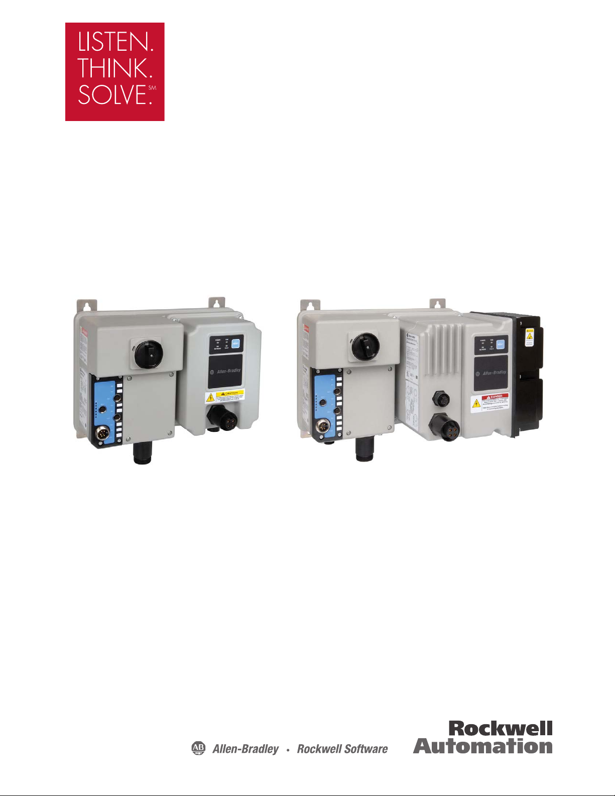
Description of Features Overload Protection
Class 15 Overload Curves
1
100
10000
0 100 200 300 400 500 600 700
Multiples for Full Load Current
Approximate Trip Time (sec)
Cold
Hot
Class 10 Ove rload Curv es
1
10
100
1000
10000
0 100 200 300 400 500 600 700
Multiples of Full Load Current
Approximate Trip Time (sec)
Cold
Hot
Class 20 Ove rload Curv es
1
100
10000
0 100 200 300 400 500 600 700
Multiples of Full Load Current
Approximate Trip Time (sec)
Cold
Hot
Class 10
Class 15
Class 20
%
%
of
%
The ArmorStart Distributed Motor Controller incorporates, as
standard, electronic motor overload protection. This overload
protection is accomplished electronically with an I
ArmorStart’s overload protection is programmable via the
communication network, providing the user with flexibility.
The Bulletin 280G/281G overload trip class can be selected for class
10, 15, 20 protection. Ambient insensitivity is inherent in the
electronic design of the overload.
Figure 1.1 Overload Trip Curves
Product Overview 1-3
2
t algorithm. The
Page 14
1-4 Product Overview
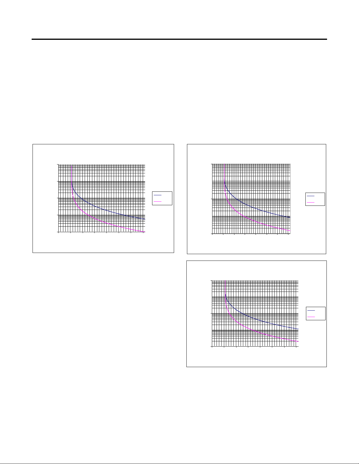
% of P132 (Motor NP Hertz) % of P132 (Motor NP Hertz)
% of P132 (Motor NP Hertz)
% of P133 (Motor OL Current)
% of P133 (Motor OL Current)
% of P133 (Motor OL Current)
The Bulletin 284G ArmorStart Distributed Motor Controller
incorporates, as standard, electronic motor overload protection. This
2
overload protection is accomplished electronically with an I
t
algorithm. The ArmorStart’s overload protection is programmable via
the communication network providing the user with flexibility.
Programming the Motor OL Current parameter provides class 10
overload protection for the Bulletin 284G Distributed Motor
Controller. Ambient insensitivity is inherent in the electronic design
of the overload.
Figure 1.2 Overload Trip Curves
Page 15
Product Overview 1-5
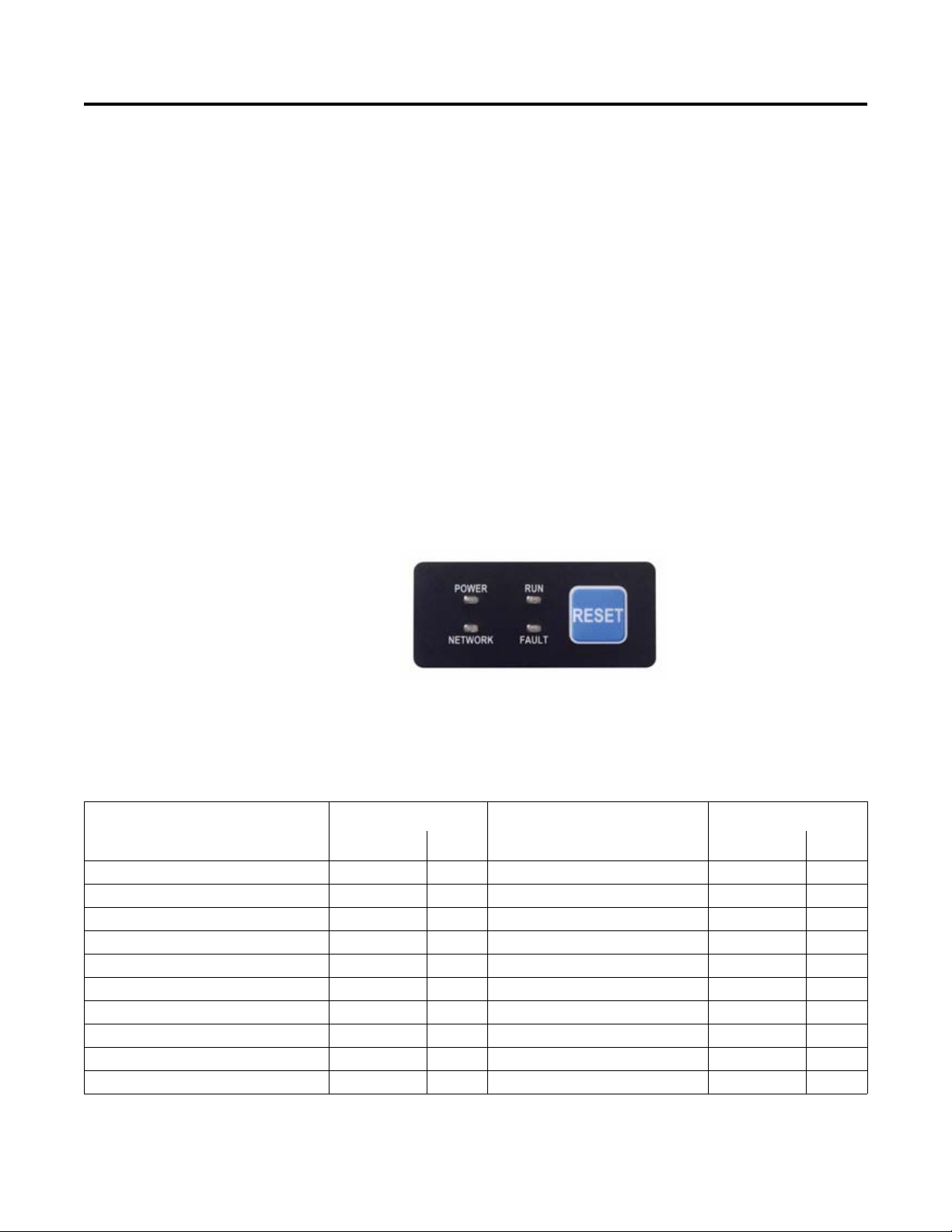
LED Status Indication
The LED Status Indication provides 4 status LEDs and a Reset
button. The LEDs provide status indication for the following:
•POWER LED
The LED is illuminated solid green when control power is present
and with the proper polarity
• RUN LED
This LED is illuminated solid green when a start command and
control power are present
•NETWORK LED
This bi-color (red/green) LED indicates the status of the
communication link
•FAULT LED
Indicates Controller Fault (Trip) condition
The “Reset Button” acts as a local trip reset.
Figure 1.3 Status Indication and Reset
Fault Diagnostics
Fault diagnostics capabilities built in the ArmorStart Distributed
Motor Controller help you pinpoint a problem for easy
troubleshooting and quick re-starting.
Fault Indication
• Short Circuit X X • Phase Imbalance X
• Overload X X • Miscellaneous Fault X
• Phase Loss X X • Brake Fuse Detection X
• Control Power Loss X X • Internal Comm. Fault X
• Control Power Fuse Detection X X • DC Bus Fault X
• I/O Fault X X • Ground Fault X
• Over Temperature X X • Overcurrent X
• DeviceNet™ Power Loss X X • Restart Retries X
• EEprom Fault X X • Stall X
• Hardware Fault X X • Phase Short X
Available on Bulletin:
Fault Indication
280G/281G 284G 280G/281G 284G
Available on Bulletin:
Page 16

1-6 Product Overview
Inputs
The inputs are single-keyed (2 inputs per connector), which are
sourced from DeviceNet power (24V DC), with LED status
indication.
Gland Plate Entrance
The ArmorStart product offers connectivity to the ArmorConnect™
power media. Receptacles are provided for connectivity to both threephase and control power media.
ArmorStart with DeviceNet Network Capabilities
The ArmorStart Distributed Motor Controller delivers advanced
capabilities to access parameter settings and provides fault
diagnostics, and remote start-stop control. DeviceNet is the
communication protocol, provided with the ArmorStart Bulletin
280G/281G or 284G Distributed Motor Controller.
DeviceLogix™
DeviceLogix is a stand-alone Boolean program that resides within the
ArmorStart Distributed Motor Controller. DeviceLogix is
programmed using Boolean math operations, such as, AND, OR,
NOT, Timers, Counters, and Latches. DeviceLogix can run as a standalone application, independent of the network. However, 24V DC
must be supplied at the DeviceNet connector to power the inputs.
Peer to Peer Communications (ZIP)
The zone control capabilities of ArmorStart Distributed Motor
Controllers is ideal for large horsepower (0.5…15 Hp) motored
conveyors. The ArmorStart Distributed Motor Controllers have builtin DeviceNet communications, DeviceLogix technology, and the
added Zone Interlocking Parameters (ZIP) which allow one
ArmorStart to receive data directly, from up to four other DeviceNet
nodes, without going through a network scanner. These direct
communications between conveyor zones are beneficial in a merge,
diverter, or accumulation conveyor application.
EMI Filter (Bulletin 284G only)
The EMI Filter is required if the Bulletin 284G ArmorStart
Distributed Motor Controller must be CE-compliant. A shielded
4-conductor patchcord or cordset no longer than 14 meters, must be
used to comply with the CE requirement.
Page 17

Product Overview 1-7
Dynamic Brake Resistor (Bulletin 284G only)
The IP67 Dynamic Brake Resistor plug and play design offers
simplicity in writing and installation. The factory installed option of
DB1 must be selected in order to have the quick disconnect
connectivity. The cable length of the IP67 Dynamic Brake Resistor is
available in two lengths, 0.5 meter and 1 meter. See Appendix G,
Accessories, for available IP67 Dynamic Brake Resistors.
Note: The IP67 Dynamic Brake Resistor is used only with the -DB1
factory-installed option.
Control Brake Contactor
An internal contactor is used to switch the electromechanical motor
brake On/Off. The motor brake is powered from the control voltage
circuit.
Page 18

1-8 Product Overview
Notes:
Page 19

Chapter 2
Installation and Wiring
Receiving It is the responsibility of the user to thoroughly inspect the equipment
before accepting the shipment from the freight company. Check the
item(s) received against the purchase order. If any items are damaged,
it is the responsibility of the user not to accept delivery until the
freight agent has noted the damage on the freight bill. Should any
concealed damage be found during unpacking, it is again the
responsibility of the user to notify the freight agent. The shipping
container must be left intact and the freight agent should be requested
to make a visual inspection of the equipment.
Unpacking Remove all packing material, wedges, or braces from within and
around the starter. Remove all packing material from device(s).
Inspecting After unpacking, check the nameplate catalog number(s) against the
purchase order.
Storing The controller should remain in its shipping container prior to
installation. If the equipment is not to be used for a period of time, it
must be stored according to the following instructions in order to
maintain warranty coverage.
• Store in a clean, dry location.
• Store within an ambient temperature range of –25…+85 °C
(–13…+185 °F).
• Store within a relative humidity range of 0…95%,
noncondensing.
• Do not store equipment where it could be exposed to a corrosive
atmosphere.
• Do not store equipment in a construction area.
Page 20
2-2 Installation and Wiring
ATTENTION
!
ATTENTION
!
ATTENTION
!
ATTENTION
!
ATTENTION
!
General Precautions In addition to the precautions listed throughout this manual, the
following statements, which are general to the system, must be read
and understood.
The controller contains ESD (electrostatic
discharge)-sensitive parts and assemblies. Static
control precautions are required when installing,
testing, servicing, or repairing the assembly.
Component damage may result if ESD control
procedures are not followed. If you are not familiar
with static control procedures, refer to Publication
8000-4.5.2, Guarding against Electrostatic
Discharge, or any other applicable ESD protection
handbooks.
An incorrectly applied or installed controller can
damage components or reduce product life. Wiring
or application errors, such as undersizing the motor,
incorrect or inadequate AC supply, or excessive
ambient temperatures, may result in malfunction of
the system.
Precautions for Bulletin 280G/281G
Applications
Only personnel familiar with the controller and
associated machinery should plan or implement the
installation, startup, and subsequent maintenance of
the system. Failure to do this may result in personal
injury and/or equipment damage.
To prevent electrical shock, open disconnect prior
to connecting and disconnecting cables. Risk of
shock - environment rating may not be maintained
with open receptacles.
Only qualified personnel familiar with adjustable
frequency AC drives and associated machinery
should plan or implement the installation, startup,
and subsequent maintenance of the system. Failure
to do this may result in personal injury and/or
equipment damage.
Page 21

Precautions for Bulletin 284G
ATTENTION
!
ATTENTION
!
Applications
Installation and Wiring 2-3
The drive contains high voltage capacitors which
take time to discharge after removal of mains
supply. Before working on drive, ensure isolation of
mains supply from line inputs (R, S, T [L1, L2, L3]).
Wait three minutes for capacitors to discharge to
safe voltage levels. Failure to do so may result in
personal injury or death. Darkened display LEDs
are not an indication that capacitors have discharged
to safe voltage levels. Risk of shock-environment
rating may not be maintained with open receptacles.
Only qualified personnel familiar with adjustable
frequency AC drives and associated machinery
should plan or implement the installation, startup,
and subsequent maintenance of the system. Failure
to do this may result in personal injury and/or
equipment damage.
Page 22
2-4 Installation and Wiring
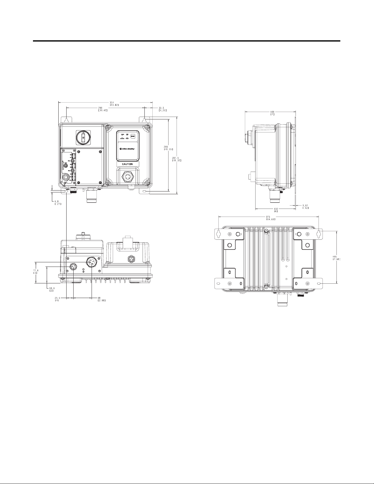
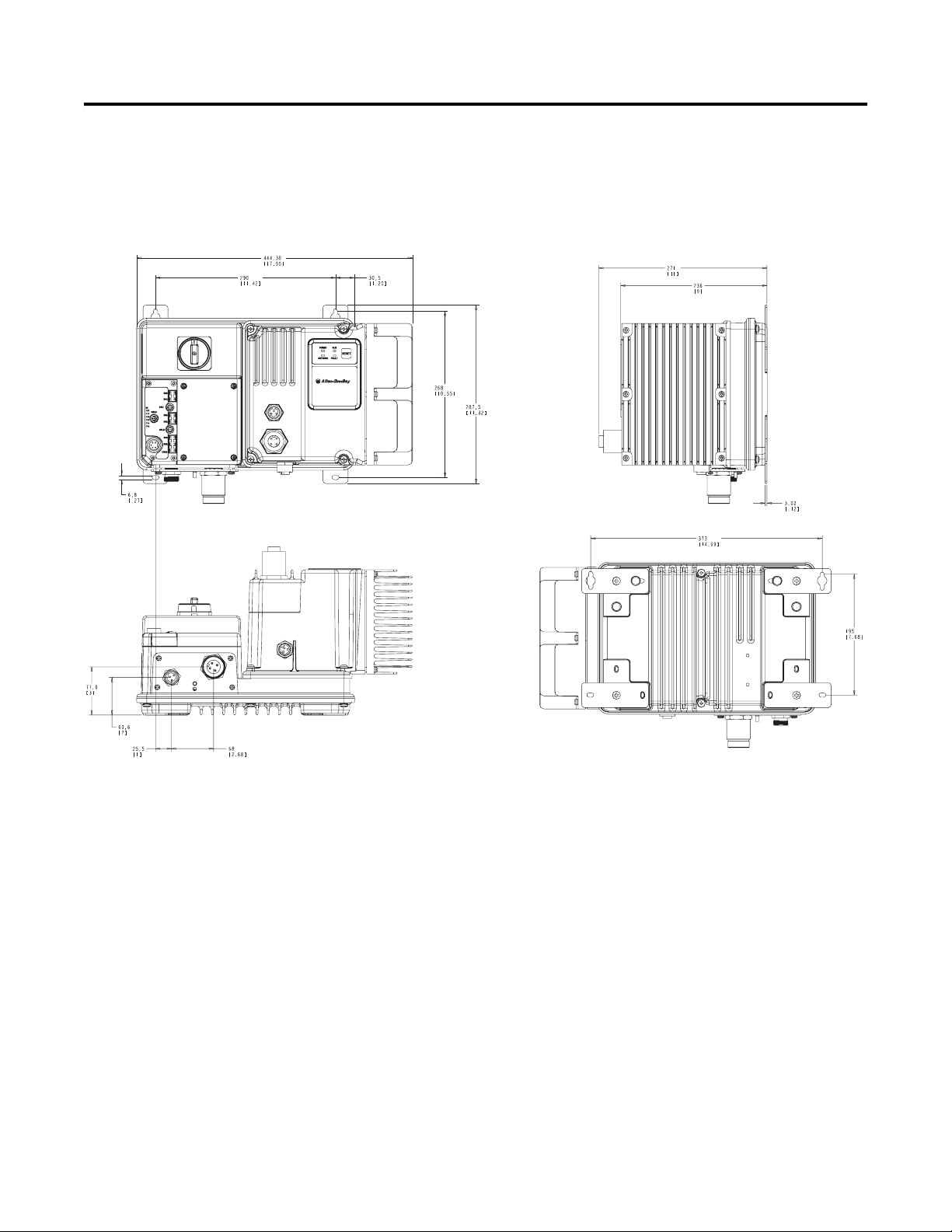
Dimensions for Bulletin 280G/281G Dimensions are shown in millimeters (inches). Dimensions are not
intended to be used for manufacturing purposes. All dimensions are
subject to change.
Figure 2.1 Dimensions for IP67/NEMA Type 4 with ArmorConnect
Connectivity
Page 23
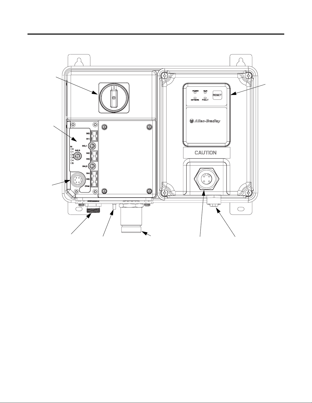
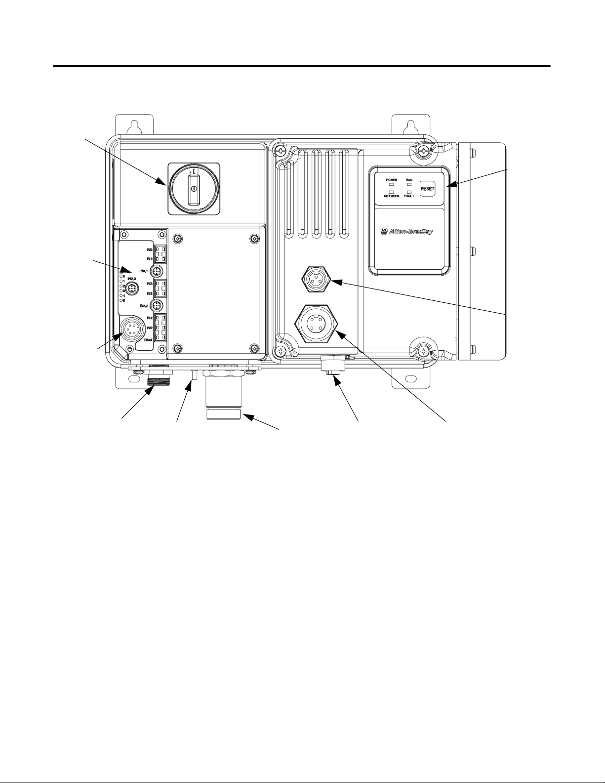
Installation and Wiring 2-5
Motor
Connection
DeviceNet
Connection
(Mini/M18)
Local Disconnect
6 Inputs
(Micro/M12)
Ground Terminal
Control Brake
Control Power
Receptacle
3-Phase Power
Receptacle
LED Status
Indication
Figure 2.2 Bulletin 280G/281G ArmorStart® with DeviceNet™
Communication Protocol
Page 24
2-6 Installation and Wiring
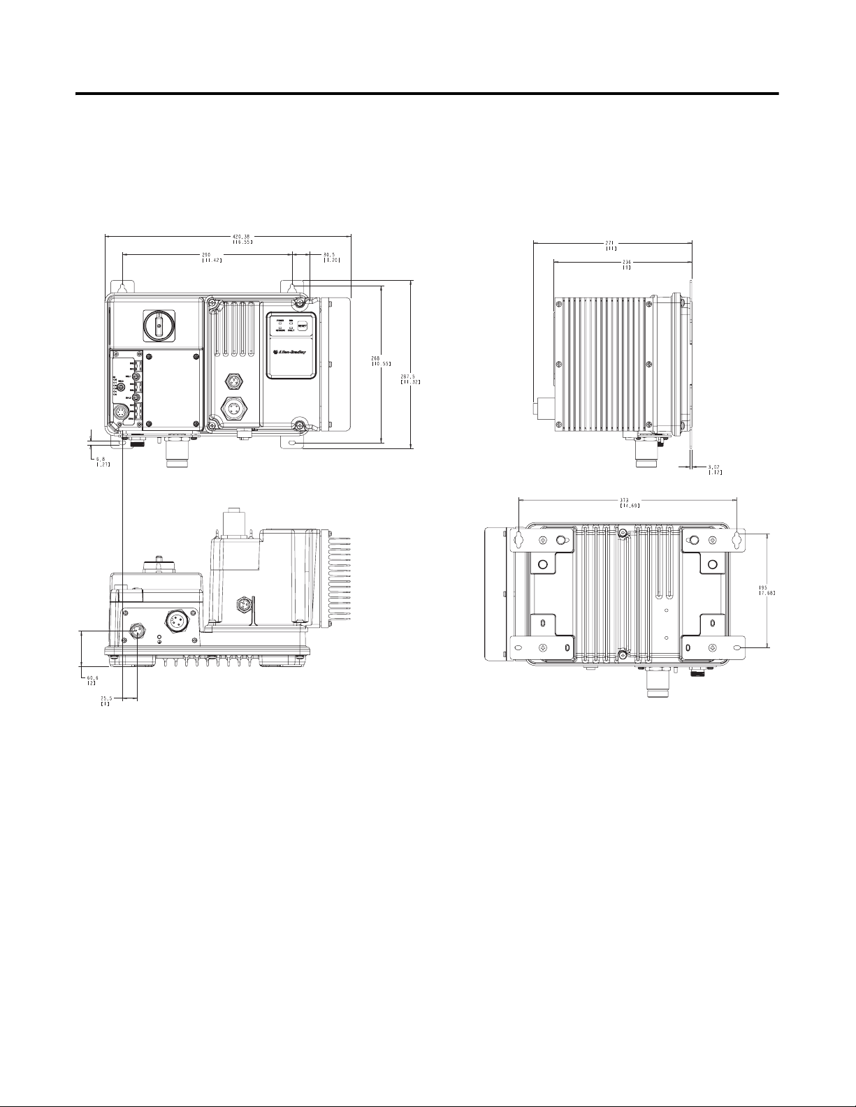
Dimensions for Bulletin 284G Dimensions are shown in millimeters (inches). Dimensions are not
intended to be used for manufacturing purposes. All dimensions are
subject to change.
Figure 2.3 Dimensions for 2 Hp (1.5 kW) and below @ 460V AC, IP67/NEMA
Type 4 with ArmorConnect connectivity
Page 25
Installation and Wiring 2-7
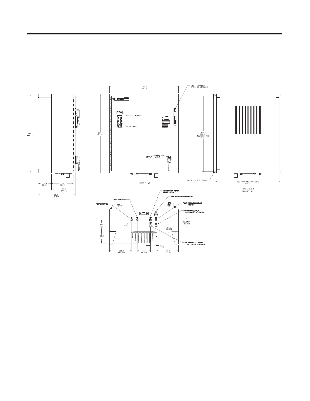
Dimensions for Bulletin 284G,
Continued
Dimensions are shown in millimeters (inches). Dimensions are not
intended to be used for manufacturing purposes. All dimensions are
subject to change.
Figure 2.4 Dimensions for 3 Hp (2.2 kW) and above @ 460V AC, IP67/NEMA
Type 4 with ArmorConnect connectivity
Page 26
2-8 Installation and Wiring
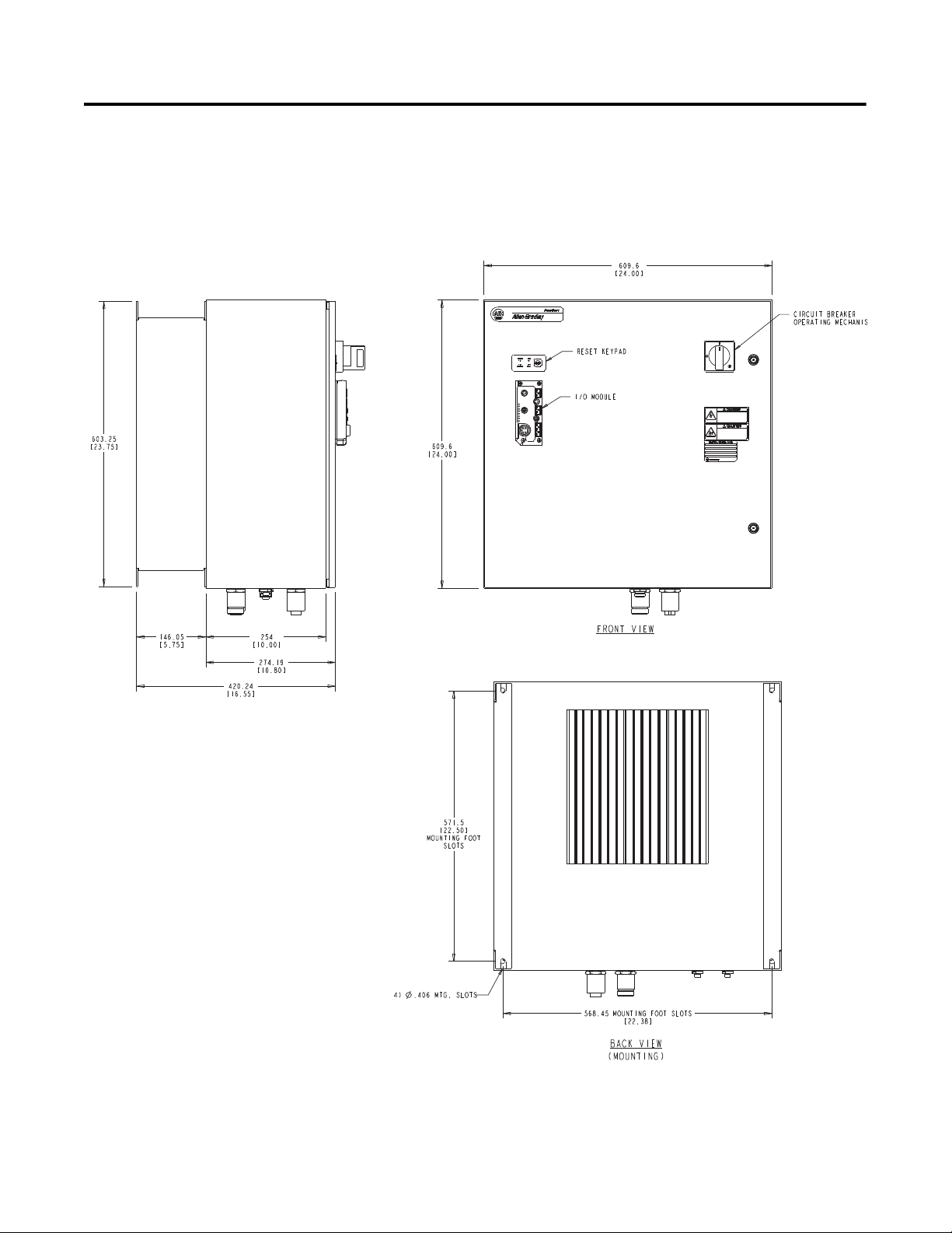
Dimensions for Bulletin 1000 Dimensions are shown in millimeters (inches). Dimensions are not
intended to be used for manufacturing purposes. All dimensions are
subject to change.
Figure 2.5 Dimensions for 7.5 Hp (5.5 kW) and 10 Hp (7.5 kW) @ 460V AC,
IP67/NEMA Type 4 with ArmorConnect Connectivity
Page 27
Installation and Wiring 2-9
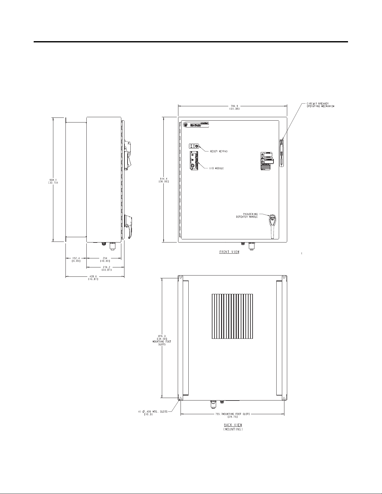
Dimensions for Bulletin 1000,
Continued
Dimensions are shown in millimeters (inches). Dimensions are not
intended to be used for manufacturing purposes. All dimensions are
subject to change.
Figure 2.6 Dimensions for 15 Hp (11 kW) @ 460V AC, IP67/NEMA Type 4 with
ArmorConnect Connectivity
Page 28
2-10 Installation and Wiring
LED Status
Indication
Motor
Connector
Dynamic
Brake Connector
Control Brake
Connector
Ground
Te r mi n a l
3-Phase
Receptacle
Control Power
Receptacle
DeviceNet
Connection
(Mini/M18)
Local Disconnect
6 Inputs
(Micro/M12)
Figure 2.7 Bulletin 284G ArmorStart
Page 29
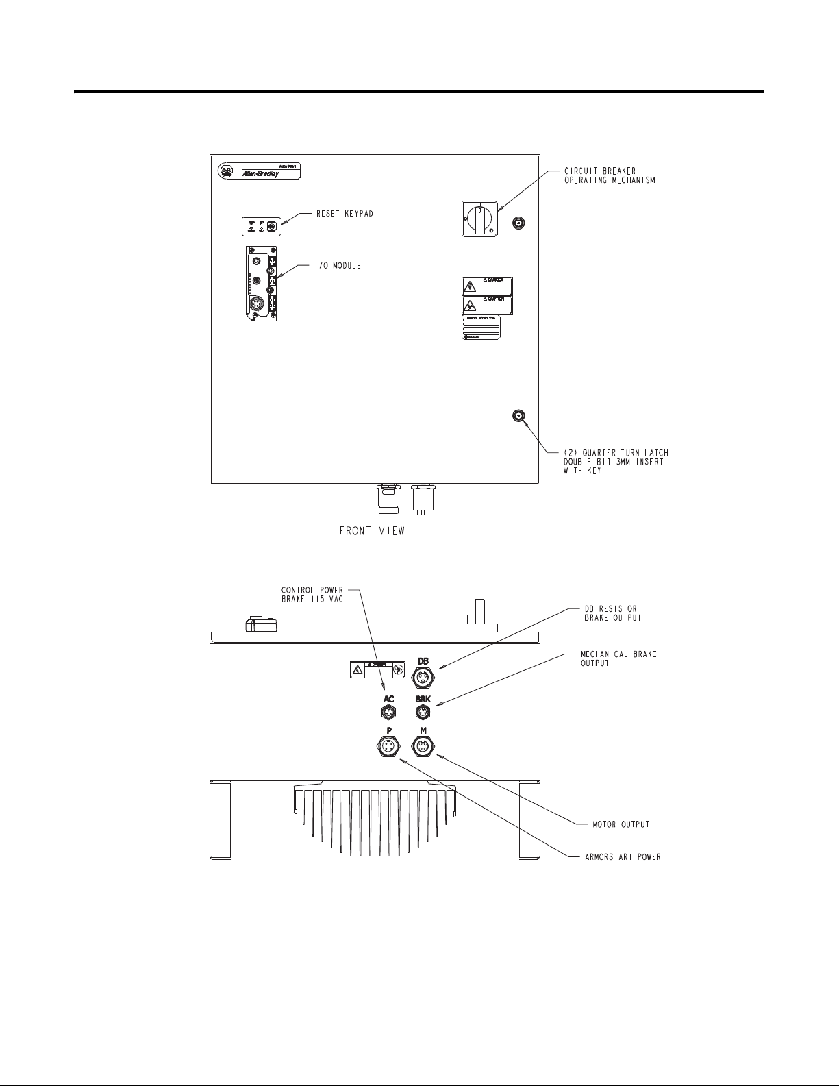
Figure 2.8 Bulletin 1000 ArmorStart
Installation and Wiring 2-11
Page 30
2-12 Installation and Wiring
Figure 2.9 Bulletin 1000 ArmorStart
Page 31

Wiring Power, Control, and Ground Wiring
Table 2.1 provides the power, control, safety inputs, and ground wire
capacities, and the tightening torque requirements. The power,
control, ground, and safety monitor terminals will accept a maximum
of two wires per terminal.
Table 2.1 Power, Control, Safety Input, Ground Wire Size, and Torque
Specifications
Terminals Wire Size Torque Wire Strip Length
Installation and Wiring 2-13
Power
and
Ground
Control and Safety
Inputs
Primary/Secondary
Terminal:
1.5…4.0 mm
(#16 …#10 AWG)
1.0 mm
(#18…#10 AWG)
2
…4.0 mm2
2
Primary Terminal:
Secondary Terminal:
10.8 lb.-in.
(1.2 N•m)
4.5 lb.-in
(0.5 N•m)
6.2 lb.-in
(0.7 N•m)
0.35 in. (9 mm)
0.35 in. (9 mm)
Page 32
2-14 Installation and Wiring
Terminal Designations for Bulletins
280G, 281G, and 284G
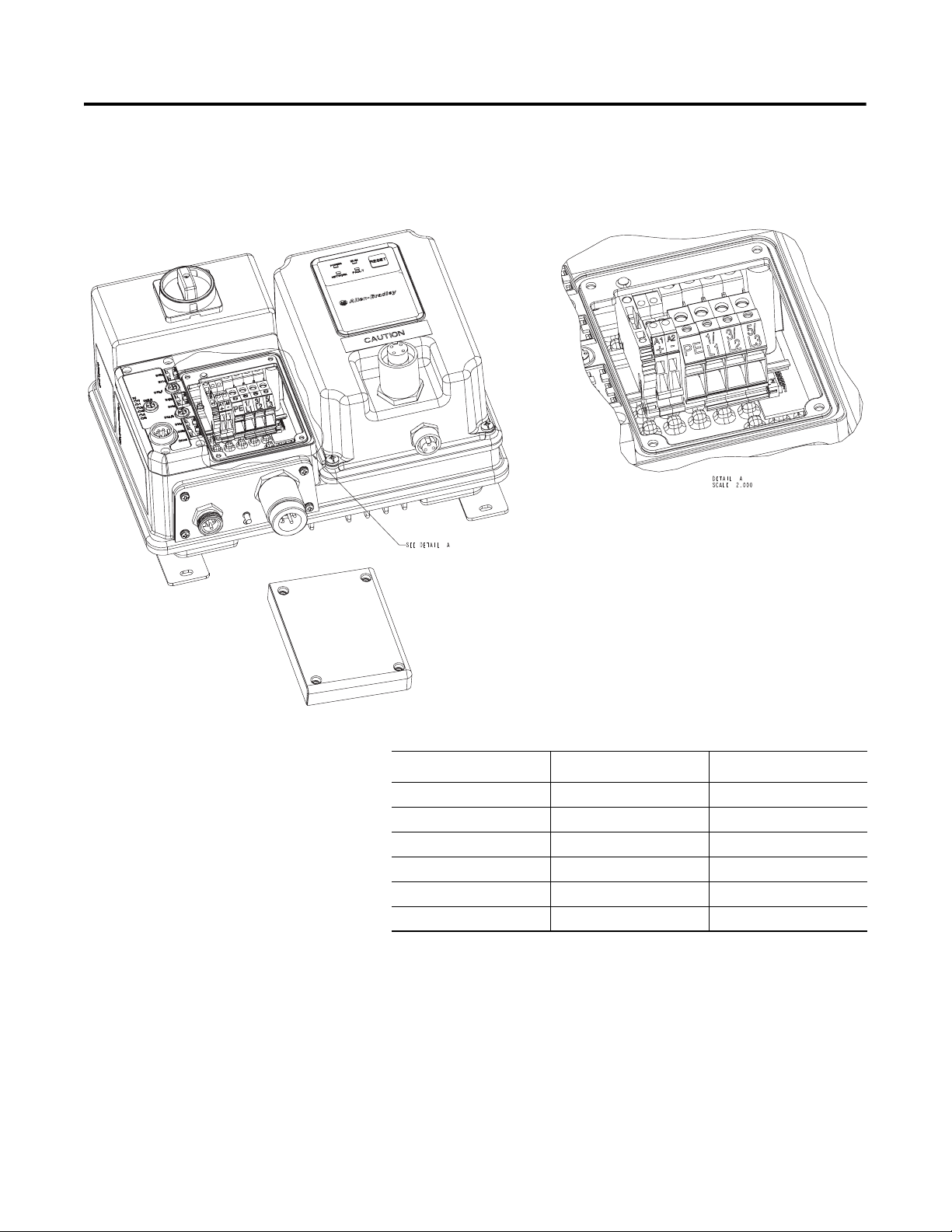
As shown in the next figure, the ArmorStart Distributed Motor Controller
contains terminals for power, control, and ground wiring. Access can be
gained by removing the terminal access cover plate.
Figure 2.10 ArmorStart Power, Control and Terminals
Table 2.2 Power, Control, and Ground Terminal Designations
Terminal Designations No. of Poles Description
A1 (+) 2 Control Power Input
A2 (-) 2 Control Power Common
PE 2 Ground
1/L1 2 Line Power Phase A
3/L3 2 Line Power Phase B
5/L5 2 Line Power Phase C
Page 33

Installation and Wiring 2-15
Dimensions for Bulletin 280G
Safety Product
Dimensions are shown in millimeters (inches). Dimensions are not
intended to be used for manufacturing purposes. All dimensions are
subject to change.
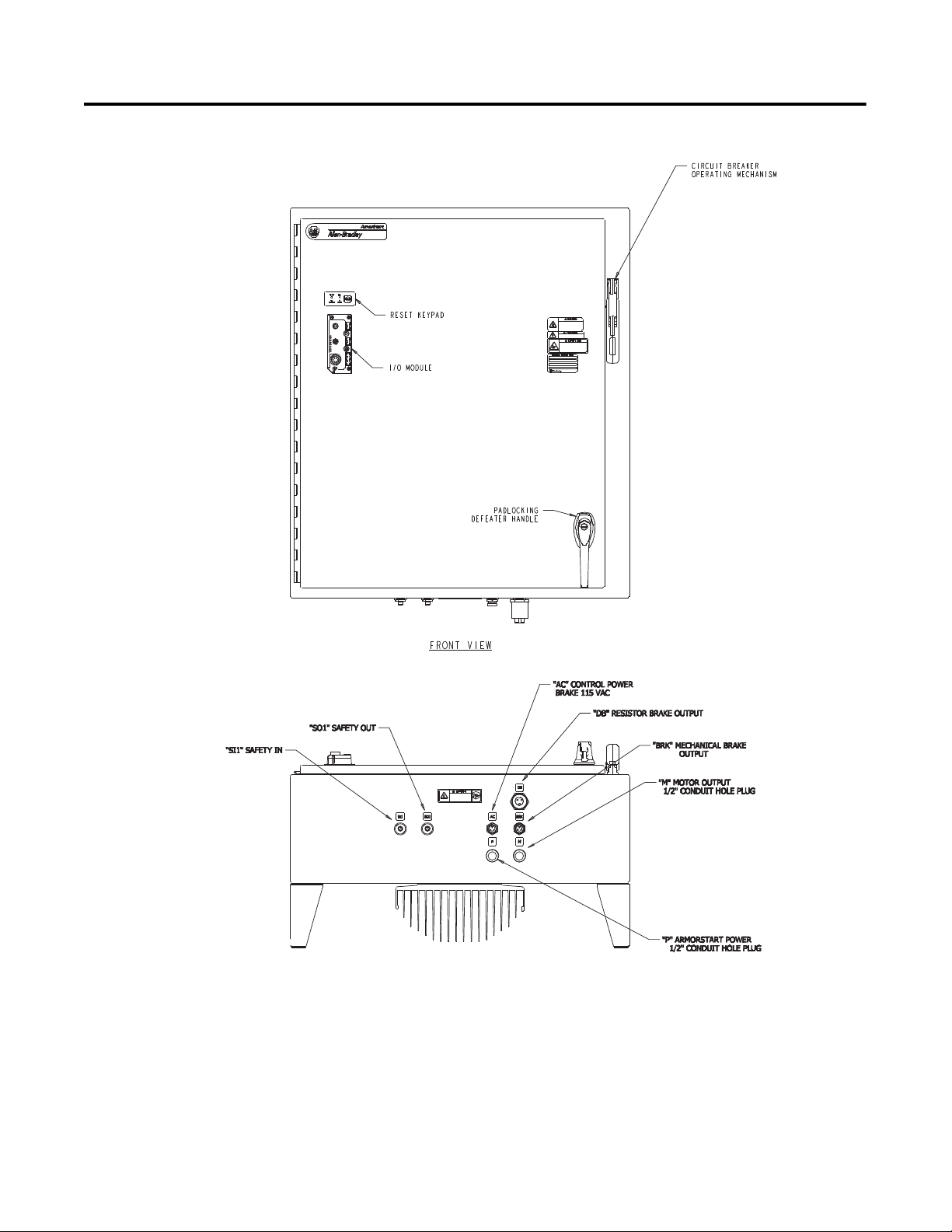
Figure 2.11 Dimensions for Bulletin 280G Safety Product
Page 34

2-16 Installation and Wiring
Dimensions for Bulletin 281G
Safety Product
Dimensions are shown in millimeters (inches). Dimensions are not
intended to be used for manufacturing purposes. All dimensions are
subject to change.
Figure 2.12 Dimensions for Bulletin 281G Safety Product
Page 35

Installation and Wiring 2-17
Dimensions for Bulletin 284G
Safety Product
Dimensions are shown in millimeters (inches). Dimensions are not
intended to be used for manufacturing purposes. All dimensions are
subject to change.
Figure 2.13 Dimensions for 2 Hp (1.5 kW) and below @ 460V AC, IP67/NEMA
Type 4 with ArmorConnect connectivity
Page 36

2-18 Installation and Wiring
Dimensions for Bulletin 284G
Safety Product, Continued
Dimensions are shown in millimeters (inches). Dimensions are not
intended to be used for manufacturing purposes. All dimensions are
subject to change.
Figure 2.14 Dimensions for 3 Hp (2.2 kW) and 5 Hp (3.0 kW) and below @
460V AC, IP67/NEMA Type 4 with ArmorConnect connectivity
Page 37

Installation and Wiring 2-19
Dimensions for Bulletin 1000
Safety Product
Dimensions are shown in millimeters (inches). Dimensions are not
intended to be used for manufacturing purposes. All dimensions are
subject to change.
Figure 2.15 Dimensions for 7.5 Hp (5.5 kW) and 10 Hp (7.5 kW) @ 460V AC,
IP67/NEMA Type 4 with ArmorConnect Connectivity
Page 38
2-20 Installation and Wiring
Dimensions for Bulletin 1000
Safety Product, Continued
Dimensions are shown in millimeters (inches). Dimensions are not
intended to be used for manufacturing purposes. All dimensions are
subject to change.
Figure 2.16 Dimensions for 15 Hp @ 460V AC, IP67/NEMA Type 4 with
ArmorConnect Connectivity
Page 39

Figure 2.17 Bulletin 280G Safety ArmorStart
Motor
Connection
DeviceNet
Connection
(Mini/M18)
Local Disconnect
6 Inputs
(Micro/M12)
A1/A2
Control Brake
Control Power
Receptacle
3-Phase Power
Receptacle
LED Status
Indication
SM
Installation and Wiring 2-21
Page 40

2-22 Installation and Wiring
Motor
Connection
DeviceNet
Connection
(Mini/M18)
Local Disconnect
6 Inputs
(Micro/M12)
3-Phase Power
Receptacle
LED Status
Indication
A1/A2
Control Power
SM
Control Brake
Figure 2.18 Bulletin 281G Safety ArmorStart
Page 41

Figure 2.19 Bulletin 284G Safety ArmorStart
Motor
Connection
DeviceNet
Connection
(Mini/M18)
Local Disconnect
6 Inputs
(Micro/M12)
Dynamic Brake
3-Phase Power
Receptacle
LED Status
Indication
A1/A2
Control Power
SM
Control Brake
Installation and Wiring 2-23
Page 42

2-24 Installation and Wiring
Figure 2.20 Bulletin 1000 Safety ArmorStart
Page 43

Figure 2.21 Bulletin 1000 ArmorStart
Installation and Wiring 2-25
Page 44

2-26 Installation and Wiring
Safety Terminal Designations As shown in the next figure, the ArmorStart Distributed Motor Controller
contains terminals for power, safety I/O inputs, control, and ground wiring.
Access can be gained by removing the terminal access cover plate.
Figure 2.22 Bulletin 280G ArmorStart Safety Power, Control and Terminals
Table 2.3 Power, Control, Safety Monitor, and Ground Terminal Designations
Terminal Designations No. of Poles Description
SM1 2 Safety I/O Input
SM2 2 Safety I/O Input
A1 (+) 2 Control Power Input
A2 (-) 2 Control Power Common
PE 2 Ground
1/L1 2 Line Power Phase A
3/L3 2 Line Power Phase B
5/L5 2 Line Power Phase C
Page 45

Installation and Wiring 2-27
Safety Terminal Designations,
Continued
As shown in the next figure, the ArmorStart Distributed Motor Controller
contains terminals for power, safety I/O inputs, control, and ground wiring.
Access can be gained by removing the terminal access cover plate.
Figure 2.23 Bulletin 281G ArmorStart Safety Power, Control and Terminals
Table 2.4 Power, Control, Safety Monitor, and Ground Terminal Designations
Terminal Designations No. of Poles Description
SM1 2 Safety I/O Input
SM2 2 Safety I/O Input
A1 (+) 2 Control Power Input
A2 (-) 2 Control Power Common
PE 2 Ground
1/L1 2 Line Power Phase A
3/L3 2 Line Power Phase B
5/L5 2 Line Power Phase C
Page 46

2-28 Installation and Wiring
Safety Terminal Designations,
Continued
As shown in the next figure, the ArmorStart Distributed Motor Controller
contains terminals for power, safety I/O inputs, control, and ground wiring.
Access can be gained by removing the terminal access cover plate.
Figure 2.24 ArmorStart Safety 2 Hp Power, Control and Terminals
Table 2.5 Power, Control, Safety Monitor, and Ground Terminal Designations
Terminal Designations No. of Poles Description
SM1 2 Safety I/O Input
SM2 2 Safety I/O Input
A1 (+) 2 Control Power Input
A2 (-) 2 Control Power Common
PE 2 Ground
1/L1 2 Line Power Phase A
3/L3 2 Line Power Phase B
5/L5 2 Line Power Phase C
Page 47

ArmorConnect Power Media Description
Encl
The ArmorConnect power media offers both three-phase and control
power cable system of cord sets, patch cords, receptacles, tees,
reducers and accessories to be utilized with the ArmorStart
Distributed Motor Controller. These cable system components allow
quick connection of ArmorStart Distributed Motor Controllers, there
by reducing installation time. They provide for repeatable, reliable
connection of the three-phase and control power to the ArmorStart
Distributed Motor Controller and motor by providing a plug-and-play
environment that also avoids system mis-wiring. When specifying
power media for use with the ArmorStart Distributed Motor
Controllers (Bulletin 280G/281G and 284G) use only the Bulletin
280 ArmorConnect power media.
Figure 2.25 Three-Phase Power System Overview
osure
Bulletin 1492FB
Branch Circuit
Protective Device
Bulletin 1606
Power Supply
1606-XLSDNET4
DeviceNet
Power Supply
Installation and Wiring 2-29
PLC
Bulletin 280/281
ArmorStart
RESET
Bulletin 280/281
ArmorStart
RESET
➊ Three-Phase Power Trunk- PatchCord cable with integral female or male connector on each end
Example Part Number: 280-PWR35A-M*
➋ Three-Phase Drop Cable- PatchCord cable with integral female or male connector on each end
Example Part Number: 280-PWR35A-M*
➌ Three-Phase Power Tee and Reducer -
Tee connects to a single drop line to trunk with quick change connectors – Part Number: 280-T35
Reducing Tee connects to a single drop line (Mini) to trunk (Quick change) connector – Part Number: 280-RT35
➍ Three-Phase Power Receptacles -
Female receptacles are a panel mount connector with flying leads – Part Number: 280-M35F-M1
Bulletin 284
ArmorStart
Page 48

2-30 Installation and Wiring
RESET
Bulletin 280/281
ArmorStart
Bulletin 284
ArmorStart
RESET
Bulletin 280/281
ArmorStart
PLC
Bulletin 1492FB
Branch Circuit
Protective Device
Enclosure
Bulletin 1606
Power Supply
1606-XLSDNET4
DeviceNet
Power Supply
Figure 2.26 Control Power Media System Overview
➏ Control Power Media Patchcords - PatchCord cable with integral female or male connector on each end
Example Part Number: 889N-F3AFNU-*F
➐ Control Power Tees - The Control Power tee (Part Number: 898N-33PB-N4KF) is used with a patchcord to connect to the ArmorStart Distributed Motor
Controller.
➑ Control Power Receptacles - Female receptacles are a panel mount connector with flying leads –
Part Number: 888N-D3AF1-*F
Page 49

Installation and Wiring 2-31
Control Power
Receptacle
Ground
Term in al
Three-Phase
Power
Receptacle
Term in al
Designations
Description Color Code
A1 (+) Control Power Input Black
A2 (-) Control Power Common White
PE Ground Green/Yellow
1/L1 Line Power - Phase A Black
3/L2 Line Power - Phase B White
5/L3 Line Power - Phase C Red
ArmorStart with ArmorConnect Connectivity
Terminal Designations
ArmorConnect Cable Ratings
The ArmorConnect power media cables are rated per UL Type TC
600V 90 °C Dry 75 °C Wet, Exposed Run (ER) or MTW 600V 90 °C
or STOOW 105 °C 600V - CSA STOOW 600V FT2.
Page 50

2-32 Installation and Wiring
Ground
Termi na l
Three-Phase
Power
Recepale
120V AC
Aux. Powr
for
Conto Brake
Safety Monitor
Input from
1732DS Safey
I/O Module Inpt
A1/A2 -24V DC
Control Power rm
1732DS Safety
I/O Module Outu
Term in al
Designations
Description Color Code
SM1 Safety Monitor Input Brown
SM2 Safety Monitor Input White
A1 (+) Control Power Input Brown
A2 (-) Control Power Common Blue
PE Ground Green/Yellow
1/L1 Line Power - Phase A Black
3/L2 Line Power - Phase B White
5/L3 Line Power - Phase C Red
ArmorStart Safety with ArmorConnect Connectivity
Terminal Designations
ArmorConnect Cable Ratings
The ArmorConnect power media cables are rated per UL Type TC
600V 90 °C Dry 75 °C Wet, Exposed Run (ER) or MTW 600V 90 °C
or STOOW 105 °C 600V - CSA STOOW 600V FT2.
Page 51

Installation and Wiring 2-33
Branch Circuit Protection Requirements for ArmorConnect
Three-Phase Power Media
When using ArmorConnect three-phase power media, fuses can be
used for the motor branch circuit protective device, for the group
motor installations. The following fuse types are recommended: Class
CC, T, or J type fuses. A 100 A circuit breaker (Allen-Bradley140
H-Frame) can be used for the motor branch protective device, for the
group motor installations when using only the following
ArmorConnect Power Media components: 280-M35M-M1,
280-M35F-M1, 280-T35, and 280-PWRM35*-M*.
Maximum Ratings
Voltage (V) 480Y/277
Sym. Amps RMS 65 kA
Fuse 100 A
Circuit Breaker 100 A
Group Motor Installations for USA
and Canada Markets
Wiring and Workmanship
Guidelines
The ArmorStart Distributed Motor Controllers are listed for use with
each other in group installations per NFPA 79, Electrical Standard for
Industrial Machinery. When applied according to the group motor
installation requirements, two or more motors, of any rating or
controller type, are permitted on a single branch circuit. Group Motor
Installation has been successfully used for many years in the USA and
Canada.
Note: For additional information regarding group motor
installations with the ArmorStart Distributed Motor
Controller, see Appendix D.
In addition to conduit and seal-tite raceway, it is acceptable to utilize
cable that is dual rated Tray Cable, Type TC-ER and Cord, STOOW,
for power and control wiring on ArmorStart installations. In the USA
and Canada installations, the following guidance is outlined by the
NEC and NFPA 79.
Page 52

2-34 Installation and Wiring
In industrial establishments where the conditions of maintenance and
supervision ensure that only qualified persons service the installation,
and where the exposed cable is continuously supported and protected
against physical damage using mechanical protection, such as struts,
angles, or channels, Type TC tray cable that complies with the crush
and impact requirements of Type MC (Metal Clad) cable and is
identified for such use with the marking Type TC-ER (Exposed
Run)* shall be permitted between a cable tray and the utilization
equipment or device as open wiring. The cable shall be secured at
intervals not exceeding 1.8 m (6 ft) and installed in a “good workmanlike” manner. Equipment grounding for the utilization equipment
shall be provided by an equipment grounding conductor within the
cable.
*Historically cable meeting these crush and impact requirements
were designated and marked “Open Wiring”. Cable so marked is
equivalent to the present Type TC-ER and can be used.
While the ArmorStart is intended for installation in factory floor
environments of industrial establishments, the following must be
taken into consideration when locating the ArmorStart in the
application: Cables, including those for control voltage including
24V DC and communications, are not to be exposed to an operator or
building traffic on a continuous basis. Location of the ArmorStart to
minimize exposure to continual traffic is recommended. If location to
minimize traffic flow is unavoidable, other barriers to minimize
inadvertent exposure to the cabling should be considered. Routing
cables should be done in such a manner to minimize inadvertent
exposure and/or damage.
Additionally, if conduit or other raceways are not used, it is
recommended that strain relief fittings be utilized when installing the
cables for the control and power wiring through the conduit openings.
The working space around the ArmorStart may be minimized as the
ArmorStart does not require examination, adjustment, servicing or
maintenance while energized. In lieu of this service, the ArmorStart is
meant to be unplugged and replaced after proper lockout/tag-out
procedures have been employed.
DeviceNet Network Installation The ArmorStart Distributed Motor Controller contains the equivalent
of 30 in. (0.76 m) of DeviceNet drop cable's electrical characteristics
and therefore 30 in. of drop cable must be included in the DeviceNet
drop cable budget for each ArmorStart in addition to actual drop cable
required for the installation.
Other DeviceNet System Design Considerations
The separation of the control power and DeviceNet power is
recommended as a good design practice. This minimizes the load on
the DeviceNet supply, and prevents transients which may be present
on the control power system from influencing the communication
controls.
Page 53

Installation and Wiring 2-35
Electromagnetic Compatibility
(EMC)
The following guidelines are provided for EMC installation
compliance.
General Notes (Bulletin 284G only)
• The motor Cable should be kept as short as possible in order to
avoid electromagnetic emission as well as capacitive currents
• Conformity of the drive with CE EMC requirements does not
guarantee an entire machine installation complies with CE EMC
requirements. Many factors can influence total machine/
installation compliance.
• Using an EMI filter with any drive rating, may result in relatively
high ground leakage currents. Therefore, the filter must only be
used in installations and solidly grounded (bonded) to the
building power distribution ground. Grounding must not rely on
flexible cables and should not include any form of plug or socket
that would permit inadvertent disconnection. Some local codes
may require redundant ground connections. The integrity of all
connections should be periodically checked.
Grounding
Connect a grounding conductor to the terminal provided as standard
on each ArmorStart Distributed Motor Controller. Refer to Table 2.2
for grounding provision location. There is also an externally available
ground terminal. Refer to Figure 2.2 and Figure 2.7.
Wiring
Wire in an industrial control application can be divided into three
groups: power, control, and signal. The following recommendations
for physical separation between these groups is provided to reduce the
coupling effect.
• Minimum spacing between different wire groups in the same tray
should be 6 in. (16 cm).
• Wire runs outside an enclosure should be run in conduit or have
shielding/armor with equivalent attenuation.
• Different wire groups should be run in separate conduits.
• Minimum spacing between conduits containing different wire
groups should be 3 in. (8 cm).
Page 54

2-36 Installation and Wiring
Notes:
Page 55

Chapter 3
Bulletin 280G/281G Programmable
Parameters
Introduction This chapter describes each programmable parameter and its
function.
Parameter Programming
Each Distributed Motor Controller type will have a common set of
parameters followed by a set of parameters that pertain to the
individual starter type.
Refer to Chapter 5, DeviceNet™ Commissioning for instructions in
using RSNetWorx™ for DeviceNet to modify parameter settings.
Important: Resetting the Factory Default Values Parameter 47,
Set to Defaults, allows the installer to reset all parameters
to the factory default values. It also resets the MAC ID to
its factory default after DeviceNet Power is cycled if
switches are set >63.
Important: Parameter setting changes downloaded to the
ArmorStart™ take effect immediately, even during a
“running” status.
Important: Parameter setting changes made in a configuration tool
such as RSNetWorx for DeviceNet do not take effect in
the ArmorStart until the installer applies or downloads
the new settings to the device.
Page 56

3-2 Bulletin 280G/281G Programmable Parameters
Parameter Group Listing The Bulletin 280G/281G ArmorStart contains eight parameter
groups. The parameters shown in the DeviceLogix, DeviceNet,
Starter Protection, User I/O, Misc. Parameter, ZIP Parameters, Starter
Display and Starter Setup, are discussed in this chapter.
Table 3.1 Parameter Group Listing
DeviceLogix DeviceNet
1 Hdw Inputs 10 Autobaud Enable 22 Breaker Type 30 Off-to-On Delay 45 Keypad Mode 67 AutoRun Zip 101 Phase A Current 106 FLA Setting
2 Network Inputs 11 Consumed IO Assy 23 PrFltResetMode 31 On-to-Off Delay 46 Keypad Disable 68 Zone Produced EPR 102 Phase B Current 107 Overload Class
3 Network Outputs 12 Produced IO Assy 24 Pr Fault Enable 32 In Sink/Source 47 Set To Defaults 69 Zone Produced PIT 103 Phase C Current 108 OL Reset Level
4 Trip S tat us 13 Prod Assy Word 0 25 Pr Fault Reset 56 Base Enclosure 70 Zone #1 MacId 104 Average Current
5 Starter Status 14 Prod Assy Word 1 26 StrtrDN FltState 57 Base Option 71 Zone #2 MacId 105% Therm Utilized
6 DNet Status 15 Prod Assy Word 2 27 StrtrDN FltValue 58 Wiring Option 72 Zone #3 MacId
7 Starter Command 16 Prod Assy Word 3 28 StrtrDN IdlState 59 Starter Enclosure 73 Zone #4 MacId
8 Network Override 17 Consumed IO Size 29 StrtrDN IdlValue 60 Starter Options 74 Zone #1 Health
9 Comm Override 18 Produced IO Size 61 Last PR F
19 Starter COS Mask 62 W
20 Net Out COS Mask 77 Zone #4 Health
21 DNet Voltage 78 Zone #1 Mask
Starter
Protection
ault 75 Zone #2 Health
arning Status 76 Zone #3 Health
User I/O Misc. ZIP Parameters Starter Display Starter Setup
79 Zone #2 Mask
80 Zone #3 Mask
81 Zone #4 Mask
82 Zone #1 Offset
83 Zone #2 Offset
84 Zone #3 Offset
85 Zone #4 Offset
86 Zone #1 EPR
87 Zone #2 EPR
88 Zone #3 EPR
89 Zone #4 EPR
90 Zone #1 Control
91 Zone #2 Control
92 Zone #3 Control
93 Zone #4 Control
94 Zone #1 Key
95 Zone #2 Key
96 Zone #3 Key
97 Zone #4 Key
98 Device Value Key
99 Zone Ctrl Enable
DeviceLogix™ Group
Hdw Inputs
This parameter provides status of
hardware inputs
Parameter Number 1
Access Rule GET
Data Type WORD
Group DeviceLogix
Units —
Minimum Value 0
Maximum Value 15
Default Value 0
Page 57

Bulletin 280G/281G Programmable Parameters 3-3
Bit
543210
————— XInput 0
———— X —Input 1
— — — X — — Input 2
—— X ———Input 3
— X ————Input 4
X —————Input 5
Network Inputs
This parameter provides status of
network inputs
1514131211109876543210
——————————————— X Net Input 0
—————————————— X — Net Input 1
————————————— X —— Net input 2
———————————— X ——— Net Input 3
——————————— X ———— Net Input 4
—————————— X ————— Net Input 5
————————— X —————— Net Input 6
———————— X ——————— Net Input 7
——————— X ———————— Net Input 8
—————— X ————————— Net Input 9
————— X —————————— Net Input 10
———— X ——————————— Net Input 11
——— X ———————————— Net Input 12
—— X ————————————— Net Input 13
— X —————————————— Net Input 14
X ——————————————— Net Input 15
Parameter Number 2
Access Rule GET
Data Type WORD
Group DeviceLogix
Units —
Minimum Value 0
Maximum Value 65535
Default Value 0
Bit
Function
Function
Network Outputs
This parameter provides status of
network outputs
Parameter Number 3
Access Rule GET
Data Type WORD
Group DeviceLogix
Units —
Minimum Value 0
Maximum Value 32767
Default Value 0
Page 58

3-4 Bulletin 280G/281G Programmable Parameters
Bit
Function
14131211109876543210
—————————————— X Net Output 0
————————————— X — Net Output 1
———————————— X —— Net Output 2
——————————— X ——— Net Output 3
—————————— X ———— Net Output 4
————————— X ————— Net Output 5
———————— X —————— Net Output 6
——————— X ——————— Net Output 7
—————— X ———————— Net Output 8
————— X ————————— Net Output 9
———— X —————————— Net Output 10
——— X ——————————— Net Output 11
—— X ———————————— Net Output 12
— X ————————————— Net Output 13
X —————————————— Net Output 14
Trip Status
Parameter Number 4
Access Rule GET
This parameter provides trip
identification
Data Type WORD
Group DeviceLogix Setup
Units —
Minimum Value 0
Maximum Value 16383
Default Value 0
Bit
Function
131211109876543210
————————————— X Short Circuit
———————————— X — Overload
——————————— X —— Phase Loss
—————————— X ——— Reserved
————————— X ———— Reserved
———————— X ————— Control Power
——————— X —————— I/O Fault
—————— X ——————— Over Temperature
————— X ———————— Phase Imbalance
———— X ————————— Dnet Power Loss
——— X —————————— Reserved
—— X ——————————— Reserved
— X ———————————— EEprom
X ————————————— HW Fault
Page 59

Bulletin 280G/281G Programmable Parameters 3-5
Starter Status
This parameter provides the
status of the starter
131211109876543210
————————————— X Tripped
———————————— X — Warning
——————————— X —— Running Fwd
—————————— X ——— Running Rev
————————— X ———— Ready
———————— X ————— Net Ctl Status
——————— X —————— Reserved
—————— X ——————— At Reference
————— X ———————— Reserved
———— X ————————— Reserved
——— X —————————— Reserved
—— X ——————————— Keypad Hand
— X ———————————— HOA Status
X ————————————— 140M On
Parameter Number 5
Access Rule GET
Data Type WORD
Group DeviceLogix
Units —
Minimum Value 0
Maximum Value 16383
Default Value 0
Bit
Function
DNet Status
This parameter provides status of
the DeviceNet connection
Parameter Number 6
Access Rule GET
Data Type WORD
Group DeviceLogix
Units —
Minimum Value 0
Maximum Value 32, 767
Default Value 0
Page 60

3-6 Bulletin 280G/281G Programmable Parameters
Bit
1514131211109876543210
——————————————— X Explicit Connection
—————————————— X — I/O Connection
————————————— X —— Explicit Fault
———————————— X ——— I/O Fault
——————————— X ———— I/O Idle
———————— X X X ————— Reserved
——————— X ———————— ZIP 1 Cnxn
—————— X ————————— ZIP 1 Flt
————— X —————————— ZIP 2 Cnxn
———— X ——————————— ZIP 2 Flt
——— X ———————————— ZIP 3 Cnxn
—— X ————————————— ZIP 3 Flt
— X —————————————— ZIP 4 Cnxn
X ——————————————— ZIP 4 Flt
Starter Command
The parameter provides the
status of the starter command.
Parameter Number 7
Access Rule GET
Data Type WORD
Group DeviceLogix
Units —
Minimum Value 0
Maximum Value 255
Default Value 0
Function:
Bit
76543210
——————— X Run Fwd
—————— X — Run Rev
————— X —— Fault Reset
———— X ——— Reserved
——— X ———— Reserved
—— X ————— Reserved
— X —————— Reserved
X ——————— Reserved
Network Override
This parameter allows for the
local logic to override a Network
fault
0 = Disable
1 = Enable
Parameter Number 8
Access Rule GET/SET
Data Type BOOL
Group DeviceLogix
Units —
Minimum Value 0
Maximum Value 1
Default Value 0
Function:
Page 61

Bulletin 280G/281G Programmable Parameters 3-7
DeviceNet Group
Comm Override
This parameter allows for local
logic to override the absence of
an I/O connection
0 = Disable
1 = Enable
Autobaud Enable
When this parameter is enabled,
the device will attempt to
determine the network baud rate
and set its baud rate to the same,
provided network traffic exists.
At least one node with an
established baud rate must exist
on the network for autobaud to
occur.
0 = Disable
1 = Enable
Parameter Number 9
Access Rule GET/SET
Data Type BOOL
Group DeviceLogix
Units —
Minimum Value 0
Maximum Value 1
Default Value 0
Parameter Number 10
Access Rule GET/SET
Data Type BOOL
Group DeviceNet
Units —
Minimum Value 0
Maximum Value 1
Default Value 1
Consumed I/O Assy
This parameter selects the
format of the I/O data consumed.
Enter a Consumed I/O assembly
instance number to select a data
format.
Produced I/O Assy
This parameter selects the
format of the I/O data produced.
Enter a Produces I/O assembly
instance number to select a data
format.
Parameter Number 11
Access Rule GET/SET
Data Type USINT
Group DeviceNet
Units —
Minimum Value 0
Maximum Value 187
Default Value 160
Parameter Number 12
Access Rule GET/SET
Data Type USINT
Group DeviceNet
Units —
Minimum Value 0
Maximum Value 190
Default Value 161
Page 62

3-8 Bulletin 280G/281G Programmable Parameters
Prod Assy Word 0
This parameter is used to build
bytes 0-1 for produced assembly
120
Produced Assy Word 1
This parameter is used to build
bytes 2-3 for produced assembly
120
Prod Assy Word 2
This parameter is used to build
bytes 4-5 for produced assembly
120
Parameter Number 13
Access Rule GET/SET
Data Type USINT
Group DeviceNet
Units —
Minimum Value 0
Maximum Value 108
Default Value 1
Parameter Number 14
Access Rule GET/SET
Data Type USINT
Group DeviceNet
Units —
Minimum Value 0
Maximum Value 108
Default Value 4
Parameter Number 15
Access Rule GET/SET
Data Type USINT
Group DeviceNet
Units —
Minimum Value 0
Maximum Value 108
Default Value 5
Prod Assy Word 3
This parameter is used to build
bytes 6-7 for produced assembly
120
Consumed I/O Size
This parameter reflects the
consumed I/O data size in bytes.
Parameter Number 16
Access Rule GET/SET
Data Type USINT
Group DeviceNet
Units —
Minimum Value 0
Maximum Value 108
Default Value 6
Parameter Number 17
Access Rule GET
Data Type USINT
Group DeviceNet
Units —
Minimum Value 0
Maximum Value 8
Default Value 1
Page 63

Bulletin 280G/281G Programmable Parameters 3-9
Produced I/O Size
This parameter reflects the
produced I/O data size in bytes.
Starter COS Mask
This parameter allows the
installer to define the change-ofstate conditions that will result in
a change-of-state message
being produced
➊ Bulletin 280G products.
➋ Bulletin 281G products.
Parameter Number 18
Access Rule GET
Data Type USINT
Group DeviceNet
Units —
Minimum Value 0
Maximum Value 8
Default Value 2
Parameter Number 19
Access Rule GET/SET
Data Type WORD
Group DeviceNet
Units —
Minimum Value 0
Maximum Value 16383
Default Value
16149 ➊
16157 ➋
Bit
Function
13 12 11 10 9 8 7 6 5 4 3 2 1 0
————————————— X Tripped
———————————— X — Warning
—————————— X —— Running Fwd
—————————— X ——— Running Rev
————————— X ———— Ready
———————— X ————— NET Ctl Status
——————— X —————— 140M On
—————— X ——————— Reserved
————— X ———————— Input 0
———— X ————————— Input 1
——— X —————————— Input 2
—— X ——————————— Input 3
— X ———————————— Input 4
X ————————————— Input 5
Page 64

3-10 Bulletin 280G/281G Programmable Parameters
Net Out COS Mask
This parameter sets the bits that
will trigger a COS message when
network outputs change state.
Bit
14131211109876543210
—————————————— X Net Output 0
————————————— X — Net Output 1
———————————— X —— Net Output 2
——————————— X ——— Net Output 3
—————————— X ———— Net Output 4
————————— X ————— Net Output 5
———————— X —————— Net Output 6
——————— X ——————— Net Output 7
—————— X ———————— Net Output 8
————— X ————————— Net Output 9
———— X —————————— Net Output 10
——— X ——————————— Net Output 11
—— X ———————————— Net Output 12
— X ————————————— Net Output 13
X —————————————— Net Output 14
Parameter Number 20
Access Rule GET/SET
Data Type WORD
Group DeviceNet
Units —
Minimum Value 0
Maximum Value 32767
Default Value 0
Function
Starter Protection Group
Dnet Voltage
This parameter provides the
voltage measurement for the
DeviceNet network
Breaker Type
This parameter identifies the
Bulletin 140M used in this
product
0 = 140M-D8N-C10
1 = 140M-D8N-C25
Parameter Number 21
Access Rule GET
Data Type UINT
Group DeviceNet
Units xx.xx Volts
Minimum Value 0
Maximum Value 6500
Default Value 0
Parameter Number 22
Access Rule GET/SET
Data Type BOOL
Group Starter Protection
Units —
Minimum Value 0
Maximum Value 1
Default Value 0
Page 65

Bulletin 280G/281G Programmable Parameters 3-11
PrFlt Reset Mode
Parameter Number 23
Access Rule GET/SET
This parameter configures the
Protection Fault reset mode.
0= Manual
1= Automatic
Data Type BOOL
Group Starter Protection
Units —
Minimum Value 0
Maximum Value 1
Default Value 0
Pr Fault Enable
Parameter Number 24
Access Rule GET/SET
This parameter enables the
Protection Fault by setting the bit
to 1
Data Type WORD
Group Starter Protection Setup
Units —
Minimum Value 0
Maximum Value 16383
Default Value 12419
Bit
Function
131211109876543210
————————————— X Short Circuit
———————————— X — Overload
——————————— X —— Phase Loss
—————————— X ——— Reserved
————————— X ———— Reserved
———————— X ————— Control Power
——————— X —————— I/O Fault
—————— X ——————— Over Temperature
————— X ———————— Phase Imbalance
———— X ————————— Dnet Power Loss
——— X —————————— Reserved
—— X ——————————— Reserved
— X ———————————— Eeprom
X ————————————— HW Fault
Pr Fault Reset
This parameter resets the
Protection Fault on a transition of
0-->1.
Parameter Number 25
Access Rule GET/SET
Data Type BOOL
Group Starter Protection
Units —
Minimum Value 0
Maximum Value 1
Default Value 0
Page 66

3-12 Bulletin 280G/281G Programmable Parameters
StrtrDN FltState
This parameter in conjunction
with Parameter 27 defines how
the starter will respond when a
DeviceNet fault occurs. When set
to “1”, hold to last state occurs.
When set to “0”, will go to DnFlt
Value on DN faults as determined
by Parameter 27.
StrtrDN FltValue
This parameter determines how
the starter will be commanded in
the event of a Device Net fault.
0 = OFF
1 = ON
StrtrDN IdlState
This parameter in conjunction
with Parameter 29 defines how
the starter will respond when a
DeviceNet network is idle. When
set to “1”, hold to last state
occurs. When set to “0”, will go
to DnIdl Value on DN Idle as
determined by Parameter 29.
Parameter Number 26
Access Rule GET/SET
Data Type BOOL
Group Starter Protection
Units —
Minimum Value 0
Maximum Value 1
Default Value 0
Parameter Number 27
Access Rule GET
Data Type BOOL
Group Starter Protection
Units —
Minimum Value 0
Maximum Value 1
Default Value 0
Parameter Number 28
Access Rule GET/SET
Data Type BOOL
Group Starter Protection
Units —
Minimum Value 0
Maximum Value 1
Default Value 0
StrtrDN IdlValue
This parameter determines the
state that starter assumes when
the network is idle and
Parameter 28 is set to “0”
0 = OFF
1 = ON
Parameter Number 29
Access Rule GET
Data Type BOOL
Group Starter Protection
Units —
Minimum Value 0
Maximum Value 1
Default Value 0
Page 67

Bulletin 280G/281G Programmable Parameters 3-13
Last PR Fault
0 = None
1 = Hardware Short Circuit
2 = Software Short Circuit
3 = Motor Overload
4 = Reserved
5 = Phase Loss
6 – 12 = Reserved
13 = Control Power Loss
14 = Control Power Fuse
15 = I/O Short
16 = Reserved
17 = Overtemp
18= Reserved
19 = Phase Imbalance
20 = Reserved
21 = DNet Power Loss
22 = Internal Comm
23-26 = Reserved
27 = MCB EEPROM
28 = Base EEPROM
29 = Reserved
30 = Wrong Base
31 = Wrong CTs
32-100 = Reserved
Parameter Number 61
Access Rule GET
Data Type UINT
Group Starter Protection
Units —
MinimumValue 0
Maximum Value 100
Default Value 0
Warning Status
This parameter warns the
user of a condition, without
faulting
15 14 13 12 11 10 9 8 7 6 5 4 3 2 1 0
X reserved
X reserved
X H a r d w a r e
X reserved
X reserved
Parameter Number 62
Access Rule GET
Data Type WORD
Group Starter Protection
Units —
MinimumValue 0
Maximum Value 65535
Default Value 0
Bit
X reserved
X Phase Loss
X reserved
X reserved
X Control Power
XIO Warning
X reserved
X Phase Imbalance
X DeviceNet
X reserved
Warning
X reserved
Page 68

3-14 Bulletin 280G/281G Programmable Parameters
User I/O
Off-to-On Delay
This parameter allows the
installer to program a time
duration before an input is
reported “ON”
On-to-Off Delay
This parameter allows the
installer to program a time
duration before an input is
reported “OFF”
In Sink/Source
This parameter allows the
installer to program the inputs to
be sink or source.
0=Sink
1=Source
Parameter Number 30
Access Rule GET/SET
Data Type UINT
Group User I/O
Units ms
Minimum Value 0
Maximum Value 65.000
Default Value 0
Parameter Number 31
Access Rule GET/SET
Data Type UINT
Group User I/O
Units ms
Minimum Value 0
Maximum Value 65.000
Default Value 0
Parameter Number 32
Access Rule GET/SET
Data Type BOOL
Group User I/
Units —
Minimum Value 0
Maximum Value 1
Default Value 0
Misc. Group
Keypad Mode
This parameter selects if the
keypad operation is maintained
or momentary
0= Maintained
1= Momentary
Keypad Disable
This parameter disables all
keypad function except for the
“OFF” and “RESET” buttons
0=Not Disabled
1=Disabled
Parameter Number 45
Access Rule GET/SET
Data Type BOOL
Group Misc.
Units —
Minimum Value 0
Maximum Value 1
Default Value 0
Parameter Number 46
Access Rule GET/SET
Data Type BOOL
Group Misc.
Units —
Minimum Value 0
Maximum Value 1
Default Value 0
Page 69

Bulletin 280G/281G Programmable Parameters 3-15
Set to Defaults
This parameter if set to 1 will set
the device to the factory defaults
0=No Operation
1=Set to Defaults
Base Enclosure
Indicates the ArmorStart Base
unit enclosure rating
Bit 0 = IP67
Bit 1 = Nema 4X
Bit 2 = SIL3/CAT4
Bit 3-15 = Reserved
Base Options
Indicates the options for the
ArmorStart Base unit
Bit 0 = Reserved
Bit 1 = Reserved
Bit 2 = CP Fuse Detect
Bits 3-7 = Reserved
Bit 8 = 10A Base
Bit 9 = 25A Base
Bit 10-15 = Reserved
Parameter Number 47
Access Rule GET/SET
Data Type BOOL
Group Misc.
Units —
Minimum Value 0
Maximum Value 1
Default Value 0
Parameter Number 56
Access Rule GET
Data Type WORD
Group Misc.
Units —
MinimumValue 0
Maximum Value 65535
Default Value 0
Parameter Number 57
Access Rule GET
Data Type WORD
Group Misc.
Units —
MinimumValue 0
Maximum Value 65535
Default Value 0
Wiring Options
Bit 0 = Conduit
Bit 1 = Round Media
Bits 2-15 = 28xG
Bits 3-15 = Reserved
Starter Enclosure
Bit 0 = IP67
Bit 1 = NEMA 4x
Bit 2 = SIL3/CAT4
Bits 3-15 reserved
Parameter Number 58
Access Rule GET
Data Type WORD
Group Misc.
Units —
MinimumValue 0
Maximum Value 65535
Default Value 0
Parameter Number 59
Access Rule GET
Data Type WORD
Group Misc.
Units —
MinimumValue 0
Maximum Value 65535
Default Value —
Page 70

3-16 Bulletin 280G/281G Programmable Parameters
ZIP Parameters
Starter Option
Bit 0 = HOA Keypad
Bit 1 = Safety Monitor
Bit 2 = Source Brake
Bits 4-15 = Reserved
AutoRun Zip
Enables ZIP data production on
power up
0=Disable
1=Enable
Zone Produced EPR
The Expected Packet Rate in
msec. Defines the rate at which
ZIP data is produced. Defaults to
75 msec.
Parameter Number 60
Access Rule GET
Data Type WORD
Group Misc.
Units —
MinimumValue 0
Maximum Value 66535
Default Value —
Parameter Number 67
Access Rule Get/Set
Data Type BOOL
Group ZIP Parameters
Units
MinimumValue 0
Maximum Value 1
Default Value 0
Parameter Number 68
Access Rule GET/SET
Data Type UINT
Group Zip Parameter
Units msec
MinimumValue 0
Maximum Value 65535
Default Value 75
Zone Produced PIT
The Production Inhibit Time in
msec. Defines the minimum time
between Change of State data
production
Zone #1 MAC ID
The node address of the device
whose data is to be consumed
for zone 1
Parameter Number 69
Access Rule GET/SET
Data Type UINT
Group ZIP Parameters
Units msec
MinimumValue 0
Maximum Value 65535
Default Value 75
Parameter Number 70
Access Rule GET/SET
Data Type USINT
Group ZIP Parameters
Units —
MinimumValue 0
Maximum Value 64
Default Value 64
Page 71

Bulletin 280G/281G Programmable Parameters 3-17
Zone #2 MAC ID
The node address of the device
whose data is to be consumed
for zone 2
Zone #3 MAC ID
The node address of the device
whose data is to be consumed
for zone 3
Zone #4 MAC ID
The node address of the device
whose data is to be consumed
for zone 4
Parameter Number 71
Access Rule GET/SET
Data Type USINT
Group ZIP Parameters
Units —
MinimumValue 0
Maximum Value 64
Default Value 64
Parameter Number 72
Access Rule GET/SET
Data Type USINT
Group ZIP Parameters
Units —
MinimumValue 0
Maximum Value 64
Default Value 64
Parameter Number 73
Access Rule GET/SET
Data Type USINT
Group Misc. Option
Units —
MinimumValue 0
Maximum Value 64
Default Value 64
Zone #1 Health
Read Only consumed connection
status for zone 1
0 = Healthy
1 = Unhealthy
Zone #2 Health
Read Only consumed connection
status for zone 2
0 = Healthy
1 = Unhealthy
Parameter Number 74
Access Rule GET
Data Type BOOL
Group ZIP Parameters
Units —
MinimumValue 0
Maximum Value 1
Default Value 0
Parameter Number 75
Access Rule GET
Data Type BOOL
Group ZIP Parameters
Units —
MinimumValue 0
Maximum Value 1
Default Value 0
Page 72

3-18 Bulletin 280G/281G Programmable Parameters
Zone #3 Health
Read Only consumed connection
status for zone 3
0 = Healthy
1 = Unhealthy
Zone #4 Health
Read Only consumed connection
status for zone 4
0 = Healthy
1 = Unhealthy
Zone #1 Mask
Bit enumerated consumed data
mask for zone 1. Each bit
represents a byte in consumed
data up to 8 bytes in length. If a
mask bit is set, the
corresponding consumed data
byte is placed in the DeviceLogix
data table
Parameter Number 76
Access Rule GET
Data Type BOOL
Group ZIP Parameters
Units —
MinimumValue 0
Maximum Value 1
Default Value 0
Parameter Number 77
Access Rule GET
Data Type BOOL
Group ZIP Parameters
Units —
MinimumValue 0
Maximum Value 1
Default Value 0
Parameter Number 78
Access Rule GET/SET
Data Type BYTE
Group ZIP Parameters
Units —
MinimumValue 0
Maximum Value 255
Default Value 0
Zone #2 Mask
Bit enumerated consumed data
mask for zone 2. Each bit
represents a byte in consumed
data up to 8 bytes in length. If a
mask bit is set, the
corresponding consumed data
byte is placed in the DeviceLogix
data table
Zone #3 Mask
Bit enumerated consumed data
mask for zone 3. Each bit
represents a byte in consumed
data up to 8 bytes in length. If a
mask bit is set, the
corresponding consumed data
byte is placed in the DeviceLogix
data table
Parameter Number 79
Access Rule GET/SET
Data Type BYTE
Group ZIP Parameters
Units —
MinimumValue 0
Maximum Value 255
Default Value 0
Parameter Number 80
Access Rule GET/SET
Data Type BYTE
Group ZIP Parameters
Units —
MinimumValue 0
Maximum Value 255
Default Value 0
Page 73

Bulletin 280G/281G Programmable Parameters 3-19
Zone #4 Mask
Bit enumerated consumed data
mask for zone 4. Each bit
represents a byte in consumed
data up to 8 bytes in length. If a
mask bit is set, the
corresponding consumed data
byte is placed in the DeviceLogix
data table
Zone #1 Offset
The byte offset into the ZIP data
portion of the DeviceLogix data
table to place the chosen
consumed data bytes for zone 1.
Zone #2 Offset
The byte offset into the ZIP data
portion of the DeviceLogix data
table to place the chosen
consumed data bytes for zone 2.
Parameter Number 81
Access Rule GET/SET
Data Type BYTE
Group ZIP Parameters
Units —
MinimumValue 0
Maximum Value 255
Default Value 0
Parameter Number 82
Access Rule GET/SET
Data Type UINT
Group ZIP Parameters
Units —
MinimumValue 0
Maximum Value 7
Default Value 0
Parameter Number 83
Access Rule GET/SET
Data Type UNIT
Group ZIP Parameters
Units —
MinimumValue 0
Maximum Value 7
Default Value 0
Zone #3 Offset
The byte offset into the ZIP data
portion of the DeviceLogix data
table to place the chosen
consumed data bytes for zone 3.
Zone #4 Offset
The byte offset into the ZIP data
portion of the DeviceLogix data
table to place the chosen
consumed data bytes for zone 4.
Parameter Number 84
Access Rule GET/SET
Data Type UNIT
Group ZIP Parameters
Units —
MinimumValue 0
Maximum Value 1
Default Value 0
Parameter Number 85
Access Rule GET/SET
Data Type UNIT
Group ZIP Parameters
Units —
MinimumValue 0
Maximum Value 1
Default Value 0
Page 74

3-20 Bulletin 280G/281G Programmable Parameters
Zone #1 EPR
The Expected Packet Rate in
msec. for the zone 1 consuming
connection. If consumed data is
not received in 4 times this
value, the zone connection will
time out and “Zone #1 Health”
will report 1 = Not Healthy.
Zone #2 EPR
The Expected Packet Rate in
msec. for the zone 1 consuming
connection. If consumed data is
not received in 4 times this
value, the zone connection will
time out and “Zone #2 Health”
will report 1 = Not Healthy.
Zone #3 EPR
The Expected Packet Rate in
msec. for the zone 1 consuming
connection. If consumed data is
not received in 4 times this
value, the zone connection will
time out and “Zone #3 Health”
will report 1 = Not Healthy.
Parameter Number 86
Access Rule GET/SET
Data Type UINT
Group ZIP Parameters
Units msec
MinimumValue 0
Maximum Value 65535
Default Value 75
Parameter Number 87
Access Rule GET/SET
Data Type UNIT
Group ZIP Parameters
Units msec
MinimumValue 0
Maximum Value 65535
Default Value 75
Parameter Number 88
Access Rule GET/SET
Data Type UNIT
Group ZIP Parameters
Units msec
MinimumValue 0
Maximum Value 65535
Default Value 75
Zone #4 EPR
The Expected Packet Rate in
msec. for the zone 1 consuming
connection. If consumed data is
not received in 4 times this
value, the zone connection will
time out and “Zone #4 Health”
will report 1 = Not Healthy.
Parameter Number 89
Access Rule GET/SET
Data Type UNIT
Group ZIP Parameters
Units msec
MinimumValue 0
Maximum Value 65535
Default Value 75
Page 75

Bulletin 280G/281G Programmable Parameters 3-21
Zone #1 Control
Zone 1 Control Word. Default
Bit 0 and Bit 1 set, all other bits
clear.
Bit0=Security Enable 1=Enable
data security
Bit1=COS Cnxn 1=Consume
DNet Group 2 COS messages
Bit2=Poll Cnxn
1=Consume DNet Group 2 Poll
Response msgs.
Bit3=Strobe Cnxn
1=Consume DNet Group 2
Strobe Response msgs.
Bit4=Multicast Poll
1=Consume Multicast Poll
Response messages.
Zone #2 Control
Zone 2 Control Word. Default
Bit 0 and Bit 1 set, all other bits
clear.
Bit0=Security Enable 1=Enable
data security
Bit1=COS Cnxn 1=Consume
DNet Group 2 COS messages
Bit2=Poll Cnxn
1=Consume DNet Group 2 Poll
Response msgs.
Bit3=Strobe Cnxn
1=Consume DNet Group 2
Strobe Response msgs.
Bit4=Multicast Poll
1=Consume Multicast Poll
Response messages
Parameter Number 90
Access Rule GET/SET
Data Type BYTE
Group ZIP Parameters
Units —
MinimumValue 0
Maximum Value 255
Default Value 3
Parameter Number 91
Access Rule GET/SET
Data Type BYTE
Group ZIP Parameters
Units —
MinimumValue 0
Maximum Value 255
Default Value 3
Zone #3 Control
Zone 3 Control Word. Default
Bit 0 and Bit 1 set, all other bits
clear.
Bit0=Security Enable 1=Enable
data security
Bit1=COS Cnxn 1=Consume
DNet Group 2 COS messages
Bit2=Poll Cnxn
1=Consume DNet Group 2 Poll
Response msgs.
Bit3=Strobe Cnxn
1=Consume DNet Group 2
Strobe Response msgs.
Bit4=Multicast Poll
1=Consume Multicast Poll
Response messages
Parameter Number 92
Access Rule GET/SET
Data Type BYTE
Group ZIP Parameters
Units —
MinimumValue 0
Maximum Value 255
Default Value 3
Page 76

3-22 Bulletin 280G/281G Programmable Parameters
Zone #4 Control
Zone 3 Control Word. Default
Bit 0 and Bit 1 set, all other bits
clear.
Bit0=Security Enable 1=Enable
data security
Bit1=COS Cnxn 1=Consume
DNet Group 2 COS messages
Bit2=Poll Cnxn
1=Consume DNet Group 2 Poll
Response msgs.
Bit3=Strobe Cnxn
1=Consume DNet Group 2
Strobe Response msgs.
Bit4=Multicast Poll
1=Consume Multicast Poll
Response messages
Zone #1 Key
When the “Security Enable” bit
for zone 1 is enabled, this value
must match the value of the
Device Value Key parameter in
the device whose data is being
consumed for zone 1.
Parameter Number 93
Access Rule GET/SET
Data Type BYTE
Group ZIP Parameters
Units —
MinimumValue 0
Maximum Value 255
Default Value 3
Parameter Number 94
Access Rule GET/SET
Data Type UINT
Group ZIP Parameters
Units —
MinimumValue 0
Maximum Value 65535
Default Value 0
Zone #2 Key
When the “Security Enable” bit
for zone 2 is enabled, this value
must match the value of the
Device Value Key parameter in
the device whose data is being
consumed for zone 2.
Zone #3 Key
When the “Security Enable” bit
for zone 3 is enabled, this value
must match the value of the
Device Value Key parameter in
the device whose data is being
consumed for zone 3.
Parameter Number 95
Access Rule GET/SET
Data Type UINT
Group ZIP Parameters
Units —
MinimumValue 0
Maximum Value 65535
Default Value 0
Parameter Number 96
Access Rule GET/SET
Data Type UINT
Group ZIP Parameters
Units —
MinimumValue 0
Maximum Value 65535
Default Value 0
Page 77

Bulletin 280G/281G Programmable Parameters 3-23
Zone #4 KEY
When the “Security Enable” bit
for zone 4 is enabled, this value
must match the value of the
Device Value Key parameter in
the device whose data is being
consumed for zone 4
Device Value Key
This value is produced in the last
2 bytes of data when one of the
ZIP assemblies is chosen for data
production.
Zone Ctrl Enable
Global enable for ZIP peer-topeer messaging. This parameter
must be disabled before any
changes to the ZIP configuration
f or th e d e vi ce ca n be ma de .
0=Disable
1=Enable
Parameter Number 97
Access Rule GET/SET
Data Type UINT
Group ZIP Parameters
Units —
MinimumValue 0
Maximum Value 65535
Default Value 0
Parameter Number 98
Access Rule GET/SET
Data Type UINT
Group ZIP Parameters
Units —
MinimumValue 0
Maximum Value 65535
Default Value 0
Parameter Number 99
Access Rule GET/SET
Data Type BOOL
Group ZIP Parameters
Units —
MinimumValue 0
Maximum Value 1
Default Value 0
Starter Display
Phase A Current
This parameter provides the
current of Phase A measured n
increments of 1/10
ampere
Phase B Current
This parameter provides the
current of Phase B measured in
increments of 1/10th of an
ampere
th
of an
Parameter Number 101
Access Rule GET/SET
Data Type INT
Group Starter Display
Units xx.x Amps
Minimum Value 0
Maximum Value 32767
Default Value 0
Parameter Number 102
Access Rule GET/SET
Data Type INT
Group Starter Display
Units xx.x Amps
Minimum Value 0
Maximum Value 32767
Default Value 0
Page 78

3-24 Bulletin 280G/281G Programmable Parameters
Phase C Current
This parameter provides the
current of Phase C measured in
increments of 1/10
ampere
Average Current
This parameter provides the
average current measured in
increments of 1/10th of an
ampere
% Therm Utilized
This parameter displays the
% Thermal Capacity used
th
of an
Parameter Number 103
Access Rule GET/SET
Data Type INT
Group Starter Display
Units xx.x Amps
Minimum Value 0
Maximum Value 32767
Default Value 0
Parameter Number 104
Access Rule GET/SET
Data Type INT
Group Starter Display
Units xx.x Amps
Minimum Value 0
Maximum Value 32767
Default Value 0
Parameter Number 105
Access Rule GET/SET
Data Type USINT
Group Starter Display
Units % FLA
Minimum Value 0
Maximum Value 100
Default Value 0
Starter Setup
FLA Setting
The motor’s full load current
rating is programmed in this
parameter
Parameter Number 106
Access Rule GET/SET
Data Type INT
Group Starter Setup
Units xx.x Amps
Minimum Value See Table 3.2
Maximum Value See Table 3.2
Default Value See Table 3.2
Table 3.2 FLA Setting Ranges and Default Values (with indicated setting
precision)
FLA Current Range (A)
Minimum Value Maximum Value
0.5 2.5 0.5
1.1 5.5 1.1
3.2 16.0 3.2
Default Value
Page 79

Bulletin 280G/281G Programmable Parameters 3-25
Overload Class
This parameter allows the
installer to select the overload
class
1= Overload Class 10
2= Overload Class 15
3= Overload Class 20
OL Reset Level
This parameter allows the
installer select the % Thermal
Capacity which an overload can
be cleared
Parameter Number 107
Access Rule GET/SET
Data Type USINT
Group Starter Setup
Units xx.x Amps
Minimum Value 1
Maximum Value 3
Default Value 1
Parameter Number 108
Access Rule GET/SET
Data Type USINT
Group Starter Setup
Units % FLA
Minimum Value 0
Maximum Value 100
Default Value 75
Page 80

3-26 Bulletin 280G/281G Programmable Parameters
Notes
Page 81

Chapter 4
Bulletin 284G Programmable Parameters for
Sensorless Vector Controllers
This chapter describes each programmable parameter and its function for
Bulletin 284G Sensorless Vector Controllers.
Parameter Programming Each Distributed Motor Controller type will have a common set of
parameters followed by a set of parameters that pertain to the individual
starter type.
Refer to Chapter 5, DeviceNet™ Commissioning, for instructions in using
RSNetworx™ for DeviceNet™ to modify parameter settings.
Important: Resetting the Factory Default Values Parameter 47, Set to
Defaults, allows the installer to reset all parameter to the
factory default values. It also resets the MAC ID to its factory
default after DeviceNet Power is cycled if switches are set >63.
Important: Parameter setting changes downloaded to the ArmorStart®
take effect immediately, even during a running status.
Important: Parameter setting changes made in a configuration tool such as
RSNetworx for DeviceNet do not take effect in the ArmorStart
until the installer applies or downloads the new settings to the
device.
1
Page 82

4-2 Bulletin 284G Programmable Parameters for Sensorless Vector Controllers
Parameter Group Listing The Bulletin 284G ArmorStart contains ten parameter groups. The
parameters shown in the DeviceLogix™, DeviceNet , Starter
Protection , User I/O , Misc. Parameter , Drive DeviceNet , Display
Group, ZIP Parameters, Basic Program, and Advanced Program will
be discussed in this chapter.
Table 4.1 Paramerer Group Listing
DeviceLogix DeviceNet Starter Protection User I/O Miscellaneous Drive DeviceNet
1 Hdw Inputs
2 Network Inputs
3 Network Outputs
4 Tri p Sta tus
5 Starter Status
6 DNet Status
7 Starter Command
8 Network Override
9 Comm Override
Display Group ZIP Parameters Basic Program Advanced Program
101 Output Freq
102 Commanded Freq
103 Output Current
104 Output Voltage
105 DC Bus Voltage
106 Drive Status
107 Fault 1 Code
108 Fault 2 Code
109 Fault 3 Code
110 Process Display
112 Control Source
113 Contrl In Status
114 Dig In Status
115 Comm Status
116 Control SW Ver
117 Drive Type
118 Elapsed Run Time
119 Tes tpoi nt Da ta
120 Analog In 0…10V
121 Analog In 4…20 mA
122 Output Power
123 Output Power Fctr
124 Drive Temp
125 Counter Status
126 Timer Status
127 Timer Stat Fract
128 Stp Logic Status
129 Torque Current
10 Autobaud Enable
11 Consumed IO Assy
12 Produced IO Assy
13 Prod Assy Word 0
14 Prod Assy Word 1
15 Prod Assy Word 2
16 Prod Assy Word 3
17 Consumed IO Size
18 Produced IO Size
19 Starter COS Mask
20 Net Out COS Mask
21 DNet Voltage
67 AutoRun Zip
68 Zone Produced EPR
69 Zone Produced PIT
70 Zone #1 MacId
71 Zone #2 MacId
72 Zone #3 MacId
73 Zone #4 MacId
74 Zone #1 Health
75 Zone #2 Health
76 Zone #3 Health
77 Zone #4 Health
78 Zone #1 Mask
79 Zone #2 Mask
80 Zone #3 Mask
81 Zone #4 Mask
82 Zone #1 Offset
83 Zone #2 Offset
84 Zone #3 Offset
85 Zone #4 Offset
86 Zone #1 EPR
87 Zone #2 EPR
88 Zone #3 EPR
89 Zone #4 EPR
90 Zone #1 Control
91 Zone #2 Control
92 Zone #3 Control
93 Zone #4 Control
94 Zone #1 Key
95 Zone #2 Key
96 Zone #3 Key
97 Zone #4 Key
98 Device Value Key
99 Zone Ctrl Enable
22 Breaker Type
23 PrFltResetMode
24 Pr Fault Enable
25 Pr Fault Reset
26 StrtrDN FltState
27 StrtrDN FltValue
28 StrtrDN IdlState
29 StrtrDN IdlValue
61 LAST Pr Fault
62 Warning Status
131 Motor NP Volts
132 Motor NP Hertz
133 Motor OL Current
134 Minimum Freq
135 Maximum Freq
136 Start Source
137 Stop Mode
138 Speed Reference
139 Accel Time 1
140 Decel Time 1
141 Reset To Defalts
142 Reserved
143 Motor OL Ret
30 Off-to-On Delay
31 On-to-Off Delay
32 In Sink/Source
151 Digital In1 Sel
152 Digital In2 Sel
153 Digital In3 Sel
154 Digital In4 Sel
155 Relay Out Sel
156 Relay Out Level
157 Relay Out LevelF
158 Opto Out1 Sel
159 Opto Out1 Level
160 Opto Out1 LevelF
161 Opto Out2 Sel
162 Opto Out2 Level
163 DB Threshold
164 Opto Out Logic
165 Analog Out Sel
166 Analog Out High
167 Accel Time 2
168 Decel Time 2
169 Internal Freq
170 Preset Freq 0
171 Preset Freq 1
172 Preset Freq 2
173 Preset Freq 3
174 Preset Freq 4
175 Preset Freq 5
176 Preset Freq 6
177 Preset Freq 7
178 Jog Frequency
179 Jog Accel/Decel
180 DC Brake Time
181 DC Brake Level
182 DB Resistor Sel
183 S Curve %
184 Boost Select
185 Start Boost
186 Break Voltage
187 Break Frequency
188 Maximum Voltage
45 Keypad Mode
46 Keypad Disable
47 Set To Defaults
56 Base Enclosure
57 Base Options
58 Wiring Options
59 Starter Enclosure
60 Starter Options
189 Current Limit 1
190 Motor OL Select
191 PWM Frequency
192 Auto Rstrt Tries
193 Auto Rstrt Delay
194 Start At PowerUp
195 Reverse Disable
196 Flying Start En
197 Compensation
198 SW Current Trip
199 Process Factor
200 Fault Clear
201 Program Lock
202 Tes tpoint Sel
203 Comm Data Rate
204 Comm Node Addr
205 Comm Loss Action
206 Comm Loss Time
207 Comm Format
208 Language
209 Anlg Out Setpt
210 Anlg In 0…10V Lo
211 Anlg In 0…10V Hi
212 Anlg In 4…20 mA Lo
213 Anlg In4…20 mA Hi
214 Slip Hertz @ FLA
215 Process Time Lo
216 Process Time Hi
217 Bus Reg Mode
218 Current Limit 2
219 Skip Frequency
220 Skip Freq Band
221 Stall Fault Time
222 Analog In Loss
223 10V Bipolar Enbl
224 Var PWM Disable
225 Torque Perf Mode
226 Motor NP FLA
48 Drive Control
49 Drvin PrFltState
50 Drvin PrFltValue
51 Drvin DNFltState
52 Drvin DNFltValue
53 Drvin DNFltState
54 Drvin DNFltValue
55 High Speed Enable
227 Autotune
228 IR Voltage Drop
229 Flux Current Ref
230 PID Trim Hi
231 PID Trim Lo
232 PID Ref Sel
233 PID Feedback Sel
234 PID Prop Gain
235 PID Integ Time
236 PID Diff Rate
237 PID Setpoint
238 PID Deadband
239 PID Preload
240 Stp Logic 0
241 Stp Logic 1
242 Stp Logic 2
243 Stp Logic 3
244 Stp Logic 4
245 Stp Logic 5
246 Stp Logic 6
247 Stp Logic 7
248 Reserved
249 Reserved
250 Stp Logic Time 0
251 Stp Logic Time 1
252 Stp Logic Time 2
253 Stp Logic Time 3
254 Stp Logic Time 4
255 Stp Logic Time 5
256 Stp Logic Time 6
257 Stp Logic Time 7
258 Reserved
259 Reserved
260 EM Brk Off Delay
261 EM Brk On Delay
262 MOP Reset Sel
.
Page 83

Bulletin 284G Programmable Parameters for Sensorless Vector Controllers 4-3
DeviceLogix Group This parameter is not available with the Bulletin 284A.
Hdw Inputs
This parameter provides status of hardware inputs.
5 4 3 2 1 0
— — — — — X Input 0
— — — — X — Input 1
— — — X — — Input 2
— — X — — — Input 3
— X — — — — Input 4
X — — — — — Input 5
Network Inputs
This parameter provides status of network inputs.
Parameter Number 1
Access Rule GET
Data Type WORD
Group DeviceLogix
Units —
Minimum Value 0
Maximum Value 15
Default Value 0
Bit
Function
Parameter Number 2
Access Rule GET
Data Type WORD
Group DeviceLogix
Units —
Minimum Value 0
Maximum Value 65535
Default Value 0
Bit
15 14 13 12 11 10 9 8 7 6 5 4 3 2 1 0
— — — — — — — — — — — — — — — X Net Input 0
— — — — — — — — — — — — — — X — Net Input 1
— — — — — — — — — — — — — X — — Net input 2
— — — — — — — — — — — — X — — — Net Input 3
— — — — — — — — — — — X — — — — Net Input 4
— — — — — — — — — — X — — — — — Net Input 5
— — — — — — — — — X — — — — — — Net Input 6
— — — — — — — — X — — — — — — — Net Input 7
— — — — — — — X — — — — — — — — Net Input 8
— — — — — — X — — — — — — — — — Net Input 9
— — — — — X — — — — — — — — — — Net Input 10
— — — — X — — — — — — — — — — — Net Input 11
— — — X — — — — — — — — — — — — Net Input 12
— — X — — — — — — — — — — — — — Net Input 13
— X — — — — — — — — — — — — — — Net Input 14
X — — — — — — — — — — — — — — — Net Input 15
Function
Page 84

4-4 Bulletin 284G Programmable Parameters for Sensorless Vector Controllers
Network Outputs
This parameter provides status of network outputs.
Bit
14 13 12 11 10 9 8 7 6 5 4 3 2 1 0
— — — — — — — — — — — — — — X Net Output 0
— — — — — — — — — — — — — X — Net Output 1
— — — — — — — — — — — — X — — Net Output 2
— — — — — — — — — — — X — — — Net Output 3
— — — — — — — — — — X — — — — Net Output 4
— — — — — — — — — X — — — — — Net Output 5
— — — — — — — — X — — — — — — Net Output 6
— — — — — — — X — — — — — — — Net Output 7
— — — — — — X — — — — — — — — Net Output 8
— — — — — X — — — — — — — — — Net Output 9
— — — — X — — — — — — — — — — Net Output 10
— — — X — — — — — — — — — — — Net Output 11
— — X — — — — — — — — — — — — Net Output 12
— X — — — — — — — — — — — — — Net Output 13
X — — — — — — — — — — — — — — Net Output 14
Parameter Number 3
Access Rule GET
Data Type WORD
Group DeviceLogix
Units —
Minimum Value 0
Maximum Value 32767
Default Value 0
Function
Page 85

Bulletin 284G Programmable Parameters for Sensorless Vector Controllers 4-5
Trip Status
This parameter provides trip identification.
Bit
15 14 13 12 11 10 9 8 7 6 5 4 3 2 1 0
— — — — — — — — — — — — — — — X Short Circuit
— — — — — — — — — — — — — — X — Overload
— — — — — — — — — — — — — X — — Phase Short
— — — — — — — — — — — — X — — — Ground Fault
— — — — — — — — — — — X — — — — Stall
— — — — — — — — — — X — — — — — Control Power
— — — — — — — — — X — — — — — — IO Fault
— — — — — — — X — — — — — — — Overtemperature
— — — — — — — X — — — — — — — — Over Current
— — — — — — X — — — — — — — — — Dnet Power Loss
— — — — — X — — — — — — — — — — Internal Comm ➊
— — — — X — — — — — — — — — — — DC Bus Fault
— — — X — — — — — — — — — — — — EEprom
— — X — — — — — — — — — — — — — HW Fault
— X — — — — — — — — — — — — — — Restart Retries
X — — — — — — — — — — — — — — — Misc. Fault
Parameter Number 4
Access Rule GET
Data Type WORD
Group DeviceLogix
Units —
Minimum Value 0
Maximum Value 65535
Default Value 0
Function
➊ Indicates DB1 Comm Fault for Bulletin 284G.
Page 86

4-6 Bulletin 284G Programmable Parameters for Sensorless Vector Controllers
Starter Status
This parameter provides the status of the starter.
Parameter Number 5
Access Rule GET
Data Type WORD
Group DeviceLogix
Units —
Minimum Value 0
Maximum Value 65535
Default Value 0
Bit
Function
15 14 13 12 11 10 9 8 7 6 5 4 3 2 1 0
— — — — — — — — — — — — — — — X Trip pe d
— — — — — — — — — — — — — — X — Warning
— — — — — — — — — — — — — X — — Running Fwd
— — — — — — — — — — — — X — — — Running Rev
— — — — — — — — — — — X — — — — Ready
— — — — — — — — — — X — — — — — Net Ctl Status
— — — — — — — — — X — — — — — — Net Ref Status
— — — — — — — — X — — — — — — — At Reference
— — — — — — — X — — — — — — — — DrvOpto1
— — — — — — X — — — — — — — — — DrvOpto2
— — — — — X — — — — — — — — — — Keypad Jog
— — — — X — — — — — — — — — — — Keypad Hand
— — — X — — — — — — — — — — — — HOA Status
— — X — — — — — — — — — — — — — 140M On
— X — — — — — — — — — — — — — — Contactor 1 ➊
X — — — — — — — — — — — — — — — Reserved
➊ Refers to Control Brake contactor status.
Page 87

Bulletin 284G Programmable Parameters for Sensorless Vector Controllers 4-7
Dnet Status
This parameter provides status of the DeviceNet connection.
Bit
15 14 13 12 11 10 9 8 7 6 5 4 3 2 1 0
— — — — — — — — — — — — — — — X Exp Cnxn
— — — — — — — — — — — — — — X — IO Cnxn
— — — — — — — — — — — — — X — — Exp Flt
— — — — — — — — — — — — X — — — IO Flt
— — — — — — — — — — — X — — — — IO Idle
— — — — — — — — X X X — — — — — Reserved
— — — — — — — X — — — — — — — — ZIP 1 Cnxn
— — — — — — X — — — — — — — — — ZIP 1 Flt
— — — — — X — — — — — — — — — — ZIP 2 Cnxn
— — — — X — — — — — — — — — — — ZIP 2 Flt
— — — X — — — — — — — — — — — — ZIP 3 Cnxn
— — X — — — — — — — — — — — — — ZIP 3 Flt
— X — — — — — — — — — — — — — — ZIP 4 Cnxn
X — — — — — — — — — — — — — — — ZIP 4 Flt
Parameter Number 6
Access Rule GET
Data Type WORD
Group DeviceLogix
Units —
Minimum Value 0
Maximum Value 31
Default Value 0
Function
Starter Command
This parameter provides the command the starter.
Parameter Number 7
Access Rule GET/SET
Data Type WORD
Group DeviceLogix
Units —
Minimum Value 0
Maximum Value 255
Default Value 0
Bit
Function
7 6 5 4 3 2 1 0
— — — — — — — X Run Fwd
— — — — — — X — Run Rev
— — — — — X — — Fault Reset
— — — — X — — — Jog Fwd
— — — X — — — — Jog Rev
— — X — — — — — Reserved
— X — — — — — — Reserved
X — — — — — — — Reserved
Page 88

4-8 Bulletin 284G Programmable Parameters for Sensorless Vector Controllers
Network Override
This parameter allows for the local logic to override a Network fault.
0 = Disable
1 = Enable
Comm Override
This parameter allows for local logic to override a loss of an I/O connection.
0 = Disable
1 = Enable
DeviceNet Group
Autobaud Enable
When this parameter is enabled, the device will attempt to determine the network
baud rate and set its baud rate to the same, provided network traffic exists. At least
one node with an established baud rate must exist on the network for autobaud to
occur.
0 = Disable
1 = Enable
Parameter Number 8
Access Rule GET/SET
Data Type BOOL
Group DeviceLogix
Units —
Minimum Value 0
Maximum Value 1
Default Value 0
Parameter Number 9
Access Rule GET/SET
Data Type BOOL
Group DeviceLogix
Units —
Minimum Value 0
Maximum Value 1
Default Value 0
Parameter Number 10
Access Rule GET/SET
Data Type BOOL
Group DeviceNet
Units —
Minimum Value 0
Maximum Value 1
Default Value 1
Consumed I/O Assy
This parameter selects the format of the I/O data consumed
Produced I/O Assy
This parameter selects the format of the I/O data produced.
Parameter Number 11
Access Rule GET/SET
Data Type USINT
Group DeviceNet
Units —
Minimum Value 0
Maximum Value 188
Default Value 164
Parameter Number 12
Access Rule GET/SET
Data Type USINT
Group DeviceNet
Units —
Minimum Value 0
Maximum Value 190
Default Value 165
Page 89

Bulletin 284G Programmable Parameters for Sensorless Vector Controllers 4-9
Prod Assy Word 0
This parameter is used to build bytes 0-1 for produced assembly 120.
Produced Assy Word 1
This parameter is used to build bytes 2-3 for produced assembly 120
Prod Assy Word 2
This parameter is used to build bytes 4-5 for produced assembly 120.
Parameter Number 13
Access Rule GET/SET
Data Type USINT
Group DeviceNet
Units —
Minimum Value 0
Maximum Value 262
Default Value 1
Parameter Number 14
Access Rule GET/SET
Data Type USINT
Group DeviceNet
Units —
Minimum Value 0
Maximum Value 262
Default Value 4
Parameter Number 15
Access Rule GET/SET
Data Type USINT
Group DeviceNet
Units —
Minimum Value 0
Maximum Value 262
Default Value 5
Prod Assy Word 3
This parameter is used to build bytes 6-7 for produced assembly 120.
Consumer I/O Size
This parameter maps to the Scanner Tx Size.
Parameter Number 16
Access Rule GET/SET
Data Type USINT
Group DeviceNet
Units —
Minimum Value 0
Maximum Value 262
Default Value 6
Parameter Number 17
Access Rule GET
Data Type USINT
Group DeviceNet
Units —
Minimum Value 0
Maximum Value 8
Default Value 4
Page 90

4-10 Bulletin 284G Programmable Parameters for Sensorless Vector Controllers
Produced I/O Size
This parameter maps to the Scanners Rx Size.
Starter COS Mask
This parameter allows the installer to define the change-of-state conditions that will
result in a change-of-state message being produced.
Bit
13 12 11 10 9 8 7 6 5 4 3 2 1 0
— — — — — — — — — — — — — X Tr ip ped
— — — — — — — — — — — — X — Warning
— — — — — — — — — — — X — — Running Fwd
— — — — — — — — — — X — — — Running Rev
— — — — — — — — — X — — — — Ready
— — — — — — — — X — — — — — Net Ctl Status
— — — — — — — X — — — — — — 140M On
— — — — — — X — — — — — — — At Reference
— — — — — X — — — — — — — — User Input 0
— — — — X — — — — — — — — — User Input 1
— — — X — — — — — — — — — — User Input 2
— — X — — — — — — — — — — — User Input 3
— X — — — — — — — — — — — — User Input 4
X — — — — — — — — — — — — — User Input 5
Parameter Number 18
Access Rule GET
Data Type USINT
Group DeviceNet
Units —
Minimum Value 0
Maximum Value 8
Default Value 4
Parameter Number 19
Access Rule GET/SET
Data Type WORD
Group DeviceNet
Units —
Minimum Value 0
Maximum Value 16383
Default Value 16383
Function
Page 91

Bulletin 284G Programmable Parameters for Sensorless Vector Controllers 4-11
Net Out COS Mask
This parameter sets the bit that will trigger a COS message on the network output.
Bit
14 13 12 11 10 9 8 7 6 5 4 3 2 1 0
— — — — — — — — — — — — — — X Net Output 0
— — — — — — — — — — — — — X — Net Output 1
— — — — — — — — — — — — X — — Net Output 2
— — — — — — — — — — — X — — — Net Output 3
— — — — — — — — — — X — — — — Net Output 4
— — — — — — — — — X — — — — — Net Output 5
— — — — — — — — X — — — — — — Net Output 6
— — — — — — — X — — — — — — — Net Output 7
— — — — — — X — — — — — — — — Net Output 8
— — — — — X — — — — — — — — — Net Output 9
— — — — X — — — — — — — — — — Net Output 10
— — — X — — — — — — — — — — — Net Output 11
— — X — — — — — — — — — — — — Net Output 12
— X — — — — — — — — — — — — — Net Output 13
X — — — — — — — — — — — — — — Net Output 14
Parameter Number 20
Access Rule GET/SET
Data Type WORD
Group DeviceNet
Units —
Minimum Value 0
Maximum Value 32767
Default Value 0
Function
Dnet Voltage
This parameter provides the voltage measurement for the DeviceNet network.
Parameter Number 21
Access Rule GET
Data Type UINT
Group DeviceNet
Units V
Minimum Value 0
Maximum Value 6500
Default Value 0
Page 92

4-12 Bulletin 284G Programmable Parameters for Sensorless Vector Controllers
Starter Protection Group
Breaker Type
This parameter identifies the Bulletin 140M used in this product.
0 = 140M-D8N-C10
1 = 140M-D8N-C25
PrFlt Reset Mode
This parameter is the Protection Fault reset mode.
0 = Manual
1 = Automatic
Pr Fault Enable
This parameter enables the Protection Fault by setting the bit to 1.
Parameter Number 22
Access Rule GET
Data Type BOOL
Group Starter Protection
Units —
Minimum Value 0
Maximum Value 1
Default Value —
Parameter Number 23
Access Rule GET/SET
Data Type BOOL
Group Starter Protection
Units —
Minimum Value 0
Maximum Value 1
Default Value 0
Parameter Number 24
Access Rule GET/SET
Data Type WORD
Group Starter Protection
Units —
Minimum Value 0
Maximum Value 65535
Default Value 64927
Bit
15 14 13 12 11 10 9 8 7 6 5 4 3 2 1 0
— — — — — — — — — — — — — — — X Short Circuit
— — — — — — — — — — — — — — X — Overload
— — — — — — — — — — — — — X — — Phase Short
— — — — — — — — — — — — X — — — Ground Fault
— — — — — — — — — — — X — — — — Stall
— — — — — — — — — — X — — — — — Control Power
— — — — — — — — — X — — — — — — IO Fault
— — — — — — — — X — — — — — — — Overtemperature
— — — — — — — X — — — — — — — — Over Current
— — — — — — X — — — — — — — — — Dnet Power Loss
— — — — — X — — — — — — — — — — Internal Comm
— — — — X — — — — — — — — — — — DC Bus Fault
— — — X — — — — — — — — — — — — EEprom
— — X — — — — — — — — — — — — — HW Fault
— X — — — — — — — — — — — — — — Restart Retries
X — — — — — — — — — — — — — — — Misc. Fault
Function
Page 93

Bulletin 284G Programmable Parameters for Sensorless Vector Controllers 4-13
Pr Fault Reset
This parameter resets the Protection Fault on a transition 0 > 1.
StrtrDN FltState
This parameter in conjunction with Parameter 27 defines how the starter will
respond when a DeviceNet fault occurs. When set to 1, hold to last state occurs.
When set to 0, will go to DnFlt Value on DN faults as determined by Parameter 27.
StrtrDN FltValue
This parameter determines if the starter will be commanded in the event of a
DevceNet fault.
0 = OFF
1 = ON
Parameter Number 25
Access Rule GET/SET
Data Type BOOL
Group Starter Protection
Units —
Minimum Value 0
Maximum Value 1
Default Value 0
Parameter Number 26
Access Rule GET/SET
Data Type BOOL
Group Starter Protection
Units —
Minimum Value 0
Maximum Value 1
Default Value 0
Parameter Number 27
Access Rule GET/SET
Data Type BOOL
Group Starter Protection
Units —
Minimum Value 0
Maximum Value 1
Default Value 0
StrtrDN IdlState
This parameter in conjunction with Parameter 29 defines how the starter will respond
when a DeviceNet network is idle. When set to 1, hold to last state occurs. When set
to 0, will go to DnFlt Value on DN faults as determined by Parameter 29.
0 = Go to Idle Value
1 = Hold Last State
StrtrDN IdlValue
This parameter determines the state that starter assumes when the network is idle
and Parameter 28 is set to 0.
0 = OFF
1 = ON
Parameter Number 28
Access Rule GET/SET
Data Type BOOL
Group Starter Protection
Units —
Minimum Value 0
Maximum Value 1
Default Value 0
Parameter Number 29
Access Rule GET/SET
Data Type BOOL
Group Starter Protection
Units —
Minimum Value 0
Maximum Value 1
Default Value 0
Page 94

4-14 Bulletin 284G Programmable Parameters for Sensorless Vector Controllers
Last PR Fault
1 =Hdw Short Ckt
2 = Reserved
3 =Motor Overload (PF Fault Code 7)
4 =Drive Overload (PF Fault Code 64)
5 = Phase U to Gnd (PF Fault Code 38)
6 = Phase V to Gnd (PF Fault Code 39)
7 = Phase W to Gnd (PF Fault Code 40)
8 = Phase UV Short (PF4 Fault Code 41)
9 = Phase UW Short (PF Fault Code 42)
10 = Phase VW Short (PF Fault Code 43)
11 = Ground Fault (PF Fault Code 13)
12 = Stall (PF Fault Code 6)
13 = Control Pwr Loss
14 = Control Pwr Fuse
15 = Input Short
16 = Output Fuse
17 = Over Temp
18 = Heatsink OvrTmp (PF Fault Code 8)
19 = HW OverCurrent (PF Fault Code 12)
20 = SW OverCurrent (PF Fault Code 63)
21 = DNet Power Loss
22 = Internal Comm
23 = Drive Comm Loss (PF Fault Code 81)
24 = Power Loss (PF Fault Code 3)
25 = Under Voltage (PF Fault Code 4)
26 = Over Voltage (PF Fault Code 5)
27 = MCB EEPROM
28 = Base EEPROM
29 =Drive EEPROM (PF Fault Code 100)
30 = Wrong Base
31 = Fan RPM
32 = Power Unit (PF Fault Code 70)
33 = Drive IO Brd (PF Fault Code122)
34 = Restart Retries (PF Fault Code 33)
35 = Drive Aux In Flt (PF Fault Code 2)
36 = Analog Input (PF Fault Code 29)
37 = Drv Param Reset (PF Fault Code 48)
38 = SCV Autotune (PF Fault Code 80)
39 = Source Brake
40 = Reserved
41 = DB1 Comm
42 = DB1 Fault
43 = DB Switch Short
Parameter Number 61
Maximum Value 45
Access Rule GET
Data Type UINT
Group Starter Protection
Units —
Minimum Value 0
Default Value 0
Warning Status
This parameter warns the user of a condition, without faulting
Parameter Number 62
Access Rule GET
Data Type WORD
Group Starter Protection
Units —
Minimum Value 0
Maximum Value 65535
Default Value 0
Page 95

User I/O Group
Bulletin 284G Programmable Parameters for Sensorless Vector Controllers 4-15
Off-to-On Delay
This parameter allows the installer to program a time duration before being reported
ON.
On-to-Off Delay
This parameter allows the installer to program a time duration before being reported
OFF.
In Sink/Source
This parameter allows the installer to program the inputs to be sink or source.
0 = Sink
1 = Source
Parameter Number 30
Access Rule GET/SET
Data Type UINT
Group User I/O
Units ms
Minimum Value 0
Maximum Value 65.000
Default Value 0
Parameter Number 31
Access Rule GET/SET
Data Type UINT
Group User I/O
Units ms
Minimum Value 0
Maximum Value 65.000
Default Value 0
Parameter Number 32
Access Rule GET/SET
Data Type BOOL
Group User I/O
Units —
Minimum Value 0
Maximum Value 1
Default Value 0
Page 96

4-16 Bulletin 284G Programmable Parameters for Sensorless Vector Controllers
Miscellaneous Group
Keypad Mode
This parameter selects if the keypad operation is maintained or momentary.
0 = Maintained
1 = Momentary
Parameter Number 45
Access Rule GET/SET
Data Type BOOL
Group Misc.
Units —
Minimum Value 0
Maximum Value 1
Default Value 0
Keypad Disable
This parameter disables all keypad function except for the OFF and RESET buttons.
0 = Not Disabled
1 = Disabled
Set to Defaults
This parameter if set to 1 will set the device to the factory defaults.
0 = No Operation
1 = Set to Defaults
Base Enclosure
Indicates the ArmorStart Base unit enclosure rating
0 = IP67
1 = Nema 4X
2 = SIL3/CAT4
3-15 = Reserved
Parameter Number 46
Access Rule GET/SET
Data Type BOOL
Group Misc.
Units —
Minimum Value 0
Maximum Value 1
Default Value 0
Parameter Number 47
Access Rule GET/SET
Data Type BOOL
Group Misc.
Units —
Minimum Value 0
Maximum Value 1
Default Value 0
Parameter Number 56
Access Rule GET
Data Type WORD
Group Misc.
Units
Minimum Value 0
Maximum Value 15
Default Value 0
—
Base Options
Indicates the options for the ArmorStart Base unit
Bit 0 = Reserved
Bit 1 = Reserved
Bit 2 = CP Fuse Detect
Bits 3-7 = Reserved
Bit 8 = 10A Base
Bit 9 = 25A Base
Bit 10-15 = Reserved
Parameter Number 57
Access Rule GET
Data Type WORD
Group Misc.
Units
Minimum Value 0
Maximum Value 15
Default Value 0
—
Page 97

Bulletin 284G Programmable Parameters for Sensorless Vector Controllers 4-17
Wiring Options
Bit 0 = Conduit
Bit 1 = Round Media
Bits 2 = 28xG
Bits 3-15 = Reserved
Starter Enclosure
Bit 0 = IP67
Bit 1 = NEMA 4x
Bit 2 = SIL3/CAT4
Bits 3-15 reserved
Starter Option
Bit 0 = Reserved
Bit 1 = Reserved
Bit 2 = Reserved
Bit 3 = Control Brake
Bit 4 = Dynamic Brake
Bit 5 = Reserved
Bit 6 = Reserved
Bit 7 = Reserved
Bits 8-15 = Reserved
Parameter Number 58
Access Rule GET
Data Type WORD
Group Misc.
Units
Minimum Value 0
Maximum Value 15
Default Value 0
Parameter Number 59
Access Rule GET
Data Type WORD
Group Misc.
Units
Minimum Value 0
Maximum Value 15
Default Value 0
Parameter Number 60
Access Rule GET
Data Type WORD
Group Misc.
Units
Minimum Value 0
Maximum Value 66535
Default Value 0
—
—
—
Page 98

4-18 Bulletin 284G Programmable Parameters for Sensorless Vector Controllers
Drive DeviceNet Group
Drive Control
This parameter provides the status of drive parameters.
11109876543210
——————————— X Accel 1 En
—————————— X — Accel 2 En
————————— X —— Decel 1 En
———————— X ——— Decel 3 En
——————— X ———— Freq Sel 0
—————— X ————— Freq Sel 1
————— X —————— Freq Sel 2
———— X ——————— Reserved
——— X ———————— Drv In 1
—— X ————————— Drv In 2
— X —————————— Drv In 3
X ——————————— Drv In 4
Parameter Number 48
Access Rule GET
Data Type WORD
Group Drive DeviceNet
Units —
Minimum Value 0
Maximum Value 4095
Default Value 0
Bit
Function
Drvin PrFltState
This parameter, in conjunction with Parameter 50, defines how the Drive Digital
Inputs 1…4 will respond when a protection trip occurs. When set to 1, Drive Digital
Inputs 1…4 continue to operate as command via the network. When set to 0, Drive
Digital Inputs 1…4 will open or close as determined by setting in Parameter 50.
0 = Go to PrFlt Value
1 = Ignore PrFlt
Drvin PrFltValue
This parameter determines the state of Drive Digital Inputs 1…4, assumes when a
trip occurs and Parameter 49 is set to 0.
0 = Open
1 = Close
Parameter Number 49
Access Rule GET/SET
Data Type BOOL
Group Drive DeviceNet
Units —
Minimum Value 0
Maximum Value 1
Default Value 0
Parameter Number 50
Access Rule GET/SET
Data Type BOOL
Group Drive DeviceNet
Units —
Minimum Value 0
Maximum Value 1
Default Value 0
Page 99

Bulletin 284G Programmable Parameters for Sensorless Vector Controllers 4-19
Drvin DNFltState
This parameter, in conjunction with Parameter 52, defines how the Drive Digital
Inputs 1…4 will respond when a DeviceNet fault occurs. When set to 1, Drive
Digital Inputs 1…4 hold to last state occurs. When set to 0, will go to DnFlt Value on
DN faults as determined by Parameter 52.
0 = Go to Fault Value
1 = Hold Last State
Drvin DNFlt Value
This parameter determines the state of Drive Digital Inputs 1…4 when a DeviceNet
Fault occurs and Parameter 51 is set to 0.
0 = OFF
1 = ON
Drvin DNIdlState
This parameter, in conjunction with Parameter 54, defines how the Drive Digital
Input 1…4 will respond when a DeviceNet network is idle. When set to 1, hold to
last state occurs. When set to 0, will go to DnFlt Value on DN faults as determined
by Parameter 54.
0 = Go to Fault Value
1 = Hold Last State
Parameter Number 51
Access Rule GET/SET
Data Type BOOL
Group Drive DeviceNet
Units —
Minimum Value 0
Maximum Value 1
Default Value 0
Parameter Number 52
Access Rule GET/SET
Data Type BOOL
Group Drive DeviceNet
Units —
Minimum Value 0
Maximum Value 1
Default Value 0
Parameter Number 53
Access Rule GET/SET
Data Type BOOL
Group Drive DeviceNet
Units —
Minimum Value 0
Maximum Value 1
Default Value 0
StrtrDN IdlValue
This parameter determines the state that Drive Digital Inputs 1…4 assume when
the network is idle and Parameter 53 is set to 0.
0 = OFF
1 = ON
High Speed En
0 = Disabled
1 = Enabled
Parameter Number 54
Access Rule GET/SET
Data Type BOOL
Group Drive DeviceNet
Units —
Minimum Value 0
Maximum Value 1
Default Value 0
Parameter Number 55
Access Rule GET/SET
Data Type BOOL
Group Drive DeviceNet
Units —
Minimum Value 0
Maximum Value 1
Default Value 0
Page 100

4-20 Bulletin 284G Programmable Parameters for Sensorless Vector Controllers
Display Group
Output Freq
Output frequency present at T1, T2, T3.
Commanded Freq
Value of the active frequency command. Displays the commanded frequency even if
the drive is not running.
Output Current
Output Current present at T1, T2, T3.
Parameter Number 101
Related Parameters 102, 110, 134, 135, 138
Access Rule GET
Data Type UINT
Group Display Group
Units 0.1 Hz
Minimum Value 0.0
Maximum Value 400.0 Hz
Default Value Read Only
Parameter Number 102
Related Parameters 101, 113, 134, 135, 138
Access Rule GET
Data Type UINT
Group Display Group
Units 0.1 Hz
Minimum Value 0.0
Maximum Value 400.0 Hz
Default Value Read Only
Parameter Number 103
Access Rule GET
Data Type UINT
Group Display Group
Units 0.01
Minimum Value 0.00
Maximum Value Drive rated amps x 2
Default Value Read Only
Output Voltage
Output Current present at T1, T2, T3.
DC Bus Voltage
Present DC Bus voltage level.
Parameter Number 104
Related Parameters 131, 184, 188
Access Rule GET
Data Type UINT
Group Display Group
Units 1V AC
Minimum Value 0
Maximum Value 230V, 460V, or 600V AC
Default Value Read Only
Parameter Number 105
Access Rule GET
Data Type UINT
Group Display Group
Units 1V DC
Minimum Value
Maximum Value
Default Value Read Only
Based on Drive Rating
 Loading...