

Page 1

User Manual
ArmorStart® Distributed Motor Controller with EtherNet/IP™
Catalog Numbers
280E, 281E, 284E
Page 2

Important User Information
IMPORTANT
Because of the variety of uses for the products described in this publication, those responsible for the application and use of
this control equipment must satisfy themselves that all necessary steps have been taken to assure that each application and
use meets all performance and safety requirements, including any applicable laws, regulations, codes and standards.
The illustrations, charts, sample programs and layout examples shown in this guide are intended solely for purposes of
example. Since there are many variables and requirements associated with any particular installation, Rockwell Automation
does not assume responsibility or liability (to include intellectual property liability) for actual use based upon the examples
shown in this publication.
Solid-state equipment has operational characteristics differing from those of electromechanical equipment. Safety
Guidelines for the Application, Installation and Maintenance of Solid State Controls (Publication SGI-1.1
local Rockwell Automation sales office or online at http://www.rockwellautomation.com/literature/
important differences between solid-state equipment and hard-wired electromechanical devices. Because of this difference,
and also because of the wide variety of uses for solid-state equipment, all persons responsible for applying this equipment
must satisfy themselves that each intended application of this equipment is acceptable.
In no event will Rockwell Automation, Inc. be responsible or liable for indirect or consequential damages resulting from
the use or application of this equipment.
The examples and diagrams in this manual are included solely for illustrative purposes. Because of the many variables and
requirements associated with any particular installation, Rockwell Automation, Inc. cannot assume responsibility or
liability for actual use based on the examples and diagrams.
available from your
) describes some
No patent liability is assumed by Rockwell Automation, Inc. with respect to use of information, circuits, equipment, or
software described in this manual.
Reproduction of the contents of this manual, in whole or in part, without written permission of Rockwell Automation,
Inc., is prohibited.
Throughout this manual, when necessary, we use notes to make you aware of safety considerations.
WARNING: Identifies information about practices or circumstances that can cause an explosion in a hazardous environment, which may
lead to personal injury or death, property damage, or economic loss.
ATTENTION: Identifies information about practices or circumstances that can lead to personal injury or death, property damage, or
economic loss. Attentions help you identify a hazard, avoid a hazard, and recognize the consequence.
SHOCK HAZARD: Labels may be on or inside the equipment, for example, a drive or motor, to alert people that dangerous voltage
may be present.
BURN HAZARD: Labels may be on or inside the equipment, for example, a drive or motor, to alert people that surfaces may reach
dangerous temperatures.
Identifies information that is critical for successful application and understanding of the product.
Page 3

Trademark List
Allen-Bradley, ArmorConnect, ArmorStart, DeviceLogix, RSLogix 5000, RSNetWorx, StepLogic, RSLinx, On-Machine and ControlLogix are trademarks of Rockwel l Automation, Inc.
Trademarks not belonging to Rockwell Automation are property of their respective companies.
European Communities (EC) Directive Compliance
If this product has the CE mark it is approved for installation within the European Union and EEA regions. It has been
designed and tested to meet the following directives.
Low Voltage and EMC Directives
This product is tested to meet Council Directive 2006/95/EC Low Voltage Directive and Council Directive
2004/108/EC Electromagnetic Compatibility (EMC) by applying the following standard(s):
• Bulletin 280E/281E: EN 60947-4-1 — Low-voltage switchgear and controlgear — Part 4-1: Contactors and motorstarters — Electromechanical contactors and motor-starters.
• Bulletin 284E: EN 61800-5-1 — Adjustable speed electronic power drive systems — Part 5-1: Safety requirements
— Electrical, thermal and energy.
• Bulletin 284E: EN 61800-3 — Adjustable speed electronic power drive systems — Part 3: EMC product standard
including specific test methods.
This product is intended for use in an industrial environment.
Page 4

Page 5

Table of Contents
European Communities (EC) Directive Compliance. . . . . . . . . . . . . . . . . . 3
Low Voltage and EMC Directives. . . . . . . . . . . . . . . . . . . . . . . . . . . . . . . . 3
Chapter 1
Product Overview
Introduction. . . . . . . . . . . . . . . . . . . . . . . . . . . . . . . . . . . . . . . . . . . . . . . . . . . . . 16
Description. . . . . . . . . . . . . . . . . . . . . . . . . . . . . . . . . . . . . . . . . . . . . . . . . . . . . . 16
Catalog Number Explanation . . . . . . . . . . . . . . . . . . . . . . . . . . . . . . . . . . . . . 17
Operation . . . . . . . . . . . . . . . . . . . . . . . . . . . . . . . . . . . . . . . . . . . . . . . . . . . . . . . 18
Mode of Operation. . . . . . . . . . . . . . . . . . . . . . . . . . . . . . . . . . . . . . . . . . . . . . . 19
Bulletin 280E/281E . . . . . . . . . . . . . . . . . . . . . . . . . . . . . . . . . . . . . . . . . . 19
Full-Voltage Start. . . . . . . . . . . . . . . . . . . . . . . . . . . . . . . . . . . . . . . . . . . . . 19
Bulletin 284E . . . . . . . . . . . . . . . . . . . . . . . . . . . . . . . . . . . . . . . . . . . . . . . . 19
Sensorless Vector Control. . . . . . . . . . . . . . . . . . . . . . . . . . . . . . . . . . . . . 19
Description of Features . . . . . . . . . . . . . . . . . . . . . . . . . . . . . . . . . . . . . . . . . . . 20
Overload Protection . . . . . . . . . . . . . . . . . . . . . . . . . . . . . . . . . . . . . . . . . . 20
Embedded Switch Technology . . . . . . . . . . . . . . . . . . . . . . . . . . . . . . . . . . . . 20
Switched vs. Unswitched
Control Power Input/Output
(I/O) Connections . . . . . . . . . . . . . . . . . . . . . . . . . . . . . . . . . . . . . . . . . . . . . . . 21
EtherNet/IP™ Ports . . . . . . . . . . . . . . . . . . . . . . . . . . . . . . . . . . . . . . . . . . . . . . 21
Embedded Web Server . . . . . . . . . . . . . . . . . . . . . . . . . . . . . . . . . . . . . . . . . . . 22
E-mail Notification Configuration. . . . . . . . . . . . . . . . . . . . . . . . . . . . . 22
EtherNet/IP LED Status Indication . . . . . . . . . . . . . . . . . . . . . . . . . . . . . . . 22
Control Module LED Status
and Reset . . . . . . . . . . . . . . . . . . . . . . . . . . . . . . . . . . . . . . . . . . . . . . . . . . . . . . . . 22
Electronic Data Sheet (EDS) . . . . . . . . . . . . . . . . . . . . . . . . . . . . . . . . . . . . . . 23
Fault Diagnostics. . . . . . . . . . . . . . . . . . . . . . . . . . . . . . . . . . . . . . . . . . . . . . . . . 23
Protection Faults . . . . . . . . . . . . . . . . . . . . . . . . . . . . . . . . . . . . . . . . . . . . . 23
Standard Features . . . . . . . . . . . . . . . . . . . . . . . . . . . . . . . . . . . . . . . . . . . . . . . . 24
Inputs . . . . . . . . . . . . . . . . . . . . . . . . . . . . . . . . . . . . . . . . . . . . . . . . . . . . . . . 24
Outputs . . . . . . . . . . . . . . . . . . . . . . . . . . . . . . . . . . . . . . . . . . . . . . . . . . . . . 24
Gland Plate Entrance . . . . . . . . . . . . . . . . . . . . . . . . . . . . . . . . . . . . . . . . . 25
Motor Cable . . . . . . . . . . . . . . . . . . . . . . . . . . . . . . . . . . . . . . . . . . . . . . . . . 25
DeviceLogix™. . . . . . . . . . . . . . . . . . . . . . . . . . . . . . . . . . . . . . . . . . . . . . . . . 25
Factory-Installed Options. . . . . . . . . . . . . . . . . . . . . . . . . . . . . . . . . . . . . . . . . 25
Optional HOA Keypad Configuration (Bulletin 280E/281E only) 25
Optional HOA Selector Keypad with Jog Function
(Bulletin 284E only) . . . . . . . . . . . . . . . . . . . . . . . . . . . . . . . . . . . . . . . . . . 26
Source Brake Contactor and Connector (Bulletin 284E only) . . . . 26
EMI Filter (Bulletin 284E only) . . . . . . . . . . . . . . . . . . . . . . . . . . . . . . . 26
Dynamic Brake Connector (Bulletin 284E only) . . . . . . . . . . . . . . . . 26
IP67 Dynamic Brake Resistor (Bulletin 284E only). . . . . . . . . . . . . . 26
Output Contactor (Bulletin 284E only) . . . . . . . . . . . . . . . . . . . . . . . . 27
Shielded Motor Cable (Bulletin 284E only). . . . . . . . . . . . . . . . . . . . . 27
Rockwell Automation Publication 280E-UM001B-EN-P - July 2012 5
Page 6

Table of Contents
ArmorStart® EtherNet/
IP Features. . . . . . . . . . . . . . . . . . . . . . . . . . . . . . . . . . . . . . . . . . . . . . . . . . . . . . . 28
Notes: . . . . . . . . . . . . . . . . . . . . . . . . . . . . . . . . . . . . . . . . . . . . . . . . . . . . . . . . . . . 29
Chapter 2
Installation and Wiring
Receiving . . . . . . . . . . . . . . . . . . . . . . . . . . . . . . . . . . . . . . . . . . . . . . . . . . . . . . . . 31
Unpacking . . . . . . . . . . . . . . . . . . . . . . . . . . . . . . . . . . . . . . . . . . . . . . . . . . . . . . . 31
Inspecting. . . . . . . . . . . . . . . . . . . . . . . . . . . . . . . . . . . . . . . . . . . . . . . . . . . . . . . . 31
Storing . . . . . . . . . . . . . . . . . . . . . . . . . . . . . . . . . . . . . . . . . . . . . . . . . . . . . . . . . . 31
General Precautions . . . . . . . . . . . . . . . . . . . . . . . . . . . . . . . . . . . . . . . . . . . . . . 32
Precautions for Bulletin 280E/281E Applications . . . . . . . . . . . . . . . . . . . 32
Precautions for Bulletin 284E Applications . . . . . . . . . . . . . . . . . . . . . . . . . 32
Dimensions . . . . . . . . . . . . . . . . . . . . . . . . . . . . . . . . . . . . . . . . . . . . . . . . . . . . . . 33
Conduit Gland Entrance Bulletin 280E/281E . . . . . . . . . . . . . . . . . . 33
Conduit Gland Entrance Bulletin 284E . . . . . . . . . . . . . . . . . . . . . . . . 34
ArmorConnect® Gland Connectivity Bulletin 280E/281E . . . . . . . 35
ArmorConnect Gland Connectivity Bulletin 284E . . . . . . . . . . . . . . 36
Mount Orientation. . . . . . . . . . . . . . . . . . . . . . . . . . . . . . . . . . . . . . . . . . . . . . . 37
Operation . . . . . . . . . . . . . . . . . . . . . . . . . . . . . . . . . . . . . . . . . . . . . . . . . . . . . . . 37
Wiring . . . . . . . . . . . . . . . . . . . . . . . . . . . . . . . . . . . . . . . . . . . . . . . . . . . . . . . . . . 37
Power, Control, Safety Monitor Inputs, and Ground Wiring . . . . . 37
Terminal Designations. . . . . . . . . . . . . . . . . . . . . . . . . . . . . . . . . . . . . . . . . . . . 38
Control Power Wiring . . . . . . . . . . . . . . . . . . . . . . . . . . . . . . . . . . . . . . . . . . . . 38
24V DC Control Power. . . . . . . . . . . . . . . . . . . . . . . . . . . . . . . . . . . . . . . 39
ArmorStart with
EtherNet/IP Internal Wiring. . . . . . . . . . . . . . . . . . . . . . . . . . . . . . . . . . . . . . 40
Recommended Cord Grips . . . . . . . . . . . . . . . . . . . . . . . . . . . . . . . . . . . . 43
AC Supply Considerations for Bulletin 284E Units . . . . . . . . . . . . . . . . . 43
Ungrounded and High Resistive Distribution Systems . . . . . . . . . . . 43
Disconnecting MOVs . . . . . . . . . . . . . . . . . . . . . . . . . . . . . . . . . . . . . . . . . 44
Group Motor Installations for USA and Canada Markets . . . . . . . . 45
Wiring and Workmanship Guidelines . . . . . . . . . . . . . . . . . . . . . . . . . . 45
Other System Design Considerations. . . . . . . . . . . . . . . . . . . . . . . . . . . 46
Electromagnetic Compatibility (EMC) . . . . . . . . . . . . . . . . . . . . . . . . . . . . 46
General Notes (Bulletin 284E only) . . . . . . . . . . . . . . . . . . . . . . . . . . . . 46
Wiring. . . . . . . . . . . . . . . . . . . . . . . . . . . . . . . . . . . . . . . . . . . . . . . . . . . . . . . 47
Grounding. . . . . . . . . . . . . . . . . . . . . . . . . . . . . . . . . . . . . . . . . . . . . . . . . . . . . . . 47
Grounding Safety Grounds . . . . . . . . . . . . . . . . . . . . . . . . . . . . . . . . . . . . 47
Grounding PE or Ground . . . . . . . . . . . . . . . . . . . . . . . . . . . . . . . . . . . . . 48
Grounding Motors. . . . . . . . . . . . . . . . . . . . . . . . . . . .
. . . . . . . . . . . . . . . . 48
ArmorConnect Power Media. . . . . . . . . . . . . . . . . . . . . . . . . . . . . . . . . . . . . . 48
Description . . . . . . . . . . . . . . . . . . . . . . . . . . . . . . . . . . . . . . . . . . . . . . . . . . 48
ArmorConnect Connections . . . . . . . . . . . . . . . . . . . . . . . . . . . . . . . . . . . . . . 50
ArmorConnect Cable Ratings . . . . . . . . . . . . . . . . . . . . . . . . . . . . . . . . . . . . . 52
6 Rockwell Automation Publication 280E-UM001B-EN-P - July 2012
Page 7

Table of Contents
Branch Circuit Protection Requirements for ArmorConnect
Three-Phase Power Media. . . . . . . . . . . . . . . . . . . . . . . . . . . . . . . . . . . . . 52
Ethernet and I/O Connections. . . . . . . . . . . . . . . . . . . . . . . . . . . . . . . . . . . . 53
Power Connections . . . . . . . . . . . . . . . . . . . . . . . . . . . . . . . . . . . . . . . . . . . . . . 53
Optional Locking Clip . . . . . . . . . . . . . . . . . . . . . . . . . . . . . . . . . . . . . . . . . . . 55
Chapter 3
Introduction to EtherNet/IP and
Device Level Ring Technology
Product Commissioning
Terminology. . . . . . . . . . . . . . . . . . . . . . . . . . . . . . . . . . . . . . . . . . . . . . . . . . . . . 57
Introduction to EtherNet/IP. . . . . . . . . . . . . . . . . . . . . . . . . . . . . . . . . . . . . . 59
Linear Network Introduction . . . . . . . . . . . . . . . . . . . . . . . . . . . . . . . . . . . . . 61
Device Level Ring (DLR) . . . . . . . . . . . . . . . . . . . . . . . . . . . . . . . . . . . . . . . . . 62
Introduction . . . . . . . . . . . . . . . . . . . . . . . . . . . . . . . . . . . . . . . . . . . . . . . . . 62
Number of Nodes on a
DLR Network . . . . . . . . . . . . . . . . . . . . . . . . . . . . . . . . . . . . . . . . . . . . . . . . . . . 64
Ethernet Switches . . . . . . . . . . . . . . . . . . . . . . . . . . . . . . . . . . . . . . . . . . . . . . . . 64
Ethernet Media . . . . . . . . . . . . . . . . . . . . . . . . . . . . . . . . . . . . . . . . . . . . . . . . . . 64
EtherNet/IP General
Wiring Guideline . . . . . . . . . . . . . . . . . . . . . . . . . . . . . . . . . . . . . . . . . . . . . . . . 65
Requested Packet
Interval (RPI). . . . . . . . . . . . . . . . . . . . . . . . . . . . . . . . . . . . . . . . . . . . . . . . . . . . 65
Chapter 4
IP Address. . . . . . . . . . . . . . . . . . . . . . . . . . . . . . . . . . . . . . . . . . . . . . . . . . . . . . . 67
Gateway Address . . . . . . . . . . . . . . . . . . . . . . . . . . . . . . . . . . . . . . . . . . . . . 67
Subnet Mask . . . . . . . . . . . . . . . . . . . . . . . . . . . . . . . . . . . . . . . . . . . . . . . . . 67
Configuring EtherNet/
IP Address. . . . . . . . . . . . . . . . . . . . . . . . . . . . . . . . . . . . . . . . . . . . . . . . . . . . . . . 68
Manually Configure the Network Address Switches . . . . . . . . . . . . . 68
Use the Rockwell Automation BootP/DHCP Utility . . . . . . . . . . . . . . . 70
Save the Relation List . . . . . . . . . . . . . . . . . . . . . . . . . . . . . . . . . . . . . . . . . 72
DHCP IP Support . . . . . . . . . . . . . . . . . . . . . . . . . . . . . . . . . . . . . . . . . . . . . . . 73
Using the Rockwell Automation Embedded
Web Server . . . . . . . . . . . . . . . . . . . . . . . . . . . . . . . . . . . . . . . . . . . . . . . . . . . . . . 74
Internal Web Server . . . . . . . . . . . . . . . . . . . . . . . . . . . . . . . . . . . . . . . . . . 74
Network Configuration. . . . . . . . . . . . . . . . . . . . . . . . . . . . . . . . . . . . . . . 75
Parameter Configuration. . . . . . . . . . . . . . . . . . . . . . . . . . . . . . . . . . . . . . 76
E-mail Notification Configuration. . . . . . . . . . . . . . . . . . . . . . . . . . . . . 77
Device Connections . . . . . . . . . . . . . . . . . . . . . . . . . . . . . . . . . . . . . . . . . . . . . . 78
Chapter 5
Rockwell Automation Publication 280E-UM001B-EN-P - July 2012 7
Page 8

Table of Contents
Adding an ArmorStart to RSLogix
5000
Optional HOA Keypad Operation
Setup . . . . . . . . . . . . . . . . . . . . . . . . . . . . . . . . . . . . . . . . . . . . . . . . . . . . . . . . . . . . 79
Connect and Configure ArmorStart with Add-On-Profile (AOP). . . . 82
Offline Connection. . . . . . . . . . . . . . . . . . . . . . . . . . . . . . . . . . . . . . . . . . . . . . . 83
General Tab . . . . . . . . . . . . . . . . . . . . . . . . . . . . . . . . . . . . . . . . . . . . . . . . . . 83
Connection Tab . . . . . . . . . . . . . . . . . . . . . . . . . . . . . . . . . . . . . . . . . . . . . . 84
Parameters Tab . . . . . . . . . . . . . . . . . . . . . . . . . . . . . . . . . . . . . . . . . . . . . . . 85
Online Connection. . . . . . . . . . . . . . . . . . . . . . . . . . . . . . . . . . . . . . . . . . . . . . . 85
Parameters Tab . . . . . . . . . . . . . . . . . . . . . . . . . . . . . . . . . . . . . . . . . . . . . . . 89
Module Info Tab . . . . . . . . . . . . . . . . . . . . . . . . . . . . . . . . . . . . . . . . . . . . . 90
Internet Protocol Tab . . . . . . . . . . . . . . . . . . . . . . . . . . . . . . . . . . . . . . . . . 91
Port Configuration Tab . . . . . . . . . . . . . . . . . . . . . . . . . . . . . . . . . . . . . . . 92
Network Tab. . . . . . . . . . . . . . . . . . . . . . . . . . . . . . . . . . . . . . . . . . . . . . . . . 93
Auto-Generated Tags . . . . . . . . . . . . . . . . . . . . . . . . . . . . . . . . . . . . . . . . . 94
Notes: . . . . . . . . . . . . . . . . . . . . . . . . . . . . . . . . . . . . . . . . . . . . . . . . . . . . . . . . . . 104
Chapter 6
Introduction . . . . . . . . . . . . . . . . . . . . . . . . . . . . . . . . . . . . . . . . . . . . . . . . . . . . 105
Keypad Description. . . . . . . . . . . . . . . . . . . . . . . . . . . . . . . . . . . . . . . . . . . . . . 105
Keypad and HOA Disable. . . . . . . . . . . . . . . . . . . . . . . . . . . . . . . . . . . . . . . . 109
Notes: . . . . . . . . . . . . . . . . . . . . . . . . . . . . . . . . . . . . . . . . . . . . . . . . . . . . . . . . . . 110
Bulletin 280E/281E/284E
Programmable Parameters
Chapter 7
Basic Setup Parameters. . . . . . . . . . . . . . . . . . . . . . . . . . . . . . . . . . . . . . . . . . . 111
Parameter Groups . . . . . . . . . . . . . . . . . . . . . . . . . . . . . . . . . . . . . . . . . . . . . . . 111
ArmorStart EtherNet/IP Parameters. . . . . . . . . . . . . . . . . . . . . . . . . . . . . . 113
Introduction . . . . . . . . . . . . . . . . . . . . . . . . . . . . . . . . . . . . . . . . . . . . . . . . 113
Parameter Programming. . . . . . . . . . . . . . . . . . . . . . . . . . . . . . . . . . . . . . 113
Bulletin 280E/281E . . . . . . . . . . . . . . . . . . . . . . . . . . . . . . . . . . . . . . . . . . . . . 113
Basic Status Group. . . . . . . . . . . . . . . . . . . . . . . . . . . . . . . . . . . . . . . . . . . 113
Produced Assembly Config Group . . . . . . . . . . . . . . . . . . . . . . . . . . . . 122
Starter Protection Group . . . . . . . . . . . . . . . . . . . . . . . . . . . . . . . . . . . . . 123
User I/O Configuration Group . . . . . . . . . . . . . . . . . . . . . . . . . . . . . . . 125
Miscellaneous Configuration Group. . . . . . . . . . . . . . . . . . . . . . . . . . . 129
Starter Display Group (Bulletin 280E/281E only) . . . . . . . . . . . . . . 130
Starter Setup Group (Bulletin 280E/281E only). . . . . . . . . . . . . . . . 132
Bulletin 284E . . . . . . . . . . . . . . . . . . . . . . . . . . . . . . . . . . . . . . . . . . . . . . . . . . . 133
Basic Status Group. . . . . . . . . . . . . . . . . . . . . . . . . . . . . . . . . . . . . . . . . . . 133
Produced Assembly Config Group . . . . . . . . . . . . . . . . . . . . . . . . . . . . 143
Starter Protection Group . . . . . . . . . . . . . . . . . . . . . . . . . . . . . . . . . . . . . 144
User I/O Configuration Group . . . . . . . . . . . . . . . . . . . . . . . . . . . . . . . 147
Miscellaneous Configuration Group. . . . . . . . . . . . . . . . . . . . . . . . . . . 150
Drive I/O Configuration Group (Bulletin 284E only) . . . . . . . . . . 152
8 Rockwell Automation Publication 280E-UM001B-EN-P - July 2012
Page 9

Table of Contents
Drive Display Group (Bulletin 284E only). . . . . . . . . . . . . . . . . . . . . 154
Drive Setup Group (Bulletin 284E only) . . . . . . . . . . . . . . . . . . . . . . 160
Drive Advanced Setup Group (Bulletin 284E only). . . . . . . . . . . . . 164
Clear a Type 1 Fault and Restart the Drive. . . . . . . . . . . . . . . . . . . . . 175
Clear an Overvoltage, Undervoltage, or Heatsink OvrTmp Fault
without Restarting the Drive . . . . . . . . . . . . . . . . . . . . . . . . . . . . . . . . . 176
How StepLogic Works. . . . . . . . . . . . . . . . . . . . . . . . . . . . . . . . . . . . . . . 188
StepLogic Settings . . . . . . . . . . . . . . . . . . . . . . . . . . . . . . . . . . . . . . . . . . . 188
Linear List of Parameters
for Bulletin 280E/281E and Bulletin 284E . . . . . . . . . . . . . . . . . . . . . . . . 193
Chapter 8
How to Configure an Explicit
Message
Diagnostics
Programming ControlLogix® Explicit Message . . . . . . . . . . . . . . . . . . . . . 203
Explicit Messaging with ControlLogix . . . . . . . . . . . . . . . . . . . . . . . . 203
Setting Up the MSG Instruction. . . . . . . . . . . . . . . . . . . . . . . . . . . . . . 203
Formatting an Explicit Message . . . . . . . . . . . . . . . . . . . . . . . . . . . . . . . . . . 203
Performing Explicit Messages . . . . . . . . . . . . . . . . . . . . . . . . . . . . . . . . . . . . 205
Chapter 9
Overview . . . . . . . . . . . . . . . . . . . . . . . . . . . . . . . . . . . . . . . . . . . . . . . . . . . . . . . 207
Protection Programming. . . . . . . . . . . . . . . . . . . . . . . . . . . . . . . . . . . . . 207
Fault Display . . . . . . . . . . . . . . . . . . . . . . . . . . . . . . . . . . . . . . . . . . . . . . . . . . . 207
Clear Fault . . . . . . . . . . . . . . . . . . . . . . . . . . . . . . . . . . . . . . . . . . . . . . . . . . . . . 207
Fault Codes. . . . . . . . . . . . . . . . . . . . . . . . . . . . . . . . . . . . . . . . . . . . . . . . . . . . . 207
Fault Definitions. . . . . . . . . . . . . . . . . . . . . . . . . . . . . . . . . . . . . . . . . . . . . . . . 208
Short Circuit. . . . . . . . . . . . . . . . . . . . . . . . . . . . . . . . . . . . . . . . . . . . . . . . 208
Overload Trip. . . . . . . . . . . . . . . . . . . . . . . . . . . . . . . . . . . . . . . . . . . . . . . 208
Phase Loss . . . . . . . . . . . . . . . . . . . . . . . . . . . . . . . . . . . . . . . . . . . . . . . . . . 208
Phase Short . . . . . . . . . . . . . . . . . . . . . . . . . . . . . . . . . . . . . . . . . . . . . . . . . 209
Ground Fault . . . . . . . . . . . . . . . . . . . . . . . . . . . . . . . . . . . . . . . . . . . . . . . 209
Stall . . . . . . . . . . . . . . . . . . . . . . . . . . . . . . . . . . . . . . . . . . . . . . . . . . . . . . . . 209
Control Power . . . . . . . . . . . . . . . . . . . . . . . . . . . . . . . . . . . . . . . . . . . . . . 209
I/O Fault . . . . . . . . . . . . . . . . . . . . . . . . . . . . . . . . . . . . . . . . . . . . . . . . . . . 209
Over Temperature. . . . . . . . . . . . . . . . . . . . . . . . . . . . . . . . . . . . . . . . . . . 209
Phase Imbalance. . . . . . . . . . . . . . . . . . . . . . . . . . . . . . . . . . . . . . . . . . . . . 209
Over Current . . . . . . . . . . . . . . . . . . . . . . . . . . . . . . . . . . . . . . . . . . . . . . . 209
A3 Power Loss . . . . . . . . . . . . . . . . . . . . . . . . . . . . . . . . . . . . . . . . . . . . . . 210
Internal Communication Fault . . . . . . . . . . . . . . . . . . . . . . . . . . . . . . . 210
DC Bus Fault . . . . . . . . . . . . . . . . . . . . . . . . . . . . . . . . . . . . . . . . . . . . . . . 210
Electrically Erasable Programmable Read-Only Memory
EEPROM Fault . . . . . . . . . . . . . . . . . . . . . . . . . . . . . . . . . . . . . . . . . . . . . 210
Hardware Fault . . . . . . . . . . . . . . . . . . . . . . . . . . . . . . . . . . . . . . . . . . . . . 210
Rockwell Automation Publication 280E-UM001B-EN-P - July 2012 9
Page 10

Table of Contents
Restart Retries. . . . . . . . . . . . . . . . . . . . . . . . . . . . . . . . . . . . . . . . . . . . . . . 210
Miscellaneous Faults . . . . . . . . . . . . . . . . . . . . . . . . . . . . . . . . . . . . . . . . . 210
EtherNet/IP LED Status Indication . . . . . . . . . . . . . . . . . . . . . . . . . . . . . . 211
Control Module LED
Status and Reset . . . . . . . . . . . . . . . . . . . . . . . . . . . . . . . . . . . . . . . . . . . . . . . . . 212
Control Module Fault
LED Indications. . . . . . . . . . . . . . . . . . . . . . . . . . . . . . . . . . . . . . . . . . . . . . . . . 213
Fault 11 Detail . . . . . . . . . . . . . . . . . . . . . . . . . . . . . . . . . . . . . . . . . . . . . . . . . . 215
Resetting Device to
Factory Defaults. . . . . . . . . . . . . . . . . . . . . . . . . . . . . . . . . . . . . . . . . . . . . . . . . 216
Chapter 10
Troubleshooting
Introduction . . . . . . . . . . . . . . . . . . . . . . . . . . . . . . . . . . . . . . . . . . . . . . . . . . . . 223
Bulletin 280E/281E Troubleshooting . . . . . . . . . . . . . . . . . . . . . . . . . . . . . 224
Bulletin 284E Troubleshooting . . . . . . . . . . . . . . . . . . . . . . . . . . . . . . . . . . . 224
Fault Definitions . . . . . . . . . . . . . . . . . . . . . . . . . . . . . . . . . . . . . . . . . . . . 224
DB1 Faults. . . . . . . . . . . . . . . . . . . . . . . . . . . . . . . . . . . . . . . . . . . . . . . . . . . . . . 225
Operation and Troubleshooting of the DB1 - Dynamic Brake . . . 225
DB1 Resistor Overtemperature Fault. . . . . . . . . . . . . . . . . . . . . . . . . . 226
DB1 Overcurrent Fault . . . . . . . . . . . . . . . . . . . . . . . . . . . . . . . . . . . . . . 226
DB1 Undercurrent Fault . . . . . . . . . . . . . . . . . . . . . . . . . . . . . . . . . . . . . 226
DB1 Switch Fault. . . . . . . . . . . . . . . . . . . . . . . . . . . . . . . . . . . . . . . . . . . . 227
DB1 Open Fault. . . . . . . . . . . . . . . . . . . . . . . . . . . . . . . . . . . . . . . . . . . . . 227
DB1 VBus Link Fault . . . . . . . . . . . . . . . . . . . . . . . . . . . . . . . . . . . . . . . . 228
DB1 Comm Fault . . . . . . . . . . . . . . . . . . . . . . . . . . . . . . . . . . . . . . . . . . . 228
DB1 Thermal Warning . . . . . . . . . . . . . . . . . . . . . . . . . . . . . . . . . . . . . . 228
Internal Drive Faults . . . . . . . . . . . . . . . . . . . . . . . . . . . . . . . . . . . . . . . . . 229
Control Module Removal . . . . . . . . . . . . . . . . . . . . . . . . . . . . . . . . . . . . . . . . 233
Installation of Control Module . . . . . . . . . . . . . . . . . . . . . . . . . . . . . . . 233
Troubleshoot and General Solutions for Linear or DLR Networks. . . 235
Specific Issues on Your DLR or Linear Network. . . . . . . . . . . . . . . . 235
. . . . . . . . . . . . . . . . . . . . . . . . . . . . . . . . . . . . . . . . . . . . . . . . . . . . . . . . . . . . . . . . 238
Chapter 11
Specifications for EtherNet/IP
Bulletin 280E/281E . . . . . . . . . . . . . . . . . . . . . . . . . . . . . . . . . . . . . . . . . . . . . 239
Motor Overload Trip Curves . . . . . . . . . . . . . . . . . . . . . . . . . . . . . . . . . 243
Contactor Life Load Curves . . . . . . . . . . . . . . . . . . . . . . . . . . . . . . . . . . 244
Bulletin 284E . . . . . . . . . . . . . . . . . . . . . . . . . . . . . . . . . . . . . . . . . . . . . . . . . . . 247
Sensorless Vector Control (SVC) . . . . . . . . . . . . . . . . . . . . . . . . . . . . . 249
Motor Overload Trip Curves . . . . . . . . . . . . . . . . . . . . . . . . . . . . . . . . . 250
Chapter 12
10 Rockwell Automation Publication 280E-UM001B-EN-P - July 2012
Page 11

Table of Contents
Accessories Industrial Ethernet Media . . . . . . . . . . . . . . . . . . . . . . . . . . . . . . . . . . . . . . . 253
D Code Connectivity (M12) – 1585D . . . . . . . . . . . . . . . . . . . . . . . . 253
Sensor Media . . . . . . . . . . . . . . . . . . . . . . . . . . . . . . . . . . . . . . . . . . . . . . . . . . . 255
Sensor Wiring. . . . . . . . . . . . . . . . . . . . . . . . . . . . . . . . . . . . . . . . . . . . . . . 255
Motor and Brake Cables . . . . . . . . . . . . . . . . . . . . . . . . . . . . . . . . . . . . . . . . . 255
Sealing Caps . . . . . . . . . . . . . . . . . . . . . . . . . . . . . . . . . . . . . . . . . . . . . . . . . . . . 257
Other . . . . . . . . . . . . . . . . . . . . . . . . . . . . . . . . . . . . . . . . . . . . . . . . . . . . . . . . . . 257
Dynamic Braking Resistors. . . . . . . . . . . . . . . . . . . . . . . . . . . . . . . . . . . . . . . 259
Sensorless Vector Control (SVC) Minimum Resistance and
Recommended Modules for Option DB . . . . . . . . . . . . . . . . . . . . . . . 259
Bulletin 284E Option (-DB) – IP20 Resistor . . . . . . . . . . . . . . . . . . 260
Sensorless Vector Control (SVC) Recommended Dynamic Brake
Modules for Option DB1 (IP67 Resistor) . . . . . . . . . . . . . . . . . . . . . 261
Appendix A
Applying More Than One
ArmorStart
Motor Controller in a Single
Branch Circuit
on Industrial Machinery
CIP Information
Introduction. . . . . . . . . . . . . . . . . . . . . . . . . . . . . . . . . . . . . . . . . . . . . . . . . . . . 263
ArmorStart LT Product Family . . . . . . . . . . . . . . . . . . . . . . . . . . . . . . . . . . 264
Multiple-Motor Branch Circuits and Motor Controllers Listed for Group
Installation – General . . . . . . . . . . . . . . . . . . . . . . . . . . . . . . . . . . . . . . . . . . . 265
Maximum Fuse Ampere Rating According to 7.2.10.4(1) and 7.2.10.4(2)
267
. . . . . . . . . . . . . . . . . . . . . . . . . . . . . . . . . . . . . . . . . . . . . .Complete Text 267
Explanatory Example . . . . . . . . . . . . . . . . . . . . . . . . . . . . . . . . . . . . . . . . . . . . 269
Input and Output Conductors of Bulletin 290E and 291E Controllers (a)
275
Input and Output Conductors of Bulletin 294E Controllers (b) . . . . 275
Combined Load Conductors (c). . . . . . . . . . . . . . . . . . . . . . . . . . . . . . . . . . 275
Appendix B
High Level Product Description. . . . . . . . . . . . . . . . . . . . . . . . . . . . . . . . . . 277
Product Codes and Name Strings . . . . . . . . . . . . . . . . . . . . . . . . . . . . . 277
CIP Explicit Connection Behavior . . . . . . . . . . . . . . . . . . . . . . . . . . . . . . . 277
EDS Files . . . . . . . . . . . . . . . . . . . . . . . . . . . . . . . . . . . . . . . . . . . . . . . . . . . 278
CIP Object Requirements . . . . . . . . . . . . . . . . . . . . . . . . . . . . . . . . . . . . . . . 278
Identity Object . . . . . . . . . . . . . . . . . . . . . . . . . . . . . . . . . . . . . . . . . . . . . . . . . 279
CLASS CODE 0x0001 . . . . . . . . . . . . . . . . . . . . . . . . . . . . . . . . . . . . . . 279
Assembly Object . . . . . . . . . . . . . . . . . . . . . . . . . . . . . . . . . . . . . . . . . . . . . . . . 281
CLASS CODE 0x0004 . . . . . . . . . . . . . . . . . . . . . . . . . . . . . . . . . . . . . . 281
I/O Assemblies. . . . . . . . . . . . . . . . . . . . . . . . . . . . . . . . . . . . . . . . . . . . . . 282
Connection Manager Object . . . . . . . . . . . . . . . . . . . . . . . . . . . . . . . . . . . . . 285
CLASS CODE 0x0006 . . . . . . . . . . . . . . . . . . . . . . . . . . . . . . . . . . . . . . 285
Class 1 Connections . . . . . . . . . . . . . . . . . . . . . . . . . . . . . . . . . . . . . . . . . 286
Rockwell Automation Publication 280E-UM001B-EN-P - July 2012 11
Page 12

Table of Contents
Exclusive Owner Connection . . . . . . . . . . . . . . . . . . . . . . . . . . . . . . . . . 286
Listen Only Connection. . . . . . . . . . . . . . . . . . . . . . . . . . . . . . . . . . . . . . 287
Class 3 CIP Connections . . . . . . . . . . . . . . . . . . . . . . . . . . . . . . . . . . . . . 287
Discrete Input Point Object . . . . . . . . . . . . . . . . . . . . . . . . . . . . . . . . . . . . . . 288
CLASS CODE 0x0008 . . . . . . . . . . . . . . . . . . . . . . . . . . . . . . . . . . . . . . 288
Discrete Output Point Object . . . . . . . . . . . . . . . . . . . . . . . . . . . . . . . . . . . . 288
CLASS CODE 0x0009 . . . . . . . . . . . . . . . . . . . . . . . . . . . . . . . . . . . . . . 288
Parameter Object. . . . . . . . . . . . . . . . . . . . . . . . . . . . . . . . . . . . . . . . . . . . . . . . 290
CLASS CODE 0x000F . . . . . . . . . . . . . . . . . . . . . . . . . . . . . . . . . . . . . . 290
Parameter Group Object . . . . . . . . . . . . . . . . . . . . . . . . . . . . . . . . . . . . . . . . . 291
CLASS CODE 0x0010 . . . . . . . . . . . . . . . . . . . . . . . . . . . . . . . . . . . . . . 291
Discrete Input Group Object . . . . . . . . . . . . . . . . . . . . . . . . . . . . . . . . . . . . . 292
CLASS CODE 0x001D. . . . . . . . . . . . . . . . . . . . . . . . . . . . . . . . . . . . . . 292
Discrete Output Group Object . . . . . . . . . . . . . . . . . . . . . . . . . . . . . . . . . . . 292
CLASS CODE 0x001E . . . . . . . . . . . . . . . . . . . . . . . . . . . . . . . . . . . . . . 292
Control Supervisor Object . . . . . . . . . . . . . . . . . . . . . . . . . . . . . . . . . . . . . . . 293
CLASS CODE 0x0029 . . . . . . . . . . . . . . . . . . . . . . . . . . . . . . . . . . . . . . 293
Overload Object. . . . . . . . . . . . . . . . . . . . . . . . . . . . . . . . . . . . . . . . . . . . . . . . . 295
CLASS CODE 0x002C . . . . . . . . . . . . . . . . . . . . . . . . . . . . . . . . . . . . . . 295
Device Level Ring (DLR) Object . . . . . . . . . . . . . . . . . . . . . . . . . . . . . . . . . 296
CLASS CODE 0x0047 . . . . . . . . . . . . . . . . . . . . . . . . . . . . . . . . . . . . . . 296
Qos Object . . . . . . . . . . . . . . . . . . . . . . . . . . . . . . . . . . . . . . . . . . . . . . . . . . . . . 297
CLASS CODE 0x0048 . . . . . . . . . . . . . . . . . . . . . . . . . . . . . . . . . . . . . . 297
DPI Fault Object . . . . . . . . . . . . . . . . . . . . . . . . . . . . . . . . . . . . . . . . . . . . . . . . 297
CLASS CODE 0x0097 . . . . . . . . . . . . . . . . . . . . . . . . . . . . . . . . . . . . . . 297
DPI Alarm Object . . . . . . . . . . . . . . . . . . . . . . . . . . . . . . . . . . . . . . . . . . . . . . . 301
CLASS CODE 0x0098 . . . . . . . . . . . . . . . . . . . . . . . . . . . . . . . . . . . . . . 301
Interface Object . . . . . . . . . . . . . . . . . . . . . . . . . . . . . . . . . . . . . . . . . . . . . . . . . 303
CLASS CODE 0x00B4 . . . . . . . . . . . . . . . . . . . . . . . . . . . . . . . . . . . . . . 303
TCP/IP Interface Object. . . . . . . . . . . . . . . . . . . . . . . . . . . . . . . . . . . . . . . . . 304
CLASS CODE 0x00F5 . . . . . . . . . . . . . . . . . . . . . . . . . . . . . . . . . . . . . . 304
Ethernet Link Object . . . . . . . . . . . . . . . . . . . . . . . . . . . . . . . . . . . . . . . . . . . . 305
CLASS CODE 0x00F6 . . . . . . . . . . . . . . . . . . . . . . . . . . . . . . . . . . . . . . 305
Appendix C
Using DeviceLogix
12 Rockwell Automation Publication 280E-UM001B-EN-P - July 2012
DeviceLogix Programming . . . . . . . . . . . . . . . . . . . . . . . . . . . . . . . . . . . . . . . 308
DeviceLogix Programming Example. . . . . . . . . . . . . . . . . . . . . . . . . . . . . . . 308
Import and Export. . . . . . . . . . . . . . . . . . . . . . . . . . . . . . . . . . . . . . . . . . . . . . . 314
Bulletin 284 - VFD Preset Speed Example . . . . . . . . . . . . . . . . . . . . . . . . . 314
Operation. . . . . . . . . . . . . . . . . . . . . . . . . . . . . . . . . . . . . . . . . . . . . . . . . . . 320
DeviceLogix Ladder Editor Example . . . . . . . . . . . . . . . . . . . . . . . . . . . . . . 320
ArmorStart 280 and 281 Status Bits . . . . . . . . . . . . . . . . . . . . . . . . . . . 320
Bulletin 280 and 281 ArmorStart Fault Bits. . . . . . . . . . . . . . . . . . . . 321
Bulletin 280 and 281 ArmorStart Outputs. . . . . . . . . . . . . . . . . . . . . 322
Page 13

Table of Contents
Bulletin 280 and 281 ArmorStart Produced Network Bits . . . . . . 322
Bulletin 284 ArmorStart Status Bits. . . . . . . . . . . . . . . . . . . . . . . . . . . 323
Bulletin 284 ArmorStart Fault Bits. . . . . . . . . . . . . . . . . . . . . . . . . . . . 323
Bulletin 284 ArmorStart Outputs. . . . . . . . . . . . . . . . . . . . . . . . . . . . . 324
Bulletin 284 ArmorStart Produced Network Bits . . . . . . . . . . . . . . 325
Appendix D
PID Setup
StepLogic, Basic Logic and Timer/
Counter Functions
PID Loop . . . . . . . . . . . . . . . . . . . . . . . . . . . . . . . . . . . . . . . . . . . . . . . . . . . . . . 327
Exclusive Control . . . . . . . . . . . . . . . . . . . . . . . . . . . . . . . . . . . . . . . . . . . 327
Trim Control . . . . . . . . . . . . . . . . . . . . . . . . . . . . . . . . . . . . . . . . . . . . . . . 328
PID Reference and Feedback . . . . . . . . . . . . . . . . . . . . . . . . . . . . . . . . . 329
PID Deadband . . . . . . . . . . . . . . . . . . . . . . . . . . . . . . . . . . . . . . . . . . . . . . 330
PID Preload. . . . . . . . . . . . . . . . . . . . . . . . . . . . . . . . . . . . . . . . . . . . . . . . . 330
PID Limits. . . . . . . . . . . . . . . . . . . . . . . . . . . . . . . . . . . . . . . . . . . . . . . . . . 330
PID Gains . . . . . . . . . . . . . . . . . . . . . . . . . . . . . . . . . . . . . . . . . . . . . . . . . . 331
Guidelines for Adjusting the PID Gains . . . . . . . . . . . . . . . . . . . . . . . 331
Notes:. . . . . . . . . . . . . . . . . . . . . . . . . . . . . . . . . . . . . . . . . . . . . . . . . . . . . . . . . . 334
Appendix E
StepLogic Using Timed Steps . . . . . . . . . . . . . . . . . . . . . . . . . . . . . . . . . . . . 336
StepLogic Sequence. . . . . . . . . . . . . . . . . . . . . . . . . . . . . . . . . . . . . . . . . . 336
StepLogic Using Basic Logic Functions . . . . . . . . . . . . . . . . . . . . . . . . . . . 336
Timer Function . . . . . . . . . . . . . . . . . . . . . . . . . . . . . . . . . . . . . . . . . . . . . . . . . 338
Counter Function. . . . . . . . . . . . . . . . . . . . . . . . . . . . . . . . . . . . . . . . . . . . . . . 338
StepLogic Parameters. . . . . . . . . . . . . . . . . . . . . . . . . . . . . . . . . . . . . . . . . . . . 339
Renewal Parts
Appendix F
Bulletin 280E/281E . . . . . . . . . . . . . . . . . . . . . . . . . . . . . . . . . . . . . . . . . . . . . 341
Control Module Renewal Part Product Selection. . . . . . . . . . . . . . . 341
Base Module Renewal Part Product Selection . . . . . . . . . . . . . . . . . . 342
Bulletin 284E . . . . . . . . . . . . . . . . . . . . . . . . . . . . . . . . . . . . . . . . . . . . . . . . . . . 344
Control Module Renewal Part Product Selection. . . . . . . . . . . . . . . 344
Base Module Renewal Part Product Selection . . . . . . . . . . . . . . . . . . 345
Rockwell Automation Publication 280E-UM001B-EN-P - July 2012 13
Page 14

Table of Contents
14 Rockwell Automation Publication 280E-UM001B-EN-P - July 2012
Page 15

Chapter 1
Product Overview
Bulletin 280E/281E 284E
Type EtherNet/IP™
Horsepower Range:
0.5…10 Hp (0.37…7.5 kW) ✓ —
0.5…5 Hp (0.4…3.0 kW) — ✓
Starting Method:
Full-Voltage and Reversing ✓ —
Sensorless Vector Control — ✓
Environmental Rating:
IP67/NEMA Type 4 ✓✓
Control Voltage:
24V DC ✓✓
Operational Voltage Ratings:
200…480V AC ✓ —
380…480V AC — ✓
Rated for Group Motor Installations ✓✓
Local logic using DeviceLogix™ ✓✓
I/O Capability:
Four Inpu ts ✓✓
Two Out put s ✓✓
Network Communications:
EtherNet/IP™ ✓✓
LED Status Indication ✓✓
Gland Plate Entry:
Conduit Ent rance ✓✓
ArmorConnect Power Media ✓✓
Quick Disconnects (I/O, Communications, Motor
Connection, Three-Phase and Control Power
Extended Length Motor and Brake Cables ✓✓
Factory Installed Options:
HOA Keypad ✓✓
Source Brake Contactor — ✓
Dynamic Brake Connector — ✓
Output Contactor — ✓
EMI Filter — ✓
Shielded Motor Cable — ✓
✓✓
Rockwell Automation Publication 280E-UM001B-EN-P - July 2012 15
Page 16

Chapter 1 Product Overview
Introduction
Description
This chapter provides a brief overview of the features and functionality of the
ArmorStart
Bulletin 280E, 281E, and 284E.
The ArmorStart EtherNet/IP™ Distributed Motor Controllers are integrated,
pre-engineered, motor starting solutions. Bulletins 280E and 281E are used for
full-voltage and reversing applications, respectively. Bulletin 284E is used in
variable frequency applications where more precise motor control is needed. The
ArmorStart EtherNet/IP controller offers a robust IP67/UL Type 4/12
enclosure design, which is suitable for water wash down environments.
ArmorStart EtherNet/IP includes an embedded dual port switch that supports
device level ring (DLR) applications. It supports IEEE 1588 end-to-end
transparent clock. This allows synchronization within a distributed network of
devices. Transparent clocks in combination with enhanced or managed Ethernet
switches are able to adjust for network introduced timing delays and improve the
performance of motion applications.
The ArmorStart EtherNet/IP network address can be configured dynamically or
statically via the embedded Web Server. In addition, the controller’s IP address
can be manually set via three IP address switches found on the I/O section of the
device.
® EtherNet/Industrial Protocol (IP) Distributed Motor Controllers,
The controller’s embedded Web Server allows the user to check status,
diagnostics and perform simple device configuration using a standard web
browser. It also supports SMTP protocol which allows the user to configure the
device to send an alert e-mail of potential issues.
The ArmorStart Distributed Motor Controller is a modular “plug and play”
design that offers simplicity in wiring and installation. The quick disconnects for
the I/O, communications, and motor connections reduce the wiring time and
eliminate wiring errors. The controller offers, as standard, four configurable
(sink/source) DC inputs and two sourcing solid state outputs, to be used with
sensors and actuators respectively, for monitoring and controlling the application
process. The ArmorStart’s light-emitting diode (LED) status indication and
built-in diagnostics capabilities allow ease of maintenance and troubleshooting.
The optional Hand/Off/Auto (HOA) keypad configuration allows local start/
stop control.
An Add-on profile for ControlLogix® is available. Add-on profiles streamline the
programming and installation by eliminating the task of individually configuring
the device tags.
The copy and paste function allows easy configuration of multiple ArmorStarts
Controllers. RSLogix™ 5000 revision 17.01 or later is required to implement addon profile support.
16 Rockwell Automation Publication 280E-UM001B-EN-P - July 2012
Page 17
Product Overview Chapter 1
280 E – F 12Z – 10 C – CR – Option 1
a
a
b
c
d
bcde
e
fg
g
f
h
h
Bulletin Number
Overload Selection Current Range
Enclosure Type
Code Description
Description
280
281
Full Voltage Starter
Reversing Starter
Contactor Size/Control Voltage
24V DC
12Z
23Z
Short Circuit Protection
(Motor Circuit Protection)
Code Description
Description
10
25
10 A Rated Device
25 A Rated Device
Code
E EtherNet/IP
Description
Code
F IP67/ UL Type 4/12
Code
A 0.24…1.2 A
B 0.5…2.5 A
C 1.1…5.5 A
D 3.2…16 A
Control and 3-Phase Power Connections/Motor Cable Connection
(CR: Conduit/Round Media) or (RR: Round/Round Media)
CR
3 m, unshielded cordset
male 90°
Round Media (Male
Receptacle)
Round Media (Male
Receptacle)
Round Media (Male
Receptacle)
Round Media (Male
Receptacle)
No cable
3 m, unshielded cordset
male 90°
No cable
Motor Cable3-Phase Power
Description
Conduit Entrance
Conduit Entrance
Conduit Entrance
Conduit Entrance
Control Power
Code
blank
CR W*
* Refer to the Industrial Controls Catalog for extended motor cable lengths.
RR blank
RR W*
DescriptionCode
Description
Option 1
3
3FR
Hand/Off/Auto Selector Keypad
Hand/Off/Auto Selector Keypad with
Forward/Reverse
The Armorstart controller and associated motor cable have been evaluated as a
system by UL and is suitable for group installation. Armorstart controllers
contain a UL listed disconnect which in many applications eliminates the need
for additional components.
Catalog Number Explanation
Examples given in this section are for reference purposes. This basic explanation
should not be used for product selection because not all combinations will
produce a valid catalog number.
Figure 1 - Catalog Number Explanation for 280E/281E
Rockwell Automation Publication 280E-UM001B-EN-P - July 2012 17
Page 18

Chapter 1 Product Overview
g
Short Circuit Protection (Motor
Circuit Protector)
Code Description
10 10 A Rated Device
25 25 A Rated Device
a
Bulletin Number
Code Description
284 VFD Starter
d
Torque Performance Mode
Code Description
V
Sensorless Vector Control
and Volts per Hertz
i
Option 1
Code Description
3
Hand/Off/Auto Selector
Keypad with Jog Function
h
Control and 3-Phase Power Connections / Motor Cable Connection
(CR: Conduit/Round Media) or (RR: Round/Round Media)
Code
Description
Control Power 3-Phase Power Motor Cable
CR blank Conduit Entrance Conduit Entrance
3 m, unshielded
cordset male 90°
CR N Conduit Entrance Conduit Entrance
3 m, shielded
cordset male 90°
CR
W
Conduit Entrance Conduit Entrance No cable
RR blank
Round Media
(Male Receptacle)
Round Media
(Male Receptacle)
3 m, unshielded
cordset male 90°
RR N
Round Media
(Male Receptacle)
Round Media
(Male Receptacle)
3 m, shielded
cordset male 90°
RR
W
Round Media
(Male Receptacle)
Round Media
(Male Receptacle)
No cable
284 E – F V D2P3 D – 10 – CR – Option 1 – Option 2 – Option 3
ab cd e f g h i j k
b
Communications
Code Description
E EtherNet/IP
c
Enclosure Type
Code Description
F Type 4 (IP67)
e
Output Current
380…480V
Code Description
D1P4 1.4 A, 0.4 kW, 0.5 Hp
D2P3 2.3 A, 0.75 kW, 1.0 Hp
D4P0 4.0 A, 1.5 kW, 2.0 Hp
D6P0 6.0 A, 2.2 kW, 3.0 Hp
D7P6 7.6 A, 3.3 kW, 5.0 Hp
j
Option 2
Code Description
DB blank DB Brake Connector
DB1 blank
Connectivity to IP67
DB Resistor
SB blank
Source Brake
Contactor
SB
W
No cable
k
Option 3
Code Description
EMI EMI Filter
OC Output Contactor
f
Control Voltage
Code Description
Z 24V DC
Figure 2 - Catalog Number Explanation for 284E
Operation
18 Rockwell Automation Publication 280E-UM001B-EN-P - July 2012
The ArmorStart Distributed Motor Controllers can operate three-phase squirrelcage induction motors as follows:
Bulletin 280E/281E: up to 10 Hp (7.4 kW) at 480V AC
Bulletin 284E: up to 5 Hp (3.0 kW) at 480V AC
ArmorStart EtherNet/IP Controllers accept 24V DC control voltage. The
control voltage will provide power to inputs (unswitched) and outputs
(switched). Unswitched control voltage is used to ensure no loss of sensor or
other field input status under normal operation.
Page 19

Product Overview Chapter 1
00%
ge
)
Mode of Operation
Bulletin 280E/281E
Full-Voltage Start
This method is used in applications requiring across-the-line starting, in which
full inrush current and locked-rotor torque are realized. The ArmorStart Bulletin
280E offers full-voltage starting and the Bulletin 281E offers full-voltage starting
for reversing applications.
Figure 3 - Full-Voltage Start
1
Percent
Volta
Time (seconds
Bulletin 284E
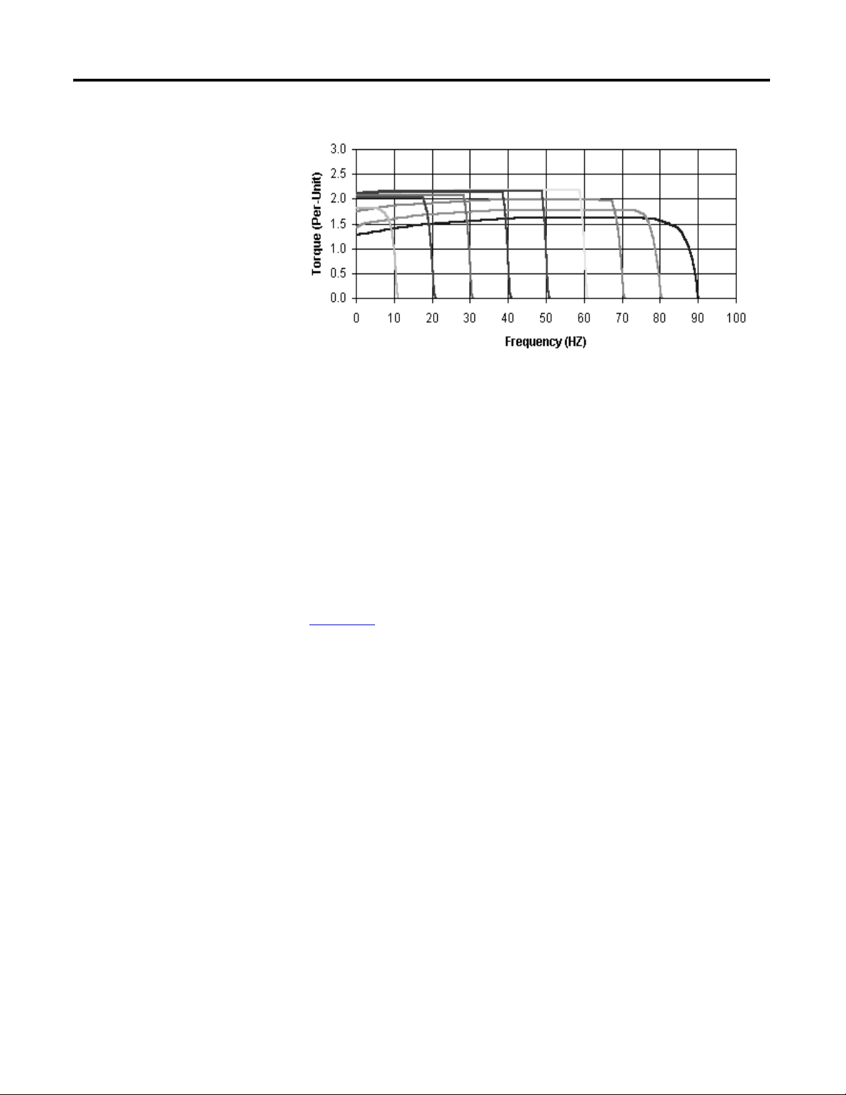
Sensorless Vector Control
Sensorless vector control provides exceptional speed regulation and very high
levels of torque across the entire speed range of the drive. Features include:
• Autotune feature allows the Motor Controller to adapt to individual
motor characteristics.
• Able to develop high torque over a wide speed range and adapts to
individual motor characteristics.
• Embedded Variable Frequency Drive (VFD) control includes the Timer,
Counter, Basic Logic and StepLogic® functions which can reduce hardware
design costs and simplify control schemes.
• Integral PID (proportional, integral, differential) functionality enhances
application flexibility.
Rockwell Automation Publication 280E-UM001B-EN-P - July 2012 19
Page 20
Chapter 1 Product Overview
Figure 4 - Sensorless Vector Control
Description of Features
Embedded Switch Tech nology
Overload Protection
The ArmorStart Distributed Motor Controller incorporates, as standard,
electronic motor overload protection. This overload protection is accomplished
2
electronically with an I
programmable via the communication network, providing the user with
flexibility.
The Bulletin 280E/281E overload trip class can be selected for class 10, 15, 20
protection. The Bulletin 284E overload trip class is Class 10 only. Ambient
insensitivity is inherent in the electronic design of the overload (refer to
Chapter 11
ArmorStart EtherNet/IP includes embedded switch technology as standard.
Each ArmorStart EtherNet/IP will consume one Common Industrial Protocol
(CIP) connection. The ArmoStart will consume a Class 3 connection when
RSLogix 5000 software displays the AOP.
In general, for a DLR or linear network keep individual segments to 50 nodes
or less. In addition, it is important to reserve a minimum of 10% of available
bandwidth to allow for processing of explicit messages.
for the specification for overload trip curves).
t algorithm. The ArmorStart’s overload protection is
Common features are:
• Designed according to the ODVA specification for EtherNet/IP.
ODVA specification found at http://www.odva.org/
• Embedded switch technology is designed to enable end devices to form
linear and ring network topologies
• Supports Device Level Ring (DLR) protocol
20 Rockwell Automation Publication 280E-UM001B-EN-P - July 2012
Page 21

Product Overview Chapter 1
• Supports IEEE 1588 transparent clock for CIP Motion™ and CIP Sync™
applications
• Supports the management of network traffic to ensure timely delivery of
critical data, that is, QoS and IGMP protocols are supported
Note: DLR ports cannot be used as two network interface cards (NICs)
connected to two different subnets.
Switched vs. Unswitched Control Power Input/Output (I/O) Connections
The voltage at terminals A1/A2 supplies power to the Armorstart outputs.
Removing this power or placing the Armorstart disconnect in the “OFF”
position will disable the outputs.
The unswitched power A3/A2 supplies power to the input and communication
module. This power is not affected by the state of the disconnect switch. This
ensures that anytime the controller can communicate, the state of the inputs
is correct.
Figure 5 - Input and Output Configuration
EtherNet/IP™ Ports
ArmorStart EtherNet/IP includes a dual port Ethernet switch that supports
10/100 Mbps It utilizes a sealed D-coded micro (M12) style Ethernet connector.
Dynamic Host Configuration Protocol (DHCP) is enabled as the factory
default. Before using your adapter in an EtherNet/IP network you may need
to configure an IP address or set the address statically.
ATTENTION: To avoid unintended operation, the adapter must be assigned a fixed IP
address. If a DHCP server is used, it must be configured to assign a fixed IP address for
your adapter.
Failure to observe this precaution may result in unintended machine motion or loss
of process control.
Rockwell Automation Publication 280E-UM001B-EN-P - July 2012 21
Page 22
Chapter 1 Product Overview
IMPORTANT
Figure 6 - EtherNet/IP LED
Figure 7 - LED Status
Indication and Reset
Embedded Web Server
EtherNet/IP LED Status Indication
The embedded web server allows the user to view information and configure the
ArmorStart via a web browser. The default Login is “Administrator”. There is no
password set by default.
Caution: The user should set the password to a unique value for authorized
personnel. If the Login and password are lost you will need to reset the device to
factory defaults via the Programmable Logic Controller (PLC). Note: The
configuration will be lost.
E-mail Notification Configuration
The embedded web server supports configuration of the Simple Mail Transfer
Protocol (SMTP). Once properly configured, the motor controller will e-mail
the user with specific fault/trip messages.
EtherNet/IP LED status and diagnostics consists of four LEDs.
Control Module LED Status and Reset
• Link Activity/Status LEDS
– Ethernet Link1 Activity/Status (Port 1) – LED Color: Bicolor
(Green/Yellow)
– Ethernet Link2 Activity/Status (Port 2) – LED Color: Bicolor
(Green/Yellow)
• “MOD” LED – Bicolor Red/Green represents the Ethernet Module status
• “NET” LED – Bicolor Red/Green represents the Ethernet Network status
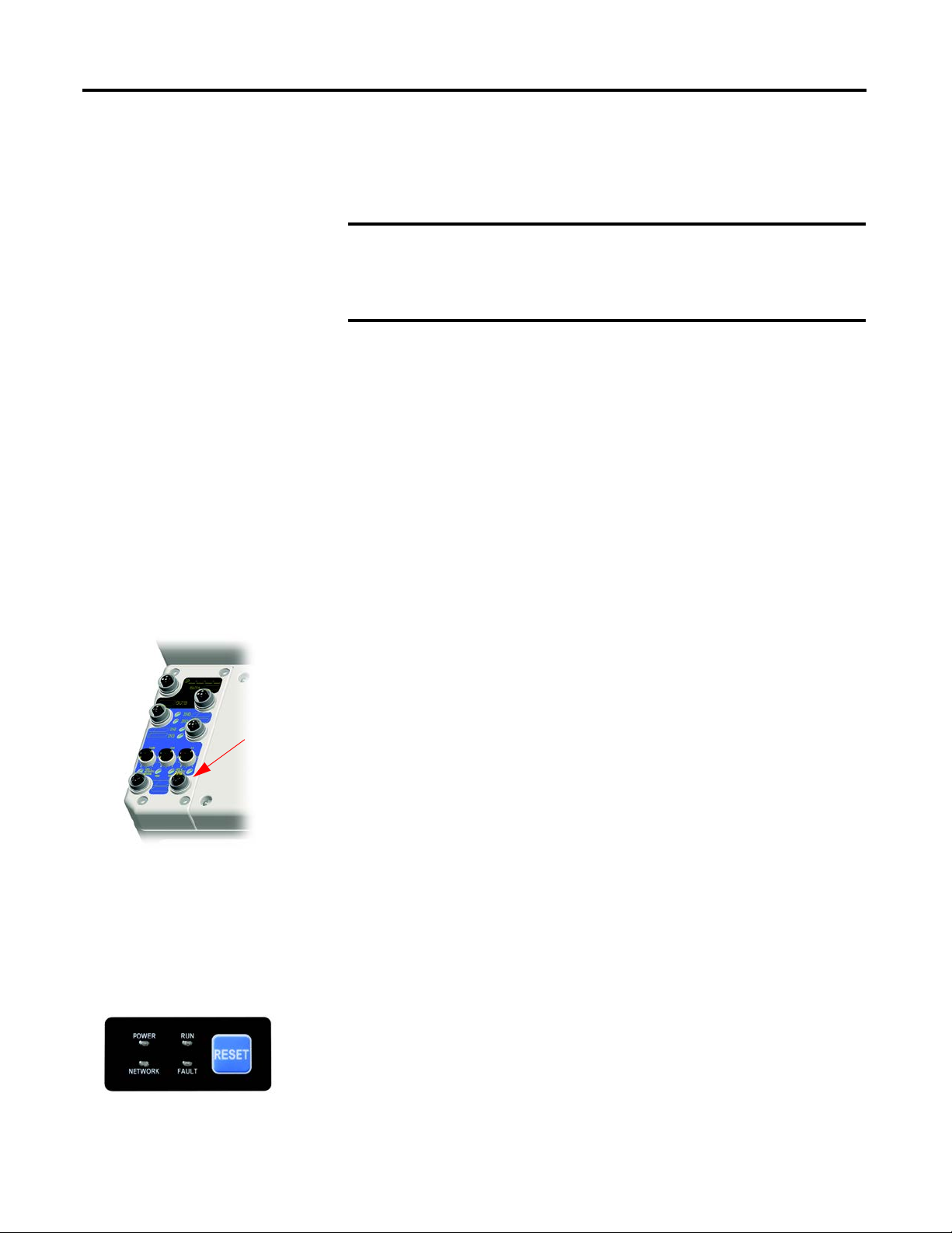
The Control Module LED status and diagnostics consists of four status LEDs
and a Reset button.
• POWER LED
The LED is illuminated solid green when switched (+A1/A2) control
power is present and with the proper polarity.
22 Rockwell Automation Publication 280E-UM001B-EN-P - July 2012
Page 23

Product Overview Chapter 1
• RUN LED
This LED is illuminated solid green when a start command and control
power are present.
• NETWORK LED
This bicolor (red/green) LED indicates the status of the internal
communication link.
• FAULT LED
This indicates a Controller Fault (trip) condition.
The “Reset Button” is a local trip reset.
Electronic Data Sheet (EDS)
Fault Diagnostics
EtherNet/IP devices have electronic data sheets (EDS). These are specially
formatted text files, as defined by the CIP™ Specifications, which represent the
object model of the device. EDS files contain details about the readable and
configurable parameters of the EtherNet/IP device. They also provide
information about the I/O connections the device supports and the content
of the associated data structures. EDS are used by EtherNet/IP device
configuration tools, such as RSNetWorx™ for EtherNet/IP, and data servers
such as RSLinx® Classic.
EDS files for all ArmorStart EtherNet/IP devices can also be uploaded directly
from the device via the web server interface. Rockwell Automation product EDS
files are also available on the internet at: http://www.ab.com/networks/eds.
Fault diagnostics capabilities built in the ArmorStart Distributed Motor
Controller are designed to help you pinpoint a problem for easy troubleshooting
and quick re-starting.
Protection Faults
Protection Faults are generated when potentially dangerous or damaging
conditions are detected. Protection Faults are also known as “Trips.”
Rockwell Automation Publication 280E-UM001B-EN-P - July 2012 23
Page 24

Chapter 1 Product Overview
Table 1 - Protection Faults
Bulletin 280E/281E Trip Status Bulletin 284E Trip Status PowerFlex 40 Fault Codes
Short Circuit Short Circuit —
Overload Overload (Drive Codes 7 and 64)
Phase Loss Phase Short (Drive Codes 38…43)
Reserved Ground Fault (Drive Code 13)
Reserved Stall (Drive Code 6)
Control Pwr Loss Control Pwr Loss —
Input Fault Input Fault —
Over Temperature Over Temperature —
Phase Imbalance Over Current (Drive Codes 12 and 63)
A3, Unswitched Power Loss A3, Unswitched Power Loss —
Reserved Internal Comm (Drive Code 81)
Reserved DC Bus Fault (Drive Codes 3, 4 and 5)
EEprom EEprom (Drive Code 100)
Hdw Flt Hdw Flt (Drive Codes 70 and 122)
Reserved Restart Retries (Drive Code 33)
Reserved Misc. Fault (Drive Codes 2, 8, 29, 48 and 80)
Standard Features
Parameter Group “Start Protection,” Parameter 24 “PrFault Enable” is used to
enable and disable the above protection faults. Refer to Parameter 61
“LastPR Fault” for additional details of the last protection fault.
Inputs
The EtherNet/IP version includes four 24V DC inputs that are single keyed (two
inputs per connector) sourced from A3/A2 control power. The inputs use two
M12 Connectors. Each input has an LED status indication. They are
configurable as sinking or sourcing.
Outputs
The EtherNet/IP version includes two self-protected solid state outputs that are
single keyed (one per connector), sourced from A1/A2 control power. Outputs
are sourcing type with a maximum current per output point of 0.5 A DC. The
outputs use one M12 connectors per output, each having LED status indication.
24 Rockwell Automation Publication 280E-UM001B-EN-P - July 2012
Page 25

Product Overview Chapter 1
Gland Plate Entrance
The ArmorStart product offers two different methods of connecting incoming
three-phase and control power to the device. One method offered is the
traditional conduit entrance with a 3/4 in. and a 1 in. conduit hole opening. The
second method offers connectivity to the ArmorConnect® power media. Factoryinstalled receptacles are provided for connectivity to both three-phase and
control power media.
Motor Cable
With every ArmorStart Distributed Motor Controller, a 3-meter unshielded
4-conductor cordset is provided with each unit as standard. If the optional
Electromagnetic Interference (EMI) Filter is selected for Bulletin 284E units, a
shielded 4-conductor cordset is provided with each unit as standard.
Factory-Installed Options
DeviceLogix™
DeviceLogix is a stand-alone Boolean program that resides within the
ArmorStart Distributed Motor Controller. DeviceLogix is programmed locally
using the Add-On Profile and implements Boolean math operations, such as,
AND, OR, NOT, Timers, Counters, and Latches. DeviceLogix can run as a
stand-alone application, independent of the network. However, 24V DC via A3
unswitched control power, must be maintained.
Optional HOA Keypad Configuration (Bulletin 280E/281E only)
The ArmorStart offers two optional factory-installed Hand/Off/Auto (HOA)
configurations: Standard and Forward/Reverse HOA.
Figure 8 - Optional HOA Configuration (Bulletin 280E left, 281E right)
Rockwell Automation Publication 280E-UM001B-EN-P - July 2012 25
Page 26

Chapter 1 Product Overview
Optional HOA Selector Keypad with Jog Function (Bulletin 284E only)
The HOA Selector Keypad with Jog Function allows for local start/stop control
with capabilities to jog in forward/reverse motor directions.
Figure 9 - Optional HOA with Jog Function Configuration
Source Brake Contactor and Connector (Bulletin 284E only)
An internal contactor is used to switch the electromechanical motor brake On/
Off. The motor brake contactor is powered from the main power circuit. The
configuration of the R1 relay controls the function of the brake. A customer
accessible 2.5 A fuse is provided to protect the brake cable. Included is a 3-meter
3-pin cordset for connection to the motor brake as standard.
EMI Filter (Bulletin 284E only)
The EMI filter is required to be CE compliant. When selected, a 3-meter
shielded 4-conductor motor cordset is provided as standard. This is only available
with sensorless vector control.
Dynamic Brake Connector (Bulletin 284E only)
The user selectable DB Option includes a 3-meter, 3-pin cordset for connection
to a IP20 dynamic brake module. See Chapter 11
modules.
Note: The IP67 Dynamic Brake Resistor cannot be used with the -DB
factory-installed option.
for available dynamic brake
IP67 Dynamic Brake Resistor (Bulletin 284E only)
The IP67 Dynamic Brake Resistor design offers simplicity in wiring and
installation. The user selectable DB1 option provides the quick connector and an
26 Rockwell Automation Publication 280E-UM001B-EN-P - July 2012
Page 27

Product Overview Chapter 1
internal resistor monitoring circuit board. The cable length available is 0.5 m and
1.0 m. The IP67 Dynamic Brake is separately ordered. See Chapter 11
available IP67 Dynamic Brake Resistors.
Note: The IP67 Dynamic Brake Resistor is used only with the -DB1
factory-installed option. Only the specified IP67 Dynamic Brake resistor
can be used based on the VFD horsepower. Connecting resistors other than those
specified will result in a DB1 fault.
for
Output Contactor (Bulletin 284E only)
An internal contactor is sourced from the 24V DC (A1/A2) control voltage
to isolate the load side of the Bulletin 284E ArmorStart Distributed Motor
Controller. When control power is applied to A1/A2, the output contactor will
close. When control power is removed, the output contactor will open. There is
no other switching element that allows alternate control of the output contactor.
A sequenced stop involving the output contactor cannot be performed.
Shielded Motor Cable (Bulletin 284E only)
If the EMI Filter is selected, a 3-meter shielded 4-conductor cordset is provided
as standard.
Rockwell Automation Publication 280E-UM001B-EN-P - July 2012 27
Page 28
Chapter 1 Product Overview
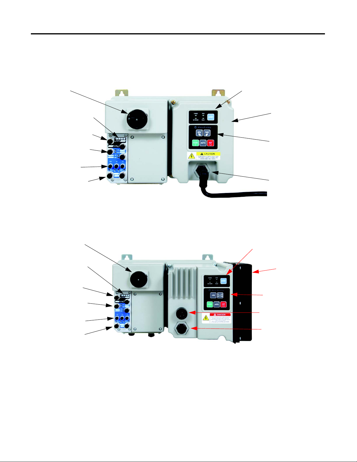
LED Status
Indication and Reset
Motor Connection
4 Inputs (Micro/M12)
IP Address Notation Area
Local Disconnect
2 Outputs (Micro/M12)
Hand-Off-Auto Keypad
IP Address Switches
Control Module
Ethernet Ports (DLR)
LED Status
Indication and Reset
Motor Connection
Source Brake Connection
4 Inputs (Micro/M12)
Ethernet Ports (DLR)
IP Address Switches
IP Address Notation Area
Hand-Off-Auto Keypad
Control Module
Local Disconnect
2 Outputs (Micro/M12)
ArmorStart® EtherNet/ IP Features
Figure 10 - Bulletin 280E/281E ArmorStart with EtherNet/IP™
Communication Protocol
28 Rockwell Automation Publication 280E-UM001B-EN-P - July 2012
Figure 11 - Bulletin 284E ArmorStart with EtherNet/IP Communication Protocol
Page 29

Notes:
Product Overview Chapter 1
Rockwell Automation Publication 280E-UM001B-EN-P - July 2012 29
Page 30

Chapter 1 Product Overview
30 Rockwell Automation Publication 280E-UM001B-EN-P - July 2012
Page 31

Installation and Wiring
IMPORTANT
Chapter 2
Receiving
Unpacking
Inspecting
It is the responsibility of the user to thoroughly inspect the equipment before
accepting the shipment from the freight company. Check the item(s) received
against the purchase order. If any items are damaged, it is the responsibility of the
user not to accept delivery until the freight agent has noted the damage on the
freight bill. Should any concealed damage be found during unpacking, it is again
the responsibility of the user to notify the freight agent. The shipping container
must be left intact and the freight agent should be requested to make a visual
inspection of the equipment.
Remove all packing material, wedges, or braces from within and around the
Armorstart distributed motor controller. Remove all packing material from the
device(s). Check the contents of the package. Contact your local Allen-Bradley
representative if any items are missing.
Before the installation and start-up of the drive, a general inspection of mechanical
integrity (i.e. loose parts, wires, connections, packing materials, etc.) must be made.
After unpacking, check the item(s) nameplate catalog number(s) against the
purchase order. See Chapter 1
which will aid in nameplate interpretation.
for an explanation of the catalog numbering system
Storing
The controller should remain in its shipping container prior to installation. If the
equipment is not to be used for a period of time, it must be stored according to
the following instructions in order to maintain warranty coverage.
• Store in a clean, dry location.
• Store within an ambient temperature range of –25°C…+85°C
(–13°F…+185°F).
• Store within a relative humidity range of 0…95%, noncondensing.
• Do not store equipment where it could be exposed to a corrosive
atmosphere.
• Do not store equipment in a construction area.
Rockwell Automation Publication 280E-UM001B-EN-P - July 2012 31
Page 32

Chapter 2 Installation and Wiring
General Precautions
Precautions for Bulletin 280E/281E Applications
In addition to the precautions listed throughout this manual, the following
statements, which are general to the system, must be read and understood.
ATTENTION: The controller contains ESD (electrostatic discharge) sensitive
parts and assemblies. Static control precautions are required when installing,
testing, servicing, or repairing the assembly. Component damage may result
if ESD control procedures are not followed. If you are not familiar with static
control procedures, refer to Publication 8000-4.5.2
Electrostatic Discharge, or any other applicable ESD protection handbooks.
ATTENTION: An incorrectly applied or installed controller can damage
components or reduce product life. Wiring or application errors, such as
undersizing the motor, incorrect or inadequate AC supply, or excessive
ambient temperatures, may result in malfunction of the system.
ATTENTION: Only personnel familiar with the controller and associated
machinery should plan or implement the installation, startup, and
subsequent maintenance of the system. Failure to do this may result in
personal injury and/or equipment damage.
ATTENTION: To prevent electrical shock, open the disconnect switch prior to
connecting and disconnecting cables. Risk of shock – environment rating
may not be maintained with open receptacles.
, Guarding against
Precautions for Bulletin 284E Applications
WARNING: The drive contains high voltage capacitors which take time to
discharge after removal of mains supply. Before working on a drive, ensure
isolation of mains supply from line inputs (R, S, T [L1, L2, L3]). Wait three
minutes for capacitors to discharge to safe voltage levels. Failure to do so may
result in personal injury or death. Darkened display LEDs are not an indication
that capacitors have discharged to safe voltage levels. Risk of shock –
environment rating may not be maintained with open receptacles.
ATTENTION: Only qualified personnel familiar with adjustable frequency AC
drives and associated machinery should plan or implement the installation,
startup, and subsequent maintenance of the system. Failure to do this may
result in personal injury and/or equipment damage.
32 Rockwell Automation Publication 280E-UM001B-EN-P - July 2012
Page 33

Installation and Wiring Chapter 2
290
11.42[]
287,5
11.32[]
268
10.55[]
6,8
.27[]
39
2[]
47
1.85[]
67,9
3[]
3,02
.12[]
373
14.69[]
11
.43[]
195
7.68[]
189
7[]
OR CONNECTION 185 [7.3] M22 CORDSETMOT
MOTOR ECTION 243 [9.57] M35 CORDSETCONN
150
6[]
351
13.82[]
0.75 in. CONDUIT OPENING
1 in. CONDUIT OPENING
Dimensions
Dimensions are shown in millimeters (inches). Dimensions are not intended to
be used for manufacturing purposes. All dimensions are subject to change.
Conduit Gland Entrance Bulletin 280E/281E
Figure 12 - Dimensions for Bulletin 280E/281E
Rockwell Automation Publication 280E-UM001B-EN-P - July 2012 33
Page 34

Chapter 2 Installation and Wiring
290
11.42[]
287,5
11.32[]
268
10.55[]
6,8
.27[]
39
2[]
47
1.85[]
67,9
3[]
3,02
.12[]
373
14.69[]
11
.43[]
195
7.68[]
236
9[]
2HP or less 420.38 [16.55]
3HP or greater 444.38 [17.50]
R CONNECTION 266.9 [10.51]MOTO
0.75 in. CONDUIT OPENING
1 in. CONDUIT OPENING
Conduit Gland Entrance Bulletin 284E
Figure 13 - Dimensions for Bulletin 284E
34 Rockwell Automation Publication 280E-UM001B-EN-P - July 2012
Page 35

Installation and Wiring Chapter 2
203.2
[8]
CABLE
KEEP OUT
203.2
[8]
CABLE
KEEP OUT
68
2.68[]
60,6
2[]
77,6
3[]
25,5
1[]
351
13.82[]
290
11.42[]
287,5
11.32[]
268
10.55[]
6,8
.27[]
25,5
1[]
68
2.68[]
60,6
2[]
77,6
3[]
351
13.82[]
290
11.42[]
268
10.55[]
287,5
11.32[]
6,8
.27[]
10 Hp @ 480V AC
3 Hp and less @ 480V AC
25 A Short Circuit
Protection (M35)
10 A Short Circuit
Protection (M22)
ArmorConnect® Gland Connectivity Bulletin 280E/281E
Figure 14 - Dimensions for Bulletin 280E/281E
Rockwell Automation Publication 280E-UM001B-EN-P - July 2012 35
Page 36

Chapter 2 Installation and Wiring
68
2.68[]
60,6
2[]
77,6
3[]
25,5
1[]
419,53
16.52[]
290
11.42[]
287,5
11.32[]
268
10.55[]
6,8
.27[]
25,5
1[]
68
2.68[]
60,6
2[]
77,6
3[]
444,38
17.50[]
290
11.42[]
30,4
1[]
287,5
11.32[]
268
10.55[]
6,8
.27[]
3 Hp or greater at 480V
2 Hp or less at 480V
25 A Short Circuit
Protection (M35)
10 A Short Circuit
Protection (M22)
ArmorConnect Gland Connectivity Bulletin 284E
Figure 15 - Dimensions for Bulletin 284E
36 Rockwell Automation Publication 280E-UM001B-EN-P - July 2012
Page 37

Installation and Wiring Chapter 2
IMPORTANT
Mount Orientation
The recommended mounting orientation of ArmorStart EtherNet/IP is the
vertical configuration. This is especially important for the Bulletin 284. This
ensures proper air flow over the heat sink. Improper mounting or debris build up
will reduce air flow and increased internal temperatures. This may reduce the
overall life of the product. For alternate mounting contact your local sales
representative.
For proper heat dissipation and product operation, mount in the vertical orientation
as shown.
Operation
Wiring
The ArmorStart Distributed Motor Controllers can operate three-phase
squirrel-cage induction motors as follows:
Bulletin 280E/281E: 0.24…16 A; 200V AC, 230V AC, 460V AC; 50/60 Hz.
Bulletin 284E: up to 5 Hp (3.0 kW) @ 480V AC
The ArmorStart EtherNet/IP Distributed Motor Controller will accept a control
power input of 24V DC.
Power, Control, Safety Monitor Inputs, and Ground Wiring
Table 2 provides the power, control, and ground wire capacity and the tightening
torque requirements. The power, control, ground, and safety monitor terminals
will accept a maximum of two wires per terminal.
Table 2 - Power, Control, Safety Monitor Inputs, Ground Wire Size, and Torque Specifications
Terminals Wire Size Torque Wire Strip Length
Primary Terminal:
10.8 lb-in.
(1.2 N•m)
Secondary Terminal:
4.5 lb-in.
(0.5 N•m)
6.2 lb-in.
(0.7 N•m)
0.35 in. (9 mm)
0.35 in. (9 mm)
Power
and
Ground
Control Inputs
Primary/Secondary
Ter min al :
1.5…4.0 mm
(#16 …#10 American Wire
Gage (AWG))
1.0 mm
(#18…#10 AWG)
2
…4.0 mm2
2
Rockwell Automation Publication 280E-UM001B-EN-P - July 2012 37
Page 38

Chapter 2 Installation and Wiring
See Detail A
Detail A
Terminal Designations
As shown in Figure 16, the ArmorStart Distributed Motor Controller contains
terminals for power, control, and ground wiring. Access can be gained by
removing the terminal access cover plate.
Figure 16 - ArmorStart Power and Control Terminal Connections
(applies to Bulletin 280E/281E and Bulletin 284E)
Control Power Wiring
Table 3 - Power, Control and Ground Terminal Designations
Terminal Designations No. of Poles Description
A1 (+) 2 Control Power Input
A2 (–) 2 Control Power Common
A3 (+) 2 Unswitched 24V Control
PE 2 Ground
1/L1 2 Line Power Phase A
3/L3 2 Line Power Phase B
5/L5 2 Line Power Phase C
ArmorStart EtherNet/IP utilizes 24V DC control power for communications
and I/O. The control power terminal connections are labeled A1, A2, and A3.
Switched power will supply the outputs. Unswitched power will supply logic
power and sensor inputs.
38 Rockwell Automation Publication 280E-UM001B-EN-P - July 2012
Page 39

Installation and Wiring Chapter 2
24V DC Control Power
• 24V DC (–15%, +10%)
• A1 = Switched +V
• A2 = Common for both switched and unswitched (–V)
• A3 = Unswitched +V
Input and Output Characteristics
• 5-pin female connectors (M12)
• 4 fixed inputs (two per connector) – software selectable sink or source
• 2 sourcing outputs DC (solid-state) – (one per connector)
Input and Output Power Connection
• Sensor Power will be sourced from +24V supplied from A3(+) and A2(–).
•
Output power will be sourced from +24V supplied from A1(+) and A2(–).
• Max. current per output point is 0.5 A and is not to exceed 1.0 A total
Rockwell Automation Publication 280E-UM001B-EN-P - July 2012 39
Page 40

Chapter 2 Installation and Wiring
Input 0
Input 1
Input 2
Input 3
4 Inputs
50mA Max/input depends
on sensor attached to input
A1
A2
26V
24V DC
11 -
25V DC
+24V DC Status
5V DC
11 -
25V DC
+5V DC
AS Logic Circuits
140M Trip
140M Status
F
A
Not Used
Input 10mA @ 24V DC
Input 10mA @ 24V DC
Input 10mA @ 24V DC
Input 10mA @ 24V DC
Current supplied by
control power due to the
power supply voltage
being greater than A3
voltage
Reversed bias
under normal
operation
Current supplied from A3 when
A1 control power is lost
Output A
Output B
1 Ampere
Total
140M
O/Tripped
On
7A
Class CC
2.5A
Class CC
AS Logic
Control
Power
Sense
PTC
Short
Detect
Motor
F
140M
300mA Max
A3
24V
AS Logic
Control
L1
L2
L3
Ethernet
Logic
2A SC Protected
2A SC Protected
Port 1Port 2
Note: This power supply is not
present in the Status Only versions.
ArmorStart with EtherNet/IP Internal Wiring
Figure 17 - ArmorStart Ethernet Bulletin 280E with HOA Diagram
40 Rockwell Automation Publication 280E-UM001B-EN-P - July 2012
Page 41

Figure 18 - ArmorStart Ethernet Bulletin 281E with HOA Diagram
Input 0
Input 1
Input 2
Input 3
4 Inputs
50mA Max/input depends
on sensor attached to input
A1
A2
26V
24V DC
11 -
25V DC
+24V DC Status
5Vdc
11 -
25Vdc
+5V DC
AS Logic Circuits
140M Trip
140M Status
F
A
Not Used
Input 10mA @ 24V DC
Input 10mA @ 24V DC
Input 10mA @ 24V DC
Input 10mA @ 24V DC
Current supplied by
control power due to the
power supply voltage
being greater than A3
voltage
Reversed bias
under normal
operation
Current supplied from A3 when
A1 control power is lost
Output A
Output B
1 Ampere
Total
ArmorStart Ethernet REV with HOA Diagram
140M
O/Tripped
On
7A
Class CC
2.5A
Class CC
AS Logic
Control
Power
Sense
PTC
Short
Detect
Motor
F
140M
300mA Max
A3
24V
AS Logic
Control
L1
L2
L3
Ethernet
Logic
Reverser
R
R
B
F
B
AS Logic
Control
2A SC Protected
2A SC Protected
Port 2
Port 1
Note: This power supply is not
present in the Status Only versions.
Installation and Wiring Chapter 2
Rockwell Automation Publication 280E-UM001B-EN-P - July 2012 41
Page 42

Chapter 2 Installation and Wiring
Input 0
Input 1
Input 2
Input 3
4 Inputs
50mA Max/input depends
on sensor attached to input
26V
24V DC
Fan
24V DC
11 -
25V DC
+24V DC Status
5V DC
11 -
25V DC
+5V DC
AS Logic
Circuits
140M Trip
140M Status
Brake CNTR Status
Output CNTR Status
1
Input 10mA @ 24V DC
Input 10mA @ 24V DC
Input 10mA @ 24V DC
Input 10mA @ 24V DC
Current supplied by
control power due to the
power supply voltage
being greater than A3
voltage
Reversed bias
under normal
operation
Current supplied by
A3 when A1 control
power is lost
Sensorless Vector Control
Filter
Option
140M
O/Tripped
On
7A
Class CC
2.5A
Class CC
AS Logic
Control
Power
Sense
Output
Contactor
O
PTC
Short
Detect
Motor
Source Brake
Option
B
PF40
R1
R2
L1
L2
L3
T1
T2
T3
R1
R2
R3
01
02
040506 07
08 09
11
12
13
14
15
16
17
18 19
03
BR+ BR-
Dynamic Brake
Connector
Option
RJ-45
300mA Max
Note: This switch is controlled
by the Control Power Logic
sense. If control power is
present, switch is closed.
Prevents drive from running
when there is no power for the
fan
1 - Output CNTR Status not
available when SM option specied
Output Contactor
Option
Source Brake
Option
3A
Class CC
A3
Ethernet
Logic
A1
A2
Output A
Output B
1 Ampere
Total
L1
L2
L3
2A SC Protected
2A SC Protected
Port 2Port 1
140M
Figure 19 - ArmorStart Ethernet Bulletin 284E Drive Diagram
42 Rockwell Automation Publication 280E-UM001B-EN-P - July 2012
Page 43

Installation and Wiring Chapter 2
3/4 in. Lock Nut 1 in. Lock Nut
Thomas & Betts Cord Grip
Cat. No. 2931NM
3/4 in. Stain Relief Cord Connector
Cable Range: 0.31…0.56 in.
Used with Control Power Media
Cordset - Example :
Cat. No. 889N-M65GF-M2
Thomas & Betts Cord Grip
Cat. No. 2940NM
1 in. Stain Relief Cord Connector
Cable Range: 0.31…0.56 in.
Used with Three-Phase Power
Media Cordset - Example:
Cat. No. 280-PWR22G-M1
3/4 in. Lock Nut 1 in. Lock Nut
Thomas & Betts Cord Grip
Cat. No. 2931NM
3/4 in. Stain Relief Cord Connector
Cable Range: 0.31…0.56 in.
Used with Control Power Media
Cordset - Example:
Cat. No. 889N-M65GF-M2
Thomas & Betts Cord Grip
Cat. No. 2942NM
1 in. Stain Relief Cord Connector
Cable Range: 0.70…0.95 in.
Used with Three-Phase Power
Media Cordset - Example:
Cat. No. 280-PWR35G-M1
Recommended Cord Grips
Figure 20 - Cord grips for ArmorStart Devices with 10 A Short Circuit Protection Rating
Figure 21 - Cord grips for ArmorStart Devices with 25 A Short Circuit Protection Rating
AC Supply Considerations for Bulletin 284E Units
Ungrounded and High Resistive Distribution Systems
ATTENTION: The Bulletin 284E contains protective Metal Oxide Varistors
(MOVs) that are referenced to a ground. These devices should be disconnected
if the Bulletin 284E is installed on an ungrounded and high resistive
distribution system.
ATTENTION: Do not remove this jumper, shown in Figure 23, if the unit is
equipped with an EMI filter installed.
Rockwell Automation Publication 280E-UM001B-EN-P - July 2012 43
Page 44
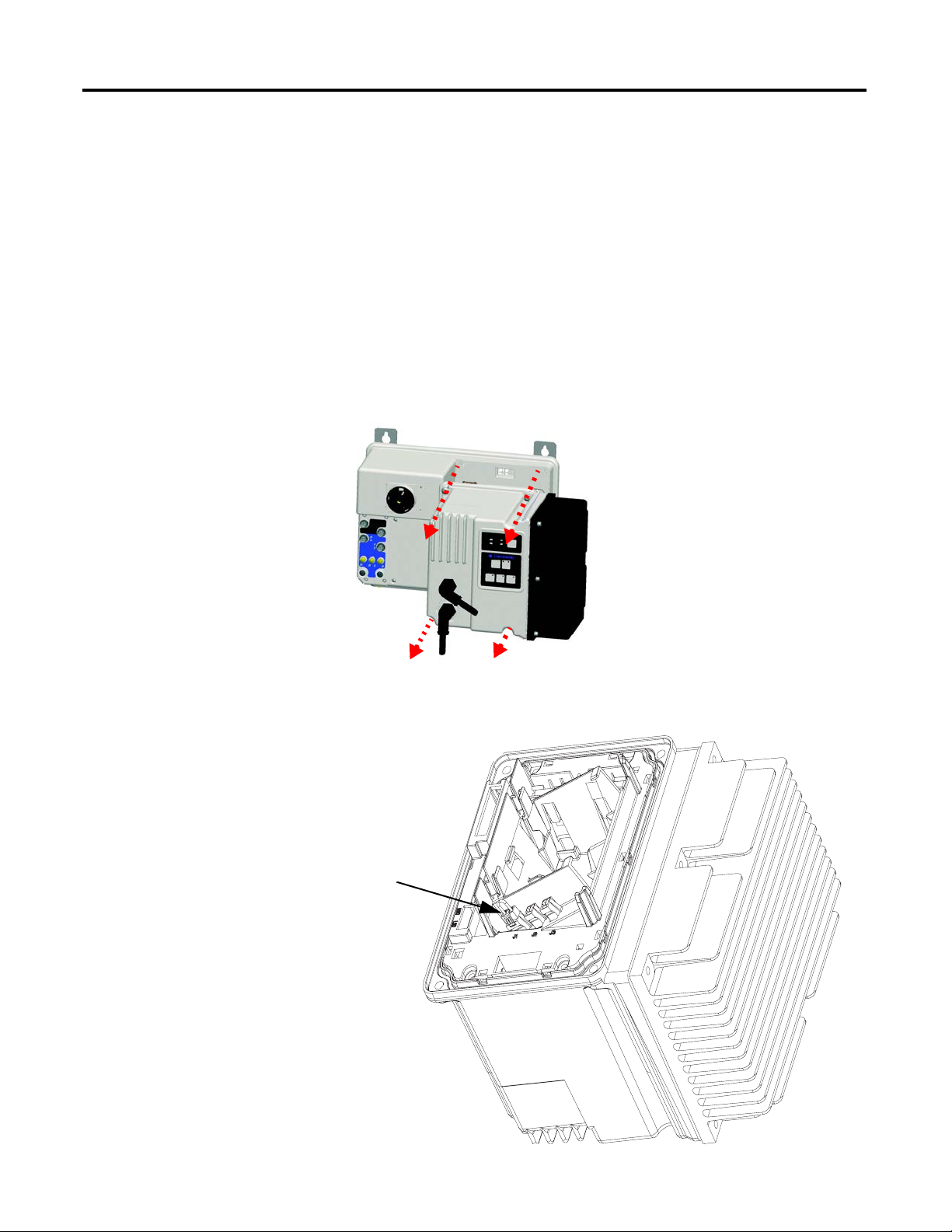
Chapter 2 Installation and Wiring
Remove Jumper
Disconnecting MOVs
To prevent drive damage, the MOVs connected to ground must be disconnected
if the drive is installed on an ungrounded and high resistive distribution system
where the line-to-ground voltages on any phase could exceed 125% of the
nominal line-to-line voltage. To disconnect the MOVs, remove the jumper shown
in Figure 23, Bulletin 284E Jumper Removal.
1. Before installing the Bulletin 284E, loosen four mounting screws.
2. Unplug control module from the base unit by pulling forward.
Figure 22 - Bulletin 284E Removal of Control Module
Figure 23 - Bulletin 284E Jumper Removal
44 Rockwell Automation Publication 280E-UM001B-EN-P - July 2012
Page 45

Installation and Wiring Chapter 2
Group Motor Installations for USA and Canada Markets
The ArmorStart Distributed Motor controllers are listed for use with each other
in group installations per NFPA 79, Electrical Standard for Industrial Machinery.
When applied according to the group motor installation requirements, two or
more motors, of any rating or controller type, are permitted on a single branch
circuit. Group Motor Installation has been successfully used for many years in the
USA and Canada.
Note: For additional information regarding group motor installations with the
ArmorStart Distributed Motor Controller, see Appendix A
.
Wiring and Workmanship Guidelines
In addition to conduit and seal-tite raceway, it is acceptable to utilize cable that is
dual rated Tray Cable Exposed Runs (TC-ER) and Cord, STOOW, for power
and control wiring on ArmorStart installations. In the USA and Canada
installations, the following guidance is outlined by the National Electrical Code
(NEC) and National Fire Protection Association (NFPA) 79.
In industrial establishments where the conditions of maintenance and
supervision ensure that only qualified persons service the installation, and where
the exposed cable is continuously supported and protected against physical
damage using mechanical protection, such as struts, angles, or channels, Type TC
tray cable that complies with the crush and impact requirements of Type MC
(Metal Clad) cable and is identified for such use with the marking Type TC-ER
(Exposed Run)* shall be permitted between a cable tray and the utilization
equipment or device as open wiring. The cable shall be secured at intervals not
exceeding 1.8 m (6 ft) and installed in a “good workman-like” manner.
Equipment grounding for the utilization equipment shall be provided by an
equipment grounding conductor within the cable.
*Historically cable meeting these crush and impact requirements were designated
and marked “Open Wiring”. Cable so marked is equivalent to the present Type
TC-ER and can be used.
While the ArmorStart is intended for installation in factory floor environments
of industrial establishments, the following must be taken into consideration when
locating the ArmorStart in the application:
• Cables, including those for control voltage including 24V DC and
communications, are not to be exposed to an operator or building traffic
on a continuous basis.
• Location of the ArmorStart to minimize exposure to continual traffic is
recommended. If location to minimize traffic flow is unavoidable, other
barriers to minimize inadvertent exposure to the cabling should be
considered.
Rockwell Automation Publication 280E-UM001B-EN-P - July 2012 45
Page 46

Chapter 2 Installation and Wiring
• Routing cables should be done in such a manner to minimize inadvertent
exposure and/or damage.
• Additionally, if conduit or other raceways are not used, it is recommended
that strain relief fittings be utilized when installing the cables for the
control and power wiring through the conduit openings.
The working space around the ArmorStart may be minimized as the ArmorStart
does not require examination, adjustment, servicing or maintenance while
energized. In lieu of this service, the ArmorStart is meant to be unplugged and
replaced after proper lockout/tag-out procedures have been employed.
The Hand-Off-Auto (HOA) is a factory-installed option that the user may select.
The HOA keypad may require the ArmorStart to be selected and installed as
follows if the application requires frequent use of the hand operated interface by
the equipment operator:
1. They are not less than 0.6 m (2 ft) above the servicing level and are within
easy reach of the normal working position of the operator.
Electromagnetic Compatibility (EMC)
2. The operator is not placed in a hazardous situation when operating them.
3. The possibility of inadvertent operation is minimized.
If the operated interface is used in industrial establishments where the conditions
of maintenance and supervision ensure that only qualified persons operate and
service the ArmorStart's operator interface, and the installation is located so that
inadvertent operation is minimized, then other installation locations with
acceptable access can be provided.
Other System Design Considerations
The user should keep 3-phase power cabling at least 6 in. away from the
EtherNet/IP network to avoid noise issues. EtherNet/IP is an unpowered
network therefore if device status is important when the disconnect is in the OFF
position, the A3 terminal must have an unswitched power source.
The following guidelines are provided for EMC installation compliance.
General Notes (Bulletin 284E only)
• The motor Cable should be kept as short as possible in order to avoid
electromagnetic emission as well as capacitive currents.
• Conformity of the drive with CE EMC requirements does not guarantee
an entire machine installation complies with CE EMC requirements.
Many factors can influence total machine/installation compliance.
46 Rockwell Automation Publication 280E-UM001B-EN-P - July 2012
Page 47

Installation and Wiring Chapter 2
• Using an EMI filter, with any drive rating, may result in relatively high
ground leakage currents. Therefore, the filter must only be used in
installations that are solidly grounded (bonded) to the building power
distribution ground. Grounding must not rely on flexible cables and
should not include any form of plug or socket that would permit
inadvertent disconnection. Some local codes may require redundant
ground connections. The integrity of all connections should be
periodically checked.
Wiring
Wire in an industrial control application can be divided into three groups: power,
control, and signal. The following recommendations for physical separation
between these groups is provided to reduce the coupling effect:
• Minimum spacing between different wire groups in the same tray should
be 6 in. (16 cm).
Grounding
• Wire runs outside an enclosure should be run in conduit or have shielding/
armor with equivalent attenuation.
• Different wire groups should be run in separate conduits.
• Minimum spacing between conduits containing different wire groups
should be 3 in. (8 cm).
An effectively grounded product is one that is “intentionally connected to earth
through a ground connection or connections of sufficiently low impedance and
having sufficient current-carrying capacity to prevent the buildup of voltages
which may result in undue hazard to connected equipment or to persons” (as
defined by the US National Electric Code NFPA70, Article 100B). Grounding
is done for two basic reasons: safety (defined above) and noise containment or
reduction. While the safety ground scheme and the noise current return circuit
may sometimes share the same path and components, they should be considered
different circuits with different requirements.
Grounding Safety Grounds
The object of safety grounding is to ensure that all metalwork is at the same
ground (or Earth) potential at power frequencies. Impedance between the drive
and the building scheme ground must conform to the requirements of national
and local industrial safety regulations or electrical codes. These will vary based
on country, type of distribution system and other factors. Periodically check the
integrity of all ground connections.
Rockwell Automation Publication 280E-UM001B-EN-P - July 2012 47
Page 48

Chapter 2 Installation and Wiring
IMPORTANT
General safety dictates that all metal parts are connected to earth with separate
copper wire or wires of the appropriate gauge. Most equipment has specific
provisions to connect a safety ground or PE (protective earth) directly to it.
Grounding PE or Ground
The safety ground - PE must be connected to earth ground. This point must
be connected to adjacent building steel (girder, joist), a floor ground rod, bus bar
or building ground grid. Grounding points must comply with national and local
industrial safety regulations or electrical codes. Some codes may require
redundant ground paths and periodic examination of connection integrity.
To avoid electrolytic corrosion on the external earth terminal, avoid spraying
moisture directly on the terminal. When used in washdown environments
apply a sealant or other corrosion inhibitor on the external ground terminal
to minimize any negative effects of galvanic or Electro-chemical corrosion.
Ground connections should be inspected on a regular basis.
ArmorConnect Power Media
Grounding Motors
The motor frame or stator core must be connected directly to the PE connection
with a separate ground conductor. It is recommended that each motor frame be
grounded to building steel at the motor.
Description
The ArmorConnect power media offers both three-phase and control power
cable cord set systems including patchcords, receptacles, tees, reducers and
accessories to be utilized with the ArmorStart Distributed Motor Controller.
These cable system components allow quick connection of ArmorStart
Distributed Motor Controllers, reducing installation time. They provide for
repeatable, reliable connection of the three-phase and control power to the
ArmorStart Distributed Motor Controller and motor by providing a plug-andplay environment that also avoids system mis-wiring. When specifying power
media for use with the ArmorStart Distributed Motor Controllers (Bulletin
280E/281E and Bulletin 284E) use only the Bulletin 280E ArmorConnect
power media.
Refer to the On-Machine Selection Catalog for ordering details. The following
shows example configurations for power, control, and communication media.
48 Rockwell Automation Publication 280E-UM001B-EN-P - July 2012
Page 49

Figure 24 - Ethernet Media System Overview
Installation and Wiring Chapter 2
Connections:
➊ CAT5e Bulkhead Connector and Receptacle – Example Cat.No. 1585A-DD4JD
➋ CAT5e Patchcord, IP67, M12 D-Code, Male Straight, Male Right Angle – Example Cat.No. 1585D-M4TBDE-*
➌ CAT5e, Patch Cable, IP20, RJ45 Male to RJ45 Male – Example Cat.No. 1585J-M4TB-*
➍ Three-Phase Power Receptacles -
Female receptacles are a panel mount connector with flying leads – Example Cat. No. 280-M35F-M1
➎ Three-Phase Power Trunk- Patchcord cable with integral female or male connector on each end –
Example Cat. No. 280-PWR35A-M*
➏ Three-Phase Drop Cable- Patchcord cable with integral female or male connector on each end –
Example Cat. No. 280-PWR22A-M*
➐ Three-Phase Power Tees and Reducer –
Tee connects to a single drop line to trunk with quick change connectors – Cat. No. 280-T35
Reducing Tee connects to a single drop line (Mini) to trunk (Quick change) connector – Cat. No. 280-RT35
Reducer connects from quick change male connector to mini female connector – Cat. No. 280-RA35
➑ Control Power Receptacles - Female receptacles are a panel mount connector with flying leads –
Cat. No. 888N-D65AF1-*
➒ Control Power Media Patchcords – Patchcord cable with integral female or male connector on each end –
Example Cat. No. 889N-F65GFNM-*
➓ Control Power Tees - The E-stop In Tee (Cat. No. 898N-653ST-NKF) is used to connect to the Bulletin 800F On-
Machine E-Stop station using a control power media patchcord. The E-stop Out tee (Cat. No. 898N-653ES-
NKF) is used with cordset or patchcord to connect to the ArmorStart Distributed Motor Controller.
Rockwell Automation Publication 280E-UM001B-EN-P - July 2012 49
Page 50

Chapter 2 Installation and Wiring
Control Power Receptacl e
Three-Phase Power Receptacle
Control Power Rece ptacle
Three-Phase Power Receptacle
10 A Short Circuit Protection Rating 25 A Short Circuit Protection Rating
ArmorConnect Connections
Figure 25 - ArmorConnect Receptacles
Factory-installed ArmorConnect gland plate connections
Figure 26 - ArmorConnect Connections
Table 4 - ArmorConnect Gland Plate Conductor Color Code
Terminal Designations Description Color Code
A1 (+) Control Power Input Blue
A2 (–) Control Power Common Black
A3 (+) Unswitched Control Power Red
PE Ground Green/Yellow
1/L1 Line Power – Phase A Black
2/L2 Line Power – Phase B White
3/L3 Line Power – Phase C Red
50 Rockwell Automation Publication 280E-UM001B-EN-P - July 2012
Page 51

Figure 27 - On-Machine Stop Stations
Table 1 Product Selection
Installation and Wiring Chapter 2
Illumination
Enclosure Type Quick Connect Knockout Type Operator
Plastic
Metal 24V AC/DC 800F-1MYMQ4
Mini Receptacle Metric Twist to Release
Volt age
24V AC/DC
Contact
Configuration
1 N.C./1 N.O.
Figure 28 - Stop Circuit for EtherNet/IP Version
Cat. No.
800F-1YMQ4
Rockwell Automation Publication 280E-UM001B-EN-P - July 2012 51
Page 52

Chapter 2 Installation and Wiring
ArmorConnect Cable Ratings
The ArmorConnect Power Media cables are rated per UL Type TC
600V 90°C Dry 75°C Wet, Exposed Run (ER) or MTW 600V 90°C or
STOOW 105°C 600V - Canadian Standards Association (CSA) STOOW 600V
FT2. For additional information regarding ArmorConnect Power Media refer to
the Industrial Controls Catalog.
Branch Circuit Protection Requirements for ArmorConnect Three-Phase Power Media
When using ArmorConnect Three-Phase Power Media, fuses or circuit breakers
can be used for the motor branch circuit protective device, for the group motor
installations.
For 25 A rated ArmorConnect cable for trunk and taps:
Circuit Breaker: Suitable for use on a circuit capable of delivering not more than
65 000 RMS symmetrical amperes at 480V AC maximum when protected by
Bulletin 140U-H frame circuit breaker, not rated more than 480V, 100 A and a
maximum interrupting of 65 000 RMS symmetrical amperes Short Circuit
Current Rating (SCCR).
Fusing: Suitable for use on a circuit capable of delivering not more than 65 000
RMS symmetrical amperes (SCCR) at 600V AC maximum when protected by
CC, J, and T class fuses.
For 10 A and 15 A rated ArmorConnect taps:
Circuit Breaker: Suitable for use on a circuit capable of delivering not more than
45 000 RMS symmetrical amperes at 480Y/277V AC maximum when protected
by Cat. No. 140U-D6D3-C30 circuit breaker, not rated more than 480V, 30 A,
having an interrupting rating not less than 45 000 RMS symmetrical amperes,
480Y/277V AC maximum.
WARNING: The total circuit impedance including each cable assembly's own
impedance, must be low enough to ensure any short- circuit or ground fault current that
can flow through any assembly, will be large enough to operate the magnetic trip of the
Cat. No. 140U-D63-C* circuit breaker. Refer to your local electrical code for acceptable
practices for this evaluation.
Fusing: Suitable for use on a circuit capable of delivering not more than 65 000
RMS symmetrical amperes (SCCR) at 600V AC maximum when protected by
CC, J, and T class fuses, rated 40 A non-time delay or 20 A time delay.
52 Rockwell Automation Publication 280E-UM001B-EN-P - July 2012
Page 53
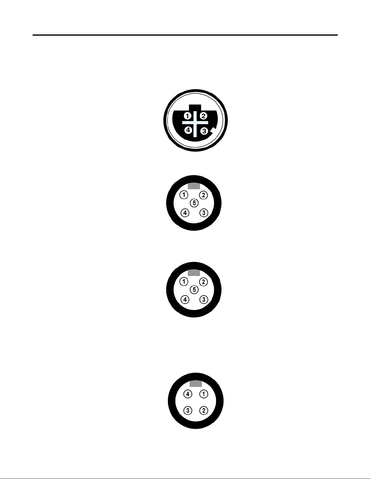
Installation and Wiring Chapter 2
M12 Female Ethernet Connector
(view into connec tor)
Pin 1 - Tx+
Pin 2 - Rx+
Pin 3 - Tx–
Pin 4 - Rx–
Pin 1 - +24V (A3 pwr)
Pin 2 - Input 0
Pin 3 - Common
Pin 4 - Input 1
Pin 5 - NC (no connection)
Pin 1 - NC (no connection)
Pin 2 - NC (no connection)
Pin 3 - Common
Pin 4 - Output +24V DC (A1 pwr)
Pin 5 - NC (no connection)
Pin 1 - T1 (black)
Pin 2 - T2 (white)
Pin 3 - T3 (red)
Pin 4 - Ground (green/yellow)
Ethernet and I/O Connections
ArmorStart EtherNet/IP utilizes a sealed D-coded M12 (micro) style
Ethernet connector.
Figure 29 - Ethernet/IP Connector
Figure 30 - I/O Receptacle Input Pin Out (M12)
Power Connections
Figure 31 - I/O Receptacle Output Pin Out (M12)
Figure 32 - External Connections for Motor Connector – Bulletin 284E - 5 Hp and
Bulletin 280E/281E - 3 Hp or less (M22) at 480V AC
Rockwell Automation Publication 280E-UM001B-EN-P - July 2012 53
Page 54

Chapter 2 Installation and Wiring
Pin 1 - T1 (black)
Pin 2 - Ground (green/yellow)
Pin 3 - T3 (red)
Pin 4 - T2 (white)
Pin 1 - L1 (black)
Pin 2 - Ground (green/yellow)
Pin 3 - L2 (white)
Pin 1 - Ground (green/yellow)
Pin 2 - BR+ (black)
Pin 3 - BR– (white)
Pin 1 - +24V DC unswitched (A3/red)
Pin 2 - Common (A2/black)
Pin 3 - PE (green)
Pin 4 - Not used (blank)
Pin 5 - +24V DC switched (A1/blue)
Pin 6 - Not used (white)
Figure 33 - External Connections for Motor Connector – Bulletin 280E/281E - 10 Hp (M35)
at 480V AC
Figure 34 - External Connections for Brake Contactor Connector (M25)
Figure 35 - External Connections for Dynamic Brake Connection (M22)
Figure 36 - Incoming Control Power (M22) – 24V DC Only
54 Rockwell Automation Publication 280E-UM001B-EN-P - July 2012
Page 55

Installation and Wiring Chapter 2
Pin 1 - L1 (black)
Pin 2 - L2 (white)
Pin 3 - L3 (red)
Pin 4 - Ground (green/yellow)
Pin 1 - L1 (black)
Pin 2 - Ground (green/yellow)
Pin 3 - L3 (red)
Pin 4 - L2 (white)
Figure 37 - Incoming Three-Phase Power for 10 A Short Circuit Protection (M22)
Figure 38 - Incoming Three-Phase Power for 25 A Short Circuit Protection (M35)
Optional Locking Clip
The clam shell design clips over the ArmorStart motor connector and motor
cable to limit customer access from disconnecting the motor cable on the
ArmorStart Distributed Motor Controller. The locking clip is an optional device
that can be used, if desired. A locking clip is not available for the M25 Source
Brake connection.
Figure 39 - Bulletin 280E/281E Installation of Locking Clip
Rockwell Automation Publication 280E-UM001B-EN-P - July 2012 55
Page 56

Chapter 2 Installation and Wiring
Figure 40 - Bulletin 284E Installation of Locking Clip
56 Rockwell Automation Publication 280E-UM001B-EN-P - July 2012
Page 57

Introduction to EtherNet/IP and Device Level Ring Technology
Chapter 3
Terminology
Refer to the table for the meaning of common terms.
This Term Means
Consumer A destination device in the CIP™ networking model. See CIP.
CSMA/CD Carrier sense multiple access/collision detection is the access method used in
Ethernet. When a device wants to gain access to the network, it checks to see if
the network is quiet (senses the carrier). If it is not, it waits a random amount of
time before retrying. If the network is quiet and two devices access the line at
exactly the same time, their signals collide. When the collision is detected, they
both back off and each waits a random amount of time before retrying.
Determinism The ability to predict when information will be delivered. Important in time-
critical applications.
DHCP The dynamic host configuration protocol is an Internet protocol, similar to BootP,
for automating the configuration of computers that use TCP/IP. DHCP can be
used to automatically assign IP addresses, to deliver IP stack configuration
parameters, such as the subnet mask and default router, and to provide other
configuration information, such as the addresses for printer, time, and news
servers.
DNS The domain name system is a hierarchical, distributed method of organizing the
name space of the Internet. The DNS administratively groups hosts into a
hierarchy of authority that allows addressing and other information to be
widely distributed and maintained. A big advantage to the DNS is that using it
eliminates dependence on a centrally-maintained file that maps host names to
addresses.
Ethernet A physical layer standard using carrier sense multiple access with collision
detection (CSMA/CD) methods.
EtherNet/IP Ethernet industrial protocol applies a common industrial protocol (CIP) over
Ethernet by encapsulating messages in TCP/UDP/IP.
Ethernet network A local area network designed for the high-speed exchange of information
between computers and related devices.
Explicit messaging Non-time critical messaging used for device configuration and data collection,
such as downloading programs or peer-to-peer messaging between two PLC
units.
Full duplex A mode of communication that allows a device to send and receive information
at the same time, effectively doubling the bandwidth.
Rockwell Automation Publication 280E-UM001B-EN-P - July 2012 57
Page 58

Chapter 3 Introduction to EtherNet/IP and Device Level Ring Technology
This Term Means
Fully qualified
domain name
A fully qualified domain name (FQDN) is a domain name that includes all higher
level domains relevant to the entity named. If you think of the DNS as a treestructure with each node having its own label, a fully qualified domain name for
a specific node would be its label followed by the labels of all the other nodes
between it and the root of the tree. For example, for a host, a FQDN would
include the string that identifies the particular host, plus all domains of which
the host is a part, up to and including the top-level domain (the root domain is
always null). For example, PARIS.NISC.SRI.COM is a fully qualified domain name
for the host at 192.33.33.109.
Gateway A module or set of modules that allows communications between nodes on
dissimilar networks.
Hardware address
Each Ethernet device has a unique hardware address (sometimes
called a MAC address) that is 48 bits. The address appears as six
digits separated by colons (such as, xx:xx:xx:xx:xx:xx). Each digit has
a value between 0 and 255 (0x00 to 0xFF). This address is assigned
in the hardware and cannot be changed. The hardware address is
required to identify the device if you are using a BOOTP utility.
Host name The host name is the unique name for a computer within its domain. It's always
the first element of a full name, and, with its domain and top-level domain
suffix, creates the unique name of that computer on the Internet. For example,
let's say a trading website is ww w.trading.com. The host name is www, which is
not unique on the web, but is unique within the trading domain.
The host name can also refer to the fully qualified domain name (FQDN), or in
this example, www.trading.com. Both naming methods seem to be used
interchangeably in various documents. For the purposes of this document, the
host name will refer to the FQDN, or as in this example, www.trading.com.
Hub A central connecting device that joins devices together in a star configuration.
Hubs are generally not suitable for use in I/O control systems, since they are
time-critical applications that cannot tolerate lost packets.
Implicit messaging Real-time messaging of I/O data.
IP Internet protocol that provides the routing mechanism for messages. All
messages contain not only the address of the destination station, but the
address of a destination network, which allows messages to be sent to multiple
networks within an organization or around the world.
IP address A 32-bit identification number for each node on an Internet Protocol network.
These addresses are represented as four sets of 8-bit numbers (numbers from 0
to 255), with decimals between them. Each node on the network must have a
unique IP address.
Latency The time between initiating a request for data and the beginning of the actual
data transfer.
Multicast In the CIP producer/consumer model, one producer multicasts (broadcasts) the
data once to all the consumers.
Producer The source of information in the CIP networking model. See CIP.
58 Rockwell Automation Publication 280E-UM001B-EN-P - July 2012
Page 59

Introduction to EtherNet/IP and Device Level Ring Technology Chapter 3
This Term Means
Subnet mask An extension of the IP address that allows a site to use a single net ID for
multiple networks.
Switch A network device that cross connects devices or network segments. A switch
provides each sender/receiver the full network bandwidth (2x in full duplex
mode), reduces collisions, and increases determinism.
TCP The transport control protocol is a more reliable but slower transport protocol
than UDP. It is used for explicit (not time critical) messaging in EtherNet/IP.
Introduction to EtherNet/IP
Automation architectures must provide users with three primary services:
• Control services involve the exchange of time-critical data between
controlling devices and I/O devices.
• Networks must provide users configuration capabilities to set up and
maintain their automation systems.
• Automation architecture must allow for collection of data.
EtherNet/IP, provides installation flexibility and leverages commercially available
industrial infrastructure products. It is also compatible with other
communication standards, such as Hypertext Transfer Protocol (HTTP), Simple
Networks Management Protocol (SNMP), and Dynamic Host Configuration
(DHCP).
EtherNet/IP is a CIP adaptation of TCP/IP that fully utilizes the IEEE standard.
The relationship between the TCP/IP and CIP to form EtherNet/IP is shown in
the ISO/OSI 7-layer model is shown in Figure41. The OSI model is an ISO
standard for network communications that define all functions from a physical
layer to the protocol.
Rockwell Automation Publication 280E-UM001B-EN-P - July 2012 59
Page 60

Chapter 3 Introduction to EtherNet/IP and Device Level Ring Technology
Figure 41 - OSI Model for ISO Standard for Network Communications
This approach provides real time technology into the Ethernet domain. With the
network extensions of CIP Safety™, CIP Sync™ and CIP Motion™, CIP networks
allow for safety communication, time synchronization, and simple to high
performance motion all over the same EtherNet/IP network.
60 Rockwell Automation Publication 280E-UM001B-EN-P - July 2012
Page 61

Introduction to EtherNet/IP and Device Level Ring Technology Chapter 3
Linear Network Introduction
A linear network is a collection of devices that are daisy-chained together.
Figure 42 - Linear Network Collection of Devices
In this topology a communication issue in the media or device will prevent nodes
downstream from communicating.
Figure 43 - Communication Issue in the Media or Device Line
The EtherNet/IP embedded switch technology allows this topology to be
implemented at the device level. No additional switches are required.
These are the primary advantages of a linear network:
• The network simplifies installation and reduces wiring and installation
costs.
• The network requires no special software configuration.
• Embedded switch products offer improved CIP Sync application
performance on linear networks.
The primary disadvantage of a linear network is that any break of the cable
disconnects all devices downstream from the break from the rest of the network.
Rockwell Automation Publication 280E-UM001B-EN-P - July 2012 61
Page 62

Chapter 3 Introduction to EtherNet/IP and Device Level Ring Technology
IMPORTANT
Products with EtherNet/IP embedded switch technology have two ports to connect to
a linear or DLR network in a single subnet.
You cannot use these ports as two Network Interface Cards (NICs) connected to two
different subnets.
Device Level Ring (DLR)
Introduction
A DLR protocol defines a set of behaviors, refer to Figure44. A ring supervisor
keeps packets of information from circulating infinitely around the ring by
blocking one of the ports. A beacon frame constantly is detected on both ring
supervisor ports. If a beacon frame is not detected the supervisor detects the
physical layer issue and reconfigures the network to a linear topology without the
loss of any node communication or data. Once repaired the ring supervisor
reconfigures back to ring mode.
Figure 44 - DLR Protocol
.
As shown in Figure45, when a physical layer failure is detected the adjacent
nodes to the fault generate a link status message that the ring supervisor
acknowledges. The ring supervisor unblocks the port to allow communication.
The neighboring nodes to the fault identify the fault and reconfigure themselves
to support a linear topology. Now, both the ring supervisor and nodes are
configured to support a linear topology.
62 Rockwell Automation Publication 280E-UM001B-EN-P - July 2012
Page 63

Introduction to EtherNet/IP and Device Level Ring Technology Chapter 3
IMPORTANT
IMPORTANT
IMPORTANT
Figure 45 - Physical Layer Failure is Detected
When the physical layer fault is corrected the supervisor will “hear” the beacon
frame again on both ports. Once this is detected the ring supervisor re-establishes
and configures the ring topology. All the neighboring nodes detect this and
reconfigure themselves back to ring. A DLR network is a single-fault tolerant
network intended for the interconnection of automation devices.
At least one ring supervisor must be configured before a ring is formed.
Any nodes that do not support DLR should not be directly connected to the ring.
The node should be connected to the ring through a switch that supports DLR.
The advantages of the DLR network include:
• simple installation
• resilience to a single point of failure on the network
• fast recovery time when a single fault occurs on the network
The primary disadvantage of the DLR topology is the additional effort required
to set up and use the network as compared to a linear or star network.
Products with EtherNet/IP embedded switch technology have two ports to connect to
a linear or DLR network in a single subnet.
You cannot use these ports as two Network Interface Cards (NICs) connected to two
different subnets.
ArmorStart EtherNet/IP is cannot be configured as a ring supervisor.
Rockwell Automation Publication 280E-UM001B-EN-P - July 2012 63
Page 64

Chapter 3 Introduction to EtherNet/IP and Device Level Ring Technology
Number of Nodes on a DLR Network
Ethernet Switches
Rockwell Automation recommends that you use no more than 50 nodes on a
single DLR or linear network. If your application requires more than 50 nodes,
we recommend that you segment the nodes into separate, but linked, DLR
networks.
With smaller networks:
• there is better management of traffic on the network.
• the networks are easier to maintain.
• there is a lower likelihood of multiple faults.
Additionally, on a DLR network with more than 50 nodes, network recovery
times from faults are higher. For DLR networks with 50 or less nodes, ring
recovery time is less than 3 ms.
Ethernet managed switches are key components that provide determinism and
the required throughput to achieve automation needs. Switches are able to
manage network traffic which reduces unnecessary delays or band width needs. A
properly designed EtherNet/IP infrastructure that implement segregation via
managed switch technology achieves a more reliable and secure network.
Ethernet Media
Today, unshield twisted pair (UTP) wiring is the standard in most applications
and allows for greatest flexibility and ease of installation and maintenance.
Category 5e (e-enhanced) cable is specifically designed to meet today’s
automation needs.
Standard RJ-45 connectors are not designed for industrial environments. For
outside the panel, IP67 connectors are required for EtherNet/IP.
Figure 46 - Network Media - Ethernet M12 D-Code Media
64 Rockwell Automation Publication 280E-UM001B-EN-P - July 2012
Page 65

Introduction to EtherNet/IP and Device Level Ring Technology Chapter 3
EtherNet/IP General Wiring Guideline
Requested Packet Interval (RPI)
Ethernet is found in automation equipment, panels, and components. There are a
few guidelines, that if followed, will reduce the number of issues an EtherNet/IP
application may experience.
• Many EtherNet/IP applications will share the same space with power
conductors. If the Ethernet media must cross power conductors, do so at
right angles. This will reduce the coupling effect and reduce the potential
for communication noise.
• Where possible, route the Ethernet/IP media five feet or more from high
voltage sources (for example, lights, ballasts, motors, …) or sources of radio
frequency, such as variable frequency drives.
• Ensure that the application or equipment follows industry acceptable
grounding practices.
• Maintain media lengths between nodes to less than 100 m (328 ft). In
today’s environment it may be challenging to maintain these guidelines,
however these will reduce potential application issues.
The RPI is the update rate specified for a particular piece of data on the network.
This value specifies how often to produce the data for that device. For example, if
you specify an RPI of 50 ms, it means that every 50 ms the device should send
data to the controller or the controller should send data to the device. Use RPIs
only for devices that exchange data.
Rockwell Automation Publication 280E-UM001B-EN-P - July 2012 65
Page 66

Chapter 3 Introduction to EtherNet/IP and Device Level Ring Technology
Notes:
66 Rockwell Automation Publication 280E-UM001B-EN-P - July 2012
Page 67

Product Commissioning
Class A
Class B
Class C
Net ID
Net ID
Net ID
Host ID
Host ID
Host ID
0
0
0
1 0
1 1 0
7
8
15
23
16
31
31
31
24
0
Chapter 4
IP Address
The IP address identifies each node on the IP network (or system of connected
networks). Each TCP/IP node on a network must have a unique IP address.
The IP address is 32 bits long and has a net ID part and Host ID part. Networks
are classified A, B, C, (or other). The class of the network determines how an IP
address is formatted.
Figure 47 - IP Address on the IP Network
You can distinguish the class of the IP address from the first integer in its
dotted-decimal IP address as follows:
Range of first integer Class Range of first integer Class
0…127 A 192…223 C
128…191 B 224…255 other
Each node on the same physical network must have an IP address of the same
class and must have the same net ID. Each node on the same network must have a
different Host ID thus giving it a unique IP address.
Gateway Address
The Gateway Address is the default address of a network. It provides a single
domain name and point of entry to the site. Gateways connect individual physical
networks into a system of networks.
Subnet Mask
The subnet mask is used for splitting IP networks into a series of subgroups, or
subnets. The mask is a binary pattern that is matched up with the IP address to
turn part of the Host ID address field into a field for subnets.
Rockwell Automation Publication 280E-UM001B-EN-P - July 2012 67
Page 68

Chapter 4 Product Commissioning
Protective IP67 Caps
Writable surface for IP address
Configuring EtherNet/ IP Address
Before using the ArmorStart you may need to configure an IP address, subnet
mask, and optional Gateway address. The rotary network address switches found
on the I/O section of the ArmorStart are set to 999 and DHCP is enabled as the
factory default. The ArmorStart reads these switches first to determine if the
switches are set to a valid IP address between 1…254. When switches are set to a
valid number the IP address will be 192.168.1._ _ _ [switch setting].
The IP address can also be set using DHCP.
• If DHCP is preferred, use Rockwell Automation BootP/DHCP utility,
version 2.3 or later, that ships with RSLogix™ 5000 or RSLinx software.
• Or use a third party DHCP server.
This document assumes the user has set the IP address to 192.168.1.1. The user
can change this IP address to any address either statically or dynamically.
ATT EN TI ON : To avoid unintended operation, the adapter must be assigned a
fixed IP address. If a DHCP server is used, it must be configured to assign a fixed
IP address for your adapter.
Failure to observe this precaution may result in unintended machine motion or
loss of process control.
Manually Configure the Network Address Switches
Remove the protective caps from the rotary switches. Set the network address by
adjusting the three switches on the front of the I/O module.
Figure 48 - Switches on the I/O Module
68 Rockwell Automation Publication 280E-UM001B-EN-P - July 2012
Page 69

Figure 49 - Network Address Example
IMPORTANT
This example shows the
IP address set to 163.
Fac tory Sett ing 99
Product Commissioning Chapter 4
X100
0
8
6
X10
0
2
8
6
4
X1
0
2
8
6
4
2
4
Valid IP address switch settings range from 001 to 254. When the switches are set
to a valid number, the adapter’s IP address will be 192.168.1.xxx (where xxx
represents the number set on the switches). The adapter’s subnet mask will be
255.255.255.0 and the gateway address is set to 0.0.0.0. A power cycle is required
for any new IP address to take effect.
Note: The upper three octets are fixed. DHCP or the embedded webserver must
be used to configure the IP address to a value other than 192.168.1.xxx.
If the switches are set to an invalid number (such as 000 or a value greater than
254), the adapter will check to see if DHCP is enabled. If DHCP is enabled, the
adapter requests an address from a DHCP server. If DHCP is not enabled, the
adapter will use the IP address (along with other TCP configurable parameters)
stored in non-volatile memory.
Refer to Figure 50, the ArmorStart is shipped with the control module rotary
switches set to a value of 99. DO NOT modify this setting. If these are changed
and the unit stops responding, the switches will need to be manually set to node
address 63 and power cycled.
Figure 50 - Rotary Switch on Control Module
Rockwell Automation Publication 280E-UM001B-EN-P - July 2012 69
Page 70

Chapter 4 Product Commissioning
Use the Rockwell Automation BootP/DHCP Utility
The Rockwell Automation BootP/DHCP utility is a stand alone program that
incorporates the functionality of standard BootP/DHCP software with a user
friendly graphical interface. It is located in the Utils directory on the
RSLogix 5000 installation CD. The ArmorStart EtherNet/IP adapter must have
DHCP enabled (factory default) to use the utility.
To configure your adapter using the BootP/DHCP utility, perform the following
steps:
1. Run the BootP/DHCP software.
In the BootP/DHCP Request History panel you will see the hardware
addresses of the devices issuing BootP/DHCP requests.
Figure 51 - BootP/DHCP Request History Panel
2. Double-click the hardware address of the device you want to configure.
You will see the New Entry dialog with the device’s Ethernet Address
(MAC).
Figure 52 - New Entry Dialog Box
70 Rockwell Automation Publication 280E-UM001B-EN-P - July 2012
Page 71

Product Commissioning Chapter 4
3. Enter the IP Address you want to assign to the device, and click OK.
The device is added to the Relation List, displaying the Ethernet Address
(MAC) and corresponding IP Address, Hostname, and Description (if
applicable).
Figure 53 - Relation List
When the address displays in the IP Address column in the Request
History section, it signifies that the IP address assignment has been made.
4. To assign this configuration to the device, highlight the device in the
Relation List panel, and click the Disable BOOTP/DHCP button.
When power is cycled to the device, it uses the configuration you assigned
and does not issue a DHCP request.
5. To enable DHCP for a device with DHCP disabled, highlight the device
in the Relation List, and click the Enable DHCP button.
You must have an entry for the device in the Relation List panel to
re-enable DHCP.
Rockwell Automation Publication 280E-UM001B-EN-P - July 2012 71
Page 72

Chapter 4 Product Commissioning
Figure 54 - Enable DHCP Button
Save the Relation List
You can save the Relation List to use later. To save the Relation List perform the
following steps:
1. Select Save As... from the File menu.
Figure 55 - Save the Relation List
You will see the Save As Dialog.
72 Rockwell Automation Publication 280E-UM001B-EN-P - July 2012
Page 73

Product Commissioning Chapter 4
Figure 56 - Save As Dialog Box
2. Select the folder you want to Save in.
3. Enter a File name for the Relation List (for example, Control System
Configuration), and click Save.
You can leave the Save as type at the default setting: Bootp
DHCP IP Support
You can then open the file containing the Relation List at a later session.
DHCP (Dynamic Host Configuration Protocol) software automatically assigns
IP addresses to client stations logging onto a TCP/IP network.
When DHCP is enabled (factory default Enabled), the unit will request its
network configuration from a DHCP/BOOTP server. Any configuration
received from a DHCP server will be stored in non-volatile memory.
ArmorStart EtherNet/IP will remember the last successful address if DHCP is
enabled. The unit will try to obtain the same IP address from the DHCP server.
If the server is not present (e.g., server fails to power up), the unit will use the IP
address it previously received from the server. The DHCP timeout = 30 s.
Be cautious about using DHCP software to configure your adapter. A DHCP
server typically assigns a finite lease time to the offered IP address. When fifty
percent of the leased time has expired, the ArmorStart Ethernet adapter attempts
to renew its IP address with the DHCP server. The possibility exists that the
adapter will be assigned a different IP address, which would cause the adapter to
cease communicating with the controller.
Rockwell Automation Publication 280E-UM001B-EN-P - July 2012 73
Page 74

Chapter 4 Product Commissioning
IMPORTANT
Using the Rockwell Automation Embedded Web Server
Internal Web Server
ArmorStart Ethernet/IP internal web server allows you to view information and
configure the ArmorStart via a web browser. The embedded web server is used to
access configuration and status data. Security in the form of an administrative
password can be set. The default Login is Administrator. There is no password
set by default.
Caution: The user should set the password to a unique value for authorized
personnel.
If the login and password are lost you will need to reset the device to the factory
defaults, which results in losing its configuration.
To access the internal web browser, open your computers internet browser and
enter the IP address of the desired ArmorStart (for example, 192.168.1.1).
Note: 192.168.1.1 is NOT the factory default IP address as DHCP is enabled
by default.
Figure 57 - Internal Web Browser
From here you are able to view parameter settings, device status, and diagnostics
from multiple tab views.
74 Rockwell Automation Publication 280E-UM001B-EN-P - July 2012
Page 75

Figure 58 - Multiple Tab Views
Product Commissioning Chapter 4
Network Configuration
To access the network configuration you will need to login to the Administrative
Setting. The factory default Login is Administrator. The factory default
password is not used. The user should change the password to ensure
unauthorized personnel do not access and modify the device configuration.
Figure 59 - Network Configurations
Rockwell Automation Publication 280E-UM001B-EN-P - July 2012 75
Page 76

Chapter 4 Product Commissioning
From this screen you can change the Ethernet Configuration. For example
in the above image the default IP address was changed from 192.168.1.1 to
10.10.10.101. To access the webpage after a power cycle, the new address must
be used.
Parameter Configuration
ArmorStart Ethernet/IP embedded web server provides the user the ability
to view and modify the device configuration without having to access
RSLogix 5000. To view the device configuration from the web server, select the
Parameters folder. For the parameter configuration, the user will login through
the Administrative Settings, or when prompted.
Figure 60 - Starter Setup
In the figure above the Starter Setup parameters are viewed. The user can view
all parameters from this screen. To modify a parameter the user will click the
“Edit” button.
Figure 61 - Enter Network Password
The user will be prompted to enter the default User Name (Administrator).
There is no password set by default. The user is expected to change the User
Name (Login) and Password to avoid unauthorized access to the device
configuration.
76 Rockwell Automation Publication 280E-UM001B-EN-P - July 2012
Page 77

Product Commissioning Chapter 4
Figure 62 - Overload Class Settings
The above screen shows an example of changing the Overload Class setting to 15.
Once all changes are made select Apply.
E-mail Notification Configuration
ArmorStart Ethernet/IP internal web server will support the e-mailing of
warning and trip messages via Simple Mail Transfer Protocol (SMTP). The
configuration parameters for the SMTP Server’s IP address, user login, and port
number are configurable through the Administrative Settings page of the internal
web server. The user will configure the device name, device description, and
device trip type.
Figure 63 - E-mail Notification Configuration
Rockwell Automation Publication 280E-UM001B-EN-P - July 2012 77
Page 78

Chapter 4 Product Commissioning
E-mail triggers:
• when a trip occurs
• when a trip is cleared
• when a warning occurs
• when a warning is cleared
Note: “Cleared Event” e-mails will only be sent when all events have been cleared
and if a trip event e-mail has previously been sent. For example, if the device is
configured to send e-mails when a phase loss trip and an overload trip is detected,
no e-mail will be sent when both the overload and the phase loss is cleared.
The following is an example trip e-mail:
Subject: ArmorStart 281E, 0.5
…2.5 A, 24V DC has detected a trip.
Body:
Tri p Ty pe : O ver lo ad
Trip Info: Load has drawn excessive current based on the trip
class selected.
Device Name: ArmorStart 281E, 0.5
…2.5 A, 24V DC
(From Identity Object)
Device Description: Lift conveyor on-machine motor starter
(From E-mail Config web page)
Device Location: Customer Plant
(From E-mail Config web page)
Contact Info: Joe Schmo
(From E-mail Config web page)
joe.schmo@microsoft.com
Device Connections
The device will support both scheduled (Class 1) and unscheduled (Class 3 &
UCMM) CIP connections. A maximum of two Class 1 CIP connections (one
exclusive owner and one listen only) are supported, one per PLC. Six Class 3 CIP
connections are supported.
78 Rockwell Automation Publication 280E-UM001B-EN-P - July 2012
Page 79

Adding an ArmorStart to RSLogix 5000
Chapter 5
Setup
This section will show you how to add an ArmorStart Add-On-Profile (AOP) to
RSLogix 5000. It is assumed that you have downloaded and installed the AOP so
that the RSLogix 5000 software can fully support the ArmorStart Ethernet/IP.
The AOP can be downloaded from: http://support.rockwellautomation.com/
controlflash/LogixProfiler.asp.
1. Open RSLogix 5000 by double-clicking on the icon on your desktop.
2. Select File>New to create a new project.
Rockwell Automation Publication 280E-UM001B-EN-P - July 2012 79
Page 80

Chapter 5 Adding an ArmorStart to RSLogix 5000
3. Enter the name of the project and select your controller from the Type
drop down menu. For this example, a Cat. No. 1769-L35E and software
revision 19 will be used. Then click OK.
4. To add a new module to the tree, right-click on Ethernet and select
New Module. This allows you to add a new ArmorStart to the Logix
Project.
80 Rockwell Automation Publication 280E-UM001B-EN-P - July 2012
Page 81

Adding an ArmorStart to RSLogix 5000 Chapter 5
5. Select the ArmorStart in your application and click OK.
6. The AOP is shown below. Enter a Name for this ArmorStart and an
Ethernet address. For this example, the Private Network setting will be
used. This should be set to match the IP address switch setting on the
ArmorStart. Then press OK.
Note: Refer to Configuring EtherNet/ IP Address
IP address on the device.
in Chapter 4 to set an
Rockwell Automation Publication 280E-UM001B-EN-P - July 2012 81
Page 82

Chapter 5 Adding an ArmorStart to RSLogix 5000
Connect and Configure
ArmorStart with Add-OnProfile (AOP)
This section will show the AOP tabs and how they can be used to connect, obtain
status, and configure the ArmorStart. Before the walkthrough is started, the
RSLogix 5000 software should be open and an AOP displayed as shown below.
The screenshot above displays that the AOP has seven tabs that can be used to
configure and/or monitor your ArmorStart. The following lists the tabs and
whether or not they are editable with the controller when OFFLINE, ONLINE,
or both:
• General – OFFLINE
• Connection – OFFLINE
• Module Info – ONLINE
• Parameters – OFFLINE/ONLINE
Internet Protocol – ONLINE
• Port Configuration – ONLINE
• Network – ONLINE
The last five tabs in the list will not display information until the ONLINE
connection has been established with the ArmorStart. The General, Connection,
and Parameters tabs will be discussed first because they are used to define
OFFLINE settings so that connection with the ArmorStart can be established.
82 Rockwell Automation Publication 280E-UM001B-EN-P - July 2012
Page 83

Adding an ArmorStart to RSLogix 5000 Chapter 5
Offline Connection
General Tab
Click on the General tab to display the following:
This tab allows you to name your module, which should be descriptive and
representative of the module. The IP Address of the module must also be input so
that communication can be established. The IP Address should be the one
defined using the BootP/DHCP Server, the Rotary Network Address Switches
or the ArmorStart internal web server.
For the majority of cases, the Host Name and Module Definition section of this
tab do not require any adjustment. Changes to either of these should only be
made if you are familiar with the functionality of each of these sections.
Rockwell Automation Publication 280E-UM001B-EN-P - July 2012 83
Page 84

Chapter 5 Adding an ArmorStart to RSLogix 5000
Connection Tab
Click on the Connection tab to display the following:
The Request Packet Interval (RPI) indicates the maximum frequency at which
data will be received. It is possible that data could come more quickly than the
time interval assigned in the RPI. In the majority of cases, the default 20 ms
should be the optimal setting. If you check the Inhibit Module option,
connection to controller tags will be broken. The Major Fault on Controller if
Connection Fails While in Run Mode option should be checked to ensure that
the controller processes the connection fault with the ArmorStart. The Use
Unicast Connection over EtherNet/IP is checked to use the Unicast mode
instead of the EtherNet/IP mode. This appears only for modules using
RSLogix 5000 software version 18 or later which supports Unicast.
84 Rockwell Automation Publication 280E-UM001B-EN-P - July 2012
Page 85

Adding an ArmorStart to RSLogix 5000 Chapter 5
Parameters Tab
Click on the Parameters tab to display the following:
Online Connection
The parameters are divided into groups based on the type of ArmorStart. By
clicking in the Group drop down menu you can choose which parameter group is
displayed. When the Parameters tab is selected, the tab defaults to the Drive
Setup (Bulletin 284E) or Starter Setup (Bulletin 280E) groups depending on the
ArmorStart. These Setup groups are the minimum required parameters to get the
ArmorStart running.
After this parameter group has been set, the next time that the Parameters tab is
opened, all of the parameters will be shown and the tab will no longer default to
the setup groups.
Now that the offline connection settings have been set, connect to the
ArmorStart and review the last five AOP tabs.
Note: If you are using a Cat. No. 1756-ENBT Ethernet module to communicate with
the PLC, verify that you have updated the module’s firmware to Revision 6.001 or
later. The latest firmware can be found at http://support.rockwellautomation.com/
controlflash/.
Rockwell Automation Publication 280E-UM001B-EN-P - July 2012 85
Page 86

Chapter 5 Adding an ArmorStart to RSLogix 5000
1. If a controller path is not set in the field shown below, you must first set a
path before going online with the controller. Click on the RSwho
button shown below.
2. Expand and browse the AB_ETHIP-1, Ethernet driver.
3. Select the Controller path. Then click Go Online.
86 Rockwell Automation Publication 280E-UM001B-EN-P - July 2012
Page 87

Adding an ArmorStart to RSLogix 5000 Chapter 5
4. The following will appear and for this example, click on Download to
connect to the controller.
5. If a download confirmation dialog box appears, click Download again.
6. Click Yes to bring the controller back to Remote Run.
Rockwell Automation Publication 280E-UM001B-EN-P - July 2012 87
Page 88

Chapter 5 Adding an ArmorStart to RSLogix 5000
7. The controller should now be online. If at any point you go offline and a
path is selected, you can also go online by clicking the Offline drop down
in the upper left corner of the screen. Click on Go Online to connect to
the ArmorStart, as shown below.
Note: If a yellow triangle appears next to the ArmorStart Icon in the
Controller Organizer Tree as shown below, it means that the connection is
faulted. The problem must be fixed before you can connect to the
ArmorStart. The next steps assume that the connection was successful.
88 Rockwell Automation Publication 280E-UM001B-EN-P - July 2012
Page 89

Adding an ArmorStart to RSLogix 5000 Chapter 5
Parameters Tab
Return to the Parameters tab again once the AOP is opened by selecting the
ArmorStart in the project tree. Notice that when clicking in the Parameters tab,
an ArmorStart Correlation pop-up window is displayed, as shown below.
This indicates that the AOP is comparing the parameter data entered offline vs.
the parameter data stored in the ArmorStart. If any discrepancies are found
between the parameters in the AOP and the parameters in the ArmorStart, a
window will pop-up, as shown below, asking you to decide which parameters you
want to keep.
If you want to keep the parameters in the AOP, select Download. If you want to
keep the parameters in the ArmorStart, select Upload. Otherwise, select Cancel.
Clicking Cancel will lock the user out of viewing the values. If you are connected
Rockwell Automation Publication 280E-UM001B-EN-P - July 2012 89
Page 90

Chapter 5 Adding an ArmorStart to RSLogix 5000
to a new ArmorStart and you just created the ArmorStart object and have not
made any changes in the parameters, the ArmorStart correlation should not find
any discrepancy.
Note: If you make any changes to the parameters offline, they will not be
downloaded to the ArmorStart when the connection is made (going Online). For
the Offline changes to take effect you must go to the Parameters tab. Once you
click the Parameters tab, ArmorStart correlation will take place and then the
changes can be downloaded to the ArmorStart.
Module Info Tab
Click on the Module Info tab to display the following :
This tab will display general identification information, as well as status
information about the ArmorStart. It is important to note that the information
displayed in this tab will not be constantly updated. After you click on the
Module Info tab, the AOP queries the ArmorStart once for the information
displayed in this tab and does not query the ArmorStart for the values again. If
after the initial query the status of the ArmorStart changes, for example a fault
occurs, the change in the status will not be automatically updated. The Refresh
button must be pressed to request the AOP for another ArmorStart query.
Note: A connection status (offline, online, downloading or uploading) is
provided at the bottom left of the tab window. The connection status appears in
all the tabs.
90 Rockwell Automation Publication 280E-UM001B-EN-P - July 2012
Page 91

Adding an ArmorStart to RSLogix 5000 Chapter 5
Internet Protocol Tab
Click on the Internet Protocol tab to display the following:
If the IP address was set up using the Rotary Network Address Switches, default
settings for the IP would already be established and you will not be able to make
any changes in this tab. In most cases, you would not need to make any changes in
this tab and it will only display the current IP Settings Configuration.
Rockwell Automation Publication 280E-UM001B-EN-P - July 2012 91
Page 92

Chapter 5 Adding an ArmorStart to RSLogix 5000
Port Configuration Tab
Click on the Port Configuration tab to display the following :
This tab is used to enable or disable a physical port in the module. The ports will
normally be in Auto Negotiate mode, which in general, is the recommended
setting. Otherwise, you have to physically set the Speed or Duplex selection in
this tab. It is important to note that although there are two physical ports, they
act as one. Therefore, when you press either of the Port Diagnostic buttons,
information coming from both of the physical ports will be displayed.
92 Rockwell Automation Publication 280E-UM001B-EN-P - July 2012
Page 93

Network Tab
Click on this tab to display the following:
Adding an ArmorStart to RSLogix 5000 Chapter 5
This tab displays information about the network configuration, such as the type
of topology (linear or device level ring).
Rockwell Automation Publication 280E-UM001B-EN-P - July 2012 93
Page 94

Chapter 5 Adding an ArmorStart to RSLogix 5000
Auto-Generated Tags
After you install and configure the AOP, the controller tags are generated. The
tags names are descriptive and automatically generated. This greatly simplifies
programming. The figure below shows an example of the auto-generated tags
for ArmorStart
.
The following tables provide more clarification regarding the Produce and
Consume assemblies and how they correlate with the auto-generated names.
Using an AOP the data in the Consumed and Produced Assemblies are
automatically created as descriptive tag names. To drive this point home
we've highlighted a few of the commands to demonstrate the AOP tag
alignment to the Consumed and Produced Assemblies in the following tables.
94 Rockwell Automation Publication 280E-UM001B-EN-P - July 2012
Page 95

Adding an ArmorStart to RSLogix 5000 Chapter 5
Table 5 - Default Consume Assembly for Bulletin 284E
Instance 166 Consumed Inverter Type Starter with Network Inputs
Byte Bit 7 Bit 6 Bit 5 Bit 4 Bit 3 Bit 2 Bit 1 Bit 0
0 Out B Out A — JogReverse JogForward ResetFault RunReverse RunForward
1 DriveInput4 DriveInput3 DriveInput2 DriveInput1 DecelCtrl_1 DecelCtrl_0 AccelCtrl_1 AccelCtrl_0
2 FreqCommand (Low) (xxx.x Hz)
3 FreqCommand (High) (xxx.x Hz)
4 Pt07DeviceIn Pt06DeviceIn Pt05DeviceIn Pt04DeviceIn Pt03DeviceIn Pt02DeviceIn Pt01DeviceIn Pt00DeviceIn
5 Pt15DeviceIn Pt14DeviceIn Pt13DeviceIn Pt12DeviceIn Pt11DeviceIn Pt10DeviceIn Pt9DeviceIn Pt8DeviceIn
Table 6 - Bulletin 284E Consume Assembly Command Tags
Controller Output/ Command Tags
Controller Name Name Logix Tag Name
AS_DEMO RunForward AS_DEMO:O.RunForward
AS_DEMO RunReverse AS_DEMO:O.RunReverse
AS_DEMO ResetFault AS_DEMO:O.ResetFault
AS_DEMO JogForward AS_DEMO:O.JogForward
AS_DEMO JogReverse AS_DEMO:O.JogReverse
AS_DEMO OutA AS_DEMO:O.OutA
AS_DEMO OutB AS_DEMO:O.OutB
AS_DEMO AccelCtrl_0 AS_DEMO:O.AccelCtrl_0
AS_DEMO AccelCtrl_1 AS_DEMO:O.AccelCtrl_1
AS_DEMO DecelCtrl_0 AS_DEMO:O.DecelCtrl_0
AS_DEMO DecelCtrl_1 AS_DEMO:O.DecelCtrl_1
AS_DEMO DriveInput1 AS_DEMO:O.DriveInput1
AS_DEMO DriveInput2 AS_DEMO:O.DriveInput2
AS_DEMO DriveInput3 AS_DEMO:O.DriveInput3
AS_DEMO DriveInput4 AS_DEMO:O.DriveInput4
AS_DEMO FreqCommand AS_DEMO:O.FreqCommand
AS_DEMO Pt00DeviceIn AS_DEMO:O.Pt00DeviceIn
AS_DEMO Pt01DeviceIn AS_DEMO:O.Pt01DeviceIn
AS_DEMO Pt02DeviceIn AS_DEMO:O.Pt02DeviceIn
AS_DEMO Pt03DeviceIn AS_DEMO:O.Pt03DeviceIn
AS_DEMO Pt04DeviceIn AS_DEMO:O.Pt04DeviceIn
AS_DEMO Pt05DeviceIn AS_DEMO:O.Pt05DeviceIn
AS_DEMO Pt06DeviceIn AS_DEMO:O.Pt06DeviceIn
AS_DEMO Pt07DeviceIn AS_DEMO:O.Pt07DeviceIn
AS_DEMO Pt08DeviceIn AS_DEMO:O.Pt08DeviceIn
AS_DEMO Pt09DeviceIn AS_DEMO:O.Pt09DeviceIn
AS_DEMO Pt10DeviceIn AS_DEMO:O.Pt10DeviceIn
Rockwell Automation Publication 280E-UM001B-EN-P - July 2012 95
Page 96

Chapter 5 Adding an ArmorStart to RSLogix 5000
Controller Output/ Command Tags
Controller Name Name Logix Tag Name
AS_DEMO Pt11DeviceIn AS_DEMO:O.Pt11DeviceIn
AS_DEMO Pt12DeviceIn AS_DEMO:O.Pt12DeviceIn
AS_DEMO Pt13DeviceIn AS_DEMO:O.Pt13DeviceIn
AS_DEMO Pt14DeviceIn AS_DEMO:O.Pt14DeviceIn
Table 7 - Default Produce Assembly for Bulletin 284E
Produce Assembly - Instance 151 “Drive Status” - Bulletin284E Starters
Byte Bit 7 Bit 6 Bit 5 Bit 4 Bit 3 Bit 2 Bit 1 Bit 0
0 Reserved - {name}:I.Fault
1 Reserved - {name}:I.Fault
2 Reserved - {name}:I.Fault
3 Reserved - {name}:I.Fault
4 AtReference
5
6 OutputFrequency (Low) (xxx.x Hz)
7 OutputFrequency (High) (xxx.x Hz)
8 Pt07DeviceOut Pt06DeviceOut Pt05DeviceOut Pt04DeviceOut Pt03DeviceOut Pt02DeviceOut Pt01DeviceOut Pt00DeviceOut
9 LogicEnable Pt14DeviceOut Pt13DeviceOut Pt12DeviceOut Pt11DeviceOut P10DeviceOut Pt09DeviceOut Pt08DeviceOut
10 Value of the parameter pointed to by "Parameter 13 Prod Assy Word 0" (low byte)" - Int00DeviceOut
11 Value of the parameter pointed to by "Parameter 13 Prod Assy Word 0" (high byte)" - Int00DeviceOut
12 Value of the parameter pointed to by "Parameter 14 Prod Assy Word 1" (low byte)" - Int01DeviceOut
13 Value of the parameter pointed to by "Parameter 14 Prod Assy Word 1" (high byte)" - Int01DeviceOut
14 Value of the parameter pointed to by "Parameter 15 Prod Assy Word 2" (low byte)" - Int02DeviceOut
15 Value of the parameter pointed to by "Parameter 15 Prod Assy Word 2" (high byte)" - Int02DeviceOut
16 Value of the parameter pointed to by "Parameter 16 Prod Assy Word 3" (low byte)" - Int03DeviceOut
17 Value of the parameter pointed to by "Parameter 16 Prod Assy Word 3" (high byte)" - Int03DeviceOut
Output
ContactorStatus
Network
ReferenceStatus
Brake
ContactorStatus
NetControlStatus Ready RunningReverse RunningForward WarningPresent TripPresent
DisconnectClosed Hand In3 In2 In1 In0
Table 8 - Bulletin 284E Produced Assembly Status Tags
Controller Input/ Status Tags
Controller Name Name Logix Tag Name
AS_DEMO Fault AS_DEMO:I.Fault
AS_DEMO TripPresent AS_DEMO:I.TripPresent
AS_DEMO WarningPresent AS_DEMO:I.WarningPresent
AS_DEMO RunningForward AS_DEMO:I.RunningForward
AS_DEMO RunningReverse AS_DEMO:I.RunningReverse
96 Rockwell Automation Publication 280E-UM001B-EN-P - July 2012
Page 97

Adding an ArmorStart to RSLogix 5000 Chapter 5
Controller Input/ Status Tags
Controller Name Name Logix Tag Name
AS_DEMO Ready AS_DEMO:I.Ready
AS_DEMO NetworkControlStatus AS_DEMO:I.NetworkControlStatus
AS_DEMO NetworkReferenceStatus AS_DEMO:I.NetworkReferenceStatus
AS_DEMO AtReference AS_DEMO:I.AtReference
AS_DEMO In0 AS_DEMO:I.In0
AS_DEMO In1 AS_DEMO:I.In1
AS_DEMO In2 AS_DEMO:I.In2
AS_DEMO In3 AS_DEMO:I.In3
AS_DEMO Hand AS_DEMO:I.Hand
AS_DEMO DisconnectClosed AS_DEMO:I.DisconnectClosed
AS_DEMO BrakeContactorStatus AS_DEMO:I.BrakeContactorStatus
AS_DEMO OutputContactorStatus AS_DEMO:I.OutputContactorStatus
AS_DEMO OutputFrequency AS_DEMO:I.OutputFrequency
AS_DEMO Pt00DeviceOut AS_DEMO:I.Pt00DeviceOut
AS_DEMO Pt01DeviceOut AS_DEMO:I.Pt01DeviceOut
AS_DEMO Pt02DeviceOut AS_DEMO:I.Pt02DeviceOut
AS_DEMO Pt03DeviceOut AS_DEMO:I.Pt03DeviceOut
AS_DEMO Pt04DeviceOut AS_DEMO:I.Pt04DeviceOut
AS_DEMO Pt05DeviceOut AS_DEMO:I.Pt05DeviceOut
AS_DEMO Pt06DeviceOut AS_DEMO:I.Pt06DeviceOut
AS_DEMO Pt07DeviceOut AS_DEMO:I.Pt07DeviceOut
AS_DEMO Pt08DeviceOut AS_DEMO:I.Pt08DeviceOut
AS_DEMO Pt09DeviceOut AS_DEMO:I.Pt09DeviceOut
AS_DEMO Pt10DeviceOut AS_DEMO:I.Pt10DeviceOut
AS_DEMO Pt11DeviceOut AS_DEMO:I.Pt11DeviceOut
AS_DEMO Pt12DeviceOut AS_DEMO:I.Pt12DeviceOut
AS_DEMO Pt13DeviceOut AS_DEMO:I.Pt13DeviceOut
AS_DEMO Pt14DeviceOut AS_DEMO:I.Pt14DeviceOut
AS_DEMO LogicEnabled AS_DEMO:I.LogicEnabled
AS_DEMO Int00DeviceOut AS_DEMO:I.Int00DeviceOut
AS_DEMO Int01DeviceOut AS_DEMO:I.Int01DeviceOut
AS_DEMO Int02DeviceOut AS_DEMO:I.Int02DeviceOut
AS_DEMO Int03DeviceOut AS_DEMO:I.Int03DeviceOut
Rockwell Automation Publication 280E-UM001B-EN-P - July 2012 97
Page 98

Chapter 5 Adding an ArmorStart to RSLogix 5000
Table 9 - Bulletin 284E Consume Assembly/Command Tag Explanation
Controller Output/ Command Tags Ta g Description/Us e
RunForward Command VFD forward
RunReverse Command VFD reverse
ResetFault Fault reset
JogForward Command Jog forward per internal frequency
JogReverse Command Jog reverse per internal frequency
OutA Output A
OutB Output B
AccelCtrl_0 VFD acceleration ramp 1
AccelCtrl_1 VFD acceleration ramp 2
DecelCtrl_0 VFD deceleration ramp 1
DecelCtrl_1 VFD deceleration ramp 2
DriveInput1 VFD Digit Input 1
DriveInput2 VFD Digit Input 2
DriveInput3 VFD Digit Input 3
DriveInput4 VFD Digit Input 4
FreqCommand Logix commanded frequency
Pt00DeviceIn Network input to DeviceLogix engine
Pt01DeviceIn Network input to DeviceLogix engine
Pt02DeviceIn Network input to DeviceLogix engine
Pt03DeviceIn Network input to DeviceLogix engine
Pt04DeviceIn Network input to DeviceLogix engine
Pt05DeviceIn Network input to DeviceLogix engine
Pt06DeviceIn Network input to DeviceLogix engine
Pt07DeviceIn Network input to DeviceLogix engine
Pt08DeviceIn Network input to DeviceLogix engine
Pt09DeviceIn Network input to DeviceLogix engine
Pt10DeviceIn Network input to DeviceLogix engine
Pt11DeviceIn Network input to DeviceLogix engine
Pt12DeviceIn Network input to DeviceLogix engine
Pt13DeviceIn Network input to DeviceLogix engine
Pt14DeviceIn Network input to DeviceLogix engine
Pt15DeviceIn Network input to DeviceLogix engine
98 Rockwell Automation Publication 280E-UM001B-EN-P - July 2012
Page 99

Adding an ArmorStart to RSLogix 5000 Chapter 5
Table 10 - Bulletin 284E Produced Assembly/Status Tag Explanation
Controller Input/ Status Tags Tag Description/Use
Fault Communication Fault between PLC and Device (all 1's = Fault, all 0's = Normal)
TripPresent Fault exisits with unit
WarningPresent Warning of potential fault
RunningForward Motor commanded to run forward
RunningReverse Motor commanded to run reverse
Ready Control Power and 3-phase present
NetworkControlStatus
NetworkReferenceStatus Speed reference comes from the network (not DeviceLogix)
AtReference At commanded speed reference
In0 Input 0
In1 Input 1
In2 Input 2
In3 Input 3
Hand HOA is in Auto mode
DisconnectClosed Disconnect is closed
BrakeContactorStatus Source brake contactor status (1=close, 0=open)
OutputContactorStatus Ouput contactor status (1=close, 0=open)
OutputFrequency VFD frequency
Pt00DeviceOut DeviceLogix network output status
Pt01DeviceOut DeviceLogix network output status
Pt02DeviceOut DeviceLogix network output status
Pt03DeviceOut DeviceLogix network output status
Pt04DeviceOut DeviceLogix network output status
Pt05DeviceOut DeviceLogix network output status
Pt06DeviceOut DeviceLogix network output status
Pt07DeviceOut DeviceLogix network output status
Pt08DeviceOut DeviceLogix network output status
Pt09DeviceOut DeviceLogix network output status
Pt10DeviceOut DeviceLogix network output status
Pt11DeviceOut DeviceLogix network output status
Pt12DeviceOut DeviceLogix network output status
Pt13DeviceOut DeviceLogix network output status
Pt14DeviceOut DeviceLogix network output status
LogicEnabled DeviceLogix is enabled
Int00DeviceOut Data reference by Parameter 13
Int01DeviceOut Data reference by Parameter 14
Int02DeviceOut Data reference by Parameter 15
Int03DeviceOut Data reference by Parameter 16
Start and Stop command comes from network (PLC or Connected Explicit Me ssaging)
Rockwell Automation Publication 280E-UM001B-EN-P - July 2012 99
Page 100

Chapter 5 Adding an ArmorStart to RSLogix 5000
Table 11 - Default Consume Assembly for Bulletin 280E/281E
Instance 162 Default Consumed DOL and Reversing Starter
Byte Bit 7 Bit 6 Bit 5 Bit 4 Bit 3 Bit 2 Bit 1 Bit 0
0 OutB OutA — — — ResetFault RunReverse RunForward
1 Pt07DeviceIn Pt06DeviceIn Pt05DeviceIn Pt04DeviceIn Pt03DeviceIn Pt02DeviceIn Pt01DeviceIn Pt00DeviceIn
2 Pt15DeviceIn Pt14DeviceIn Pt13DeviceIn Pt12DeviceIn Pt11DeviceIn Pt10DeviceIn Pt09DeviceIn Pt08DeviceIn
Table 12 - Bulletin 280E/281E Controller Output/Command Tags
Controller Name Name Logix Tag Name
DEMO_REV RunForward DEMO_REV:O.RunForward
DEMO_REV RunReverse DEMO_REV:O.RunReverse
DEMO_REV ResetFault DEMO_REV:O.ResetFault
DEMO_REV OutA DEMO_REV:O.OutA
DEMO_REV OutB DEMO_REV:O.OutB
DEMO_REV Pt00DeviceIn DEMO_REV:O.Pt00DeviceIn
DEMO_REV Pt01DeviceIn DEMO_REV:O.Pt01DeviceIn
DEMO_REV Pt02DeviceIn DEMO_REV:O.Pt02DeviceIn
DEMO_REV Pt03DeviceIn DEMO_REV:O.Pt03DeviceIn
DEMO_REV Pt04DeviceIn DEMO_REV:O.Pt04DeviceIn
DEMO_REV Pt05DeviceIn DEMO_REV:O.Pt05DeviceIn
DEMO_REV Pt06DeviceIn DEMO_REV:O.Pt06DeviceIn
DEMO_REV Pt07DeviceIn DEMO_REV:O.Pt07DeviceIn
DEMO_REV Pt08DeviceIn DEMO_REV:O.Pt08DeviceIn
DEMO_REV Pt09DeviceIn DEMO_REV:O.Pt09DeviceIn
DEMO_REV Pt10DeviceIn DEMO_REV:O.Pt10DeviceIn
DEMO_REV Pt11DeviceIn DEMO_REV:O.Pt11DeviceIn
DEMO_REV Pt12DeviceIn DEMO_REV:O.Pt12DeviceIn
DEMO_REV Pt13DeviceIn DEMO_REV:O.Pt13DeviceIn
DEMO_REV Pt14DeviceIn DEMO_REV:O.Pt14DeviceIn
DEMO_REV Pt15DeviceIn DEMO_REV:O.Pt15DeviceIn
Table 13 -
Instance 150 "Starter Stat" - Default Status Assembly for Bulletin 280E/281E Starters
Byte Bit 7 Bit 6 Bit 5 Bit 4 Bit 3 Bit 2 Bit 1 Bit 0
0 Reserved - {name}:I.Fault
1 Reserved - {name}:I.Fault
2 Reserved - {name}:I.Fault
3 Reserved - {name}:I.Fault
Byte Bit 7 Bit 6 Bit 5 Bit 4 Bit 3 Bit 2 Bit 1 Bit 0
100 Rockwell Automation Publication 280E-UM001B-EN-P - July 2012
 Loading...