

Rockwell Automation 284E User Manual
PROGRAMMING MANUAL
ARMORSTART® ETHERNET/IP™
COMMUNICATIONS &
CONTROL
BULLETINS 280E AND 284E
ArmorStart® EtherNet/IP™ Communications & Control Programming Manual
IMPORTANT
Important User Information
Solid-state equipment has operational characteristics differing from those of
electromechanical equipment. Safety Guidelines for the Application, Installation
and Maintenance of Solid State Controls (Publication SGI-1.1
available from your
local Rockwell Automation sales office or online at http://www.rockwellautomation.
com/literature/) describes some important differences between solid-state
equipment and hard-wired electromechanical devices. Because of this difference,
and also because of the wide variety of uses for solid-state equipment, all persons
responsible for applying this equipment must satisfy themselves that each
intended application of this equipment is acceptable.
In no event will Rockwell Automation, Inc. be responsible or liable for indirect or
consequential damages resulting from the use or application of this equipment.
The examples and diagrams in this manual are included solely for illustrative
purposes. Because of the many variables and requirements associated with any
particular installation, Rockwell Automation, Inc. cannot assume responsibility
or liability for actual use based on the examples and diagrams.
No patent liability is assumed by Rockwell Automation, Inc. with respect to use
of information, circuits, equipment, or software described in this manual.
Reproduction of the contents of this manual, in whole or in part, without written
permission of Rockwell Automation, Inc., is prohibited.
Throughout this manual, when necessary, we use notes to make you aware of
safety considerations.
WARNING: Identifies information about practices or circumstances that can cause an explosion in a hazardous
environment, which may lead to personal injury or death, property damage, or economic loss.
ATTENTION: Identifies information about practices or circumstances that can lead to personal injury or death,
property damage, or economic loss. Attentions help you identify a hazard, avoid a hazard, and recognize the
consequence.
SHOCK HAZARD: Labels may be on or inside the equipment, for example, a drive or motor, to alert people that
dangerous voltage may be present.
BURN HAZARD: Labels may be on or inside the equipment, for example, a drive or motor, to alert people that
surfaces may reach dangerous temperatures.
Identifies information that is critical for successful application and understanding of the product.
2 Rockwell Automation Publication 280E-PM001A-EN-P – August 2011

ArmorStart® EtherNet/IP™ Communications & Control Programming Manual
Introduction
This programming manual provides the information required to configure,
program, and control the ArmorStart EtherNet/IP Distributed Motor
Controller. The ArmorStart provides integration within the architecture to
deliver information with enhanced control and access to parameters, status, and
diagnostics for faster response to changing environments.
Included in this programming manual is a section which will show the user how
to add an ArmorStart Add-On-Profile (AOP) to RSLogix™ 5000. The user will
become familiar with the AOP tabs and how they can be used to connect, obtain
status and configure the ArmorStart. This programming manual will also show
the user how to access the internal web server via the web browser. It reviews the
functionality of the web server which includes accessing the parameters,
diagnostics, and administrative settings.
The user will learn how to do basic control of the Bulletin 280E or Bulletin 284E
ArmorStart EtherNet/IP unit using Ladder Logic in RSLogix™ 5000. This
method of control occurs over the EtherNet network using a Programmable
Logic Controller (PLC). There is also a section which focuses on utilizing
RSLogix™ 5000 to configure the ArmorStart via the AOP parameter list.
The Hand/Off/Auto (HOA) control in Bulletins 280E and 284E ArmorStart
units, is discussed in this publication. Depending on the bulletin number of the
product, the HOA allows the user to run the motor forward (Bulletins 280E and
284E), stop the motor (Bulletins 280E and 284E), run the motor in reverse
(Bulletin 284E), or jog the motor both forward and reverse (Bulletin 284E).
Appendix A provides additional information regarding diagnostics and faults,
including clearing faults. Appendix B provides additional information in regards
to IP Address configuration using the BootP/DHCP Server, the Rotary Network
Address Switches, and the web browser. Appendix C provides an example on
how to perform a Type 1 Reset which is necessary to reset the web browser login
and password. The user should be familiar with and have access to RSLogix™
5000 version 17.01 or later. This programming software package is referred to
often in this manual.
Rockwell Automation Publication 280E-PM001A-EN-P – August 2011 3

Notes:
ArmorStart® EtherNet/IP™ Communications & Control Programming Manual
4 Rockwell Automation Publication 280E-PM001A-EN-P – August 2011

Chapter 1
Table of Contents
Adding an ArmorStart to
RSLogix 5000
Connect and Configure
ArmorStart with
Add-On-Profile (AOP)
ArmorStart Internal Web
Server
. . . . . . . . . . . . . . . . . . . . . . . . . . . . . . . . . . . . . . . . . . . . . . . . . . . . . . 7
Chapter 2
. . . . . . . . . . . . . . . . . . . . . . . . . . . . . . . . . . . . . . . . . . . . . . . . . . . . . 11
Offline Connection . . . . . . . . . . . . . . . . . . . . . . . . . . . . . . . . . . . . . 12
General Tab. . . . . . . . . . . . . . . . . . . . . . . . . . . . . . . . . . . . . . . . . . . . . . . . . . 12
Connection Tab. . . . . . . . . . . . . . . . . . . . . . . . . . . . . . . . . . . . . . . . . . . . . . 13
Parameters Tab. . . . . . . . . . . . . . . . . . . . . . . . . . . . . . . . . . . . . . . . . . . . . . . 14
Online Connection . . . . . . . . . . . . . . . . . . . . . . . . . . . . . . . . . . . . . . 14
Parameters Tab. . . . . . . . . . . . . . . . . . . . . . . . . . . . . . . . . . . . . . . . . . . . . . . 18
Module Info Tab . . . . . . . . . . . . . . . . . . . . . . . . . . . . . . . . . . . . . . . . . . . . . 19
Internet Protocol Tab. . . . . . . . . . . . . . . . . . . . . . . . . . . . . . . . . . . . . . . . . 20
Port Configuration Tab. . . . . . . . . . . . . . . . . . . . . . . . . . . . . . . . . . . . . . . 20
Network Tab . . . . . . . . . . . . . . . . . . . . . . . . . . . . . . . . . . . . . . . . . . . . . . . . 21
Chapter 3
. . . . . . . . . . . . . . . . . . . . . . . . . . . . . . . . . . . . . . . . . . . . . . . . . . . . . 23
How to Access the ArmorStart Ethernet/IP Internal Web Server. 23
Web Server Functionality . . . . . . . . . . . . . . . . . . . . . . . . . . . . . . . . 25
Parameters . . . . . . . . . . . . . . . . . . . . . . . . . . . . . . . . . . . . . . . . . . . . . . . . . . . 26
Diagnostics . . . . . . . . . . . . . . . . . . . . . . . . . . . . . . . . . . . . . . . . . . . . . . . . . . 27
Setting Up the Device Password . . . . . . . . . . . . . . . . . . . . . . . . . . . . . . . 28
Setting Up the E-mail Notifications. . . . . . . . . . . . . . . . . . . . . . . . . . . . 30
ArmorStart Bulletin 280E:
Full Voltage Starter
ArmorStart Bulletin 284E:
Variable Frequency Starter
Chapter 4
. . . . . . . . . . . . . . . . . . . . . . . . . . . . . . . . . . . . . . . . . . . . . . . . . . . . . 31
Control via RSLogix 5000 Ladder Logic . . . . . . . . . . . . . . . . . . . . 31
Configuring the ArmorStart using the Parameter List in
RSLogix 5000 . . . . . . . . . . . . . . . . . . . . . . . . . . . . . . . . . . . . . . . . . 38
Hand/Off/Auto (HOA) Control . . . . . . . . . . . . . . . . . . . . . . . . . . . . 41
Diagnostics and Faults. . . . . . . . . . . . . . . . . . . . . . . . . . . . . . . . . . . 43
Chapter 5
. . . . . . . . . . . . . . . . . . . . . . . . . . . . . . . . . . . . . . . . . . . . . . . . . . . . . 47
Control via RSLogix 5000 Ladder Logic . . . . . . . . . . . . . . . . . . . . 47
Configuring the ArmorStart using the Parameter List in
RSLogix 5000 . . . . . . . . . . . . . . . . . . . . . . . . . . . . . . . . . . . . . . . . . 56
Hand/Off/Auto (HOA) Control . . . . . . . . . . . . . . . . . . . . . . . . . . . . 60
Diagnostics and Faults. . . . . . . . . . . . . . . . . . . . . . . . . . . . . . . . . . . 63
Rockwell Automation Publication 280E-PM001A-EN-P – August 2011 5

Table of Contents
Appendix A
Diagnostic and Fault
Reference Data
. . . . . . . . . . . . . . . . . . . . . . . . . . . . . . . . . . . . . . . . . . . . . . . . . . . . . 67
Bulletin 280E Blink Patterns . . . . . . . . . . . . . . . . . . . . . . . . . . . . . 69
Bulletin 284E Blink Patterns . . . . . . . . . . . . . . . . . . . . . . . . . . . . . 70
Bulletin 280E Trip Status. . . . . . . . . . . . . . . . . . . . . . . . . . . . . . . . 71
Bulletin 284E Trip Status. . . . . . . . . . . . . . . . . . . . . . . . . . . . . . . . 72
EtherNet/IP Indicators . . . . . . . . . . . . . . . . . . . . . . . . . . . . . . . . . . 74
Appendix B
Configuring EtherNet/IP Ports . . . . . . . . . . . . . . . . . . . . . . . . . . . . . . . . . . . . . . . . . . . . . . . . . . . . . 77
Using the BootP/DHCP Server . . . . . . . . . . . . . . . . . . . . . . . . . . . 77
Using the Rotary Network Address Switches . . . . . . . . . . . . . . . . 77
Using the ArmorStart Internal Web Server . . . . . . . . . . . . . . . . . . 79
Appendix C
Type 1 Reset of an ArmorStart
EtherNet/IP
. . . . . . . . . . . . . . . . . . . . . . . . . . . . . . . . . . . . . . . . . . . . . . . . . . . . 83
6 Rockwell Automation Publication 280E-PM001A-EN-P – August 2011
Chapter
1
Adding an ArmorStart to RSLogix 5000
This section will show you how to add an ArmorStart Add-On-Profile (AOP) to
RSLogix 5000. It is assumed that you have downloaded and installed the AOP so
that the RSLogix 5000 software can fully support the ArmorStart Ethernet/IP.
The AOP can be downloaded from: http://support.rockwellautomation.com/
controlflash/LogixProfiler.asp.
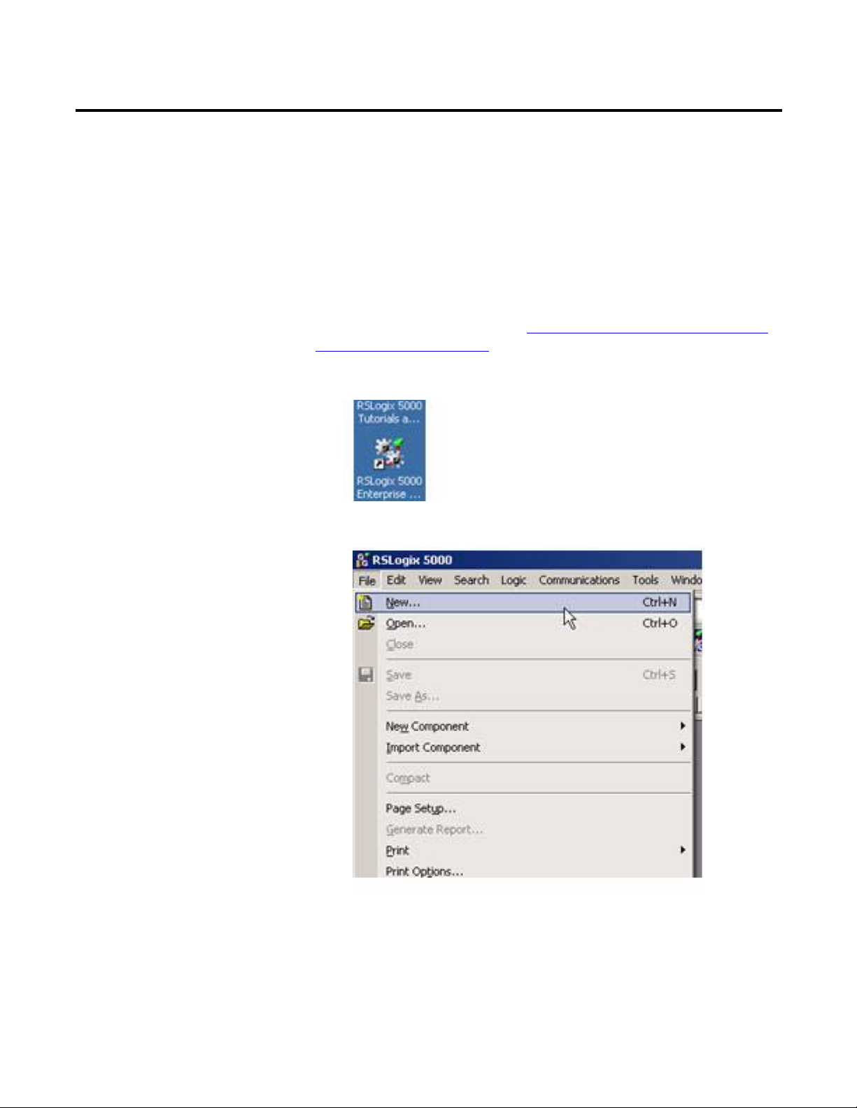
1. Open RSLogix 5000 by double-clicking on the icon on your desktop.
2. Select File>New to create a new project.
Rockwell Automation Publication 280E-PM001A-EN-P – August 2011 7
Chapter 1 ArmorStart® EtherNet/IP™ Communications & Control Programming Manual
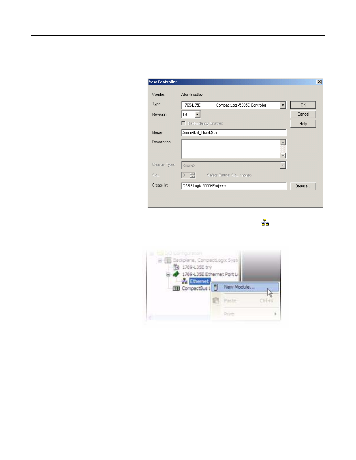
3. Enter the name of the project and select your controller from the Typ e
drop down menu. For this example, a Cat. No. 1769-L35E and software
revision 19 will be used. Then click OK.
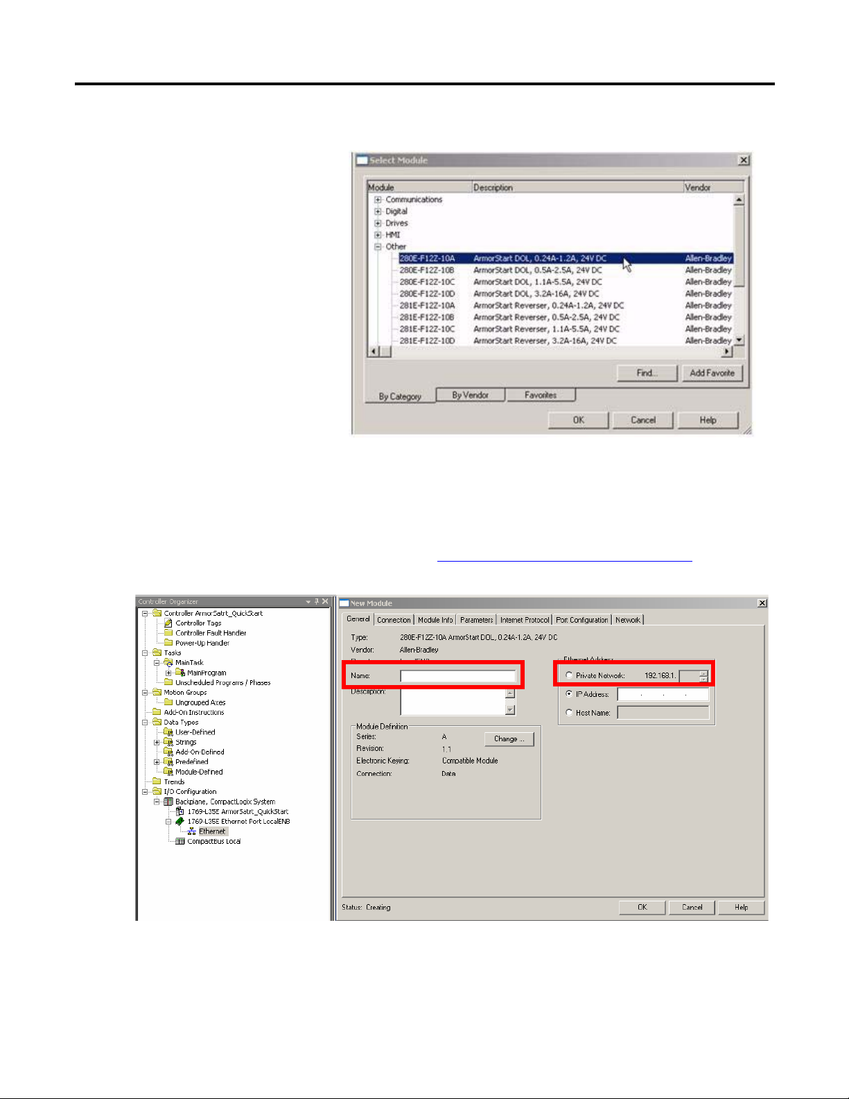
4. To add a new module to the tree, right-click on Ethernet and select
New Module. This allows you to add a new ArmorStart to the Logix
Project.
8 Rockwell Automation Publication 280E-PM001A-EN-P – August 2011
ArmorStart® EtherNet/IP™ Communications & Control Programming Manual Chapter 1
5. Select the ArmorStart in your application and click OK.
6. The AOP is shown below. Enter a Name for this ArmorStart and an
Ethernet address. For this example, the Private Network setting will be
used. This should be set to match the IP address switch setting on the
ArmorStart. Then press OK.
Note: Refer to Using the Rotary Network Address Switches
Appendix B to set an IP address on the device.
in
Rockwell Automation Publication 280E-PM001A-EN-P – August 2011 9

Chapter 1 ArmorStart® EtherNet/IP™ Communications & Control Programming Manual
Notes:
10 Rockwell Automation Publication 280E-PM001A-EN-P – August 2011
Chapter
2
Connect and Configure ArmorStart with Add-On-Profile (AOP)
This section will show the AOP tabs and how they can be used to connect, obtain
status, and configure the ArmorStart. Before the walkthrough is started, the
RSLogix 5000 software should be open and an AOP displayed as shown below.
The screenshot above displays that the AOP has seven tabs that can be used to
configure and/or monitor your ArmorStart. The following lists the tabs and
whether or not they are editable with the controller when OFFLINE, ONLINE,
or both:
• General – OFFLINE
• Connection – OFFLINE
• Module Info – ONLINE
• Parameters – OFFLINE/ONLINE
• Internet Protocol – ONLINE
Rockwell Automation Publication 280E-PM001A-EN-P – August 2011 11
Chapter 2 ArmorStart® EtherNet/IP™ Communications & Control Programming Manual
• Port Configuration – ONLINE
• Net work – ONLINE
The last five tabs in the list will not display information until the ONLINE
connection has been established with the ArmorStart. The General, Connection,
and Parameters tabs will be discussed first because they are used to define
OFFLINE settings so that connection with the ArmorStart can be established.
Offline Connection
General Tab
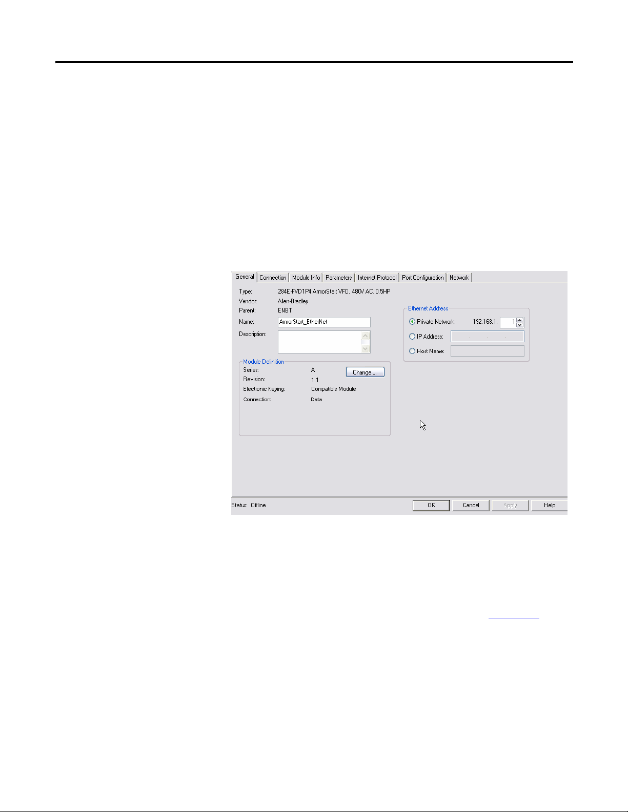
Click on the General tab to display the following:
This tab allows you to name your module, which should be descriptive and
representative of the module. The IP Address of the module must also be input
so that communication can be established. The IP Address should be the one
defined using the BootP/DHCP Server, the Rotary Network Address Switches
or the ArmorStart internal web server. For more information on how to set-up
the IP address of the ArmorStart using these methods, check Appendix B
For the majority of cases, the Host Name and Module Definition section of this
tab do not require any adjustment. Changes to either of these should only be
made if you are familiar with the functionality of each of these sections.
12 Rockwell Automation Publication 280E-PM001A-EN-P – August 2011
.
ArmorStart® EtherNet/IP™ Communications & Control Programming Manual Chapter 2
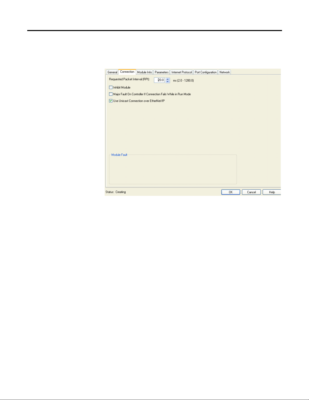
Connection Tab
Click on the Connection tab to display the following:
The Request Packet Interval (RPI) indicates the maximum frequency at which
data will be received. It is possible that data could come more quickly than the
time interval assigned in the RPI. In the majority of cases, the default 20 ms
should be the optimal setting. If you check the Inhibit Module option,
connection to controller tags will be broken. The Major Fault on Controller if
Connection Fails While in Run Mode option should be checked to ensure that
the controller processes the connection fault with the ArmorStart. The Use
Unicast Connection over EtherNet/IP is checked to use the Unicast mode
instead of the EtherNet/IP mode. This appears only for modules using
RSLogix 5000 software version 18 or later which supports Unicast.
Rockwell Automation Publication 280E-PM001A-EN-P – August 2011 13

Chapter 2 ArmorStart® EtherNet/IP™ Communications & Control Programming Manual
Parameters Tab
Click on the Parameters tab to display the following:
Online Connection
The parameters are divided into groups based on the type of ArmorStart. By
clicking in the Group drop down menu you can choose which parameter group is
displayed. When the Parameters tab is selected, the tab defaults to the Drive
Setup (Bulletin 284E) or Starter Setup (Bulletin 280E) groups depending on
the ArmorStart. These Setup groups are the minimum required parameters to get
the ArmorStart running.
After this parameter group has been set, the next time that the Parameters tab is
opened, all of the parameters will be shown and the tab will no longer default to
the setup groups.
Now that the offline connection settings have been set, connect to the
ArmorStart and review the last five AOP tabs.
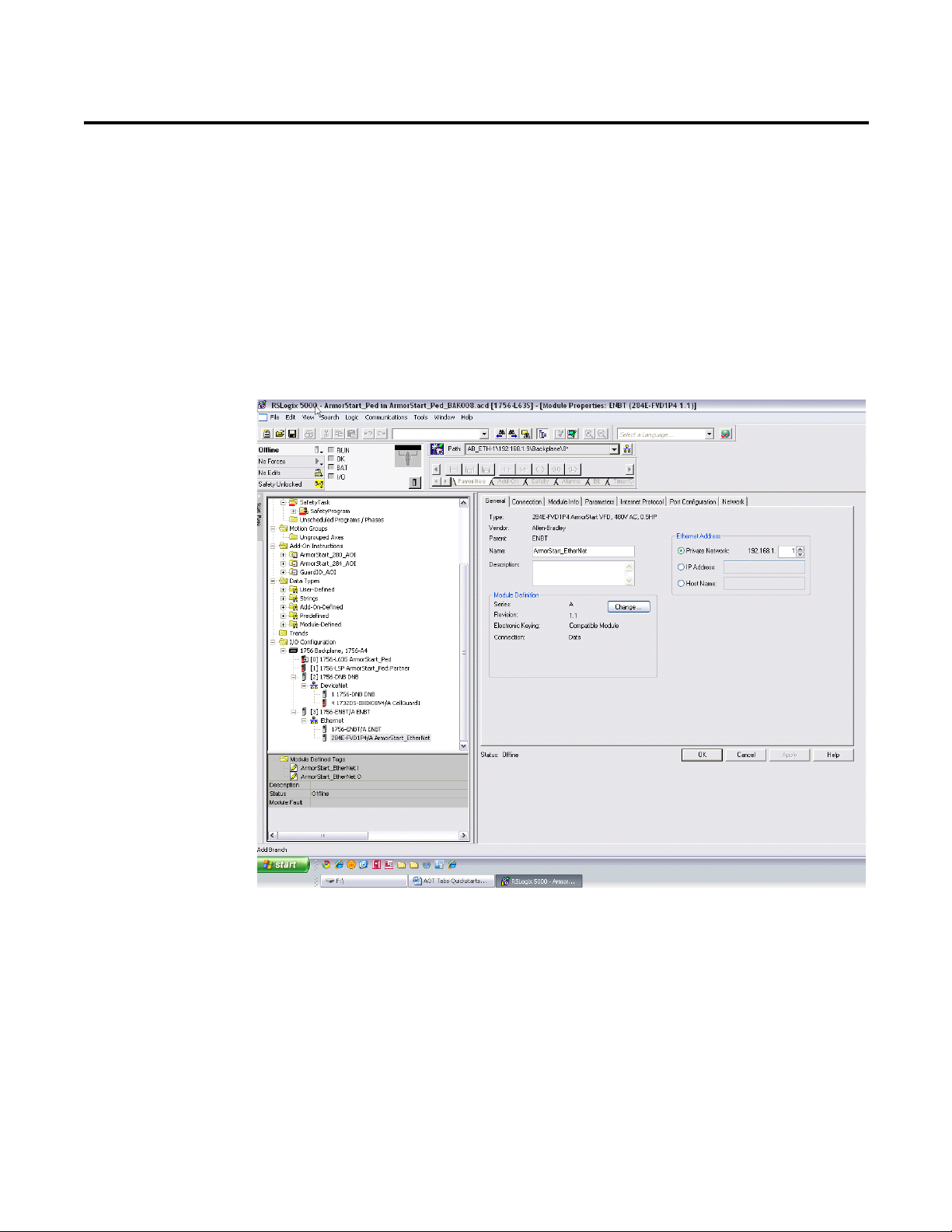
Note: If you are using a Cat. No. 1756-ENBT EtherNet module to communicate with
the PLC, verify that you have updated the module’s firmware to Revision 6.001 or
later. The latest firmware can be found at http://support.rockwellautomation.com/
controlflash/.
14 Rockwell Automation Publication 280E-PM001A-EN-P – August 2011

ArmorStart® EtherNet/IP™ Communications & Control Programming Manual Chapter 2
1. If a controller path is not set in the field shown below, you must first set a
path before going online with the controller. Click on the RSwho
button shown below.
2. Expand and browse the AB_ETHIP-1, Ethernet driver.
3. Select the Controller path. Then click Go Online.
Rockwell Automation Publication 280E-PM001A-EN-P – August 2011 15
Chapter 2 ArmorStart® EtherNet/IP™ Communications & Control Programming Manual
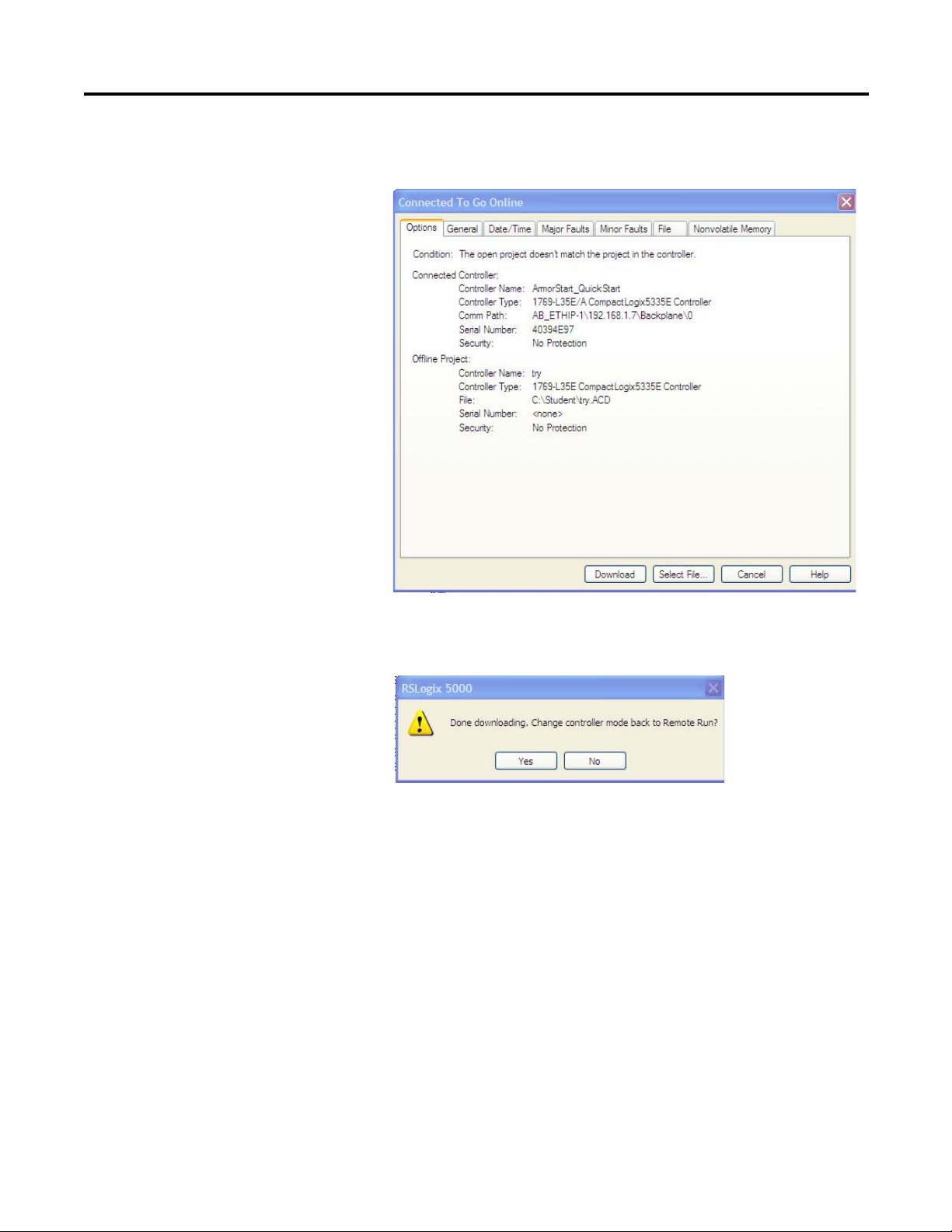
4. The following will appear and for this example, click on Download to
connect to the controller.
5. If a download confirmation dialog box appears, click Download again.
6. Click Ye s to bring the controller back to Remote Run.
16 Rockwell Automation Publication 280E-PM001A-EN-P – August 2011
ArmorStart® EtherNet/IP™ Communications & Control Programming Manual Chapter 2
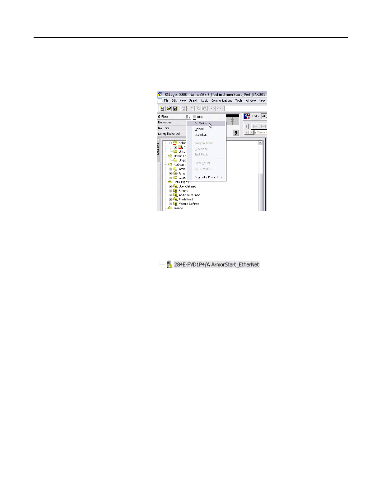
7. The controller should now be online. If at any point you go offline and a
path is selected, you can also go online by clicking the Offline drop down
in the upper left corner of the screen. Click on Go Online to connect to
the ArmorStart, as shown below.
Note: If a yellow triangle appears next to the ArmorStart Icon in the
Controller Organizer Tree as shown below, it means that the connection is
faulted. The problem must be fixed before you can connect to the
ArmorStart. The next steps assume that the connection was successful.
Rockwell Automation Publication 280E-PM001A-EN-P – August 2011 17
Chapter 2 ArmorStart® EtherNet/IP™ Communications & Control Programming Manual
Parameters Tab
Return to the Parameters tab again once the AOP is opened by selecting the
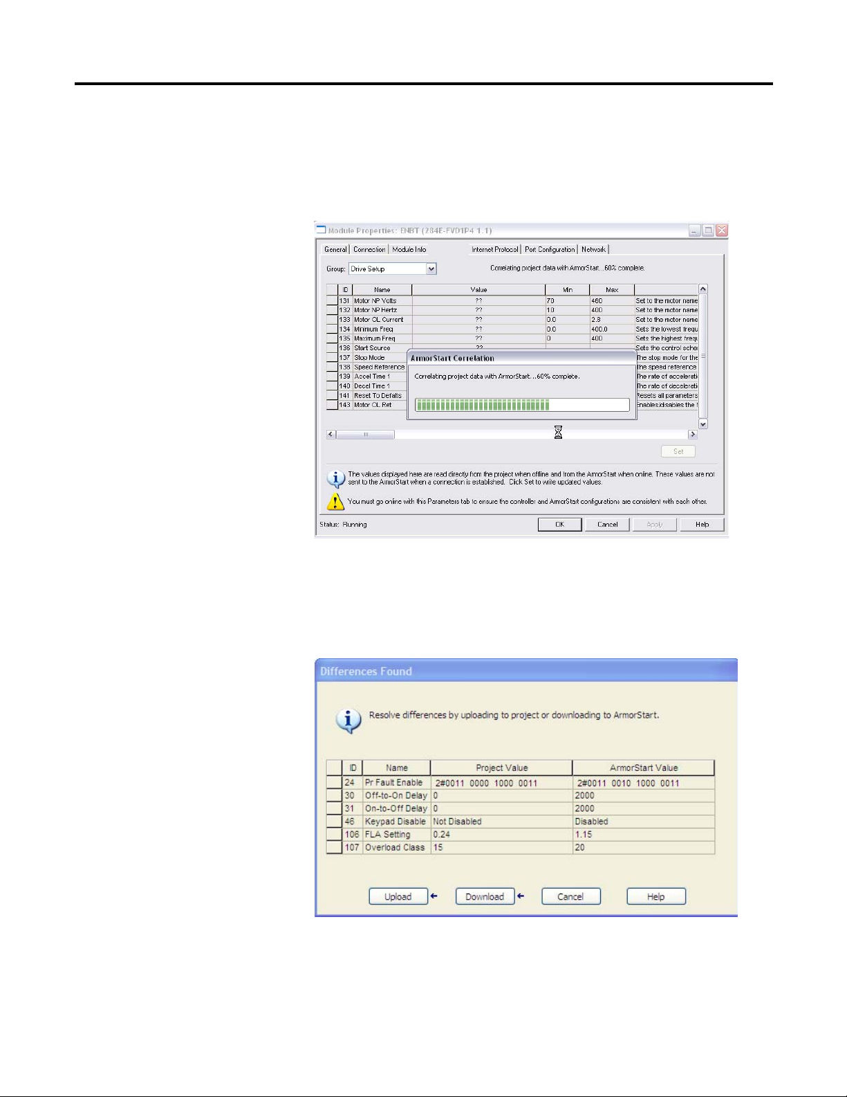
ArmorStart in the project tree. Notice that when clicking in the Parameters tab,
an ArmorStart Correlation pop-up window is displayed, as shown below.
This indicates that the AOP is comparing the parameter data entered offline vs.
the parameter data stored in the ArmorStart. If any discrepancies are found
between the parameters in the AOP and the parameters in the ArmorStart, a
window will pop-up, as shown below, asking you to decide which parameters you
want to keep.
If you want to keep the parameters in the AOP, select Download. If you want to
keep the parameters in the ArmorStart, select Uploa d. Otherwise, select Cancel.
Clicking Cancel will lock the user out of viewing the values. If you are connected
18 Rockwell Automation Publication 280E-PM001A-EN-P – August 2011
ArmorStart® EtherNet/IP™ Communications & Control Programming Manual Chapter 2
to a new ArmorStart and you just created the ArmorStart object and have not
made any changes in the parameters, the ArmorStart correlation should not find
any discrepancy.
Note: If you make any changes to the parameters offline, they will not be
downloaded to the ArmorStart when the connection is made (going Online). For
the Offline changes to take effect you must go to the Parameters tab. Once you
click the Parameters tab, ArmorStart correlation will take place and then the
changes can be downloaded to the ArmorStart.
Module Info Tab
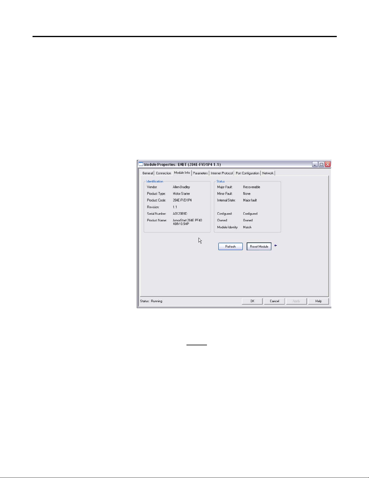
Click on the Module Info tab to display the following:
This tab will display general identification information, as well as status
information about the ArmorStart. It is important to note that the information
displayed in this tab will not
be constantly updated. After you click on the
Module Info tab, the AOP queries the ArmorStart once for the information
displayed in this tab and does not query the ArmorStart for the values again. If
after the initial query the status of the ArmorStart changes, for example a fault
occurs, the change in the status will not be automatically updated. The Refresh
button must be pressed to request the AOP for another ArmorStart query.
Note: A connection status (offline, online, downloading or uploading) is
provided at the bottom left of the tab window. The connection status appears in
all the tabs.
Rockwell Automation Publication 280E-PM001A-EN-P – August 2011 19
Chapter 2 ArmorStart® EtherNet/IP™ Communications & Control Programming Manual
Internet Protocol Tab
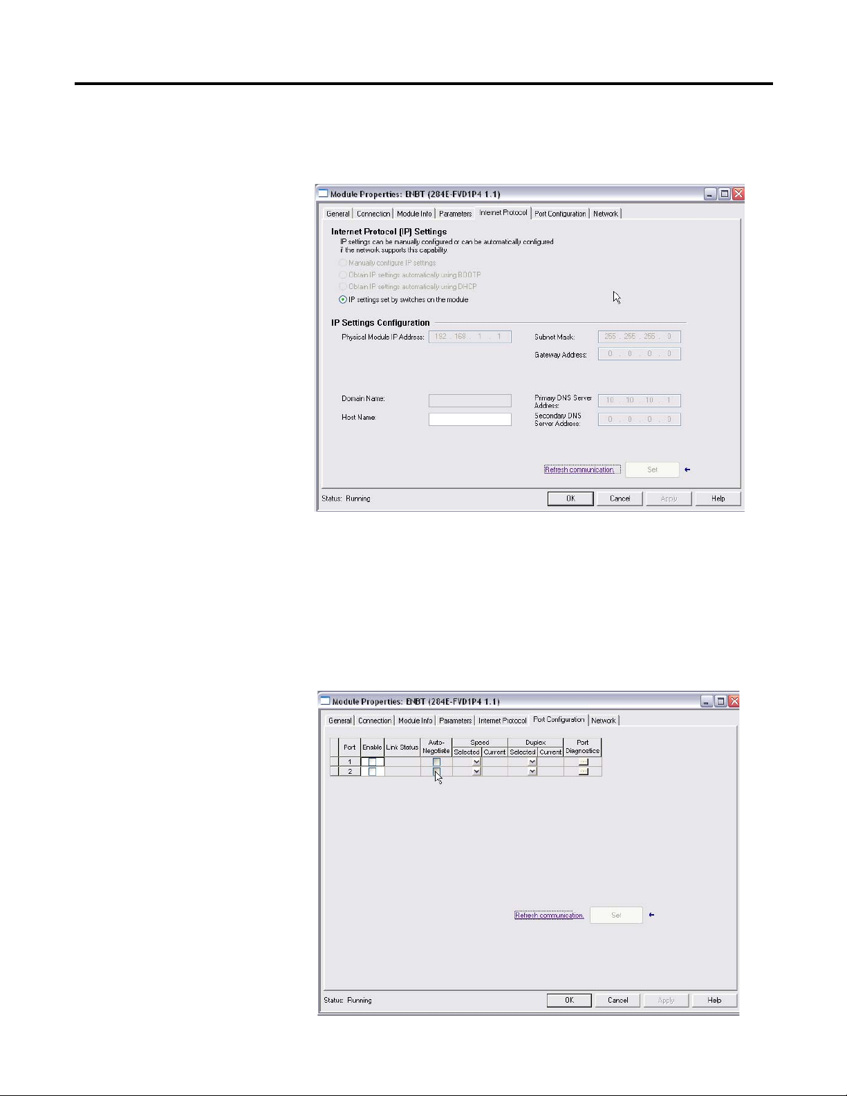
Click on the Internet Protocol tab to display the following :
If the IP address was set up using the Rotary Network Address Switches, default
settings for the IP would already be established and you will not be able to make
any changes in this tab. In most cases, you would not need to make any changes in
this tab and it will only display the current IP Settings Configuration.
Port Configuration Tab
Click on the Port Configuration tab to display the following:
20 Rockwell Automation Publication 280E-PM001A-EN-P – August 2011

ArmorStart® EtherNet/IP™ Communications & Control Programming Manual Chapter 2
This tab is used to enable or disable a physical port in the module. The ports will
normally be in Auto Negotiate mode, which in general, is the recommended
setting. Otherwise, you have to physically set the Speed or Duplex selection in
this tab. It is important to note that although there are two physical ports, they
act as one. Therefore, when you press either of the Port Diagnostic buttons,
information coming from both of the physical ports will be displayed.
Network Tab
Click on this tab to display the following:
This tab displays information about the network configuration, such as the type
of topology (linear or device level ring).
Rockwell Automation Publication 280E-PM001A-EN-P – August 2011 21

Chapter 2 ArmorStart® EtherNet/IP™ Communications & Control Programming Manual
Notes:
22 Rockwell Automation Publication 280E-PM001A-EN-P – August 2011
Chapter
3
ArmorStart Internal Web Server
Rockwell Automation provides an internal embedded web server with each
ArmorStart Ethernet/IP. The internal web server allows you to view information
and configure the ArmorStart via a web browser. You can also set up the
ArmorStart Ethernet/IP from the web server to send e-mail notifications. The
embedded web server is used to access configuration and status data. It provides
the user with the ability to view and modify the device configuration without
having access to RSLogix 5000. Security in the form of an administrative
password can be set. The default login is Administrator. There is no password
set by default. This programming manual will demonstrate how to access some
of the functions of the internal web server.
How to Access the ArmorStart Ethernet/IP Internal Web Server
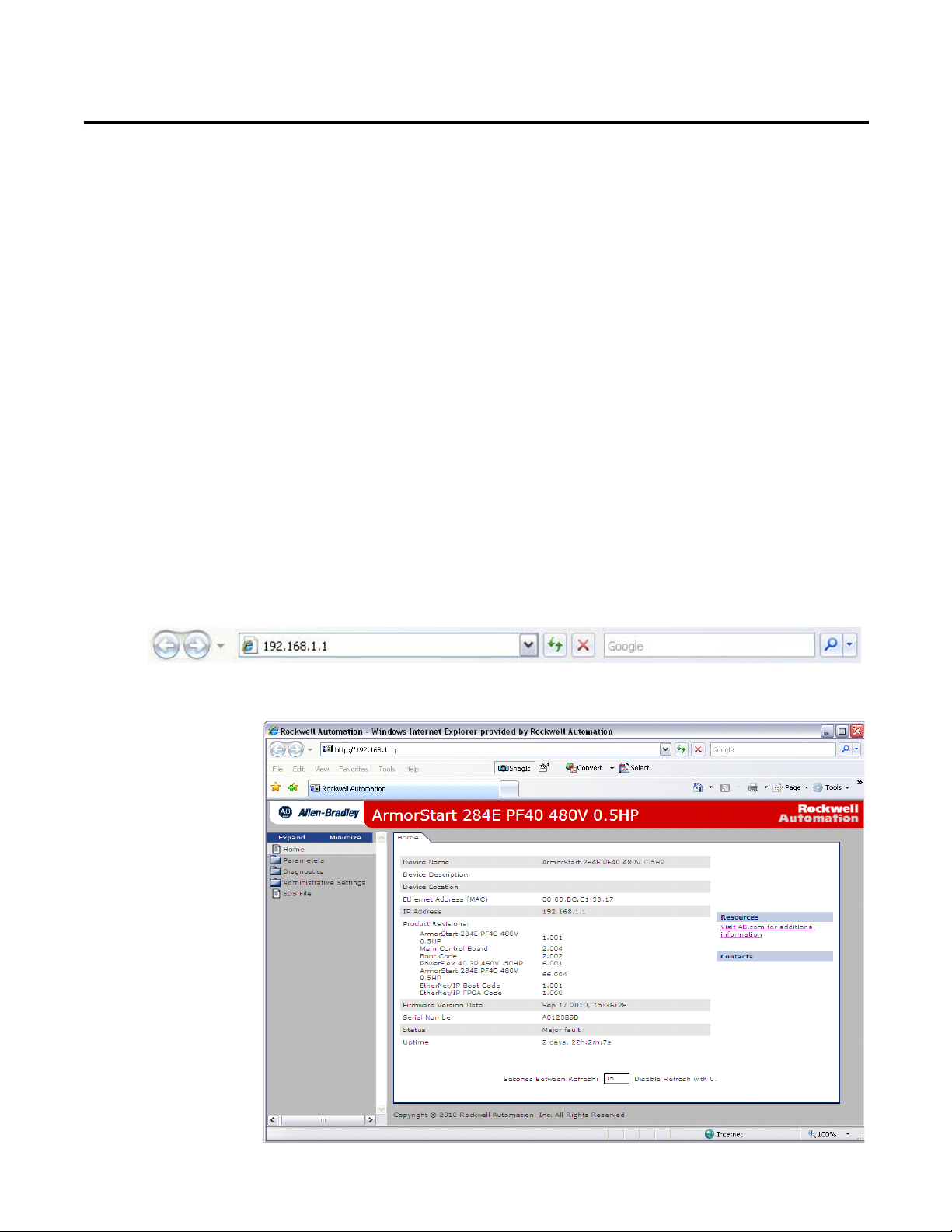
1. Open your preferred internet web browser.
2. Enter the IP address of the desired ArmorStart. For this example,
192.168.1.1 will be used. 192.168.1.1 is not the factory default IP
address.
3. The web server shown below should appear in your web browser.
Rockwell Automation Publication 280E-PM001A-EN-P – August 2011 23
Chapter 3 ArmorStart® EtherNet/IP™ Communications & Control Programming Manual
4. From here you are able to view parameter settings, the device status, and
diagnostics by clicking in any of the folders listed in the left side of the web
server.
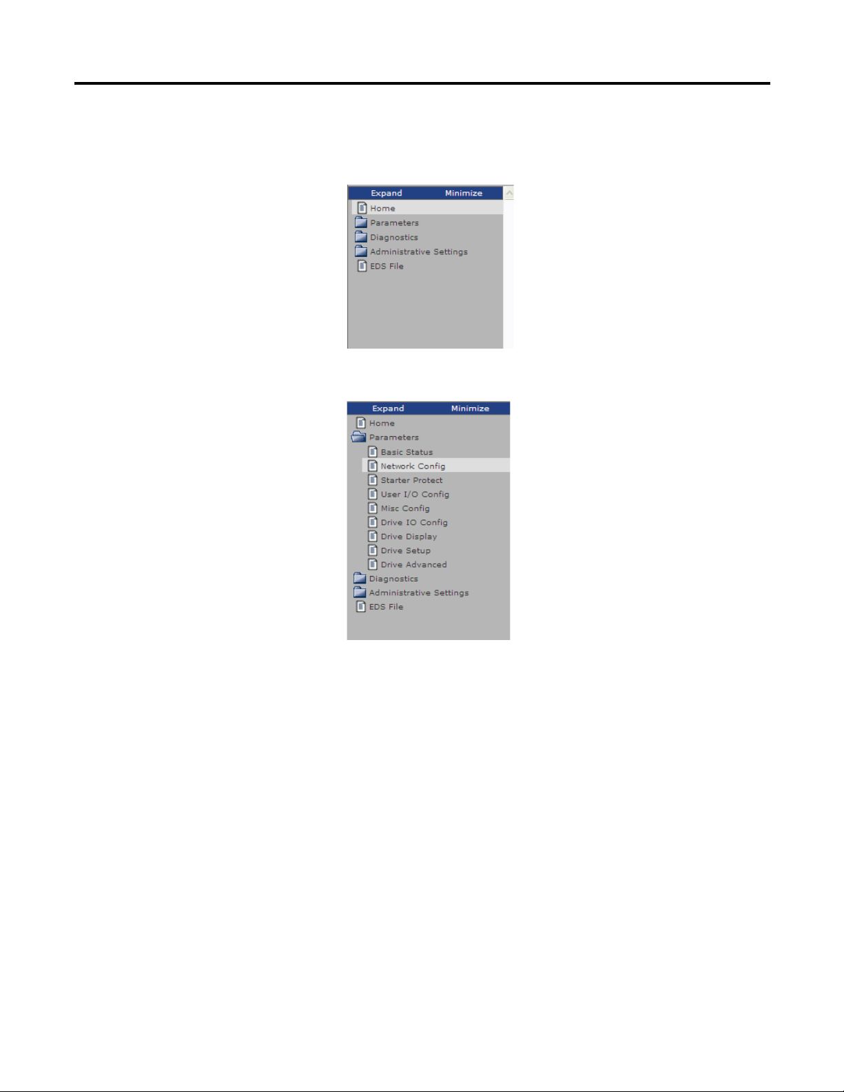
5. If you click in any of the folders they will expand and show their content.
24 Rockwell Automation Publication 280E-PM001A-EN-P – August 2011
ArmorStart® EtherNet/IP™ Communications & Control Programming Manual Chapter 3
6. If you click in any of the folder's contents, the web server will display the
content in multiple tabs.
Web Server Functionality
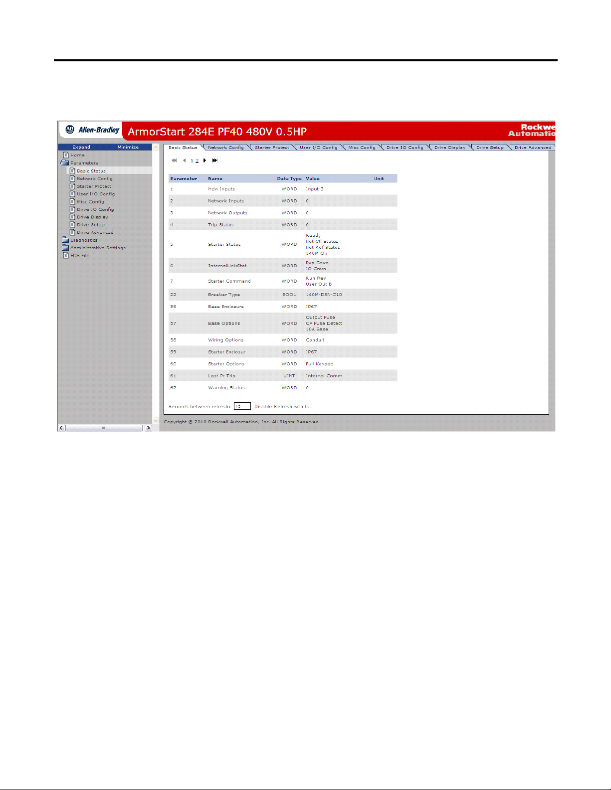
Navigate the folders using the tabs or the sub-groups categories in the
folders. In the screen shown above, you can find the ArmorStart's
Basic Status tab where information such as the FLA setting, last fault
experienced, and more, can be obtained.
Note: Set refresh rate on the bottom of the screen shown above to
2 seconds to be able to observe basic status while using the browser.
Once the web server has been accessed from the web browser, you can click in any
of the folders in the left side of the web server to look for the desired information
or to configure the desired parameter. Next, the functionality of the web server
will be discussed, starting with the Parameters folder.
Rockwell Automation Publication 280E-PM001A-EN-P – August 2011 25

Chapter 3 ArmorStart® EtherNet/IP™ Communications & Control Programming Manual
Parameters
1. Click on the Parameters folder. This will expand the folder. The
parameters are divided into different categories, as shown in the figure
below.
2. Parameters can be viewed and modified using the web browser. For
example, to edit Setup parameter(s), start by clicking either Starter Setup
or Drive Setup group to display the following screen.
26 Rockwell Automation Publication 280E-PM001A-EN-P – August 2011
ArmorStart® EtherNet/IP™ Communications & Control Programming Manual Chapter 3
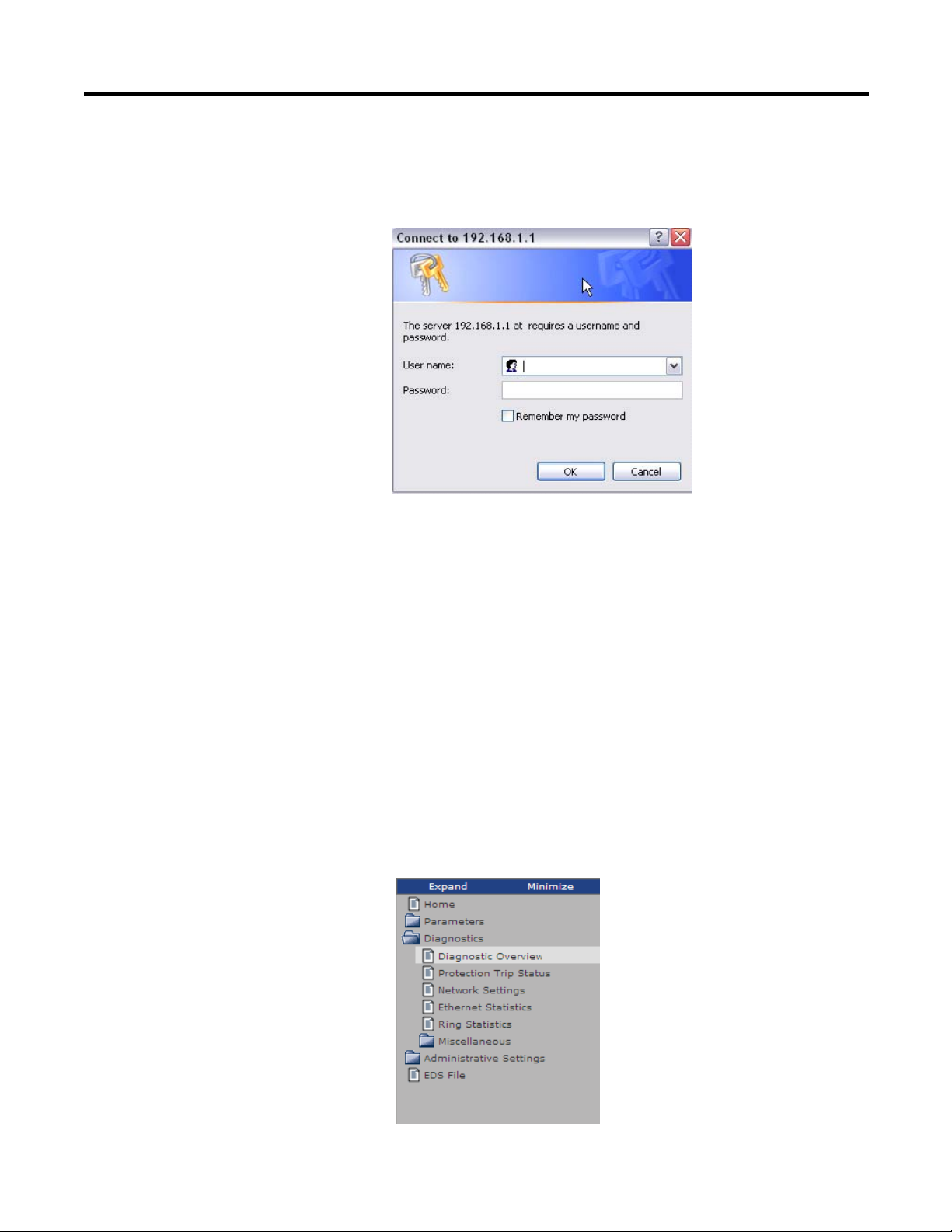
3. To modify a parameter click the Edit button. This will bring up the
following pop-up window, which prompts the user to enter the User Name
and Password. The default User Name is Administrator and there is no
password set by default.
Note: The user is expected to change the User Name (Log in) and
Password to avoid unauthorized access to the device configuration. This
process is described later in this publication.
4. Once the correct User Name and Password have been entered, the
parameters can be edited.
Note: It is recommended to use the RSLogix 5000 AOP to make
parameter changes. This ensures changes will be recorded in the project
file. The Web Server should only be used to change parameters if it is the
only available option.
Diagnostics
1. The Diagnostics folder contains information regarding the ArmorStart.
The information is grouped in different categories, as shown in the figure
below. This information can be used to troubleshoot or take preventative
action before a problem arises in the specific application that is running.
Rockwell Automation Publication 280E-PM001A-EN-P – August 2011 27
 Loading...